Embed Size (px)
Citation preview

801—1
SECTION 801 CEMENT
801.01 REQUIREMENTS. Provide portland cement from approved mills listed in theDepartment’s List of Approved Materials. Mills obtain approval by furnishing theDepartment samples and certified mill test data developed over the previous 6 months.Approved cement mill laboratories are AASHTO accredited in ASTM C150 test methods.Foreign cements are added to the approved list based upon testing by the sponsoringapproved cement mill laboratory along with submittal and approval of verificationsamples.
The Department will require a signed certification from the supplier for each shipmentof cement stating that the cement complies with the applicable ASTM standard and alladditional requirements of this subsection.
Conform to the following requirements for cement:
1) Type I, II, III, and IV conforms to ASTM C 150. State, on the mill certification, thenature, amount, and identity of any processing addition and its compliance withASTM C 465.
2) Type K conforms to ASTM C 845.3) Type IP or Type IPA conforms to ASTM C 595, and the following additional
requirements to Type IP and IPA:
a) The pozzolan constituent shall be fly ash. Ensure that the loss on ignition of thefly ash does not exceed 3.0 percent.
b) Ensure that the fly ash does not exceed 20 percent of the portland-pozzolancement, by weight. The cement manufacturer shall furnish a statement to theEngineer stating the actual fly ash content in each shipment.
c) The cement manufacturer shall furnish to the Engineer reports showing theresults of tests performed on the fly ash used in the manufacture of the Type IPcement shipped to the project. The tests shall cover the chemical and physicalproperties listed in ASTM C 618.
d) The cement manufacturer shall have a qualified technical representative readilyavailable for consultations on the project at any time the Engineer deemsnecessary, at no expense to the Department.
e) Use only one brand of Type IP cement throughout the project, unless theEngineer approves a change in brand in writing.
4) Types IS or I(SM) conforms to ASTM C 595 and the following additional requirements:
a) Use Grade 100 or 120 ground granulated blast furnace slag (GGBF slag)conforming to the requirements of ASTM C 989.
b) Ensure that the GGBF slag does not exceed 30 percent, by weight, of the portlandblast furnace slag for Type IS.
c) The cement manufacturer shall furnish to the engineer reports showing the resultsof the tests performed on the GGBF slag used in the manufacturing of the TypeIS and I(SM) shipped to the project. The tests shall cover the chemical andphysical properties required in ASTM C 989.
d) The cement manufacturer shall have a qualified technical representative readilyavailable for consultation on the project at anytime the Engineer deemsnecessary, at no expense to the Department.
e) Use only one brand of Type IS or I(SM) cement throughout the project, unless theEngineer approves otherwise.
Even when tested and approved, do not mix cement from different mills in individualbatches or use cement from different mills in alternate batches of concrete. Subject to theabove restrictions, the Engineer may allow the use of cements from different mills for any
801—2
structure or individual elements of a structure, provided color contrasts resulting from theirusage is minimal or is otherwise unobjectionable and identification of the location ofconcrete containing the different cements is satisfactorily maintained.
Store cement to prevent damage from the elements. Provide weatherproof storagefacilities with sufficient storage capacity that cements from different mills or of differenttypes will not become intermixed.
Provide an acceptable means for obtaining samples, from either the cement silo,weigh hopper, or truck.
The Engineer will reject cement that for any reason has become damaged throughcontamination, partial set, or which contains lumps of caked cement. The Engineer mayreject the entire contents of a container when it contains damaged cement.
The Engineer may accept cement producing an air content of mortar between 12 and16 percent when it is to be used in air-entraining concrete and the air content of theconcrete is controlled at the mixer.
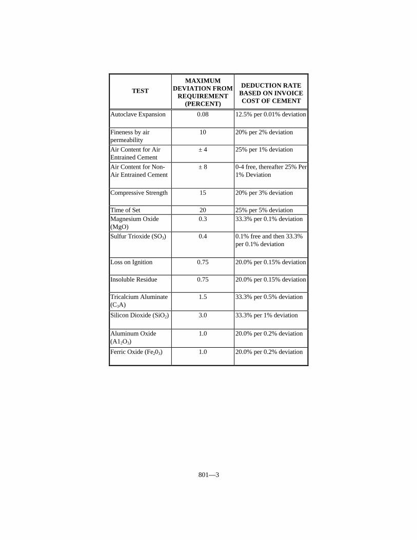
801.02 NON-SPECIFICATION CEMENT. The Department accepts cement on thebasis of manufacturer’s certification attesting to type and conformance to the applicableASTM specification. The Engineer will take check samples. When the check samples donot conform to these specifications, the Department will make deductions as shown in thefollowing table. When a sample fails more than one test, the Department will make thetotal deduction as the sum of deductions up to a maximum of 100 percent.
801—3
TEST
MAXIMUMDEVIATION FROM
REQUIREMENT(PERCENT)
DEDUCTION RATEBASED ON INVOICECOST OF CEMENT
Autoclave Expansion 0.08 12.5% per 0.01% deviation
Fineness by airpermeability
10 20% per 2% deviation
Air Content for AirEntrained Cement
± 4 25% per 1% deviation
Air Content for Non-Air Entrained Cement
± 8 0-4 free, thereafter 25% Per1% Deviation
Compressive Strength 15 20% per 3% deviation
Time of Set 20 25% per 5% deviationMagnesium Oxide(MgO)
0.3 33.3% per 0.1% deviation
Sulfur Trioxide (SO3) 0.4 0.1% free and then 33.3%per 0.1% deviation
Loss on Ignition 0.75 20.0% per 0.15% deviation
Insoluble Residue 0.75 20.0% per 0.15% deviation
Tricalcium Aluminate(C3A)
1.5 33.3% per 0.5% deviation
Silicon Dioxide (SiO2) 3.0 33.3% per 1% deviation
Aluminum Oxide(A12O3)
1.0 20.0% per 0.2% deviation
Ferric Oxide (Fe203) 1.0 20.0% per 0.2% deviation

802—1
SECTION 802 ADMIXTURES FOR CONCRETE
802.01 REQUIREMENTS. Provide admixtures conforming to the followingrequirements:
802.01.01 Air-Entraining. AASHTO M 154, except the chloride content (as Cl)shall not exceed one percent by weight. The Department may require tests for bleeding,time of setting, and length change.
802.01.02 Water-Reducing and Retarding. AASHTO M 194, Type D, except therelative durability factor shall not be less than 90 and the chloride content (as Cl) shall notexceed one percent by weight.
802.01.03 Water-Reducing. AASHTO M 194, Type A, except the relativedurability factor shall not be less than 90 and the chloride content (as Cl) shall not exceedone percent by weight.
802.01.04 Water-Reducing and Accelerating. AASHTO M 194, Type E, exceptthe relative durability factor shall not be less than 90 and the chloride content (as Cl) shallnot exceed one percent by weight. Use water reducing and accelerating admixture onlywhen the Engineer has reviewed proposed procedures for mixing, handling, and placingthe concrete, and has given written permission to proceed.
802.01.05 Water-Reducing, High Range. AASHTO M 194, Type F, except therelative durability factor shall not be less than 90 and the chloride content (as Cl) shall notexceed one percent by weight.
802.01.06 Water-Reducing, High Range and Retarding. AASHTO M 194, TypeG, except the relative durability factor shall not be less than 90 and the chloride content (asCl) shall not exceed one percent by weight.
802.01.07 Accelerating. AASHTO M 194, Type C, except the relative durabilityfactor shall not be less than 90 and the chloride content (as C1) shall not exceed onepercent by weight.
802.02 APPROVAL. Select admixtures from the Department’s List of ApprovedMaterials. The Department places admixtures on the list based on evidence of compliancewith requirements when determined by either tests performed by the Department; certifiedtest data furnished by a recognized laboratory providing such laboratory shall be oneregularly inspected by the Cement and Concrete Reference Laboratory of ASTM; for air-entraining admixtures that are aqueous solutions of Vinsol Resin, manufacturer’s shallsubmit a certification in the following form:
This is to certify that the product (trade name) as manufacturedand sold by (company) is an aqueous solution of Vinsol Resin that hasbeen neutralized with sodium hydroxide. The ratio of sodiumhydroxide to Vinsol Resin is one part of sodium hydroxide to (number)parts of Vinsol Resin. The percentage of solids based on the residuedried at 105 ΕC is (number). No other additive or chemical agent ispresent in this solution.
The Engineer will not require testing of admixtures included on the Department’s Listof Approved Materials at the time of their use unless there is indication in actual field useof harmful effects on the properties of the concrete or when the Engineer considers testingnecessary for other reasons.
The Department will continue to include an admixture on the list contingent upon
802—2
satisfactory performance in actual project use and an annual certification containing thefollowing information:
1) A statement that the admixture to be furnished during the particular calendar year isof the same composition as that previously approved for inclusion on the approvedlist.
2) A statement that the admixture conforms to the appropriate requirements of AASHTOM 194 or AASHTO M 154, as applicable.
3) A statement that the chloride content (as Cl) does not exceed one percent by weight.4) A statement that notification will be made to the Division of Materials of any changes
in composition before furnishing the material to projects.
The Department provides the specific details governing verification and documentingapproved status of admixtures at the time of use in the Department’s Manual of FieldSampling and Testing Practices.
803—1
SECTION 803 WATER
803.01 GENERAL. Use water for mixing or curing concrete, emulsified asphalt, orother similar materials that is reasonably clean and free from oil, salt, acid, alkali, sugar,vegetable, or other substances injurious to the finished product. The Engineer may test thewater at any time for its suitability for a particular use.
The Engineer will ordinarily accept water supplied by public distribution systemswithout testing.
The Engineer will require testing of mixing water for use in concrete when not from apublic distribution system.
Provide water that when tested by KM 64-226 does not contain impurities in excess ofthe following limits:
Acidity or Alkalinity Calculated 0.05 Percentin terms of Calcium Carbonate
Total Organic Solids 0.10 PercentTotal Inorganic Solids 0.10 PercentChloride Content (as Cl) 1,000 parts per million
804—1
SECTION 804 FINE AGGREGATES
804.01 GENERAL. Fine aggregates include, but at the discretion of the Engineer arenot limited to, natural sand, crushed sand, conglomerate sand, mortar sand, mineral filler,and lightweight aggregates where permitted.
The Department’s List of Approved Materials includes the Aggregate Source List andthe list of Class A and Class B Polish-Resistant Aggregate Sources.
804.01.01 Natural Sand. Provide fine granular material resulting from the naturaldisintegration of rock.
804.01.02 Crushed Sand. Provide fine granular material resulting from crushing ofstone or gravel. Includes slag where permitted.
804.01.03 Conglomerate Sand. Provide natural materials primarily processed to thedesired sizes, without crushing. Conglomerate sand may include some crushed naturalmaterial.
804.01.04 Mortar Sand. Provide natural, crushed, or conglomerate sand suitable foruse in cement mortar.
804.01.05 Mineral Filler. Provide limestone dust, cement, fly ash, or other inertmineral matter.
804.02 APPROVAL. Provide fine aggregates from sources included on the AggregateSource List meeting the description and requirements specified in this section.
The Department will consider a source for inclusion on the Aggregate Source Listwhen the aggregate producer provides the following:
1) A Quality Control Plan.2) A satisfactory laboratory facility with all necessary testing equipment.3) A Qualified Aggregate Technician to perform the required testing.
When a supplier wishes to supply sand only for asphalt mixtures, Items 1, 2 and 3above will be waived. The Department may add the source to the Aggregate Source Listand restrict its use to asphalt mixtures.
Obtain the Department’s approval before furnishing aggregate from sources not onthe Aggregate Source List. The Department will sample the aggregate during stockpilingand test according to the Department’s Manual of Field Testing and Sampling Practices.
The Department will reject aggregate when excessive variation of gradation orphysical properties cause unworkable mixtures, mixture control problems, or non-conformance to the finished product or mixture requirements.
The Department will reject contaminated aggregate when the Engineer deems it couldbe detrimental to the finished product.
804.03 CONCRETE. Provide natural, crushed, or conglomerate sand. Use natural orconglomerate sands as fine aggregates in concrete intended as a wearing surface for traffic. The Department will allow any combination of natural, crushed, or conglomerate sandwhen the combination is achieved in the concrete plant weigh hopper. The Engineer mayallow other sands.
Conform to the following:
1) Sand Equivalent - 80 (minimum).2) Soundness - 10% loss (maximum).3) Friable Particles - 3.0% (maximum).4) Coal plus Lignite - 0.5% (maximum).
804—2
5) Uncompacted Voids(1) – 47.0% (maximum).6) Organic Impurities - Not darker than the standard.7) Mortar Strength(2) - 95% at 7 calendar days (minimum).8) Gradation(1):
Sieve Size Percent Passing3/8 inch 100
No. 4 90-100No. 16 45-85No. 50 5-25No. 100 0-8
(1) The Department will permit fine aggregates exceeding when they are used ina combination that meets requirements.
(2) The Department will require testing for mortar strength only for sand notpassing the test for organic impurities and will supersede the requirementfor organic impurities.
The Department will waive the requirements for gradation, sand equivalent, anduncompacted voids for concrete pipe.
804.04 ASPHALT MIXTURES. Provide natural, crushed, conglomerate, and slagsand, with the addition of filler as necessary, to meet gradation requirements. TheDepartment will allow any combination of natural, crushed, conglomerate, and slag sandwhen the combination is achieved using cold feeds at the plant.
804.04.01 Sand for Mixtures.
1) Gradation - 100 percent passing the 3/8 inch sieve with more than 50 percent passing the No. 4 sieve.
2) Coal Plus Lignite - 5.0 percent maximum.3) Soundness - 15 percent maximum.
804.04.02 Mineral Filler. Ensure 100 percent passes the No. 16 sieve and at least30 percent passes the No. 200 sieve.
804.04.03 Polish-Resistant Aggregate. Provide fine aggregates required for polish-resistant applications from a Class A or B Polish-Resistant Aggregate Source as required. In addition to these listed sources, the Department will consider natural sand,conglomerate sand, and crushed gravel sand meeting the requirements of Section 804 to beClass A polish-resistant.
804.04.04 Requirements for Combined Aggregates.
A) Uncompacted Voids. Provide aggregates for Superpave mixtures meeting theminimum voids content as listed in the Superpave Fine Aggregate ConsensusProperty Requirements table.
B) Sand Equivalent. Provide aggregate having a sand equivalent value of 45 orgreater for the portion of the total combined aggregates passing the No. 4 sieve.Provide aggregates for Superpave mixtures meeting the minimum sandequivalent limits as listed in the Superpave Fine Aggregate Consensus PropertyRequirements table.
The sand equivalent limits specified in this section apply to aggregates inthe final mixture. The Department will normally take samples from stockpiledaggregates or aggregate cold feeds, including mineral filler, for acceptancetesting. When these tests do not meet the required values, make trial runs throughthe plant to provide material for sampling which is intended for the final mixture.
The Department may waive the sand equivalent requirement provided the

804—3
portion of the combined aggregate passing the No. 40 sieve is non-plasticaccording to AASHTO T 90.
SUPERPAVE FINE AGGREGATE CONSENSUS PROPERTYREQUIREMENTS
Uncompacted Void Contentof Fine Aggregate (Percent),(1) Sand Equivalent
ESAL Design ESALs Minimum (Percent),Class (millions) (Depth From Surface) Minimum
≤ 100 mm > 100 mm1 < 0.3 40.0 40.0 452 0.3 to < 3 40.0 40.0 453 3 to < 30 45.0 40.0 454 ≥ 30 45.0 45.0 50
(1) Performed according to AASHTO T 304, Method A.
C) Friable Particles. Limit friable particles, excluding sandstone, to a maximum of1.0 percent of the total combined aggregates.
D) Absorption. Provide aggregates having a water absorption of no more than 3.0percent for each aggregate type. When slag is used, provide total combinedaggregates having a water absorption of no more than 4.0 percent.
804.05 MORTAR SAND. Provide natural sand, crushed sand, or conglomerate sandconforming to Subsection 804.03 with the exception of Uncompacted Voids andGradation. Conform to the following gradation:
Sieve Size Percent PassingNo. 8 100No. 50 10-40No. 100 0-10
804.06 EPOXY SEAL COATS. Provide either natural or conglomerate sand having aninsoluble content of 90 percent or greater. Conform to the following gradation:
Sieve Size Percent PassingNo. 16 100No. 50 10-40No. 100 0-5
804.07 EPOXY SAND SLURRY. Provide silica sand containing no less than 90percent insolubles. Ensure the sand is rounded to subangular, clean, dry and non-friable. Conform to the following gradation:
Sieve Size Percent PassingNo. 8 100No. 50 0-40
No. 100 0-5
The Department may allow material not meeting this gradation if it produces aworkable mixture and an acceptable slurry seal.
804.08 PIPE BEDDING. Provide natural, crushed, or conglomerate sand having asand equivalent of 20 or greater. The Department may waive the sand equivalent

804—4
requirement when the portion passing the No. 40 sieve is non-plastic according toAASHTO T 90. Conform to the following gradation:
Sieve Size Percent Passing3/8 inch 100No. 100 0-15
804.09 UNDERDRAINS, EMBANKMENT DRAINAGE BLANKET, ANDNATURAL SAND FOR DRAINAGE AND BACKFILL. Provide natural sand havinga sand equivalent of 70 or greater. Conform to the following gradation:
Sieve Size Percent Passing3/8 inch 100
No. 4 75-100No. 100 0-8
804.10 GRADATION ACCEPTANCE OF NON-SPECIFICATION FINEAGGREGATE. When reasonably acceptable work has been produced using theaggregate in question, the Department may accept the work according to Subsection105.04. When the Engineer determines that the aggregate not conforming to gradationrequirements may be left in place, the Department will accept the aggregate at a reductionin the Contract unit bid price for the work containing the aggregate according to thefollowing procedures. The Department will not consider these procedures a means tocontinue accepting non-specification aggregates.
The Department will base the reduction on the invoice price for the aggregate at thesource. When satisfactory invoices are not furnished, the Department will use current binprices for that source on file with the Cabinet’s Division of Purchases. The maximumdeduction for non-specification material, which is allowed to remain in place, is 50percent.
When aggregate fails to conform to gradation on more than one sieve, the Departmentwill apply the largest payment reduction.
The Department will define a lot based on the smallest definable quantity of materialrepresented by acceptance test results, either passing results or failing results, or both. Normally, the Department will average all test results for the lot to determine the test resultfor payment according to the deduction tables. However, when test results are notreasonably uniform the Department will not average the high and low test results within alot. The Department will assign each test result to equal quantities in new smaller lots inproportion to the number of tests representing the original lot. When daily tests areperformed, the lot will be a day’s production unless the Department defines a smaller lot.
When 2 consecutive lots contain non-specification material, discontinue the use of theaggregate until the Department makes a decision concerning the overall acceptability ofthe aggregate from that source.
The Department will not impose a reduction in payment for quantities less than 50tons unless the Engineer deems it necessary.

804—5
GRADATION - CONCRETE SAND
Payment Sieve Size-Percent PassingReduction 3/8 inch No. 4 No. 16 No. 50 No. 100
0% 100 90-100 45-85 5-25 0-810% 43-44 3-410% 98-99 88-89 86-87 26-27 920% 42 220% 97 87 88 28 1030% 41 130% 96 86 89 29 1150% 40 050% 95 85 90 30 12
GRADATION - MINERAL FILLER
Payment Sieve Size-Percent PassingReduction No. 16 No. 200
0% 100 30 minimum10% 98-99 2920% 97 2830% 96 2750% 95 26
GRADATION - MORTAR SAND
Payment Sieve Size-Percent PassingReduction No. 8 No. 50 No. 100
0% 100 10-40 0-1010% 8-910% 98-99 41-42 1120% 720% 97 43 1230% 630% 96 44 1350% 550% 95 45 14

804—6
804.11 SAMPLING AND TESTING. The Department will sample and test accordingto the following methods when applicable:
Absorption (Fine Aggregate) AASHTO T 84Coal and Lignite KM 64-615Dry Sieve Analysis AASHTO T 27Friable Particles AASHTO T 112Insoluble Content (Fine Aggregate) KM 64-224Mortar Strength AASHTO T 71Organic Impurities AASHTO T 21Plastic Limit and Plasticity Index AASHTO T 90Sampling AASHTO T 2Sand Equivalent AASHTO T 176Sieve Analysis of Mineral Filler AASHTO T 37Soundness KM 64-610Uncompacted Voids (Method A) AASHTO T 304Wet Sieve Analysis KM 64-620 or AASHTO T 27
GRADATION - SAND FOR EPOXY SEAL COAT
Payment Sieve Size-Percent PassingReduction No. 16 No. 50 No. 100
0% 100 10-40 0-510% 8-910% 98-99 41-42 620% 720% 97 43 730% 630% 96 44 850% 550% 95 45 9
GRADATION - PIPE BEDDING
Payment Sieve Size-Percent PassingReduction 3/8 inch No. 100
0% 100 0-1510% 98-99 1620% 97 1730% 96 1850% 95 19
GRADATION - UNDERDRAINS, EMBANKMENT DRAINAGE BLANKET,AND NATURAL SAND FOR DRAINAGE AND BACKFILL
Payment Sieve Size-Percent PassingReduction 3/8 inch No. 4 No. 100
0% 100 75-100 0-810% 98-99 73-74 920% 97 72 1030% 96 71 1150% 95 70 12

805—1
SECTION 805 COARSE AGGREGATES
805.01 GENERAL. Coarse aggregates include, but at the discretion of the Engineer arenot limited to, crushed stone and crushed or uncrushed gravel. Includes lightweightaggregates or slag where permitted.
The Department’s List of Approved Materials includes the Aggregate Source List andthe list of Class A and Class B Polish-Resistant Aggregate Sources.
805.02 APPROVAL. Provide coarse aggregates from sources included on theAggregate Source List meeting the description and requirements specified in this section.
The Department will consider a source for inclusion on the Aggregate Source Listwhen the aggregate producer provides the following:
1) A Quality Control Plan.2) A satisfactory laboratory facility with all necessary testing equipment.3) A Qualified Aggregate Technician to perform the required testing.
Obtain the Department’s approval before furnishing aggregate from sources not onthe Aggregate Source List. The Department will sample the aggregate during stockpilingand test according to the Department’s Manual of Field Testing and Sampling Practices.
The Department will reject aggregate when excessive variation of gradation orphysical properties cause unworkable mixtures, mixture control problems, or non-conformance to the finished product or mixture requirements.
Coarse aggregates are subject to preliminary source approval.
805.03 GENERAL REQUIREMENTS. Provide coarse aggregates that are free ofobjectionable amounts of clay lumps, dirt coatings, and foreign material. The Departmentwill reject contaminated aggregate when the Engineer deems it could be detrimental to thefinished product.
805.03.01 Soundness and Shale. Conform to the following:
SHALE SOUNDNESS AGGREGATE USE PERMITTED(1) REQUIREMENT
(Maximum %) (Maximum %)
Portland Cement Concrete MixturesAggregate for Bridge Decks, Bridge Deck Overlays,and Bridge Barrier Walls 1.0 9All Other Concrete Classes and Uses 2.0 12
Asphalt MixturesAggregate for Polish Resistant Surfaces and AsphaltSurface Under OGFC:
Limestone and Dolomite 1.0 9Other Aggregate Types 2.0 12
All Other Asphalt Mixtures 2.0 15
Other UsesSizes No. 610 or 710 When Used for Aggregate
Surfacing, Traffic Bound Base, and Maintenance 5.0 18Riprap and Channel Lining 2.0 12All Other Uses 2.0 15
(1) The Department will determine shale quantity by visual estimation for Riprapand Channel Lining and according to KM 64-604 for all other aggregate.

805—2
805.03.02 Physical Properties. Conform to the following:
Wear (Except Slag and Sandstone) 40% (maximum)Wear (Sandstone) 50% (maximum)Wear (Slag) 60% (maximum)Friable Particles 1.0% (maximum)Unit Weight (Slag) 70 lbs/ft3 (minimum)
805.03.03 Gradation. Where the Department specifies or permits designated sizesof coarse aggregates, provide aggregates meeting the grading limits indicated for thevarious sizes listed in the Sizes of Coarse Aggregates table. When the Contract does notspecify sizes or combinations of aggregate for various types of construction, furnishaggregate according to the Aggregate Size Use table. The Department will allow blendingof same source/same type aggregate to achieve designated sizes when precise proceduresare used such as cold feeds, belts, weigh hoppers, or equivalent.
805.03.04 Erodible or Unstable Material. Treat as applicable. The Departmentconsiders Size No. 57 or larger aggregate, except crushed or uncrushed gravel, non-erodible. The Department considers the following materials to be erodible or unstable:
1) Friable sandstone. The Engineer determines when sandstone is friable ornon-friable.
2) Crushed or uncrushed gravel, any size.3) Crushed coarse aggregate smaller than Size No. 57.4) Any material with 50 percent or more passing the No. 4 sieve.
805.04 CONCRETE. Provide crushed stone or crushed or uncrushed gravel. TheDepartment will allow any combination of crushed stone, crushed or uncrushed gravelwhen the combination is achieved in the concrete plant weigh hopper. Conform to thefollowing:
Max. Pct. by Wt.Friable Particles 1.0Finer than No. 200 2.0Coal and Lignite 0.5Lightweight particles (Gravel) (1) 4.0
(Sp. Gr. Less than 2.40)Lightweight particles (Limestone) 1.0
(Sp. Gr. Less than 2.40)
(1) The permissible lightweight particle content of gravel coarse aggregatefor reinforced concrete box culvert sections, concrete pipe, pipe arches,or for use only in concrete that will be permanently protected fromfreezing by 2 feet or more of cover is 10.0 percent.
The Department will waive the requirements for gradation and finer than No. 200 forconcrete pipe.
Do not use aggregate produced from an individual production lift until theDepartment obtains the finished product results from the Concrete Beam Expansion TestMethod AASHTO T 160. If beam expansion is greater than 0.06 percent at 6 months, theDepartment will reject the production lift for use in concrete applications.
The Department will not require tests for Concrete Beam Expansion from anindividual production lift if the individual ledges are accessible for hand sampling and thelift is acceptable based on petrographic examination of the hand samples. The Departmentwill accept a production lift if no more than 20 percent of the total lift footage is consideredpotentially alkali carbonate reactive upon petrographic inspection.

805—3
805.04.01 JPC Base, JPC Pavement, JPC Shoulders, and Concrete for BridgeDecks. The Department will subject coarse aggregates that are to be used in JPC base,JPC pavement, JPC shoulders, bridge decks, and concrete overlays to freeze-thaw testingaccording to KM 64-626. The Department will allow sources having expansions of 0.06percent or less to supply any size coarse aggregate listed in the Aggregate Size Use table,providing that size or a larger size has tested satisfactorily. When sources have expansionsof more than 0.06 percent the Department will:
1) Reject the material.2) Limit to the permitted sizes determined from acceptable freeze-thaw testing.3) Allow the submittal of a proposal to the Engineer for production of acceptable
coarse aggregate. The Department will require acceptable freeze-thaw testsresults before approving any proposal.
805.04.02 Lightweight Aggregate. When the Department allows lightweightaggregate conform to the following:
1) Dry Loose Unit Weight. As appropriate or as specified, AASHTO M 195, Table2.
2) Gradation (by weight). Provide size specified, AASHTO M 195, Table 1.3) Wear. 50 percent maximum.4) Soundness. 9 percent loss maximum.5) Friable Particles. 1.0 percent maximum.6) Deleterious Particles. 1.0 percent maximum.7) Freeze-Thaw Resistance. 85 percent minimum durability factor and 0.06 percent
maximum length change according to KM 64-626.8) Provide creep, shrinkage, and tensile splitting strength test data made on concrete
produced from the lightweight aggregate when the Engineer requests.9) If lightweight aggregate from an unapproved source is proposed for use, notify
the Engineer of the aggregate source and proposed concrete mix design at least10 weeks before any lightweight aggregate concrete is placed, so the Departmentmay subject the lightweight aggregate to testing as outlined above, plus anyadditional testing as deemed necessary and indicated in AASHTO M 195. Atthe Departments option, suitable documentation of such testing by anindependent testing laboratory may be accepted.
805.05 ASPHALT MIXTURES AND SEALS. Provide crushed stone, crushed gravel,or blast furnace slag. The Department will allow any combination of crushed stone,crushed gravel, or blast furnace slag when the combination is achieved using cold feeds atthe asphalt plant. The Engineer may allow other coarse aggregates.
805.05.01 Absorption. Provide aggregates having a water absorption of no morethan 3.0 percent for each size and type. When blast furnace slag slag is used, provide totalcombined aggregates having a water absorption of no more than 4.0 percent.
805.05.02 Crushed Particles. Applies to the total combined aggregates retained ona No. 4 sieve, including the material from the fine aggregate. Conform to the following:
A) Superpave Mixtures. Minimum percent crushed requirements as listed in theSuperpave Coarse Aggregate Consensus Property Requirements table.
B) Open-Graded Friction Courses. Minimum 95 percent one or more crushedfaces and 75 percent 2 or more crushed faces.
C) Seal Coats. Minimum 90 percent one or more crushed faces.D) Other Mixtures. Unless otherwise specified, minimum 75 percent one or more
crushed faces.

805—4
SUPERPAVE COARSE AGGREGATE CONSENSUS PROPERTYREQUIREMENTSCoarse Aggregate Angularity Flat and
(Percent) Elongated(1)
ESAL Design ESALs Minimum Depth From Surface (Percent),Class (millions) ≤ 100 mm > 100 mm maximum
Crushed Faces Crushed Faces≥1 ≥2 ≥1 ≥2
1 < 0.3 75 - 75 - 102 0.3 to < 3 75 - 75 - 103 3 to < 30 95 90 80 75 104 ≥ 30 100 100 100 100 10
(1) Criterion based on a 5:1 maximum-to-minimum ratio.
805.05.03 Flat and Elongated. Provide aggregates for Superpave mixtures notexceeding the flat and elongated maximum as listed in the Superpave Coarse AggregateConsensus Property Requirements table.
805.05.04 Finer Than No. 200 (Seals). Provide coarse aggregates having no morethan 3.0 percent passing the No. 200 sieve.
805.05.05 Polish-Resistant Aggregate. Provide coarse aggregates required forpolish-resistant applications from a Class A or Class B Polish-Resistant AggregateSource, as applicable, based on mixture designation of aggregate type.
805.06 DENSE GRADED AGGREGATE (DGA) AND CRUSHED STONE BASE(CSB). Provide crushed stone having a sand equivalent value of 30 or greater withmineral filler as needed to meet gradation requirements. The Department may waive thesand equivalent requirement when the portion passing the No. 40 sieve has a plasticityindex of 4 or less according to AASHTO T 90.
805.07 FREE DRAINING BEDDING AND BACKFILL. Provide crushed stone orcrushed or uncrushed gravel. The Department will allow a shale content of 5 percentproviding the combined shale, friable particles, and minus No. 200 content does notexceed 5 percent. Conform to the following gradation:
Sieve Size Percent Passing1 1/2 inch 100
No. 4 0-30
805.08 COARSE AGGREGATES FOR UNDERDRAINS. Furnish crushed oruncrushed aggregate, including pea gravel meeting the quality requirements of Section 805with the following exception: The Department will allow a shale content of 5 percentproviding the combined shale, friable particles, and minus No. 200 content does notexceed 5 percent. Conform to the following gradation:
Sieve Size Percent Passing1 1/2 inch 100
No. 4 0-30No. 100 0-5
805.09 COARSE AGGREGATE FOR ROCK DRAINAGE BLANKET. Provide

805—5
crushed or uncrushed aggregate, including pea gravel, meeting the quality requirements ofthis section with the following additional requirement: Ensure the minus No. 200 contentdoes not exceed 5 percent. When the material includes a significant amount of individualfragments greater than 1 1/2 inches, the Engineer may accept the minus No. 200 portionbased on visual inspection. Conform to the following gradation:
Sieve Size Percent Passing4 inch 100No. 4 0-30
805.10 GRANULAR EMBANKMENT. Provide granular material up to 12-inchmaximum size with a maximum shale content of 5 percent. Use either:
1) Engineer approved shot limestone or sandstone from roadway excavation, borrowexcavation, or another approved source.
2) Crushed stone, crushed or uncrushed gravel, or crushed or natural sand meetinggeneral requirements of Section 804 and this section, with a minus No. 200 contentnot exceeding 10.0 percent.
805.11 STRUCTURE GRANULAR BACKFILL. Provide crushed or uncrushedaggregate meeting the quality requirements of this section. When the material includes asignificant amount of individual fragments greater than 1 1/2 inches, the Engineer mayvisually accept the minus No. 200 portion. Conform to the following gradation:
Sieve Size Percent Passing4 inch 100No. 4 0-10
No. 200 0-5
805.12 REINFORCED FILL MATERIAL. Obtain the Engineer’s approval formaterial quality before use. Ensure the material is reasonably free of shale or otherdeleterious material. Conform to the following:
A) Gradation. Conform to Subsection 805.11.B) Resistivity. Greater than 3,000 ohm-cm (applicable only when granular fill has
more than 50 percent passing the No. 4 sieve).C) PH. Between 5-10.D) Chlorides. Less than 200 parts per million.E) Sulfates. Less than 1,000 parts per million.F) Angle of Internal Friction. Greater than or equal to 34 degrees. When
providing gap-graded materials, single size aggregates, uncrushed gravel, orblends including uncrushed gravel, furnish a test report showing the 34 degreeminimum internal friction angle is met. Test sample according to AASHTO T236 compacted to 95 percent of AASHTO T 99 Methods C or D at optimummoisture content. When such materials are approved, the Engineer will performsampling and testing on the project as necessary to assure that the materialfurnished is closely similar to that approved.
805.13 SLOPE PROTECTION AND CHANNEL LINING.
805.13.01 Cyclopean Stone Riprap and Channel Lining Class III. Providematerial meeting the general requirements of Section 805. No less than 80 percent, byvolume, of individual stones that range in size from 1/4 to 1 1/2 cubic feet. TheDepartment will allow stones of smaller sizes for filling voids in the upper surface anddressing to the proper slope.
805.13.02 Crushed Aggregate Slope Protection. Furnish aggregate meeting the

805—6
general requirements of Section 805. Conform to the following gradation (Coarseaggregate sizes No. 1 and No. 2 conform to this requirement):
Sieve Size Percent Passing4 inch 100
2 1/2 inch 25-1001 1/2 inch 0-15
805.13.03 Channel Lining, Class IA. Provide crushed stone meeting the generalrequirements of this section. Use a crusher, grizzly, or sieve with openings to produce agrading that 100 percent passes the 5 inch sieve, no more than 20 percent of the finishedproduct passes through square openings 1 1/2 by 1 1/2 inches.
805.13.04 Channel Lining, Class II. Provide crushed stone meeting the generalrequirements of this section. Use a crusher, grizzly, or sieve with openings to produce agrading that 100 percent passes the 9-inch sieve, and no more than 20 percent of thefinished product passes through square openings 5 by 5 inches.
805.13.05 Channel Lining, Class IV. Provide material excavated and preparedaccording to Section 204.
805.13.06 Stone for Gabions. Provide aggregate meeting the general requirementsof this section and be of such gradation that 100 percent passes through a square openingof 12 by 12 inches and 100 percent is retained on a 4 inch sieve.
805.14 AGGREGATE SURFACING, TRAFFIC-BOUND BASE, ANDMAINTENANCE. When providing size No. 610 or 710 coarse aggregate for aggregatesurfacing (shoulders, entrances, mailbox turn outs, or similar items), traffic bound baseand maintenance operations; furnish aggregate meeting the grading requirements in Sizesof Coarse Aggregates table, with no more than 12 percent finer than a No. 200 sieve.
When providing DGA for aggregate surfacing, traffic bound base, and maintenanceoperations conform to the grading requirement in Sizes of Coarse Aggregates table.
805.15 GRADATION ACCEPTANCE OF NON-SPECIFICATION COARSEAGGREGATE. It is intended that all aggregate purchased for Department work meet therequirements of this section. When reasonably acceptable work has been produced usingthe aggregate in question, the Department may accept the work according to Subsection105.04. When the Engineer determines that the aggregate not conforming to gradationrequirements may be left in place, the Department will accept the aggregate at a reductionin the Contract unit bid price for the work containing the aggregate according to thefollowing procedures. The Department will not consider these procedures a means tocontinue accepting non-specification aggregates.
The Department will base the reduction on the invoice price for the aggregate at thesource. When satisfactory invoices are not furnished, the Department will use current binprices for that source on file with the Cabinet’s Division of Purchases. The maximumdeduction for non-specification material which is allowed to remain in place is 50 percent. When aggregate fails to conform to gradation on more than one sieve, the Department willapply the largest payment reduction.
The Department will define a lot based on the smallest definable quantity of materialrepresented by acceptance test results, either passing results or failing results, or both. Normally, the Department will average all test results for the lot to determine the test resultfor payment according to the deduction tables. However, when test results are notreasonably uniform the Department will not average the high and low test results within alot. The Department will assign each test result to equal quantities in new smaller lots inproportion to the number of tests representing the original lot. When daily tests areperformed, the lot will be a day’s production unless the Department defines a smaller lot.
When 2 consecutive lots contain non-specification material, discontinue the use of the

805—7
aggregate until the Department makes a decision concerning the overall acceptability ofthe aggregate from that source.
The Department will not impose a reduction in payment for quantities less than 50tons unless the Engineer deems it necessary.
GRADATION - SIZE NO. 1
Payment Sieve Size-Percent Passing
Reduction 4 inch 3 1/2 inch 2 1/2 inch 1 1/2 inch 3/4 inch
0% 100 90-100 25-60 0-15 0-510% 61-6210% 98-99 88-89 23-24 16-17 6-720% 2220% 97 87 63 18 830% 2130% 96 86 64 19 950% 2050% 95 85 65 20 10
GRADATION - SIZE NO. 2
Payment Sieve Size-Percent Passing
Reduction 3 inch 2 1/2 inch 2 inch 1 1/2 inch 3/4 inch
0% 100 90-100 35-70 0-15 0-510% 33-3410% 98-99 88-89 71-72 16-17 6-720% 3220% 97 87 73 18 830% 3130% 96 86 74 19 950% 3050% 95 85 75 20 10
GRADATION - SIZE NO. 23
Payment Sieve Size-Percent Passing
Reduction 3 inch 2 inch 1 inch 1/2 inch
0% 100 40-90 0-15 0-510% 38-3910% 98-99 91-92 16-17 6-720% 3720% 97 93 18 830% 3630% 96 94 19 950% 3550% 95 95 20 10

805—8
GRADATION - SIZE NO. 3
Payment Sieve Size-Percent Passing
Reduction 2 1/2 inch 2 inch 1 1/2 inch 1 inch 1/2 inch
0% 100 90-100 35-70 0-15 0-510% 33-3410% 98-99 88-89 71-72 16-17 6-720% 3220% 97 87 73 18 830% 3130% 96 86 74 19 950% 3050% 95 85 75 20 10
GRADATION - SIZE NO. 357
Payment Sieve Size-Percent Passing
Reduction 2 1/2 inch 2 inch 1 inch 1/2 inch No. 4
0% 100 95-100 35-70 10-30 0-510% 33-34 8-910% 98-99 93-94 71-72 31-32 6-720% 32 720% 97 92 73 33 830% 31 630% 96 91 74 34 950% 30 550% 95 90 75 35 10
GRADATION - SIZE NO. 4
Payment Sieve Size-Percent Passing
Reduction 2 inch 1 1/2 inch 1 inch 3/4 inch 3/8 inch
0% 100 90-100 20-55 0-15 0-510% 18-1910% 98-99 88-89 56-57 16-17 6-720% 1720% 97 87 58 18 830% 1630% 96 86 59 19 950% 1550% 95 85 60 20 10

805—9
GRADATION - SIZE NO. 467
Payment Sieve Size-Percent Passing
Reduction 2 inch 1 1/2 inch 3/4 inch 3/8 inch No. 4
0% 100 95-100 35-70 10-30 0-510% 33-34 8-910% 98-99 93-94 71-72 31-32 6-720% 32 720% 97 92 73 33 830% 31 630% 96 91 74 34 950% 30 550% 95 90 75 35 10
GRADATION - SIZE NO. 5
Payment Sieve Size-Percent Passing
Reduction 1 1/2 inch 1 inch 3/4 inch 1/2 inch 3/8 inch
0% 100 90-100 20-55 0-10 0-510% 18-1910% 98-99 88-89 56-57 11-12 6-720% 1720% 97 87 58 13 830% 1630% 96 86 59 14 950% 1550% 95 85 60 15 10
GRADATION - SIZE NO. 57
Payment Sieve Size-Percent Passing
Reduction 1 1/2 inch 1 inch 1/2 inch No. 4 No. 8
0% 100 95-100 25-60 0-10 0-510% 23-2410% 98-99 93-94 61-62 11-12 6-720% 2220% 97 92 63 13 830% 2130% 96 91 64 14 950% 2050% 95 90 65 15 10

805—10
GRADATION - SIZE NO. 610
Payment Sieve Size-Percent Passing
Reduction 1 1/2 inch 1 inch 1/2 inch No. 4
0% 100 85-100 40-75 15-4010% 38-39 13-1410% 98-99 83-84 76-77 41-4220% 37 1220% 97 82 78 4330% 36 1130% 96 81 79 4450% 35 1050% 95 80 80 45
GRADATION - SIZE NO. 67
Payment Sieve Size-Percent Passing
Reduction 1 inch 3/4 inch 3/8 inch No. 4 No. 8
0% 100 90-100 20-55 0-10 0-510% 18-1910% 98-99 88-89 56-57 11-12 6-720% 1720% 97 87 58 13 830% 1630% 96 86 59 14 950% 1550% 95 85 60 15 10
GRADATION - SIZE NO. 68
Payment Sieve Size-Percent Passing
Reduction 1 inch 3/4 inch 3/8 inch No. 4 No. 8 No. 16
0% 100 90-100 30-65 5-25 0-10 0-510% 28-29 3-410% 98-99 88-89 66-67 26-27 11-12 6-720% 27 220% 97 87 68 28 13 830% 26 130% 96 86 69 29 14 950% 25 050% 95 85 70 30 15 10

805—11
GRADATION - SIZE NO. 710
Payment Sieve Size-Percent Passing
Reduction 1 inch 3/4 inch 3/8 inch No. 4
0% 100 80-100 30-75 0-3010% 28-2910% 98-99 78-79 76-77 31-3220% 2720% 97 77 78 3330% 2630% 96 76 79 3450% 2550% 95 75 80 35
GRADATION - SIZE NO. 78
Payment Sieve Size-Percent Passing
Reduction 3/4 inch 1/2 inch 3/8 inch No. 4 No. 8 No. 16
0% 100 90-100 40-75 5-25 0-10 0-510% 38-39 3-410% 98-99 88-89 76-77 26-27 11-12 6-720% 37 220% 97 87 78 28 13 830% 36 130% 96 86 79 29 14 950% 35 050% 95 85 80 30 15 10
GRADATION - SIZE NO. 8
Payment Sieve Size-Percent Passing
Reduction 1/2 inch 3/8 inch No. 4 No. 8 No. 16
0% 100 85-100 10-30 0-10 0-510% 8-910% 98-99 83-84 31-32 11-12 6-720% 720% 97 82 33 13 830% 630% 96 81 34 14 950% 550% 95 80 35 15 10

805—12
GRADATION - SIZE NO. 9-M
Payment Sieve Size-Percent Passing
Reduction 1/2 inch 3/8 inch No. 4 No. 8
0% 100 75-100 0-25 0-510% 98-99 73-74 26-27 6-720% 97 72 28 830% 96 71 29 950% 95 70 30 10
GRADATION - SIZE NO. 10
Payment Sieve Size-Percent Passing
Reduction 3/8 inch No. 4 No. 100
0% 100 85-100 10-3010% 8-910% 98-99 83-84 31-3220% 720% 97 82 3330% 630% 96 81 3450% 550% 95 80 35
GRADATION - SIZE NO. 11
Payment Sieve Size-Percent Passing
Reduction 3/8 inch No. 4 No. 8 No. 100
0% 100 40-90 10-40 0-510% 38-39 8-910% 98-99 91-92 41-42 6-720% 37 720% 97 93 43 830% 36 630% 96 94 44 950% 35 550% 95 95 45 10

805—13
GRADATION - DENSE GRADED AGGREGATE
Payment Sieve Size-Percent Passing
Reduction 1 inch 3/4 inch 3/8 inch No. 4 No. 30 No. 200
0% 100 70-100 50-80 30-65 10-40 4-135% 68-69 48-49 28-295% 98-99 81-82 66-67 41-42 14
10% 66-67 46-47 26-27 910% 96-97 83-84 68-69 43-44 1520% 95 65 45 25 320% 85 70 45 1630% 64 44 24 8 230% 94 86 71 46 17
GRADATION - CRUSHED STONE BASE
Payment Sieve Size-Percent Passing
Reduction 2 1/2 inch 1 1/2 inch 3/4 inch 3/8 inch No. 4 No. 30 No. 200
0% 100 90-100 60-95 30-70 15-55 5-20 0-85% 88-89 58-59 28-29 13-14 3-45% 98-99 96-97 71-72 56-57 21-22
10% 86-87 56-57 26-27 11-12 1-210% 96-97 98 73 58 23 920% 84-85 54-55 24-25 9-10 020% 95 99 74 59 24 1030% 83 53 23 830% 94 100 75 60 25 11
GRADATION - FREE DRAINING BEDDING AND BACKFILL
Payment Sieve Size-Percent PassingReduction 1 1/2 inch No. 4
0% 100 0-3010% 98-99 31-3220% 97 3330% 96 3450% 95 35
GRADATION - COARSE AGGREGATES FOR UNDERDRAINS
Payment Sieve Size-Percent PassingReduction 1 1/2 inch No. 4 No. 100
0% 100 0-30 0-510% 98-99 31-32 620% 97 33 730% 96 34 850% 95 35 9

805—14
GRADATION - COARSE AGGREGATE FOR ROCK DRAINAGE BLANKET
Payment Sieve Size-Percent PassingReduction 4 inch No. 4
0% 100 0-3010% 98-99 31-3220% 97 3330% 96 3450% 95 35
GRADATION - CRUSHED AGGREGATE SLOPE PROTECTION
Payment Sieve Size-Percent PassingReduction 4 inch 2 1/2 inch 1 1/2 inch
0% 100 25-100 0-1510% 98-99 23-24 16-1720% 97 22 1830% 96 21 1950% 95 20 20
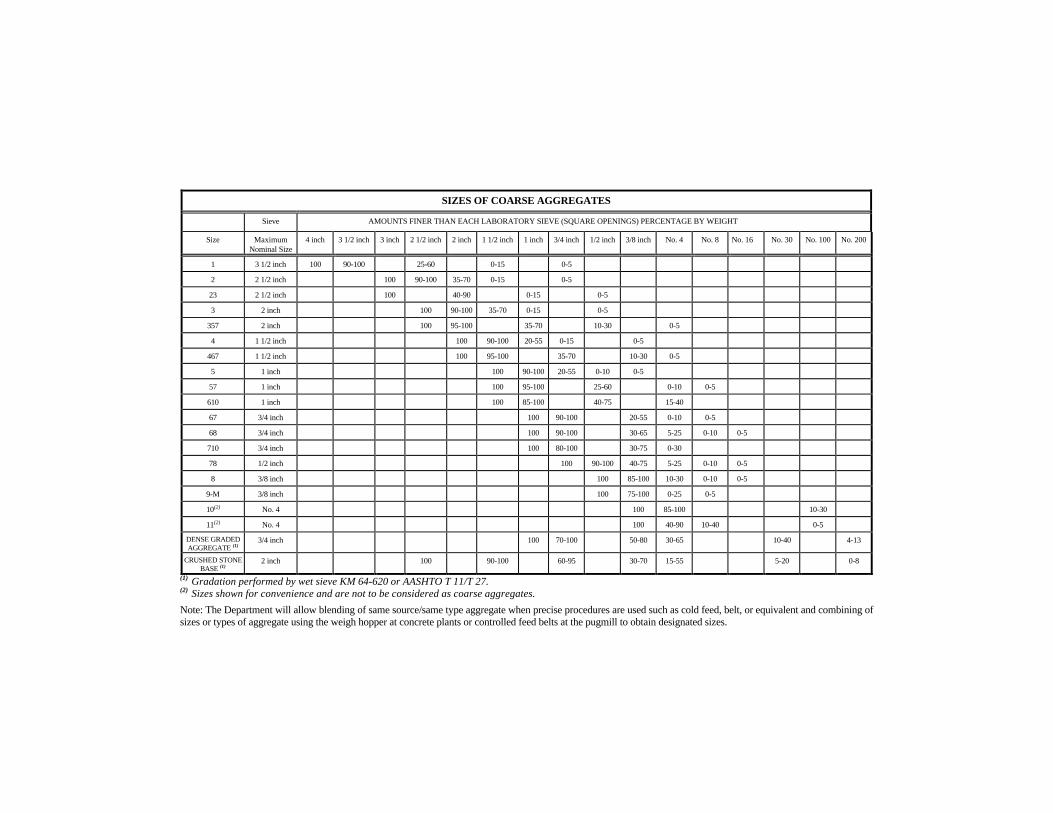
(1) Gradation performed by wet sieve KM 64-620 or AASHTO T 11/T 27.(2) Sizes shown for convenience and are not to be considered as coarse aggregates.
Note: The Department will allow blending of same source/same type aggregate when precise procedures are used such as cold feed, belt, or equivalent and combining ofsizes or types of aggregate using the weigh hopper at concrete plants or controlled feed belts at the pugmill to obtain designated sizes.
SIZES OF COARSE AGGREGATES
Sieve AMOUNTS FINER THAN EACH LABORATORY SIEVE (SQUARE OPENINGS) PERCENTAGE BY WEIGHT
Size MaximumNominal Size
4 inch 3 1/2 inch 3 inch 2 1/2 inch 2 inch 1 1/2 inch 1 inch 3/4 inch 1/2 inch 3/8 inch No. 4 No. 8 No. 16 No. 30 No. 100 No. 200
1 3 1/2 inch 100 90-100 25-60 0-15 0-5
2 2 1/2 inch 100 90-100 35-70 0-15 0-5
23 2 1/2 inch 100 40-90 0-15 0-5
3 2 inch 100 90-100 35-70 0-15 0-5
357 2 inch 100 95-100 35-70 10-30 0-5
4 1 1/2 inch 100 90-100 20-55 0-15 0-5
467 1 1/2 inch 100 95-100 35-70 10-30 0-5
5 1 inch 100 90-100 20-55 0-10 0-5
57 1 inch 100 95-100 25-60 0-10 0-5
610 1 inch 100 85-100 40-75 15-40
67 3/4 inch 100 90-100 20-55 0-10 0-5
68 3/4 inch 100 90-100 30-65 5-25 0-10 0-5
710 3/4 inch 100 80-100 30-75 0-30
78 1/2 inch 100 90-100 40-75 5-25 0-10 0-5
8 3/8 inch 100 85-100 10-30 0-10 0-5
9-M 3/8 inch 100 75-100 0-25 0-5
10(2) No. 4 100 85-100 10-30
11(2) No. 4 100 40-90 10-40 0-5
DENSE GRADEDAGGREGATE (1)
3/4 inch 100 70-100 50-80 30-65 10-40 4-13
CRUSHED STONEBASE (1)
2 inch 100 90-100 60-95 30-70 15-55 5-20 0-8
805—16
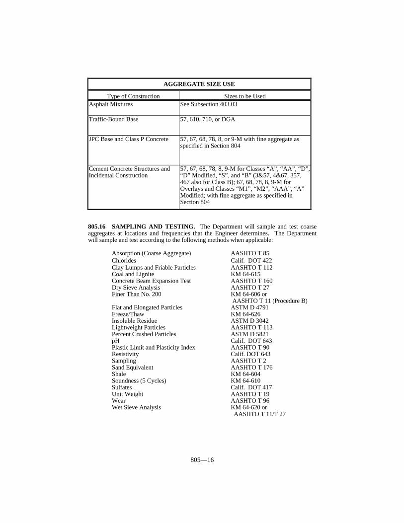
805.16 SAMPLING AND TESTING. The Department will sample and test coarseaggregates at locations and frequencies that the Engineer determines. The Departmentwill sample and test according to the following methods when applicable:
Absorption (Coarse Aggregate) AASHTO T 85Chlorides Calif. DOT 422Clay Lumps and Friable Particles AASHTO T 112Coal and Lignite KM 64-615Concrete Beam Expansion Test AASHTO T 160Dry Sieve Analysis AASHTO T 27Finer Than No. 200 KM 64-606 or
AASHTO T 11 (Procedure B)Flat and Elongated Particles ASTM D 4791Freeze/Thaw KM 64-626Insoluble Residue ASTM D 3042Lightweight Particles AASHTO T 113Percent Crushed Particles ASTM D 5821pH Calif. DOT 643Plastic Limit and Plasticity Index AASHTO T 90Resistivity Calif. DOT 643Sampling AASHTO T 2Sand Equivalent AASHTO T 176Shale KM 64-604Soundness (5 Cycles) KM 64-610Sulfates Calif. DOT 417Unit Weight AASHTO T 19Wear AASHTO T 96Wet Sieve Analysis KM 64-620 or
AASHTO T 11/T 27
AGGREGATE SIZE USE
Type of Construction Sizes to be UsedAsphalt Mixtures See Subsection 403.03
Traffic-Bound Base 57, 610, 710, or DGA
JPC Base and Class P Concrete 57, 67, 68, 78, 8, or 9-M with fine aggregate asspecified in Section 804
Cement Concrete Structures andIncidental Construction
57, 67, 68, 78, 8, 9-M for Classes “A”, “AA”, “D”,“D” Modified, “S”, and “B” (3&57, 4&67, 357,467 also for Class B); 67, 68, 78, 8, 9-M forOverlays and Classes “M1”, “M2”, “AAA”, “A”Modified; with fine aggregate as specified inSection 804
806—1
SECTION 806 ASPHALT MATERIALS
806.01 DECRIPTION. The asphalt materials section covers performance-graded (PG)binders, emulsified asphalts, cut-back emulsions, and liquid asphalt for cold-patchingmixtures. Provide the specified grade of material conforming to the requirements in thissection from suppliers listed in the Department’s List of Approved Materials. Inclusion onthe list of approved suppliers is obtained by following the guidelines of the ApprovedSupplier Certification (ASC) program contained in Kentucky Method (KM) 64-444, byfollowing the guidelines of the Emulsified Asphalt Supplier Certification (EASC) programcontained in KM 64-445, or by pretesting and approval. The Department may approveother types of asphalt materials provided they conform to the requirements of the typespecified in the contract.
806.02 SAMPLING. The Department will sample all asphalt materials according toKM 64-404.
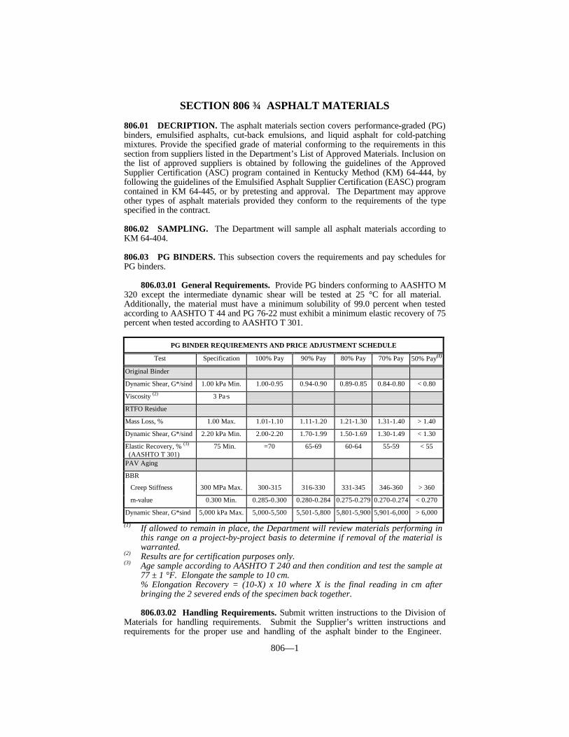
806.03 PG BINDERS. This subsection covers the requirements and pay schedules forPG binders.
806.03.01 General Requirements. Provide PG binders conforming to AASHTO M320 except the intermediate dynamic shear will be tested at 25 °C for all material. Additionally, the material must have a minimum solubility of 99.0 percent when testedaccording to AASHTO T 44 and PG 76-22 must exhibit a minimum elastic recovery of 75percent when tested according to AASHTO T 301.
(1) If allowed to remain in place, the Department will review materials performing inthis range on a project-by-project basis to determine if removal of the material iswarranted.
(2) Results are for certification purposes only.(3) Age sample according to AASHTO T 240 and then condition and test the sample at
77 ± 1 °F. Elongate the sample to 10 cm.% Elongation Recovery = (10-X) x 10 where X is the final reading in cm afterbringing the 2 severed ends of the specimen back together.
806.03.02 Handling Requirements. Submit written instructions to the Division ofMaterials for handling requirements. Submit the Supplier’s written instructions andrequirements for the proper use and handling of the asphalt binder to the Engineer.
PG BINDER REQUIREMENTS AND PRICE ADJUSTMENT SCHEDULE
Test Specification 100% Pay 90% Pay 80% Pay 70% Pay 50% Pay(1)
Original Binder
Dynamic Shear, G*/sind 1.00 kPa Min. 1.00-0.95 0.94-0.90 0.89-0.85 0.84-0.80 < 0.80
Viscosity (2) 3 Pa·s
RTFO Residue
Mass Loss, % 1.00 Max. 1.01-1.10 1.11-1.20 1.21-1.30 1.31-1.40 > 1.40
Dynamic Shear, G*/sind 2.20 kPa Min. 2.00-2.20 1.70-1.99 1.50-1.69 1.30-1.49 < 1.30
Elastic Recovery, % (3)
(AASHTO T 301) 75 Min. =70 65-69 60-64 55-59 < 55
PAV Aging
BBR
Creep Stiffness 300 MPa Max. 300-315 316-330 331-345 346-360 > 360
m-value 0.300 Min. 0.285-0.300 0.280-0.284 0.275-0.279 0.270-0.274 < 0.270
Dynamic Shear, G*sind 5,000 kPa Max. 5,000-5,500 5,501-5,800 5,801-5,900 5,901-6,000 > 6,000

806—2
Include tank requirements, construction equipment requirements, and storage and mixingtemperature requirements. Submit material test data and a certification of conformanceprior to shipping material.
806.03.03 Modification. Use only organic, non-particulate modifiers. All bindersare to be homogeneous blends. Include a statement of the type of modification with allsamples submitted to the Division of Materials for testing and certification. Circulate oragitate the modified asphalt binders in the storage tank as specified in the Supplier’shandling procedures. Obtain the Engineer’s approval for the means of circulation. Do notuse in-line blending at the asphalt plant.
806.04 EMULSIFIED ASPHALTS. This subsection covers emulsified asphalts of thefollowing grades:
• RS-1 • RS-2 • SS-1 • SS-1h• AE-200 • HFRS-2 • CRS-2 • HFMS-2
806.04.01 General Requirements. Furnish emulsified asphalts that arehomogeneous, showing no separation of asphalt during normal handling or storage. TheEngineer will reject emulsified asphalt that has been frozen.
806.04.02 Specific Requirements for Grades RS-1, RS-2, SS-1, HFRS-2,HFMS-2, and SS-1h. Conform to AASHTO M 140 with the following exceptions:
1) The cement-mixing test is not required.2) The penetration of Grade SS-1h residue is not to exceed 100.3) The storage stability of emulsions is not to exceed 1.5%.
806.04.03 Testing of Grades RS-1, RS-2, SS-1, HFRS-2, HFMS-2, and SS-1h. Perform tests according to AASHTO T 59. Use Tyrone Formation limestone as thereference aggregate for the coating test.
EMULSIFIED ASPHALT REQUIREMENTS AND PRICE ADJUSTMENTSCHEDULE
Test Grade Specification 100% Pay 90% Pay 80% Pay 70% Pay 50% Pay(1)
Viscosity, RS-1, 15-17 12-14 9-11 ≤ 8
Saybolt Furol SS-1, SS-1h 20-100 18-110 111-120 121-130 131-140 ≥ 141
@ 77 ºF, s HFMS-2 ≥ 100 ≥ 90 80-89 70-79 60-69 ≤ 59
AE-200 ≥ 50 ≥ 45 40-44 35-39 30-34 ≤ 29
Viscosity, RS-2, 60-64 55-59 50-54 ≤ 49
Saybolt Furol HFRS-2 75-400 65-440 441-480 481-520 521-560 ≥ 561
@ 122 ºF, s 85-89 80-84 75-79 ≤ 74
CRS-2 100-400 90-440 441-480 481-520 521-560 ≥ 561
Residue by SS-1, SS-1h ≥ 57 ≥ 28 27 26 25 ≤ 24
Distillation, % RS-1 ≥ 55 ≥ 54 51-53 48-50 45-47 ≤ 44
CRS-2, HFMS-2 ≥ 65 ≥ 64 61-63 58-60 55-57 ≤ 54
HFRS-2, RS-2 ≥ 63 ≥ 62 59-61 56-58 53-55 ≤ 52
AE-200 ≥ 60 ≥ 59 56-58 53-55 50-52 ≤ 49
Oil Distillates, CRS-2 0-5 0-6 7-10 11-14 15-18 ≥ 19
% AE-200 0-6 0-7 8-10 11-13 14-16 ≥ 17

806—3
(1) If allowed to remain in place, the Department will review materials in this range ona project-by-project basis to determine if removal of the material is warranted.
EMULSIFIED ASPHALT REQUIREMENTS AND PRICE ADJUSTMENTSCHEDULE (CONTINUED)
Test Grade Specification 100% Pay 90% Pay 80% Pay 70% Pay 50% Pay(1)
Demulsibility, RS-1, RS-2, ≥ 60 ≥ 57 51-56 45-50 39-44 ≤ 38
% HFRS-2
CRS-2 ≥ 40 ≥ 38 34-37 30-33 26-29 ≤ 25
Residue 34-36 31-33 28-30 ≤ 27
Penetration SS-1h 40-100 37-108 109-120 121-130 131-140 ≥ 141
SS-1, RS-1, 87-91 82-86 77-81 ≤ 76
RS-2, HFRS-2, 100-200 92-216 217-225 226-235 236-245 ≥ 246
HFMS-2
87-91 82-86 77-81 ≤ 76
CRS-2 100-250 92-270 271-275 276-280 281-285 ≥ 286
Particle Charge Not Applicable – Determines Only
CRS-2
Positive
That Emulsion is Cationic
Float Test AE-200, HFRS-2, ≥ 1,200 ≥ 1,100 800-1,099 500-799 300-499 ≤ 299
@ 140 ºF, s HFMS-2
Coating Test, % AE-200, HFMS-2 ≥ 95 ≥ 90 85-89 80-84 75-79 ≤ 74
Sieve, % RS-1, RS-2,
HFRS-2, CRS-2, ≤ 0.10 ≤ 0.30 0.31-0.45 0.46-0.60 0.61-0.75 ≥ 0.76
SS-1, SS-1h
Ductility, cm SS-1, SS-1h,
@ 77 ºF RS-2, CRS-2, ≥ 40 ≥ 38 35-37 32-34 29-31 ≤ 28
RS-1, HFRS-2,
HFMS-2
Storage SS-1, SS-1h,
Stability, % (2) RS-1, RS-2,
CRS-2, HFRS-2, ≤ 1.5
AE-200
Solubility in SS-1, SS-1h,
Trichloro- RS-1, RS-2, ≥ 97.5
ethylene, % (2) CRS-2, AE-200,
HFRS-2(1) If allowed to remain in place, the Department will review materials performing in
this range on a project-by-project basis to determine if removal of the material iswarranted.
(2) Results are for certification purposes only.
806.04.04 Specific Requirements for Grades AE-200 and CRS-2. Conform to theEmulsified Asphalt Requirements Schedule.
806.04.05 Testing of Grades AE-200 and CRS-2. Perform tests according toAASHTO T 59.

806—4
806.05 POLYMER ASPHALT EMULSIONS (CRS-2P). These materials aredesigned to be used in seal coats and stress-absorbing membrane interlayers (SAMI). Make the polymer modification to the base asphalt before the emulsification process.Ensure that polymer-modified asphalt emulsions conform to the requirements in thePolymer Asphalt Emulsion (CRS-2P) Requirements and Price Adjustment Schedule.
POLYMER ASPHALT EMULSION (CRS-2P) REQUIREMENTS ANDPRICE ADJUSTMENT SCHEDULE
Test(1) Specification 100% Pay 90% Pay 80% Pay 70% Pay 50% Pay(2)
Viscosity @ 122 ºF, SFS(3) 50-54 45-49 40-44 ≤ 39
60-400 55-480 481-520 521-560 561-600 = 600
80-84 70-79 60-69 ≤ 59
Viscosity @ 122 ºF, SFS(4) 100-400 85-480 481-520 521-560 561-600 ≥ 601
Distillation: % Oil 0-3.0 0-5.0 5.1-8.0 8.1-10.0 10.1-12.0 ≥ 12.1
% Residue(5) ≥ 65 ≥ 63 60.0-62.9 57.0-59.9 55.0-56.9 ≤ 54.9
Sieve, % ≤ 0.1 ≤ 0.35 0.36-0.50 0.51-0.70 0.71-0.90 ≥ 0.91
Residue Penetration @ 77 ºF 80-84 75-79 70-74 ≤ 69
100-200 85-230 231-240 241-250 251-260 ≥ 261
Residue Ductility @ 39 ºF, cm ≥ 15 ≥ 13 11.0-12.9 9.0-10.9 7.0-8.9 ≤ 6.9
% Recovery @ 39 ºF (6) ≥ 55 ≥ 50 45.0-49.9 40.0-44.9 35.0-39.9 ≤ 34.9
(AASHTO T 301)
% Demulsibility:
0.8% Sodium Diocytl ≥40 ≥35 32-34 29-31 26-28 ≤ 25
Sulfosuccinate
Particle Charge Positive
Storage Stability, % (7)(8) ≤ 1.0
Solubility, % (7) ≥ 97.5
Softening Point of Residue, > 100
ºF (7) (AASHTO T 53)(1) Test according to AASHTO T 59 except where noted.(2) If allowed to remain in place, the Department will review materials performing in
this range on a project-by-project basis to determine if removal of the material iswarranted.
(3) Applies only if the residue from distillation is 72% or more.(4) Applies only if the residue from distillation is less than 72%.(5) Modify AASHTO T 59 to provide a maximum distillation temperature of 400 ± 5 °F
for at least 20 minutes.(6) Condition the sample and test the sample at 39 ± 2 °F. Elongate the sample to 10
cm. % Elongation Recovery = (10-X) x 10 where X is the final reading in cm afterbringing the two severed ends of the specimen back together.
(7) Results are for certification purposes only.(8) Provide a material that, after standing undisturbed for 24 hours, shows a uniform,
brown color throughout.
806.06 PRIMER L. Prepare Primer L by compounding a suitable solvent and waterwith a petroleum asphalt.

806—5
806.06.01 Requirements. Furnish Primer L that is of such consistency that it can bespread uniformly with a pressure distributor and that it will adhere to all types ofaggregates or asphalt bases, even in the presence of water. Ensure that the material iscapable of penetrating the existing surfaces so as to plug capillary voids, to coat and bonddust and loose mineral particles, and thus harden or toughen the surface and promoteadhesion between it and the superimposed treatment or construction. In addition, ensurethat Primer L complies with the requirements of the Primer L Requirements and PriceAdjustment Schedule.
PRIMER L REQUIREMENTS AND PRICE ADJUSTMENT SCHEDULE
Test Specification 100% Pay 90% Pay 80% Pay 70% Pay 50% Pay(1)
Viscosity, Saybolt-Furol @ 77 ºF, s 21-26 16-20 11-15 ≤ 10(AASHTO T 59) 30-100 27-110 111-120 121-130 131-140 ≥ 141
Water Content, % 1.5-1.9 1.0-1.4 0.5-0.9 ≤ 0.4
(AASHTO T 55) 3-8 2.0-9 10-11 12-13 14-15 ≥ 16
Asphalt Content, % (AASHTO T 78) ≥ 45 ≥ 44 40-43 36-39 32-35 ≤ 31
Stone Coating Test, % (AASHTO T 59) 100 100 95 90 85 ≤ 80
Residue Test, Float @ 122 ºF, s ≥ 80 ≥ 75 70-74 60-69 50-59 ≤ 49
(AASHTO T 50)
Solubility in Trichloroethylene(2) ≥ 97.5
(AASHTO T 44)(1) If allowed to remain in place, the Department will review materials performing in
this range on a project-by-project basis to determine if removal of the material iswarranted.
(2) Results are for certification purposes only.
806.07 ASPHALT COATING AND PAVING FOR METAL PIPE, PIPEARCHES, AND ARCHES. These requirements apply to all corrugated metal pipe, pipearches, and arches that are required to be asphalt-coated or coated and paved, except field-assembled structural plate pipe and pipe arches as specified in Section 612.
806.07.01 Asphalt Coating Material. Furnish asphalt coating material conformingto AASHTO M 190 and, in addition, the following physical properties:
1) Penetration at 32 °F, ASTM D 5 or AASHTO T 49 - 20 minimum at 200 g for60 seconds.
2) Penetration at 77 °F, ASTM D 5 or AASHTO T 49 - 35 to 55 at 100 g for 5seconds.
3) Flash Point, ASTM D 92 or AASHTO T 48 - 450 °F minimum.4) Specific Gravity, ASTM D 70 or AASHTO T 229 - 0.98 minimum.5) Softening Point, ASTM D 36 or AASHTO T 53 – 200-230 °F.
The Department will obtain random samples of the asphalt coating material foranalysis. The Department will reject all material not conforming to AASHTO M 190 andthis subsection.
806.08 LIQUID ASPHALT FOR COLD-PATCHING MIXTURES. Ensure thatthe liquid asphalt material furnished under this subsection provides satisfactory coatingproperties, workability, and adherence characteristics for patching during cold and dampweather in either asphalt or concrete pavement surfaces. Furnish patching mixtures madewith liquid asphalt, KP-2 or KP-4, that is capable of being stored for at least six monthsbefore being used and that is readily workable at all ambient temperatures above 25 °F.
Provide with each shipment of material certified test results showing that the

806—6
materials furnished conform to the following KP-2 or KP-4 Requirements table, asapplicable. Additionally, take a one-gallon sample from one transport as specified in theMaterials Field Sampling and Testing Manual from the Department’s Division ofMaterials. Ship the sample to the Division of Materials by any expedient means oftransport. Obtain the Division of Materials’ approval before using the liquid asphalt.
KP-2 REQUIREMENTSProperty Test Method ValueFlash Point, °F AASHTO T 79 200 min.Water, % AASHTO T 55 0.2 max.Distillate Test, % to 437 °F None to 500 °F ASTM D 402 0 – 5.0 to 600 °F 0 – 25.0
Residue From Distillate @ 680 °F, % ASTM D 402 72.0 – 95.0Penetration ASTM D 5 200 min.Ductility, cm (39 °F, one cm/min) ASTM D 113 100 min.Solubility in Trichloroethylene, % ASTM D 2042 99 min.Stripping Test, % Uncoated Area AASHTO T 182 5 max.
KP-4 REQUIREMENTSProperty Test Method ValueFlash Point, °F AASHTO T 79 200 °F minimumViscosity, Saybolt Furol @ 122 °F, s AASHTO T 72 100-500(1)
Coating Test, % Coated Area AASHTO T 182 95.0 min.Residue From Distillate, % AASHTO T 59 72.0 min.Oil Distillate, % AASHTO T 59 3.0 - 7.0Penetration ASTM D 5 200 min.Solubility in Trichloroethylene, % ASTM D 2042 98 min.
(1) The Department may accept higher values if the material is pumpable.
806.09 FIELD TOLERANCES. The Department, according to established criteria,allows tolerance limits to be applied to field samples. These limits are incorporated intothe price adjustment schedules. These tolerances are for field samples only and will notapply to certification samples.
806.10 ACCEPTANCE. The Department will normally perform field qualityacceptance testing on samples obtained at the project site or Contractor’s storage facility. When required by the Department, the asphalt supplier shall send, at his expense,representative samples of materials stored at the source terminal or refinery to theDepartment’s Division of Materials.
When the Department accepts asphalt materials by pretesting and certification,provide two copies of the bill-of-lading/load ticket with each hauling unit. The bill-of-lading/load ticket will contain the material’s lot number, a statement of the quantity ofmaterials within each load by weight and volume, and other information as required byKM 64-444 or KM 64-445. The Contractor and Department’s representative will eachreceive copies at the point of delivery. Also, forward a copy of the bill-of-lading/loadticket directly to the Department’s Division of Materials as soon as practical followingshipments.
Do not use asphalt materials that are not properly covered by certification or otherwisetested and approved by the Department. When asphalt materials not of the specifiedgrade, not appropriately certified, or not conforming to the applicable requirements whentested become incorporated into projects, the Engineer will, according to Section 105,

806—7
evaluate the work affected and require adjustment of pay quantities or corrective work asdeemed appropriate.
806.10.01 Acceptance of Non-Specification Asphalt Materials. Furnish asphaltmaterials purchased for Department work conforming to the requirements of this section. The Department will apply the following procedures only when reasonably acceptablework has been produced using the material in question, as provided in Subsection 105.04.When the use of non-specification material results in an inferior or unsatisfactory product,remove and replace the material at no expense to the Department, or at the Vendor’sexpense when materials are purchased directly by the Cabinet.
The Department may accept, at a reduced Contract price, asphalt materials not of thespecified grade, not appropriately certified, or not conforming to the applicablerequirements when check-tested after an evaluation of the work. However, the Departmentwill not consider these procedures as a means to continue accepting non-specificationmaterial.
The Department will determine the price adjustment based on the delivered cost of thematerial.
When the material is not of the specified grade or not appropriately certified, theDepartment may deduct the full cost of the material.
When the material fails to conform to the applicable requirements, the Departmentwill normally make deductions according to the pay schedules in this section. As providedin Subsection 806.09, the Department has established field tolerances for determining theacceptability of failing material at no price deduction. The Department will determine thefrequency of check-sampling and testing on pretested material. The Department will makedeductions for failing test results based on the average of two check samples representingthe material in question. When a sample fails on two or more tests, the Department mayadd the deductions, but the total deduction will not exceed 100 percent.
806.11 TIME LIMITATION ON APPROVALS. The Department will test materialsin storage at the terminal as deemed necessary. Additionally, the Department will requirethe retesting, and re-approval, of materials not incorporated into the work within onemonth (2 months for PG binders) of the shipment date.

807—1
SECTION 807 JOINT MATERIALS
807.01 DESCRIPTION. This section covers joint sealers and joint fillers of varioustypes. The Department may approve other types of joint materials provided they conformto the requirements of the type specified in the Contract.
807.02 SAMPLING. The Department will sample all materials according to theMaterials Field Sampling and Testing Manual from the Department’s Division ofMaterials.
807.03 JOINT SEALERS.
807.03.01 Hot-Poured, Elastic Joint Sealers. Furnish hot-poured, elastic jointsealers that meet or exceed the requirements of ASTM D 6690, Type II and the followingtable. Provide a certification of conformance with each lot of sealer.
(1) If allowed to remain in place, the Department will review materials performing inthis range on a project-by-project basis to determine if removal of the material iswarranted.
807.03.02 Preformed, Compression Joint Sealers With Lubricant. Furnishpreformed, compression joint sealers of approved shapes and sizes for the applicable jointsto be sealed. Furnish sealers and lubricant that conform to the following requirements asapplicable.
A) Sealers. Furnish sealers that conform to ASTM D 2628 with the followingexceptions and additions: 1) The Department’s Division of Materials and Division of Bridge Design will
approve the configuration of compression joint sealers. Approved sealerswill be placed on the Department’s List of Approved Materials. Obtain theDepartment’s approval for sealers not on the List of Approved Materialsbefore shipping to the project.
2) Furnish sealers designed to be substantially solid at closure (when fullycompressed). Closure of a sealer should occur at 50 to 70 percent of itsoriginal width.
3) Ensure that the manufacturer provides sealers accurately marked at 12-inchintervals to determine elongation after installation.
4) Ensure that sealers are designed so that, when compressed, the centerportion of the top surfaces will not protrude upward above the originalelevation of the sealer.
5) The Department will subject sealers to a compression-deflection testaccording to KM 64-409. Ensure that the sealer displays a minimum forceper unit area of 3 psi at 15-percent deflection and a maximum force per unitarea of 40 psi at 50-percent deflection.
HOT-POURED, ELASTIC JOINT SEALER REQUIRMENTS AND PRICEADJUSTMENT SCHEDULE
Test Specification 100% Pay 90 % Pay 80 % Pay 70% Pay 50% Pay(1)
Cone Penetration, 90 max. 91-92 93-94 95-96 97-98 = 99Non-immersedFlow, mm 3.0 max. 3.1-3.2 3.3-3.4 3.5-3.6 3.7-3.8 = 3.9
Resilience, % 60 min. 59-58 57-56 55-54 53-52 = 51Bond, Non-immersed Pass

807—2
6) Ensure that the sealers used in JPC pavement comply with the applicableStandard Drawings.
7) Ensure that the uncompressed depth of all sealers is at least equal to theuncompressed sealer width, unless the design of the sealer prevents twistingor misalignment of the sealer during or after installation.
8) Ensure each lot number is accompanied by a certification statingconformance with this Subsection.
B) Lubricant. As recommended by the sealer manufacturer, provide lubricant thatis compatible with the sealer, concrete, steel and meets the following criteria:
1) Concrete Pavements. Obtain certification from the manufacturer stating thematerial conforms to ASTM D 2835.
2) Bridges. Obtain certification from the manufacturer stating the materialconforms to ASTM D 4070.
807.03.03 Preformed, Expansion Joint Strip Seals With Lubricant Adhesive.Furnish preformed, expansion joint strip sealers of approved design for the applicablejoints to be sealed. Furnish sealers and lubricant adhesives that conform to thefollowing requirements as applicable.
A) Sealers. Furnish sealers that conform to ASTM D 5973 with the followingexceptions and additions:
1) The Department’s Division of Materials and Division of Bridge Design will
approve the design of the expansion joint strip sealers. Approved sealerswill be placed on the Department’s List of Approved Materials. Obtain theDepartment’s approval for sealers not on the List of Approved Materialsbefore shipping to the project.
2) Ensure that the manufacturer provides sealers accurately marked at 12-inchintervals to determine elongation after installation.
3) Ensure that the sizes of sealers used in JPC pavement comply with theapplicable Standard Drawings.
4) Ensure each lot number is accompanied by a certification statingconformance with this Subsection.
B) Lubricant Adhesive. As recommended by the sealer manufacturer, providelubricant adhesive that is compatible with the sealer, concrete, and steel. Obtaincertification from the manufacturer stating the material conforms to ASTM D 4070.
807.03.04 Joint Sealer for Rigid Pipe.
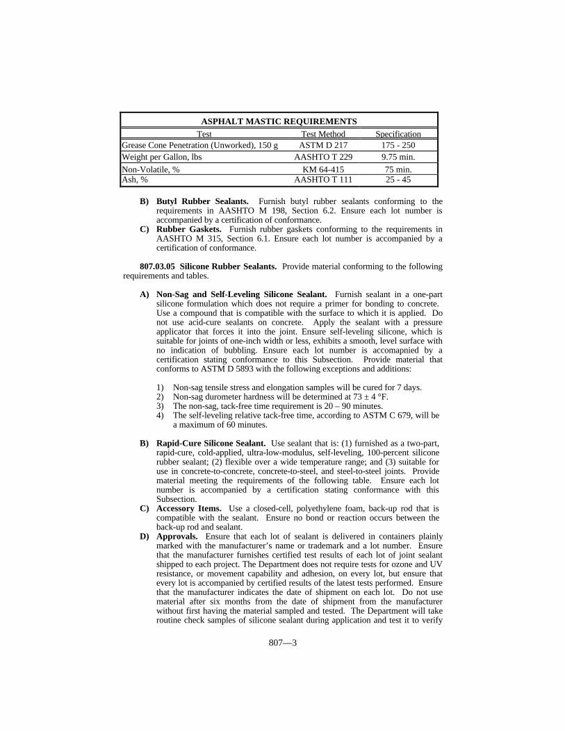
A) Asphalt Mastic. Furnish asphalt mastic joint sealing material consisting of asmooth, uniform mixture of asphalt material, solvent, and filler. Use filler thatconsists essentially of cellulose fiber. Ensure that the mixture is applicable, bymeans of a trowel or caulking gun, without pulling or drawing, and does not sagor flow when applied to metal, concrete, or vitrified clay surfaces. Furnish acompound capable of withstanding freezing and not exhibiting any tendency toseparate or otherwise deteriorate while in storage. Ensure each lot number isaccompanied by a certification stating conformance with this Subsection.
When tested according to KM 64-416, ensure that the compound sets to atough, plastic coating and does not shrink, crack, or loosen from the surface. Inaddition, furnish material conforming to the following table:
807—3
B) Butyl Rubber Sealants. Furnish butyl rubber sealants conforming to therequirements in AASHTO M 198, Section 6.2. Ensure each lot number isaccompanied by a certification of conformance.
C) Rubber Gaskets. Furnish rubber gaskets conforming to the requirements inAASHTO M 315, Section 6.1. Ensure each lot number is accompanied by acertification of conformance.
807.03.05 Silicone Rubber Sealants. Provide material conforming to the followingrequirements and tables.
A) Non-Sag and Self-Leveling Silicone Sealant. Furnish sealant in a one-partsilicone formulation which does not require a primer for bonding to concrete. Use a compound that is compatible with the surface to which it is applied. Donot use acid-cure sealants on concrete. Apply the sealant with a pressureapplicator that forces it into the joint. Ensure self-leveling silicone, which issuitable for joints of one-inch width or less, exhibits a smooth, level surface withno indication of bubbling. Ensure each lot number is accomapnied by acertification stating conformance to this Subsection. Provide material thatconforms to ASTM D 5893 with the following exceptions and additions:
1) Non-sag tensile stress and elongation samples will be cured for 7 days. 2) Non-sag durometer hardness will be determined at 73 ± 4 °F. 3) The non-sag, tack-free time requirement is 20 – 90 minutes. 4) The self-leveling relative tack-free time, according to ASTM C 679, will be
a maximum of 60 minutes.
B) Rapid-Cure Silicone Sealant. Use sealant that is: (1) furnished as a two-part,rapid-cure, cold-applied, ultra-low-modulus, self-leveling, 100-percent siliconerubber sealant; (2) flexible over a wide temperature range; and (3) suitable foruse in concrete-to-concrete, concrete-to-steel, and steel-to-steel joints. Providematerial meeting the requirements of the following table. Ensure each lotnumber is accompanied by a certification stating conformance with thisSubsection.
C) Accessory Items. Use a closed-cell, polyethylene foam, back-up rod that iscompatible with the sealant. Ensure no bond or reaction occurs between theback-up rod and sealant.
D) Approvals. Ensure that each lot of sealant is delivered in containers plainlymarked with the manufacturer’s name or trademark and a lot number. Ensurethat the manufacturer furnishes certified test results of each lot of joint sealantshipped to each project. The Department does not require tests for ozone and UVresistance, or movement capability and adhesion, on every lot, but ensure thatevery lot is accompanied by certified results of the latest tests performed. Ensurethat the manufacturer indicates the date of shipment on each lot. Do not usematerial after six months from the date of shipment from the manufacturerwithout first having the material sampled and tested. The Department will takeroutine check samples of silicone sealant during application and test it to verify
ASPHALT MASTIC REQUIREMENTSTest Test Method Specification
Grease Cone Penetration (Unworked), 150 g ASTM D 217 175 - 250Weight per Gallon, lbs AASHTO T 229 9.75 min.Non-Volatile, % KM 64-415 75 min.Ash, % AASHTO T 111 25 - 45

807—4
the material’s acceptability. Provide equipment suitable for obtainingrepresentative check samples from the silicone sealant at a frequency determinedby the Materials Field Sampling and Testing Manual from the Department’sDivision of Materials.
The Engineer may accept the foam back-up rod on the project by visualinspection.
Use rapid-cure silicone sealant conforming to the following table:
(1) Allow a cure time of 48 hours at 77 °F and 50 % relative humidity.
807.04 JOINT FILLERS.
807.04.01 General. Furnish preformed fillers in a single piece for the full depth andwidth required for the joint unless otherwise authorized. When the Engineer authorizes theuse of more than one piece for a joint, fasten the abutting ends securely, and hold themaccurately to shape.
807.04.02 Preformed Sponge Rubber and Cork Expansion Joint Fillers. Furnishpreformed sponge rubber and cork joint fillers that conform to AASHTO M 153 for Type I(sponge rubber), Type II (cork), or Type III (self-expanding cork) as specified. Ensureeach lot number is accompanied by a certification of conformance.
807.04.03 Preformed Asphalt Expansion Joint Fillers. Furnish preformed asphaltjoint fillers that conform to AASHTO M 213. Ensure each lot number is accompanied bya certification of conformance.
807.04.04 Oil Asphalt Joint Fillers. Furnish oil asphalt joint fillers that conform tothe following requirements:
1) Flash Point (AASHTO T 48) - 446 °F minimum;2) Softening Point (AASHTO T 53) - 167 - 185 °F;3) Penetration (AASHTO T 49):
• at 77 °F, 100 g, 5 s - 30 – 45,• at 32 °F, 200 g, 60 s - 10 minimum,• at 115 °F, 50 g, 5 s - 90 maximum;
4) Loss on Heating (AASHTO T 47) - 1.0 percent, maximum;5) Penetration (AASHTO T 49) at 77 °F, 100 g, 5 s, of residue from evaporation
loss compared to original penetration before heating - 80 percent minimum;6) Ductility (AASHTO T 51) at 77 °F - 30 mm minimum;7) Matter Soluble in Trichloroethylene (AASHTO T 44) - 99.0 percent minimum;
and8) Ensure that the asphalt filler is free from water and does not foam when heated to
the flash point.
RAPID-CURE SILICONE JOINT SEALANT REQUIREMENTSTest Test Method Specification
Extrusion Rate, g/minute ASTM C 1183 200 – 550Non-Volatile Content, % ASTM C 792 93 min.Relative Tack-Free Time, minutes ASTM C 679 20 max.Elongation, %(1) ASTM D 412 600 min.Tensile Stress (100% elongation), psi(1) ASTM D 412 3 – 20Tensile Adhesion, % ASTM D 5329 600 min.Bond (10 cycles at 100%and –50%) ASTM C 719 No FailureAccelerated Weathering ASTM C 793 No Change

807—5
Ensure each lot number is accompanied by a certification of conformance.
807.05 FIELD TOLERANCES. The Department, according to established criteria, willallow tolerance limits to be applied to field samples. These limits are incorporated into theprice adjustment schedules. These tolerances are for field samples only and will not applyto certification samples.
807.06 ACCEPTANCE. The Department will normally perform field quality acceptancetesting on samples obtained at the project site or Contractor’s storage facility. Whenrequired by the Department, the sealer supplier shall send, at his expense,representative samples of materials stored at the source to the Department’s Divisionof Materials.
When the Department accepts materials by pretesting and certification, providetwo copies of the bill-of-lading/load ticket with each delivered unit. The bill-of-lading/load ticket, at a minimum, will contain the material’s lot number and astatement of the quantity of materials within each load. In addition, materialspretested by the Department will include the assigned KMIMS identification numberin the shipment documentation. The Contractor and Department’s representativewill each receive copies at the point of delivery.
Do not use materials that are not properly covered by certification or otherwise testedand approved by the Department. When materials not appropriately certified or notconforming to requirements when tested become incorporated into projects, theEngineer will, according to Section 105, evaluate the work affected and requireadjustment of pay quantities or corrective work as deemed appropriate.
807.06.01 Acceptance of Non-Specification Joint Materials. Furnish jointmaterials purchased for Department work conforming to the requirements of this section. The Department will apply the following procedures only when reasonably acceptablework has been produced using the material in question, as provided in Subsection 105.04. When the use of non-specification material results in an inferior or unsatisfactory product,remove and replace the material at no expense to the Department, or at the Vendor’sexpense when materials are purchased directly by the Cabinet.
The Department may accept, at a reduced Contract price, joint materials notappropriately certified, or not conforming to the applicable requirements when check-tested, after an evaluation of the work. However, the Department will not consider theseprocedures as a means to continue accepting non-specification material.
The Department will determine the price adjustment based on the delivered cost of thematerial.
When the material is not appropriately certified, the Department may deduct thefull cost of the material.
When the material fails to conform to the applicable requirements, theDepartment will normally make deductions according to the pay schedules includedin this section. As provided in Subsection 807.04, the Department has establishedfield tolerances for determining the acceptability of failing material at no pricededuction. The Department will determine the frequency of check-sampling andtesting on pretested material. The Department will make deductions for failing testresults based on the average of two check samples representing the material inquestion. When a sample fails on two or more tests, the Department may add thedeductions, but the total deduction will not exceed 100 percent.

807—6
(1) If allowed to remain in place, the Department will review the materials performing in this range on a project-by-project basis to determine if removal of the material is warranted.
(2) For self-leveling silicone only. (3) For non-sag silicone only.(4) For certification purposes only.
NON-SAG AND SELF-LEVELING SILICONE SEALANT REQUIREMENTS AND PRICE ADJUSTMENT SCHEDULETest Specification 100% Pay 90% Pay 80% Pay 70% Pay 50% Pay(1)
Tack-Free Time, minutes Non-Sag 15-19 12-14 9-11 6-8 ≤ 5
20-90 91-95 96-98 99-101 102-104 ≥ 105Self-Leveling 300 max. 301-310 311-320 321-330 331-340 = 341
Relative Tack-Free Time, minutes(2) 60 max. 61-65 66-68 69-71 72-74 = 75Durometer Hardness, 8 7 6 5 ≤ 4Shore A (7-Day Cure) 10-25 27 28 29 30 ≥ 31Tensile Stress (150% Elongation7-Day Cure), psi 45 max. 46-50 51-53 54-56 57-59 ≥ 60Elongation (7-Day Cure), % 600 min. ≥ 550 525-549 500-524 475-499 ≤ 474Slump, inches(3) 0.30 max. = 0.32 0.33-0.34 0.35-0.37 0.38-0.40 = 0.41Non-Volatile Content, % 90 min. = 90 88-89 86-87 84-85 = 83Flow(4) No flowExtrusion Rate, inches3/minute(4) = 3.5Accelerated Weathering(4) No changeBond(4) No failureShelf Life 6 months

807—7
807.07 TIME LIMITATION ON APPROVALS. The Department will test materialsin storage at the Contractor’s site as deemed necessary. Additionally, the Department willrequire the retesting, and re-approval, of materials not incorporated into the workaccording to the time limitations specified in the Materials Field Sampling and TestingManual from the Department’s Division of Materials.
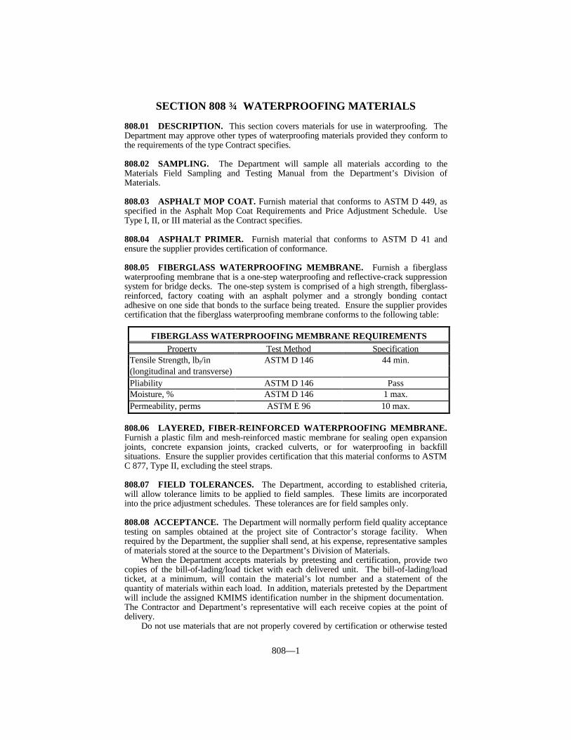
808—1
SECTION 808 WATERPROOFING MATERIALS
808.01 DESCRIPTION. This section covers materials for use in waterproofing. TheDepartment may approve other types of waterproofing materials provided they conform tothe requirements of the type Contract specifies.
808.02 SAMPLING. The Department will sample all materials according to theMaterials Field Sampling and Testing Manual from the Department’s Division ofMaterials.
808.03 ASPHALT MOP COAT. Furnish material that conforms to ASTM D 449, asspecified in the Asphalt Mop Coat Requirements and Price Adjustment Schedule. UseType I, II, or III material as the Contract specifies.
808.04 ASPHALT PRIMER. Furnish material that conforms to ASTM D 41 andensure the supplier provides certification of conformance.
808.05 FIBERGLASS WATERPROOFING MEMBRANE. Furnish a fiberglasswaterproofing membrane that is a one-step waterproofing and reflective-crack suppressionsystem for bridge decks. The one-step system is comprised of a high strength, fiberglass-reinforced, factory coating with an asphalt polymer and a strongly bonding contactadhesive on one side that bonds to the surface being treated. Ensure the supplier providescertification that the fiberglass waterproofing membrane conforms to the following table:
808.06 LAYERED, FIBER-REINFORCED WATERPROOFING MEMBRANE.Furnish a plastic film and mesh-reinforced mastic membrane for sealing open expansionjoints, concrete expansion joints, cracked culverts, or for waterproofing in backfillsituations. Ensure the supplier provides certification that this material conforms to ASTMC 877, Type II, excluding the steel straps.
808.07 FIELD TOLERANCES. The Department, according to established criteria,will allow tolerance limits to be applied to field samples. These limits are incorporatedinto the price adjustment schedules. These tolerances are for field samples only.
808.08 ACCEPTANCE. The Department will normally perform field quality acceptancetesting on samples obtained at the project site of Contractor’s storage facility. Whenrequired by the Department, the supplier shall send, at his expense, representative samplesof materials stored at the source to the Department’s Division of Materials.
When the Department accepts materials by pretesting and certification, provide twocopies of the bill-of-lading/load ticket with each delivered unit. The bill-of-lading/loadticket, at a minimum, will contain the material’s lot number and a statement of thequantity of materials within each load. In addition, materials pretested by the Departmentwill include the assigned KMIMS identification number in the shipment documentation. The Contractor and Department’s representative will each receive copies at the point ofdelivery.
Do not use materials that are not properly covered by certification or otherwise tested
FIBERGLASS WATERPROOFING MEMBRANE REQUIREMENTSProperty Test Method Specification
Tensile Strength, lbf/in ASTM D 146 44 min.(longitudinal and transverse)Pliability ASTM D 146 PassMoisture, % ASTM D 146 1 max.Permeability, perms ASTM E 96 10 max.
808—2
and approved by the Department. When materials not appropriately certified or notconforming to the applicable requirements when tested become incorporated into projects,the Engineer will, according to Section 105, evaluate the work affected and requireadjustment of pay quantities of corrective work as deemed appropriate.
808.09 ACCEPTANCE OF NON-SPECIFICATION WATERPROOFINGMATERIALS. Furnish waterproofing materials purchased for Department workconforming to the requirements of this section. The Department will apply the followingprocedures only when reasonably acceptable work has been produced using the material inquestion, as provided in Subsection 105.04. When the use of non-specification materialresults in an inferior or unsatisfactory product, remove and replace the material at noexpense to the Department, or at the Vendor’s expense when materials are purchaseddirectly by the Cabinet.
The Department may accept, at a reduced Contract price, waterproofing materials notappropriately certified, or not conforming to the applicable requirements when check-tested, after an evaluation of the work. However, the Department will not consider theseprocedures as a means to continue accepting non-specification material.
The Department will determine the price adjustment based on the delivered cost of thematerial.
When the material is not appropriately certified, the Department may deduct the fullcost of the material.
When the material fails to conform to the applicable requirements, the Departmentwill normally make deductions according to the pay schedules included in this section. Asprovided in Section 808.07, the Department has established field tolerances fordetermining the acceptability of failing material at no price deduction. The Departmentwill determine the frequency of check-sampling and testing on pretested material. TheDepartment will make deductions for failing test results based on the average of 2 checksamples representing the material in question. When a sample fails on two or more tests,the Department may add the deductions, but the total deduction will not exceed 100percent.
808.10 TIME LIMITATION ON APPROVALS. The Department will test materialsin storage at the Contractor’s site as deemed necessary. Additionally, the Department willrequire the retesting, and re-approval, of materials not incorporated into the workaccording to the time limitations specified in the Materials Field Sampling and TestingManual from the Department’s Division of Materials.

808—3
ASPHALT MOP COAT REQUIREMENTS AND PRICEADJUSTMENT SCHEDULE
Property Specification 100%Pay 90 %Pay 80 %Pay 70 %Pay 50%Pay(1)
Type I
Softening Point, °F 113-114 111-112 109-110 107-108 = 106115-140 141-142 143-144 145-146 147-148 = 149
Penetration 32 °F 5 min. 5 4 3 2 = 1
48-49 46-47 44-45 42-43 = 41
77 °F
50-100 101-102 103-104 105-106 107-108 =109
115 °F 100 min. 98-99 96-97 94-95 92-93 = 91
Flash Point, °F 450 min. 448-449 446-447 444-445 442-443 = 441
Ductility, cm 30 min. 29 27-28 25-26 23-24 = 22
Solubility, % 99 min. 98 96-97 94-95 92-93 = 91
Type II
Softening Point, °F 143-144 141-142 139-140 137-138 = 136145-170 171-172 173-174 175-176 177-178 = 179
Penetration
32 °F 10 min. 9 8 7 6 = 5
24 23 22 21 = 20
77 °F
25-50 51 52 53 54 = 55
115 °F 130 max. 131 132 133 134 = 135
Flash Point, °F 450 min 448-449 446-447 444-445 442-443 = 441
Ductility, cm 10 min. 9 8 7 6 = 5
Solubility, % 99 min. 98 96-97 94-95 92-93 = 91
Type III
Softening Point, °F 178-179 176-177 174-175 172-173 = 171180-200 201-202 203-204 205-206 207-208 = 209
Penetration 32 °F 10 min. 9 8 7 6 = 5
19 18 17 16 = 15
77 °F
20-40 41 42 43 44 = 45
115 °F 100 max. 101 102 103 104 = 105
Flash Point, °F 475 min. 473-474 471-472 469-470 467-468 = 466
Ductility, cm 2 min. 2 1 0
Solubility, % 99 min. 98 96-97 94-95 92-93 = 91(1) If allowed to remain in place, the Department will review materials performing in
this range on a project-by-project basis to determine if removal of the material iswarranted.

809—1
SECTION 809 STRUCTURAL PLATES FOR PIPES, PIPEARCHES, AND ARCHES
809.01 CORRUGATED STEEL STRUCTURAL PLATE AND ACCESSORIES. Conform to AASHTO M 167. Coat with asphalt material conforming to Subsection806.11. The Department will sample and test the material according to its currentpractices.
809.02 ALUMINUM ALLOY STRUCTURAL PLATE AND ACCESSORIES. Conform to AASHTO M 219. The Department will sample and test the materialaccording to its current practices.

810—1
SECTION 810 PIPE AND PIPE ARCHES
810.01 DESCRIPTION. This section covers the various types of pipe and pipe archesfor use on highway projects.
810.02 APPROVAL. Select pipe or pipe arches supplied by a producer that is listed onthe List of Approved Materials. All producers of pipe and pipe arches must conform toKM 114. These requirements may be obtained from the Division of Materials.
810.03 REINFORCED CONCRETE PIPE.
810.03.01 Pipe Class.
A) Circular. Furnish circular reinforced concrete pipe conforming to AASHTO M170 for Class I, Class II, Class III, Class IV, and Class V. Furnish a D-load pipeconforming to AASHTO M 242 when specified in the Contract.
B) Elliptical. Furnish horizontal and vertical elliptical reinforced concrete pipeconforming to AASHTO M 207 for Class HE-A, Class HE-I, Class HE-II, ClassHE-III, Class HE-IV, Class VE-V, Class VE-VI, Class V-II, Class VE-III, andClass VE-IV.
C) Arch. Furnish reinforced concrete pipe arch conforming to AASHTO M 206 forClass A-II, Class A-III, and Class A-IV.
810.03.02 Aggregates. Conform to Section 804 and 805.
810.03.03 Cement. Use any type conforming to Section 801.
810.03.04 Concrete. Submit concrete mix designs to Central Office Materials.
810.03.05 Extra Protection. Furnish concrete pipe with extra protection to inhibitcorrosion when required by the Standard Drawings for culvert pipe, storm sewer pipe, andentrance pipe. Furnish concrete pipe with extra protection for all other types of pipe whenspecified in the Contract. Use reinforced concrete pipe conforming to Subsection810.03.01 A) for Classes III, IV, and V; Subsection 810.03.01 B) for Classes HE-II, HE-III, HE-IV, VE-II, VE-III, and VE-IV; and Subsection 810.03.01 C) for Classes A-II, A-III, and A-IV. Use concrete having a minimum compressive strength of 6,000 psi at thetime of acceptance. Use Wall B or Wall C as necessary.
When using one line of reinforcement, place it 1/2 of the shell thickness from theinner surface of the pipe. When using 2 lines of reinforcement, place each line so that thenominal protective covering of concrete is one inch from the outer surface of the pipe and 13/4 inches from the inner surface. The Department will allow a variation tolerance of± 1/2 inch with a minimum protective covering of one inch from the inner surface in allcases.
810.03.06 Identification and Markings. Mark pipe sections according to AASHTOM 170 or M 207 as applicable for identification. Additionally, mark “EP” on each sectionof pipe manufactured by the extra protection requirements. When the manufacturer hasmore than one plant, include the plant letter assigned by the Division of Materials after thedate of manufacture as follows:
L-LouisvilleN-LondonProvide shipment approval form containing the following information:
1) Project Number and county.2) Name of Contractor.3) The size, class, and quantity of pipe shipped.

810—2
4) The dates of manufacture of the pipe.5) A signed statement that the pipe is from a tested and approved lot.
The Department will not require the certification on the shipment approval form to benotarized. The Department will not require the information under “Pipe Data” on theapproval form when the manufacturer’s shipment ticket is attached and contains thenecessary information.
The Engineer will check pipe joints to determine if the information on the approvalform or shipping ticket corresponds to the pipe actually received. Correct all discrepanciesbefore using pipe.
810.03.07 Defects. The Department will reject pipe for any of the following reasons.
1) Exposed steel in walls, fractures or cracks passing through the wall, except for asingle end crack that does not exceed the depth of the joint.
2) Defects that indicate imperfect proportioning, mixing, or molding.3) Surface defects indicating honey-combed or open texture.4) Damaged or cracked ends that prevent a satisfactory joint.5) A continuous crack, regardless of its position in the wall of the pipe, having a
surface width of 0.01-inch or more and extending 12 inches or more.
810.04 CORRUGATED METAL PIPE.
810.04.01 Coating Requirements. Use asphalt coating and paving as extraprotection to inhibit corrosion for the pH values shown on the Standard Drawings forculvert pipe, storm sewer pipe and entrance pipe. Coat and pave sanitary sewer pipe andall other pipe when specified in the Contract. Coat and pave the invert according toSubsection 806.11. Use asphalt material conforming to Subsection 806.11. Coat andpave the pipe according to AASHTO M 190.
Use polymer precoated galvanized corrugate metal pipe when the pH is greater than 9or less than 5 according to the Standard Drawings. Manufacture according to AASHTOM 245, with a minimum grade of 10/10. Fabricate the sheets into pipe sections accordingto AASHTO M 36.
The Department will allow exceptions for coating on storm sewer pipe and entrancepipe as specified in the Standard Drawings.
810.04.02 Inlet and Outlet Requirements. Finish all pipe ends in a neat manner toallow safe handling and contact with the pipe. Unless the pipe is asphalt coated, paint theends with inorganic zinc primer. When using 14 gauge or thinner sheets to fabricatehelical lockseam or welded seam pipe, reroll the inlet and outlet end with at least 4complete corrugations. Match mark all pipe that is 54 inches or larger in diameter.
810.04.03 Pipe Type. Furnish steel pipe conforming to AASHTO M 36 andaluminum alloy pipe conforming to AASHTO M 196 for types shown below:
A) Circular. Type I or Type IR.B) Arch. Type II or Type IIR.C) Underdrain. Type III.
810.04.04 Coupling Bands. Furnish bands with annular or helical corrugationconforming to AASHTO M 36 and the requirements of 701.03.05.
810.04.05 Slotted Drain Pipe. Furnish pipe according to Subsection 810.04.03 A)with the addition of a grate assembly to provide openings in the top of the pipe as specifiedin the Plans. Apply asphalt coating after slotted drain pipe is fabricated. Provide materialfor slotted drain pipe from a supplier on the Department’s List of Approved Materials. Furnish one of the following types of grate assemblies:

810—3
A) Type I. The grate assembly is fabricated from structural steel, galvanizedaccording to AASHTO M 111 after fabrication, and forms a continuous drainslot when 2 or more joints of pipe are banded together.
B) Type II. The grate assembly is fabricated from 14 gauge steel, galvanizedaccording to AASHTO M 218, and laterally supported by a minimum of onefoot, measured laterally, of concrete on each side.
810.04.06 Defects. The Department will reject pipe for any of the following reasons.
1) Variation from centerline.2) Elliptical shape in pipe intended to be round.3) Dents or bends in the metal.4) Lack of rigidity.5) Low asphalt coating thickness on coated pipe.6) Cracks or lack of coating adhesion on coated pipe.7) Insufficient coating to provide a smooth level flow line on fully lined pipe and
pipe with a paved invert.8) Paved sections with less than 25 percent coverage of the pipe circumference.
810.03.07 Concrete. Submit Concrete Mix Design to the Central Office Materials.
810.05 SMOOTH METAL PIPE.
810.05.01 Cast Iron Pressure Pipe. Conform to ASTM A 377.
810.05.02 Welded and Seamless Steel Pipe for Bridge Floor Drains. Furnish 6-inch diameter round standard weight pipe conforming to ASTM A 53, ASTM A 500, orASTM A 501 with a minimum wall thickness of 0.28 inches.
810.05.03 Black and Hot-Dipped Galvanized Welded and Seamless Steel Pipefor Ordinary Uses. Furnish pipe conforming to ASTM A 53 of the size and weightspecified in the Contract. The Department will allow plain or threaded end finish.
810.05.04 Aluminum Alloy Extruded Structural Pipe. For pipe with internalconnections, conform to ASTM B 221, Schedule 40, Alloy 6063-T52 for railing andASTM B210, Schedule 40, Alloy 6063-T832 for posts.
For pipe with welded connections, conform to ASTM B221, Schedule 40, Alloy6061-T6 or ASTM B210, Schedule 40, Alloy 6061-T6.
810.06 Thermoplastic Pipe.
810.06.01 Polyvinyl Chloride (PVC) Pipe.
A) Pipe Underdrain. Furnish perforated pipe for underdrains conforming toAASHTO M 304. Ensure all fittings and pipe are made from the same basematerial. Submit a manufacturer’s certification that the pipe conforms toAASHTO M 304 to the Division of Materials annually. Use integral bell andspigot type joints with elastomeric seal joints and smooth inner walls.
B) Culvert and Entrance Pipe. Furnish pipe and pipe fittings conforming toAASHTO M 304. Manufacture from low filler PVC plastic having a minimumASTM 1784 cell classification of 12454. Use pipe fittings furnished by the pipemanufacturer.
C) Sliplining Pipe (Rehabilitation). Furnish pipe conforming to ASTM F949.Manufacture from low filler PVC plastic having a minimum ASTM 1784 cellclassification of 12454B or 12454C. Use integral bell and spigot type joints witha STAB-JOINT bell coupler filling flush with the outer wall surface.

810—4
810.06.02 Corrugated High Density Polyethylene (HDPE) Pipe.
A) Pipe Underdrain. Furnish perforated pipe for underdrains conforming toAASHTO M 252. Use only Type S for edge drain outlet pipe. Use caps, bands,and other fittings that are of the same material as the pipe. Submit amanufacturer’s certification that the pipe conforms to AASHTO M 252 to theDivision of Materials annually. Use a length that minimizes the number of jointsin a run or line and facilitates shipment, handling, and installation. Use snap-in-place bands or a split band taped in place with polyethylene tape for pipe-to-pipeconnections as the Engineer directs. Cap remote ends with a snap-in-place cap. Use non-perforated pipe when specified in the Contract or when the Engineerdirects.
B) Culvert Pipe, Storm Sewer, and Entrance Pipe. Furnish pipe and pipe fittingsconforming to AASHTO M 294, Type S or D. Use pipe fittings furnished by thepipe manufacturer. Use pipe couplings conforming to AASHTO M 294 and thatare Department approved. When corrugations are spiral, use match marks,specially cut ends, or other acceptable methods to facilitate alignment of thecorrugations at connections. Provide a minimum gap between adjacent sectionsof pipe. Submit a manufacturer’s certification that the pipe conforms to resinrequirements of AASHTO M 294 to the Division of Materials annually. Providecertification from the manufacturer with each shipment that the pipe conforms toAASHTO M 294. Use only Department approved pipe. The Department willperform all sampling and testing deemed necessary, either at the plant or on theproject.
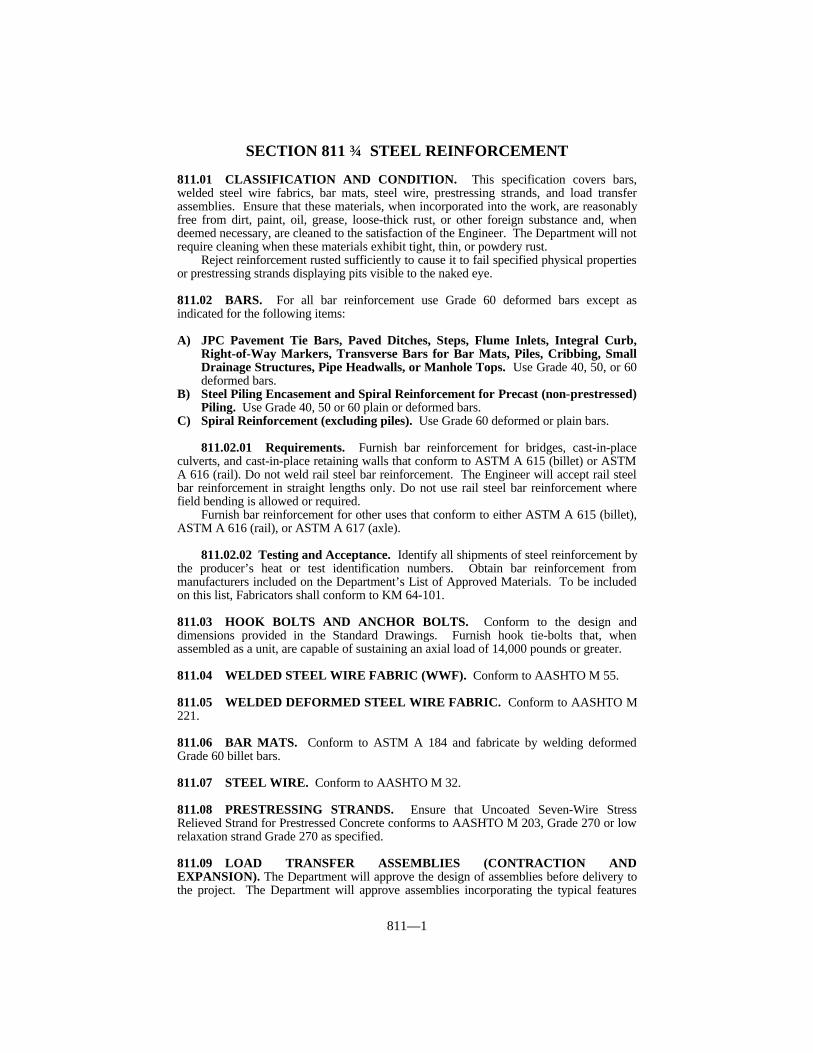
811—1
SECTION 811 STEEL REINFORCEMENT
811.01 CLASSIFICATION AND CONDITION. This specification covers bars,welded steel wire fabrics, bar mats, steel wire, prestressing strands, and load transferassemblies. Ensure that these materials, when incorporated into the work, are reasonablyfree from dirt, paint, oil, grease, loose-thick rust, or other foreign substance and, whendeemed necessary, are cleaned to the satisfaction of the Engineer. The Department will notrequire cleaning when these materials exhibit tight, thin, or powdery rust.
Reject reinforcement rusted sufficiently to cause it to fail specified physical propertiesor prestressing strands displaying pits visible to the naked eye.
811.02 BARS. For all bar reinforcement use Grade 60 deformed bars except asindicated for the following items:
A) JPC Pavement Tie Bars, Paved Ditches, Steps, Flume Inlets, Integral Curb,Right-of-Way Markers, Transverse Bars for Bar Mats, Piles, Cribbing, SmallDrainage Structures, Pipe Headwalls, or Manhole Tops. Use Grade 40, 50, or 60deformed bars.
B) Steel Piling Encasement and Spiral Reinforcement for Precast (non-prestressed)Piling. Use Grade 40, 50 or 60 plain or deformed bars.
C) Spiral Reinforcement (excluding piles). Use Grade 60 deformed or plain bars.
811.02.01 Requirements. Furnish bar reinforcement for bridges, cast-in-placeculverts, and cast-in-place retaining walls that conform to ASTM A 615 (billet) or ASTMA 616 (rail). Do not weld rail steel bar reinforcement. The Engineer will accept rail steelbar reinforcement in straight lengths only. Do not use rail steel bar reinforcement wherefield bending is allowed or required.
Furnish bar reinforcement for other uses that conform to either ASTM A 615 (billet),ASTM A 616 (rail), or ASTM A 617 (axle).
811.02.02 Testing and Acceptance. Identify all shipments of steel reinforcement bythe producer’s heat or test identification numbers. Obtain bar reinforcement frommanufacturers included on the Department’s List of Approved Materials. To be includedon this list, Fabricators shall conform to KM 64-101.
811.03 HOOK BOLTS AND ANCHOR BOLTS. Conform to the design anddimensions provided in the Standard Drawings. Furnish hook tie-bolts that, whenassembled as a unit, are capable of sustaining an axial load of 14,000 pounds or greater.
811.04 WELDED STEEL WIRE FABRIC (WWF). Conform to AASHTO M 55.
811.05 WELDED DEFORMED STEEL WIRE FABRIC. Conform to AASHTO M221.
811.06 BAR MATS. Conform to ASTM A 184 and fabricate by welding deformedGrade 60 billet bars.
811.07 STEEL WIRE. Conform to AASHTO M 32.
811.08 PRESTRESSING STRANDS. Ensure that Uncoated Seven-Wire StressRelieved Strand for Prestressed Concrete conforms to AASHTO M 203, Grade 270 or lowrelaxation strand Grade 270 as specified.
811.09 LOAD TRANSFER ASSEMBLIES (CONTRACTION ANDEXPANSION). The Department will approve the design of assemblies before delivery tothe project. The Department will approve assemblies incorporating the typical features

811—2
depicted by the Standard Drawings. The Department will reject assemblies at any timethat deviate from previously approved designs and manufacturing procedures. Shopfabricate all assemblies.
Where chair bars fit over ends of dowel bars, form them to obtain a snug fit over theend of the dowel bar not welded to the chair bar.
Control welding to prevent a significant reduction in the areas of the dowel bars or thewires. Modify the load-transfer assemblies furnished for slip form construction to allowfor approximately 4 inches of clearance between the assemblies and the slip forms.Accomplish this by welding the outer leg of the chair at an angle of approximately 90degrees with the upper and lower spacer bars.
811.09.01 Chair, Spacer, Aligning Bars, and Upper Tie Bars. Furnish steel forthese items that conforms to AASHTO M 32.
811.09.02 Dowel Bars. Furnish dowel bars that are plain round bars conforming toASTM A 615, A 616, or A 617 with respect to mechanical properties only. Provide eitherGrade 40, 50 or 60 steel. Saw cut the free ends of the dowels and ensure that they are freeof burrs or projections. Coat dowel bars according to AASHTO M 254 with the followingexceptions for Type B coatings:
1) ensure that the thickness is 12 ± 3 mils,2) subject the coated dowel bars to a bend test (KM 64-102),3) use a bond breaker from the Department’s List of Approved Materials for load
transfer assemblies,4) the maximum pull-out load shall not exceed 2,500 pounds,
Use any Type B Coatings that are on the Department’s List of Approved Materials forepoxy coating materials, and apply them (except for thickness) according to Subsections811.10.03 and 811.10.04.
The Department will inspect and accept dowel bars with Type B coatings as specifiedin Subsection 811.10.06. Obtain a Certificate of Compliance as specified in Subsection811.10.07.
811.09.03 Dowel Bar Sleeves. Furnish a sleeve for each dowel bar used withexpansion joints. Place these sleeves on alternate and opposite ends of the dowels. Furnish sleeves manufactured from sheet metal or metal tubing having a minimumthickness of .010 inch, 32 gage. Ensure that they are of such length as to cover no lessthan 2 inches nor more than 3 inches of the dowel, have a closed end, fit the dowel barsnugly, and are of such design as to provide an unobstructed expansion space of no lessthan one inch to allow movement of the dowel bar.
811.09.04 Fabrication Tolerance. Ensure that the longitudinal alignment of dowelbars in load transfer assemblies is within 1/4 inch in 18 inches of the specified alignment.
When checked along the total length of the dowels, allow the deviation to be 0 ± 1/4inch for assemblies on a zero degree skew, and 3 ± 1/4 inch for assemblies on a 9.5 degreeskew.
811.10 EPOXY COATED STEEL REINFORCEMENT.
811.10.01 Uncoated Bars. Ensure that the deformed steel bars conform to theapplicable requirements of Subsections 811.01 and 811.02. In addition, blast clean allsurfaces of the steel bars to a near-white surface finish according to SSPC-SP 10. Blastclean to produce a surface having a profile no greater than 3 mils. Immediately beforeapplication of the coating, ensure that the blast cleaned surface corresponds with eitherpictorial standard A SP 10, B SP 10, or C SP 10 of SSPC-Vis 1, and the surfaces are freeof all dust and grit.

811—3
811.10.02 Epoxy Coating Material. Select the epoxy coating material forreinforcing steel from the Department’s List of Approved Materials. Ensure that thecoating material conforms to the prequalification requirements of ASTM D 3963 Annex. Submit documentation in the form of test results from a private testing laboratory verifyingthat the coating material conforms to ASTM D 3963 to the Division of Materials to gainapproved list status.
Select and furnish the powdered epoxy resin of the same material and quality as theresin which has been previously submitted for prequalification. Ensure that the resinmanufacturer annually furnishes a written certification to the Division of Materials thatattesting to the sameness of the powdered epoxy resin.
Obtain the approval of the Engineer for epoxy material for touch-up and repair work. Ensure that the epoxy material furnished by the epoxy manufacturer is compatible with thecoating material and inert in concrete, and is suitable for use in the field.
811.10.03 Application of Epoxy Coating Material. Notify the Director of theDivision of Materials at least 2 weeks before performing blast cleaning and applying of theepoxy coating, so the Department can inspect the work. Apply the powdered epoxy resinto the blast cleaned steel bars within 8 hours after blast cleaning and before any visiblerusting of the near-white surfaces appears. Apply the resin as an electrostatically chargeddry powder sprayed onto the grounded steel bars by electrostatic sprays. Ensure that thesteel bars are at the temperature recommended by the powdered epoxy resin manufacturerat the time of the application of the coating.
After coating the bars, give them the thermal treatment recommended by themanufacturer of the powdered epoxy resin to provide fully cured coating on the bars. Touch up all uncoated areas of electrical contact points as directed.
Ensure that the epoxy coating applied to the bars is uniform and smooth with 90percent of the film thickness measurements falling between 7 and 12 mils after curing,when checked according to KM 64-102.
The Department will reject the coated bars for either an insufficient or excessive filmthickness or a partially cured coating.
811.10.04 Properties of the Coated Bars. Ensure that the coated bars, after curing,display a continuous, flexible, and abrasion resistant coating as determined by thefollowing.
A) Continuity of Coating. After curing, check all bars visually for defects in thecoating such as holes, voids, delaminations, contamination, and damaged areas. In addition, check for “holidays” (pinholes not visually discernible) according toKM 64-102. When any bar has more than 2 defects or “holidays” per linear footor a total defective area exceeding 0.25 percent of the surface area per linear foot,repair the defects or “holidays” with the touch-up material. When any bar hasmore than 5 defects or “holidays” per linear foot or a total defective areaexceeding 0.5 percent of the surface area per linear foot, the Department willreject the bar.
B) Flexibility of Coating. The Department will evaluate the flexibility of thecoating by bending tests according to KM 64-102. Ensure that the coated barsare capable of being bent 120 degrees (after rebound) over a mandrel, withoutany visible evidence of cracking the coating.
C) Recleaning. Do not remove the coating from rejected bars for the purpose ofrecoating by any process involving temperatures higher than 500 °F.
D) Color of Coating. For all epoxy coatings use a light color that will provide adistinct contrast with the color of cleaned steel, and the color of rusted steel.
811.10.05 Fabrication of Coated Bars. Fabricate the steel bars into the shapes andlengths specified on the bridge plans either before or after coating. When performingfabrication after coating the bars, repair any damage to the coating. Repair the coating onstraight portions of the bars when damaged or bare areas exceed 0.25 percent of the coated

811—4
area per linear foot or when individual damaged areas are in the order of 0.063 squareinch, 1/4 inch by 1/4 inch or larger. When repairing coating, clean and repair all damagedand bare areas on the straight portion of the bar. When the amount of repair in the straightportion of a bar exceeds 2 percent of the surface area per linear foot the Department willreject the bar.
Repair coating within each bent area of the bar when bond loss and damage exceed0.25 percent of the surface area within each bent area or when individual damaged areasare in the order of 0.063 square inch, 1/4 inch by 1/4 inch or larger. When repairingcoating, clean and repair all damage within each bent area. When the amount of repair ina particular bent portion of a bar exceeds 2 percent of the surface area, the Department willreject the bar. It is not necessary to repair hairline cracks that do not have bond loss orother minor damage on fabrication bends.
Do not allow the amount of touch-up area for repair of defects and necessary overlapto exceed 5 percent of the surface area of the bar per meter for straight bars.
Do not allow the amount of touch-up area for repair of defects and necessary overlapto exceed 10 percent of the surface area of the bar per linear foot for bent portions of bars.
The Department will approve of all cleaning and repair methods and materials. Coatthe ends of the coated bars cut during fabrication with the epoxy used for repairs. Repairthe damaged areas and the coating of the ends of cut bars within 24 hours and before anyvisible rusting appears.
Obtain the Department’s approval for any additional requested splices toaccommodate lengths suitable for coating. Make requested additional splices at noadditional expense to the Department.
Coat all areas receiving touch-up material, including ends with a minimum thicknessof 5 mils. The Department will allow a maximum thickness of 16 mils in repair of overlapareas.
Extend touch-up material, applied to sheared or sawn bar ends to coat the resultingdamaged area, up to a maximum of 7 inches from the end of the bar. When the sheared orsawn surface conforms to the specifications after touch-up, the Department will not countthe bar end and first 7 inches from the bar end in determining the percent of repair area.
811.10.06 Inspection and Acceptance. Before subjecting them to blast cleaningand coating with the powdered epoxy resin, confirm that uncoated steel bars are from amanufacturer on the Department’s List of Approved Materials for Reinforcing SteelManufacturers. The Department may inspect and test all materials at the coating plant,and after delivery to the project.
Use an epoxy coater to apply the coating that is on the Department’s List of ApprovedMaterials. To be approved, epoxy coaters must conform to KM 64-101 and KM 64-102.
If the Department’s inspection or testing indicates that material furnished to aDepartment project materially differs from the specification requirements, the Departmentwill review and reconsider the approval of the epoxy coater’s quality control program.
811.10.07 Documentation. Ensure that each shipment of epoxy coated steelreinforcement is accompanied by documentation prepared by the epoxy coater according toKM 64-101.
811.11 ACCEPTANCE PROCEDURES FOR NON-SPECIFICATION REIN-FORCING STEEL. Ensure that all reinforcing steel conforms to the requirements of thissection. However, when non-specification reinforcing steel is inadvertently incorporatedinto the work before completion of testing, the Department may accept the material with areduction in pay, provided the failure is marginal and will not cause poor performance. When the failure is excessive, then remove the reinforcing steel, and replace it unless theEngineer determines that the reinforcing steel can remain in place with a 100 percentreduction rate. The Department will apply the largest payment reduction when thematerial fails to meet more than one specification requirement. The Department willcalculate the payment reduction on the invoice cost of the material delivered at the projectsite. The Department will reject reinforcing steel that fails and has not been incorporatedinto the work.

811—5
YIELD STRENGTH% of Requirement 97% - 100% or more 91% - 96% 86% - 90% 85% or less
Reduction Rate 0% 20% 50% (1)
TENSILE STRENGTH% of Requirement 97% - 100% or more 91% - 96% 86% - 90% 85% or less
Reduction Rate 0% 20% 50% (1)
ELONGATION% of Requirement 97% - 100% or more 91% - 96% 86% - 90% 85% or less
Reduction Rate 0% 20% 50% (1)
WEIGHT PER FOOT% of Requirement 94% - 100% or more 89% - 93% 86% - 88% 85% or less
Reduction Rate 0% 20% 50% (1)
EPOXY COATING THICKNESSThickness (mils) 7 - 13 14 - 15 0 – 6
Over 16Reduction Rate 0% 25% (1)
(1) Remove and replace the reinforcing steel unless the Engineer determines that thesteel can remain in place at a 100% reduction rate.

812—1
SECTION 812 STRUCTURAL STEELS
812.01 STRUCTURAL STEEL SHAPES, PLATES, BARS, AND FASTENERS.Conform to Charpy V-notch toughness requirements for structural steel for load carryingmembers in bridges when specified in the Plans.
812.01.01 Structural Steel, All Types. Conform to AASHTO M 270 (ASTM A709), Grades 36, 50 50W, 70W, HPS70W, 100 and 100W. When the supplementaryrequirement of this specification are specified, they exceed the requirements of ASTM A36, A 514, A 572, A 588, and ASTM A 852.
A) Structural Steel. Conform to AASHTO M 270 Grade 36, ASTM A 709 Grade36, or ASTM A 36.
B) High-Strength Low-Alloy Columbium-Vanadium Steels of StructuralQuality. Conform to AASHTO M 270 Grade 50, or ASTM A 709 Grade 50, orASTM A 572.
C) High-Strength Low-Alloy Structural Steel with 345 MPa Minimum YieldPoint to 4 Inches Thick. Conform to AASHTO M 270 Grade 50W, ASTM M270 Grade 50W, or ASTM A 588.
D) Quenched and Tempered Low-Alloy Structural Steel Plate with 485 MPaMinimum Yield Strength to 4 Inches Thick. Conform to AASHTO M 270Grade 70W, ASTM A 709 Grade 70W, or ASTM A 852.
E) High-Yield-Strength, Quenched and Tempered Alloy Steel Plate, Suitablefor Welding. Conform to AASHTO M 270 Grade 100/100W, ASTM A 709Grade 100/100W, or ASTM A 514.
F) High-Strength Low-Alloy, Quenched and Tempered Structural Steel Plate. Conform to ASTM A 709 Grade HPS70W.
812.01.02 Hot-Rolled Carbon Steel Sheets and Strip of Structural Quality,Grade 33 (Corrugated Steel Plank for Bridge Floors). Conform to ASTM A 570.
812.01.03 Cold Rolled Carbon Steel Sheet of Structural Quality, Grade “D” (40ksi) (Corrugated Steel Plank for Bridge Floors). Conform to ASTM A 611.
812.01.04 Steel Sheet Piling. Conform to AASHTO M 202 (ASTM A 328).
812.01.05 Frames and Grates (for Catch Basins, Inlets, Outlets, and Manholes). Use steel in these items that conforms to the following properties:
Yield Strength 36 ksi. minimumTensile Strength 58 ksi mimimumElongation in 2-inch specimen 21 percent minimum
The Department will accept steel for frames and grates according to the Manual ofField Sampling and Testing Practices.

813—1
SECTION 813 MISCELLANEOUS METALS
813.01 PINS AND ROLLERS. Use steel specified in the AASHTO StandardSpecifications for Highway Bridges conforming to AASHTO M 169 (ASTM A 108) orAASHTO M 102 (ASTM A 668).
813.02 STEEL CASTING. Conform to AASHTO M 103, Grade 70-36 (ASTM A 27).
813.03 EXPANDING STEEL MANHOLE RISERS. Use an approved type thatexpands to fit tightly and rigidly within the existing frame.
813.04 GRAY IRON CASTINGS. Conform to AASHTO M 105, Class 30-B.
813.05 MALLEABLE CASTINGS. Conform to ASTM A 47. Use the gradespecified.
813.06 CASTINGS FOR RIGHT-OF-WAY MARKERS. Provide aluminum alloyconforming to ASTM B 26, Alloy 319.1.
813.07 LEAD PLATES. Manufacture plates from lead conforming to ASTM B 29.
813.08 ALUMINUM.
813.08.01 Cast Aluminum Sand Castings. Conform to ASTM B 26, Alloy356.0-T6.
813.08.02 Aluminum Alloy Permanent Mold Castings. Conform to ASTM B 108.
813.08.03 Aluminum Alloy Sheet and Plate. Conform to ASTM B 209.
813.08.04 Aluminum Alloy Extruded Bars, Rods, Shapes and Tubes. Conformto ASTM B 221, Alloy 6061-T 6511 or Alloy 6063-T 6.
813.08.05 Aluminum Alloy Rolled or Extruded Shapes. Conform to ASTM B308, Alloy 6061-T6.
813.08.06 Aluminum Alloy Seamless Pipe. Conform to ASTM B 241, Alloy6061-T 6 and 6063-T 6.
813.08.07 Aluminum and Aluminum Alloy Bars, Rods, and Wire Bolts. Conform to ASTM F 468, Alloy 2024-T 4. Give finished bolts a minimum anodic coatingof 0.0002 inch.
813.08.08 Aluminum Nuts. Conform to ASTM F 467, Alloy 6061-T6 or 6062-T 9. Give finished nuts a minimum anodic coating of 0.0002 inch.
813.08.09 Welding Rods. Conform to AWS A5.10.
813.09 STEEL BOLTS, NUTS, AND WASHERS.
813.09.01 Carbon Steel Bolts and Nuts. Conform to ASTM A 307. Nuts conformto AASHTO M 291.
813.09.02 High-Strength Steel Bolts, Nuts, and Washers. Mark all bolts, nuts,and washers according to the appropriate ASTM Specifications. If using galvanized bolts,nuts, or washers, measure the thickness of the zinc coating. Take measurements on thewrench flats or top of bolt head.

813—2
Submit mill test reports for all steel used in the manufacture of the bolts, nuts, orwashers to the Department for approval. Include with the mill test reports the place wherethe material was melted and manufactured. The Department will take field samples fortesting to verify compliance with this section.
Ship bolts, nuts, and washers (where required) from each rotational-capacity lot in thesame container. If there is only one production lot number for each size of nut and washer,the Department will allow shipping of the nuts and washers in separate containers. Permanently mark each container with the rotational-capacity lot number to allowidentification at any stage before installation. Supply the appropriate mill test report,manufacturer’s certified test report, or distributor’s certified test report to the Engineerbefore beginning installation.
For bolts, nuts, and washers, conform to the following dimensions:
(1)ANSI Standards B 18.2.1 and B 18.2.2 shall govern tolerance to thesedimensions.
BOLT AND NUT DIMENSIONS (1)
Bolt Dimensions Nut Dimensionsin in
Heavy Hexagon HeavyNominal Structural Bolts Hexagon Nuts
Bolt Width Height Thread Width HeightSize Across Length Acrossin Flats FlatsD F H T W H
1/2 7/8 5/16 1 7/8 31/645/8 1 1/16 25/64 1 1/4 1 1/16 39/643/4 1 1/4 15/32 1 3/8 1 1/4 47/647/8 1 7/16 35/64 1 1/2 1 7/16 55/641 1 5/8 39/64 1 3/4 1 5/8 63/64
1 1/8 1 13/16 11/16 2 1 13/16 1 7/641 1/4 2 25/32 2 2 1 7/321 3/8 2 3/16 27/32 2 1/4 2 3/16 1 11/321 1/2 2 3/8 15/16 2 1/4 2 3/8 1 15/32

813—3
(1)ANSI Standard B 18.22.1 Type A washer tolerances apply to the nominal dimensionsfor outside diameter and hole diameter.
(2)May be exceeded by 1/4 inch.(3)3/16 inch nominal.
A) Bolts. Conform to AASHTO M 164 (ASTM A 325). Do not use boltsconforming to AASHTO M 253 (ASTM A 490). Hardness for bolt diameters1/2 to 1 inch inclusive are as noted below:
Perform proof load testing according to ASTM F 606 Method 1 at theminimum frequency specified in ASTM A 325.
Perform wedge testing on full size bolts according to ASTM F 606paragraph 3.5 at the minimum frequency specified in ASTM A 325. If bolts areto be galvanized, perform tests after galvanizing.
Plain bolts must be oily to touch when delivered and installed.B) Nuts. Conform to AASHTO M 292 (ASTM A 194) as applicable or AASHTO
M 291. If nuts are to be galvanized (hot dip or mechanically galvanized), useheat treated Grade 2H, DH, or DH3.
For plain (ungalvanized) nuts, use Grades 2, C, D, or C3 with a minimumRockwell hardness of 89 HRB (or Brinell Hardness 180 HB), or heat treatedGrades 2H, DH, DH3.
For nuts that are to be galvanized, overtap the nuts the minimum amountrequired for proper assembly allowing the nut to assemble freely on the bolt inthe coated condition. Overtap the nuts according to the mechanical requirementsof AASHTO M 291 and the rotational-capacity test requirements of this section.
Lubricate galvanized nuts with a lubricant containing a dye that contrasts
WASHER DIMENSIONS IN MILLIMETERS(1)
Square of Rectangular BeveledCircular Washers Washers for American Standard
Beams and ChannelsNominal Nominal Minimum Slope or
Bolt Outside Diameter Thickness Side Mean Taper inSize Diameter(2) of Hole Min. Max. Dimension Thickness Thickness1/2 1 1/16 17/32 0.097 0.177 1 3/4 5/16 1:65/8 1 5/16 21/32 0.122 0.177 1 3/4 5/16 1:63/4 1 15/32 13/16 0.122 0.177 1 3/4 5/16 1:67/8 1 3/4 15/16 0.136 0.177 1 3/4 5/16 1:61 2 1 1/16 0.136 0.177 1 3/4 5/16 1:6
1 1/8 2 1/4 1 1/4 0.136 0.177 2 1/4 5/16 1:61 1/4 2 1/2 1 3/8 0.136 0.177 2 1/4 5/16 1:61 3/8 2 3/4 1 1/2 0.136 0.177 2 1/4 5/16 1:61 1/2 3 1 5/8 0.136 0.177 2 1/4 5/16 1:6
1 3/4 3 3/8 1 7/8 0.178(3) 0.28 (3) 2 3 3/4 2 1/8 0.178 0.28
HARDNESS NUMBER
Bolt Size Brinell Rockwell C
(in) Min. Max. Min. Max.1/2 - 1 253 319 25 34

813—4
with the color of the galvanizing.Perform proof load testing according to ASTM F 606, paragraph 4.2 at the
minimum frequency specified in AASHTO M 291 or AASHTO M 292 (ASTMA 194). If nuts are to be galvanized, perform tests after galvanizing, overtapping,and lubricating.
C) Washers. Conform to AASHTO M 293. If supplying galvanized washers,perform hardness testing after galvanizing. Remove coating before takinghardness measurements.
D) Rotational-Capacity Test. Perform rotational-capacity tests on all black orgalvanized (after galvanizing) bolt, nut, and washer assemblies by themanufacturer or distributor before shipping. Perform additional rotational-capacity tests on each lot at job sit. Use washers as part of the test even thoughthey may not be required as part of the installation procedure. Perform thefollowing:
1) Except as modified herein, perform rotational-capacity testing according toAASHTO M 164.
2) Test each combination of bolt production lot, nut lot, and washer lot,shipped as a rotational-capacity lot, as an assembly. Where washers are notrequired by the installation procedures, the Department will not require lotidentification for them.
3) Assign a rotational-capacity lot number to each combination of lots tested.4) Test at least 2 assemblies per rotational-capacity lot.5) Assemble the bolt, nut and washer assembly in a Skidmore-Wilhelm
Calibrator or an acceptable equivalent device (Note this requirementsupersedes the ASTM A 325 requirement that the test be performed in asteel joint). For bolts too short to be assembled in the Skidmore-WilhelmCalibrator, test them according to 9) below.
6) Provide the minimum rotation, from a snug tight condition (10 percent of thespecified proof load), as follows:
300 degrees (0.83 turn) for bolt lengths ≤ 4 diameters360 degrees (1 turn) for bolt lengths > 4 diameters and ≤ 8 diameters480 degrees (1.33 turns) for bolt lengths > 8 diameters
7) Ensure that the tension reached at the above rotation is ≥ 1.15 times therequired installation tension. The installation tension and the tension for theturn test are as noted below:
8) After exceeding the required installation tension listed above, take and
TENSION
Diameter Req. Installation Turn Test Tension(inches) Tension (kips) (kips)
1/2 12 145/8 19 223/4 28 327/8 39 451 51 59
1 1/8 56 641 1/4 71 821 3/8 85 981 1/2 103 118

813—5
record one reading of tension and torque. Ensure that the torque valueconforms to the following:Torque ≤ 0.25 PD
Where: Torque = measured torque (foot-pounds)P = measured bolt tension (pounds)D = bolt diameter (feet)
9) Test bolts too short for assembly in a Skidmore-Wilhelm Calibrator in asteel joint. Disregard the tension requirement of 7) above. For themaximum torque requirement of 8) above, use a value of P equal to the turntest tension shown in the table in 7) above.
The Department will not require an inspection agency present duringtesting; however, the manufacturer or distributor performing the tests shallcertify that the results recorded are accurate. The Engineer reserves the rightto witness testing on request.
Ensure that the lot number appearing on the shipping package for bolts,washers, and nuts corresponds to the lot number identified on thedistributor’s and manufacturer’s certification.
Provide the Engineer with the certified test report from the manufactureror distributor performing the rotational-capacity test. Include the followinginformation:
a) The lot number of each of the items tested.b) The rotational-capacity lot number.c) A statement that the items conform to this section and the Contract.d) The results of the tests.e) The location and date of the tests.f) The location where the bolt assembly components were manufactured.
813.09.03 Corrosion-Resisting Steel Bolts and Set Screws. Fabricate bolts andscrews from bars conforming to ASTM A 276. Use Types 302 or 304 for steel machinebolts to attach aluminum posts to concrete and for steel set screws for aluminum railings.
813.09.04 Stainless Steel Hardware, Bolts, Nuts, and Washers. Conform toASTM A 320.
813.09.05 Cadmium Coatings for Steel Anchor Bolts, Nuts, and Washers. Conform to ASTM B 766, Class 12, Type II.
813.10 WELDING MATERIAL, PROCEDURES, AND INSPECTION. Forbridges comply with the ANSI/AASHTO/AWS D1.5 Bridge Welding Code withmodifications and additions as specified in the Plans.
For other steel structures comply with the AWS Structural Welding Code D1.1 withmodifications and additions as specified in the Plans. For aluminum structures complywith the AWS Structural Welding Code-Aluminum D1.2.
813.11 STUD SHEAR CONNECTORS. Conform to AASHTO M 169 (ASTM A 108,Grade 1015).
813.12 HANDRAIL.
813.12.01 Type B. Fabricate the channel, picket, and posts using hot rolled steelconforming to AISI M 1020; ASTM A 519, Grade 1020; ASTM A 575, Grade M 1020; orASTM A 659, Grade 1020. For the lambs tongue, use either a gray iron casting or acommercial grade steel. After fabrication and cleaning, paint the handrail with 2 coats ofcommercial grade primer paint and one coat of commercial grade black enamel. Repaint

813—6
damaged areas as directed.
813.12.02 Type C. Furnish aluminum posts and rails conforming to ASTM B 221,alloy 6063, temper T52. Provide rails with a polished finish and posts and fittings with asatin finish. Use aluminum alloy fittings for handrails as recommended by the handrailmanufacturer.
813.13 MATTRESSES AND GABIONS. Conform to ASTM A 975, Style 1 orASTM A 974, Style 1 or 2. Use wire with a minimum elongation of 10 percent of thelength of the wire when tested according to ASTM A 370 without reducing the diameter ortensile strength of the wire.
Supply lacing wire in sufficient quantity to ensure that all required tying, connecting,and lacing can be performed. For Department direct purchases, supply an amount oflacing wire equal to or greater than 8 percent of the weight of the units.
Fabricate the mattress units to the dimensions required by the Contract. TheDepartment will accept mattresses with dimensions within ± 3 percent of the orderedwidth.
813.13.01 Mattress Units. As an alternate to lacing wire, the Engineer will allowmattress unit fasteners, from the Department’s List of Approved Materials, that conform tomattress unit manufacturer’s recommended assembly and connection instructions.
Subdivide the mattress units into compartments a maximum of 3 feet in lengthextending over the full width of the mattress unit by inserting diaphragms made of thesame mesh as the rest of the mattress unit. Secure the diaphragms in position on thebottom with a continuous spiral wire at the factory so no additional tying at this joint isnecessary.
813.13.02 Gabion Baskets. As an alternate to lacing wire, the Engineer will allowgabion unit fasteners, from the Department’s List of Approved Materials, that conform tomattress unit manufacturer’s recommended assembly and connection instructions.
Supply diaphragms of the same material composition as the gabion to form individualcells of equal length and width when the gabion length exceeds its width.
813.13.03 Acceptance. The Department will test each shipment for wire size andzinc coating, and will perform any other Engineer ordered tests. The Department willaccept shipments based on laboratory testing and the Engineer’s visual inspection.

814—1
SECTION 814 GUARDRAIL SYSTEMS
814.01 DESCRIPTION. This section covers material requirements for corrugatedsheet steel beams and accessories for guardrail, terminal sections, guardrail posts, offsetblocks, end treatments, and timber guard posts.
814.02 BEAMS AND ACCESSORIES. Conform to AASHTO M 180. Hardware forType I, II, or III beams may be either hot-dip galvanized, electrogalvanized, ormechanically galvanized. Galvanize according to AASHTO M 232. The Engineer willreject beams with zinc oxide (white rust) in amounts deemed objectionable. Furnish TypeII beams of either Class A, 0.105 inch thick or Class B, 0.135 inch thick as specified in theContract.
814.03 TERMINAL SECTIONS. Conform to AASHTO M 180 and the details shownon the Standard Drawings. Galvanize sections after fabrication. Furnish Type 2 sectionsof either Class A, 0.105 inch thick or Class B, 0.135 inch thick as specified in theContract.
814.04 GUARDRAIL POSTS. Provide either steel or timber, and use the same typethroughout the Project.
814.04.01 Steel Guardrail Posts. Fabricate from steel conforming to ASTM A 36for the wide flange shapes. Punch or drill holes for connector bolts before galvanizing. Galvanize all posts according to AASHTO M 111.
814.04.02 Timber Guardrail Posts. Furnish either square sawn or round timberguardrail posts. Conform to the nominal dimensions shown on the Standard Drawings. The Engineer will allow a minus 2-inch tolerance from the specified nominal length. Sawthe butts of all posts square, and finish the tips as specified in the Contract.
Bore bolt holes to a driving fit for the bolts. Frame, bore, and trim, as much as ispractical, before giving the posts a preservative treatment. When it is necessary to bore orcut the posts after treatment, or when any treated surface has been badly scarred, treat thecut or scarred surface according to AWPA M4.
Treat the posts with preservative according to AWPA C 14 as applicable for guardrailposts. Use only one type throughout the project unless otherwise approved by theEngineer.
Use any of the species of wood for round guardrail posts covered under AWPA C 5. Use any of the softwood species for square sawed posts covered under AWPA C 2. Whenfurnishing oak posts, treat with creosote or creosote solution according to AWPA C 2 for“Above Ground, Soil or Fresh Water Exposure.”
See Subsection 818.01 for inspection, testing and acceptance procedures for TimberGuardrail Posts.
A) Square Sawed Posts. Ensure the posts, in the direction parallel to the axis of thebolt holes, do not exceed the dimensions specified in the Contract by more than1/4 inch.
Use posts that have straight grain, and that have a slope of the grain notdeviating more than one inch in 12 inches from being parallel to any face whenmeasured over the middle one-half of the length. The Engineer will not acceptposts having a crook exceeding 1/2 inch in 10 feet. Limit wane to one end of thepost only, and do not allow it to extend more than 10 feet from that end. Do notreduce the flat width of any face by more than 25 percent at the point of mostwane. Do not use wood with ant tunnels, woodpecker holes, plugged holes, orany large unsightly gaps. The Department will allow wood with grub and wormholes less than 1/2 inch in average diameter, provided that the sum of thediameters of all holes in any 12 inches of post length does not exceed 1/4 the

814—2
nominal width of the face. Do not use posts showing signs of powder post beetleinfestation. The Engineer will not limit the use of posts that have grub holesappearing entirely on the surface of the post and that do not penetrate to morethan 1/2 inch in maximum depth.
Do not use posts with knots greater than 3/8 the nominal width of the face,measured by the smallest diameter. Do not allow the sum of the diameters of allknots in any 6 inches of post length to exceed 3/4 the nominal width of the face. Do not allow the sum of the diameter of all knots appearing within the middlehalf of the length of any face to be greater than 4 times the size of the largest knotallowed in that face. The Department will allow posts with unsound knots nolarger than half the maximum allowable size for sound knots and no more than 11/2 inches in depth, provided that the surrounding wood is not affected by thedecay. Do not use posts that have clusters of knots where the maximumdistortion of the grain around the cluster exceeds the maximum allowable size forone knot.
Entirely confine shakes within the ends of the post, without extending to anyface. Measure the shake as the sum of the 2 adjoining sides of the smallestrectangle that will completely enclose the shake. Measure the sides of therectangle parallel to the faces of the post. Do not allow shakes to occur in morethan one annual ring or to extend to more than 3/4 of the circumference of theannual ring in boxed heart. Do not allow total shake measurement to exceed one-half the width of the face.
Do not use posts with splits greater in length than the width of the face. Donot use posts with a check or series of contiguous checks having a width of 8 mmor greater at the surface and more than 3 inches in depth at any point andextending more than 3/4 of the length of the post from one end. The Engineerwill determine the depth of checks by the penetration of a probe 1/64 inch thickand 1/4 inch wide. The Engineer will consider the extent of a check or series ofcontiguous checks to end at the last point where the opening does not exceed 1/8inch in width and is no more than 3/4 inch in depth.
Do not use any post having a shake that does not exceed the maximumlimits for shakes as specified herein, but contains a check which penetrates to theannual ring in which the shake occurs.
B) Round Posts. Peel all posts for their full length, and remove all outer and innerbark. Shave all knots and projections smooth and flush with the surface of thesurrounding wood.
Ensure that the posts are a constant diameter not less than 1/4 inch under thenominal diameter.
Do not use posts that have short or reverse bends, one way sweepsexceeding one inch, and winding twists that are unsightly and exaggerated. TheEngineer will not allow more than 10 percent of the number of pieces of anyshipment to contain the maximum sweep.
Do not use posts with unsound, loose or hollow knots. The Department willallow use posts that have sound knots when the diameter of any one knot orwhen the combined diameters of 2 or more knots occurring in the same crosssection are no greater than 1/3 of the diameter of the post at that cross section.
Ensure that posts are close grained and do not show spiral grain exceeding1/8 turn in 5 feet.
Do not use posts with seasoning checks that penetrate the interior of the postto a depth greater than 1/3 of the diameter at any point, or which measure morethan 1/4 inch in width at any point.
Do not use posts that have ring shakes, sap rot, bird pecks, insect holes,pitch pockets, or pitch streaks, and other defects that will impair the strength ofthe post, or give it an unsightly appearance.
814.05 OFFSET BLOCKS. Use the size, and when specified, the type the Contractspecifies.

814—3
814.05.01 Wood. Conform to 814.04 for material properties.
814.05.02 Composite Plastic. Use blocks that are uniform in compositionthroughout the product and consist of at least 70 percent plastic by weight. Rubber is anacceptable alternative to plastic in their composition. Use sufficient additives to inhibitphoto degradation. The Department will consider 2 percent carbon black to be aminimum. Ensure the blocks conform to the National Cooperative Highway ResearchProgram (NCHRP) 350 Test Level 3 requirements.
Submit a written manufacturer’s certification to the Engineer stating the materialcomposition conforms to this subsection and is the same that was tested and approvedunder NCHRP 350.
814.06 MATERIALS FOR END TREATMENTS. Conform to Subsections 814.02through 814.05 for common components, and, except where otherwise provided, ensurethey are of the same class and type as required for the guardrail to which they are attached. Galvanize all non-corrosion-resistant metals used in end treatments according toAASHTO M 111 or AASHTO M 232 as applicable. For other materials, comply with thefollowing requirements:
A) Anchorage Systems. Furnish anchorage systems that have a minimum breakingstrength of 40,000 pounds. The anchorage system may employ either a cableassembly or continuous steel rod or other system of equal or greater strength whenapproved. For cable assemblies, use cable that is 3/4-inch (6 by 19) wire ropeconforming to AASHTO M 30, Class C. Provide swage fittings as required by theStandard Drawings and include studs as required. Ensure that eye bolts conform toASTM A 489 and are of either Type 1 or Type 2. For wire rope clips use acommercial grade capable of being torqued to a minimum of 130 foot-pounds.
Use commercial grade wire rope thimbles.B) Anchor and Miscellaneous Plates. Fabricate from steel conforming to Subsection
812.01.01.C) Miscellaneous Hardware.
Bolts ASTM A 307Nuts ASTM A 563, Grade A or better
D) Steel Sheet (for rail plates and mounting brackets). Conform to ASTM A 1011,Type SS, Grade 36
E) Tubular Sections (for posts and blocks). Conform to ASTM A 500, Grade B orASTM A 501.
F) Steel Drums. For steel drums conform to Federal Specification PPP-D-729C forType II, straight side, with rolled or expanded hoops, cylindrical drum; double seamedwithout chime reinforcement. Ensure that average diametrical crushing strength perdrum is 6,000 pounds with maximum variation for 10 tests being 400 pounds.Galvanize steel drums on all surfaces according to AASHTO M 111.
G) Concrete. Conform to Section 601, Class A.H) Welded Wire Fabric. Use welded wire fabric for concrete reinforcement that is W3
by W3, 6 by 6-inch conforming to Subsection 811.04. The Department may allowother approved types of steel reinforcement.


815—1
SECTION 815 CAST ALUMINUM BRIDGE RAILING POSTS
815.01 CHEMICAL COMPOSITION. Conform to ASTM B 108, Alloy A 356.0. Contrary to ASTM B 108, heat treat to a T6 temper instead of T61 to produce thefollowing tensile properties:
(1)For the purposes of design in the tension test, ensure that the specimensconform to the minimum yield strength of 18,000 psi (acceptance testing forthis property is not required).
(2)Minimum tensile properties based on separately cast test bars are 32,000 psitensile strength and 10 percent elongation.
(3)Gage length 4 times the diameter of the specimen.
815.02 TEST SPECIMENS. Machine the tension test specimens from integrally casttest coupons extending from one side of the base of the posts sufficiently large enough toobtain an 0.350-inch diameter test specimen as defined in ASTM E 8.
815.03 TESTING. Sample a minimum of one percent of the posts in any lot, but notless than one, for tensile testing. For the purpose of sampling, a lot shall consist of notmore than 1,000 pounds of clean castings when produced from a batch type furnacecharged with one heat of ingot of known analysis or not more than 2,000 pounds of cleancastings when produced from one continuous furnace in not more than 8 consecutivehours.
Determine tensile properties according to ASTM E 8. When the results of any tensiletest do not conform to the requirements prescribed, perform 2 additional tests on the samegroup of castings. The average of the 3 tests must conform to the requirements.
815.04 HEAT TREATMENT. Heat treat the castings to produce material with theutmost uniformity conforming to the properties specified in this section. Perform heattreatment on the whole casting, never on a portion only.
815.05 WORKMANSHIP AND FINISH. Ensure that castings are uniform in qualityand condition, free from cracks, blowholes, porous places, hard spots, shrinkage defects, orother defects that may detrimentally affect the suitability of the castings for their intendeduse. Ensure that the castings are smooth and well cleaned before inspecting.
Produce castings under radiographic control. Radiographically examine castings toestablish proper foundry technique for each mold that will produce castings commerciallyfree from harmful internal defects, and examine production castings to ensure maintenanceof satisfactory quality.
Provide a normal mill finish.
815.06 INSPECTION. The Department may inspect the manufacturer’s work eitherwhere the castings are made or at the point at which they are received.
The Department will either visually inspect the castings or compare the castings by amethod adopted as standard to determine compliance with the requirements of Subsection815.05.
When the Department elects to have inspection made at the manufacturer’s works, themanufacturer shall afford the inspector representing the Department all reasonablefacilities to verify that the material is being furnished according to this section. TheDepartment will conduct all tests and inspection in a manner not interfering unnecessarily
TENSILE PROPERTIES (1)
Properties Minimum TypicalTensile Strength, psi (1) 25,000 30,000Elongation in 4x Diameter, % (2),(3) 6 8

815—2
with the operation of the works.
815.07 INSPECTION REPORTS. When requested by the Department, furnishcertified inspection reports certifying compliance with the requirements of this section.

816—1
SECTION 816 WOVEN-WIRE FENCING MATERIALS
816.01 DESCRIPTION. This section covers the materials for use in construction ofwoven-wire fences.
816.02 GENERAL. Galvanize all ferrous materials used in a complete installation offence, except aluminum coated fabric, aluminum coated posts and braces, or aluminumcoated barbed wire. Galvanize all iron and steel hardware according to AASHTO M 232.Galvanize other components as designated. Where it is not practical to secure a specimenof measurable area or uniform thickness for determining the weight of zinc coating, ensurethat all such galvanizing withstands 4 dips of the Preece Test as set out in ASTM A 239. Ensure that post caps and socket type brace connections are galvanized malleable iron, orother approved type, and designed to exclude moisture from inside posts or rails.
816.03 WOVEN WIRE FABRIC. Ensure that the woven wire fabric is either zinc-coated steel or aluminum-coated steel. Provide the size and style of fabric specified in theContract.
Use zinc-coated steel fabric that conforms to ASTM A 116 and that has a Class 3coating.
Use aluminum-coated steel fabric that conforms to ASTM A 584.
816.04 BARBED WIRE. Use either zinc-coated steel, aluminum-coated steel, oraluminum alloy. Use barbs of 4-point pattern spaced at intervals of 5 inches. The wire forbarbs may be either round or half-round.
816.04.01 Zinc-Coated Steel. Conform to ASTM A 121. Use size 0.099-inchdiameter or heavier with Class 3 coating. The Department will allow high tensile strengthbarbed wire provided it conforms to ASTM A 121, and the following exceptions: (1)nominal diameter of 0.067 inch for the coated line wires and 0.057 inch for the coatedbarbs; (2) minimum weight of zinc coating of 0.75 ounces per square foot for line wiresand 0.70 ounces per square foot for barbs; and (3) minimum tensile strength of 475 poundsfor each individual strand of the line wire.
816.04.02 Aluminum-Coated Steel. Use either Type I or Type II conforming toASTM A 121. Use size 0.099 inch diameter or heavier.
816.04.03 Aluminum Alloy. Use 2 strands of 0.110 inch nominal diameter orheavier wire strands having minimum tensile strength of 42,000 psi, minimum yieldstrength of 35,000 psi and minimum elongation of 10 percent.
816.05 BRACE WIRE. Conform to ASTM A 777-91 except provide a minimumweight of coating of 0.6 ounce per square foot. Use size 0.148-inch nominal diameter orlarger.
816.06 FABRIC TIES. Use either a minimum 0.109-inch nominal diametergalvanized steel conforming to ASTM F 626, except ensure that the minimum weight ofcoating is 0.6 ounces per square foot, or 0.148-inch nominal diameter aluminum alloy.
816.07 FENCE POSTS AND BRACES.
816.07.01 Steel Posts and Braces. Conform to ASTM F 1043, ASTM F 1083, andthe Standard Drawings.
When the Contract specifies a thermoplastic acrylic coating, apply a chromateconversion coating at the manufacturer’s recommended rate. Ensure that the coating isdesigned for pretreatment of galvanized coatings. After pretreating, electrostatically applythe thermoplastic acrylic coating with a minimum dry film thickness of 0.3 mils.

816—2
816.07.02 Wood Posts and Braces. Treat wood fence posts and braces withpreservative and ensure that they are made of timber cut from live, sound, standing trees. See Subsection 818.01 for inspection, testing and acceptance of wood products. Ensurethat round or half-round posts and braces are preservative treated according to and are ofthe species covered by AWPA C 5. Ensure that sawed posts and braces are preservativetreated according to and are of the species covered by AWPA C 2 for “Soil or Fresh WaterExposure”.
Use posts that are round, half-round, or square-sawed.Ensure that wood for fence posts is sound and free from decay, excessive knots,
seasoning checks, and end splits that will affect serviceability. The Department will allowsound knots, provided the width of the knot does not exceed one-third the diameter of around post at the point where it occurs, or one-third the width of any face of a sawed post,or a maximum of 2 1/2 inches. The Department will reject wood with season checks thatpenetrate more than one-third of the diameter of the piece or which have a width of morethan 1/4 inch.
Use round posts and half-round posts that are free of multiple crooks. TheDepartment will allow crooks in one plane only, provided that a straight line between thecenters of the butt and tip does not deviate more than 2 inches from the center of the post atany point. Ensure that crooks in square-sawed posts do not exceed one inch in 5 feet.
Cleanly peel round posts and remove all bark. Strips of inner bark that are less than1/2 inch wide and 3 inches long may remain on the peeled post. Trim all protruding knotsflush with the sides and remove all spurs and splinters. In machine peeling operations,follow the natural taper of round posts. Manufacture half-round posts by sawing in halfthe round posts complying with the above manufacturing methods.
Square cut the ends of all posts unless the Engineer allows driving. When driving isspecified or allowed, point the butt end before receiving preservative treatment. Do notallow the length of the point to exceed 1.5 times the diameter or width of face, asapplicable.
A) Line Posts. Use line posts with a length of 7 feet and a minus one-inchtolerance. Use line posts that are either round, half-round, or square-sawed;however, furnish the same type section for all line posts throughout the project.
Ensure that round posts have a minimum diameter of 4 inches. Ensure thathalf-round posts have a minimum face of 6 inches and a minimum radius of 23/4 inches. Cut square-sawed posts to 4-inch by 4-inch, ± 1/8 inch.
B) End, Corner, Gate, Brace, and Pull Posts. Do not use lengths less than 8 feet.Use either round or square-sawed posts; however, furnish the same type sectionfor all of these types throughout the project. Ensure that round posts have aminimum diameter of 8 inches. Cut square-sawed posts to 8-inch by 8-inch,± 1/8 inch.
C) Braces. Conform to all requirements for line posts, except use braces that areeither round or square-sawed and furnish them in the lengths specified in thePlans.
816.07.03 Untreated Wood Posts. Furnish untreated wood posts of Osage-Orange,Black Locust, Red Cedar, White Oak, or of other approved species, and ensure that postsconform to all applicable requirements of Subsection 816.07.02. Use untreated woodposts only when specified in the Contract.
816.08 GATES. Fabricate gate frames to the size and dimensions specified in theContract. Ensure that pipe used in frames conforms to Subsection 816.07.01. Weld orotherwise construct all joints to form a rigid and water-tight frame.
Furnish all gates complete with approved hinges, latches, and auxiliary braces asrequired.
Fit gate frames with a fabric that conforms to the same requirements as thecorresponding fence.

816—3
The Department may approve the use of gates fabricated of other materials.

817—1
SECTION 817 CHAIN LINK FENCING MATERIALS
817.01 DESCRIPTION. This section covers materials for use in the construction offences of chain link fabric. The Department will allow 3 optional types of fabric; zinc-coated steel, aluminum-coated steel, or aluminum alloy (Type I, II, or III fabric,respectively). Use vinyl coated fabric (Type IV) only when specified in the Contract.
817.02 REQUIREMENTS. Conform to AASHTO M 181 for all materials except steelposts and barbed wire.
817.02.01 Fabric. Use 0.148-inch nominal diameter wire woven in 2-inch mesh. Coat Type I fabric to conform to Class D. Furnish fabric for fences 4 feet and 6 feet highthat has the top selvages knuckled and bottom selvage knuckled or twisted and barbed. Furnish fabric for fences 8 feet high or higher with both top and bottom selvages twistedand barbed.
817.02.02 Barbed Wire. Conform to Subsection 816.04.
817.02.03 Post Caps and Socket Type Brace Connections. Use galvanizedmalleable iron, or other approved type, designed to exclude moisture from inside posts andrails.
817.02.04 Posts, Rails, Gate Frames and Expansion Sleeves. With zinc-coatedsteel fabric or with aluminum-coated steel fabric, use either zinc-coated steel or zinc-acrylic coated steel. With aluminum alloy fabric, use aluminum alloy. Furnish steel poststhat comply with Subsection 816.07.01.
817.02.05 Fabric Ties. Use either a minimum 0.148-inch nominal diameteraluminum alloy or 0.120-inch nominal diameter galvanized steel.
817.02.06 Hog Rings and Tension Wire. With zinc-coated steel fabric or withaluminum-coated steel fabric use zinc-coated steel wire or aluminum-coated steel wire.Ensure that steel ties and wire conform to ASTM F 626, except that the minimum weightof coating is 0.6 ounces per square foot. With aluminum alloy fabric, use aluminum alloywire.
817.02.07 Miscellaneous Fittings and Hardware. With zinc-coated steel fabric orwith aluminum-coated steel fabric use zinc-coated steel. With aluminum alloy fabric, usealuminum alloy.

818—1
SECTION 818 WOOD PRODUCTS
818.01 INSPECTION, TESTING, AND ACCEPTANCE. The Engineer willvisually inspect and approve all treated wood products before use on the project. TheDivision of Materials will grade inspect, sample, and test all treated wood products beforetheir use on the project if the plant producing the wood materials is located within theCommonwealth or a 100-mile driving distance of its borders. When obtaining treatedwood materials from a plant outside this 100-mile distance, have an independent treated-wood testing company approved by the Division of Materials grade inspect, sample, andtest the wood treated material at no expense to the Department. Obtain a report preparedby the independent testing firm that grade inspected, sampled and tested the treated woodmaterial, and submit it to the Division of Materials at least 15 days before using the woodmaterials on the project.
Use only treated wood that has been cut to size before treating. Treat field sawnsurfaces according to AWPA M4.
818.02 BOARDS. Boards are defined as being less than 2-inch in nominal thicknessand one inch or more in width. Only use boards that are one of the available gradesestablished by either the Southern Pine Inspection Bureau (SPIB) or the West CoastLumber Inspection Bureau (WCLIB). The Contract will designate the grade andapplicable inspection bureau.
818.03 DIMENSION LUMBER. Dimension lumber is limited to surfaced softwoodlumber of nominal thickness from 2-inch through 4-inch. Only use dimension lumber forframing members such as joists, planks, rafters, studs, and small timbers.
Use only dimension lumber boards that are one of the available grades established byeither the SPIB or the WCLIB. The Contract will designate the grade and applicableinspection bureau.
818.04 TIMBERS, 5-INCH BY 5-INCH AND LARGER. Use only timbers that areof one of the available grades established by either the SPIB or the WCLIB. The Contractshall designate the dimensions, grade, species, and applicable inspection bureau.
818.05 STRUCTURAL LUMBER. Conform to the AASHTO Standard Specificationsfor Highway Bridges.
818.06 BRIDGE PLANKING AND ROUGH LOCAL HARDWOODS.
818.06.01 Species. Use only bridge planking that is White Oak, Red Oak, orSouthern Yellow Pine.
The term “White Oak” includes White Oak, Chestnut Oak, Post Oak, Burr Oak,Swamp Chestnut Oak, Swamp White Oak, Live Oak, Chinquapin Oak, and other lessknown varieties of oak of this character.
The term “Red Oak” includes Red Oak, Black Oak, Southern Red Oak, Willow Oak,Water Oak, Pin Oak, Cherrybark, or Swamp Red Oak, and other less known varieties ofoak of this character.
Southern Yellow Pine may be any species except Field or Loblolly.
818.06.02 Quality of White Oak or Red Oak. The Engineer will not approve woodfor use that has splits, rot, or unsound knots. Use only pieces that are sawed full tospecified sizes and lengths, with square edges except wane (bark or the lack of wood) asfollows. The Engineer will allow wane on one corner on 30 percent of the pieces in anyshipment, not to exceed 15 percent of the width of the face on which it appears. TheEngineer will allow this grade with sound stains, scattered worm holes or grub holes notmaterially affecting the strength of the piece and sound bird pecks, or their equivalent;sound knots or their equivalent not exceeding in diameter 25 percent the width of the face

818—2
in which they appear. Use only boxed heartcenter wood products. Cut pieces not largeenough to box the heartcenter outside the heart except that sizes 2 to 6 inches in thickness,6 inches wide and wider, may show heart on one face only, in 30 percent of the pieces inany shipment.
818.06.03 Quality of Southern Yellow Pine. Conform to the SPIB grades asfollows:
A) Structural Light Framing (2-inch by 2-inch to 4-inch by 4-inch). Provide No.1 Dense.
B) Structural Joists and Planks (3-inch by 8-inch or 4-inch by 6-inch). ProvideNo. 1 Dense.
C) Stress Rated Timbers (5-inch by 5-inch and larger). Provide No. 1 SR.
818.06.04 Dimensions and Tolerances. Use rough timber that is cut full size asspecified, sawed true with parallel faces. The Engineer will allow no more than 25 percentof a lot or shipment to be scant 1/4 inch in thickness and no more than 10 percent of a lotor shipment may be scant 1/4 inch in width.
Ensure that dressed dimensions for both oak and pine material conform to SouthernPine Inspection Bureau thicknesses and widths for Dimension Lumber.
818.06.05 Rough Local Hardwood. This subsection covers hardwood lumber andtimber that is produced locally. Use only White Oak, Red Oak, or Beech hardwood. Where hardwood material is intended to be used inside, the Department will allow otherspecies of hardwood, that are suitable for the intended use, when such species arespecified.
1) Use only material that is cut from live standing trees and is free from any form ofdecay.
2) The Department does not require seasoned material.3) Cut all pieces to a square edge with no less than 75 percent heart, girth
measurement, for full length of the piece.4) Saw all material to the full nominal dimensions.5) Ensure that all knots are tight and sound. Do not allow any material with a knot
of greater diameter than half of the width of the face on which it occurs. Allowonly one maximum knot, or small knots aggregating in diameter of onemaximum knot, in each one-foot length of timber.
6) Ensure that all material is reasonably free from crook and warp.7) Do not allow any piece that has a shake, crack, or split which extends over half
through the narrow face of the piece.8) Do not allow any boxed heart in pieces less than 3 inches in thickness.9) The Engineer will reject material having any defect or combination of defects that
seriously impairs the strength or that renders it unsatisfactory for the intendeduse.
818.07 PRESERVATIVE TREATMENT. When the Contract specifies preservativetreatment of wood products, treat according to AWPA C14. Provide preservativeconforming to AWPA C14 as the Contract specifies.
Do not use creosote or creosote solutions with wood required to be paintable.When the Contract specifies pentachlorophenol preservative, use heavy petroleum
solvent when the Contract does not require painting. Use light petroleum solvent when theContract requires that the wood is to be paintable.
Do not use water-borne preservatives where the wood will be in contact with waterunless recommended by AWPA specifications.
Follow the guidelines set in AWPA M4 for the care of preservative treated woodproducts.
819—1
SECTION 819 —TUNNEL LINING MATERIALS
819.01 DESCRIPTION. This section covers materials requirements for steel plates andfittings to be used for lining tunnels. Refer to the Contract for sectional properties.
819.01.01 Steel Plates. Use base metal for steel plates that conforms to the chemicalrequirements of ASTM A 569. Ensure that the flat plate, before cold forming, conforms tothe following minimum mechanical properties:
Tensile Strength 42,000 psiYield Strength 28,000 psiElongation, 2 inches 30%
Ensure that nominal plate dimensions provide the sectional properties shown in thecurrent edition of the AASHTO Standard Specifications for Highway Bridges. Forthickness tolerances, conform to Table 6 of AASHTO M 167. Provide steel liner plates ofadditional thickness or protect by coatings or other means when specified in the Contractfor resistance to abrasion or corrosion.
819.01.02 Bolts and Nuts. Do not use any bolts and nuts with lapped seams that areless than 5/8 inch in diameter. Provide bolts conforming to ASTM A 449 for platethicknesses equal to or greater than 0.209 inch and A 307 for plate thickness less than0.209 inch. Provide nuts conforming to ASTM A 307, Grade A.
Only use bolts and nuts with 4-flanged plates of no less than 1/2 inch in diameter forplate thicknesses to and including 0.179 inch and no less than 5/8 inch in diameter forplates of greater thickness.

820—1
SECTION 820 TIMBER POLES
820.01 REQUIREMENTS. Provide poles of Southern Pine conforming to ANSISpecification 05.1. Provide poles of the length and ANSI size classification specified inthe Contract. The Department will not allow sweep exceeding one inch in 10 feet or doublesweep.
Treat poles with pentachlorophenol conforming to AWPA P8 according to AWPAC4. Treat with a light petroleum solvent to provide an oil-free paintable finished product. The Engineer will allow other processes which produce the specified paintability.
Ensure that net retention is no less than 0.075 pounds per cubic foot on the outer 1/2-inch and no less than 0.045 pounds per cubic foot in the 1/2 to one-inch zone with averageretentions of no less than 0.080 and 0.050 pounds per cubic foot, respectively.
Follow the guidelines for the care of preservative treated wood products as set inAWPA M4.
820.02 ACCEPTANCE. The Department will inspect, test and accept poles accordingto Subsection 818.01.

821—1
SECTION 821 — STRUCTURAL STEEL COATINGS
821.01 DESCRIPTION. This section covers requirements for structural steel coatingsystems used in steel bridge construction and maintenance.
821.02 GENERAL REQUIREMENTS. Use only coating system components that arefactory mixed and delivered ready for use. Sediment formed during shipment must beeasily dispersed with a power mixer to produce a smooth, uniform coating having goodspreading characteristics. Reject coatings that excessively gel, or cakes in the container.
Ensure that the coatings produce a smooth uniform finish without sags or streaks. Use Federal Standard No. 141, Methods 4321 and 4331 to test the paints for finishcharacteristics. Ensure that batches of coatings used on an individual structure do notdiffer in color from each other.
Store paint at temperatures above 32 °F and below the maximum temperaturerecommended by the coating manufacturer. The Engineer will reject or retest paintexposed to temperatures outside this range.
821.03 SAMPLING AND TESTING. Apply no coating until the Division ofMaterials has approved it. The Department will sample and test each shipment of eachbatch or lot of coating delivered to the project. Allow the Department 10 working days totest and approve samples. Retest coatings that are not used within 6 months from theirapproval. Additionally, retest coatings that are stored between painting seasons. Removerejected coatings from the job site before starting painting operations.
Use coating systems conforming to this section and on the Department’s List ofApproved Materials. For a manufacturer to place their coating system on the list, see thesubmission process outlined in the Department’s List of Approved Materials.
821.04 ACCEPTANCE PROCEDURE FOR NON-SPECIFICATIONCOATINGS. The Department may accept non-specification coatings at a reduction inpay. Coatings with analytical test results not in conformance to the SpecificationAcceptance Range but within the Acceptance Range with Deduction may be accepted forincorporation into the project with applicable reductions in pay. Deductions arecumulative to a maximum of 60% reduction in pay applied to the Contractors’ invoicedunit cost for the coating. Coatings with 3 or more analytical tests resulting in non-conformance to the Specification Acceptance Range or any analytical test result exceedingthe Acceptance Range with Deduction will be rejected and removed from the project.
821.05 PROJECT ACCEPTANCE. Submit a written manufacturer’s certificationwith each shipment of coating stating that the material furnished conforms to this section. Submit a separate certification for each batch or lot number furnished for each project. Verify that the batch or lot of coating is approved by the Department before applying.

821—2
COATINGS PRICE ADJUSTMENT SCHEDULEAnalytical Test Specification
Acceptance RangeAcceptance Range
with DeductionDeduction
Applied to UnitCost
Density Target Value ± 0.25 lbs/gal
Target Value ± 0.26 to 0.50 lbs/gal
20%
Viscosity Target Value ± 5 KU
Target Value ± 6 to 10 KU
10%
Weight Solids Target Value ± 2.0%
Target Value ± 2.1 to 3.0%
30%
Volume Solids Target Value ± 2.0%
Target Value ± 2.1 to 3.0%
30%
Pigment Target Value ± 2.0%
Target Value ± 2.1 to 3.0%
30%
Metallic PigmentContent
Target Value ± 2.0%
Target Value ± 2.1 to 3.0%
30%
Volatile OrganicCompounds
340 g/L Maximum 341 to 360 g/LMaximum
10%
Color 2.0 ∆E Maximum 2.1 to 3.0 ∆EMaximum
10%
Color Differential 10.0 ∆E Minimum 9.9 to 8.0 ∆EMinimum
10%
Gloss Target Value ± 5 Gloss Units
Target Value ± 5 to 10 Gloss Units
10%
Sag Resistance Target Value ± 10%
Target Value ± 11 to 20%
10%
Drying Schedule Target Value ± 10%
Target Value ± 11 to 20%
10%
Pot Life Target Value ± 10%
Target Value ± 11 to 20%
10%
Resin Content Target Value ± 0.5%
Target Value ± 0.6 to 0.8%
30%

822—1
SECTION 822 ELASTOMERIC BEARING PADS
822.01 ELASTOMERIC BEARING PADS. Furnish elastomeric bearing padsconforming to the design and dimensions as specified in the Plans and to the AASHTOStandard Specifications for Highway Bridges, Division II, Section 18.
Use bearings that are low temperature Grade 3 with durometer hardness of 50 andthat conform to the load test requirements corresponding to Design Method A.
823—1
SECTION 823 CONCRETE CURING MATERIALS
823.01 GENERAL. This section lists the various types of curing materials allowed forconcrete and the materials requirements applicable to each. The Department will providespecifications governing the particular type or types of curing materials allowed forspecific classes of construction in the Contract or other sections of these specifications.
823.02 LIQUID MEMBRANE FORMING COMPOUNDS. Ensure that all curingcompounds Conform to AASHTO M 148 and are from a Department approvedmanufacturer.
1) Type 1-D (Clear with fugitive dye or translucent with fugitive dye), Class A or ClassB.
2) Type 2 (White pigmented), Class A or Class B. Supply Type 2 curing compounds inagitating type drums, except the Department will not require agitating type containerswhen Type 2 curing compound is supplied in 5 gallon pails.
The Department will accept curing compounds on the basis of certification of theirconformance to this section and their being from an approved manufacturer. TheDepartment will reject curing compounds from an unapproved manufacturer and requiretheir removal from the project site.
823.01.02 Acceptance Procedures for Non-Specification Curing Compounds. The Department will test project samples. When non-specification curing compounds areinadvertently incorporated into the work the Department will accept the material with areduction in pay. The Department will apply the largest payment reduction when thematerial fails to meet more than one specification requirement. The Department willcalculate the payment reduction on the invoice cost of the material delivered at the projectsite.
MOISTURE LOSS PAYMENT REDUCTION
kg/square meter 0.00-0.55 0.56-0.65 0.66-0.75 0.76 or moreReduction Rate 0% 20% 30% 50%
REFLECTANCE PAYMENT REDUCTION
% Reflectance 60.0% or more 50-59.9% 40.0-49.9% 39.9% or lessReduction Rate 0% 20% 30% 50%
823.03 BURLAP CLOTH. Conform to AASHTO M 182, Class 4.
823.04 WATERPROOF PAPER (Regular or White). Conform to AASHTO M 171.
823.05 WHITE POLYETHYLENE FILM (White Opaque). Use white polyethylenefilm of either single sheet construction conforming to AASHTO M 171 or laminatedconstruction consisting of 2 sheets of white polyethylene reinforced with synthetic fibercords, providing the total thickness of polyethylene, exclusive of the cords, averages noless than 4 mils and the sheeting conforms to all other applicable requirements ofAASHTO M 171. Incorporate the reinforcing cords diagonally in 2 directions and ensurethat the number of cords averages 24 per linear foot in each direction.
823.06 WHITE BURLAP - POLYETHYLENE SHEET. Conform to AASHTO M171.
823—2
823.07 CURING BLANKETS. Use curing blankets that consist of a top layer of whitecopolymer material and a bottom layer of absorbent, non-woven, synthetic fabric. Ensurethat the layers are securely bonded together so there will be no separation of the layersduring handling and curing of the concrete. When tested according to AASHTO M 171,ensure that moisture loss does not exceed 0.010grams per square centimeter and thatreflectance is at least 70 percent.

824—1
SECTION 824 MASONRY MATERIALS
824.01 CONCRETE MASONRY UNITS (FOR CONSTRUCTION OF CATCHBASINS AND MANHOLES). Conform to ASTM C 139.
824.02 PRECAST REINFORCED CONCRETE MANHOLE SECTIONS.Conform to ASTM C 478, KM 64-115 and the Standard Drawings. For flat top slabs, atongue and groove design is optional. The Department will allow the use of lightweightaggregate provided that it conforms to subsection 805.04.02.
824.03 CONCRETE BRICK. Conform to ASTM C 55. Use Type II, Grade N or S.
824.04 SEWER AND MANHOLE LEVELING BRICK. Conform to AASHTO M91. The Department will waive the requirement for saturation coefficient for Grades SMand MS. Ensure that the dimensions are of the specified standard size.
824.04.01 Sewer Brick. Use Grade SS or SM.
824.04.02 Manhole Brick. Use Grade MS or MM.
824.05 HYDRATED LIME. Conform to ASTM C 206.

825—1
SECTION 825 DE-ICERS
825.01 SOLID (TYPE S) CALCIUM CHLORIDE. Conform to ASTM D 98 for thefollowing:
A) Grade 1. Class A or Class B.B) Grade 2. Class A or Class B.C) Grade 3. Class A or Class B.
825.02 SODIUM CHLORIDE. Conform to ASTM D 632, Type I, Grade 1.

826—1
SECTION 826 EPOXY RESIN SYSTEMS
826.01 GENERAL. Conform to ASTM C 881, except as specified in Subsections826.01.01 and 826.01.02. Provide materials, of all types, of the Grade and Class required.Types are as follows:
A) Type III. Use in epoxy-sand slurry, as a binder in epoxy mortars or epoxy concretes.B) Type IV. Use for installing dowels into hardened portland cement concrete.C) Type V. Use for bonding plastic portland cement concrete to hardened portland
cement concrete.
826.01.01 Epoxy-Sand Slurry for Concrete Bridge Deck Overlays. Conform toASTM C 881, Type III or AASHTO M 200, Class II.
826.01.02 Reinforcing Bar Grout Adhesives. The Department will allowreinforcing bar grout adhesives, from the Department’s List of Approved Materials, as analternate to Type IV epoxies for doweling reinforcing bars into hardened concrete.
826.02 APPROVAL. The Department will approve ASTM C 881 epoxies based on themanufacturer’s submission of independent laboratory data showing the actual test valuesfor all of the ASTM specification requirements. The Department will test reinforcing bargrout adhesives according to KM 64-209.
826.03 PACKAGING. Package the 2 components in separate containers. Identify thecontainers as “Component A - Contains Epoxy Resin” and “Component B - ContainsHardener.” Include on the container the following information:
1) Type, mixing directions, and usable temperature range.2) Name of the Manufacturer.3) Lot or batch number.4) Date of packaging.5) Type of pigmentation.6) Quantity contained in pounds and gallons.7) Potential hazards according to the Federal Hazardous Products Labeling Act.
826.04 ACCEPTANCE. The Department will accept the materials based on thesampling and testing performed according to the Department’s Manual of Field Samplingand Testing Practices.

827—1
SECTION 827 EROSION CONTROL MATERIALS
827.01 DESCRIPTION. This section covers the requirements for various materialsused for erosion control.
827.02 AGRICULTURAL LIMESTONE. Conform to the requirements andprovisions of the Kentucky Department of Agriculture. The Department of Agriculturefurnishes a test report and any required weight penalties to each agricultural limestoneproducer. Furnish the Engineer with a copy of the test report, current within 9 months, asthe basis of approval. The Engineer may sample any agricultural limestone that appears tobe of questionable quality upon visual inspection.
827.03 FERTILIZER. Provide commercial fertilizer that complies with the KentuckyFertilizer Law, and contains the plant nutrients of nitrogen, available phosphoric acid, andsoluble potash as specified in the Contract. Ensure that bagged fertilizer displays thefollowing information on the bag or on a sticker or tag attached to the bag:
1) Net Weight2) Brand and Grade3) Guaranteed Analysis4) Name and Address of Manufacturer
Ensure that the manufacturer includes a statement with the bulk fertilizer (dry orliquid) that contains the same information required for the bagged fertilizer.
Provide either bagged or bulk (dry or liquid) fertilizer manufactured and sold underthe jurisdiction of the Division of Regulatory Services of the University of KentuckyAgricultural Experiment Station. Select a supplier from the Department’s List ofApproved Materials for fertilizer. The Department must sample, test, and approve anyother fertilizer prior to its use.
827.04 SEED. Conform to the requirements outlined in the “Kentucky Seed Law andProvisions for Seed Certification in Kentucky” and the “Regulations under the KentuckySeed Law”, with following exceptions:
1) Obtain seed only through registered dealers that are permitted for labeling of seed.2) Ensure all deliveries/shipments of premixed seed are accompanied with a master
blend sheet.3) The Department may sample the seed at the job site at any time.4) Ensure all bags and containers have an acceptable seed tag attached.
Do not use seed (grasses, native grasses and legumes) if the weed seed is over 2%,total germination (including hard seed) is less than 60%, if the seed test date is over 9months old exclusive of the month tested, or if the limits of noxious weed seed is exceeded.
Ensure that noxious weed seeds contained in any seed or seed mixture does notexceed the maximum permitted rate of occurrence per pound.
Max. No. SeedsName of Kind (per pound)*Balloon Vine (Cardiospermum Halicacabum) 0Purple Moonflower (Ipomoea turbinata) 0Canada Thistle (Cirsium Arvense) 0Johnsongrass (Sorghum Halepense and Sorghum Almum and perennial rhizomatous derivatives of these species) 0Quackgrass (Elytrigia Repens) 0Annual Bluegrass (Poa Annua) 256Buckhorn Plantain (Plantago Ianceolata) 304

827—2
Corncockle (Agrostemma Githago) 192Dodder (Cuscuta spp.) 192Giant Foxtail (Setaria Faberii) 192Oxeye Daisy (Chrysanthemum Ieucanthemum) 256Sorrel (Rumex Acetosella) 256Wild Onion and Wild Garlic (Allium spp.) 96
* Seed or seed mixtures that contain in excess of 480 total noxious seeds per pound isprohibited
Wildflower seed shall not be planted until approved by the MCL.
827.05 MULCH MATERIALS. Use material for mulching that is baled wheat, oat,barley, or rye straw, or excelsior wood fibers. Ensure that mulch material is reasonablyfree from weed seeds, stolons, foreign matter, or chaff, and does not contain any Johnson
REQUIREMENTS FOR SEEDSPurity Germination Hard Seed
(Min. %) (Min. %) (Max.%)Grasses Including Allowed
Hard Seed inGermination
Bentgrass (Argrostic palustris) 98 80 -C Bermudagrass, common (Cynodon dactylon) 95 80 -H Bluegrass, Kentucky (Poa pratensis) 90 80 -A Brome, smooth (Bromus inermis) 85 80 -F Canarygrass, reed (Phalaris arundinacea) 90 80 -F Fescue, Chewings (Festuca rubra var. commutata) 95 80 -Y Fescue, meadow (Festuca elatior) 96 85 -
Fescue, red (Festuca rubra) 95 85 -S Fescue, tall (Festuca arundinacca) 95 85 -E Orchardgrass (Dactylis glomerata) 85 80 -E Redtop (Agrostic alba) 90 80 -D Ryegrass, annual, common or Italian (Lotium multiflorum) 97 85 -S Ryegrass, perennial (Lolium perenne) 95 85 -
Lovegrass, Weeping (Eragrostic curvula) 96 75 -N Oat (Avena Sativa) 96 80 -O Rye (Secale cereale) 96 80 -N Timothy (Phleum pratense) 98 80 -C Wheat, common (Triticum aestivum) 96 80 -
H LegumesA Alfalfa (Medicago sativa) 98 85 30F Clover, alsike (Trifolium hybridum) 96 80 35F Clover, ladino (Trifolium repens) 97 80 35Y Clover, white (Trifolium repens) 96 80 35
Crownvetch (Coronilla varia) 96 80 30S Lespedeza, Korean (Lespedeza stipulacea) 97 80 25E Lespedeza, Sevicea (Lespedeza cuneata) 97 80 25E Sweetclover, white (Melilotus alba) 97 85 30D Sweetclover, yellow (Melilotus officinalis) 97 85 30S Trefoil, birdsfoot (Lotus corniculatus) 97 80 35

827—3
Grass, Canada Thistle, Quack Grass, or Nodding Thistle. Ensure that the mulch materialis reasonably bright in color and not musty, moldy, or otherwise of low quality, and doesnot contain chemicals toxic to plant growth.
Use excelsior wood fibers that consist of fibers cut from sound green timber. Ensurethat the cut is made in a manner to provide maximum strength of fiber, but is at a slightangle to the natural grain of the wood so as to cause splintering of the fiber whenweathering occurs. Use fibers with the following approximate physical properties: width0.02 to 0.04 inch, thickness 0.02 to 0.04 inch, and length 4 to 6 inches.
827.06 ASPHALT MATERIALS FOR MULCH. Use either SS-1, SS-1h, Primer L,AE-60, MC-30, or MC-70, all conforming to Section 806 except that the Department maywaive retesting as provided by Subsection 806.04. The Engineer may reject asphaltmaterials that fail to disperse properly or otherwise fail to provide satisfactory results.
827.07 EROSION CONTROL BLANKET. Use a machine constructed curled woodfiber mat with two-sided netting or a straw and coconut fiber combination mat with two-sided netting. Ensure the blanket is smolder resistant without the use of chemicaladditives.
A) Dimensions. Furnish in strips either 4 or 8 feet wide and at least 50 feet long.B) Weight.
1) Curled Wood Fiber. Ensure a minimum mass per unit area of 0.91 poundsper square yard according to ASTM D 5261.
2) Straw/Coconut Fiber. Ensure a minimum mass per unit area of 0.78 poundsper square yard according to ASTM D 5261.
C) Fill. Ensure the fill is evenly distributed throughout the blanket.
1) Curled Wood Fiber. Use curled wood fiber of consistent thickness with atleast 80 percent of its fibers 6 inches or longer in length.
2) Straw/Coconut Fiber. Use a minimum of 30 percent coconut fiber evenlydistributed throughout agricultural straw.
D) Netting. Use photodegradable extruded plastic mesh or netting, with amaximum spacing width of one inch square, on both sides of the blanket. Securethe netting by stitching or other method to ensure the blanket retains its integrity.
E) Staples. Use steel wire U-shaped staples with a minimum diameter of 0.09inches (11 gauge), a minimum width of one inch, and a minimum length of 6inches. Use a heavier gauge when working in rocky or clay soils and longerlengths in sandy soils.
F) Performance.
1) Shear Stress. Ensure the blanket can sustain a minimum shear stress of 2.00pounds per square foot without physical damage or excess erosion (> 0.5inches soil loss) during a 30 minute flow event when tested according toASTM D 6460.
2) C Factor. Ensure the ratio of soil loss from protected slope to ratio of soilloss from unprotected is less than 0.25 for a slope of 1.5:1 when testedaccording to ASTM D 6459.
827.08 TEMPORARY SILT FENCE.
A) Posts. Use either hardwood or steel greater than 4 feet in height. For hardwood,provide a minimum 1 1/2-inch by 1 1/2-inch cross section that is straight enough toprovide a fence without noticeable misalignment. For steel, provide a 1 1/4- inch byone-inch T-section with projections to fasten wire and fabric in position.

827—4
B) Woven or Welded Wire Fabric. Conform to Section 816 or 811. Provide fabricwith a minimum height of 2 feet 8 inches. Require at least 6 horizontal wires spaced6 1/4 inches or closer with the top and bottom wires 0.134 inch or larger and all otherwires 0.1 inch or larger. Require 0.1 inch or larger vertical wires spaced 12 inches orcloser.
C) Geotextile Fabric. Conform to AASHTO M 288 for temporary silt fence. Providefabric with a height of 3 feet.
D) Fasteners. Use No. 9, one inch long wire staples and/or fabric ties that conform toSubsection 816.06.
827.09 NETTING AND STAPLES. Conform to the Standard Drawings and thePlans. The Engineer may accept netting and staples on the basis of visual inspection.
827.10 TOPSOIL. Topsoil is the portion of the soil profile defined technically as the“A” horizon by the Soil Science Society of America. Use loose, friable, topsoil that is freeof stones 1 inch or greater in overall dimensions, admixture of subsoil, refuse, stumps,roots, brush, weeds, and other material that prevent the formation of a suitable seed bed. Before stripping the topsoil, inspect for existing vegetation. Do not use topsoil from siteshaving Johnson Grass, Canada Thistle, Quack Grass, Nodding Thistle, or excessiveamounts of other noxious weeds, or their rhizomes. The Department will sample the soiland determine the textural classification according to the US Department of Agriculturesystem, the particle size according to KM 64-519, the organic content according to KM64-243, and the pH according to ASTM D 4972. Acceptable topsoil composition is:
Clay 40% maximumSilt 70% maximumSand 60% maximumOrganic Material 2% minimum, 10% maximumpH 6.0 minimum, 7.0 maximum
827.11 SOD. Use sod that is either well-rooted Kentucky Bluegrass or Tall Fescue sod.However, obtain the Engineer’s approval prior to using Tall Fescue sod in residentialareas. Use sod that is completely free from noxious weeds and reasonably free from otherobjectionable grasses and weeds and stones or other foreign materials detrimental to thedevelopment and future maintenance of the sod. Obtain sod from sources that are coveredwith grass having a maximum height of 3 inches. Obtain approval of the selected sourceprior to cutting.

828—1
SECTION 828 MASONRY COATING MATERIALS
828.01 DESCRIPTION. This section covers requirements for materials to be used assurface finishes for designated surfaces of cement concrete structures. The masonrycoatings must hide form marks, patches, and other minor irregularities and preventdeterioration, spalling, and other damage to the concrete due to the action of the weatherand deicing chemicals.
828.02 APPROVAL. Select masonry coatings from the Department’s List of ApprovedMaterials. Use a material that is readily recognizable by its name, trademark, container, orother feature. Conform to the Department’s testing criteria to be placed on or remain onthe Department’s List of Approved Materials.
For initial approval submit representative samples, color chip(s), and duplicate copiesof certified test reports to the Division of Materials for review and approval. Anindependent testing laboratory acceptable to the Department shall perform the testsdescribed herein on representative samples of the material. Tests listed herein are theminimum testing requirements to be met. When requested in writing, the Engineer mayaccept materials based on conformance to the same type of test but differing on minorprocedural points. Attach copies of test procedures which differ from those stated herein. In addition to the material, provide brochures or booklets containing detailed instructionsand explanatory remarks about surface preparation, application procedures, and otherpertinent operations.
828.02.01 Freeze-Thaw Test. Cast and cure 3 concrete specimens no less than 4 by4 by 6 inches. Moist cure specimens for 14 days and then dry in room air at 60 to 80 °Ffor 24 hours before applying masonry coating. Ensure that there is no excessive oil onspecimen forms. Coat sides of specimens (brush permitted) according to themanufacturer’s directions at a rate of 50 ± 10 square feet per gallon and cure at roomtemperature for 48 hours; after which:
1) Immerse in water at room temperature 60 to 80 °F for 3 hours and remove.2) Place in cold storage at -15 °F for one hour and remove.3) Thaw at room temperature 60 to 80 °F for one hour.4) Repeat steps 1), 2), and 3) to complete a total of 50 cycles. At the end of 50
cycles of the Freeze-Thaw Test, ensure that the coated specimens shows novisible defects.
828.02.02 Accelerated Weathering. Test according to ASTM D 822. Apply at anapplication rate of 50 ± 10 square feet per gallon. Test for 335 hours in an Atlas Type XWSunshine Arc Weatherometer or for 500 hours in an Atlas Type DMC Enclosed VioletCarbon Arc Weatherometer or equivalent. Perform the test in 120-minute cyclesconsisting of 102 minutes of light and 18 minutes of light and demineralized water. At theend of the exposure test, ensure that there is no checking, cracking, or loss in film integrity,and no other film defects. Ensure that the coating shows no more than very slight colorchange.
828.02.03 Salt Spray Resistance. Apply the masonry coating to concrete at a rate of50 ± 10 square feet per gallon, and test the coating according to ASTM B 117. Expose thecoating to a 5 percent sodium (salt) solution for 300 hours, and maintain it at 90 ± 2 °Fduring the period of exposure. Ensure that it shows no loss of adhesion or deterioration atthe end of the 300 hours.
828.02.04 Fungus Growth Resistance. Ensure that the masonry coating passes afungus resistance test as described by Federal Specification TT-P-29. After a minimumincubation period of 21 days, ensure that no growth is exhibited on the coating.

829—1
SECTION 829 —HARDWARE FOR TIMBER STRUCTURES
829.01 GENERAL. Use only black nails, spikes, bolts, dowels, washers, and lagscrews.
829.02 BOLTS. Use machine bolts having square heads and nuts, and ensure thatscrew threads make a close fit in the nuts. Furnish machine bolts, drift-bolts, and dowelsof either wrought iron or medium steel. Designate the weight of bolts as “AmericanStandard Regular.”
829.03 WASHERS. Furnish washers that either are cast O-gee or malleable castings orare cut from medium steel or wrought-iron plate, as specified in the Contract.
829.04 NAILS. For nails, use cut or round wire of standard form. Furnish cut or wirespikes, or boat spikes, as specified in the Contract.

830—1
SECTION 830 RETROREFLECTIVE MATERIALS
830.01 DESCRIPTION. This section covers the requirements for retroreflectivematerials for use in delineators, barricades, traffic drum channelizing tapes, cone collars,signs, and for other applications as required.
830.02 GENERAL REQUIREMENTS. Ensure that all materials and prepared signfaces are free from cracks, tears, ridges, humps, discoloration, or other objectionableblemishes. When furnishing materials for the Department or its agent to fabricate signs,ensure compatibility with the manufacturer’s recommended fabrication procedures and therequirements of this section. The Department will reject material that prevents successfulfabrication.
830.02.01 Delineators. Provide the size and shape specified in the Contract. Providedelineators that exhibit no significant change in shape or appearance when subjected to theheat resistance test.
A) Type B. Furnish Type III, Class 1 retroreflective sheeting attached to a non-corrosive metal backing or approved equal rigid substrate.
B) Type C. Furnish Type III, Class 1 retroreflective sheeting attached to a flexibledelineator post.
830.02.02 Barricade Sheeting. Conform to ASTM D 4956, Type III, Class 1.
830.02.03 Traffic Drum Channelizing Tape. Conform to ASTM D 4956, Type III,Class 1 or 3.
830.02.04 Cone Collars. Conform to ASTM D 4956, Type VI, Class 1 or 3.
830.02.05 Roll Up Sign Sheeting. Conform to requirements detailed in the List ofApproved Materials.
830.02.06 Sign Sheeting. Provide permanent sign sheeting that conforms to ASTM D4956 and has completed a 3-year evaluation on the National Transportation ProductEvaluation Program (NTPEP) test decks. Provide permanent fluorescent sign sheeting thatconforms to the retroreflectivity requirements detailed in the List of Approved Materialsand has completed a 3-year evaluation on the NTPEP test decks. Provide temporary signsheeting, used for work zone applications, that conforms to the retroreflectivity criteria inthis section and has completed 12 months on the NTPEP test deck. Use sheeting materialsthat present a finished surface suitable for receiving stenciled messages, paint overlays, orfilm overlays. Provide only reteoreflective sign sheeting materials that conform to FederalSpecification L-S-300C for solvent, heat, cold, and humidity resistance.
The List of Approved Materials contains all approved retroreflective sheetingproducts. The List of Approved Materials also contains the applications for the specificsheeting types.
830.03 FIELD PERFORMANCE. The using agency is responsible for requiring thedating of all signs at the time of installation. The Department will begin the fieldperformance obligation period based on that date.
The Department will consider the retroreflective sheeting defective if any of thefollowing conditions are observed:
830—2
1) When viewed from a moving vehicle under normal day and night drivingconditions, it has deteriorated due to natural causes to the extent that the sign isineffective for its intended purpose.
2) It no longer meets the minimum criteria for retained retroreflective afteratmospheric exposure
3) Fluorescent sheeting fails to retain 80 percent of the retroreflective requirementsdetailed in the List of Approved Materials.
830.04 WARRANTY. When the Engineer determines that the retroreflective signsheeting supplied and used according to the manufacturer’s recommendations have notmet field performance requirements, the manufacturer shall cover restoration costs asfollows for sheeting:
1) Permanent Sheeting. Within the first 7 years after application, replace thesheeting and cover the cost of materials and labor required to restore the signsurface to its original effectiveness including stenciled messages, paint overlays,or film overlays. Within the 8th through 10th year after application, replace thesheeting required to restore the sign surface to its original effectiveness includingstenciled messages, paint overlays, or film overlays.
2) Temporary Sheeting. Within 3 years after application, replace the sheetingrequired to restore the sign to its original effectiveness including stenciledmessages, paint overlays, or film overlays.
830.05 PACKAGING. Ensure that all materials are suitably and substantiallypackaged and have the name and address of the manufacturer or vendor, contract orpurchase order number, kind of material, trade name, date of manufacture, lot and runnumber, color, and net contents plainly marked on each package or container. Ensure thatif stored under normal conditions, the retroreflective material as furnished is suitable foruse for a minimum period of one year.
830.06 SAMPLING. For the purpose of sampling, a shipment consists of the amountof material received in one delivery even though it may represent only partial delivery ofthe Contract quantities. The Department will sample according to the Manual for FieldSampling and Testing.
830.07 TESTING AND ACCEPTANCE. Furnish copies of actual passing test reportsfor retroreflective sheeting. Provide certifications from the sign supplier that the materialfurnished is the same represented by the test reports.
Use only retroreflective sign sheeting from the List of Approved Materials. Only usebarricade sheeting, traffic drum channelizing tape, and cone collars when supplied withappropriate certifications and test reports.

831—1
SECTION 831 — CONSTRUCTION ZONE TEMPORARYMARKING TAPES
831.01 DESCRIPTION. This section covers pavement marking material designed toprovide reflective delineation in construction zones. This section covers the followingtypes of marking material:
A) Type A. Non-removable Pavement Marking Tape.B) Type B. Removable Pavement Marking Tape.
831.02 REQUIREMENTS.
831.02.01 Manufacture. Use a material consisting of a weather and traffic-resistantreflective film on a backing precoated with a pressure-sensitive adhesive.
831.02.02 Adhesive. Use a precoated pressure-sensitive adhesive that does notrequire a liner or activation.
831.02.03 Application Properties. Ensure that the material adheres to asphalt andconcrete surfaces, when applied according to the manufacturer’s recommendations, at orabove surface temperatures of 40 °F. Ensure that the material does not require anyprotective devices such as traffic cones or barricades after application.
831.02.04 Conformability and Thickness. Use material that is thin, flexible,formable, and remains conformed to the texture of the pavement surface followingapplication. Ensure that the thickness of the material furnished is within 2 mils of thethickness of the material submitted for initial testing for placement on the Department’sList of Approved Materials. Use tape with a minimum width of 4 inches.
831.02.05 Miscellaneous Requirements. Ensure that the supplied material is ofgood appearance, free from cracks, with edges true, straight, and unbroken. Make thematerial available in rolls with no more than 3 splices per 50 yards of length. Package thematerial according to accepted commercial standards. Ensure that the supplied material iscapable of being stored at temperatures up to 100 °F for a period of one year after purchasewithout adversely affecting the physical properties stated in this section.
831.02.06 Performance. The AASHTO Regional Test Facility and the NationalTransportation Product Evaluation Program will perform field performance testing. Theywill perform testing at approximately one-year intervals, and will require a 6 monthminimum testing period. Procedures will be according to the AASHTO Regional TestFacility and the National Transportation Product Evaluation Program. They will evaluateall tapes on both asphalt and JPC pavement. The performance criteria is included in theDepartment’s List of Approved Materials.
831.03 APPROVAL. Use materials that are on the Department’s List of ApprovedMaterials. To be placed on the approved list, tapes must conform to all requirements ofthis section. Ensure that each shipment of tape to a project is accompanied by a statementfrom the manufacturer indicating the brand or trade name of the tape. The Departmentreserves the right to sample and test materials actually furnished at any time.
The Department will remove materials from the list if the material fails to beacceptable in subsequent field performance testing or the material’s composition haschanged since the original approval.
832—1
SECTION 832 SIGN POSTS
832.01 GENERAL. Furnish Type I and II posts. Type I posts are square tubular posts. Type II posts are channels. Provide all posts in lengths as specified in one foot incrementswith a tolerance of ± one inch. The Department may require anchor plates for either type.
Ensure that posts are straight, smooth, and free from any defects affecting theirstrength, durability, or appearance. Ensure that all holes and ends are free from burrs andsharp edges and that ends are cut square.
832.02 TYPE I POSTS. Use hot rolled carbon sheet steel of structural quality thatconforms to ASTM A 1011, Grade 50. Yield strength after cold-forming is 60,000 psiminimum.
832.02.01 Fabrication. Fabricate the post from square tube formed of steel, rolled tosize and welded directly in the corner by high frequency resistance welding and externallyscarfed to agree with corner radii. Provide the following sizes:
Provide 7/16-inch diameter holes on the centerline of all 4 sides, space on one-inchcenters along the entire post length beginning 1 inch from the top. Ensure holes are in truealignment and opposite each other directly and diagonally.
Ensure consecutive sizes of square tubes will freely telescope for 10 feet or more oftheir length without the necessity of matching any particular face to any other face.
832.02.02 Finish. Conform to ASTM A 653, G90, Structural Quality, Grade 340,Class 1. Galvanize both the interior and the exterior of the post. Coat the corner weldwith zinc after the scarfing operation. Coat the steel with a chromate conversion coatingand a clear organic polymer topcoat.
832.02.03 Tolerances. The Department may reject material falling outside any ofthe following tolerances:
A) Outside Dimensions. ± 0.008 inch. Measure at least 2 inches from the end ofthe tube.
B) Wall Thickness. ± 0.008 inch.C) Holes. ± 0.016 inches in diameter.D) Convexity and Concavity. Ensure that no sides exceed ± 0.1 inch. Measure in
the center of the flat side relative to the corner.E) Square (1 3/4-inch posts). Ensure sides are 90 degrees to each other within
± 0.01inch.F) Square (2-inch posts). Ensure sides are 90 degrees to each other within ± 0.012
inch.G) Twist. Ensure twist does not exceed 0.02 inch in any one-foot length.H) Straight. Ensure deviation does not exceed 0.02 inch in any one-foot length.I) Corner Radii. 5/32 ± 0.016 inch.
832.03 TYPE II. Use hot wrought steel conforming to the physical properties of ASTMA 499-89, Grade 60, and conforming to the chemical requirements of ASTM A 1 for railsof nominal weight between 28.4 and 38 pounds per foot.
The Contractor may request to furnish posts made of material not complying with thespecified properties. If desired, submit the written request for approval and include a
Outside Dimensions(in.)
Corner Radii(in.)
Thickness(in.)
Weight(lb/ft)
1 3/4 by 1 3/4 5/32 0.08 1.72 by 2 5/32 0.08 2.0
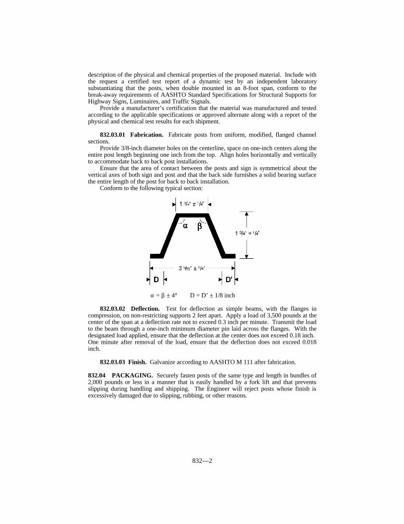
832—2
description of the physical and chemical properties of the proposed material. Include withthe request a certified test report of a dynamic test by an independent laboratorysubstantiating that the posts, when double mounted in an 8-foot span, conform to thebreak-away requirements of AASHTO Standard Specifications for Structural Supports forHighway Signs, Luminaires, and Traffic Signals.
Provide a manufacturer’s certification that the material was manufactured and testedaccording to the applicable specifications or approved alternate along with a report of thephysical and chemical test results for each shipment.
832.03.01 Fabrication. Fabricate posts from uniform, modified, flanged channelsections.
Provide 3/8-inch diameter holes on the centerline, space on one-inch centers along theentire post length beginning one inch from the top. Align holes horizontally and verticallyto accommodate back to back post installations.
Ensure that the area of contact between the posts and sign is symmetrical about thevertical axes of both sign and post and that the back side furnishes a solid bearing surfacethe entire length of the post for back to back installation.
Conform to the following typical section:
α = β ± 4° D = D’ ± 1/8 inch
832.03.02 Deflection. Test for deflection as simple beams, with the flanges incompression, on non-restricting supports 2 feet apart. Apply a load of 3,500 pounds at thecenter of the span at a deflection rate not to exceed 0.3 inch per minute. Transmit the loadto the beam through a one-inch minimum diameter pin laid across the flanges. With thedesignated load applied, ensure that the deflection at the center does not exceed 0.18 inch. One minute after removal of the load, ensure that the deflection does not exceed 0.018inch.
832.03.03 Finish. Galvanize according to AASHTO M 111 after fabrication.
832.04 PACKAGING. Securely fasten posts of the same type and length in bundles of2,000 pounds or less in a manner that is easily handled by a fork lift and that preventsslipping during handling and shipping. The Engineer will reject posts whose finish isexcessively damaged due to slipping, rubbing, or other reasons.

833—1
SECTION 833 SIGN SUBSTRATES
833.01 ALUMINUM.
833.01.01 Panel Signs. Conform to ASTM B 221, Alloy 6063-T6. Fabricate signsfrom 12-inch wide extrusions and, if specified, compatible 6-inch wide extrusions. Whena 6-inch extrusion is specified, use it as the bottom panel of the sign. Typical crosssections and minimum weights per foot are specified in the Plans. Use compatible sideextrusions on all sign edges. Prepare surfaces of extrusions composing the sign face toreceive retroreflective background material according to the extrusion and retroreflectivematerial manufacturers’ recommendations. Provide all remaining surfaces of extrusionsand side extrusions with a soft matte finish.
833.01.02 Sheeting Signs. Conform to ASTM B 209, Alloy 6061-T6 or 5052-H38. Fabricate signs of the size and shape specified. Provide a thickness of 125 mils inch if anysingle edge dimension of the sign exceeds 3 feet. If no single edge dimension exceeds 3feet, provide a thickness of 80 mils. Prepare the side of the sheet to be used as the signface to receive retroreflective background material according to the sheeting andretroreflective material manufacturer’s recommendations.

834—1
SECTION 834 ROADWAY LIGHTING MATERIALS
834.01 WIRING. For all multiple circuit roadway lighting wires use single-conductorAWG copper of sizes specified in the Plans. Use No. 12 AWG copper wire as leads frompole bases or junction boxes to ballast terminals. Use stranded wire, except for groundwires. Ensure that all insulation for No. 8 or larger wire is Type USE (UL rated). Insulation for No. 10 or smaller wire shall be Type THW or THWN. Plainly mark all wireand cable according to the NEC. Use copper grounding conductors sized as specified bythe NEC. Install copper service entrance conductors on the service poles sized andinsulated as specified by the NEC.
834.02 DUCTED CABLE.
A) Cable. Use stranded annealed copper cable conforming to ASTM B 8 and ASTM B33 for operation at 600 volts maximum. Use material that conforms to either theapplicable requirements of ICEA Standard S-19-81, with thermoplastic insulation ofGRS-rubber base conforming to Appendix K(A) of ICEA and listed by UL as TypeUSE for direct burial; or the application requirements of ICEA Standard S-66-524,with thermo-setting insulation of cross link polyethylene conforming to therequirement of Column “A” of ICEA and listed by UL as Type USE. Use cable thatis preinstalled in the duct.
B) Duct. Use polyethylene duct with a minimum tensile strength of 3,100 psi forsecondary cable underground. Provide for 40 percent maximum fill. Conform toASTM D 3485.
834.03 CONDUIT. Except in load bearing areas, use UL rated, schedule 40, PVCconduit. In load bearing areas, use rigid steel conduit that is galvanized inside and out.For underground installation, use conduit of 1 1/4-inch or larger nominal diameter, exceptuse 3/4-inch PVC conduit in the pole bases.
834.04 FUSED CABLE CONNECTOR KIT. Connect lighting fixtures to the feedcircuits with fused cable connector kits. Place each kit in a transformer base, junction box,handhole, or other place as specified in the Contract. Ensure that the fused connector kitcan be repeatedly disconnected without damage to the watertight seals and terminals orwithout reducing the conductivity below specifications. Provide a fused connector kitdesigned to break away without damage.
Use a fused connector kit that completely encloses and protects the fuse againstdamage from water and weather. Use a spring loaded contact between the fuse andfuseholder. Ensure that the springs are not a part of the current carrying circuit. Ensurethat line and load side terminals of the fused connector kit positively connect to theconductors. Insulate and waterproof the terminals according to the manufacturer’srecommendation. Construct the load side housing to retain the fuse when disconnected,and permanently mark it “LOAD” or “LOAD SIDE”.
Use high interrupting capacity type fuses with a rating of 6 amperes. Use 13/32 by 11/2-inch fuses that are rated for 600 volts. Use fuses that protect circuits having a faultcurrent capacity of up to 100,000 amperes AC. Use fuses tested to carry 110 percent oftheir rated capacity and that open at 135 percent in one hour or less.
834.05 LIGHTING STANDARDS. For the design of and materials for all lightingstandards, conform to the AASHTO Standard Specifications for Highway Signs,Luminaires, and Traffic Signals, except as follows. For breakaway signs, and luminairesupports, conform to the breakaway requirements in the AASHTO Standard Specificationsfor Highway Signs, Luminaires, and Traffic Signals, 1985 edition as amended by the“1988 Interim Revisions”, with the modification that the maximum allowable change invelocity is 16 feet per second. Provide lighting standards that consist of a tapered polehaving a base affixed to the lower end, a bracket arm (if required), and a transformer base.

834—2
Furnish an opening near the top of the pole to provide for a cable entrance from the pole tothe bracket arm to provide a smooth cable guide for wiring. Equip the top of the pole witha removable cap. Secure a one-piece anchor base to the lower end of the pole. Provide thisbase with 4 slotted holes to receive the anchor bolts and 4 tapped holes for securing thebolt covers. Provide 4 removable bolt covers with each base.
Use single member bracket arms for 4 and 6-foot mast arm assemblies. Use single ordouble member bracket arms for 8-foot mast arm assemblies. Use double pipe assembliesfor 10, 12, and 15-foot mast arm assemblies. Double pipe assemblies consist of upper andlower members securely joined by means of vertical struts. Provide the pole end of thebracket arm with a cast or plate footing or clamp for positioning the assembly on the pole.
Galvanize the steel structures after fabrication.Ensure that the pole manufacturer provides permanent marking on the pole base or
other suitable location, giving the pole design number and other identification data so thepoles may be compared with material brochures or drawings.
Provide each pole with a suitable handhole to allow access to the pole formaintenance of wiring inside the pole.
834.06 ANCHOR BOLTS. Fabricate anchor bolts from steel having a minimum yieldstrength of 50,000 psi. Provide L-shaped anchor bolts with a minimum length of onemeter, a minimum diameter of one inch, and the horizontal leg at least 4 inches long. Themanufacturer shall specify the correct dimensions; but in no case shall they be less than thedimensions specified above. Provide at least 6 inches of threads and 8 inches ofgalvanizing at the top of the vertical leg. Provide each anchor bolt with 2 galvanized hexnuts. Submit mill test reports on anchor bolts. Protect anchor bolt threads from damageduring shipping.
834.07 TRANSFORMER BASES. Conform to the AASHTO Standard Specificationsfor Structural Supports for Highway Signs, Luminaires and Traffic Signals. Ensure thateach base has the following minimum outside dimensions: 17 inches high, 15 by 15-inchsquare bottom and 12 by 12-inch square top. Ensure that bases have a trapezoidal doorwith the following minimum dimensions: 11 inches high, 9 inches across the bottom, and7.5 inches across the top. Construct the door of a high density polyethylene material in acolor that matches the base. Provide each base with 4 loose bearing plates (anchorwashers) and nuts to fasten the base to the anchor bolts. Fasten each transformer base tothe base flange of the pole with 4 loose galvanized bearing plates and 4 galvanized steelconnecting bolts and nuts. Use connecting bolts of the same diameter and strength as theanchor bolts. Submit mill test reports on the connecting bolts. The manufacturer shallspecify the bolt circle and physical dimensions of the base bottom to ensure a properfoundation fit. Provide each transformer base with a 1/2-inch 13 UNC tapped hole orother suitable provisions for grounding purposes.
834.08 MARKERS FOR BURIED CONDUIT. Use 36 by 4 by 4-inch concrete postsreinforced with 4 No. 3 deformed steel bars. The Department will allow the use ofstandard rural right-of-way markers in lieu of conduit markers.
834.09 CONCRETE. Conform to Subsection 601.02 and 601.03. Use Class Aconcrete.
834.10 PAINTS. Use commercially available rust inhibiting primer for the prime coat. Use aluminum paint conforming to AASHTO M 69, or equal, for the intermediate andfinish coats.
834.11 BALLASTS. Provide only high-pressure sodium luminaire ballasts that operatein a single circuit of the specified voltage ± 10 percent.
834.12 LUMINAIRES. Provide IES distribution as specified in the Contract; 2-inchslip-fitter mounting; and constant wattage type transformers.

834—3
Type A - 100 watt high-pressure sodium horizontal roadway luminairesType B - 150 watt high-pressure sodium horizontal roadway luminairesType C - 250 watt high-pressure sodium horizontal roadway luminairesType D - 400 watt high-pressure sodium horizontal roadway luminaires
Use luminaires that provide light levels conforming to AASHTO’s An InformationalGuide for Roadway Lighting. When submitting brochures for suggested luminaires,include iso lux curves, IES type distribution, lamp lumens, and typical ballast factor usedfor each type of luminaire. Submit the photometric data in IES format on an IBMcompatible 3 1/2-inch floppy disk to the Central Office, Division of Traffic. Include withthe submittal a point of contact and phone number to answer technical questions about theluminaire.
834.13 LAMPS. Provide only high-pressure sodium lamps with the followingminimum initial light output:
Type A - 9 500 lmType B - 16 000 lmType C - 25 000 lmType D - 50 000 lm
834.14 MAGNETIC CONTACTORS AND CONTROL TRANSFORMERS. Provide only magnetic contactors that are 2 pole, sized as specified in the Contract, andhave a 120 volt coil. Protect each contactor coil by a 15 amp fuse. Equip contactors withcontrol switches for both automatic and manual actuation. Provide photoelectric switchesfor automatic actuation. Use photoelectric controls that are solid state cadmium sulfidetype designed for use in 120 volts 60 Hz circuits and rated for 1,000 watts resistive load. Use photoelectric controls with built-in surge protection and designed to provide an outputcircuit closure when photoelectric control components fail. Provide photoelectric controlsand mounting bases that are twist-lock type. Provide 2 pole, double throw switches thatmanually actuate. Ensure that each switch has minimum rating of 125 volts, 15 amperes.
Use control transformers that are 1 KVA, single phase, 240/480 volt primary,120/240 volt secondary, dry type, 60 Hz, with primary winding isolated from secondarywinding. Use transformers that are capable of indoor or outdoor installation and have amaximum temperature rise of 99 °F at 104 °F ambient temperature.
834.15 DISTRIBUTION TRANSFORMERS. Equip all distribution transformerswith 2, 2.5 percent taps above and below rated primary voltage. Provide transformers thatare protected by a primary lightning arrester with an indicating fuse cutout of the voltageand amperage as specified in the Plans.
834.16 SECONDARY LIGHTNING ARRESTERS. Provide only secondarylightning arresters designed for use with the specified voltage and rated at 0-650 voltsRMS.
834.17 WEATHERPROOF ENCLOSURES. Fabricate enclosures from 125-mil orthicker natural finished aluminum. Provide enclosures with a No. 2 Corbin lock and keys.Install a 120 VAC GFI duplex receptacle in the enclosure with a separate 20 amp breaker.
834.18 GROUND RODS. Provide only composite shaft ground rods consisting of apure copper exterior that has been inseparably molten welded to a steel core. Use rodswith a minimum diameter of 1/2 inch and a minimum length of 8 feet. Equip the rodswith copper or bronze clamps.
834.19 WOOD POLES. Use Class 4 poles, of the length specified in the Contract,conforming to Subsection 820.

835—1
SECTION 835 TRAFFIC CONTROL DEVICES
835.01 DESCRIPTION. This section defines minimum acceptable design andoperational standards for traffic control devices used in the Commonwealth.
835.02 TIME CLOCKS. Use time clocks that are solid state, microprocessor basedunits with one to 4 relay outputs rated at 10 amps, 115 VAC resistive load. Connect allrelay contacts and clock power through a 16 pin circular plastic connector (Amp#520258-3 or approved equal). Pin designations are as follows:
Pin No. Function Pin No. Function1 Line 9 #4 Com2 Neutral 10 #1 N.O.3 Ground 11 #3 Com4 #1 Com 12 #3 N.C5 #1 N.C 13 #3 N.O.6 #2 Com 14 #4 N.C.7 #2 N.O. 15 #4 N.O.8 No Con. 16 #2 N.C.
Operate clocks with a supply voltage from 95 to 135 VAC, 60 Hz at temperaturesfrom -29 to + 165 °F.
Supply backup power for the clock with a battery or capacitor. Ensure that backuppower maintains time keeping and program steps for at least 48 hours.
Enter all programming through the keyboard. Ensure that programming featuresinclude at least 32 program steps. Ensure that each step shall program a single relayoutput by hour and minute and allow a single day of week, Monday through Friday orSaturday and Sunday to be set. Provide clocks that have automatic daylight savings timeadjustment as default with a daylight savings time override option controlled from thekeyboard. Provide clocks that have manual override capability for each relay. Provideclocks that have a self test function which exercises relay outputs. Ensure that units areenclosed in a durable case that can mount on a vertical surface. Supply each unit with afemale mating harness with 3-foot wires. Wire the harnesses for the number of relays usedin the clock. Label each wire one foot from the plug with permanent non-fading wirelabels indicating the wire function.
835.03 PEDESTRIAN PUSHBUTTON DETECTORS. Provide a pedestriandetector that consists of a single plunger push button control switch with a 2 1/4-inch(minimum) chrome plated mushroom shaped plunger. Provide a 5-A (minimum), 110VAC switch with 2 circuit (NO/NO) slow make contacts. Ensure that pushing of thebutton closes both NO circuits. Use a switch body that is die cast and painted with a blackwrinkle finish paint. Include a neoprene gasket for sealing the switch body to theenclosure.
835.04 EQUIPMENT TESTING. The Department requires that each purchasedindividual cabinet, controller, conflict monitor, modem, and loop amplifier isenvironmentally tested. At a minimum, test each unit purchased according to “TrafficSignal Control Equipment Specifications” by the California Department of Transportation. The manufacturer is free to suggest additional tests or variations in the above proceduresthat may be part of an existing quality control program.
A representative of the Department may travel to the testing site to verify that theenvironmental testing is being carried out properly and to observe manufacturing practicesused at the factory. The manufacturer shall submit a proposed testing procedure andschedule 30 calendar days in advance for evaluation by the Department. Ensure that the

835—2
test procedures, environmental chambers, automatic test equipment, display boards, powersupplies, and controls are described in detail. Resolve any problems in the testingprocedure before the representative arrives.
Test cabinets at ambient room temperature. Use an automatic or semi-automaticmethod for checking cabinet wiring between equipment harnesses.
835.05 SIGNALS AND BEACONS.
835.05.01 Fittings and Mounting. Supply all traffic control signals, beacons, andlane control signals, unless otherwise specified, with necessary fitting including wireentrance fittings and swivel type balance adjuster for span wire mounting. Design wireentrance fitting to prevent entrance of water when using normal drip loops. Galvanize orcadmium plate span wire clamps and bolts.
Ensure that the total loose play rotational tolerance between span wire clamp and wireentrance fitting, with swivel adjuster assembled, is not more than 3 degrees.
Use mounting arms and brackets made of 1 1/2-inch standard metal IPS pipe. TheDepartment will allow cast or fabricated bottom brackets.
Ensure that signals are adjustable, and arrange them so that each face may be rotatedto and positively locked within not more than 5 degrees of any position in the horizontalplane. Use a separate locking ring mating with serrations cast or molded into the signalhousing. Do not use serrations cast into the wire outlet body. Use a locking ring designedwith a minimum of 2 pins or tabs to mate with corresponding holes or notches in the wireoutlet body. Use locking rings that are machined to provide sharp, well formed serrationsthat exactly match the serrations in the signal housing.
835.05.02 Housings. Provide metal housings cast from a non-ferrous, non-corrosivealuminum alloy. Use parts that are fitted with rubber or neoprene type gaskets to provideweather tight seals. Use housing sections of the same type and make of manufacturer thatare interchangeable. Reinforce tops and bottoms to which supporting attachments arefastened to prevent breakage from vibration and shock.
Use polycarbonate signals that are the same in appearance as cast aluminum signals,except mold the housings, doors, and visors from polycarbonate resin to withstand a 70foot-pound impact without fractures or permanent deformation. Ensure that the color ishomogeneous throughout.
Use doors of the same material as the housing. Ensure that doors are suitably hingedand held securely to the housing by simple locking devices, which do not require tools ofany kind for opening. Use stainless steel hinge pins, lens clips, etc.
835.05.03 Optical Units. Each optical unit is a complete assembly of lampreceptacle, reflector, cover glass or lens, and door with all necessary supporting parts andwith a single signal indication. Conform in all respects, except as further restricted by thissection, to the standards of the Institute of Traffic Engineers (ITE).
Provide incandescent illuminated optical units that contain a heat resistant lampreceptacle positioned to provide a light center at the focal point of the reflector. Usereflectors that are “ALZAK” process coated aluminum or other approved equal. Use a650-watt standard traffic signal lamp in an 8-inch traffic signal, 9-inch pedestrian signal,or 12-inch one-section pedestrian signal. Use a 1 950-lumen standard traffic signal lampin a 12-inch traffic signal, lane control signal, or 12-inch pedestrian signal.
Construct and mount optical units to provide easy access for all maintenance andrepairs including wiring within the signal housing. Design optical units so that the use oftools of any kind are not required for replacing signal lamps.
Wire and connect each lamp receptacle to a suitable terminal block within the signalhousing with minimum No. 18 AWG, 194 °F, 600 volt, color-coded, stranded fixture wire. Do not use braided wire. Locate the terminal block in the second section from the top inmulti-section faces.
Use glass lenses. Ensure that lenses of the same nominal diameter areinterchangeable regardless of manufacturer.

835—3
Each signal face contains one or more complete optical units in suitable housings forcontrol in one direction only and is designated as one-section, 2-section, 3-section, etc.
835.05.04 Signal Heads. Each signal head contains one or more signal faces and isdesignated as one-way, 2-way, 3-way, etc.
One-section signals are standard flashing beacons. For one-way and two-wayflashing beacons, supply signal heads with amber or red lenses as specified in theContract. Mount signals with 2 or more sections vertically with indications positionedaccording to the MUTCD.
Fit each optical unit with a visor or hood. Provide combination or tunnel type visorsthat enclose at least 80 percent of the lens circumference for amber lenses. Supplystandard visors that enclose at least 50 percent of the lens circumference for all red orgreen lenses. Supply visor lengths that are approximately the same as the lens diameterand designed to minimize sun phantom. Attach hoods with screws. Do not use snap inhoods.
Ensure that 8-inch signals display circular indications of not less than 7 3/4 inches indiameter. Ensure that 12-inch signals display circular indications of not less than 11 1/2inches in diameter.
Ensure that signal sections of both 12-inch and 8-inch signals of the same make ormanufacture are interchangeable to provide for optional combinations of lens sizes. Usetops and bottoms of signals that have circular openings for 1 1/2-inch IPS rigid pipe, anduse replaceable tops and bottoms that are interchangeable. Close all unused openings withremovable plugs and caps.
Use signal heads that are assembled and wired. Supply visors, brackets, backplates,hangers, etc. that are packaged and shipped within the same carton as the signal head forwhich they are being supplied, with or without them attached to the signal.
835.05.05 Pedestrian Signals. Use pedestrian signals that consist of a one-piece diecast aluminum housing. Use a housing that has 1 1/2-inch holes in top and bottom forpost top or bracket mounting. These indications consist of the illuminated symbols of awalking person (symbolizing WALK) and an upraised hand (symbolizing DON’TWALK).
Use signal heads that are assembled and wired. Supply brackets, arms, wire entrancefittings, and all other necessary hardware that are packaged and shipped within the samecarton as the signal head for which they are being supplied with and without them attachedto the signal.
835.05.06 Painting. Paint all signals and beacons (except black polycarbonate),arms and braces, brackets, trunions, wire entrance fittings, sign housings, etc. black with 2coats of high grade exterior gloss enamel. Paint the inside of all hoods and visors dullblack to minimize glare reflections.
Prepare, degrease, and prime all painted surfaces before painting to prevent chippingand peeling.
Ensure that all miscellaneous hardware is corrosion resistant, or galvanize or plate itafter any drilling, threading, or welding.
835.06 TRAFFIC LOOP ENCAPSULANT. Provide a non-shrink, non-stringing,moisture cure, one-part, polyurethane traffic loop encapsulant suitable for use in bothasphalt and concrete pavements. Ensure it provides a void-free encapsulation for detectorloop wires and adequate compressive yield strength and flexibility to withstand heavyvehicular traffic and normal pavement movement. The Engineer may reject the product ifany physical property renders the material unsuitable.
Ensure that the cured encapsulant has the following properties:

835—4
TRAFFIC LOOP ENCAPSULANT REQUIREMENTSAND PRICE ADJUSTMENT SCHEDULE
Test Specification 100% Pay 90% Pay 80% Pay 70% Pay 50% Pay(1)
Hardness 25-29 20-24 15-19 ≤ 14(ASTM D 2240) 35-65 30-70 71-75 76-80 81-85 ≥ 86
Tensile Strength, psi
(ASTM D 412) 150 min. 145 min. 140-144 135-139 130-134 ≤ 129
Elongation, %(2)
(ASTM D 412) 125 min. 120 min. 115-119 110-114 105-109 ≤ 104
Density, lb/gal 8.30-8.49 8.20-8.29 8.10-8.19 ≤ 8.09
(ASTM D 1875) 9.00-11.00 8.50-11.50 11.51-11.60 11.61-11.70 11.71-11.80 = 11.81
Tack-free Time, hours
(ASTM C 679) 24 max. 24.5 max. 24.6-25.0 25.1-25.5 25.6-26.0 ≥ 26.1
Complete Dry Time,
hours (KM 64-447) 30 max. 30.5 max 30.6-31.0 31.1-31.5 31.6-32.0 ≥ 32.1
Chemical Interactions:
(KM 64-446)
Motor Oil No Effect
Deicing Chemicals No Effect
Gasoline Slight Swell
Hydraulic Brake Fluid No Effect(1) If allowed to remain in place, the Department will review materials
performing in this range on a project-by-project basis to determine ifremoval of the material is warranted.
(2 Tested at a 2- inch per minute pull rate.
Use one-quart tubes of loop sealant that are suitable for use with a standard caulkinggun. Provide each tube with a plastic nozzle to facilitate placing of the material in thepavement slot.
835.07 WARRANTIES. Warranty equipment for a period of 6 months, or provide themanufacturer’s standard warranty, whichever is greater.
835.08 DOCUMENTATION. With each unit purchased under this section include onedocumentation package consisting of:
1) A complete instruction manual.2) A complete step by step explanation of circuit theory and operation.3) A complete schematic.4) A complete parts layout. Parts identification may be silk-screened directly on circuit
board.5) All point to point voltages and wave forms pertinent to proper servicing. This
information may be included on the schematic diagram.6) Complete installation procedures for the unit.7) A complete parts list with full information as to availability of any custom or
nonstandard parts.8) All applicable warranties and guarantees.

836—1
SECTION 836 DURABLE PREFORMED PAVEMENTMARKINGS TYPE I TAPE
836.01 TYPE I TAPE. Use preformed pavement marking material consisting of whiteor yellow films with glass beads incorporated to provide immediate and continuingretroreflection.
Use preformed pavement marking material capable of adhering to new dense andopen graded asphalt surfaces, during the paving operation, or portland cement concrete bya pre-coated pressure sensitive adhesive. The Engineer may require a primer toprecondition the pavement surface. Ensure that the markings conform to pavementcontours by the action of traffic. Ensure that, after application, the markings areimmediately ready for traffic.
Ensure that these markings provide long term reflectivity, as determined in thefollowing performance requirements, when applied according to the manufacturer’sinstructions.
Ensure that the preformed markings are suitable for use one year after the date ofreceipt when stored according to the manufacturer’s recommendations.
A) Composition. Use retroreflective preformed pavement markings consisting of amixture of high quality polymeric materials, pigments, and glass beads distributedthroughout its base cross sectional area.
B) Reflectance. Ensure that the white and yellow markings have the following initialminimum reflectance values as measured according to the testing procedures ofASTM D 4061. Measure the specific luminance (SL), and express it as millicandelasper lux per square meter. Use a test distance of 30 meters and a sample size of a 24by 30-inch rectangle.
C) Skid Resistance. Ensure that the surface of the retroreflective material provides aninitial minimum skid resistance value of 45 BPN when tested according to ASTM E303.
D) Patchability. Ensure that the pavement marking material is capable of use forpatching worn areas of the same type according to the manufacturer’srecommendations.
E) Material Warranty. For a period of 48 months from the date of installation,regardless of ADT and under normal traffic conditions, the manufacturer will providereplacement material for any material used as longitudinal markings that (1) fails toretain the minimum reflectivity values (minimum replacement zone is 300 feet ofroadway length), or (2) fails due to loss of adhesion or complete wear through.
The Department will take measurements according to KM 64-202 or KM64-203. The minimum reflectivity requirements, as measured with a LTL2000retroreflectometer or mobile 30M geometry device, are as follows:
White: 200 mcd/lux/square meterYellow: 150 mcd/lux/square meter
INITIAL REFLECTANCE
Color Entrance Observation SpecificAngle Angle Luminance
White 86.5º 1.0º 700 minimumWhite 86.0º 0.2º 1,100 minimumYellow 86.5º 1.0º 500 minimumYellow 86.0º 0.2º 800 minimum

836—2
F) Testing and Acceptance. Furnish the manufacturer’s typical test analysis for thedurable preformed pavement markings and the manufacturer’s certification statingthat the material conforms to this section.
The Engineer will submit the above documentation, accompanied by a SampleIdentification Form to the District Materials Engineer. The Department will baseacceptance on a review of the test data, a certification statement, and initial fieldevaluation.

837—1
SECTION 837 EXTRUDED THERMOPLASTIC PAVEMENTMARKING MATERIALS
837.01 PRE-MIX BEADS. Supply the thermoplastic material with pre-mix beads. The gradation and coating are at the manufacturer’s discretion. Include the selectedgradation on the product certification so that the Department may analyze the verificationsamples.
837.02 DROP ON BEADS. Use beads that will ensure the pavement marking materialwill meet retroreflectivity requirements. The Department will evaluate the beads as part ofthe marking system through retroreflectivity readings.
837.03 THERMOPLASTIC MATERIAL. Use a maleic-modified glycerol ester resin(alkyd binder) to formulate the thermoplastic material. Use material that, when heated,does not exude fumes that are toxic or injurious to persons or property.
837.03.01 Composition. Ensure that the pigment, beads, and filler are uniformlydispersed in the resin. Use material that is free from all skins, dirt, and foreign objects,and conforms to following table.
(1)Use a binder that consists of a mixture of synthetic resins, at least one beingsolid at room temperature, and high boiling point plasticizers. Ensure that atleast one-third of the binder composition is solid maleic-modified glycerolester resin and is not less than 8 percent by weight of the entire materialformulation. Do not use alkyd binder that contains petroleum basedhydrocarbon resins.
(2)The manufacturer may choose the amount of calcium carbonate and inertfillers, providing all other requirements of this section are met.
837.03.02 Physical Characteristics.
A) Specific Gravity. Do not exceed 2.3.B) Color. For thermoplastic material heated for 4 hours at 425 °F under agitation,
conform to the following luminosity and color requirements:
1) Luminosity. - Daylight reflectance at 45 degrees entrance angle, 0 degreesobservation angle.
White - 75 percent minimum. Yellow - 45 percent minimum. 2) Color - Conform to the CIELAB color coordinates defining yellow and white
as determined with a spectrophotometer using a D65 illuminant with a 45degree entrance angle and 0 degree observation angle geometry.
COMPOSITION(Percentage by Weight)
Component White YellowBinder, (1) 18.0 min. 18.0 min.Glass Beads (Premixed) 30 - 40 30 - 40Titanium Dioxide 10.0 min. —Calcium Carbonate & Inert Fillers (2) 42.0 max. 50.0 max.Lead Chromate 0.0 max. 4.0 min.

837—2
CIELAB COLOR COORDINATESYellow White
L* 80.80 94.92a* 19.04 -2.18b* 88.57 3.10Allowable Variation 2.0 ? E Maximum 2.0 ? E Maximum
C) Set Time. Use material that, when applied at a temperature range of 415 ± 15 ºFand thickness of 40 to 120 mils, sets to bear traffic in not more than 2 minuteswhen the air and road surface temperature is approximately ≥ 50 ± 3 ºF, and notmore than 10 minutes when the air and road surface temperature isapproximately < 50 ± 3 ºF.
D) Bond Strength. After heating the thermoplastic material for 4 hours at 425 ºF,ensure that the bond strength to concrete exceeds 180 psi, according to ASTM D4796.
E) Cracking Resistance at Low Temperature. After heating the thermoplasticmaterial for 4 hours at 425 ºF, applying it to concrete blocks, and cooling it 46 ºF,ensure that the material shows no cracks when observed from a distanceexceeding one foot.
F) Impact Resistance. After heating the thermoplastic material for 4 hours at425 ºF and forming test specimens, ensure that the impact resistance is aminimum of 1.13 joules.
G) Softening Point. After heating the thermoplastic material for 4 hours at 425 ºFand testing according to ASTM D 36, ensure that the materials have a softeningpoint of 215 ± 15 ºF.
H) Flowability. After heating the thermoplastic material for 4 hours at 425 ºF andtesting for flowability, ensure that the white thermoplastic has a maximumresidue of 18 percent and the yellow thermoplastic has a maximum residue of 21percent.
I) Yellowness Index. Use white thermoplastic material that does not exceed ayellowness index of 0.15.
J) Flowability (Extended Heating). After heating and stirring the thermoplasticmaterial for 8.5 hours at 425 °F and testing for flowability, ensure that thethermoplastic has a maximum residue of 28 percent.
K) Flash Point. Use thermoplastic material that has a flash point not less than475 °F when tested according to ASTM D 92.
L) Storage Life. Ensure that the material conforms to this section for a period ofone year. The thermoplastic must also melt uniformly with no evidence of skinsor unmelted particles for this one year period. The manufacturer shall replaceany material not conforming to the above requirements.
837.03.03 Certification, Testing and Approval.
A) Sampling. The manufacturer shall perform tests on a minimum of onecomposite sample per lot of thermoplastic produced. Provide a composite samplecomposed of equal portions of randomly selected samples taken from each10,000 pounds during the lot’s production. Use a lot size of approximately44,000 pounds unless the total order is less than this amount. Ensure that theone quart composite sample is collected by an independent laboratory approvedby the Division of Materials.
B) Testing. The manufacturer shall perform the following tests on the thermoplasticpavement marking material: Color, Reflectance and Yellowness Index, BondStrength (Yellow and White), Low Temperature Stress Resistance, ImpactResistance, Softening Point, Flowability, Flowability (Extended Heating), DryingTime and Specific Gravity.

837—3
C) Submission. Before shipment of the thermoplastic material, the manufacturershall submit to the Division of Materials a 1/2-gallon composite sample of thethermoplastic material, a copy of the manufacturer’s test results, a listing of thetheoretical composition of the thermoplastic material (see Composition table inSubsection 837.03.01) and a signed statement of certification that includes thefollowing information:
1) A statement that the thermoplastic material complies with all requirementsof this section.
2) The quantity of material represented in the lot or batch.3) The destination of the shipment.
D) Verification. The Department reserves the right to verify the manufacturer’s testresults by conducting any or all of the tests listed above. The Division ofMaterials or an approved independent laboratory will perform this testing at theDepartment’s expense and according to AASHTO T 250 and Kentucky StandardTest Methods. Upon completion of testing, the Division of Materials will notifythe supplier of approval and forward copies of the material’s certification andapproval to the Division of Traffic.
837.03.04 Packaging. Package thermoplastic pavement marking material insuitable 50-pound containers to which it shall not adhere during shipment or storage. Include a label stating that the material is to be maintained within a temperature range of400-440 ºF during application. Provide the thermoplastic material in either block orgranular form.

838—1
SECTION 838 FLEXIBLE DELINEATOR POSTS
838.01 GENERAL. Furnish surface and ground mounted flexible delineator posts fromthe Department’s List of Approved Materials. The Department will approve flexibledelineators based upon their NTPEP performance evaluation. The Department considersthe flexible delineator posts to include the post, reflective element, and mountinghardware.
838.02 PACKAGING. Securely fasten posts of the same type and length in bundles of2,000 pounds or less in a manner that is easily handled by a fork lift and that preventsslipping during handling and shipping. The Engineer will reject posts with excessivelydamaged finishes.

839—1
SECTION 839 KY TYPE I GLASS BEADS
839.01 GLASS BEADS. Use for application to reflective pavement markings. Conform to AASHTO M 247, moisture resistant specifications with the followingadditional requirements for gradation and percentage of rounds:
Gradation: Sieve Size Percent PassingNo. 20 98-100No. 30 70-90No. 40 —No. 50 0-20No. 80 0-5
Rounds: 70% minimum for + 50 beads
839.01.01 Sampling. The Department will obtain random samples of all shipmentsthat are intended for use by State Traffic Forces at the point of delivery. The Departmentwill evaluate the beads for acceptance prior to use. The Department will accept beads forContractor use based upon manufacturer certification.
839.01.02 Testing. The Department will test according to AASHTO M 247 and thefollowing.
A) Chemical Resistance Test. Place three, 0.1 to 0.2-ounce, samples of the beadsin separate Pyrex-glass beakers or porcelain dishes. Cover one sample withdistilled water; one with a 3N solution of sulfuric acid; and one with a 50 percentsolution of sodium sulfide. Examine the samples microscopically after one hourof immersion. Reject the beads if they darken or “frost”.
B) Moisture Resistance Test. Place approximately 2 pounds of glass beads in aclean cotton bag not treated with sizing material. Immerse the bag in water,completely covering the beads, for approximately 30 seconds. Remove the bagand wring free of excess water. Hang the bag in room air for 2 hours to dry. Transfer the beads slowly to a clean, dry, standard (4-inch stem, and a 1/4-inchdiameter exit) glass funnel. Accept beads that flow freely through the funnel.
839.01.03 Approval. The Department will notify the vendor of acceptance when alltesting is complete. The Department will evaluate beads used by the Contractor as part ofthe painted line by use of hand-held or mobile retroreflectance readings.

840—1
SECTION 840 RAISED MARKERS
840.01 TYPE IV MARKERS. Provide markers from the Department’s List ofApproved Materials. Type IV markers are replacement lenses for use in Type V markercastings.
840.02 TYPE V MARKERS. Provide markers from the Department’s List of ApprovedMaterials. Type V markers consist of an iron casting with a Type IV marker (mono or bi-directional) attached.
840.03 TYPE IVA MARKERS. Provide markers from the Department’s List ofApproved Materials. Type IVA markers are surface mounted lenses for temporary use inwork zones.
840.04 SAMPLING. Obtain a manufacturer’s certification for each shipment. Includewith each shipment of adhesive a written statement from the manufacturer certifying that itconforms to the recommendations of the marker manufacturer, and stating the minimumtemperature the adhesive can be satisfactorily mixed and applied.
840.05 PACKAGING. Suitably and substantially package all materials with the nameand address of the manufacturer and vendor, contract or purchase number, kind ofmaterial, trade name, and net contents plainly marked on each package.

841—1
SECTION 841 —LATEX ADMIXTURE
841.01 DESCRIPTION. This section covers latex admixtures for concrete bridge deckoverlays.
841.02 REQUIREMENTS. Select a latex admixture from the Department’s List ofApproved Materials. Use a latex admixture that is produced in the United States.
Manufacturers desiring prequalification of new products shall have their producttested and evaluated by a qualified independent laboratory, or the Department’s Divisionof Materials, according to the Prequalification Test Program in the U.S. Department ofTransportation Research Report No. FHWA-RD-78-35. When analysis is performed byan independent laboratory, the manufacturer shall submit the certified test results alongwith a 5-gallon sample of the latex admixture to the Department’s Division of Materials. The Department will approve the latex admixture based upon the submitted informationand evaluation of the sample.
Use only latex admixtures that are free of chlorides.Include with each shipment of latex admixture a report of tests performed according to
the Certification Program in Report No. FHWA-RD-78-35. In addition to actual testresults, include in the report the date of manufacture, batch or lot number(s), quantityrepresented, manufacturer’s name, place of manufacture, a statement that all test resultsare satisfactory, the date the one-year certification period will expire, and signature ofmanufacturer’s representative.
The Department will check sample and test each lot of latex and will remove it fromthe list of approved materials at any time there is an indication of nonconformity orquestionable quality.
Package and store the latex admixture in containers and storage facilities that protectthe material from freezing and from temperatures above 85 °F. When storing outside ofbuildings during moderate temperatures, keep the material shaded and away from directsunlight. Do not use any latex admixture exposed to freezing temperatures withoutapproval from the Division of Materials.
842—1
SECTION 842 PAVEMENT STRIPING PAINT
842.01 DESCRIPTION. This section covers quick-drying pavement striping paint forpermanent applications.
842.02 APPROVAL. Select materials that conform to the composition requirementsbelow. Submit initial samples for approval before beginning striping operations. Theinitial sample may be sent from the manufacturer of the paint. The Department willrandomly sample and evaluate the paint each week that the striping operations are inprogress.
PAINT COMPOSITIONProperty and Test Method Yellow White
Color (CIELAB)Spectrophotometer using aD65 illuminant at 45°illumination and 0° viewingwith a 2° observer
L* 80.80a* 19.04b* 88.57
With a maximum variationof 2.0 ∆Ecmc
L* 94.92a* -2.18b* 3.10
With a maximum variationof 2.0 ∆Ecmc
LeadASTM D 3335
< 5ppm <5ppm
TiO2
ASTM D 4764NA 10% by wt. of pigment min.
VOCASTM D 2369 and D 4017
1.25-lb/gal max. 1.25-lb/gal max.
Contrast Ratio(at 15 mils wft.)
0.97 0.99
842.03 ACCEPTANCE PROCEDURES FOR NON-SPECIFICATIONPAVEMENT STRIPING PAINT. When non-specification paint is inadvertentlyincorporated into the work the Department will accept the material with a reduction in pay. The percentage deduction is cumulative based on its compositional properties, but will notexceed 60 percent. The Department will calculate the payment reduction on the unit bidprice for the routes where the non-specification paint was used.
PAVEMENT STRIPING PAINT REDUCTION SCHEDULE
Non-conforming Property Color Lead TiO2 VOC ContrastReduction Rate 10% 60% 10% 60% 10%
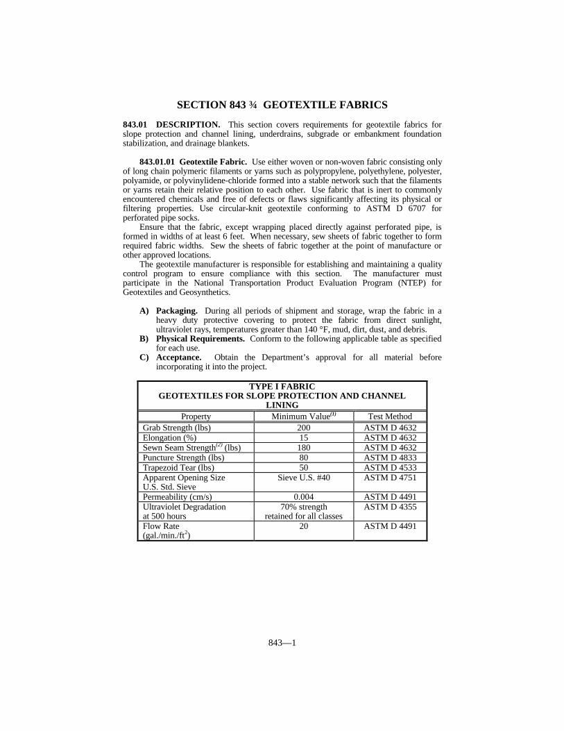
843—1
SECTION 843 GEOTEXTILE FABRICS
843.01 DESCRIPTION. This section covers requirements for geotextile fabrics forslope protection and channel lining, underdrains, subgrade or embankment foundationstabilization, and drainage blankets.
843.01.01 Geotextile Fabric. Use either woven or non-woven fabric consisting onlyof long chain polymeric filaments or yarns such as polypropylene, polyethylene, polyester,polyamide, or polyvinylidene-chloride formed into a stable network such that the filamentsor yarns retain their relative position to each other. Use fabric that is inert to commonlyencountered chemicals and free of defects or flaws significantly affecting its physical orfiltering properties. Use circular-knit geotextile conforming to ASTM D 6707 forperforated pipe socks.
Ensure that the fabric, except wrapping placed directly against perforated pipe, isformed in widths of at least 6 feet. When necessary, sew sheets of fabric together to formrequired fabric widths. Sew the sheets of fabric together at the point of manufacture orother approved locations.
The geotextile manufacturer is responsible for establishing and maintaining a qualitycontrol program to ensure compliance with this section. The manufacturer mustparticipate in the National Transportation Product Evaluation Program (NTEP) forGeotextiles and Geosynthetics.
A) Packaging. During all periods of shipment and storage, wrap the fabric in aheavy duty protective covering to protect the fabric from direct sunlight,ultraviolet rays, temperatures greater than 140 °F, mud, dirt, dust, and debris.
B) Physical Requirements. Conform to the following applicable table as specifiedfor each use.
C) Acceptance. Obtain the Department’s approval for all material beforeincorporating it into the project.
TYPE I FABRICGEOTEXTILES FOR SLOPE PROTECTION AND CHANNEL
LININGProperty Minimum Value(1) Test Method
Grab Strength (lbs) 200 ASTM D 4632Elongation (%) 15 ASTM D 4632Sewn Seam Strength(2) (lbs) 180 ASTM D 4632Puncture Strength (lbs) 80 ASTM D 4833Trapezoid Tear (lbs) 50 ASTM D 4533Apparent Opening SizeU.S. Std. Sieve
Sieve U.S. #40 ASTM D 4751
Permeability (cm/s) 0.004 ASTM D 4491Ultraviolet Degradationat 500 hours
70% strengthretained for all classes
ASTM D 4355
Flow Rate(gal./min./ft2)
20 ASTM D 4491

843—2
TYPE II FABRICGEOTEXTILES FOR UNDERDRAINS
(except pavement edge drains)Property Minimum Value(1) Test Method
Grab Strength (lbs) 80 ASTM D 4632Elongation (%) N/A ASTM D 4632Sewn Seam Strength(2) (lbs) 70 ASTM D 4632Puncture Strength (lbs) 25 ASTM D 4833Trapezoid Tear (lbs) 25 ASTM D 4533Apparent Opening SizeU.S. Std. Sieve
Sieve U.S. #50 ASTM D 4751
Permeability (cm/s) 0.010 ASTM D 4491Ultraviolet Degradationat 150 hours
70% strengthretained for all classes
ASTM D 4355
Flow Rate(gal./min./ft2)
50 ASTM D 4491
TYPE III FABRICGEOTEXTILES FOR SUBGRADE OR EMBANKMENT
STABILIZATION
Property Minimum Value(1) Test MethodGrab Strength (lbs) 180 ASTM D 4632Elongation (%) N/A ASTM D 4632Sewn Seam Strength(2) (lbs) 160 ASTM D 4632Puncture Strength (lbs) 67 ASTM D 4632Trapezoid Tear (lbs) 67 ASTM D 4533Apparent Opening SizeU.S. Std. Sieve
U.S. #40 ASTM D 4751
Permeability (cm/s) 0.002 ASTM D 4491Ultraviolet Degradation at150 hours
70% strengthretained for all classes
ASTM D 4355
Flow Rate(gal./min./ft2)
7 ASTM D 4491
TYPE IV FABRICGEOTEXTILES FOR EMBANKMENT DRAINAGE BLANKETS
AND PAVEMENT EDGE DRAINSProperty Minimum Value(1) Test Method
Grab Strength (lbs) 180 ASTM D 4632Elongation (%) N/A ASTM D 4632Sewn Seam Strength(2) (lbs) 160 ASTM D 4632Puncture Strength (lbs) 80 ASTM D 4833Trapezoid Tear (lbs) 50 ASTM D 4533Apparent Opening SizeU.S. Std. Sieve
U.S. #50 ASTM D 4751
Permeability (cm/s) 0.008 ASTM D 4491Ultraviolet Degradationat 150 hours
70% strengthretained for all classes
ASTM D 4355
Flow Rate(gal./min./ft2)
40 ASTM D 4491
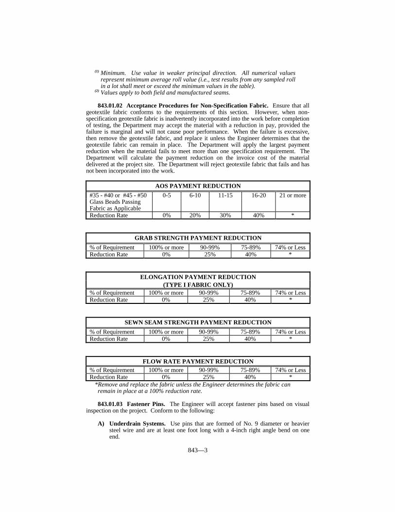
843—3
(1) Minimum. Use value in weaker principal direction. All numerical valuesrepresent minimum average roll value (i.e., test results from any sampled rollin a lot shall meet or exceed the minimum values in the table).
(2) Values apply to both field and manufactured seams.
843.01.02 Acceptance Procedures for Non-Specification Fabric. Ensure that allgeotextile fabric conforms to the requirements of this section. However, when non-specification geotextile fabric is inadvertently incorporated into the work before completionof testing, the Department may accept the material with a reduction in pay, provided thefailure is marginal and will not cause poor performance. When the failure is excessive,then remove the geotextile fabric, and replace it unless the Engineer determines that thegeotextile fabric can remain in place. The Department will apply the largest paymentreduction when the material fails to meet more than one specification requirement. TheDepartment will calculate the payment reduction on the invoice cost of the materialdelivered at the project site. The Department will reject geotextile fabric that fails and hasnot been incorporated into the work.
AOS PAYMENT REDUCTION#35 - #40 or #45 - #50 0-5 6-10 11-15 16-20 21 or moreGlass Beads PassingFabric as ApplicableReduction Rate 0% 20% 30% 40% *
GRAB STRENGTH PAYMENT REDUCTION
% of Requirement 100% or more 90-99% 75-89% 74% or LessReduction Rate 0% 25% 40% *
ELONGATION PAYMENT REDUCTION(TYPE I FABRIC ONLY)
% of Requirement 100% or more 90-99% 75-89% 74% or LessReduction Rate 0% 25% 40% *
SEWN SEAM STRENGTH PAYMENT REDUCTION
% of Requirement 100% or more 90-99% 75-89% 74% or LessReduction Rate 0% 25% 40% *
FLOW RATE PAYMENT REDUCTION% of Requirement 100% or more 90-99% 75-89% 74% or LessReduction Rate 0% 25% 40% *
*Remove and replace the fabric unless the Engineer determines the fabric canremain in place at a 100% reduction rate.
843.01.03 Fastener Pins. The Engineer will accept fastener pins based on visualinspection on the project. Conform to the following:
A) Underdrain Systems. Use pins that are formed of No. 9 diameter or heaviersteel wire and are at least one foot long with a 4-inch right angle bend on oneend.

843—4
B) Slope Protection, Channel Lining, Subgrade and Embankment FoundationStabilization, and Wrapped Aggregate Drainage Blankets. Provide fastenerpins that are formed of 3/16 inch diameter or heavier steel, pointed at one end,with a head on the opposite end to retain a washer with a minimum diameter of1 1/2 inches.

844—1
SECTION 844 MINERAL ADMIXTURES FOR CONCRETE
844.01 FLY ASH REQUIREMENTS. For fly ash added to concrete mixtures as aseparate ingredient, conform to ASTM C 618, Class F or Class C, except ensure that theloss on ignition does not exceed 3.0 percent.
Concrete containing Class C fly ash may reduce sulfate resistance. Susceptibility tosulfate attack relates to the resistance factor, R. The value of R is defined as the ratio,(CaO -5.0)/(Fe2O3), as determined from the fly ash oxide analysis. A resistance factor (R)greater than 3.0 indicates a reduction in sulfate resistance. Do not use Class C fly ashhaving an R ratio greater than 3.0 in concrete where sulfate attack is possible. Identify thelocations on the project where concrete containing Class C fly ash is to be used, and obtainthe Engineer’s approval of its use before beginning concrete work.
844.02 APPROVAL.
844.02.01 Fly Ash. Select from the Department’s List of Approved Materials for flyash sources. To be placed on the list, furnish samples and ASTM C 618 test datadeveloped over the previous 3 months, and conform to the following requirements:
1) Ensure that the fly ash supplier has a quality control program satisfactory to theEngineer, to ensure the fly ash delivered to the project has uniform propertiesconforming to this section. To be acceptable, laboratories performing tests on flyash for conformance to ASTM C 618 shall participate in the laboratoryevaluation and sample proficiency program conducted by the Cement andConcrete Reference Laboratory of ASTM. This requirement does not apply toroutine process control testing at the plant site for fineness, loss on ignition, anduniformity. A Department certified technician shall perform testing at the plant.
2) Provide with each shipment of fly ash a certification from the supplier that the flyash complies with this section and ASTM C 618.
3) Provide with each shipment actual results of tests for fineness and loss onignition, and uniformity when applicable. The concrete producer shall keep thesetest results on file and available for review by the Engineer for a period of at least3 years after receipt of the fly ash.
4) The Department reserves the right to perform any sampling and testing on TypeIP cement or fly ash when deemed necessary or desirable.
844.02.02 Ground Granulated Blast Furnace (GGBF) Slag. The Department’sDivision of Materials maintains a list of approved GGBF Slag sources by producer.Furnish samples and ASTM C 989 test data for the previous six months and meet thefollowing requirements to obtain approval.
1) Submit the GGBF slag supplier’s quality control program to the Engineer forapproval. The GGBF slag delivered to the project shall have uniform propertiescomplying with this specification. Laboratories performing tests on GGBF slagfor conformance to ASTM C 989 shall participate in the laboratory evaluationprogram conducted by the Cement and Concrete Reference Laboratory of ASTM.
2) Submit certification with each shipment of GGBF slag to document itscompliance with this specification and ASTM C 989.
3) Submit actual ASTM C 989 test results for fineness, air content, slag activityindex, sulfide sulfur content, and sulfate ion content with each shipment.
The Department reserves the right to perform all sampling and testing on GGBF slagthat it deems necessary or desirable.
844.02.03 Microsilica. The Department’s Division of Materials maintains a list ofapproved microsilica admixtures by brand name and manufacturer. Furnish samples and

844—2
AASHTO M 307 test data for the previous six months and meet the followingrequirements to obtain approval:
1) Submit the microsilica supplier’s quality control program to the Engineer forapproval. The microsilica delivered to the project shall have uniform propertiescomplying with this specification. Laboratories performing tests on microsilicafor conformance to AASHTO M 307 shall participate in the laboratory evaluationprogram conducted by the Cement and Concrete Reference Laboratory of ASTM.
2) Submit certification with each shipment of microsilica to document itscompliance with this specification and AASHTO 307.
3) Submit actual AASHTO M 307 tests results for the chemical and physicalrequirements with each shipment.
844.03 NON-SPECIFICATION FLY ASH. When either Class C or Class F sampledfly ash fails to meet specification requirements for loss on ignition (LOI), but the Engineerdetermines that concrete produced using the fly ash meets requirements for entrained airand compressive strength, the Engineer will reduce the price by 5.0 percent of theContractor’s invoice cost of the fly ash for each 0.1 percent that the fly ash LOI is above3.0 percent. This procedure is intended to provide for acceptance at a reduced Contractprice when material is discovered to not meet specification requirements after work isperformed, and is not intended as a means to utilize non-specification material.
The Engineer will accept fly ash on the basis of certification and being from anapproved source and project samples passing the applicable requirements of ASTM C 618and/or ASTM C 593. Some variability or small departures from the requirements do notadversely affect properties of the finished product enough for removal and replacement. Therefore, the Department will use the following pay tables when deviations occur. Whena sample fails more than one test, the Department will impose the largest reduction rate. The Department will calculate the payment reduction on the invoice cost of the fly ashdelivered to the concrete plant or to the project site.
STRENGTH ACTIVITY INDEX PAYMENT REDUCTIONControl with Cement (%) 75 or more 70-74 65-69 64 or lessPSI with Lime (Class F) 800 or more 775-799 750-774 749 or lessReduction Rate 0% 25% 50% *
FINENESS PAYMENT REDUCTION% Retained on No. 325 Sieve 0-34 35-40 41-45 46 or moreReduction Rate 0% 25% 50% *
AUTOCLAVE EXPANSION PAYMENT REDUCTIONExpansion ± (%) 0.8 0.9 1.0 1.1 or moreReduction Rate 0% 25% 50% *
WATER REQUIREMENT PAYMENT REDUCTIONControl (%) 105 or less 106-110 111-115 116 or moreReduction Rate 0% 25% 50% *

844—3
*Remove and replace finished product unless the Engineer determines that it canremain in place at a 100% reduction rate.
CHEMICAL REQUIREMENTS PAYMENT REDUCTIONSiO2+Al2O3+Fe2O3 (%) (Class F) 70 or more 65-79 60-64 59 or lessSiO2+Al2O3+Fe2O3 (%) (Class C) 50 or more 45-49 40-44 39 or lessSO3 (%) 0-5 6 7 8 or moreMoisture Content (%) 0-3 4 5 6 or moreAvailable Alkalies as (Na2O) (%) 0-1.5 1.6 1.7 1.8 or moreReduction Rate 0% 25% 50% *

845—1
SECTION 845 FABRIC WRAPPED BACKFILL DRAINMATERIALS
845.01 DESCRIPTION. Place fabric wrapped backfill drains at locations where depthto weep hole flowline is 30 feet or less.
845.02 FABRIC WRAPPED BACKFILL DRAIN. Select from the Departments Listof Approved Materials. Provide Class I fabric wrapped backfill drains when the depth toweep hole flowline is 12 feet or less. Provide Class II fabric wrapped backfill drains whenthe depth to weep hole flow line is between 12 feet and 30 feet.
845.02.01 Compressive Strength. Ensure the drain is capable of withstanding thefollowing compressive load on the wide side, with a maximum deflection of 50 percent:
Class I - 2,000 pounds per square foot.Class II - 5,000 pounds per square foot.
845.02.02 Core. Use a rectangular core at least 17 inches wide, with nominalthickness of at least 0.7 inch, consisting of molded plastic; or of a 3-dimensional structureof mono-filaments bonded at their intersections; or of 3/8-inch average diameter expandedpolystyrene beads bound together with an adhesive compound, sufficiently open to allowfree movement of water entering through the geotextile fabric, and manufacturedspecifically for drainage applications.
845.02.03 Wrapping. Wrap the core on all 4 sides with Type II geotextile fabricconforming to the requirements of Section 843, Type II.
845.03 PACKAGING AND CARE. Wrap the drain in a protective covering to protectthe fabric from direct sunlight, ultraviolet rays, temperatures greater than 140 °F, mud,dirt, dust, and debris during all periods of shipment and storage.
Completely cover with backfill material within 14 calendar days after placement. Ifcompletely backfilling the drain is not feasible, cover exposed portions with approvedmaterial to protect the fabric from direct sunlight. Remove and replace any drain notbackfilled or suitably covered within 14 days after placing at no expense to theDepartment.
845.04 ACCEPTANCE. Furnish the manufacturer’s certification to the Engineerstating the fabric wrapped backfill drains meets all requirements herein. The Engineerwill accept the fabric wrapped backfill drains by certification and visual inspection.