Embed Size (px)
Citation preview

Section 75 Installation of lines and wiring of buildings Outline (Proposed)
March 31, 2011
Background
Section 75 has been added as an Ontario amendment since the 20th Edition/1990. Over the past few editions there have been rules added and subtracted to the point where the Rules no longer have a logical flow or structure as other CEC sections do. In an endeavour to organize this section and restore logical order, the Section has been rewritten to more closely align with other codes sections. The proposed changes are highlighted in red (ex. 75-123) beside the existing rule which is indicated with strikethrough (ex. 75-150) marks. Detailed Code amendments are indicated in the rule as SEE DETAILED CODE PROPOSAL which are included in this document. The vast majority of changes are editorial in nature and do not change the installation requirements. Proposed amendments that do alter installation requirements are listed here. All the specifications and tables are too been amended to reflect the new rule number.
Code Proposal
Section 75 Complete Document with Links Page 2 of 59 March 31, 2011
75-000 General
Poles 75-100 General
75-120 Wood
75-140 Steel
75-160 Concrete
75-180 Fibre-reinforced polymer
75-200 Pole framing
75-300 Anchors and guys
75-400 Insulators
75-500 Conductors
75-600 Spans and sags
75-700 Clearances
75-800 Grounding and bonding
75-900 Services
75-1000 Pole mounted luminaires, roadway lighting systems

Section 75 Complete Document with Links Page 3 of 59 March 31, 2011
Proposed 2012 OESC Section 75-Installation of lines and wiring of buildings
General 75-000 75-000 Scope (1) This Section applies to (a) installations of primary and secondary lines except for lines owned by a supply authority; Δ (b) poles and pole-mounted electrical equipment; and (c) installation of electrical equipment in farm buildings and similar structures. (2) This Section supplements or amends the general requirements of this Code. SEE DETAILED CODE PROPOSAL 75-002 Special terminology In this Section, the following definitions apply: ACSR — aluminum conductor, steel reinforced. Classified — poles graded according to strength whereby the minimum circumferential dimensions are determined so that all poles of the same class, regardless of length, will withstand the same horizontal force applied 0.6 m from the top of the pole when supported 1.8 m from the butt end in accordance with CSA O15 series. CMS — Central Metering System. Distribution system — the system by which electrical power or energy is distributed to the receiving equipment and includes components such as primary line, secondary line, services, distribution transformers, distribution equipment, and other equipment of a similar nature. Free-standing pole — a pole structure and base assembly that is installed with engineering direction without the use of guys. Lines — Primary line — a distribution system operating at more than 750 V but not more than 50 000 V phase-to-phase. Secondary line — a distribution system operating at 750 V or less.

Section 75 Complete Document with Links Page 4 of 59 March 31, 2011
Neutral-supported cable — two or three insulated conductors and a bare neutral. Open wire bus — a secondary line conductor with a weatherproof covering on the phase conductors and includes a bare neutral. Penta — wood poles treated with pentachlorophenol. Δ Pole-mounted lighting systems — a system of luminaires, poles, sign luminaires, underpass illumination, cables, power supply equipment, control system, and associated materials required to provide illumination on a roadway or associated appurtenances on private premises. Power conductor— a conductor that conveys electrical power or energy and is not part of a communication circuit. Δ Roadway lighting systems — a system of luminaires, poles sign luminaires, underpass illumination, cables, power supply equipment, control systems and associated materials required to provide illumination on a roadway or associated appurtenances on a Municipal or Provincial right of way. SEE DETAILED CODE PROPOSAL 75-004 General requirements (1) Every installation under this Section shall be inspected in accordance with Section 2 of this Code. (2) Where the work consists of the installation of a service, the contractor shall consult the supply authority as to the layout of the service and the location of the transformer and meter, regarding compliance with applicable codes or standards under a rule or by-law of the supply authority. (3) Where the work consists of the installation of conductors over or under a railway, the contractor shall submit to the inspection department a plan of the crossing endorsed by the railway company with an approval of the work. (4) Where approval is required from the supply authority by this Rule, such approval shall be obtained prior to commencement of any work with respect to the installation. (5) Where a consumer desires to install the conductors of a primary or secondary line across a public road, the crossing shall not be made without written permission from both the supply authority and the authority having jurisdiction over the road and shall have the minimum clearance as specified in Rule 75-310(1). SEE DETAILED CODE PROPOSAL
75-204 75-006 Joint use of poles for communications circuits and power conductors Power conductors and communication circuits shall not be carried on common poles unless written

Section 75 Complete Document with Links Page 5 of 59 March 31, 2011
consent for the joint use of the poles is obtained from the supply authority and the operators of the communication circuits.
75-260 75-008 Hardware All hardware shall be galvanized or corrosion resistant.
Poles
Pole-general 75-100 75-200 75-100 Poles All secondary line, primary line, and transformer poles shall be new, classified, and made of (a) wood; (b) steel; (c) concrete; Δ (d) fibre-reinforced polymer; or (e) other acceptable material.
75-240 75-102 Length of poles Subject to Rule 75-310, 75-706 (a) every pole in a primary line shall be at least 12.2 m (40 ft) in length; (b) every pole in a secondary line shall be at least 9.2 m (30 ft) in length; (c) notwithstanding Items (a) and (b), in case of rock pole mounts approved in accordance with Rule 75-242(6)(b), 75-104(5) the above pole lengths shall be permitted to be reduced by 1.5 m; and (d) notwithstanding Item (a), lesser pole lengths shall be acceptable for stand alone transformer pole installations, provided that the vertical height of any live part is at least 7 m (23 ft) above grade level.

Section 75 Complete Document with Links Page 6 of 59 March 31, 2011
75-242 75-104 Setting of poles (1) Where a pole having a length shown in column 1 of Table 104 is set in earth, the butt end of the pole shall be buried to a depth at least that prescribed in column 2 of Table 104. (2) Where a pole having a length shown in column 1 of Table 104 is set in solid rock using a rock auger, the butt end of the pole shall be buried to a depth at least that shown in column 2 of Table 104, less (a) 30 cm for fair rock and limestone; or (b) 60 cm for solid rock, granite or massive limestone. (3) Where poles are installed on slopes or hillsides, the depth of the hole shall be measured from the lower side of the opening. (4) Corner and dead-end poles shall be offset away from anchor, or raked towards the anchor in accordance with Specifications 3 and 4. (5) Pole mounts are acceptable on rock, in accordance with Specification 5, when in accordance with a code or standard under a rule or by-law of the supply authority. (6) Where it is impossible to employ the above methods, (a) poles shall be cribbed in accordance with (i) Specification 6 — Swamp cribbing with steel culvert section for wood poles; or (ii) Specification 7 — Swamp cribbing with steel culvert section for wood poles with butt of pole not reaching solid earth at normal setting depth. (b) when bedrock is encountered, pole setting reduction using filled steel culverts as a partial substitute shall be permitted for normal soil setting depth, provided that (i) the use of steel culverts is limited to situations where the lack of readily available equipment for rock removal (by blasting or drilling); (ii) the number of steel culverts, when used, is limited to two adjacent pole locations; and (iii) the installation is conducted in accordance with Specification 8. SEE DETAILED CODE PROPOSAL SEE PROPOSED TABLE 104

Section 75 Complete Document with Links Page 7 of 59 March 31, 2011
75-202 75-106 Equipment attached to poles (1) No electrical equipment shall be attached to the poles of a supply authority without permission of the supply authority. (2) Equipment mounted on a pole shall be mounted on the same 1/3 continuous pole circumference leaving the remaining 2/3 of the continuous pole circumferences clear for climbing purposes. Δ (3) Stainless steel bands shall not be used as the sole support for electrical equipment installed on wooden poles. Δ (4) Electrical equipment installed on metal or concrete poles shall be permitted to be supported by stainless steel strapping and buckles that shall have a minimum support strength of 4.5 kN.
75-268 75-108 Warning signs All poles carrying primary or secondary lines shall have the following warning sign: “Danger — Keep Off. If work on this pole or near wires is necessary, call a qualified person.”
Poles-wood 75-120 75-206 75-120 Wood poles (1) The pole “Species — Treatment” combinations listed in Table 102 are acceptable for new installations. (2) Notwithstanding Rule 75-200 75-100, pressure-treated pine and butt-treated western cedar poles for new lines can be re-used provided that the poles are classified, are not more than 10 years old, have no visible signs of damage, and their re-use is lawful under Rule 2-030. (3) Wood poles shall adhere to the following requirements: (a) a transformer pole shall be a minimum of class 5 and in accordance with the requirements of Table 103; (b) a single-phase primary line pole or a secondary line pole shall be a minimum of class 7; or (c) a three-phase primary line pole shall be a minimum of class 5.

Section 75 Complete Document with Links Page 8 of 59 March 31, 2011
(4) Notwithstanding Rule 75-200 75-100, a used wood pole may be used on secondary lines only after its condition has been checked by the inspection department and before the pole is set in the ground.
75-208 75-122 Marking of wood poles All wood poles shall have the following marking: (a) butt marking showing (i) type of wood; (ii) supplier’s code or trademark; and (iii) class and length; (b) side markings located above the groundline in accordance with Table 104; and (c) side marking that shall include (i) treatment plant; (ii) class and length; (iii) type of wood; (iv) last 2 numerals of year of treatment; and (v) preservation code letter.
Poles-steel 75-140 75-218 75-140 Steel pole requirements (1) The poles shall be manufactured in compliance with the designs used to assign classes and other applicable requirements in CSA C22.3 No. 1. (2) The poles shall be galvanized. (3) Evidence of compliance with Subrules (1) and (2) shall be included in a report from a certification organization or from a professional engineer. Δ (4) Notwithstanding Rule 75-200 75-100, a used steel pole can be used on secondary lines only after it is

Section 75 Complete Document with Links Page 9 of 59 March 31, 2011
authorized by the inspection department prior to being set in the ground.
75-210 Steel poles set directly in soil Steel poles set directly in soil are acceptable subject to compliance with Rules 75-212 through 75-224. SEE DETAILED CODE PROPOSAL
75-216 75-142 Steel pole installations in known corrosive soils (see Appendix B) Additional below-grade corrosion protection shall be required for steel poles set directly in soil where there is knowledge or a history of aggressive corrosion of steel or iron in the soil.
75-220 75-144 Marking of steel poles (1) The poles shall be side marked above the ground line in accordance with Table 104, with manufacturer’s code or trademark and with the last two digits of the year of manufacture, pole class, and length. (2) The pole class marking used for pole design loads shall have equivalency with the wood pole classes 1, 2, 3, 4, 5, and 6 as set out in CAN/CSA-O15, where the equivalency is based on the requirements for Grade 2 construction as defined in CSA C22.3 No. 1.
75-224 75-146 Depth of setting of steel poles Depth of setting for steel poles shall be as shown in Table 104.
Poles-concrete 75-160 75-228 75-160 Concrete poles Installations of concrete poles shall be in accordance with Rules 75-232 through 75-238. SEE DETAILED CODE PROPOSAL
75-234 75-162 Concrete pole selection (1) Accepted pole classes shall be in accordance with the equivalencies in Table 101. Δ (2) Notwithstanding Rule 75-200, a used concrete pole may be used on secondary lines only after its

Section 75 Complete Document with Links Page 10 of 59 March 31, 2011
condition has been checked by the inspection department and before the pole is set in the ground. SEE DETAILED CODE PROPOSAL
75-236 75-164 Marking of concrete poles The poles shall be side marked above the ground line in accordance with Table 104, with manufacturer’s code or trademark, and with the last two digits of the year of manufacture, pole class, and length.
75-238 75-166 Depth of setting of concrete poles Δ Depth of setting for concrete poles shall be as shown in Table 104
Poles – fibre-reinforced polymer 75-180 75-239 75-180 Fibre-reinforced polymer poles (see Appendix B) (1) Fibre-reinforced polymer poles shall be manufactured in accordance with ASCE Manual 104, Recommended Practice for Fibre-Reinforced Polymer Products for Overhead Utility Line Structures. (2) Fibre-reinforced polymer pole shall be side marked above the ground line in accordance with Table 104, with manufacturer’s code or trademark, and with the last two digits of the year of manufacture, pole class, and length.
Pole framing 75-200 75-244 75-200 Pole spans and framing (1) Poles used in secondary lines shall be placed not more than 40 m apart. (2) Subject to Subrule (3), poles used in primary lines shall be placed not more than 90 m apart. (3) Poles used in primary lines shall be framed according to the following Specifications: Specification 9 — Primary, 1-phase, 2.4 to 8 kV, maximum span 90 m. Specification 10 — Primary, 1-phase, 2.4 to 16 kV, maximum span 90 m. Specification 11 — Primary, 3-phase, 2.4/4.16 to 8.0/13.8 kV.
Section 75 Complete Document with Links Page 11 of 59 March 31, 2011
Specification 12 — Primary, 3-phase, 2.4/4.16 to 16/27.6 kV. Specification 13 — Primary, 3-phase, line angles 4°–90°, 2.4/4.16 to 16/27.6 kV. Specification 14 — Primary, 3-phase, crossarm, 2.4/4.16 to 16/27.6 kV. Specification 15 — Primary, 3-phase, underbuilt, 2.4/4.16 to 16/27.6 kV. Specification 16 — Primary, 3-phase, 44 kV. Specification 17 — Primary, 3-phase, line angles 4°–90°, 44 kV. Specification 18 — Primary, 3-phase, crossarm, 44 kV. SEE DETAILED CODE PROPOSAL
75-262 75-202 Crossarms (1) Crossarms, if made of wood shall (a) be Douglas Fir, Western Larch, Western Hemlock, Yellow Cypress, Jack Pine, or Lodgepole Pine; and (b) have dimensions in accordance with Specification 29 and be at least 120 mm wide and 95 mm thick. (2) Steel crossarms shall have dimensions in accordance with Specification 30.
75-264 75-204 Braces for crossarms on primary lines Δ (1) All crossarms shall have two braces, each 864 mm in length. (2) One piece, “V”-shaped crossarm braces shall be permitted. Δ (3) Notwithstanding Subrule (1), braces shall not be required if the crossarm is equipped with a mounting bracket designed to provide the equivalent support of braces.
Anchors and guys 75-300 75-252 75-300 Anchoring for change of line direction (1) Arrangement of guys and anchoring for change of line direction shall be in accordance with Specification 26. Δ (2) Arrangement of guys and anchoring for dead-end construction shall be in accordance with Specification 26.
Section 75 Complete Document with Links Page 12 of 59 March 31, 2011
Δ (3) Transformer poles fed from underground circuits with no overhead distribution shall have three down guys placed approximately 120° apart and attached below the transformer. Δ (4) Subrule 3 does not apply to free-standing terminal poles.
75-246 75-302 Anchors (1) Poles at dead ends or angles shall be anchored as follows: (a) where a steel plate anchor is used, it shall be installed in the manner prescribed by Specification 19; (b) where a log anchor is used, it shall be installed in the manner prescribed by Specification 20; (c) where an expansion anchor is used, it shall be installed in the manner prescribed by Specification 21; or (d) where a screw anchor is used, it shall be installed in the manner prescribed by Specification 22. (2) Where anchors are installed in (a) solid rock, the anchors shall be installed in accordance with either Figure 1 or 2 of Specification 23; or (b) shale or limestone, the anchors shall be installed in accordance with Figure 1 or 2 of Specification 24. (3) Power driven screw anchors shall be installed in accordance with the manufacturer’s specifications. (4) All backfill associated with the installation of anchors shall be well tamped.
75-258 75-304 Anchor distance from pole The distance of an anchor from its pole shall be at least one-third the height of the pole above ground.
75-248 75-306 Guy wires and guards (1) Guy wires shall (a) be of 7-strand steel; (b) have a diameter of at least 9 mm; and (c) be galvanized. (2) Arrangement of guys shall be in accordance with Specifications 25, 26, and 39. (3) Suitable guys shall be required for dead-ended temporary service that is mounted on a treated post and
Section 75 Complete Document with Links Page 13 of 59 March 31, 2011
for spans greater than 10 m. (4) Notwithstanding Subrules (2) and (3), a guy is not required for dead-ended temporary service that is mounted on a pole and where the span does not exceed 10 m. (5) Guy guards shall be installed at all locations. (6) The guy guard shall be made of plastic and shall provide good visual identification for public safety. (7) Where two or more guys are attached to one anchor, a guy guard shall be installed on the upper guy only. (8) Guys shall not be required for support of a free-standing terminal pole where the specific pole installation includes a design drawing for the pole and supporting base, and the design drawing shall be from the pole manufacturer or shall be signed by a professional engineer. SEE DETAILED CODE PROPOSAL
75-256 75-308 Guys on poles (1) A guy wire shall be attached to the pole with an approved fitting shown in Item 1 of Specification 27 in the manner prescribed in Specification 3 and in such a way that there is no contact between the guy wire fitting or its mounting bolt and any ground wire on the pole. (2) Acceptable pre-formed guy grips may be used in place of the approved fitting mentioned in Subrule (1). (3) The back of an insulator through bolt shall not be used as an attachment point for guys.
75-250 75-310 Strain insulator on pole guys (1) Every guy shall have a strain insulator installed in the manner prescribed in Specification 25, and pre-formed guy grips suitable for the purpose may be used instead of 3-bolt clamps. (2) A second strain insulator at a point below the point of possible contact of the conductor and guy wire shall be installed in accordance with Specification 25 where (a) the guyed pole carries a transformer or a fused switch; and (b) the breaking of a guy wire could cause a part of the guy wire below the strain insulator to fall against a conductor carried by the pole.

Section 75 Complete Document with Links Page 14 of 59 March 31, 2011
75-254 75-312 Span guy construction (1) Where a span guy shall be installed, it shall be constructed in the manner prescribed in Specification 4. (2) Where the span between the guyed pole and stub pole crosses over or under conductors operating at a potential of more than 150 V to ground, a second strain insulator shall be installed in the span at a point between the power conductors and the guyed pole and not less than 2.5 m from the stub pole, in accordance with Specification 25.
75-214 75-314 Guying of steel poles Δ (1) Notwithstanding Rule 75-250, guys directly attached to steel poles need not have a guy insulator, and the attachment hardware shall be suitable for the poles. (2) The number and placing of guys, in addition to meeting the requirements of this Code shall be in accordance with the manufacturer’s recommendations. (3) The baseplate and top cap recommended by the manufacturer for the poles shall be installed. (4) Clamps for the neutral conductor shall be a type designed for the poles. (5) Spool-type insulating supports shall not be permitted. (6) A bolt to guard against pole splitting at the top shall not be required. (7) The distance from top of the pole down to the top bolt for pole line hardware shall be permitted to be 10 cm rather than the 15 or 20 cm used for wood poles. (8) Pole mounts for rock shall not be permitted. (9) Swamp cribbing shall be permitted to be used only where permitted by and in accordance with the manufacturers’ instructions. SEE DETAILED CODE PROPOSAL
75-502 75-316 Guys on service masts (1) Where the distance from the upper support clamp on the service mast to the point of attachment exceeds 1.5 m, or where the span exceeds 30 m, or the weather loaded tension is known to exceed 270 kg (600 lbs), the mast shall be guyed in accordance with Specification 28.

Section 75 Complete Document with Links Page 15 of 59 March 31, 2011
(2) Guy wires shall (a) be of stranded steel; (b) have a diameter of at least 6 mm (1/4 in); and (c) be galvanized or corrosion resistant.
Insulators 75-400 75-266 75-400 Insulators Insulators shall be selected in accordance with Specifications 31, 32, 33, or Table 100.
75-222 75-402 Insulators on steel poles Insulators that may be mounted directly on grounded steel structures are specified in Table 100.
75-230 75-404 Insulators on concrete poles Insulators that may be mounted directly on grounded concrete poles are specified in Table 100.
75-324 75-406 Attachment of secondary service conductors (1) Secondary service conductors shall (a) terminate on a dead-end rack of a type shown in Specification 35; (b) be attached to a pole in accordance with either Specification 36, 37, 38 or 39; or (c) be attached to the timber framing of a building by a one-wire rack such as shown in Figure 1 of Specification 35. Δ (2) Where it is necessary to install an approved service mast to meet the requirements of Rule 6-112, the mast shall be attached to the building as shown in Specification 28 and guyed, if necessary, in accordance with the Note to Specification 28.

Section 75 Complete Document with Links Page 16 of 59 March 31, 2011
Conductors 75-500 75-316 75-500 Overhead conductors Primary line conductors shall be bare and not less than No. 2 AWG ACSR. SEE DETAILED CODE PROPOSAL
75-606 75-502 Aerially supported cables (1) Overhead cables shall be neutral-supported cables of Type NS75 or Type NS90. (2) Individual conductors of the moisture- resistant, rubber- insulated type suitable for exposed wiring where exposed to the weather as specified in Table 10 and cabled together with a messenger cable, shall be (a) stranded; and (b) not less than No. 12 AWG copper or No. 10 AWG aluminum. SEE DETAILED CODE PROPOSAL
75-322 75-504 Compression connections Compression connectors are required for all overhead current carrying connections.
75-328 75-506 Submarine power cable Submarine power cables shall be manufactured to one of the following Standards: (a) ICEA S-95-658/NEMA WC70; (b) ICEA S-96-659/NEMA WC71; (c) ICEA S-93-639/NEMA WC74; or (d) CSA C68.10.

Section 75 Complete Document with Links Page 17 of 59 March 31, 2011
Spans and sags 75-600 75-244 75-600 Pole spans and framing (1) Poles used in secondary lines shall be placed not more than 40 m apart. (2) Subject to Subrule (3), poles used in primary lines shall be placed not more than 90 m apart. (3) Poles used in primary lines shall be framed according to the following Specifications: Specification 9 — Primary, 1-phase, 2.4 to 8 kV, maximum span 90 m. Specification 10 — Primary, 1-phase, 2.4 to 16 kV, maximum span 90 m. Specification 11 — Primary, 3-phase, 2.4/4.16 to 8.0/13.8 kV. Specification 12 — Primary, 3-phase, 2.4/4.16 to 16/27.6 kV. Specification 13 — Primary, 3-phase, line angles 4°–90°, 2.4/4.16 to 16/27.6 kV. Specification 14 — Primary, 3-phase, crossarm, 2.4/4.16 to 16/27.6 kV. Specification 15 — Primary, 3-phase, underbuilt, 2.4/4.16 to 16/27.6 kV. Specification 16 — Primary, 3-phase, 44 kV. Specification 17 — Primary, 3-phase, line angles 4°–90°, 44 kV. Specification 18 — Primary, 3-phase, crossarm, 44 kV. SEE DETAILED CODE PROPOSAL
75-308 75-602 Span with secondary service line attached to buildings or mobile homes (1) The span of neutral-supported cables, types NS75 and NS90, shall be not more than 38 m from the point where the secondary service line is attached to a building to the nearest pole. (2) Notwithstanding Subrule (1), the span shall be not more than 10 m from the point where the secondary overhead service line is attached to a mobile home or similar structure to the nearest pole or other point of attachment.
75-318 75-604 Sag between poles Open wire bus, neutral-supported cable, and ACSR shall be installed so that the sag of the conductors between poles is determined by using Tables 105 or 107 to 112 whichever is applicable to the size and type of conductor being installed and with respect to applicable span and temperature.

Section 75 Complete Document with Links Page 18 of 59 March 31, 2011
75-320 75-606 Sag between pole and building Open wire bus, neutral-supported cable, and ACSR shall be installed so that the sag of the conductors between a pole and a building is determined by using Tables 105 or 107 to 112, whichever is applicable to the size and type of conductor being installed and with respect to applicable span and temperature.
Clearances 75-700 75-302 75-700 Clearances between power conductors and communication circuits (1) Electrical equipment, power conductors, communication circuits, and equipment shall be constructed and maintained so as to create no undue hazard to previously installed facilities. (2) Where power conductors and communication circuits are carried on separate parallel pole lines, such lines shall be spaced apart sufficient distance such that one line cannot fall upon the other line in the event of a pole breaking. (3) Where lines cross such that the conductors of one circuit may fall upon the conductors of another circuit, the power conductors shall be installed such that the clearance between the upper conductors at maximum sag and the lower conductors assumed to form a straight line between its points of support is at least in accordance with Specification 1, Item 4. (4) Where power conductors and communications circuits are carried on the same pole, the power conductors shall be installed such that the clearance between the upper conductors at maximum sag and the lower conductor complies with Specification 2.
75-306 75-702 Clearances in service span Where the voltage of power conductors is not more than 750 V, the distance between the power conductors and a communication drop-wire in the service span from a pole to a building shall be not less than 300 mm.
75-304 75-704 Location of conductors on primary lines (1) Where primary line conductors cross other conductors of lower voltage, the conductors of the circuit having the highest voltage shall be installed above such other conductors of lower voltage and shall have

Section 75 Complete Document with Links Page 19 of 59 March 31, 2011
minimum clearances in accordance with Specification 1, Items 1 and 2. (2) The neutral conductor associated with primary line shall be located below the phase conductors and shall have minimum clearances in accordance with Specification 1, Item 2 and shall be a minimum of 200 mm below the transformer.
75-310 75-706 Primary and secondary lines clearances (1) The poles that support the phase conductor of a primary line shall be so located and of such height as to afford a clearance of 7 m measured vertically between the conductors under maximum sag conditions and the ground. (2) Notwithstanding Subrule (1) for high voltage line installations where plans are submitted for examination to the inspection department, the clearances listed in Table 34 are acceptable. (3) The primary line neutral shall be considered a secondary conductor and shall have the same minimum vertical clearance as specified in Subrule (4). Δ (4) Conductors of a secondary line shall have a minimum 6 m measured vertically between the conductors under maximum sag conditions and the ground. SEE DETAILED CODE PROPOSAL
75-312 75-708 Clearances of conductors from buildings (1) An overhead primary line conductor shall be kept at least 3 m at maximum conductor swing measured horizontally from a building. (2) Primary line conductors shall not be installed over buildings unless the installation is lawful under Rule 2-030, and work shall not begin until the plans and specifications for the work are approved in accordance with Rule 2-010. (3) No building, mobile home or structure shall be placed or constructed within at least 3 m at maximum conductor swing measured horizontally from the nearest conductor of an overhead primary line. Δ (4) Where the conductor swing is not known, a distance of 1.8 m shall be used. Δ (5) An overhead secondary line conductor shall be kept at least 1 m measured horizontally from any building except where necessary to connect to the electrical wiring of a building.
Section 75 Complete Document with Links Page 20 of 59 March 31, 2011
75-314 75-710 Clearances for other structures (1) Notwithstanding Rule 36-110, conductors of a primary line shall (a) not be located closer than 12 m measured horizontally from silos to the closest conductors, with the conductor at rest; (b) not be located over wells from which pump rods may be lifted and come in contact with the conductors; Δ (c) have sufficient clearance from free-standing poles that support flood or area lighting, flagpoles, antennae, or other similar structures so as to permit the structure to fall in an arc, without touching the conductors at rest; (d) not be located within 6 m, measured horizontally from wind-mills or similar structures to the closest conductor, with the conductor at rest; and (e) have a minimum vertical clearance of 3.1 m above fencing at maximum sag. (2) Conductors of a secondary line shall not be installed closer than 1 m measured horizontally from structures. (3) The poles and equipment associated with a primary or secondary line shall be located and suitably protected so as to avoid the possibility of damage from contact with vehicles.
75-326 75-712 Tree trimming (1) The owner of a private line shall provide clearance to the line from trees and other forms of woody growth in compliance with a code or standard under a rule or by-law of the supply authority concerning tree trimming. (2) Where there is no applicable code or standard under a rule or by-law of the supply authority concerning tree trimming, all trees and woody growth adjacent to a line shall be trimmed so that minimum clearance to the nearest conductor horizontally at maximum conductor swing and vertically at a maximum sag shall be (a) 1 m for secondary lines; and (b) 4 m for primary lines.

Section 75 Complete Document with Links Page 21 of 59 March 31, 2011
75-800 Grounding and bonding 75-212 75-800 Grounding of steel poles (1) The steel pole shall be permitted to be used as the grounding electrode for equipment mounted on the pole where the steel pole is directly embedded in soil and the portion of the pole in contact with the soil is not coated with any non-metallic coating or covering and such an installation is in accordance with the manufacturer’s recommendations. (2) Where a pole is used as the ground electrode for the transformer, the transformer shall be bonded to the pole and the neutral in accordance with Specifications 44 and 45. SEE DETAILED CODE PROPOSAL
75-232 75-802 Grounding of concrete poles (1) Each pole shall be installed with a grounding stud and shall be connected to the system neutral or ground rod to provide grounding for the reinforcing bars. (2) The reinforcing bars shall not be considered as a ground electrode. SEE DETAILED CODE PROPOSAL
75-402 75-804 Crossarms Where porcelain dead-end insulators are used, steel crossarms shall be connected to a ground electrode with a conductor of not less than (a) No. 4 AWG stranded bare copper conductor for 27.6 kV and below; and (b) No. 1/0 AWG stranded bare copper conductor for voltages greater than 27.6 kV. SEE DETAILED CODE PROPOSAL
75-404 75-806 Grounding overhead installations Grounding for pole-mounted equipment, hardware, crossarms, and/or a system neutral shall be installed in accordance with Specification 34.

Section 75 Complete Document with Links Page 22 of 59 March 31, 2011
75-406 75-808 Grounding conductors (1) Metal guards or metal conduit shall not be used as protection for a grounding conductor in locations accessible to livestock. (2) A grounding conductor run underground to a ground electrode shall (a) be buried in the earth to a depth not less than 250 mm below the ground level; (b) not be located within 3 m of a doorway; and (c) not be located in an area normally frequented by livestock.
75-408 75-810 Grounding the service box on a transformer pole (1) Where a service box is installed on a transformer pole and the supply authority owns the transformation, (a) the pole-top equipment/ system ground conductor and ground electrode shall be installed at the pole by the supply authority; (b) the contractor shall install a grounding conductor, connect one end to the identified neutral conductor in the service box, bond it to the non-current carrying metal parts of the electrical equipment, and extend at least 500 mm of the ground conductor outside of the service equipment for connection to the supply authority ground conductor; and (c) the supply authority shall connect the service ground conductor to the supply authority ground wire. (2) The neutral conductor shall be installed and connected in the service box. (3) The neutral conductor shall be installed with both the line and the load conductors on the service pole. (4) Where the transformation is privately owned, the owner shall supply and install all grounding and bonding. SEE DETAILED CODE PROPOSAL
75-410 75-812 Neutral voltage mitigation devices installed on transformer poles (1) The device shall be approved. (2) All grounding conductors shall be insulated (minimum 600 V) and shall be not less than No. 4 AWG

Section 75 Complete Document with Links Page 23 of 59 March 31, 2011
copper. (3) Each grounding conductor shall have mechanical protection up to the neutral voltage mitigation device in accordance with Specification 34. (4) Primary and secondary ground electrodes shall be spaced not less than 5 m apart. (5) A permanent warning sign shall be installed directly below the device and shall read: “WARNING — Primary and secondary grounding conductors shall be interconnected prior to disconnecting this device for service or removal” or the equivalent.
75-412 75-814 Multiple grounding on primary lines system neutral (1) The system neutral on primary distribution lines shall be multi- grounded. (2) The standard number of grounds per km of circuit shall be 4. (3) The neutral potential shall not exceed 10 V rms to a remote ground at any point under steady-state conditions.
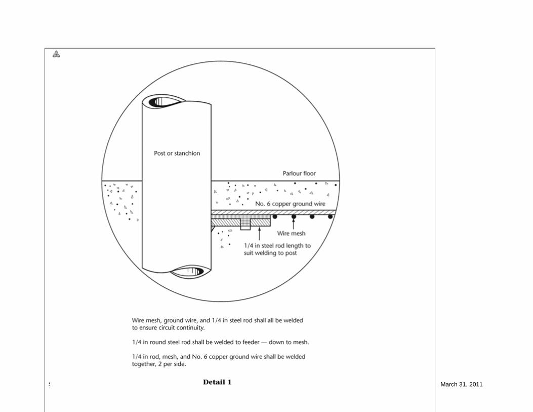
75-702 Grounding/bonding in milking areas (1) Livestock waterers, wire mesh, grates, metallic water pipes, stanchions, water bowls, vacuum lines, grain feeders, gates, support posts, and other metals shall be bonded together by a separate stranded copper conductor not smaller than No. 6 AWG. (2) The metallic equipment bonded in Subrule (1) shall be grounded and connected to the system neutral ground at the distribution panel by a separate single-stranded copper conductor not smaller than No. 6 AWG. (3) In milking parlours, concrete floors shall have a No. 9 gauge wire mesh, dimensions 15 × 15 cm (6 × 6 in), and bonding and grounding shall comply with Subrules (1) and (2). SEE DETAILED CODE PROPOSAL
Services 75-900 75-504 75-900 and 75-902 Service box installation
Section 75 Complete Document with Links Page 24 of 59 March 31, 2011
(1) When metering equipment is installed outdoors, the midpoint of the meter shall be located 1750 ± 100 mm, from finished grade, in accordance with Specifications 28 and 40. (2) Where a service box is installed on a transformer pole, no equipment other than that shown in Specification 40 shall be placed on the pole, except that one temporary service may be attached in addition to the permanent service. (3) Service boxes shall not be installed on poles located on a public road. (4) The following requirements shall apply to the Central Metering System ( CMS): (a) a standard pole-mounted distribution transformer without a secondary breaker or pole-mounted switch shall be used to supply multi- building installations; (b) the method of entry of conductors into a building shall be in accordance with Rules 6-206 and 6-302; (c) each building shall have a main service box at point of entry; (d) the service equipment shall be bonded to the neutral; (e) a ground electrode shall be installed at each service box in accordance with Rule 10-700; (f) new overhead yard wiring shall be (i) neutral-supported cable with a minimum of No. 2 AWG aluminum, and when in parallel, shall comply with Rule 12-108; and (ii) notwithstanding Item (i), open wire bus shall be permitted where circuit ampacity exceeds 200 A; (g) the minimum ampacity of overhead or underground conductors feeding more than one service or building shall be based on 80% of the sum of the ratings of all service boxes supplied; (h) transformer pole hardware and metering equipment shall be in accordance with Specifications 41, 42, and 43; (i) if metering is located on other than a transformer pole, the meter socket shall be connected to the ground electrode and the system neutral in accordance with Specification 34; (j) pole-top switches shall be installed to the following requirements: (i) the switch shall be approved for the purpose; (ii) the minimum rating of a transfer switch shall be equal to or greater than 80% of the sum of all service

Section 75 Complete Document with Links Page 25 of 59 March 31, 2011
boxes supplied; (iii) the minimum clearances on the pole shall be those shown on Specification 41; (iv) underground services shall be in accordance with the requirements of Rule 6-300; and (v) pole-top transfer switches used in conjunction with Central Metering Systems shall be installed in accordance with Specification 41; (k) all equipment mounted on a pole shall be mounted on the same 1/3 continuous pole circumference leaving the remaining 2/3 of the continuous pole circumference clear for climbing purposes; or (l) CMS-type service shall not have more than four subdivisions of the service extending from one pole. SEE DETAILED CODE PROPOSALS
Pole mounted luminaires, roadway lighting systems 75-1000 75-602 75-1000 Pole-mounted luminaires (1) Where pole-mounted luminaires are installed on poles carrying the conductors of a primary line, the luminaire shall be at least 3 m below the primary conductors. (2) Where luminaires are installed on a pole, there shall be signs cautioning that high voltage is present and advising that lamp changing shall be done only by qualified persons. (3) Notwithstanding Subrule (1) where the supply authority owns the pole-mounted luminaires, the clearance requirement does not apply. (4) Where pole-mounted luminaires are controlled from more than one point by switches, each switch shall be wired and connected so that the identified ( neutral) conductor runs directly to the luminaire(s) controlled by it. (5) The identified conductor of the circuit supplying the pole-mounted luminaire shall be permitted to be connected to the neutral conductor of a feeder or subfeeder. (6) Each lighting circuit shall have adequate overcurrent protection, for example, a weatherproof in-line fuseholder assembly is acceptable for this purpose. (7) All non-current-carrying metal parts of a luminaire shall be bonded to ground in accordance with

Section 75 Complete Document with Links Page 26 of 59 March 31, 2011
Section 10.
75-604 75-1002 Roadway lighting systems (1) Roadway lighting systems shall be installed in accordance with Rule 2-024(3) and Rules 30-100 to 30-1036, except that Rule 30-1006(1) need not apply. (2) In-line fuseholders shall be acceptable to satisfy the requirements of Rules 30-1002 and 30-1008, for single luminaires fed from overhead distribution systems where a dedicated roadway lighting bus is not available. SEE DETAILED CODE PROPOSAL
Appendix B Section 75
Rule 75-216 75-144 For situations where aggressive corrosion exists, the steel pole manufacturer shall be consulted for appropriate additional below-grade corrosion protection such as polyurethane coatings or other proven methods. Where the embedded section of a steel pole is fully coated, proper grounding can be achieved by utilizing the threaded insert provided above the groundline on the pole to connect to a driven ground rod. Rule 75-234 75-162 Concrete poles are graded according to strength in alphabetical sequence and strength: with pole strength increasing in alphabetical progression. The sizes of poles in these categories are so arranged that all poles of the same class, regardless of length, will resist the same horizontal force applied 60 cm (2 ft) from the top of the pole when supported 180 cm (6 ft) from the butt. Δ Rule 75-239 75-180 Reference publication ASCE (American Society of Civil Engineers) Manual 104-2003, Recommended Practice for Fiber-Reinforced Polymer Products For Overhead Utility Line Structures, as referenced in CSA C22.3 No. 1.

Section 75 Complete Document with Links Page 27 of 59 March 31, 2011
Rule 75-702 10-406 SEE DETAILED CODE PROPOSAL
Section 75 Complete Document with Links Page 28 of 59 March 31, 2011
Section 75 Complete Document with Links Page 29 of 59 March 31, 2011

Section 75 Complete Document with Links Page 30 of 59 March 31, 2011

Section 75 Complete Document with Links Page 31 of 59 March 31, 2011
OESC Code Rule 75-000 Description of the change: Removing subrule (c)
In the previous Codes, Section 75 included several rules related to installation of electrical equipment on the farms. Majority of the requirements were redundant with requirements in other sections of the Code and were removed. The only remaining Rule in Section 75 specific to farms is Rule 75-702 grounding/bonding in milking area. The proposal is issued to delete Rule 75-702 since Rules in Section 10, Rule’s 10-402(4) and 10-406(5) provide grounding and bonding requirements for farm equipment.
Background
By deleting the Rule 75-702, it is misleading to specify that the Section 75 applies to farm buildings. Other Sections of the Code (for example: Section 12 for wiring methods, Section 18 and 22 for classified locations, Section 10 for grounding and bonding) are applicable to installation of electrical equipment in farms. Section 75 requirements for primary or secondary poles and poles equipment (not owned by supply authority) are applicable to all installations, including farms. Therefore, it is necessary to remove Subrule (c) that specifies “farm buildings or similar structures” from the Scope of Section 75.
Rationale
Code Proposal
Return to Proposed Changes
75-000 Scope (1) This Section applies to installations of primary and secondary systems, including poles and
pole mounted equipment except owned by a supply authority. (2) This section is supplementary to or amendatory of the general requirements of this Code.
(a) installations of primary and secondary lines except for lines owned by a supply authority; and Δ (b) poles and pole-mounted electrical equipment; and (c) installation of electrical equipment in farm buildings and similar structures. (2) This Section supplements or amends the general requirements of this Code.
Section 75 Complete Document with Links Page 32 of 59 March 31, 2011
OESC Code Rule 75-002 Description of the change: Revising definitions
Section 75 was added to the OESC 20th Edition/1990 as an Ontario Amendment. This edition only recognized all secondary, primary lines and transformer poles to be wood.
Background
The current OESC 24th Edition/2009 Ontario Amendment Rule 75-200 Poles recognizes other poles such as steel, concrete and fibre reinforced poles. The definition of
Rationale
classified
Rule 75-002 will have to be revised since the current description defines wood poles only.
The definition of Penta
is not the industry acronym for pentachlorophenol; PCP is the industry acronym for treatment of poles.
Code Proposal:

Section 75 Complete Document with Links Page 33 of 59 March 31, 2011
Return to Proposed Changes
75-002 Special terminology In this Section, the following definitions apply: ACSR — aluminum conductor, steel reinforced. Classified — poles graded according to strength whereby the minimum circumferential dimensions are determined so that all poles of the same class, regardless of length, will withstand the same horizontal force applied 0.6 m from the top of the pole when supported 1.8 m from the butt end in accordance with CSA O15 series for wood poles; CSA G40.21 series for steel poles; CSA A14 series for concrete poles and ASCE Manual No. 104 for fibre-reinforced polymer. CMS — Central Metering System. Distribution system — the system by which electrical power or energy is distributed to the receiving equipment and includes components such as primary line, secondary line, services, distribution transformers, distribution equipment, and other equipment of a similar nature. Free-standing pole — a pole structure and base assembly that is installed with engineering direction without the use of guys. Lines — Primary line — a distribution system operating at more than 750 V but not more than 50 000 V phase-to-phase. Secondary line — a distribution system operating at 750 V or less. Neutral-supported cable — two or three insulated conductors and a bare neutral. Open wire bus — a secondary line conductor with a weatherproof covering on the phase conductors and includes a bare neutral. PCP Penta — wood poles treated with pentachlorophenol. Δ Pole-mounted lighting systems — a system of luminaires, poles, sign luminaires, underpass illumination, cables, power supply equipment, control system, and associated materials required to provide illumination on a roadway or associated appurtenances on private premises. Power conductor— a conductor that conveys electrical power or energy and is not part of a communication circuit. Δ Roadway lighting systems — a system of luminaires, polessign luminaires, underpass illumination, cables, power supply equipment, control systems and associated materials required to provide illumination on a roadway or associated appurtenances on a Municipal or Provincial right of way.

Section 75 Complete Document with Links Page 34 of 59 March 31, 2011
OESC Code Rule 75-004 Description of the change: Removing sub rule (1)
Section 75 was added to the OESC 20th Edition/1990 as an Ontario Amendment along with Rule 75-004 General Requirements.
Background
To be consistent with all other Sections of the OESC, suggest removing sub rule (1) and renumber sub rules (2) to (5) inclusive.
Rationale
Code Proposal
Return to Proposed Changes
Δ 75-004 General requirements (1) Every installation under this Section shall be inspected in accordance with Section 2 of this Code. (2)(1) Where the work consists of the installation of a service, the contractor shall consult the supply authority as to the layout of the service and the location of the transformer and meter, regarding compliance with applicable codes or standards under a rule or by-law of the supply authority. (3)(2) Where the work consists of the installation of conductors over or under a railway, the contractor shall submit to the inspection department a plan of the crossing endorsed by the railway company with an approval of the work. (4)(3) Where approval is required from the supply authority by this Rule, such approval shall be obtained prior to commencement of any work with respect to the installation. (5)(4) Where a consumer desires to install the conductors of a primary or secondary line across a public road, the crossing shall not be made without written permission from both the supply authority and the authority having jurisdiction over the road and shall have the minimum clearance as specified in Rule 75-310(1) 75-706(1).

Section 75 Complete Document with Links Page 35 of 59 March 31, 2011
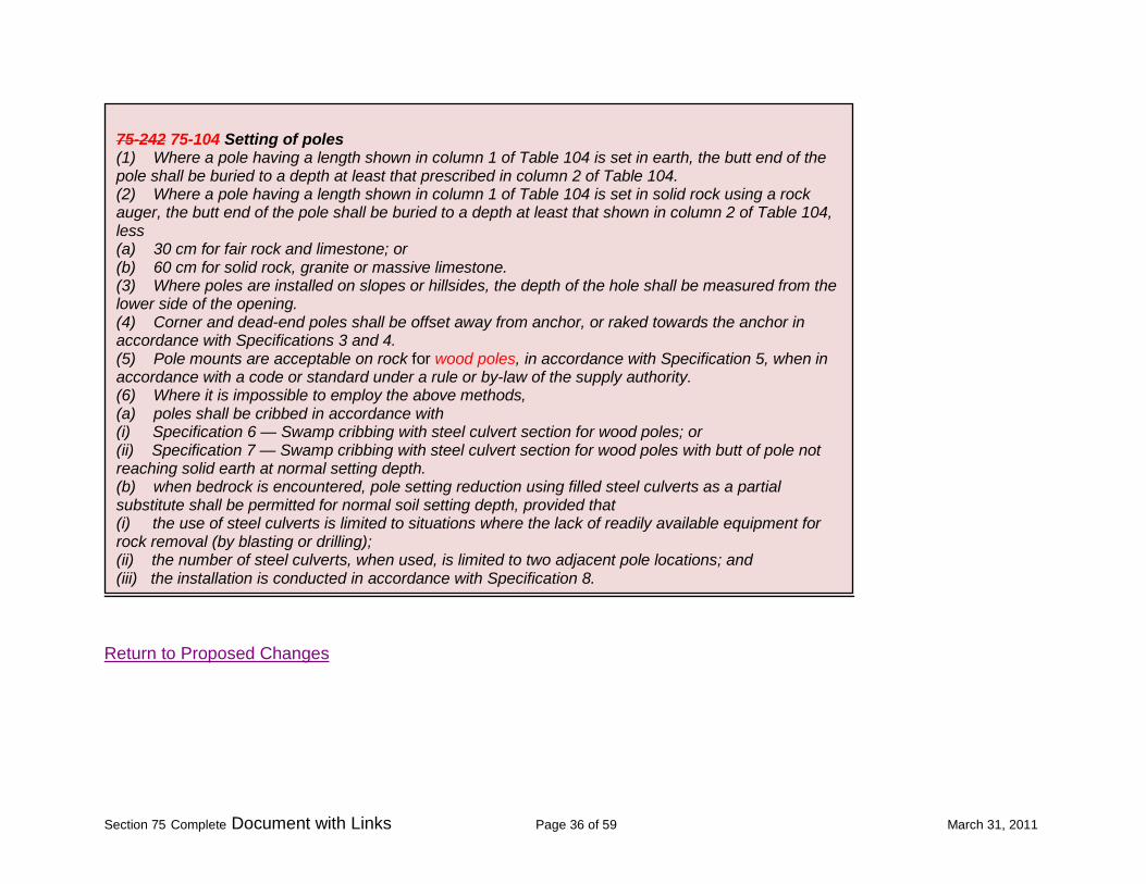
OESC Code Rule 75-242 75-104 Description of the change: re-number rule and revising sub- rule (5) to include wood pole
Current Rule 75-242 Setting of Poles was previously added to the OESC 20th Edition/1990 Ontario Amendment.
Background
Pole mounts are only available for wood poles only and are not acceptable for use on steel, concrete and fibre reinforced polymer poles. Specification 5 detail shows a wood pole.
Rationale
Code Proposal:
Section 75 Complete Document with Links Page 36 of 59 March 31, 2011
Return to Proposed Changes
75-242 75-104 Setting of poles (1) Where a pole having a length shown in column 1 of Table 104 is set in earth, the butt end of the pole shall be buried to a depth at least that prescribed in column 2 of Table 104. (2) Where a pole having a length shown in column 1 of Table 104 is set in solid rock using a rock auger, the butt end of the pole shall be buried to a depth at least that shown in column 2 of Table 104, less (a) 30 cm for fair rock and limestone; or (b) 60 cm for solid rock, granite or massive limestone. (3) Where poles are installed on slopes or hillsides, the depth of the hole shall be measured from the lower side of the opening. (4) Corner and dead-end poles shall be offset away from anchor, or raked towards the anchor in accordance with Specifications 3 and 4. (5) Pole mounts are acceptable on rock for wood poles, in accordance with Specification 5, when in accordance with a code or standard under a rule or by-law of the supply authority. (6) Where it is impossible to employ the above methods, (a) poles shall be cribbed in accordance with (i) Specification 6 — Swamp cribbing with steel culvert section for wood poles; or (ii) Specification 7 — Swamp cribbing with steel culvert section for wood poles with butt of pole not reaching solid earth at normal setting depth. (b) when bedrock is encountered, pole setting reduction using filled steel culverts as a partial substitute shall be permitted for normal soil setting depth, provided that (i) the use of steel culverts is limited to situations where the lack of readily available equipment for rock removal (by blasting or drilling); (ii) the number of steel culverts, when used, is limited to two adjacent pole locations; and (iii) the installation is conducted in accordance with Specification 8.

Section 75 Complete Document with Links Page 37 of 59 March 31, 2011
OESC Code Table 104 Description of the change: revise rules on table
Table 104 was added as an Ontario Amendment in the OESC 20th Edition/1990.
Background
Rationale
Updating of Table 104 is required since the reference to Appendix B no longer exists. Column 3 in Table 104 only refers to wood poles (CAN/CSA-015) only. Steel, concrete and fibre reinforced polymer pole current standards do not indicate height of marking of poles.
Code Proposal
Return to Proposed Changes
Table 104
Depth of setting of poles in soil (See Rules 75-208, 75-220, 75-224, 75-236, 75-238, 75-239 and 75-242 and Appendix B.)
75-104, 75-122, 75-146, 75-144, 75-164, 75-166 and 75-180

Section 75 Complete Document with Links Page 38 of 59 March 31, 2011
OESC Code Rule 75-210 Description of the change: remove all of rule entirely
Rule 75-210 Steel Poles Set Directly in Soil was added in the OESC 22nd Edition/1998 as an Ontario Amendment recognizing the use of steel poles in the industry.
Background
Removed the requirement to install steel poles in accordance with the subsequent rules; this will be consistent with the other sections of the OESC.
Rationale
Code Proposal
Return to Proposed Changes
75-210 Steel poles set directly in soil Steel poles set directly in soil are acceptable subject to compliance with Rules 75-212 through 75-224

Section 75 Complete Document with Links Page 39 of 59 March 31, 2011
OESC Code Rule 75-228 75-160 Description of the change: re-number rule and revising rule to include standard
Rule 75-228 Concrete poles was added in the OESC 22nd Edition/1998 as an Ontario Amendment recognizing the use of concrete poles in the industry.
Background
Removed the requirement to install concrete poles in accordance with the subsequent rules; this will be consistent with the other sections of the OESC. Adding the sub-rule to include the requirement for the reinforcing metal of the pole to have provision for grounding as per accordance with CAN/CSA A14 will ensure the concrete poles will meet the requirements of the OESC.
Rationale
Code Proposal
Return to Proposed Changes
75-228 75-160 Concrete poles Installations of concrete poles shall be in accordance with Rules 75-232 through 75-238.
1. Concrete pole shall be manufactured in accordance with CAN/CSA A14-Concrete Poles; and 2. Concrete poles shall have provision for grounding of the reinforcing metal of the pole.

Section 75 Complete Document with Links Page 40 of 59 March 31, 2011
OESC Code Rule 75-234 75-162 Description of the change: added reference to Appendix
Rule 75-234 Concrete pole selection was added in the OESC 22nd Edition/1998 as an Ontario Amendment recognizing the use of concrete poles in the industry.
Background
Added reference to Appendix B for the rule; existing Appendix B did refer to this rule. Rationale
Code Proposal
Return to Proposed Changes
75-234 75-162 Concrete pole selection (see Appendix B) (1) Accepted pole classes shall be in accordance with the equivalencies in Table 101. Δ (2) Notwithstanding Rule 75-200 75-100, a used concrete pole may be used on secondary lines only after its condition has been checked by the inspection department and before the pole is set in the ground.

Section 75 Complete Document with Links Page 41 of 59 March 31, 2011
OESC Code Rule 75-244 75-200 Description of the change: Re-name and re-number rule and deletion of sub-rules (1) & (2).
Section 75 was added to the OESC 20th Edition/1990 as an Ontario Amendment. Current Rule 75-244 provides requirements for pole spans and pole framing.
Background
Existing sub-rule’s (1) & (2) relocated to the proposed new Rule 75-600 Spans and Sags. The remaining of Rule 75-244 is re-named to clarify that the requirements are applicable to pole framing and is re-numbered as Rule 75-200.
Rationale
Code Proposal
Return to Proposed Changes
75-244 75-200 Pole spans and framing Pole Framing (1) Poles used in secondary lines shall be placed not more than 40 m apart. (2) Subject to Subrule (3), poles used in primary lines shall be placed not more than 90 m apart. (3) Poles used in primary lines shall be framed according to the following Specifications: Specification 9 — Primary, 1-phase, 2.4 to 8 kV, maximum span 90 m. Specification 10 — Primary, 1-phase, 2.4 to 16 kV, maximum span 90 m. Specification 11 — Primary, 3-phase, 2.4/4.16 to 8.0/13.8 kV. Specification 12 — Primary, 3-phase, 2.4/4.16 to 16/27.6 kV. Specification 13 — Primary, 3-phase, line angles 4°–90°, 2.4/4.16 to 16/27.6 kV. Specification 14 — Primary, 3-phase, crossarm, 2.4/4.16 to 16/27.6 kV. Specification 15 — Primary, 3-phase, underbuilt, 2.4/4.16 to 16/27.6 kV. Specification 16 — Primary, 3-phase, 44 kV. Specification 17 — Primary, 3-phase, line angles 4°–90°, 44 kV. Specification 18 — Primary, 3-phase, crossarm, 44 kV.
Section 75 Complete Document with Links Page 42 of 59 March 31, 2011
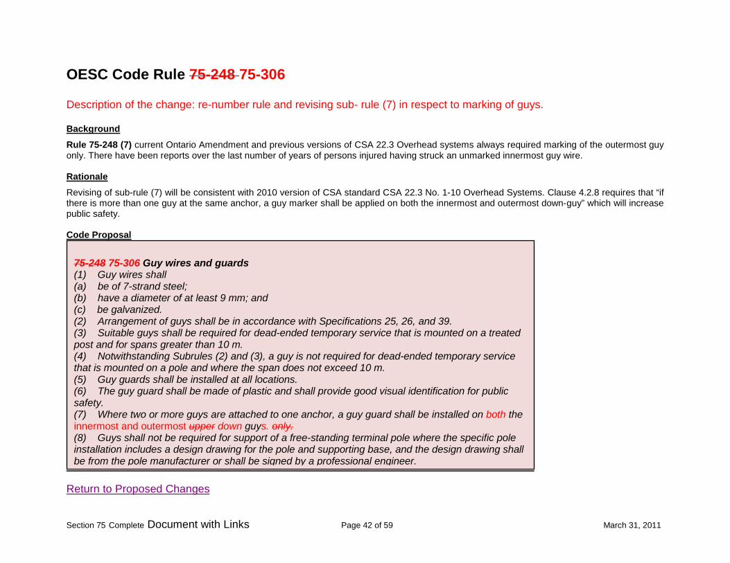
OESC Code Rule 75-248 75-306 Description of the change: re-number rule and revising sub- rule (7) in respect to marking of guys.
Rule 75-248 (7) current Ontario Amendment and previous versions of CSA 22.3 Overhead systems always required marking of the outermost guy only. There have been reports over the last number of years of persons injured having struck an unmarked innermost guy wire.
Background
Revising of sub-rule (7) will be consistent with 2010 version of CSA standard CSA 22.3 No. 1-10 Overhead Systems. Clause 4.2.8 requires that “if there is more than one guy at the same anchor, a guy marker shall be applied on both the innermost and outermost down-guy” which will increase public safety.
Rationale
Code Proposal
Return to Proposed Changes
75-248 75-306 Guy wires and guards (1) Guy wires shall (a) be of 7-strand steel; (b) have a diameter of at least 9 mm; and (c) be galvanized. (2) Arrangement of guys shall be in accordance with Specifications 25, 26, and 39. (3) Suitable guys shall be required for dead-ended temporary service that is mounted on a treated post and for spans greater than 10 m. (4) Notwithstanding Subrules (2) and (3), a guy is not required for dead-ended temporary service that is mounted on a pole and where the span does not exceed 10 m. (5) Guy guards shall be installed at all locations. (6) The guy guard shall be made of plastic and shall provide good visual identification for public safety. (7) Where two or more guys are attached to one anchor, a guy guard shall be installed on both the innermost and outermost upper down guys. only. (8) Guys shall not be required for support of a free-standing terminal pole where the specific pole installation includes a design drawing for the pole and supporting base, and the design drawing shall be from the pole manufacturer or shall be signed by a professional engineer.

Section 75 Complete Document with Links Page 43 of 59 March 31, 2011
OESC Code Rule 75-214 75-314 Description of the change: re-number rule and deletion of sub-rules (6) and (8).
Pole mounts and swamp cribbing are used for wood pole installation only.
Background
Removal of sub-rule (6) is no longer valid as this rule is required for the use of wood poles not steel poles.
Rationale
Removal of sub-rule (8) will be consistent with Rule 75-242(5) Rule 75-104(5).
Code Proposal
Return to Proposed Changes
75-214 75-314 Guying of steel poles Δ (1) Notwithstanding Rule 75-250 75-310, guys directly attached to steel poles need not have a guy insulator, and the attachment hardware shall be suitable for the poles. (2) The number and placing of guys, in addition to meeting the requirements of this Code shall be in accordance with the manufacturer’s recommendations. (3) The baseplate and top cap recommended by the manufacturer for the poles shall be installed. (4) Clamps for the neutral conductor shall be a type designed for the poles. (5) Spool-type insulating supports shall not be permitted. (6) A bolt to guard against pole splitting at the top shall not be required. (6)(7) The distance from top of the pole down to the top bolt for pole line hardware shall be permitted to be 10 cm rather than the 15 or 20 cm used for wood poles. (8) Pole mounts for rock shall not be permitted. (7) (9) Swamp cribbing shall be permitted to be used only where permitted by and in accordance with the manufacturers’ instructions.

Section 75 Complete Document with Links Page 44 of 59 March 31, 2011
OESC Code Rule 75-316 75-500 Description of the change: Re-name and re-number rule.
Rule 75-316 is an Ontario Amendment added to the OESC 20th Edition/1990.
Background
Editorial change of the rule’s heading to clarify the intent of the rule.
Rationale
Code Proposal
Return to Proposed Changes
75-316 75-500 Overhead primary line conductors Primary line conductors shall be bare and not less than No. 2 AWG ACSR.

Section 75 Complete Document with Links Page 45 of 59 March 31, 2011
OESC Code Rule 75-606 75-502 Description of the change: Re-name and re-number rule.
Rule 75-606 Aerially supported cables is a Ontario Amendment added to the OESC 24th Edition/2009. The amendment was added to recognize acceptable practices and recognition of NS75 and NS 90 types of neutral supported cables in Tables 36A and 36B.
Background
The current rule heading is revised to clarify the intent of the rule.
Rationale
The addition of RWU type cables to be used for aerial installations are recognized and accepted by manufacturers as stated in the accompanying OESC Bulletin #2-12-9. Existing sub-rule (2) revised as an editorial change; was shown incorrectly as Table 10.
Code Proposal
Δ 75-606 75-502 Aerially supported cables Overhead secondary line conductors
(1) Overhead cables shall be a) neutral-supported cables of Type NS75 or Type NS90 or b) Open wire buss
(2) Individual conductors of the moisture- resistant, rubber- insulated type suitable for exposed wiring where exposed to the weather as specified in Table 19 10 and cabled lashed together with a messenger cable, shall be (a) stranded; and (b) not less than No. 12 AWG copper or No. 10 AWG aluminum (3) RWU type cables are acceptable for aerial installation and can be lashed together with a messenger cable.

Section 75 Complete Document with Links Page 46 of 59 March 31, 2011
Ontario Electrical Safety Code –Bulletin 2-12-*
(3) Aerially supported cable
Cables and conductors shall be of types suitable for exposure to the weather as listed in Table 19 and approved for this
type of installation. Additionally, cables and conductors shall be marked for sunlight resistance (“SR” or “SUNLIGHT RESISTANCE”) where installed and used subject to direct rays of sun, as per Rule 2-130.
For example, Rule 30-1102 permits Types RW75, R90, RW90, TW, TWU, TW75, and TWU75 conductors to be lashed to a messenger cable for outdoor lighting where exposed to the weather. Type RWU
conductors shall also be permitted, although not listed in Table 19.
Rationale The cable manufacturers have indicated that Type RWU cables will withstand the effects of ultra violet light and exposure to the weather (when marked as such)
and the lashing will not have an injurious effect on the insulation.
Return to Proposed Changes
Section 75 Complete Document with Links Page 47 of 59 March 31, 2011
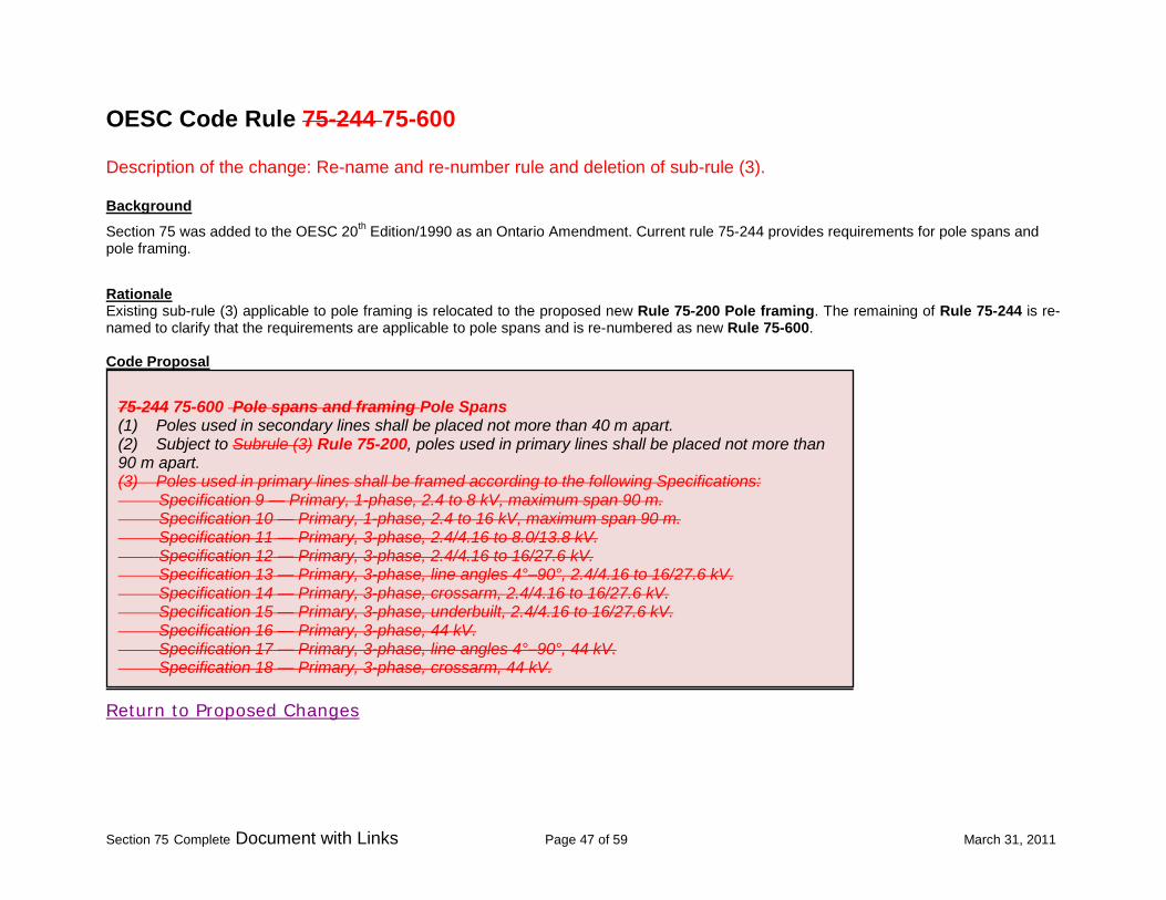
OESC Code Rule 75-244 75-600 Description of the change: Re-name and re-number rule and deletion of sub-rule (3).
Section 75 was added to the OESC 20th Edition/1990 as an Ontario Amendment. Current rule 75-244 provides requirements for pole spans and pole framing.
Background
Existing sub-rule (3) applicable to pole framing is relocated to the proposed new Rule 75-200 Pole framing. The remaining of Rule 75-244 is re-named to clarify that the requirements are applicable to pole spans and is re-numbered as new Rule 75-600.
Rationale
Code Proposal
Return to Proposed Changes
75-244 75-600 Pole spans and framing Pole Spans (1) Poles used in secondary lines shall be placed not more than 40 m apart. (2) Subject to Subrule (3) Rule 75-200, poles used in primary lines shall be placed not more than 90 m apart. (3) Poles used in primary lines shall be framed according to the following Specifications: Specification 9 — Primary, 1-phase, 2.4 to 8 kV, maximum span 90 m. Specification 10 — Primary, 1-phase, 2.4 to 16 kV, maximum span 90 m. Specification 11 — Primary, 3-phase, 2.4/4.16 to 8.0/13.8 kV. Specification 12 — Primary, 3-phase, 2.4/4.16 to 16/27.6 kV. Specification 13 — Primary, 3-phase, line angles 4°–90°, 2.4/4.16 to 16/27.6 kV. Specification 14 — Primary, 3-phase, crossarm, 2.4/4.16 to 16/27.6 kV. Specification 15 — Primary, 3-phase, underbuilt, 2.4/4.16 to 16/27.6 kV. Specification 16 — Primary, 3-phase, 44 kV. Specification 17 — Primary, 3-phase, line angles 4°–90°, 44 kV. Specification 18 — Primary, 3-phase, crossarm, 44 kV.

Section 75 Complete Document with Links Page 48 of 59 March 31, 2011
OESC Code Rule 75-310 75-706 Description of the change: re-number rule and addition of sub- rule (5).
Current Rule 75-310 Primary and secondary lines clearances were added to the OESC 20th Edition/1990 Ontario Amendment.
Background
Revision of minimum vertical clearance required to align with Table 34.
Rationale
Sub-rule (5) added to recognize the standard design which many utilities as well as the Ministry of Transportation Ontario design and install their systems in compliance with CSA C22.3 No. 1-06, Overhead systems on public right of ways. This is an acceptable and recognized practice
Code Proposal
Return to Proposed Changes
75-310 75-706 Primary and secondary lines clearances (1) The poles that support the phase conductor of a primary line shall be so located and of such height as to afford a clearance of 7 m measured vertically between the conductors under maximum sag conditions and the ground. (2) Notwithstanding Subrule (1) for high voltage line installations where plans are submitted for examination to the inspection department, the clearances listed in Table 34 are acceptable. (3) The primary line neutral shall be considered a secondary conductor and shall have the same minimum vertical clearance as specified in Subrule (4). Δ (4) Conductors of a secondary line shall have a minimum 6.1 m measured vertically between the conductors under maximum sag conditions and the ground. (5) Notwithstanding Subrule (1) for high and low voltage line installations on public right of ways, for the purpose of roadway lighting systems or traffic control systems, CSA 22.3 No.1-06, Overhead systems or the Ontario Provincial Standards shall be permitted.
Section 75 Complete Document with Links Page 49 of 59 March 31, 2011
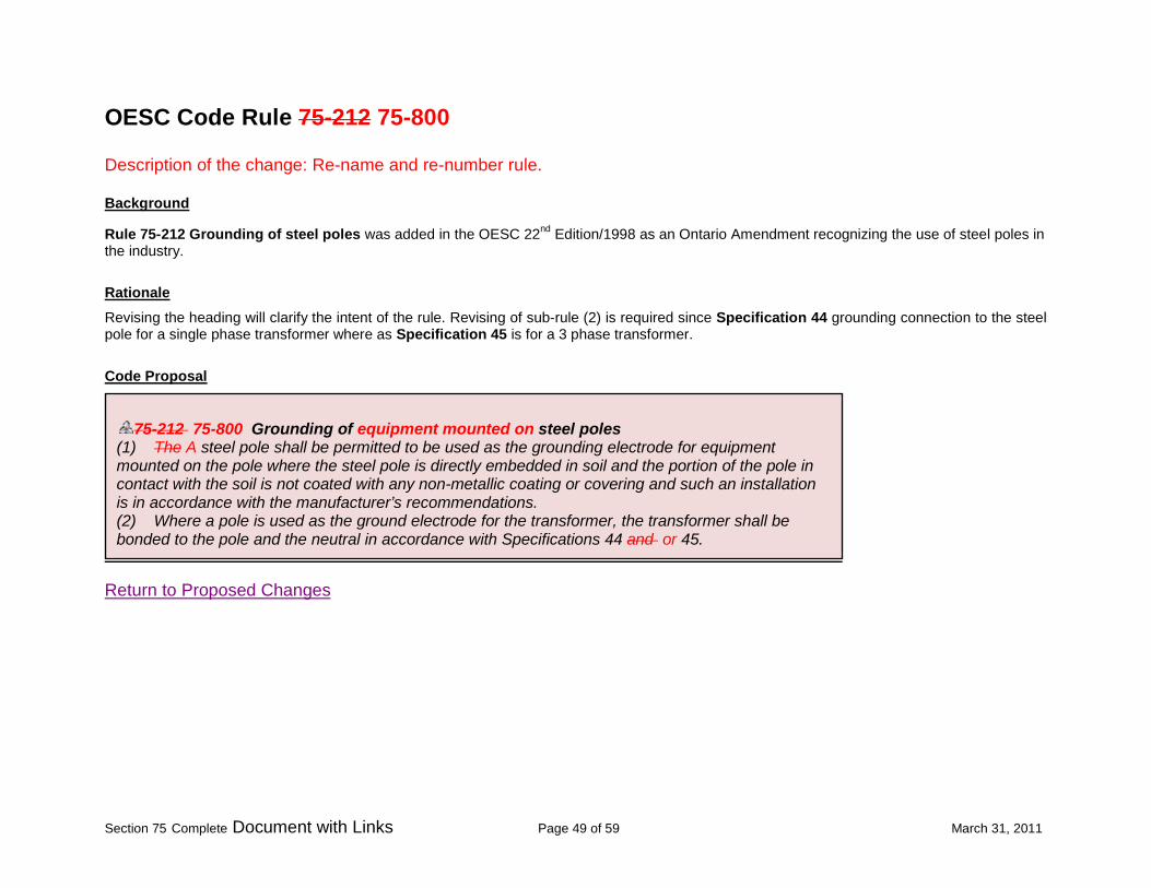
OESC Code Rule 75-212 75-800 Description of the change: Re-name and re-number rule.
Rule 75-212 Grounding of steel poles was added in the OESC 22nd Edition/1998 as an Ontario Amendment recognizing the use of steel poles in the industry.
Background
Revising the heading will clarify the intent of the rule. Revising of sub-rule (2) is required since Specification 44 grounding connection to the steel pole for a single phase transformer where as Specification 45 is for a 3 phase transformer.
Rationale
Code Proposal
Return to Proposed Changes
75-212 75-800 Grounding of equipment mounted on steel poles
(1) The A steel pole shall be permitted to be used as the grounding electrode for equipment mounted on the pole where the steel pole is directly embedded in soil and the portion of the pole in contact with the soil is not coated with any non-metallic coating or covering and such an installation is in accordance with the manufacturer’s recommendations. (2) Where a pole is used as the ground electrode for the transformer, the transformer shall be bonded to the pole and the neutral in accordance with Specifications 44 and or 45.

Section 75 Complete Document with Links Page 50 of 59 March 31, 2011
OESC Code Rule 75-232 75-802 Description of the change: re-number rule and editorial change.
Rule 75-232 Grounding of concrete poles was added in the OESC 22nd Edition/1998 as an Ontario Amendment recognizing the use of concrete poles in the industry.
Background
Editorial change to clarify the intent of the rule.
Rationale
Code Proposal
Return to Proposed Changes
75-232 75-802 Grounding of concrete poles
(1) Each pole shall be installed with a grounding stud and The grounding stud of each pole shall be connected to the system neutral or ground rod electrode to provide grounding for the reinforcing bars. (2) The reinforcing bars shall not be considered as a ground electrode

Section 75 Complete Document with Links Page 51 of 59 March 31, 2011
OESC Code Rule 75-402 75-804 Description of the change: Re-name and re-number rule.
Section 75 was added to the OESC 20th Edition/1990 as an Ontario Amendment. Current Rule 75-402 provides requirements for Grounding of steel crossarms.
Background
Revised the heading to clarify the intent of the rule.
Rationale
Code Proposal
Return To Proposed Changes
75-402 75-804 Grounding of steel cCrossarms
Where porcelain dead-end insulators are used, steel crossarms shall be connected to a ground electrode with a conductor of not less than (a) No. 4 AWG stranded bare copper conductor for 27.6 kV and below; and (b) No. 1/0 AWG stranded bare copper conductor for voltages greater than 27.6 kV

Section 75 Complete Document with Links Page 52 of 59 March 31, 2011
OESC Code Rule 75-408 75-810 Description of the change: Re-name and re-number rule.
Current Rule 75-408 was added to the OESC 22nd Edition/1998 as an Ontario Amendment.
Background
Editorial change of the title.
Rationale
Code Proposal
Return to Proposed Changes
75-408 75-810 Grounding the a service box on a transformer pole (1) Where a service box is installed on a transformer pole and the supply authority owns the transformation, (a) the pole-top equipment/ system ground conductor and ground electrode shall be installed at the pole by the supply authority; (b) the contractor shall install a grounding conductor, connect one end to the identified neutral conductor in the service box, bond it to the non-current carrying metal parts of the electrical equipment, and extend at least 500 mm of the ground conductor outside of the service equipment for connection to the supply authority ground conductor; and (c) the supply authority shall connect the service ground conductor to the supply authority ground wire. (2) The neutral conductor shall be installed and connected in the service box. (3) The neutral conductor shall be installed with both the line and the load conductors on the service pole. (4) Where the transformation is privately owned, the owner shall supply and install all grounding and bonding

Section 75 Complete Document with Links Page 53 of 59 March 31, 2011
OESC Code Rule 75-702 Description of the change: remove rule entirely
Background
Rule 75-702 Grounding/bonding in milking areas is the only Rule in “Farm buildings” sub-sectionof section 75. In the previous Codes, Section 75 included several rules related to installation of electrical equipment on the farms. Majority of the requirements were redundant with requirements in other sections of the Code and were removed. Rationale This rule deals with the grounding/bonding in milking areas and is no longer required since the grounding and bonding requirements are addressed in Section 10 Grounding and Bonding as Rule’s 10-402(4) and 10-406(5). Rule 10-406(5) is specific to buildings housing live stock and provide the same requirements as existing Subrule 75-702(1). The existing Appendix B diagrams associated with this rule will be retained as a bulletin in Section 10. Furthermore a code proposal will also be submitted. 10-402 Fixed equipment, specific (4) Electrical equipment, such as livestock waterers, installed in feedlots and open feeding areas shall be bonded to ground by a separate stranded copper bonding conductor not less than No. 6 AWG terminating at a point where the branch circuit receives its supply. 10-406 Non-electrical equipment (see Appendix B) (5) In buildings housing livestock, all metal water pipes, stanchions, water bowls, vacuum lines, and other metals that could become energized shall be bonded to ground by a separate stranded copper bonding conductor not smaller than No. 6 AWG except that, where it is necessary to control the effects of stray earth current, a device specifically approved for the purpose, connected in series with the bonding conductor, shall be permitted.

Section 75 Complete Document with Links Page 54 of 59 March 31, 2011
Code Proposal
Return to Proposed Changes
75-702 Grounding/bonding in milking areas
(1) Livestock waterers, wire mesh, grates, metallic water pipes, stanchions, water bowls, vacuum lines, grain feeders, gates, support posts, and other metals shall be bonded together by a separate stranded copper conductor not smaller than No. 6 AWG. (2) The metallic equipment bonded in Subrule (1) shall be grounded and connected to the system neutral ground at the distribution panel by a separate single-stranded copper conductor not smaller than No. 6 AWG. (3) In milking parlours, concrete floors shall have a No. 9 gauge wire mesh, dimensions 15 × 15 cm (6 × 6 in), and bonding and grounding shall comply with Subrules (1) and (2).

Section 75 Complete Document with Links Page 55 of 59 March 31, 2011
OESC Code Rule 75-504 75-900 Description of the change: re-number rule and delete sub-rule (4)
Background Section 75 was added to the OESC 20th Edition/1990 as an Ontario Amendment. Current rule 75-504 provides requirements for service box installation and Central Metering System (CMS) installations. Rationale Existing sub-rule (4) applicable to Central Metering System (CMS) installations is relocated to the proposed new Rule 75-902 Central Metering Systems. The remaining of Rule 75-504 is re-numbered as new Rule 75-900. Sub-rule (2) revised to the correct Specification. Code Proposal

Section 75 Complete Document with Links Page 56 of 59 March 31, 2011
Δ 75-504 75-900 Service box installation (1) When metering equipment is installed outdoors, the midpoint of the meter shall be located 1750 ± 100 mm, from finished grade, in accordance with Specifications 28 and 40. (2) Where a service box is installed on a transformer pole, no equipment other than that shown in Specification 40 41 shall be placed on the pole, except that one temporary service may be attached in addition to the permanent service. (3) Service boxes shall not be installed on poles located on a public road. (4) The following requirements shall apply to the Central Metering System ( CMS): (a) a standard pole-mounted distribution transformer without a secondary breaker or pole-mounted switch shall be used to supply multi- building installations; (b) the method of entry of conductors into a building shall be in accordance with Rules 6-206 and 6-302; (c) each building shall have a main service box at point of entry; (d) the service equipment shall be bonded to the neutral; (e) a ground electrode shall be installed at each service box in accordance with Rule 10-700; (f) new overhead yard wiring shall be (i) neutral-supported cable with a minimum of No. 2 AWG aluminum, and when in parallel, shall comply with Rule 12-108; and (ii) notwithstanding Item (i), open wire bus shall be permitted where circuit ampacity exceeds 200 A; (g) the minimum ampacity of overhead or underground conductors feeding more than one service or building shall be based on 80% of the sum of the ratings of all service boxes supplied; (h) transformer pole hardware and metering equipment shall be in accordance with Specifications 41, 42, and 43; (i) if metering is located on other than a transformer pole, the meter socket shall be connected to the ground electrode and the system neutral in accordance with Specification 34; (j) pole-top switches shall be installed to the following requirements: (i) the switch shall be approved for the purpose; (ii) the minimum rating of a transfer switch shall be equal to or greater than 80% of the sum of all service boxes supplied; (iii) the minimum clearances on the pole shall be those shown on Specification 41; (iv) underground services shall be in accordance with the requirements of Rule 6-300; and (v) pole-top transfer switches used in conjunction with Central Metering Systems shall be installed in accordance with Specification 41; (k) all equipment mounted on a pole shall be mounted on the same 1/3 continuous pole circumference leaving the remaining 2/3 of the continuous pole circumference clear for climbing purposes; or (l) CMS-type service shall not have more than four subdivisions of the service extending from one pole.
Section 75 Complete Document with Links Page 57 of 59 March 31, 2011
OESC Code Rule 75-504 75-902 Description of the change: Re-name and re-number rule and delete sub-rules (1), (2) and (3)
Background Section 75 was added to the OESC 20th Edition/1990 as an Ontario Amendment. Current rule 75-504 provides requirements for service box installation and Central Metering System (CMS) installations. Rationale Existing sub-rules (1), (2) and (3) relocated to the proposed new Rule 75-900 Service Box Installation. The remaining of Rule 75-504 is re-numbered as Rule 75-902. Code Proposal

Section 75 Complete Document with Links Page 58 of 59 March 31, 2011
Return to Proposed Changes
Δ 75-504 75-902 Service box installation Central Metering System (CMS): (1) When metering equipment is installed outdoors, the midpoint of the meter shall be located 1750 ± 100 mm, from finished grade, in accordance with Specifications 28 and 40. (2) Where a service box is installed on a transformer pole, no equipment other than that shown in Specification 40 shall be placed on the pole, except that one temporary service may be attached in addition to the permanent service. (3) Service boxes shall not be installed on poles located on a public road. (4) (1) The following requirements shall apply to the Central Metering System ( CMS): (a) a standard pole-mounted distribution transformer without a secondary breaker or pole-mounted switch shall be used to supply multi- building installations; (b) the method of entry of conductors into a building shall be in accordance with Rules 6-206 and 6-302; (c) each building shall have a main service box at point of entry; (d) the service equipment shall be bonded to the neutral; (e) a ground electrode shall be installed at each service box in accordance with Rule 10-700; (f) new overhead yard wiring shall be (i) neutral-supported cable with a minimum of No. 2 AWG aluminum, and when in parallel, shall comply with Rule 12-108; and (ii) notwithstanding Item (i), open wire bus shall be permitted where circuit ampacity exceeds 200 A; (g) the minimum ampacity of overhead or underground conductors feeding more than one service or building shall be based on 80% of the sum of the ratings of all service boxes supplied; (h) transformer pole hardware and metering equipment shall be in accordance with Specifications 41, 42, and 43; (i) if metering is located on other than a transformer pole, the meter socket shall be connected to the ground electrode and the system neutral in accordance with Specification 34; (j) pole-top switches shall be installed to the following requirements: (i) the switch shall be approved for the purpose; (ii) the minimum rating of a transfer switch shall be equal to or greater than 80% of the sum of all service boxes supplied; (iii) the minimum clearances on the pole shall be those shown on Specification 41; (iv) underground services shall be in accordance with the requirements of Rule 6-300; and (v) pole-top transfer switches used in conjunction with Central Metering Systems shall be installed in accordance with Specification 41; (k) all equipment mounted on a pole shall be mounted on the same 1/3 continuous pole circumference leaving the remaining 2/3 of the continuous pole circumference clear for climbing purposes; or (l) CMS-type service shall not have more than four subdivisions of the service extending from one pole.

Section 75 Complete Document with Links Page 59 of 59 March 31, 2011
OESC Code Rule 75-604 75-1002 Description of the change: re-number rule and revision of sub-rule (1)
Background
Current rule was added to the OESC 24th Edition/2009 as an Ontario Amendment to recognize roadway lighting systems on public right of ways. Rationale Existing sub-rule (1) revised as an editorial change; was shown incorrectly as 30-100.This was highlighted on Bulletin 0-3-4 Errors and omissions in 2009 Ontario Electrical Safety Code. Code Proposal
Return to Proposed Changes
75-604 Roadway lighting systems (1) Roadway lighting systems shall be installed in accordance with Rule 2-024(3) and Rules 30-1000 to 30-1036, except that Rule 30-1006(1) need not apply. (2) In-line fuseholders shall be acceptable to satisfy the requirements of Rules 30-1002 and 30-1008, for single luminaires fed from overhead distribution systems where a dedicated roadway lighting bus is not available.


![[ Indoor ] - toki.co.jp · 5/6 SPECIFICATION PRODUCT CODE WIRING MOUNTING POSITION MOUNTING PROCEDURES GRHB-75-3000K-SP Spacing Color Temperature Beam Angle 60 75 100 60mm 75mm 100mm](https://img.pdfslide.us/doc/110x75/5f07c1d27e708231d41e96db/-indoor-tokicojp-56-specification-product-code-wiring-mounting-position.jpg)


![6. Wiring Diagram - weidefamily.net coil Transmission control module ... WIRING DIAGRAM 6. Wiring Diagram. MEMO: 21 WIRING DIAGRAM ... 76 6-3 [D6R2] WIRING DIAGRAM 6](https://img.pdfslide.us/doc/110x75/5aa0cc3b7f8b9a62178ea5e7/6-wiring-diagram-coil-transmission-control-module-wiring-diagram-6-wiring.jpg)