Embed Size (px)
Citation preview

LATEST REVISION: JANUARY 1, 2018 7-1
SECTION 7
7.0 DRAINAGE SECTION 7.1 GENERAL
This section provides stormwater design information for local agencies, engineers, developers, or others whose activities affect stormwater management within the City jurisdictional area. The section will serve as a guide for City Staff, consultants, and citizens to achieve consistency in the design and compliance of stormwater drainage components of projects so that both growth and environmental guidelines can be followed effectively. This section has been prepared to address the following main topics:
x Hydrologic determination of stormwater runoff peak flow and volume; x Hydraulic design of stormwater conveyance systems; x Hydraulic design of stormwater storage systems; and x FEMA requirements.
Submittal requirements are discussed in this Manual in Section 1.3.4 “Development Review Team (DRT)”.
7.1.1 City Stormwater Management Manual
The drainage section shall be used in conjunction with the April 2003 City Stormwater Management Manual (SWMM) prepared by CH2M Hill. The SWMM contains methodology, theory, nomographs, figures, and example problems that can be used as guidance to meet design requirements contained in this section. If there are any conflicts between the SWMM and this Manual, this Manual will prevail.
7.1.2 Policy and Criteria
Theoretical information contained in this section is generally presented in basic context and assumes the user has some technical training related to drainage and stormwater management. This section is not intended to function as a “stand-alone” reference and the user is encouraged to utilize additional resources such as the SWMM and hydrologic and hydraulic references.
The user is responsible for following the policies, criteria, procedures, and practices identified in this section and the City’s other appropriate Manuals, ordinances, and regulations relevant to drainage design. The user shall utilize his or her knowledge and judgment to hold paramount the safety, health, and welfare of the public.
7.1.3 Environmental Considerations
The increasing focus on nonpoint source pollution and stormwater quality with the amendment of the Clean Water Act in 1987 and subsequent legislation require Alabama communities to address urban stormwater runoff water quality. Numerous federal and

LATEST REVISION: JANUARY 1, 2018 7-2
7. DRAINAGE SECTION
state requirements define what is required of local governments in terms of their local stormwater management programs and related community planning and development efforts.
The Water Resource Management Department is responsible for managing the water, wastewater, and stormwater quality for the City. As such, the Water Resources Management Department has adopted the Water Resource Management Design and Construction Manual (WRM Manual) as the primary guide for development that will receive City and Water Works Board of the City (AWWB) services that fall under the responsibility of the Water Resources Management Department. The WRM Manual contains requirements and criteria for design of erosion and sediment control and post- development stormwater quality best management practices and controls as well as submittal requirements for water quality related stormwater controls. Inspection, operation and maintenance requirements for each stormwater control are also contained in the WRM Manual.
7.1.4 Computer Models
Hydrologic and hydraulic computer models can be utilized for stormwater design and shall use the appropriate methodology as outlined in this Manual.
LATEST REVISION: JANUARY 1, 2018 7-3
7. DRAINAGE SECTION
7.2 STORMWATER HYDROLOGY
The key hydrologic component in design of stormwater conveyance and storage systems is the determination of the volume, time distribution and rate of stormwater runoff for various frequency recurrence intervals. The hydraulic design of a stormwater conveyance system generally requires an estimate of the peak rate of runoff generated by the design event. In the following sub-sections, information will be provided to determine design storm data for the City such as excess precipitation, volume of runoff and peak discharge flow rates.
Hydrologic analyses are a fundamental component in the design of stormwater management facilities, such as stormwater drainage systems and structural stormwater controls. The hydrologic analysis consists of a number of variables that affect the nature of stormwater runoff and include:
x Rainfall amount and storm distribution;
x Drainage area size, shape and orientation;
x Ground cover and soil type;
x Slopes of terrain and stream channel(s);
x Antecedent moisture condition;
x Storage potential (floodplains, ponds, wetlands, reservoirs, channels, etc.);
x Watershed development potential; and
x Characteristics of the local drainage system.
The following methods presented in this section shall be used for hydrologic analyses:
x Rational Method [for drainage areas less than ten (10) acres and time of concentration of less than fifteen (15) minutes only];
x NRCS Unit Hydrograph Method (Curve Number Methodology); and
x U.S. Geological Survey (USGS) Regression Equations (with prior approval from the City Engineer).
These methods were selected based upon the availability of equations, nomographs, and computer programs and are typically used in hydrologic analyses.
7.2.1 Rainfall Estimation
For the determination of peak flow rates and volume of stormwater runoff required to size stormwater management facilities, design storms for the City must be utilized. Design rainfall intensities in inches per hour for a given return period and time of concentration are shown in Table 7.1. Table 7.2 contains the depth of rainfall in inches that corresponds to a 24-hour rainfall event for a given return period.
The design storm frequency for roadway drainage and stormwater management facilities within the City is based on achieving a balance between construction cost, maintenance

LATEST REVISION: JANUARY 1, 2018 7-4
7. DRAINAGE SECTION
5 Min
6.2
6 Min
5.9
7 Min
5.8
8 Min
5.6
9 Min
5.4 7.1 6.8 6.6 6.5 6.3 7.7 7.5 7.3 7.1 6.9 8.7 8.5 8.2 8.0 7.8 9.4 9.1 8.9 8.6 8.4
needs, traffic volume, potential flood hazard to adjacent property, and anticipated level of service.
TABLE 7.1 Rainfall Intensity for Auburn, Alabama
Return Rainfall Intensity (inches/hour)
Period 10 Min
11 Min
12 Min
13 Min
14 Min
15 Min
2-Year 5-Year 10-Year 25-Year 50-Year
5.2 5.1 4.9 4.7 4.5 4.5 6.0 5.9 5.7 5.5 5.3 5.1 6.5 6.4 6.3 6.1 5.8 5.6 7.4 7.3 7.1 6.8 6.6 6.3 8.1 7.9 7.7 7.4 7.2 6.9
100-Year 10.2 9.8 9.6 9.3 9.0 8.8 8.5 8.2 8.0 7.7 7.6
TABLE 7.2 Rainfall Volume for Auburn, Alabama
Return Period 24 Hour Rainfall Depth (inches)
2-Year 4.2 5-Year 5.4 10-Year 6.3 25-Year 7.2 50-Year 8.1
100-Year 9.0 7.2.2 Rational Method
The Rational Method shall only be used to determine peak flows for design of roadway drainage systems such as curb and other drainage inlets and storm sewer pipes used as part of the roadway drainage system. The maximum drainage area to be used with the rational method shall be ten (10) acres; maximum time of concentration shall not exceed fifteen (15) minutes; and minimum time of concentration shall not be less than five (5) minutes. Runoff coefficients for use in the Rational Method can be found in Table 7.3 and rainfall intensities can be found in Table 7.1.
Qp = CIA
Where: Qp = peak rate of runoff in cfs for selected frequency event
C = runoff coefficient (dimensionless) I = rainfall intensity in inches per hour for selected frequency event
(NRCS methodology as discussed in Section 7.2.3 “NRCS Curve Number Methodolgy” shall be used to compute the time of concentration for determination of rainfall intensity)
A = drainage area in acres

LATEST REVISION: JANUARY 1, 2018 7-5
7. DRAINAGE SECTION
Coefficient
Full Impervious 0.90 Permeable Pavement 0.70 Gravel Parking 0.70 Clay/Gravel Road 0.75 Urban District 0.82 Commercial/Industrial 0.75 Woods 0.35 Pasture, Lawns, Open Spaces
TABLE 7.3 Rational Runoff Coefficients
Runoff Land Use
With good grass cover 0.35
Residential
1 Acre (20% Impervious) 0.45 1/2 Acre (25% Impervious) 0.49 1/3 Acre (30% Impervious) 0.53 1/4 Acre (40% Impervious) 0.60
1/8 Acre (65% Impervious) 0.71 7.2.3 NRCS Curve Number Methodology
NRCS Curve Number methodology shall be used for all components of stormwater management design with volume and storage requirements or to determine peak flows for hydraulic design of cross drains and other stormwater storage and conveyance systems for drainage areas greater than ten (10) acres. The Rational Method shall be used for hydraulic design of roadway drainage systems but not to develop hydrographs for design of stormwater storage facilities.
Nearly all soils within the City are Hydrologic Group B soils (Soil Survey of Lee County). These soils have a moderately low runoff potential due to high infiltration rates even when the soils are saturated. The B soils consist primarily of moderately deep to deep, moderately well to well drained soils with moderately fine to moderately coarse textures (shallow loess, sandy loam). Impervious percentages shown in Table 7.4 assume the impervious areas are directly connected to the drainage system. Representative Curve Numbers for type B soils are shown in Table 7.4.

LATEST REVISION: JANUARY 1, 2018 7-6
7. DRAINAGE SECTION
Hydrologic Soil Group B
Full Impervious 98 Permeable Pavement 85 Gravel Parking 85 Clay/Gravel Road 89 Urban District 92 Commercial/Industrial 88 Woods 60
TABLE 7.4 TR-55 Curve Numbers
Curve Number (CN) Land Use
Pasture, Lawns, Open Spaces Poor Condition (grass cover less than 50%) 79
Pasture, Lawns, Open Spaces Fair Condition (grass cover 50% to 75%) 69
Pasture, Lawns, Open Spaces Good Condition (grass cover greater than 75%) 61
Post Development Landscape Areas 69 Paved Open Ditches 89 Bare Dirt 82 Newly Graded Area (pervious without vegetation) 86
Residential
2 Acres (12% Impervious) 65 1 Acre (20% Impervious) 68 1/2 Acre (25% Impervious) 70 1/3 Acre (30% Impervious) 72 1/4 Acre (40% Impervious) 76 1/8 Acre (65% Impervious) 85
7.2.4 United States Geological Survey Regression Equation
The USGS equations shall only be used with prior approval from the City Engineer. If approved, the USGS equation for peak discharges in urban areas for hydrologic Region 3 as shown below shall be used. The USGS urban equation is applicable for drainage areas from 0.16 to 83.5 square miles with a percent range of impervious areas from 8.3 to 42.9.

LATEST REVISION: JANUARY 1, 2018 7-7
7. DRAINAGE SECTION
Exceedance Probability (percent)
Urban Regression Equations
50 Q = 95A0.648 PD0.407
20 Q = 226A0.670 PD0.298
10 Q = 306A0.675 PD0.276
4 Q = 417A0.670 PD0.253
2 Q = 513A0.663 PD0.237
1 Q = 618A0.656 PD0.223
0.5 Q = 733A0.650 PD0.210
0.2 Q = 897A0.642 PD0.196
Where: Q = peak flow in cfs A = contributing drainage area in square miles PD = percent developed
Figure 7.1 is a flow chart that shall be followed when determining the peak rate of stormwater runoff for projects within the City’s jurisdiction.

7. DR.AJNAGE SECTION
LATEST REVISION JANAURY 1, 2018 7-7
Obtain Topography
Maps
Delineate Drainage Basins and
Longest Flow Paths
Per Subbasin Estimate Time of Concentration
(TR55)
Use Rational Method to Compute
Peak Runoff Rate
Compute Runoff for Pre-Development
Conditions
FIGURE 1 PEAK RUNOFF RATE METHODOLOGY FLOW CHART
FIGURE 7.1 Peak Runoff Rate Methodology Flow Chart

7. DRAINAGE SECTION
LATEST REVISION: JANAURY 1, 2018 7-8
7.2.5 Permeable Pavement
Permeable pavement also referred to as porous or pervious pavement is a special type of pavement that allows rainfall to pass through it, reducing the amount of stormwater runoff from a site. In addition, permeable pavement filters some pollutants from stormwater runoff if the pavement is properly maintained.
Permeable pavement slopes shall be flat or very gentle [not greater than five (5%) percent]. Permeable pavements are not recommended for parking lots or other traffic areas with a large percentage of turning movements. Design guidance, monitoring, maintenance, and additional information on permeable pavement can be found in the WRM Manual.
A curve number of eighty-five (85) for HSG B shall be used as the curve number for areas covered with permeable pavement within the City. A rational runoff coefficient of seven- tenths (0.70) shall be used for permeable pavement for projects where the rational equation is applicable.
7.2.6 Time of Concentration
Time of concentration in hydrologic modeling is defined as the longest travel time for rainfall runoff in a basin to reach the point of interest. Time of concentration (Tc) shall be computed using the NRCS method, which utilizes three (3) components for travel time: sheet flow (Tt1), shallow concentrated (overland) flow (Tt2), and open channel flow (Tt3). A minimum time of concentration of five (5) minutes shall be used.
The following equation shall be used to compute the sheet flow component of the time of concentration:
Tt1 =
0.007(nL)0.8
(P2)0.5 s0.4
Where: Tt1 = time (hr) n = Manning’s roughness coefficient (dimensionless) L = length (ft) (assumed 100 feet max.) P2 = 2-year, 24-hr rainfall (4.2 inches) s = slope (ft/ft)
A maximum distance of one hundred (100) feet shall be utilized for sheet flow before it is assumed that the flow becomes shallow concentrated.
Shallow concentrated flow is typically computed from log function curves for flow over paved and unpaved surfaces. Additional curves as defined in Hydrology and Hydraulic Systems (Gupta, 1989) can be used to determine the velocity used to calculate the shallow concentrated flow component of the time of concentration, as shown in Figure 7.2.

7. DRAINAGE SECTION
LATEST REVISION: JANAURY 1, 2018 7-9
Once the velocity is determined for the shallow concentrated flow component, the following equation shall be used to compute the time of concentration component for shallow concentrated flow:
L
Tt2 = V
Where: L = distance of overland flow (ft) V = average overland velocity (fps)
FIGURE 7.2 Average Velocity of Overland Flow (Gupta, 1989)
The open channel flow component for the time of concentration shall be determined by utilizing cross section geometry for an average (representative) cross section for this flow component. Using the Manning’s roughness coefficient, the Manning Equation for open channel uniform flow, as shown below, shall be utilized to determine the average channel velocity for this component of the time of concentration.

7. DRAINAGE SECTION
LATEST REVISION: JANAURY 1, 2018 7-10
1.49 R0.67 S0.5
V = N
Where: V = average channel velocity (fps) R = hydraulic radius (ft) S = channel slope (ft/ft) n = Mannings roughness coefficient (dimensionless)
Once the velocity was determined for this component, the following equation shall be used to compute the time of concentration for the open channel flow component:
L
Tt3 = V
The following equation shall then be used to compute the total time of concentration at the point of interest:
Tc = Tt1 + Tt2 + Tt3
7.2.7 Stormwater Runoff Hydrographs
Hydrographs for design storms can be generated in most hydrologic software. Design storms used to design stormwater management facilities in the City shall use 24-hour duration storms and a NRCS Type II rainfall distribution. Rainfall depths for 24-hour duration frequency events are listed in Table 7.2.
NRCS Curve Number methodology shall be used to design all components of stormwater management systems with volume and storage requirements or to determine peak flows for hydraulic design of cross drains and other stormwater conveyance systems for drainage areas greater than ten (10) acres. Hydrographs determined by the Rational Method shall never be used for design or analysis.
7.2.8 Routing of Stormwater Runoff Hydrographs
Routing of stormwater runoff hydrographs simulates how stormwater runoff from a sub- basin is attenuated as it moves from the sub-basin to a designated point downstream in the watershed. Once a design storm hydrograph has been determined for a particular watershed, it may be necessary to route that hydrograph to another point in the drainage system. This process is generally known as flood routing. Hydrologic and hydraulic flood routing techniques are available to quantify peak flow attenuation and time lag that is likely to occur as this hydrograph travels through a drainage system.
Hydrologic routing considers only the conservation of mass, whereas hydraulic routing considers both the conservation of mass and equations of motion. In practice, hydrologic routing techniques usually are adequate for design of stormwater management

7. DRAINAGE SECTION
LATEST REVISION: JANAURY 1, 2018 7-11
systems. The Muskingum technique of hydrologic channel routing is recommended when computer-based procedures are not used.
Hydrologic or hydraulic flood routing techniques may be further categorized depending on the type of stormwater system being designed. The two (2) categories of stormwater systems that require unique flood routing techniques for design are open channel and reservoir systems.
Table 7.5 contains guidance for selection of the appropriate routing technique for channel routing.
TABLE 7.5 Routing Techniques for Channels
Channel Reach Routing Technique
No observed hydrograph data available for calibration
Kinematic-Wave Muskingum-Cunge
Backwater will influence Hydrograph Modified Puls
Flood stages will overtop bank into floodplain
Modified Puls
Muskingum-Cunge with
8-point cross section 7.2.9 Hydrologic Analysis for Design of Storm Sewer Systems
In general, storm sewer systems are sized to carry stormwater intercepted by appropriate inlet facilities. However, if the intercepted runoff is transported through an extensive pipe network, channel storage within the storm sewers can modify the peak rate of runoff as it travels along the system. The peak flow modification can be evaluated with hydrologic channel routing procedures discussed in Section 7.2.7 “Stormwater Runoff Hydrographs”.
For small projects, the Rational Method can be used to perform hydrologic calculations for storm sewer systems. In general, as the time of concentration, drainage area, and variability in land use increase, more complex procedures are warranted. In addition, the size and complexity of the storm sewer system shall be considered. The Rational Method shall only be used for design applications described in Section 7.2.2 “Rational Method”.

7. DRAINAGE SECTION
LATEST REVISION: JANAURY 1, 2018 7-12
7.3 STORMWATER DRAINAGE SYSTEM DESIGN
The purpose of this section is to identify procedures, which are applicable within the City to design various components of the stormwater drainage system. The procedures require development of appropriate hydrologic data such as peak flow and volume to use in the hydraulic design process.
The stormwater system must be designed to provide adequate drainage while at the same time meet other stormwater management requirements such as water quality, prevention of erosion of channel banks, sediment deposition, habitat protection and groundwater recharge.
For procedures, processes, and requirements outlined in this section, analyses must be conducted all the way downstream to the first City-maintained stormwater structure and other comparison points as discussed in Section 7.4.1 “Comparison Points”. During design stormwater flows, the structures and stormwater conveyance system currently in place must meet their current level of service. If the added design stormwater runoff peak and volume from a development compromises or reduces existing level of service of the existing stormwater management infrastructure, necessary steps must be taken to improve or maintain the existing level of service.
The design frequencies shown in Table 7.6 are the minimum for design of roadway drainage systems that will achieve this balance for various road classifications within the City.

7. DRAINAGE SECTION
LATEST REVISION: JANAURY 1, 2018 7-13
TABLE 7.6 Roadway Design Frequency
Roadway Drainage Component
Arterial Collector Residential Collector
Local Commercial
Local Residential
Cul-de-sac
Alley Marginal Access Roadway
Curb and Road Inlet
25-year 25-year 10-year 10-year 10-year 10-year
10-year
10-year
Roadway Storm Pipe System
25-year 25-year 10-year 10-year 10-year 10-year
10-year
10-year
Culvert Cross Drains
25-year 25-year 25-year 25-year 25-year 25-year
25-year
25-year
(check for 100-yr)
(check for 100-yr)
(check for 100-yr)
(check for 100-yr)
(check for 100-yr)
(check for 100-yr)
(check for 100-yr)
(check for 100-yr)
Roadway Ditch 25-year 25-year 25-year 25-year 25-year 25-year
25-year
25-year
1 Headwater for the 100-year flood shall not overtop road
7.3.1 Stormwater Drainage System Components
Stormwater drainage systems can be classified as minor or major systems. Three considerations should be considered in design of these systems: flooding, public safety and water quality.
The minor drainage system is designed to remove stormwater from areas such as streets and sidewalks for public safety considerations. This drainage system typically consists of inlets, street and roadway gutters, roadside ditches, small channels and swales, and small underground storm sewer pipe systems which collect stormwater runoff from roadways, parking lots, and sidewalks and transport it to stormwater management facilities, pervious areas and/or the major drainage system (i.e., natural waterways, large man-made conduits, and large water impoundments).
The major drainage system consists of natural waterways and large stormwater storage facilities. The following sections provide design criteria and guidance for the minor and major stormwater drainage systems.
7.3.2 Gutter Flow Calculations
Generally, gutter flow calculations are used to make sure that water will not cover the street. This type of flooding can be controlled by including more inlets. Also note that inlets often do not capture one hundred (100%) percent of the flow, and downstream gutters must include this bypass flow.

7. DRAINAGE SECTION
LATEST REVISION: JANAURY 1, 2018 7-14
7.3.3 Curb Opening Inlets
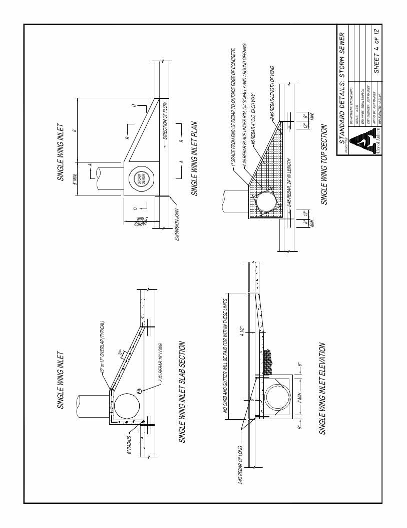
Curb opening inlets are relatively free of clogging problems and offer little interference to traffic operation. Flow capacities for single wing inlets on a continuous slope are shown in Table 7.7. The capacities are based on the City Standard Details for Streets and Storm Drain. The table contains capacities for various continuous longitudinal slopes for both intercepted flow in cubic feet per second (cfs) and bypass flow in cfs. Capacities are based on the standard street cross section for curb and gutter with a manning’s “n” value of sixteen- thousandths (0.016) and an allowable spread of seven and one-half (7.5) feet. Capacities for single wing inlets are based on a minimum curb opening length of thirteen (13) feet and a gutter depression of four (4) inches. All inlet capacities were determined using the FHWA program Urban Drainage Design Program HY-22.
TABLE 7.7 Single Wing Inlet Capacities on a Continuous Slope
Longitudinal Slope (percent)
Intercepted Flow (cfs)
Bypass Flow (cfs)
0.2 0.6 0 0.5 0.9 0 1.0 1.3 0 1.5 1.6 0 2.0 1.8 0 2.5 2.0 0 3.0 2.2 0 3.5 2.4 0 4.0 2.6 0 4.5 2.7 0 5.0 2.8 0.1 6.0 3.0 0.2 7.0 3.1 0.3 8.0 3.2 0.4 9.0 3.3 0.6
10.0 3.4 0.7
The City standard double wing inlet located in a sag section has a capacity of eleven and six- tenths (11.6) cfs with an allowable spread of seven and one-half (7.5) feet.
The design of roadway drainage systems shall limit the number of discharge locations. The City will require that the number of discharge locations be condensed to the maximum extent practicable. The roadway drainage system shall be designed such that the runoff is directly discharged into stormwater storage facilities or natural drainage features. Where discharge of stormwater is required to occur between lots, storm sewer pipe shall be

7. DRAINAGE SECTION
LATEST REVISION: JANAURY 1, 2018 7-15
installed to the rear setback line. If proposed or existing structures are shown on the design plans, the pipes shall be extended ten (10) feet past the rear of the building.
7.3.4 Design Frequency and Spread
Two of the more significant variables that should be considered in the design of roadway pavement drainage are the frequency of the design runoff event and allowable spread of water on the pavement. Table 7.8 lists the allowable spread and design requirements for City road classifications.
The recommended design frequency for depressed sections and underpasses where water can pond and only be removed through the storm drainage system is a 50-year frequency event.
TABLE 7.8 Allowable Spread
Road Classification
Design Frequency Design Spread
Arterial 25-year One-half travel lane
Collector 25-year One-half travel lane Residential Collector 10-year 7.5 feet
Local Commercial 10-year 7.5 feet Local Residential 10-year 7.5 feet
Cul-de-sac 10-year 7.5 feet Alley 10-year One-half width of alley
Marginal Access Roadway 10-year One-half travel lane
Traffic could be unduly disrupted if a sag inlet were to become clogged. Thus the designer should consider locating flanking inlets on each side of the storm structure at the low point of the sag. The inlet spacing design at the sag is performed in two (2) steps. First, the inlet spacing is determined without consideration of the flanking inlets. Because these inlets are considered a backup to the inlet at the actual sump point, the inlet spacing computations should proceed as if these inlets were not present.
Allowable gutter capacity data for the City standard curb and gutter sections are presented in Table 7.9 for various longitudinal slopes with an allowable spread of seven and one-half (7.5) feet. The allowable gutter capacity shall be determined directly from Table 7.9 when computing gutter spread for the street classifications illustrated. The allowable spread of one-half travel lane shall be used for all other street classifications not illustrated in Table 7.9 The City will require detailed gutter capacity design data be submitted as part of the drainage report when designing the drainage for collector and arterial facilities.

7. DRAINAGE SECTION
LATEST REVISION: JANAURY 1, 2018 7-16
Cul-De-Sac/ Local Residential
Local Commercial
Residential Collector/Collector (Pavement Width = 27 feet)
0.6 0.6 0.6 0.9 0.9 0.9 1.3 1.3 1.3 1.6 1.6 1.6 1.8 1.8 1.8 2.0 2.0 2.0 2.2 2.2 2.2 2.4 2.4 2.4 2.6 2.6 2.6 2.7 2.7 2.7 2.9 2.9 2.9 3.2 3.2 3.2 3.4 3.4 3.4 3.7 3.7 3.7 3.9 3.9 3.9
TABLE 7.9 Gutter Capacities for Standard Curb and Gutter Sections
Longitudinal Slope
In Percent 0.2 0.5 1.0 1.5 2.0 2.5 3.0 3.5 4.0 4.5 5.0 6.0 7.0 8.0 9.0
10.0 4.1 4.1 4.1
TABLE 7.10 Gutter Capacities in Cubic Feet per Second for Roll Curb and Gutter Section
Longitudinal Slope In Percent Gutter Capacities (cfs)
0.2 0.5 0.5 0.8 1.0 1.1 1.5 1.3 2.0 1.6 2.5 1.7 3.0 1.9 3.5 2.1 4.0 2.2 4.5 2.3 5.0 2.4 6.0 2.7 7.0 2.9 8.0 3.1 9.0 3.3
10.0 3.5
7.3.4.1 Roadway Inlets The appropriate return period should be used for design of roadway pavement drainage components. Curb and gutter flow characteristics, including spread, for roadways shall be calculated using an appropriate Manning's “n” value, 0 0.016 for asphalt, for the roadway surface.
The design of pavement cross slope on residential streets will conform to the standard roadway sections provided in the City’s standard drawings or ALDOT standard drawings, as applicable.
Rolled curbs are sometimes used in residential areas because they avoid curb cuts for driveways and allow runoff to flow onto adjacent pervious areas. These gutters must also convey the required design storm with spread limited to one-half (0.5) of a driving lane.

7. DRAINAGE SECTION
LATEST REVISION: JANAURY 1, 2018 7-17
7.3.4.2 Inlet Spacing Curb inlets shall be located to facilitate the entrance of water from gutters into the storm sewer system. Inlets will be located or spaced so that the spread criteria are met.
Consideration also must be given to the movement of vehicles to and from adjacent property on turnouts and maintenance of safe pedestrian walkways. All flow will be collected in inlets prior to reaching intersections.
7.3.5 Bridge Decks
Because of difficulties in providing and maintaining adequate deck drainage systems, gutter flow from roadways will be intercepted before it reaches a bridge. Drainage of bridge decks shall be based on the 25-year recurrence interval and shall be included with the bridge plans.
7.3.6 Storm Sewer Pipes
For all hydrologic and hydraulic design and calculations of storm sewer pipes, refer to Table 7.6 unless facilities are under the jurisdiction of the ALDOT. ALDOT requires a 50-year storm return period to be used for design. Only reinforced concrete pipe (RCP) shall be used under roadway surfaces. Corrugated metal pipe shall not be used as part of the drainage system.
7.3.6.1 Manning’s “n” Values Values for Manning's roughness coefficients for various pipe materials are shown in Table 7.11.
TABLE 7.11 Roughness Coefficients for Storm Sewer Pipes
Pipe Material Manning’s “n” Roughness Coefficient
Reinforced Concrete (pipe or box) 0.013 Cast-In-Place Concrete Box 0.013 High Density Polyethylene* (with smooth liner) 0.013
*HDPE pipes shall not be used under roadways but can be used in other locations.
7.3.6.2 Slopes and Hydraulic Gradient The maximum and minimum slopes for storm sewers will conform to the following criteria:
1. Maximum hydraulic gradient will not produce a velocity that exceeds fifteen (15) feet per second (higher velocities require approval from the City Engineer).
2. Minimum desirable physical slope will be the slope that results in a minimum velocity of two and one-half (2.5) feet per second for the design event when the storm sewer is flowing full.
Elevation of the hydraulic gradient for design flow conditions shall be at least one (1) foot below the gutter elevation when minor energy losses are not considered in the design. When minor losses are considered, the design hydraulic gradient can reach the gutter

7. DRAINAGE SECTION
LATEST REVISION: JANAURY 1, 2018 7-18
elevation. Hydraulic calculations shall be included as part of the drainage calculations submittal with the hydraulic gradient shown graphically. Energy losses are discussed in Section 3.2.4.2 “Hydraulic Calculations – Energy Losses” of the SWMM.
7.3.6.3 Storm Sewer Pipe Size, Length and Access Spacing Access spacing is the point in the pipeline where there is access available from the surface, such as a manhole or inlet. Access spacing shall not exceed five hundred (500) feet for pipes less than fifty-four (54) inches in diameter and shall not exceed eight hundred (800) feet under any circumstances. The minimum pipe size shall be fifteen (15) inches. Standard pipe size increments of six (6) inches will be used for pipes larger than eighteen (18) inches.
The minimum box culvert size will be three by three (3 x 3) feet for pre-cast units and four by four (4 x 4) feet for cast-in place units. Increments of one (1) foot in the height or width will be used above this minimum. The “span by height” format shall be used for reporting box culvert dimensions. For example, for the dimension ten by seven (10 x 7) feet, the span is ten (10) feet wide and the height is seven (7) feet.
7.3.6.4 Minimum Clearances Minimum clearances for storm sewer pipe will comply with the following criteria:
1. For the minimum spacing required between road base material and the outside crown of the storm sewer pipe, refer to the City Standard Details.
2. For utility conflicts that involve crossing a storm sewer alignment, the minimum
design vertical clearance between the outside of the pipe and the outside of any conflicting utility shall be one-half foot if the utility has been accurately located by subsurface utility engineering (SUE) at the point of conflict. If the utility has been approximately located, the minimum design clearance shall be one (1) foot. Electrical transmission lines, water or gas mains shall never come into direct contact with the storm sewer.
3. Storm sewer systems shall not be placed parallel to or below existing utilities
in a manner that could cause utility support problems. The horizontal clearance between pipes shall be three (3) feet. Storm sewer junction boxes and inlet boxes shall have a minimum horizontal clearance of two (2) feet from other utilities.
4. When a sanitary line or other utility must pass through a manhole, a
minimum one (1) foot clearance shall be maintained between the bottom of the utility and the flow line of the storm main, and maximum practicable clearance is recommended. Flow will be less obstructed when the utility is placed above or as close as possible to the crown of the pipe and shall be no lower than the top one-third of the pipe. The head loss caused by an obstruction shall be taken into account. Gas and water mains must not pass through inlet and manhole structures. The City will not typically approve conflict boxes for concurrent installation of new sanitary and storm sewer infrastructure. Conflict boxes must receive approval from the Water Resources Management Department for sanitary sewer applications.
7. DRAINAGE SECTION
LATEST REVISION: JANAURY 1, 2018 7-19
Sanitary sewer lines that are permitted in storm sewer boxes shall be ductile iron pipe and a joint of pipe shall be centered in the conflict box.
7.3.7 Roadside Ditches
This section presents standards for design of artificial or manmade open channels, including roadside, non-roadside, median, and interceptor ditches, outfalls, and canals.
7.3.7.1 Design Criteria Ditches, outfalls, detention areas, and other drainage-related features must be provided with berms and other physical access devices that allow maintenance activities.
The maximum allowable side slopes for open channels are as follows:
x Vegetated Residential – 4:1;
x Vegetated Non-residential – 3:1; and
x Riprap–2:1.
A minimum physical slope of one and one-half (1.5%) percent will be used unless otherwise authorized by the City Engineer.
Design documentation for open channels will include the hydrologic analysis and hydraulic analysis, including analysis of channel lining requirements.
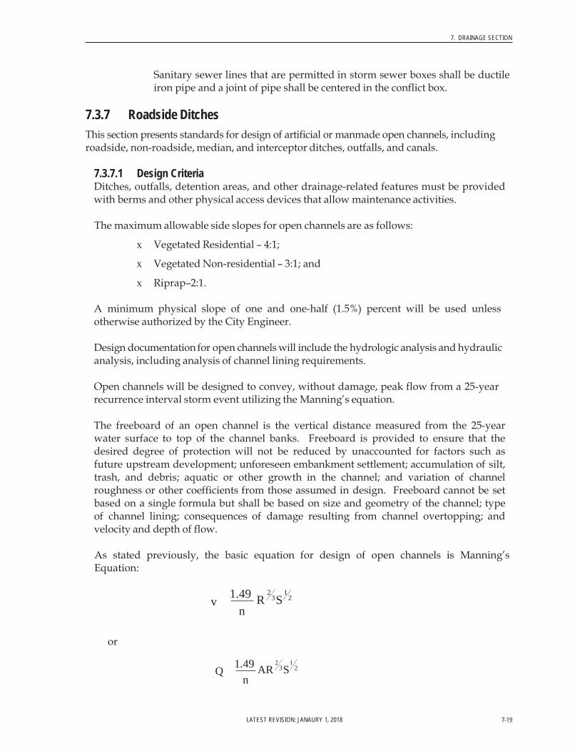
Open channels will be designed to convey, without damage, peak flow from a 25-year recurrence interval storm event utilizing the Manning’s equation.
The freeboard of an open channel is the vertical distance measured from the 25-year water surface to top of the channel banks. Freeboard is provided to ensure that the desired degree of protection will not be reduced by unaccounted for factors such as future upstream development; unforeseen embankment settlement; accumulation of silt, trash, and debris; aquatic or other growth in the channel; and variation of channel roughness or other coefficients from those assumed in design. Freeboard cannot be set based on a single formula but shall be based on size and geometry of the channel; type of channel lining; consequences of damage resulting from channel overtopping; and velocity and depth of flow.
As stated previously, the basic equation for design of open channels is Manning’s Equation:
v 1.49 n
2 1 R 3 S 2
or
Q 1.49 n
2 1 AR 3 S 2

7. DRAINAGE SECTION
LATEST REVISION: JANAURY 1, 2018 7-20
where: V = average channel velocity, feet/second
Q = average channel flow, cfs
n = Manning’s roughness coefficient (provided in Tables 3-1 “Recommended Manning “n” Values For Channels With Bare Soil And Vegetative Linings” and 3-2 “Recommended Manning “n” Values For Channels With Rigid And Semi-Rigid Lining” of the SWMM)
R = hydraulic radius of the channel, ft (area below water surface/wetted perimeter below water surface)
S = slope of the channel bottom, ft/ft
The submittal information for design of open channels shall include graphical representation of the design water surface elevation, cross sections at critical locations and intervals, and maximum average velocity for the 25-year peak flow.
Design of open channels must include an evaluation of channel lining. Maximum velocities for various forms of channel linings are provided in Table 7.12. Grass and sod shall not be used if there is continuous standing or flowing water in the ditch that prohibits grass growth. The design will be reviewed to evaluate whether some form of protective treatment will be required to prevent entry to any ditches that present a hazard to children and, to a lesser extent, all persons. Protective treatment for open channels in the form of fencing will be considered when a potential hazard exists. The design and location of open channels will comply with roadside safety and clear zone requirements.
TABLE 7.12 Maximum Velocities for Various Channel Linings
Material Maximum Velocity (feet per second)
Silt or fine sand 1.50
Loam 1.75 Stiff Clay 3.75
Grass 3.00 Sod 4.00
Rigid 1 10.00 Geotextile grid 2 4.00-8.00
1. Higher velocities may be acceptable for rigid linings if appropriate data is available and provisions for energy dissipation is provided
2. Varies with grid type 7.3.8 Culverts
A culvert conveys water underneath roads, railroads, and embankments. In addition to this hydraulic function, it must also carry construction and highway traffic and earth loads; therefore, culvert design involves both hydraulic and structural design. The hydrologic and hydraulic design of culverts is addressed in this section. The hydraulic design must prevent risks to traffic, property damage, and failure from floods and include sound engineering practice and economics. This section describes hydraulic aspects of culvert design,

7. DRAINAGE SECTION
LATEST REVISION: JANAURY 1, 2018 7-21
construction and operation of culverts, and makes references to structural aspects only as they are related to hydraulic design.
7.3.8.1 Discharge The design discharge for culverts is based on the 25–year recurrence interval for culverts handling drainage from primarily the internal facilities of the development. For culverts designed to accept drainage from upstream areas outside of the development, the City requires that the Applicant determine design flows for the entire upstream area. Furthermore, if the design storm is increased by the development for any recurrence interval, the Applicant must conduct calculations further downstream to, at least, the first City-maintained stormwater management facility. New development must not have adverse impacts on City stormwater management facilities.
There shall not be any overtopping of roadways for the 100-year recurrence interval. If ponding occurs at the culvert entrance and a reduction in discharge downstream occurs as a result of storage effects, reservoir routing calculations shall be used to determine the reduction in peak flow.
7.3.8.2 Culvert Material All culverts shall be constructed using reinforced concrete pipe unless otherwise approved by the City Engineer.
7.3.8.3 Length and Slope The following factors related to length and slope of the culvert shall be evaluated:
1. Channel invert of the stream being conveyed
2. Geometry of the roadway embankment
3. Skew angle of the culvert
In general, the culvert slope shall be chosen to approximate the existing streambed slope.
7.3.8.4 Velocity Limitations A minimum velocity of two and one-half (2.5) feet per second when the culvert is flowing full is recommended to ensure a self-cleaning condition during partial depth flow. When velocities below this minimum are anticipated, installation of a sediment trap upstream of the culvert is required.
7.3.8.5 Outlet Protection Transitions from culverts, pipes or other outlet structures to natural channel systems that create high velocities or excessive flow conditions must be mitigated with outlet protection measures. Culverts, pipes, or other outlet structures within the clear zone shall include a sloped headwall unless determined by the engineer that one is not warranted.
The design velocity at any stormwater management system outlet shall not result in velocities that equal or exceed the erosive velocity of the receiving channel, unless energy dissipation and permanent erosion protection measures are placed at the outlet. Energy and outlet dissipation shall discharge onto stable channel sections. If velocities exceed permissible velocities for the channel lining, outlet protection is required.

7. DRAINAGE SECTION
LATEST REVISION: JANAURY 1, 2018 7-22
Table 7.13 can be used as general guidance in the selection of the appropriate protection for culvert outlets based on outlet velocity.
TABLE 7.13 General Guidance for Selection of Outlet Protection
Velocity (feet per second) Type of Outlet Protection
Less than 5.0 Generally protection not required (may need to provide protection
if channel is highly erodible)
5.0 to 12.0 Riprap apron
12 to 20 Baffled outlet
Greater than 20.0 Impact basin
Additional detailed documentation and guidance on the selection and design of outlet protection for culverts can be in FHWA publication HEC-14 “Hydraulic Design of Energy Dissipators for Culverts and Channels”.
7.3.8.6 Design Calculations A flow chart for performing culvert design calculations is provided in Figure 3-7 and a worksheet for performing calculations for standard culvert design is provided in Figure 3-8 “Culvert Design Form” of the SWMM. The methodology and procedures for standard culvert design is discussed in Section 3.4.5 “Culverts – Design Calculations” of the SWMM.
The allowable headwater elevation is determined from an evaluation of conditions upstream of the culvert and proposed or existing roadway elevation. The following criteria shall be analyzed:
1. Non-damaging or permissible upstream flooding shall be identified. Headwater shall be kept below these elevations.
2. Headwater depth for the design discharge shall not overtop the road.
3. Headwater depth for the design discharge(s) shall not cause water to rise
above the top of approach channels adjacent to improved land and shall not exceed the existing conditions 100-year flood elevation.
4. Other site-specific design constraints shall be addressed as required. The
constraint that gives the lowest allowable headwater elevation will establish the basis for hydraulic calculations.

7. DRAINAGE SECTION
LATEST REVISION: JANAURY 1, 2018 7-23
7.4 HYDRAULIC DESIGN OF STORMWATER STORAGE SYSTEMS
Types of stormwater storage facilities that are appropriate in the City jurisdictional area are identified in this section. In addition to the types of storage, general design considerations, flow control structures, and methodology for conducting storage reservoir routing are addressed.
Peak discharges and runoff volumes for all recurrence intervals must be evaluated at the first downstream City-maintained stormwater management facility and other comparison points, discussed in Section 7.4.1 “Comparison Points” so that structures and stormwater management system currently in place are not flooded or the existing level of service is compromised. If the increase in peak stormwater discharge or runoff volume compromises the current structures and system, necessary steps must be taken to mitigate the increase in peak flow or runoff volume.
Detention pond provisions of this section typically do not apply to developments of less than one (1) acre. Certain developments less than one (1) acre may require that detention be provided.
7.4.1 Comparison Points
Comparison points are locations where existing conditions and post development conditions stormwater flow characteristics such as peak flow, volume and hydrographs can be compared to evaluate the impact of the proposed development on stormwater runoff characteristics. Comparison points are locations:
1. Where stormwater runoff leaves the site of the proposed development(s).
2. Of the first downstream City owned stormwater management infrastructure.
3. Between the development and first downstream City owned stormwater infrastructure where existing flooding problems exist or any increase in stormwater runoff or peak flow causes increased flooding on private property.
In some cases the first downstream City owned stormwater management infrastructure is not within a reasonable distance downstream. In these situations, the “10% rule” will be used to determine the downstream point of analysis. The ten percent rule involves analyzing the runoff hydrograph at a point downstream where the development property comprises 10% of the area of the drainage basin at that point. In all cases, unless approved by the receiving property owner, outlet flow conditions shall be at or below predevelopment conditions.
7.4.2 Types of Storage Systems
Types of stormwater storage systems described in this section are detention and retention basins, underground storage facilities, and regional detention. Detention basins slow stormwater runoff rates, and allow little or no infiltration.
Storage systems are also used to address water quality requirements of the City’s Phase II Stormwater Permit. Additional information for pollutant removal, water quality benefits

7. DRAINAGE SECTION
LATEST REVISION: JANAURY 1, 2018 7-24
inspection, and operation and maintenance requirements for various stormwater controls can be found in the WRM Manual.
7.4.2.1 Detention Basins Detention basins offer temporary storage accompanied by controlled release of the stored water. Detention basins are placed with the basin invert above the seasonal high water table and outlet near the invert of the pond so that there will be no standing water left after the design storm is routed through the structure. When designing detention basins, the following items shall be considered:
1. Release rate
2. Detention volume
3. Grading and depth requirements
4. Outlet works
5. Discharge water quality
7.4.2.2 Retention Basin Retention basins are constructed basins that have a permanent pool of water throughout the year or wet season and generally are found in locations where groundwater is high and/or percolation is poor. Additional storage is provided above the permanent pool for peak discharge attenuation and water quality treatment volume.
All retention and detention basins must meet the applicable dam design guidelines discussed in Section 6.0 “Geotechnical” of this Manual.
7.4.2.3 Underground Detention Systems Underground stormwater detention systems capture and store stormwater runoff in large pipes or other subsurface structures like concrete vaults. Stormwater runoff typically enters the system through a riser pipe connected to a catch basin or curb inlet and flows into a series of pipes, chambers, or compartments for storage. Captured stormwater runoff is retained throughout the storm event and released directly into the stormwater management system through an outlet pipe. Underground detention systems can be constructed from concrete, steel, or plastic materials. Each material has advantages, disadvantages, and specific applications. Underground detention vaults are box-shaped stormwater storage facilities typically constructed with reinforced concrete. Underground detention tanks are underground storage facilities typically constructed with large diameter metal or plastic pipe. All underground detention systems serve as an alternate to surface dry detention or retention storage, particularly for space-limited areas where there is not adequate land or land cost is a major consideration.
Basic storage design and routing methods are the same as for detention basins except that the bypass for high flows is typically included. Underground detention systems are not intended for water quality treatment.
Location
x Underground detention systems are to be located downstream of other structural stormwater controls if used to provide water quality treatment.

7. DRAINAGE SECTION
LATEST REVISION: JANAURY 1, 2018 7-25
x Because of the cost of installing underground detention systems, typically the maximum contributing drainage area to be served by a single underground detention system is approximately twenty-five (25) acres.
General Design
x Underground detention systems are sized to control the stormwater runoff volume for the 2-year through 100-year recurrence intervals such that post- development flows are equal to or less than pre-development flows. Routing calculations, located in Section 7.2.7 “Stormwater Runoff Hydrographs” must be used to demonstrate that the storage volume is adequate.
x Slopes of underground pipes, chambers, and vaults of underground
detention systems shall be designed with a maximum slope of two (2%) percent to allow drainage of the system if infiltration is not utilized. If infiltration is utilized, the pipes, chambers, and vaults shall be constructed on a flat slope.
x Minimum pipe diameter for underground detention systems shall be thirty-
six (36) inches to facilitate maintenance.
x Underground detention systems shall be watertight. Certain underground detention facilities may be required to be designed by a structural engineer.
x Adequate maintenance and inspection access must be provided for all
underground detention systems. Access must be provided over the inlet pipe and outflow structure. Access openings can consist of a standard frame, grate and solid cover, or a removable panel. Vaults with widths of ten (10) feet or less shall have removable lids. Access ports shall be provided for pole camera and cleaning equipment. Additional access points may be required to facilitate inspection and maintenance. The minimum number of access points shall be one (1) per chamber or as determined during review of the proposed underground detention system.
x High flow bypass shall be included in the underground detention system
design to safely pass flows that exceed the design flow.
Maintenance x Trash, debris, and sediment in the underground vaults or tanks shall be
removed annually. Repairs to the inlet and outlet shall be made as needed after each inspection.
7.4.2.4 Regional Detention Regional Detention refers to a stormwater facility that will provide detention for two (2) or more commercial or residential development sites. Multiple development sites may exist on a single lot of record. In these cases, the detention facility serving those development sites would be considered Regional Detention and shall be designed and constructed in accordance with this section of the Manual.

7. DRAINAGE SECTION
LATEST REVISION: JANAURY 1, 2018 7-26
For developments proposing to utilize Regional Detention, the facility must be designed to accommodate full build-out of all proposed lots draining to it. Likewise, the public stormwater conveyance infrastructure must be designed to accommodate full build-out of all lots draining to the Regional Detention facility. The proposed detention facility, as designed for full build-out, shall be installed with the initial improvements. No construction phasing of the regional facility is permitted.
The drainage report that contains design information for Regional Detention facilities shall clearly indicate the assumed CN values, or runoff coefficients, used in the design. A composite value shall be provided for each proposed lot in the subdivision. These composite CN values, or runoff coefficients, shall be clearly indicated on the post- development drainage basin map(s).
The Regional Detention facility shall be certified in accordance with Section 7.4.4 “Stormwater Storage Facility Certification” of this Manual. Certification of the regional facility is required, as designed for full build-out, prior to the first certificate of occupancy of the overall development.
If the Regional Detention facility was used for sediment control during infrastructure construction, the filter structure and excess sediment must be removed from the facility prior to certification.
Individual lots draining to the facility shall be designed to control sediment within the boundaries of each lot. Runoff from individual lots shall be directed to the installed stormwater conveyance infrastructure designed to accommodate that lot. No increase in peak runoff flow rate will be permitted onto adjacent lots, as a result of a lot built-out, unless the runoff is directed into the original conveyance system designed to handle that runoff.
7.4.3 Storage Design
This subsection provides guidelines related to the design of stormwater storage systems. These storage systems shall be designed by a licensed professional engineer in the State of Alabama who is qualified by reason of education and experience in the field of stormwater design. Design drawings, specifications, and design calculations shall be submitted to the City for review. The City requires a Stormwater Drainage Checklist be prepared as part of the DRT submittal package for all projects that require stormwater detention. The checklist shall be included as the first page of the drainage report. Once the stormwater storage system is constructed, this engineer must certify that the system has been constructed properly and that it will function and operate for the purpose that it was designed. NRCS methodology shall be used for all hydrologic analyses for storage facility design. The modified rational methodology shall not be used for storage design.
The City may elect not to incorporate detention if a development drains into a natural major water course and the post-development discharge does not cross another property or portions of the developed property before it is introduced into the natural major water course. In order to illustrate that detention will not have an adverse impact on existing infrastructure the City will require analysis at critical crossings (comparison points) downstream of the development.

7. DRAINAGE SECTION
LATEST REVISION: JANAURY 1, 2018 7-27
7.4.3.1 Length to Width Ratio The inlet and the outlet of the basin should be located to prevent short-circuiting and to maximize flow through the basin to improve water quality benefits. If the pond is performing as a sediment basin, the ratio between the length and width (L/W) will be 2:1 or larger. If this ratio cannot be attained because of topographic constraints, then additional provisions, such as a temporary baffle wall, shall be incorporated into the basin to create a L/W of 2:1.
7.4.3.2 Release Rate Release rates for managing stormwater peak discharge by detention will be based on the following conditions:
1. Post-development peak discharge is less than or equal to pre-development peak discharges for the 2-, 5-, 10-, and 25-year, 24-hour design storm events.
2. Limit release rate based on the discharge capacity (level of service of stormwater
management system from the development to the first City- maintained stormwater infrastructure) downstream from the project as discussed in Section 7.4.1 “Comparison Points”.
7.4.3.3 Detention Volume Detention volume shall be adequate to provide attenuation of the post-development peak discharge rates to the allowable release rate set according to provisions in Section 7.4.3.2 “Release Rate”. Hydraulic features of the outlet control structure shall be designed such that all stormwater runoff volume will be released within seventy-two (72) hours.
Routing calculations shall be consistent with the procedures outlined in Section 7.4.3.8 “Routing Techniques”. If sediment accumulation occurs during construction resulting in a loss of detention volume in the basin, design dimensions must be restored before submitting the as-built certification.
7.4.3.4 Depth A minimum freeboard of one-half (0.5) feet shall be provided above the peak 100-year design flood elevation.
7.4.3.5 Outlet Works The principal spillway shall convey the 25-year discharge rate for total watershed development without allowing flow to enter the emergency outlet. The emergency outlet shall be sized to safely pass the 100-year design storm. A smooth and stable transition to the first City-maintained stormwater management facility or other comparison point as discussed in Section 7.4.1 “Comparison Points” shall be provided.
7.4.3.6 Sediment Storage Sediment storage shall be provided in basins to contain three thousand six hundred (3,600) cubic feet per contributing drainage acre per the City standard for erosion control. This volume may be maintained in the permanent facility. Additional guidance and a sediment basin design data sheet can be found in the WRM Manual. It is recommended that a sediment sump (forebay or trap) be installed at the inlet of the pond structure to allow for sediment accumulation and clean out. Additional information on sediment storage can be found in the WRM Manual. This sediment storage shall not be included in the storage volume required to meet stormwater peak flow and volume requirements.

7. DRAINAGE SECTION
LATEST REVISION: JANAURY 1, 2018 7-28
7.4.3.7 Outlet Protection Refer to Section 7.3.8.5 “Culverts – Outlet Protection” for outlet protection requirements and guidance.
7.4.3.8 Routing Techniques The primary function of a stormwater storage facility is to reduce the peak flow of a hydrograph to a desired value. A reservoir routing procedure is used to determine the peak flow reduction by a stormwater storage facility.
The engineer of record shall use a standard computer software program to estimate the performance of the detention basin. These programs must base the routing on a storage continuity approach, such as the level-pool routing method. Documentation in the drainage report shall include input variables and peak flow rates and stages for each design storm. The configuration of the outlet structure shall be clearly described. Furthermore, stage (or elevation) versus storage and discharge table(s) shall be provided. Additional design criteria discussed in this section, but not necessarily contained in the routing procedures, shall be addressed in the application as supporting information and/or contained within the design documents. Example 4.1 “Sizing of the Basin for Stormwater Attenuation” in the SWMM is an example of sizing a storage facility using computer software.
The Storage Indication Method is recommended for performing manual reservoir routing calculations for final design of detention facilities. Methodologies, procedures, and an example for manual routing are found in Section 4.4.1 “Storage Routing – Manual Routing Calculations” of the SWMM.
7.4.3.9 Stage-Storage and Stage-Discharge Stage-storage and stage-discharge relationships must be determined for storage facility analyses. Documentation included in the drainage report shall include assumptions, calculations and summary of stage-storage and stage-discharge relationships used for all the hydrologic analyses.
If the invert of the outlet structure is above the pond invert, the storage shall be based on the outlet invert since any storage below the outlet invert is “dead” storage. Figure 4-5 “Example Stage-Storage Curve” in the SWMM shows an example of a stage-storage curve.
A stage-discharge curve defines the relationship between depth of water and the discharge or outflow from a storage facility. A typical storage facility has two outlets or spillways: a principal outlet and a secondary (or emergency) outlet. The principal outlet shall be designed with a capacity sufficient to convey the design flows without allowing flow to enter the emergency spillway. A pipe culvert, weir, or other appropriate outlet can be used for the principal spillway or outlet. Figure 4-6 “Example Stage-Discharge Curve” in the SWMM shows an example of a stage-discharge curve.
The emergency spillway is sized to provide a bypass during a flood that exceeds the design capacity of the principal outlet. This spillway shall be designed taking into account the potential threat to downstream areas if the storage facility were to fail.

7. DRAINAGE SECTION
LATEST REVISION: JANAURY 1, 2018 7-29
7.4.3.10 Storage Basin Safety Access management may be required to prevent entry to facilities that present a hazard to children and, to a lesser extent, all persons. Fences and warning signs may be required for storage facilities where the following conditions exist:
1. Rapid changes in stage.
2. Water depths either exceed two and one-half (2.5) feet for more than twenty- four (24) hours or are permanently wet and have side slopes steeper than four (4) horizontal to one (1) vertical (4H:1V).
Consideration of access for maintenance and emergency response must be addressed for storage basins where fences are required. Basin side slopes shall be 4H:1V or flatter from two and one-half (2.5) feet below normal water level to the toe of slope.
Storage basins shall be designed with the following additional safety factors taken into consideration when feasible:
1. Outlets shall be placed away from areas of heavy public use.
2. Integrate outlet culvert into an outlet structure that has smaller openings and/or utilize a sloping trash/safety rack at the entrance (bars on face of trash rack shall be spaced to provide four (4) to five (5) inch clear openings between bars).
3. Grates shall be provided for all control structure openings greater than one (1) foot.
4. Grade overall site with safety in mind (i.e., mild side slopes leading to and within the storage facility).
5. Separate inflow and outlet pipes by long distances and ensure inflow and outflow pipes are not directly across from each other.
6. Eliminate shallow, shallow-stagnant water in bottom of “dry” basins that can
be conducive to mosquito breeding (determine maximum groundwater elevations prior to design).
7.4.4 Stormwater Storage Facility Certification
The City will require that storage facilities constructed for proposed developments complete the Stormwater Storage Facility Final Certification Form which can be found in Appendix S, prior to issuance of a Certificate of Occupancy for site plan developments.
The City will require that storage facilities for subdivision developments complete the City Storage Facility Final Certification Form prior to final approval and acceptance of the subdivision. If deemed necessary by the engineer responsible for the design of the storage facility and the City Engineer, a letter of credit, cashier’s check, or surety bond may be posted to allow for final approval and acceptance when there is cause not to complete the required work on the storage facility. The bond amount will be equal to the estimated cost of construction to meet the approved storage facility design.
The City Stormwater Storage Facility Final Certification Form shall be stamped and signed

7. DRAINAGE SECTION
LATEST REVISION: JANAURY 1, 2018 7-30
by a licensed professional engineer in the State of Alabama that was responsible for the design of the storage facility for both site plan and subdivision developments.
It is the responsibility of the engineer of record that completed the design of the storage facility to compare the as-built conditions with those of the approved design. If the as-built conditions differ from those of the approved design, complete submissions of as-built drawings for the storage facility will be required. The as-built information shall be delivered in a format similar to the original storage facility design. The City will review the as-built drawings and may require that the approved drainage report be revised to reflect the as-built conditions. In these situations, the City will not accept a Stormwater Storage Facility Final Certification Form until the as-built and revised drainage report has been approved.
7.4.5 Operation and Maintenance
The City will require that a Stormwater Storage Facility Operations and Maintenance Agreement (O&M Agreement) be submitted for all proposed storage facilities. The O&M Agreement can be found in Appendix T. The O&M Agreement must include a description of the storage facility and its components and provide a maintenance schedule to ensure that the storage facility is operating as designed. If a storage facility is designed to provide sediment storage during construction, the O&M Agreement must also provide a maintenance schedule during construction operations. The O&M Agreement is required to be submitted prior to any certificates of occupancy being issued on sites that have newly constructed storage facilities.
The City will require that an O&M Agreement be executed by the entity responsible for the upkeep and maintenance of newly constructed storage facilities. The O&M Agreement must be submitted to the City with the Storage Facility Final Certification Form. The O&M Agreement will contain the previously approved Operation and Maintenance Plan and identify the entity responsible for perpetual care, operation, maintenance, and associated liabilities of the storage facility along with a letter from the entity accepting the responsibilities as outlined in the O&M Agreement. The City will require that the O&M Agreement be recorded.
In addition to the owner performed inspections identified in the O&M Agreement, the City conducts annual inspections of all storage facilities within the City. The City will provide a copy of the inspection report to the entity responsible for the maintenance. This maintenance and/or remedial work identified during the City’s inspection may be in addition to the required maintenance identified in the O&M Agreement. The owner of the pond shall submit evidence that the required maintenance and/or remedial repairs identified during the City inspections have been completed. Failure to follow the O&M Agreement and/or complete the necessary repairs identified during the City inspection will result in enforcement actions.

7. DRAINAGE SECTION
LATEST REVISION: JANAURY 1, 2018 7-31
7.5 FEMA REQUIREMENTS
This section is intended to provide guidance for proposed development within the 100-year floodplain. Persons using this Manual whose proposed development is located within the 100-year floodplain must meet all requirements in the City Code and National Flood Insurance Program (NFIP) regulations.
Established under the National Flood Insurance Act of 1968 and broadened with the passage of the Flood Disaster Act of 1973, the NFIP provides federally supported flood insurance to community residents that voluntarily adopt and enforce regulations to reduce future flood damage. As part of the program, the federal government defines minimum standards for floodplain development that the local communities must adopt to be eligible for program benefits. Development of property located within the regulatory floodplain must comply with all applicable City ordinances, regulations, and guidelines.
The determination of all floodplain boundaries shall be based on the maximum recorded or projected flood elevation applicable. The areas constituting a riverine floodplain shall be determined by reference to the following sources in the order indicated below. If the first source is not available, one or both of the others shall be used:
1. Flood Insurance Rate Maps (FIRM) prepared by the Federal Emergency Management Agency;
2. Floodplain Information Maps and Profiles, prepared by the U.S. Department of
Agriculture, Natural Resources Conservation Service;
3. Hydrologic Investigations Atlas, prepared by the U.S. Department of the Interior, Geologic Survey – these studies cover the entire area of Auburn and show the flood of record, rather than a projected 100-year flood, for each area subject to flooding.
On-site topographic surveys shall be performed to locate the precise floodplain line on a parcel. The survey shall use the flood profile contained in the sources listed above or, if no such profile exists, by performing standard runoff calculations.
7.5.1 Floodplain Protection Ordinance
All provisions of the latest version of the Flood Damage Prevention Ordinance contained in the City Code shall be applicable to development in the floodplain.
7.5.2 Permanent Open Space
The City strongly encourages that all floodplain areas be designated as permanent open space. However, should a development propose an encroachment into the 100-year floodplain the regulations set forth in the Zoning Ordinance, Subdivision Regulations, and WRM Manual shall also apply in addition to the requirements set forth in this section.
7. DRAINAGE SECTION
LATEST REVISION: JANAURY 1, 2018 7-32
7.5.3 Building Elevation
All buildings or any residential, institutional, office, commercial and entertainment, commercial recreation, recreational rental dwelling, or nursery uses (other than those specifically named in this section) may be permitted, provided that all floor areas shall be raised so that no floor, or its structural supports, or any utility line has less than one (1) foot of clearance between its lowest point and the 100-year flood elevation. Any reduction of cross-sectional area due to vertical supporting members shall be offset by compensatory storage.
7.5.4 Installation of Fill Materials
Fill may be placed within the floodplain only when allowed by the City Engineer and pursuant to applicable City Ordinances and code requirements and in accordance with the following provisions:
1. Compensatory storage shall be provided to offset the storage lost through the filling.
2. All changes in velocity, depth of flood elevation, or storage shall be limited to
the property owners who have been granted flood or flow easements, provided that in no event shall an increase in flood elevation be permitted if it would affect any existing building or bring any building to within one (1) foot of the flood elevation.
3. In no instance shall the depth of fill in a riverine floodplain exceed five (5) feet,
nor shall any fill be placed within twenty-five (25) feet of the stream channel or in a location which might be endangered by or accelerate a meander. In an inland depressional floodplain the depth of fill measured from the natural grade to the new surface shall not exceed five (5) feet.
4. Fill shall consist of soil or rock materials only; sanitary landfills shall not be
permitted in the floodplain. Further, all fill areas shall be stabilized with material that will insure and protect against erosion hazards, undercutting, and undermining.
7.5.5 Filling in Floodplain
The filling of areas within the 100-year floodplain shall be approved only where plans and specifications have been submitted that meet all requirements of this section, other applicable City requirements, other applicable State and Federal requirement, and where the following conditions exist which necessitate filling within the floodplain:
1. The property would otherwise be able to accommodate at least one (1) residential dwelling with a lot meeting requirements of the Zoning Ordinance but cannot, because of the floodplain, accommodate even one (1) single-family unit; or,
2. That the location and/or configuration of the buildable land are such that the
intensity of the permitted land-use cannot be realized without filling in the

7. DRAINAGE SECTION
LATEST REVISION: JANAURY 1, 2018 7-33
floodplain. In no event shall the filling of the floodplain be permitted to increase the allowable buildable area.
As stated in Section 7.5.5 “Filling in the Floodplain”, compensatory storage shall be provided to offset floodplain storage lost as a result of placing fill within the 100-year floodplain. For every cubic yard of material placed in the floodplain a cubic yard of compensating cut must be provided within the 100-year floodplain.
7.5.6 Conditional Letter of Map Revision
A Conditional Letter of Map Revision (CLOMR) is a process where the Federal Emergency Management Agency (FEMA) will provide review and comments on a proposed project that would, upon completion, affect the hydrologic or hydraulic characteristics of a flooding source and result in a change to the existing regulatory floodway, effective Base Flood Elevation (100-year flood elevation) or the Special Flood Hazard Area (100-year floodplain). The CLOMR issued by FEMA does not officially revise an effective National Flood Insurance Program map but it indicates whether the project, if constructed as proposed, would be recognized by FEMA.
The City Engineer will require a CLOMR for a proposed project if the proposed project:
1. Results in a change to the floodplain boundary; or
2. Results in an increase of one-tenth (0.10) of a foot increase in the 100-year flood.
3. Results in an encroachment into the floodway with an increase in the 100-year flood elevation greater than zero (0.00) feet.
If a CLOMR is required, the CLOMR must be obtained prior to work occurring in the affected area. The CLOMR must be submitted using the appropriate FEMA form and in accordance with FEMA requirements.
7.5.7 Letter of Map Revision
A Letter of Map Revision (LOMR) is an administrative procedure that FEMA uses to officially revise the effective published Flood Insurance Rate Map. If a CLOMR has been obtained for a proposed project, a LOMR must be obtained after the project has been completed prior to the City issuing a Certificate of Occupancy.
7.5.8 Floodway
As stated in the City Code, encroachments into the floodway are prohibited. Development may be permitted, however, provided it is demonstrated that all requirements of the Code of Federal Regulations (CFR) for the NFIP are met.
The City may approve an encroachment into the floodway provided a No Rise Certification is provided. The No Rise Certification must be submitted by a licensed professional engineer in the State of Alabama.

7. DRAINAGE SECTION
LATEST REVISION: JANAURY 1, 2018 7-34
7.6 DRAINAGEWAYS
Regrading, stripping of vegetation, or filling is permitted in these areas, provided that the resultant new drainageway has less velocity than existed previously or reduces streambank erosion through the provision of erosion control measures approved by the City Engineer.

This page intentionally left blank.

APPENDIX R. Storm Sewer Standard Details

This page intentionally left blank.


30


TYPI
CAL T
RENC
H CR
OSS-
SECT
ION
(N.T
.S.)
TYPI
CAL O
PEN
DITC
H CR
OSS-
SECT
ION

APPENDIX S. Stormwater Storage Facility Final Certification

This page intentionally left blank.

Stormwater Storage Facility Final Certification Form Public Works Department
171 N. Ross Street, Suite 200 Auburn, Alabama 36830
(334) 501-3000 FAX (334) 501-7294 www.auburnalabama.org
Project Name: __________________________________________________________
Storage Volume Summary:
2-Year 5-Year 10-Year 25-Year 100-Year Design Volume
As-Built Volume Outlet Device Elevation Summary:
Size and Description
Information Design Elevation
As-Built Elevation Design As-Built
Outlet Device #1
Outlet Device #2
Outlet Device #3
Outlet Device #4
Outlet Device #5 Emergency
Spillway Bottom of Pond
(As necessary, please provide any comments or other information necessary to accurately describe the as-built storage facility conditions in a separate Memorandum and attach to this form)
By placing my professional stamp and signature on this form, I certify that this storage facility is constructed in accordance with the approved design on file with the City of Auburn and that all temporary sediment storage components have been removed. I further certify that the all drainage areas designed to be attenuated in the storage facility in fact do drain to this facility and the outlet peak discharge rates are equal to or less than the peak discharge rates as approved for the development.
Signed: ____________________________ Seal:
Date:______________________________

This page intentionally left blank.

APPENDIX T. Stormwater Storage Facility Operations

This page intentionally left blank.
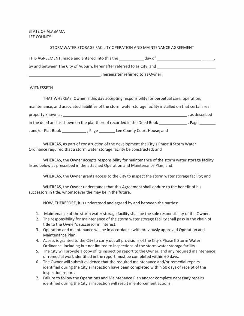
STATE OF ALABAMALEE COUNTY
STORMWATER STORAGE FACILITY OPERATION AND MAINTENANCE AGREEMENT
THIS AGREEMENT, made and entered into this the day of _____ ,
by and between The City of Auburn, hereinafter referred to as City, and
, hereinafter referred to as Owner;
WITNESSETH
THAT WHEREAS, Owner is this day accepting responsibility for perpetual care, operation,
maintenance, and associated liabilities of the storm water storage facility installed on that certain real
property known as , as described
in the deed and as shown on the plat thereof recorded in the Deed Book , Page
, and/or Plat Book , Page Lee County Court House; and
WHEREAS, as part of construction of the development the City’s Phase II Storm WaterOrdinance required that a storm water storage facility be constructed; and
WHEREAS, the Owner accepts responsibility for maintenance of the storm water storage facilitylisted below as prescribed in the attached Operation and Maintenance Plan; and
WHEREAS, the Owner grants access to the City to inspect the storm water storage facility; and
WHEREAS, the Owner understands that this Agreement shall endure to the benefit of hissuccessors in title, whomsoever the may be in the future.
NOW, THEREFORE, it is understood and agreed by and between the parties:
1. Maintenance of the storm water storage facility shall be the sole responsibility of the Owner.2. The responsibility for maintenance of the storm water storage facility shall pass in the chain of
title to the Owner’s successor in interest.3. Operation and maintenance will be in accordance with previously approved Operation and
Maintenance Plan.4. Access is granted to the City to carry out all provisions of the City’s Phase II StormWater
Ordinance, including but not limited to inspections of the storm water storage facility.5. The City will provide a copy of its inspection report to the Owner, and any required maintenance
or remedial work identified in the report must be completed within 60 days.6. The Owner will submit evidence that the required maintenance and/or remedial repairs
identified during the City’s inspection have been completed within 60 days of receipt of theinspection report.
7. Failure to follow the Operations and Maintenance Plan and/or complete necessary repairsidentified during the City’s inspection will result in enforcement actions.

Future communications in writing, from the City to the Owner, shall be sent to the Owner’saddress, as stated below.
In Witness Whereof, the parties have executed this Agreement the day and year above firstwritten.
By:OWNER
GRANTOR’S SIGNATURE
ADDRESS
CITY, STATE
TELEPHONE NUMBER
I, , a Notary Public of said County and
State, certify that personally appeared
before me this day and acknowledged that he/she is
of , an Alabama company
and that by authority duly given and as the act of the
company, the foregoing instrument was signed in its name and by its , sealed
with its corporate seal and/or attested by him/her as its .
Witness my hand and seal this day of day , __________.
Notary Public
(SEAL)
My Commission Expires: .
APPENDIX T-1. Subdivision Operation and Maintenance Agreement

This page intentionally left blank.
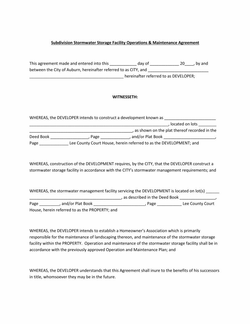
Subdivision Stormwater Storage Facility Operations & Maintenance Agreement
This agreement made and entered into this ____________ day of _____________ 20____, by and between the City of Auburn, hereinafter referred to as CITY, and ___________________________ __________________________________________ hereinafter referred to as DEVELOPER;
WITNESSETH:
WHEREAS, the DEVELOPER intends to construct a development known as _______________________ ______________________________________________________________, located on lots ________ ______________________________________________, as shown on the plat thereof recorded in the Deed Book _________________, Page _____________, and/or Plat Book _______________________, Page _____________ Lee County Court House, herein referred to as the DEVELOPMENT; and
WHEREAS, construction of the DEVELOPMENT requires, by the CITY, that the DEVELOPER construct a stormwater storage facility in accordance with the CITY’s stormwater management requirements; and
WHEREAS, the stormwater management facility servicing the DEVELOPMENT is located on lot(s) ______ _________________________________________, as described in the Deed Book ________________, Page _________, and/or Plat Book _______________________, Page ___________ Lee County Court House, herein referred to as the PROPERTY; and
WHEREAS, the DEVELOPER intends to establish a Homeowner’s Association which is primarily responsible for the maintenance of landscaping thereon, and maintenance of the stormwater storage facility within the PROPERTY. Operation and maintenance of the stormwater storage facility shall be in accordance with the previously approved Operation and Maintenance Plan; and
WHEREAS, the DEVELOPER understands that this Agreement shall inure to the benefits of his successors in title, whomsoever they may be in the future.

NOW THEREFORE, in consideration of the mutual covenants and agreements, IT IS AGREED, as follows:
1. Each lot in the DEVELOPMENT, and any future subdivision of lots within the DEVELOPMENT, shall have attached to it an equal and undividable ownership in the PROPERTY and each and every lot owner, including lots retained by the DEVELOPER, shall be considered the “OWNER” of the stormwater storage facility(s) located on the PROPERTY. Subject to the other terms of the agreement, the Homeowner’s Association shall, as the agent of the OWNER, thereafter be primarily responsible for the landscaping and maintenance of the stormwater storage facility located on the PROPERTY. If the Homeowner’s Association is never created, is not responsive, or is dissolved, then the OWNER shall be responsible for all obligations of this agreement.
2. The CITY is authorized to access the PROPERTY to inspect the storm water storage facility as necessary to ascertain that the practices are being maintained and operated in accordance with the approved stormwater management plan.
3. The CITY is authorized to perform the corrective actions identified in the annual stormwater storage facility inspections report if the OWNER or Homeowner’s Association does not make the required corrections in the specified time period.
4. Each lot in the DEVELOPMENT, and any future subdivision of lots within the DEVELOPMENT, shall be jointly and severally liable for any expense or cost incurred by the CITY to preserve, maintain, or restore the stormwater storage facility, or landscaping located on the PROPERTY. The CITY shall be empowered, without notice of hearing, to levy a special assessment against each OWNER within the DEVELOPMENT, and any future subdivision of the lots within the DEVELOPMENT, and each and every OWNER agrees to pay for any such special assessment for expenses incurred by the CITY for the maintenance of stormwater facility(s) should they not be maintained by the OWNER or the Homeowner’s Association.
5. DEVELOPER, OWNER, and Homeowner’s Association agree to indemnify and old harmless the CITY, its board members, employees, agents, and officers from any costs, damage, loss, claim, suit, liability or award which may arise, come, be brought or incurred or assessed because of the existence of, and action or failure to act with respect to the stormwater storage facility, and the drainage and utility easements on the PROPERTY or because of any adverse effect upon any person or property related or alleged to be related to the stormwater storage facility and drainage and utility easements. The CITY shall have the right to defend any such claim and DEVELOPER, OWNER, and Homeowner’s Association shall reimburse the CITY for any and all costs and/or expenses, including but not limited to attorney’s fees, which the CITY may incur as a result of such claims.
6. The rights and obligations created by this Agreement shall be covenants running within the DEVELOPMENT and future subdivision thereof and shall inure to the benefit of, and be binding upon, the parties, their heirs, personal representatives, successors and assigns.

In Witness Whereof, the parties have executed this Agreement the day and year above first written.
By: ____________________________________ (DEVELOPER)
____________________________________ (GRANTOR’S SIGNATURE)
____________________________________ (ADDRESS)
____________________________________ (CITY, STATE)
____________________________________ (TELEPHONE NUMBER)
CITY OF AUBURN, ALABAMA A Municipal Corporation By: Its: STATE OF ALABAMA LEE COUNTY I, the undersigned authority, a Notary Public in and for said County, in said State, hereby certify that ___________________________________________, whose name is signed to the foregoing instrument, on behalf of the Developer, and who is known to me, acknowledged before me on this date that, being informed of the contents of the foregoing document, he/she executed the same voluntarily on the day the same bears date. Given under my hand and official seal this the day of _, 2012. Notary Public Commission Expires

STATE OF ALABAMA LEE COUNTY I, the undersigned authority, a Notary Public in and for said County, in said State, hereby certify that ___________________________________________, whose name is signed to the foregoing instrument, on behalf of the City of Auburn, Alabama, and who is known to me, acknowledged before me on this date that, being informed of the contents of the foregoing document, he/she executed the same voluntarily on the day the same bears date. Given under my hand and official seal this the day of _, 2012. Notary Public Commission Expires