Embed Size (px)
Citation preview

UPPCO SERVICE MANUAL Revised 01/2018
Section 5 MISCELLANEOUS ELECTRIC METERING Page 1 of 18 Section 5 – Miscellaneous Electric Metering 5-1 Residential Customer Wiring .................................................................................................. 2
5-2 Foundation Penetrations ......................................................................................................... 4
5-3 120 Volt Meter Socket .............................................................................................................. 5
5-4 Single Phase 120/208 0-200 Amp, Network Metering ............................................................ 6
5-5 Multiple Metering – Indoor/Outdoor Vertical Clearances ...................................................... 7
5-6 Large CT Installation, Bus Bars - 2500-3000 Amp – Metering in Switchgear .................... 10
5-7 Large CT Installation, Doughnuts - 2500-3000 Amp – Metering in Switchgear ................. 11
5-8 OH Service, CT Metering........................................................................................................ 12
5-9 Large Concrete Transformer Pad 3750 to 5000 KVA ........................................................... 13
5-10 Unmetered Street Lighting Decorations ............................................................................... 15
5-11 CATV Power Supplies ............................................................................................................ 16
5-12 Primary Metering .................................................................................................................... 17
5-13 Residential Electric Water Heater Service Entrance – Maintenance Only ......................... 18

UPPCO SERVICE MANUAL Revised 01/2018
Section 5 MISCELLANEOUS ELECTRIC METERING Page 2 of 18 5-1 Residential Customer Wiring Electrical wiring should only be done by those who have been trained on safety concerns, wiring techniques, and code requirements. The Company cannot inspect your wiring or provide electrical code interpretations. By law, this is only allowed to be done by State-Certified Electrical Inspectors. If you do your own wiring, the following are some basic items involving single-family residential wiring up to the main disconnects: 1. The minimum service size is 100 Amp. The main disconnect must be rated for 22,000 Amps of fault
current. 2. The minimum service entrance conductor sizes for residential 120/240 single-phase shall be as follows:
(This is from the ampacity tables in the NEC 310.15(B)(6)). (See NEC about reduced neutrals.)
Service Rating Copper Aluminum 100 #4 #2 150 #1 2/o 200 2/o 4/o 400 400 kcm 600 kcm
3. Conduit sizes must be as follows:
- Schedule 40 Electrical PVC is usually used. Schedule 80 PVC is required when subject to physical damage such as at the ground line. (See NEC 300.5(D)).
- Rigid metal conduit is required for overhead periscopes (unsupported conduit extending above the roof) (aluminum, IMC, or thin wall is not acceptable). All overhead periscopes must be back-guyed.
0-200 Amp Services Minimum 2" Periscope (for strength reasons) 4. The equipment grounds (green and bare) must be bonded to the neutral at and only at the main
distribution panel (service entrance equipment). 5. All aluminum connections must be made with aluminum-rated connectors. The conductor must be
cleaned (wire brush or other approved means) and immediately coated with an approved corrosion inhibitor. Common brand names for inhibitors are as follows:
Noalox Joint Compound Gardner Bender Oxguard Penetrox
6. The main disconnect must be installed as close as possible to the entrance of the building and still in a
readily accessible location. [NEC 230.70(A)] 7. The conduit penetrating the outside wall between the meter and the distribution panel conducts cold air.
This often causes condensation and potential damage to the electrical system. Things like spray foam or electrical putty will block this air flow.
8. Only service entrance conductors and load control circuits can be installed in service entrance raceways
and on into pedestals or meter sockets. (See NEC 230.7).

UPPCO SERVICE MANUAL Revised 01/2018
Section 5 MISCELLANEOUS ELECTRIC METERING Page 3 of 18 5-1 Residential Customer Wiring (Cont’d) Copper Conductor Ampacities For conductors rated 0 - 2000 volts and not more than three current-carrying conductors in raceway, cable, or direct buried. Ambient temperature of 30oC. As per NEC Table 310.16 and as modified by 240.4(D).
Size Amps for Type TW or UF rated
60oC
Amps for Type THW or USE
rated 75oC
Size Amps for Type TW or UF rated
60oC
Amps for Type THW or USE rated 75oC
#14 15 15 1/0 125 150 #12 20 20 2/0 145 175 #10 30 30 3/0 165 200 #8 40 50 4/0 195 230 #6 55 65 250 215 255 #4 70 85 300 240 285 #2 95 115 350 260 310 #1 110 130 400 280 335
500 320 380 600 355 420 700 385 460 1000 455 545
Note Table 310.15(B)(2)(a) on de-rating for more than three current-carrying conductors in a raceway.
UPPCO SERVICE MANUAL Revised 01/2018
Section 5 MISCELLANEOUS ELECTRIC METERING Page 4 of 18 5-2 Foundation Penetrations
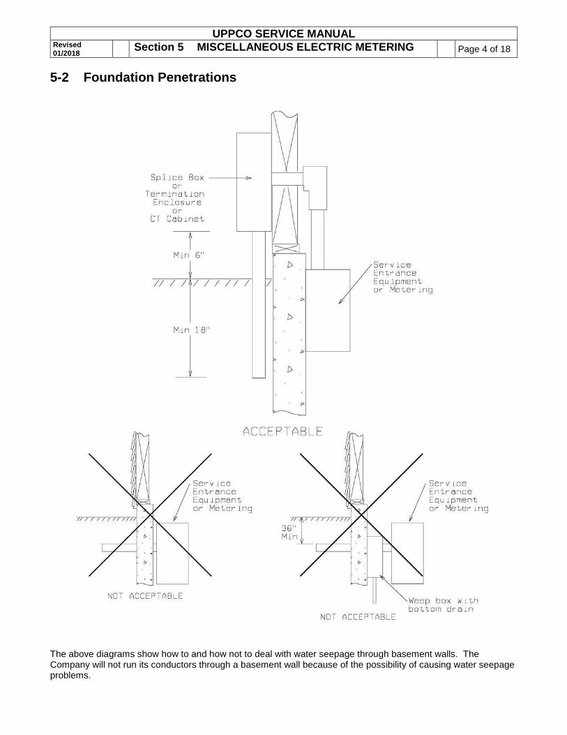
The above diagrams show how to and how not to deal with water seepage through basement walls. The Company will not run its conductors through a basement wall because of the possibility of causing water seepage problems.

UPPCO SERVICE MANUAL Revised 01/2018
Section 5 MISCELLANEOUS ELECTRIC METERING Page 5 of 18 5-3 120 Volt Meter Socket
Wired for 2-wire, 120 Volt Service This service is no longer available. This page is for reference on the old standard way of wiring this type of service.
UPPCO SERVICE MANUAL Revised 01/2018
Section 5 MISCELLANEOUS ELECTRIC METERING Page 6 of 18 5-4 Single Phase 120/208 0-200 Amp, Network Metering
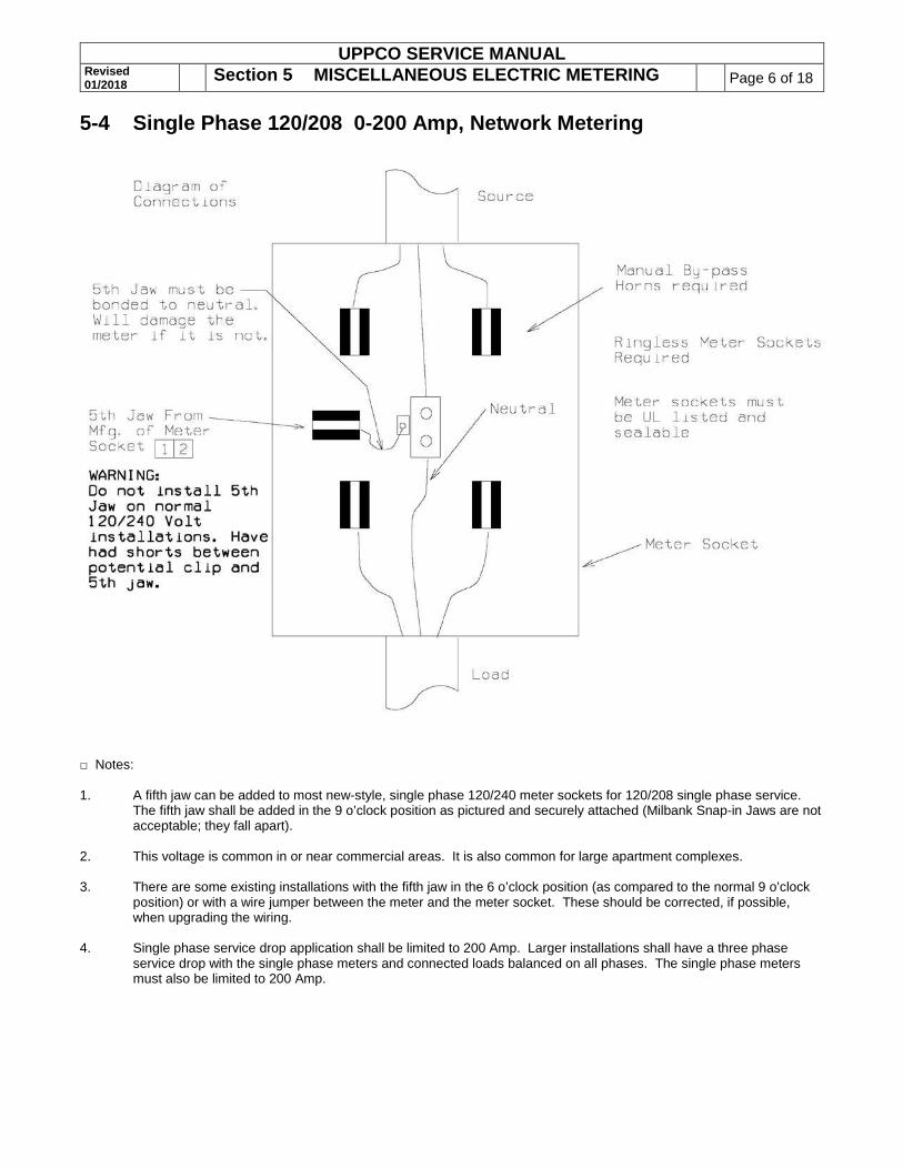
□ Notes: 1. A fifth jaw can be added to most new-style, single phase 120/240 meter sockets for 120/208 single phase service.
The fifth jaw shall be added in the 9 o’clock position as pictured and securely attached (Milbank Snap-in Jaws are not acceptable; they fall apart).
2. This voltage is common in or near commercial areas. It is also common for large apartment complexes. 3. There are some existing installations with the fifth jaw in the 6 o’clock position (as compared to the normal 9 o’clock
position) or with a wire jumper between the meter and the meter socket. These should be corrected, if possible, when upgrading the wiring.
4. Single phase service drop application shall be limited to 200 Amp. Larger installations shall have a three phase
service drop with the single phase meters and connected loads balanced on all phases. The single phase meters must also be limited to 200 Amp.

UPPCO SERVICE MANUAL Revised 01/2018
Section 5 MISCELLANEOUS ELECTRIC METERING Page 7 of 18 5-5 Multiple Metering – Indoor/Outdoor Vertical Clearances Vertical Clearances
□ Notes: 1. Metering shall be outside. 2. Service drop or lateral.
A. Underground line conductors and lugs furnished by Company. B. Load conductors and lugs furnished and installed by customer.
3. Customer shall furnish, install and maintain multiple metering equipment, including meter sockets, switches, fuses, circuit breakers, termination enclosures and associated equipment.
4. A minimum of 3 feet must be provided in front of all metering installations. See NEC 110.26(A). 5. All 100 Amp or 200 Amp meter sockets shall contain the horn-type bypass for single-phase or network installations,
be ringless, UL listed, and not have covers over the meters. 6. 6’6" OH headroom working space required per NEC 110.26(A). 7. The Company uses 90oC conductor; therefore, the Company cannot terminate on customer main disconnects (NEC
110.14). The Company can terminate in integral termination enclosures (see subsection 3-5) or separate termination enclosures (see subsection 3-7).

UPPCO SERVICE MANUAL Revised 01/2018
Section 5 MISCELLANEOUS ELECTRIC METERING Page 8 of 18 5-5 Multiple Metering – Indoor/Outdoor Vertical Clearances (Cont’d) Horizontal Clearances
□ Notes: 1. Metering shall be outside. 2. On group installations each meter socket and service switch shall be permanently marked identifying the location to
be served. The location being served shall be identified in the same manner. This identification shall be made on the outside of the metering panels (for the benefit of tenants and meter readers), inside the meter enclosure (non-movable part as cover panels usually are interchangeable), and at the service panel that the meter serves. A label on the service panel is critical because labeling systems for apartments change, making it difficult to trace. This identification is often done with permanent black markers or white paint. See NEC 110.22 and PSC 113.0809.
3. Customer shall furnish, install and maintain multiple metering equipment including meter sockets, switches, fuses, circuit breakers, termination enclosures and associated equipment.
4. A minimum of 3 feet must be provided in front of all metering installations. See NEC 110.26(A). 5. All 100 Amp or 200 Amp meter sockets shall contain the horn-type bypass for single-phase or network installations.
Installations shall have ringless meter sockets, be UL listed, be sealable, and not have covers over the meters. 6. The Company uses 90oC conductor; therefore, the Company cannot terminate their conductors on customer main
disconnects (NEC 110.14). The Company can terminate in integral termination enclosures (see subsection 3-5) or separate termination enclosures (see subsection 3-7).

UPPCO SERVICE MANUAL Revised 01/2018
Section 5 MISCELLANEOUS ELECTRIC METERING Page 9 of 18 5-5 Multiple Metering – Indoor/Outdoor Vertical Clearances (Cont’d) Swinging Door, Frontal & Side Clearances for Indoor Multiple Metering
□ Notes: 1. All new metering installations shall be outside. 2. All dimensions shown are minimum dimensions. 3. Meters are not to be installed on walls where they will be behind an open swinging door. 4. Meters may require protective barriers if traffic through doorway could cause meter damage. A minimum clearance
of 12 in. is required from the center line of the meter-connection device to the barrier. 5. Location of electric meters must comply with dimensions shown on this sketch and meter mounting height
dimensions shown on the first page of subsection 5-5. 6. A minimum of 24 inches applies when meter stacks are mounted on adjacent corner walls. 7. A minimum clearance of 3 feet must be provided in front of all metering installations. See NEC 110.26(A). 8. The Company shall be consulted concerning the location of metering equipment before metering equipment is
installed.
UPPCO SERVICE MANUAL Revised 01/2018
Section 5 MISCELLANEOUS ELECTRIC METERING Page 10 of 18
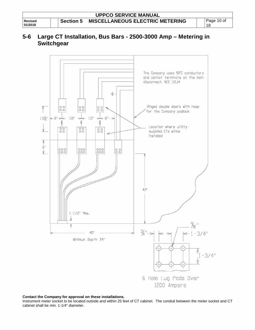
5-6 Large CT Installation, Bus Bars - 2500-3000 Amp – Metering in Switchgear
Contact the Company for approval on these installations. Instrument meter socket to be located outside and within 25 feet of CT cabinet. The conduit between the meter socket and CT cabinet shall be min. 1-1/4” diameter.

UPPCO SERVICE MANUAL Revised 01/2018
Section 5 MISCELLANEOUS ELECTRIC METERING Page 11 of 18
5-7 Large CT Installation, Doughnuts - 2500-3000 Amp – Metering in Switchgear
□ Notes: 1. Depth of current transformer compartment shall be 24" minimum. 2. CT compartment shall have hinged door and locking hasp. 3. CT mounting bracket must be adjustable for depth and height. 4. For top feed, reverse diagram configuration. 5. Customer shall furnish detailed drawings for Company approval before equipment is ordered. 6. Check with the Company to determine how many conductors per phase will be used and how many holes will be
needed on the termination pad. 7. CT’s shall be located approximately 18" below bus. 8. Bus shall be adequately braced to support conductors. 9. Instrument meter socket to be located outside and within 25 feet of CT cabinet. The conduit between shall be
minimum 1-1/4 inch.
UPPCO SERVICE MANUAL Revised 01/2018
Section 5 MISCELLANEOUS ELECTRIC METERING Page 12 of 18
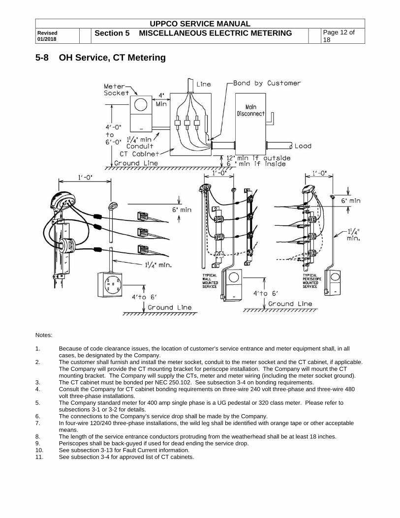
5-8 OH Service, CT Metering
Notes: 1. Because of code clearance issues, the location of customer’s service entrance and meter equipment shall, in all
cases, be designated by the Company. 2. The customer shall furnish and install the meter socket, conduit to the meter socket and the CT cabinet, if applicable.
The Company will provide the CT mounting bracket for periscope installation. The Company will mount the CT mounting bracket. The Company will supply the CTs, meter and meter wiring (including the meter socket ground).
3. The CT cabinet must be bonded per NEC 250.102. See subsection 3-4 on bonding requirements. 4. Consult the Company for CT cabinet bonding requirements on three-wire 240 volt three-phase and three-wire 480
volt three-phase installations. 5. The Company standard meter for 400 amp single phase is a UG pedestal or 320 class meter. Please refer to
subsections 3-1 or 3-2 for details. 6. The connections to the Company’s service drop shall be made by the Company. 7. In four-wire 120/240 three-phase installations, the wild leg shall be identified with orange tape or other acceptable
means. 8. The length of the service entrance conductors protruding from the weatherhead shall be at least 18 inches. 9. Periscopes shall be back-guyed if used for dead ending the service drop. 10. See subsection 3-13 for Fault Current information. 11. See subsection 3-4 for approved list of CT cabinets.

UPPCO SERVICE MANUAL Revised 01/2018
Section 5 MISCELLANEOUS ELECTRIC METERING Page 13 of 18
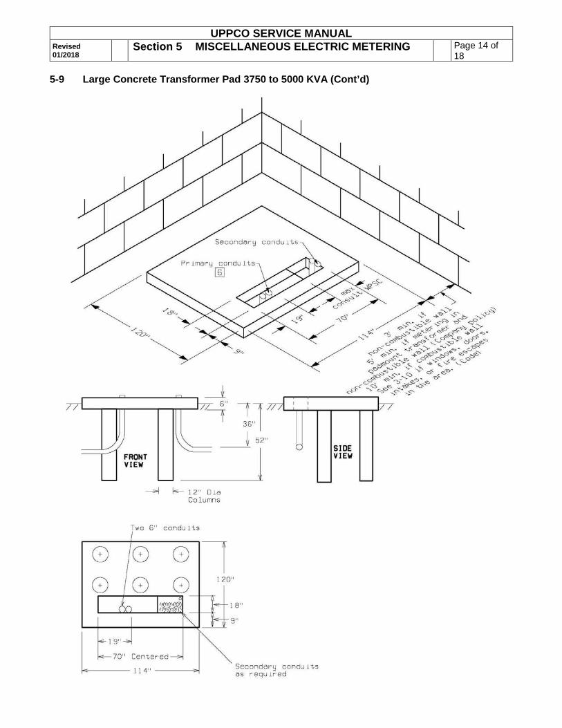
5-9 Large Concrete Transformer Pad 3750 to 5000 KVA
□ Notes: 1. Concrete shall have a minimum strength of 3000 lbs. per sq. inch and contain not less than 6 bags of cement per
cubic yard. Approximately one bag of fly ash may be substituted for one bag of cement per cubic yard of concrete. 2. The top of the pad shall be reinforced with #3 rods on a one-foot spacing. 3. These transformers range from 20,000 to 28,000 lbs. 4. Refer to subsection 3-10 for specific details on clearances from buildings. 5. Service conduits shall always start from the front right corner of the window. The conduits must be positioned tight to
the right side of the window and tight to each other and in numbered order. This is so that the conduits don’t cross over into the primary side of the transformer.
6. Position primary conduits in the front of the window and 19 inches from the left side (see top view, above). Use two each, six inch conduits.
7. 1-1/4" PVC meter conduit to building wall, if required. End this 3 inches above pad. 8. Service and Primary conduits to be just above (max. 3") pad. 9. Concrete is considered fully cured in 21 days. However, the majority of the strength is obtained after 7 days. If
transformers will be set in fewer than 7 days, cement should be tested to be sure it has at least 2500#/sq. in. of strength.
UPPCO SERVICE MANUAL Revised 01/2018
Section 5 MISCELLANEOUS ELECTRIC METERING Page 14 of 18
5-9 Large Concrete Transformer Pad 3750 to 5000 KVA (Cont’d)
UPPCO SERVICE MANUAL Revised 01/2018
Section 5 MISCELLANEOUS ELECTRIC METERING Page 15 of 18
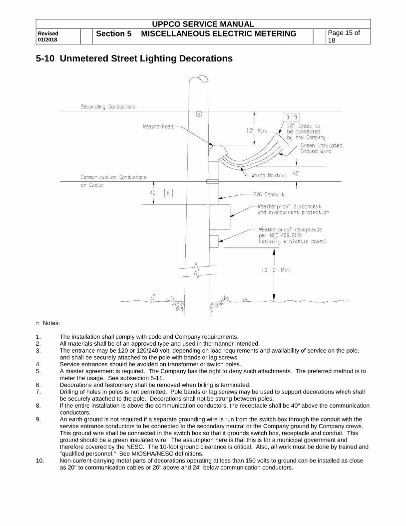
5-10 Unmetered Street Lighting Decorations
□ Notes: 1. The installation shall comply with code and Company requirements. 2. All materials shall be of an approved type and used in the manner intended. 3. The entrance may be 120 or 120/240 volt, depending on load requirements and availability of service on the pole,
and shall be securely attached to the pole with bands or lag screws. 4. Service entrances should be avoided on transformer or switch poles. 5. A master agreement is required. The Company has the right to deny such attachments. The preferred method is to
meter the usage. See subsection 5-11. 6. Decorations and festoonery shall be removed when billing is terminated. 7. Drilling of holes in poles is not permitted. Pole bands or lag screws may be used to support decorations which shall
be securely attached to the pole. Decorations shall not be strung between poles. 8. If the entire installation is above the communication conductors, the receptacle shall be 40" above the communication
conductors. 9. An earth ground is not required if a separate grounding wire is run from the switch box through the conduit with the
service entrance conductors to be connected to the secondary neutral or the Company ground by Company crews. This ground wire shall be connected in the switch box so that it grounds switch box, receptacle and conduit. This ground should be a green insulated wire. The assumption here is that this is for a municipal government and therefore covered by the NESC. The 10-foot ground clearance is critical. Also, all work must be done by trained and "qualified personnel." See MIOSHA/NESC definitions.
10. Non-current-carrying metal parts of decorations operating at less than 150 volts to ground can be installed as close as 20" to communication cables or 20" above and 24" below communication conductors.
UPPCO SERVICE MANUAL Revised 01/2018
Section 5 MISCELLANEOUS ELECTRIC METERING Page 16 of 18
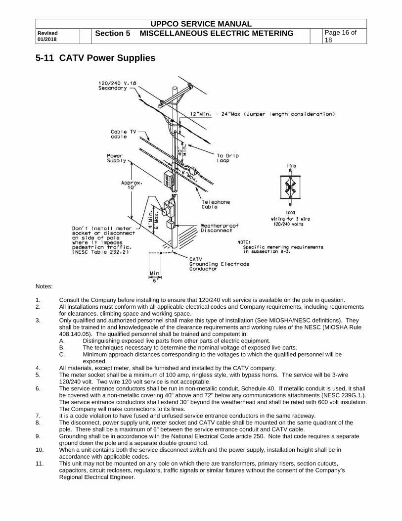
5-11 CATV Power Supplies
Notes: 1. Consult the Company before installing to ensure that 120/240 volt service is available on the pole in question. 2. All installations must conform with all applicable electrical codes and Company requirements, including requirements
for clearances, climbing space and working space. 3. Only qualified and authorized personnel shall make this type of installation (See MIOSHA/NESC definitions). They
shall be trained in and knowledgeable of the clearance requirements and working rules of the NESC (MIOSHA Rule 408.140.05). The qualified personnel shall be trained and competent in: A. Distinguishing exposed live parts from other parts of electric equipment. B. The techniques necessary to determine the nominal voltage of exposed live parts. C. Minimum approach distances corresponding to the voltages to which the qualified personnel will be
exposed. 4. All materials, except meter, shall be furnished and installed by the CATV company. 5. The meter socket shall be a minimum of 100 amp, ringless style, with bypass horns. The service will be 3-wire
120/240 volt. Two wire 120 volt service is not acceptable. 6. The service entrance conductors shall be run in non-metallic conduit, Schedule 40. If metallic conduit is used, it shall
be covered with a non-metallic covering 40" above and 72" below any communications attachments (NESC 239G.1.). The service entrance conductors shall extend 30" beyond the weatherhead and shall be rated with 600 volt insulation. The Company will make connections to its lines.
7. It is a code violation to have fused and unfused service entrance conductors in the same raceway. 8. The disconnect, power supply unit, meter socket and CATV cable shall be mounted on the same quadrant of the
pole. There shall be a maximum of 6" between the service entrance conduit and CATV cable. 9. Grounding shall be in accordance with the National Electrical Code article 250. Note that code requires a separate
ground down the pole and a separate double ground rod. 10. When a unit contains both the service disconnect switch and the power supply, installation height shall be in
accordance with applicable codes. 11. This unit may not be mounted on any pole on which there are transformers, primary risers, section cutouts,
capacitors, circuit reclosers, regulators, traffic signals or similar fixtures without the consent of the Company’s Regional Electrical Engineer.
UPPCO SERVICE MANUAL Revised 01/2018
Section 5 MISCELLANEOUS ELECTRIC METERING Page 17 of 18
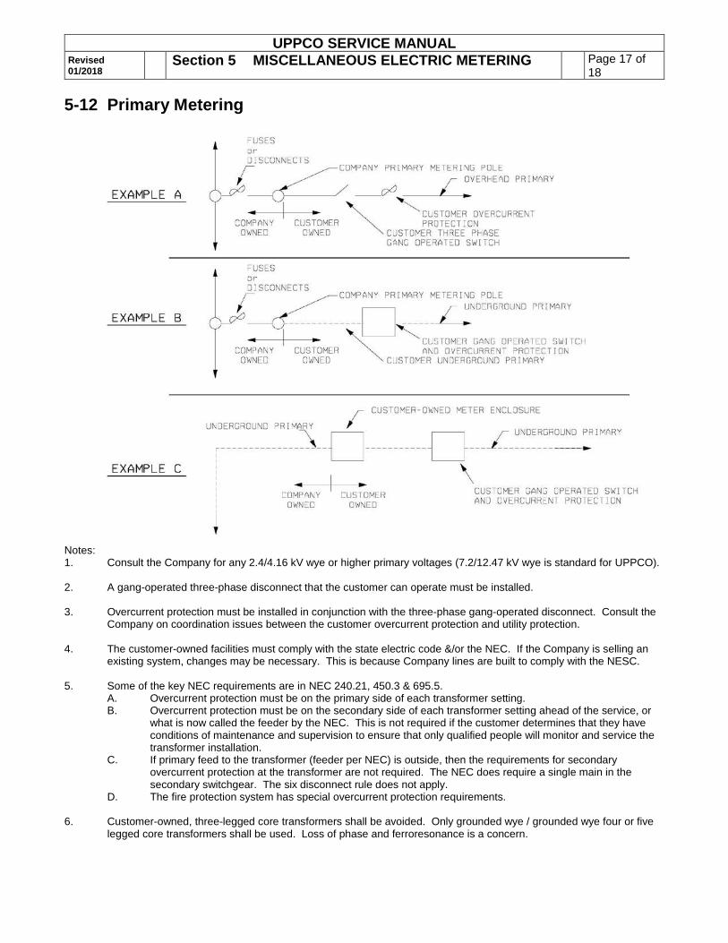
5-12 Primary Metering
Notes: 1. Consult the Company for any 2.4/4.16 kV wye or higher primary voltages (7.2/12.47 kV wye is standard for UPPCO). 2. A gang-operated three-phase disconnect that the customer can operate must be installed. 3. Overcurrent protection must be installed in conjunction with the three-phase gang-operated disconnect. Consult the
Company on coordination issues between the customer overcurrent protection and utility protection. 4. The customer-owned facilities must comply with the state electric code &/or the NEC. If the Company is selling an
existing system, changes may be necessary. This is because Company lines are built to comply with the NESC. 5. Some of the key NEC requirements are in NEC 240.21, 450.3 & 695.5.
A. Overcurrent protection must be on the primary side of each transformer setting. B. Overcurrent protection must be on the secondary side of each transformer setting ahead of the service, or
what is now called the feeder by the NEC. This is not required if the customer determines that they have conditions of maintenance and supervision to ensure that only qualified people will monitor and service the transformer installation.
C. If primary feed to the transformer (feeder per NEC) is outside, then the requirements for secondary overcurrent protection at the transformer are not required. The NEC does require a single main in the secondary switchgear. The six disconnect rule does not apply.
D. The fire protection system has special overcurrent protection requirements. 6. Customer-owned, three-legged core transformers shall be avoided. Only grounded wye / grounded wye four or five
legged core transformers shall be used. Loss of phase and ferroresonance is a concern.

UPPCO SERVICE MANUAL Revised 01/2018
Section 5 MISCELLANEOUS ELECTRIC METERING Page 18 of 18
5-13 Residential Electric Water Heater Service Entrance – Maintenance Only
FOR MAINTENANCE – NO LONGER AVAILABLE
Notes: 1. Location of entrance to be determined by the Company and coordinated with customer prior to installation. 2. If the main service disconnect is grounded to the water supply line, then a minimum 10 AWG ground wire must be
installed between the water heater disconnect panel and the main service panel.