Embed Size (px)
Citation preview
ESE 471 – Energy Storage Systems
SECTION 3: PUMPED-HYDRO ENERGY STORAGE
K. Webb ESE 471
Introduction2

K. Webb ESE 471
3
Potential Energy Storage
Energy can be stored as potential energy Consider a mass, 𝑚𝑚, elevated to a height, ℎ Its potential energy increase is
𝐸𝐸 = 𝑚𝑚𝑚𝑚ℎ
where 𝑚𝑚 = 9.81 𝑚𝑚/𝑠𝑠2 is gravitational acceleration
Lifting the mass requires an input of work equal to (at least) the energy increase of the mass We put energy in to lift the mass That energy is stored in the mass as potential energy

K. Webb ESE 471
4
Potential Energy Storage
If we allow the mass to fall back to its original height, we can capture the stored potential energy Potential energy converted to kinetic
energy as the mass falls Kinetic energy can be captured to perform
work Perhaps converted to rotational energy,
and then to electrical energy
K. Webb ESE 471
5
Pumped-Hydro Energy Storage
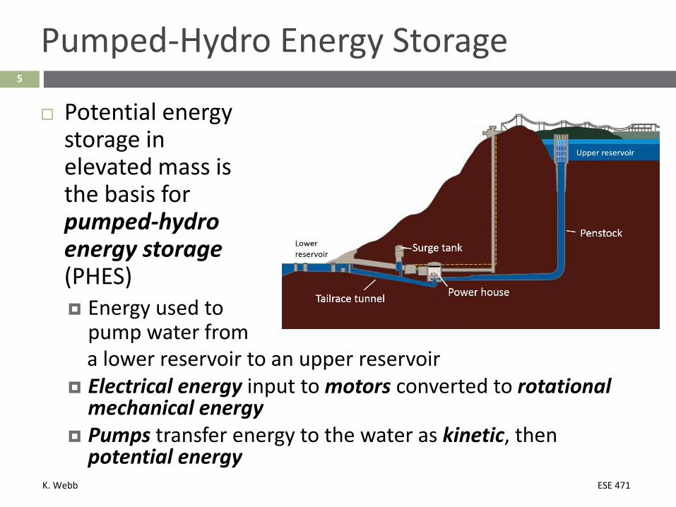
Potential energy storage in elevated mass is the basis for pumped-hydro energy storage (PHES) Energy used to
pump water froma lower reservoir to an upper reservoir
Electrical energy input to motors converted to rotational mechanical energy
Pumps transfer energy to the water as kinetic, then potential energy
K. Webb ESE 471
6
Pumped-Hydro Energy Storage
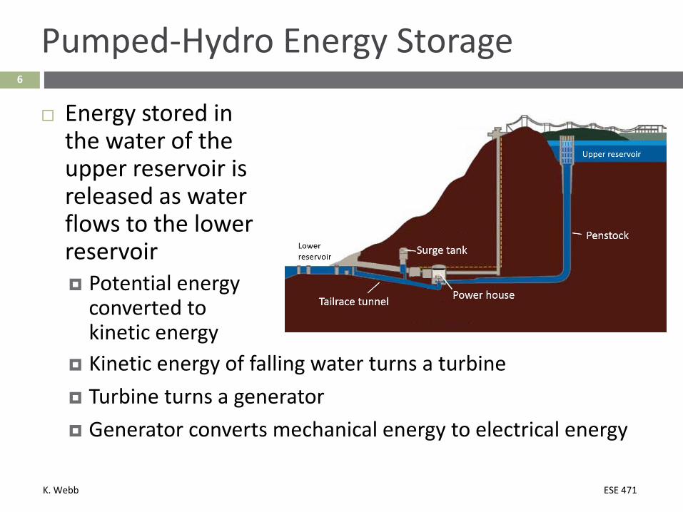
Energy stored in the water of the upper reservoir is released as water flows to the lower reservoir Potential energy
converted to kinetic energy
Kinetic energy of falling water turns a turbine Turbine turns a generator Generator converts mechanical energy to electrical energy
K. Webb ESE 471
7
History of PHES
PHES first introduced in Italy and Switzerland in the 1890’s Favorable topography in the Alps Four-unit (quaternary) systems Turbine GeneratorMotor Pump

K. Webb ESE 471
8
History of PHES
First PHES plant in the US: Rocky River hydro plant,
New Milford, CT Water from the Housatonic
River pumped up into Candlewood Lake
230 feet of head 6 billion ft3 of water Two-unit (binary) system Reversible pump/turbine –
one of the first 29 MW of generating power
K. Webb ESE 471
9
Pumped-Hydro Storage Today
PHES accounts for 99% of worldwide energy storage Total power: ~127 GW Total energy: ~740 TWh Power of individual plants: 10s of MW – 3 GW
In the US: ~40 operational PHES plants 75% are > 500 MW – strong economies of scale Total power: ~23 GW Current plans for an additional ~6 GW
Total energy: ~220 TWh
K. Webb ESE 471
PHES Fundamentals10
K. Webb ESE 471
11
PHES Fundamentals
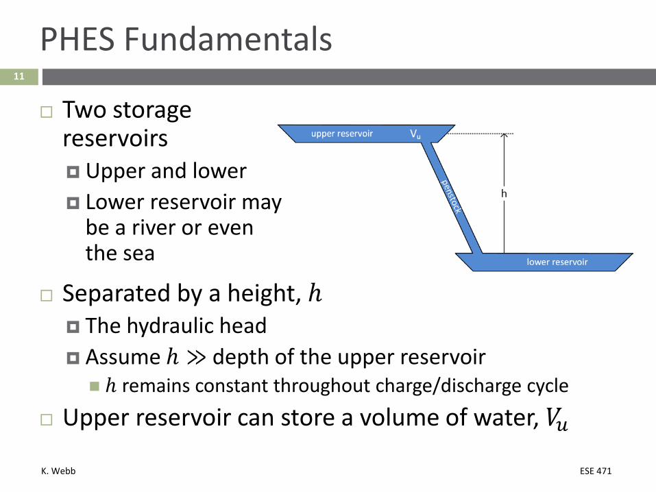
Two storage reservoirs Upper and lower Lower reservoir may
be a river or even the sea
Separated by a height, ℎ The hydraulic head Assume ℎ ≫ depth of the upper reservoir ℎ remains constant throughout charge/discharge cycle
Upper reservoir can store a volume of water, 𝑉𝑉𝑢𝑢
K. Webb ESE 471
12
PHES Fundamentals - Energy
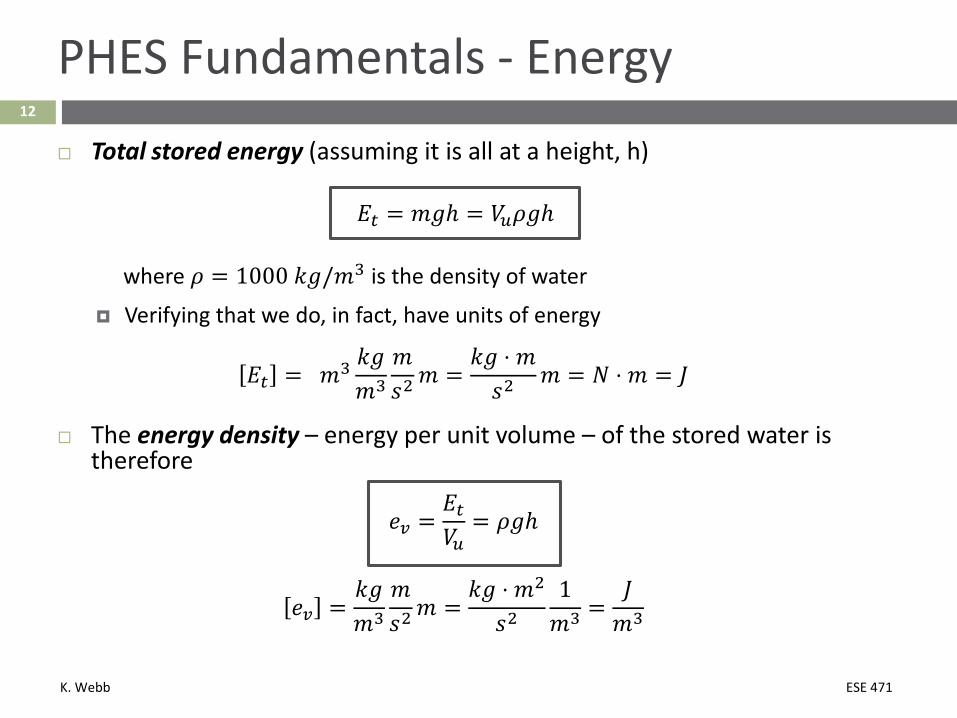
Total stored energy (assuming it is all at a height, h)
𝐸𝐸𝑡𝑡 = 𝑚𝑚𝑚𝑚ℎ = 𝑉𝑉𝑢𝑢𝜌𝜌𝑚𝑚ℎ
where 𝜌𝜌 = 1000 𝑘𝑘𝑚𝑚/𝑚𝑚3 is the density of water
Verifying that we do, in fact, have units of energy
𝐸𝐸𝑡𝑡 = 𝑚𝑚3 𝑘𝑘𝑚𝑚𝑚𝑚3
𝑚𝑚𝑠𝑠2 𝑚𝑚 =
𝑘𝑘𝑚𝑚 ⋅ 𝑚𝑚𝑠𝑠2 𝑚𝑚 = 𝑁𝑁 ⋅ 𝑚𝑚 = 𝐽𝐽
The energy density – energy per unit volume – of the stored water is therefore
𝑒𝑒𝑣𝑣 =𝐸𝐸𝑡𝑡𝑉𝑉𝑢𝑢
= 𝜌𝜌𝑚𝑚ℎ
𝑒𝑒𝑣𝑣 =𝑘𝑘𝑚𝑚𝑚𝑚3
𝑚𝑚𝑠𝑠2 𝑚𝑚 =
𝑘𝑘𝑚𝑚 ⋅ 𝑚𝑚2
𝑠𝑠21𝑚𝑚3 =
𝐽𝐽𝑚𝑚3

K. Webb ESE 471
13
PHES Fundamentals – Hydrostatic Pressure
The energy density of the stored water is also the hydrostatic pressure at the level of the lower reservoir
𝑝𝑝 = 𝜌𝜌𝑚𝑚ℎ
𝑝𝑝 =𝑘𝑘𝑚𝑚𝑚𝑚3
𝑚𝑚𝑠𝑠2𝑚𝑚 =
𝑘𝑘𝑚𝑚 ⋅ 𝑚𝑚𝑠𝑠2
1𝑚𝑚2 =
𝑁𝑁𝑚𝑚2 = 𝑃𝑃𝑃𝑃
This is the energy density of the water at the turbine
K. Webb ESE 471
14
PHES Fundamentals - Power
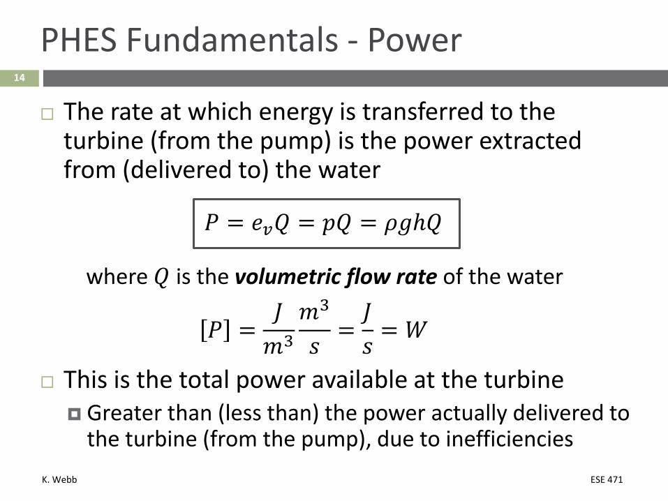
The rate at which energy is transferred to the turbine (from the pump) is the power extracted from (delivered to) the water
𝑃𝑃 = 𝑒𝑒𝑣𝑣𝑄𝑄 = 𝑝𝑝𝑄𝑄 = 𝜌𝜌𝑚𝑚ℎ𝑄𝑄
where 𝑄𝑄 is the volumetric flow rate of the water
𝑃𝑃 =𝐽𝐽𝑚𝑚3
𝑚𝑚3
𝑠𝑠=𝐽𝐽𝑠𝑠
= 𝑊𝑊
This is the total power available at the turbine Greater than (less than) the power actually delivered to
the turbine (from the pump), due to inefficiencies

K. Webb ESE 471
15
A Generalized Power Relation
Note that power is given by the product of a driving potential, or effort, 𝑝𝑝, and a flow, 𝑄𝑄
𝑃𝑃 = 𝑝𝑝𝑄𝑄
Similar to power for a translational mechanical system𝑃𝑃 = 𝐹𝐹𝐹𝐹
where the effort is force, 𝐹𝐹, and the flow is velocity, 𝐹𝐹
Or, a rotational mechanical system𝑃𝑃 = 𝜏𝜏𝜏𝜏
where the effort is torque, 𝜏𝜏, and the flow is angular velocity, 𝐹𝐹

K. Webb ESE 471
16
A Generalized Power Relation
Also similar to an electrical system
𝑃𝑃 = 𝑉𝑉𝑉𝑉
where the effort is voltage, 𝑉𝑉, and the flow is current, 𝑉𝑉
In general, for systems in any energy domain, power is given by the product of effort and flow
𝑃𝑃 = 𝑒𝑒 ⋅ 𝑓𝑓
K. Webb ESE 471
17
Energy & Power vs. Head
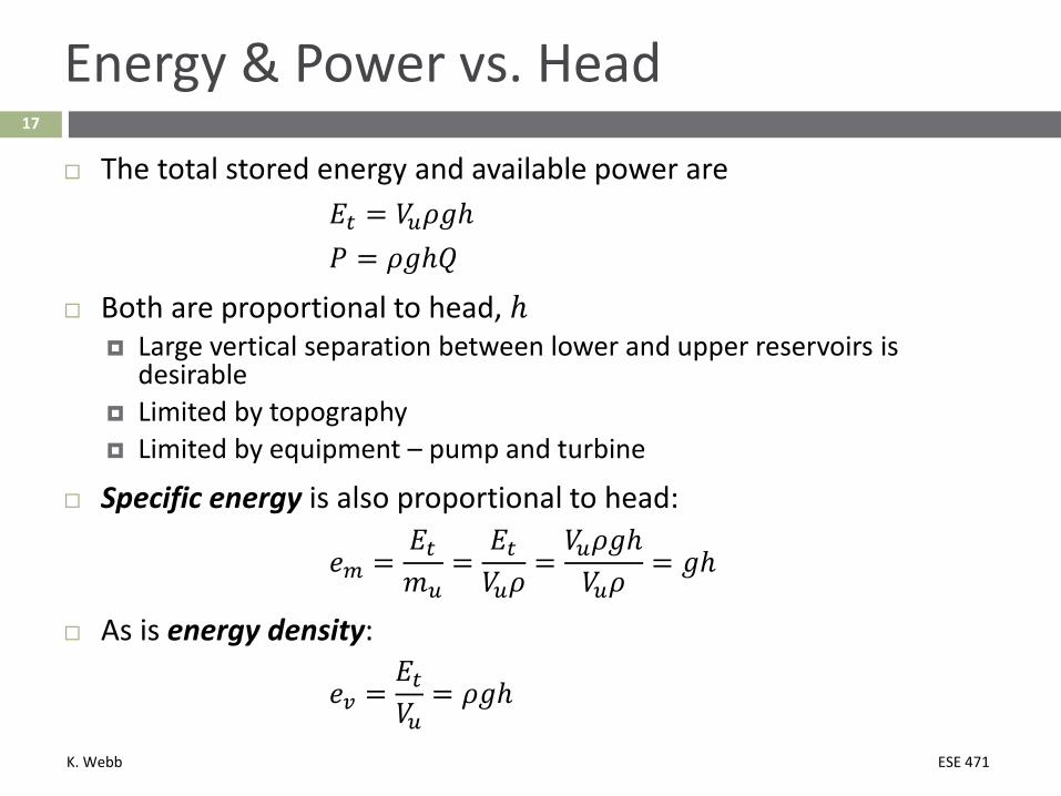
The total stored energy and available power are𝐸𝐸𝑡𝑡 = 𝑉𝑉𝑢𝑢𝜌𝜌𝑚𝑚ℎ𝑃𝑃 = 𝜌𝜌𝑚𝑚ℎ𝑄𝑄
Both are proportional to head, ℎ Large vertical separation between lower and upper reservoirs is
desirable Limited by topography Limited by equipment – pump and turbine
Specific energy is also proportional to head:
𝑒𝑒𝑚𝑚 =𝐸𝐸𝑡𝑡𝑚𝑚𝑢𝑢
=𝐸𝐸𝑡𝑡𝑉𝑉𝑢𝑢𝜌𝜌
=𝑉𝑉𝑢𝑢𝜌𝜌𝑚𝑚ℎ𝑉𝑉𝑢𝑢𝜌𝜌
= 𝑚𝑚ℎ
As is energy density:
𝑒𝑒𝑣𝑣 =𝐸𝐸𝑡𝑡𝑉𝑉𝑢𝑢
= 𝜌𝜌𝑚𝑚ℎ

K. Webb ESE 471
18
Specific Energy & Energy Density vs. Head
Most PHES plants have head in the range of 100 – 1000 m Using 300 m as a representative head, gives:
Energy density for 𝒉𝒉 = 𝟑𝟑𝟑𝟑𝟑𝟑𝒎𝒎:
𝑒𝑒𝑣𝑣 = 𝜌𝜌𝑚𝑚ℎ = 1000𝑘𝑘𝑚𝑚𝑚𝑚3 ⋅ 9.81
𝑚𝑚𝑠𝑠2⋅ 300 𝑚𝑚
𝑒𝑒𝑣𝑣 = 2.9𝑀𝑀𝐽𝐽𝑚𝑚3 ⋅
13600
𝑊𝑊ℎ𝐽𝐽 = 𝟖𝟖𝟖𝟖𝟖𝟖
𝑾𝑾𝒉𝒉𝒎𝒎𝟑𝟑
𝑒𝑒𝑣𝑣 = 818𝑊𝑊ℎ𝑚𝑚3 ⋅ 1
𝑚𝑚3
1000 𝐿𝐿 = 𝟑𝟑.𝟖𝟖𝟖𝟖𝟖𝟖𝑾𝑾𝒉𝒉𝑳𝑳
Specific energy for 𝒉𝒉 = 𝟑𝟑𝟑𝟑𝟑𝟑𝒎𝒎:
𝑒𝑒𝑚𝑚 = 𝑚𝑚ℎ = 9.81𝑚𝑚𝑠𝑠2 ⋅ 300 𝑚𝑚 = 4905
𝑚𝑚2
𝑠𝑠2 = 2.9𝑘𝑘𝐽𝐽𝑘𝑘𝑚𝑚
𝑒𝑒𝑚𝑚 = 2.9𝑘𝑘𝐽𝐽𝑘𝑘𝑚𝑚 ⋅
13600
𝑊𝑊ℎ𝐽𝐽 = 𝟑𝟑.𝟖𝟖𝟖𝟖𝟖𝟖
𝑾𝑾𝒉𝒉𝒌𝒌𝒌𝒌

K. Webb ESE 471
19
Specific Energy & Energy Density
Comparison of PHES energy density and specific energy with other energy storage/sources
PHESh = 100 m
PHESh = 500 m
PHESh = 1000m
Li-ion Battery
Natural Gas Gasoline Units
Energy Density 0.273 1.36 2.73 400 10.1 9,500 Wh/L
Specific Energy 0.273 1.36 2.73 150 15,400 13,000 Wh/kg
Even at high heads, PHES has very low energy density Large reservoirs are required

K. Webb ESE 471
20
PHES Applications
Pumped hydro plants can supply large amounts of both power and energy
Can quickly respond to large load variations Uses for PHES:
Peak shaving/load leveling Help meet loads during peak hours Generating while releasing water from upper reservoir Supplying expensive energy
Store energy during off-peak hours Pumping water to the upper reservoir Consuming inexpensive energy

K. Webb ESE 471
21
PHES Applications
Frequency regulation Power variation to track short-term load variations Helps maintain grid frequency at 60 Hz (50 Hz)
Voltage support Reactive power flow control to help maintain desired
grid voltage Varying the field excitation voltage of the generator/motor
Even at zero real power – not pumping or generating –unloaded motor/generator can serve as synchronous condenser Pump/turbine spinning in air
K. Webb ESE 471
22
PHES Applications
Black start capability Ability to start generating without an external power
supply Bring the grid back online after a blackout
Spinning reserve Spare online generating capacity Capable of responding quickly – within seconds to
minutes – to the need for additional generation

K. Webb ESE 471
Components of a PHES Plant23

K. Webb ESE 471
24
Components of a PHES Plant
K. Webb ESE 471
25
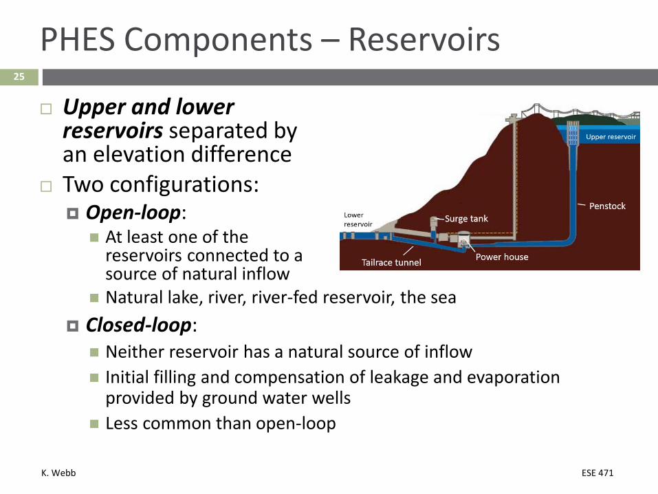
PHES Components – Reservoirs
Upper and lower reservoirs separated by an elevation difference
Two configurations: Open-loop: At least one of the
reservoirs connected to a source of natural inflow
Natural lake, river, river-fed reservoir, the sea Closed-loop: Neither reservoir has a natural source of inflow Initial filling and compensation of leakage and evaporation
provided by ground water wells Less common than open-loop

K. Webb ESE 471
26
PHES Components – Penstock
Penstock Conduit for water flowing
between reservoirs and to the pump/generator
Above-ground pipes or below ground shafts/tunnels 5 -10 m diameter is common One plant may have several penstocks Typically steel- or concrete-lined, though may be unlined
Flow velocity range of 1 – 5 m/s is common Tradeoff between cost and efficiency for a given flow rate, 𝑄𝑄 Larger cross-sectional area:
Slower flow Lower loss Higher cost

K. Webb ESE 471
27
PHES Components
Tailrace tunnel Typically, larger diameter
than penstocks Lower pressure Lower flow rate Downward slope from lower
reservoir to pump/turbine Inlet head helps prevent
cavitation in pumping mode
Surge tanks Accumulator tanks to absorb high pressure transients during
startup and mode changeover May be located on penstock or tailrace Especially important for longer tunnels Hydraulic bypass capacitors

K. Webb ESE 471
28
PHES Components – Power House
Power house Contains pump/turbines
and motor/generators Often underground Typically below the level
of the lower reservoir to provide required pump inlet head
Three possible configurations Binary set: one pump/turbine and one motor/generator Ternary set: one pump, one turbine, and one motor/generator Quaternary set: separate pump, turbine, motor, and generator
K. Webb ESE 471
Power Plant Configurations29
K. Webb ESE 471
30
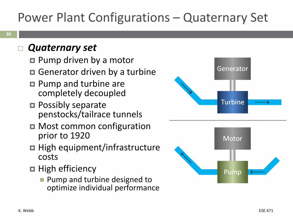
Power Plant Configurations – Quaternary Set
Quaternary set Pump driven by a motor Generator driven by a turbine Pump and turbine are
completely decoupled Possibly separate
penstocks/tailrace tunnels Most common configuration
prior to 1920 High equipment/infrastructure
costs High efficiency Pump and turbine designed to
optimize individual performance
K. Webb ESE 471
31
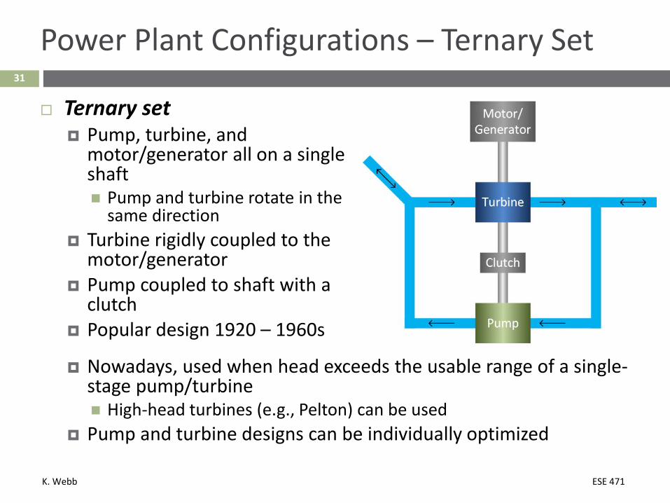
Power Plant Configurations – Ternary Set
Ternary set Pump, turbine, and
motor/generator all on a single shaft Pump and turbine rotate in the
same direction Turbine rigidly coupled to the
motor/generator Pump coupled to shaft with a
clutch Popular design 1920 – 1960s
Nowadays, used when head exceeds the usable range of a single-stage pump/turbine High-head turbines (e.g., Pelton) can be used
Pump and turbine designs can be individually optimized

K. Webb ESE 471
32
Power Plant Configurations – Ternary Set
Ternary set Generating mode: Turbine spins generator Pump decoupled from the shaft
and isolated with valves Pumping mode: Motor turns the pump Turbine spins in air, isolated with
valves Both turbine and pump can
operate simultaneously Turbine can be used for pump startup Both spin in the same direction Turbine brings pump up to speed and synchronized with grid, then
shuts down Changeover time reduced

K. Webb ESE 471
33
Power Plant Configurations – Binary Set
Binary set Single reversible
pump/turbine coupled to a single motor/generator
Most popular configuration for modern PHES
Lowest cost configuration Less equipment Simplified hydraulic pathways Fewer valves, gates, controls, etc.
Lower efficiency than for ternary or quaternary sets Pump/turbine runner design is a compromise between pump and
turbine performance
K. Webb ESE 471
34
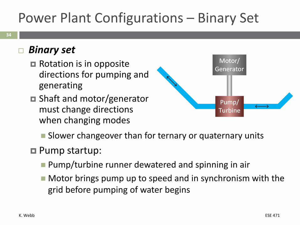
Power Plant Configurations – Binary Set
Binary set Rotation is in opposite
directions for pumping and generating
Shaft and motor/generator must change directions when changing modes Slower changeover than for ternary or quaternary units
Pump startup: Pump/turbine runner dewatered and spinning in airMotor brings pump up to speed and in synchronism with the
grid before pumping of water begins

K. Webb ESE 471
Turbines35
K. Webb ESE 471
36
Turbines
Hydro turbine design selection based on Head Flow rate
PHES plants are typically sited to have large head Energy density is proportional to head Typically 100s of meters
Reversible Francis pump/turbine Most common turbine for PHES applications Single-stage pump/turbines operate with heads up to 700 m
For higher head: Multi-stage pump/turbines Ternary units with Pelton turbines
K. Webb ESE 471
37
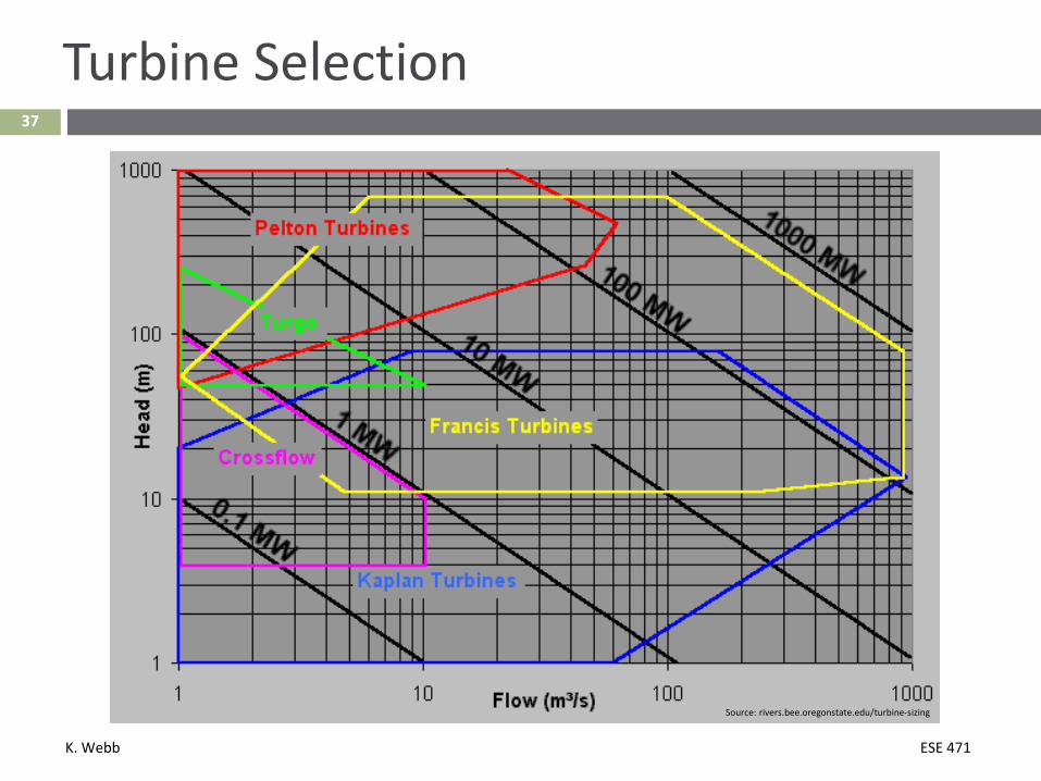
Turbine Selection
Source: rivers.bee.oregonstate.edu/turbine-sizing
K. Webb ESE 471
38
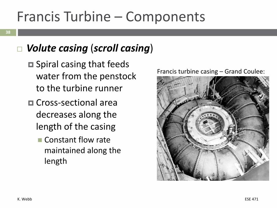
Francis Turbine – Components
Spiral casing that feeds water from the penstock to the turbine runner
Cross-sectional area decreases along the length of the casing Constant flow rate
maintained along the length
Volute casing (scroll casing)
Francis turbine casing – Grand Coulee:
K. Webb ESE 471
39
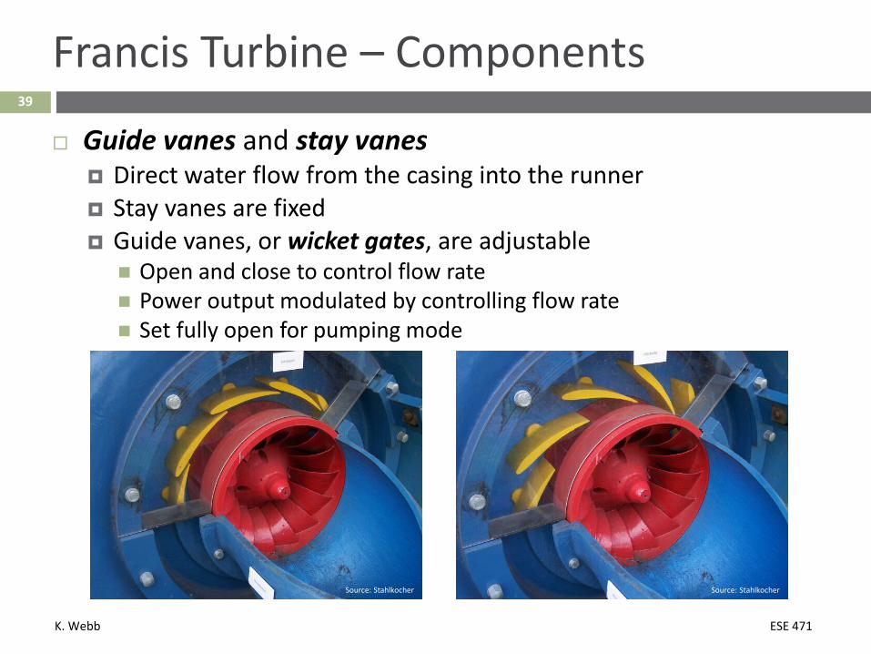
Francis Turbine – Components
Guide vanes and stay vanes Direct water flow from the casing into the runner Stay vanes are fixed Guide vanes, or wicket gates, are adjustable Open and close to control flow rate Power output modulated by controlling flow rate Set fully open for pumping mode
Source: Stahlkocher Source: Stahlkocher
K. Webb ESE 471
40
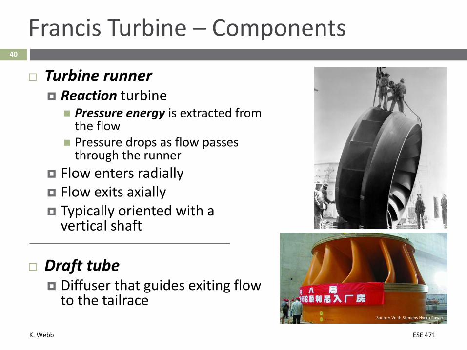
Francis Turbine – Components
Turbine runner Reaction turbine Pressure energy is extracted from
the flow Pressure drops as flow passes
through the runner Flow enters radially Flow exits axially Typically oriented with a
vertical shaft
Draft tube Diffuser that guides exiting flow
to the tailraceSource: Voith Siemens Hydro Power
K. Webb ESE 471
41
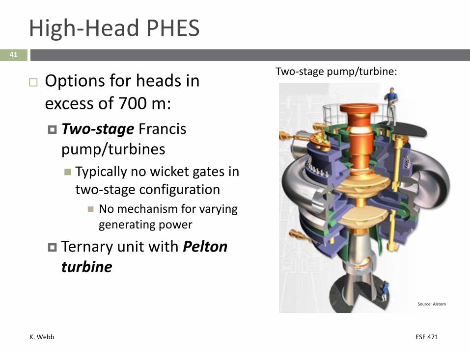
High-Head PHES
Options for heads in excess of 700 m: Two-stage Francis
pump/turbines Typically no wicket gates in
two-stage configuration No mechanism for varying
generating power
Ternary unit with Pelton turbine
Two-stage pump/turbine:
Source: Alstom

K. Webb ESE 471
42
Pelton Turbines
Pelton Turbine Suitable for heads up to 1000 m Impulse turbine Nozzles convert pressure energy to kinetic
energy High-velocity jets impinge on the runner at
atmospheric pressure
Source: Alstom
Source: BFL Hydro Power
Kinetic energy transferred to the runner
Water exits the turbine at low velocity
Cannot be used for pumping Used as part of a
ternary set
K. Webb ESE 471
Motor/Generator43

K. Webb ESE 471
44
Motor/Generator – Fixed-Speed
Pump/turbine shaft connects to a motor/generator unit Above the turbine runner in typical vertical configuration
Motor/generator type depends PHES category: Fixed-speed pump/turbine Variable-speed pump/turbine
Fixed-speed pump/turbine Motor/generator operates at a fixed speed in both pumping
and generating modes Synchronous motor/generator Rotation is synchronous with the AC grid frequency Stator windings connect to three-phase AC at grid frequency Rotor windings fed with DC excitation current via slip rings DC excitation current generated with thyristor AC/DC converters

K. Webb ESE 471
45
Motor/Generator
Variable-speed (adjustable-speed) pump/turbine Rotational speed of motor/generator is adjustable Two options:
Variable speed using a synchronous motor/generator (singly-fed) Doubly-fed asynchronous machine (DFAM)
Variable-speed operation with synchronous motor/generator:
Motor driven with variable frequency Decoupled from grid frequency by back-to-back converters Converters must be rated for full motor/generator power
Large, expensive

K. Webb ESE 471
46
Motor/Generator – Variable-Speed
Variable speed using doubly-fed asynchronous machines Field excitation fed with variable, low-frequency AC, not DC as in
synchronous machines Static frequency converter generates variable AC
Cycloconverter Back-to-back voltage-source converters
Typically small speed range (e.g., ±10%) With cycloconverter generating variable-frequency excitation for
rotor:
Converters need not be sized for rated motor/generator power Only supply lower-power excitation to the rotor

K. Webb ESE 471
47
Motor/Generator – Variable-Speed
DFAM with variable-frequency field excitation generated by back-to-back VSCs:
The preferred configuration for large (>100 MW) PHES plants nowadays
Advantages of variable-speed plants Pump and turbine speeds can be independently varied to
optimize efficiency over range of flow rate and head Pumping power can be varied in addition to generating power
K. Webb ESE 471
48
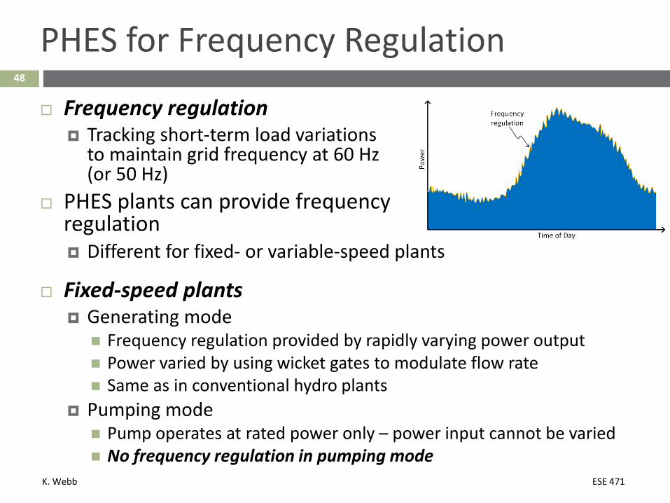
PHES for Frequency Regulation
Frequency regulation Tracking short-term load variations
to maintain grid frequency at 60 Hz (or 50 Hz)
PHES plants can provide frequency regulation Different for fixed- or variable-speed plants
Fixed-speed plants Generating mode Frequency regulation provided by rapidly varying power output Power varied by using wicket gates to modulate flow rate Same as in conventional hydro plants
Pumping mode Pump operates at rated power only – power input cannot be varied No frequency regulation in pumping mode
K. Webb ESE 471
49
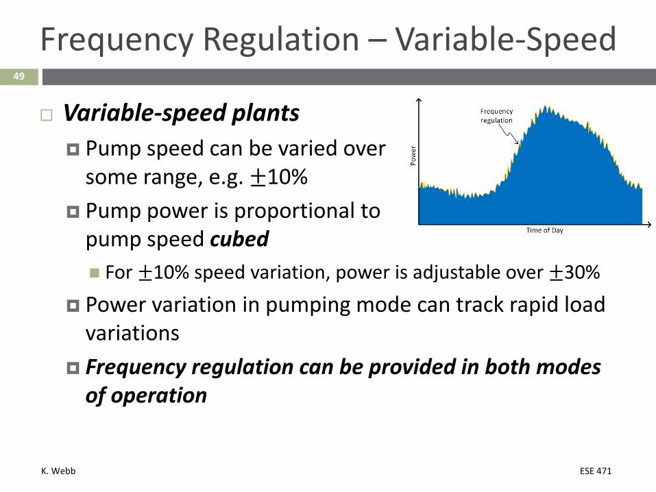
Frequency Regulation – Variable-Speed
Variable-speed plants Pump speed can be varied over
some range, e.g. ±10% Pump power is proportional to
pump speed cubed For ±10% speed variation, power is adjustable over ±30%
Power variation in pumping mode can track rapid load variations
Frequency regulation can be provided in both modes of operation
K. Webb ESE 471
50
Frequency Regulation – Ternary Sets
Fixed-speed ternary sets Generating modeWicket gates in turbine control flow rate to vary power
output Pump disconnected from shaft
Pumping mode Hydraulic short circuit provides power modulation Pump and generator both turn on the shaft Pump operates at full load Generator operates at variable partial load

K. Webb ESE 471
51
Hydraulic Short Circuit
Kops II PHES plant in Austrian Alps:
Source: Vorarlberger Illvwerke AG
K. Webb ESE 471
PHES Efficiency52
K. Webb ESE 471
53
PHES System Efficiency
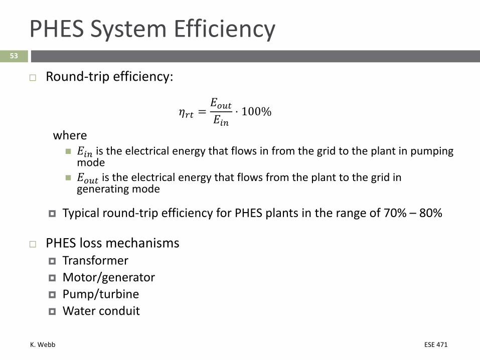
Round-trip efficiency:
𝜂𝜂𝑟𝑟𝑡𝑡 =𝐸𝐸𝑜𝑜𝑢𝑢𝑡𝑡𝐸𝐸𝑖𝑖𝑖𝑖
⋅ 100%
where 𝐸𝐸𝑖𝑖𝑖𝑖 is the electrical energy that flows in from the grid to the plant in pumping
mode 𝐸𝐸𝑜𝑜𝑢𝑢𝑡𝑡 is the electrical energy that flows from the plant to the grid in
generating mode
Typical round-trip efficiency for PHES plants in the range of 70% – 80%
PHES loss mechanisms Transformer Motor/generator Pump/turbine Water conduit

K. Webb ESE 471
54
PHES Losses
Transformers Pumped hydro plants connect to the AC electrical grid Transformers step voltage between high voltage on the grid side
to lower voltage at the motor/generator
Transformer loss mechanisms: Winding resistance Leakage flux Hysteresis and eddy currents in the core Magnetizing current – finite core permeability
Power flows through transformers on the way into the storage plant and again on the way out
Typical loss: ~0.5%
K. Webb ESE 471
55
PHES Losses
Motor/generator losses Electrical resistance Mechanical friction Typical loss: ~2%
Pump/turbine Single runner in binary sets Typically lower efficiency, particularly for fixed-speed
operation – design of both compromised Separate runners in ternary, quaternary sets Higher efficiency
Typical loss: ~7% - 10%
K. Webb ESE 471
56
PHES Losses
Penstock Frictional loss of water flowing through the conduit Major losses along penstock Minor losses from bends, penstock inlet, turbine inlet, etc.
Dependent on Flow velocity Penstock diameter Penstock length Penstock lining – steel, concrete, etc.
High head is desirable, but long penstocks are not Steeper penstocks reduce frictional losses for a given head Typical length-to-head ratio: 4:1 – 12:1
Typical loss: ~1%
K. Webb ESE 471
57
PHES Losses
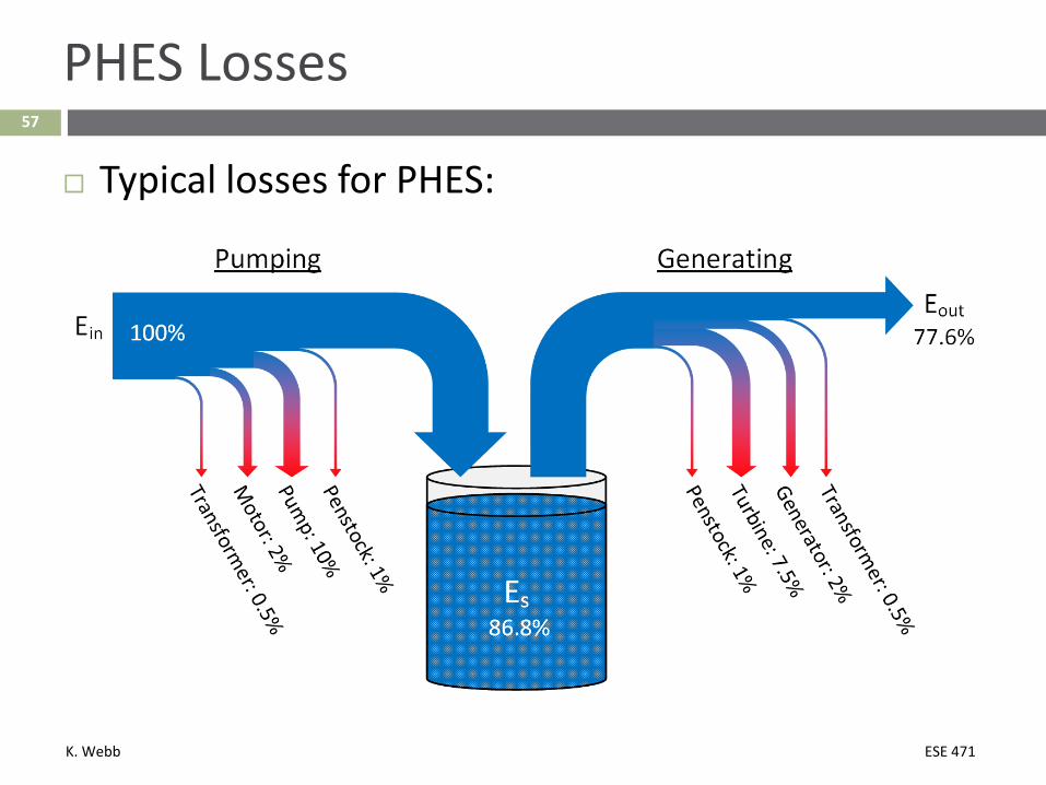
Typical losses for PHES:

K. Webb ESE 471
58
Pumping-Mode Efficiency
Efficiency of the pumping operation is given by
𝜂𝜂𝑝𝑝 =𝐸𝐸𝑠𝑠𝐸𝐸𝑖𝑖𝑖𝑖
⋅ 100%
where 𝐸𝐸𝑠𝑠 is the energy stored
Potential energy of the volume of water, 𝑉𝑉𝑢𝑢, pumped to the upper reservoir
𝐸𝐸𝑠𝑠 = 𝑉𝑉𝑢𝑢𝜌𝜌𝑚𝑚ℎ
𝐸𝐸𝑖𝑖𝑖𝑖 is the energy input from the grid during the pumping operation The mechanical energy input to the pump is
𝐸𝐸𝑖𝑖𝑖𝑖,𝑝𝑝𝑢𝑢𝑚𝑚𝑝𝑝 = 𝐸𝐸𝑖𝑖𝑖𝑖 ⋅ 𝜂𝜂𝑡𝑡𝑟𝑟𝑡𝑡𝑖𝑖𝑠𝑠 ⋅ 𝜂𝜂𝑚𝑚𝑜𝑜𝑡𝑡𝑜𝑜𝑟𝑟where 𝜂𝜂𝑡𝑡𝑟𝑟𝑡𝑡𝑖𝑖𝑠𝑠 and 𝜂𝜂𝑚𝑚𝑜𝑜𝑡𝑡𝑜𝑜𝑟𝑟 are the efficiencies of the transformer and motor,
respectively
K. Webb ESE 471
59
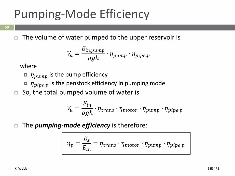
Pumping-Mode Efficiency
The volume of water pumped to the upper reservoir is
𝑉𝑉𝑢𝑢 =𝐸𝐸𝑖𝑖𝑖𝑖,𝑝𝑝𝑢𝑢𝑚𝑚𝑝𝑝
𝜌𝜌𝑚𝑚ℎ⋅ 𝜂𝜂𝑝𝑝𝑢𝑢𝑚𝑚𝑝𝑝 ⋅ 𝜂𝜂𝑝𝑝𝑖𝑖𝑝𝑝𝑝𝑝,𝑝𝑝
where 𝜂𝜂𝑝𝑝𝑢𝑢𝑚𝑚𝑝𝑝 is the pump efficiency 𝜂𝜂𝑝𝑝𝑖𝑖𝑝𝑝𝑝𝑝,𝑝𝑝 is the penstock efficiency in pumping mode
So, the total pumped volume of water is
𝑉𝑉𝑢𝑢 =𝐸𝐸𝑖𝑖𝑖𝑖𝜌𝜌𝑚𝑚ℎ
⋅ 𝜂𝜂𝑡𝑡𝑟𝑟𝑡𝑡𝑖𝑖𝑠𝑠 ⋅ 𝜂𝜂𝑚𝑚𝑜𝑜𝑡𝑡𝑜𝑜𝑟𝑟 ⋅ 𝜂𝜂𝑝𝑝𝑢𝑢𝑚𝑚𝑝𝑝 ⋅ 𝜂𝜂𝑝𝑝𝑖𝑖𝑝𝑝𝑝𝑝,𝑝𝑝
The pumping-mode efficiency is therefore:
𝜂𝜂𝑝𝑝 =𝐸𝐸𝑠𝑠𝐸𝐸𝑖𝑖𝑖𝑖
= 𝜂𝜂𝑡𝑡𝑟𝑟𝑡𝑡𝑖𝑖𝑠𝑠 ⋅ 𝜂𝜂𝑚𝑚𝑜𝑜𝑡𝑡𝑜𝑜𝑟𝑟 ⋅ 𝜂𝜂𝑝𝑝𝑢𝑢𝑚𝑚𝑝𝑝 ⋅ 𝜂𝜂𝑝𝑝𝑖𝑖𝑝𝑝𝑝𝑝,𝑝𝑝
K. Webb ESE 471
60
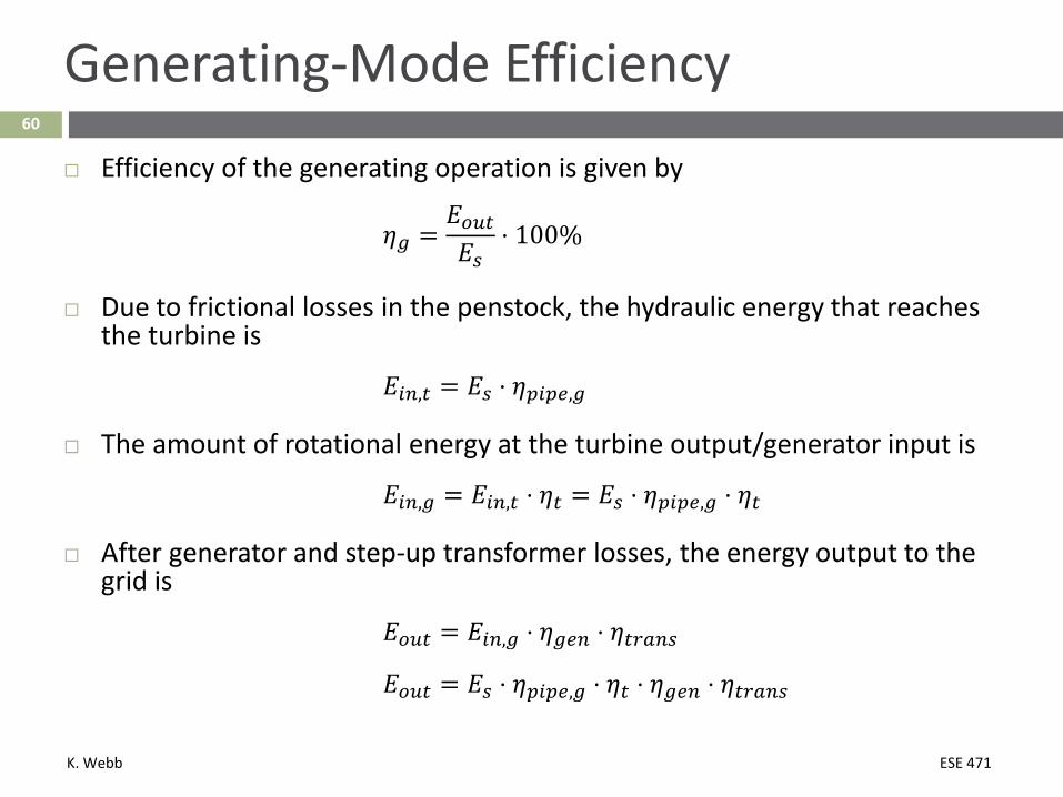
Generating-Mode Efficiency
Efficiency of the generating operation is given by
𝜂𝜂𝑔𝑔 =𝐸𝐸𝑜𝑜𝑢𝑢𝑡𝑡𝐸𝐸𝑠𝑠
⋅ 100%
Due to frictional losses in the penstock, the hydraulic energy that reaches the turbine is
𝐸𝐸𝑖𝑖𝑖𝑖,𝑡𝑡 = 𝐸𝐸𝑠𝑠 ⋅ 𝜂𝜂𝑝𝑝𝑖𝑖𝑝𝑝𝑝𝑝,𝑔𝑔
The amount of rotational energy at the turbine output/generator input is
𝐸𝐸𝑖𝑖𝑖𝑖,𝑔𝑔 = 𝐸𝐸𝑖𝑖𝑖𝑖,𝑡𝑡 ⋅ 𝜂𝜂𝑡𝑡 = 𝐸𝐸𝑠𝑠 ⋅ 𝜂𝜂𝑝𝑝𝑖𝑖𝑝𝑝𝑝𝑝,𝑔𝑔 ⋅ 𝜂𝜂𝑡𝑡
After generator and step-up transformer losses, the energy output to the grid is
𝐸𝐸𝑜𝑜𝑢𝑢𝑡𝑡 = 𝐸𝐸𝑖𝑖𝑖𝑖,𝑔𝑔 ⋅ 𝜂𝜂𝑔𝑔𝑝𝑝𝑖𝑖 ⋅ 𝜂𝜂𝑡𝑡𝑟𝑟𝑡𝑡𝑖𝑖𝑠𝑠
𝐸𝐸𝑜𝑜𝑢𝑢𝑡𝑡 = 𝐸𝐸𝑠𝑠 ⋅ 𝜂𝜂𝑝𝑝𝑖𝑖𝑝𝑝𝑝𝑝,𝑔𝑔 ⋅ 𝜂𝜂𝑡𝑡 ⋅ 𝜂𝜂𝑔𝑔𝑝𝑝𝑖𝑖 ⋅ 𝜂𝜂𝑡𝑡𝑟𝑟𝑡𝑡𝑖𝑖𝑠𝑠
K. Webb ESE 471
61
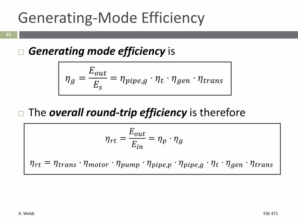
Generating-Mode Efficiency
Generating mode efficiency is
𝜂𝜂𝑔𝑔 =𝐸𝐸𝑜𝑜𝑢𝑢𝑡𝑡𝐸𝐸𝑠𝑠
= 𝜂𝜂𝑝𝑝𝑖𝑖𝑝𝑝𝑝𝑝,𝑔𝑔 ⋅ 𝜂𝜂𝑡𝑡 ⋅ 𝜂𝜂𝑔𝑔𝑝𝑝𝑖𝑖 ⋅ 𝜂𝜂𝑡𝑡𝑟𝑟𝑡𝑡𝑖𝑖𝑠𝑠
The overall round-trip efficiency is therefore
𝜂𝜂𝑟𝑟𝑡𝑡 =𝐸𝐸𝑜𝑜𝑢𝑢𝑡𝑡𝐸𝐸𝑖𝑖𝑖𝑖
= 𝜂𝜂𝑝𝑝 ⋅ 𝜂𝜂𝑔𝑔
𝜂𝜂𝑟𝑟𝑡𝑡 = 𝜂𝜂𝑡𝑡𝑟𝑟𝑡𝑡𝑖𝑖𝑠𝑠 ⋅ 𝜂𝜂𝑚𝑚𝑜𝑜𝑡𝑡𝑜𝑜𝑟𝑟 ⋅ 𝜂𝜂𝑝𝑝𝑢𝑢𝑚𝑚𝑝𝑝 ⋅ 𝜂𝜂𝑝𝑝𝑖𝑖𝑝𝑝𝑝𝑝,𝑝𝑝 ⋅ 𝜂𝜂𝑝𝑝𝑖𝑖𝑝𝑝𝑝𝑝,𝑔𝑔 ⋅ 𝜂𝜂𝑡𝑡 ⋅ 𝜂𝜂𝑔𝑔𝑝𝑝𝑖𝑖 ⋅ 𝜂𝜂𝑡𝑡𝑟𝑟𝑡𝑡𝑖𝑖𝑠𝑠
K. Webb ESE 471
62
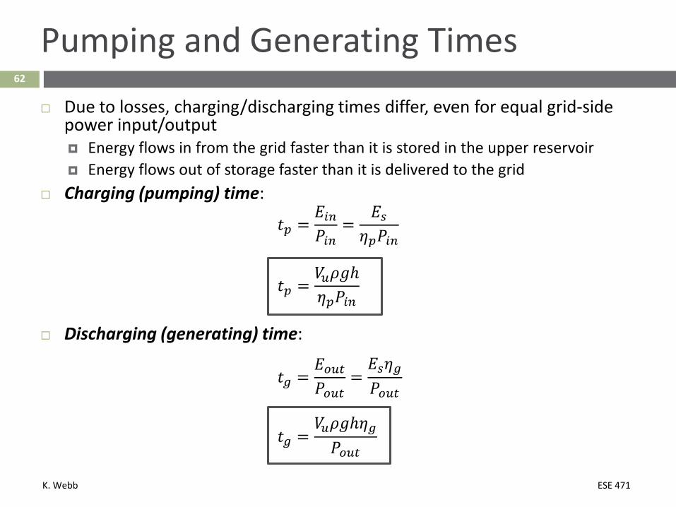
Pumping and Generating Times
Due to losses, charging/discharging times differ, even for equal grid-side power input/output Energy flows in from the grid faster than it is stored in the upper reservoir Energy flows out of storage faster than it is delivered to the grid
Charging (pumping) time:
𝑡𝑡𝑝𝑝 =𝐸𝐸𝑖𝑖𝑖𝑖𝑃𝑃𝑖𝑖𝑖𝑖
=𝐸𝐸𝑠𝑠
𝜂𝜂𝑝𝑝𝑃𝑃𝑖𝑖𝑖𝑖
𝑡𝑡𝑝𝑝 =𝑉𝑉𝑢𝑢𝜌𝜌𝑚𝑚ℎ𝜂𝜂𝑝𝑝𝑃𝑃𝑖𝑖𝑖𝑖
Discharging (generating) time:
𝑡𝑡𝑔𝑔 =𝐸𝐸𝑜𝑜𝑢𝑢𝑡𝑡𝑃𝑃𝑜𝑜𝑢𝑢𝑡𝑡
=𝐸𝐸𝑠𝑠𝜂𝜂𝑔𝑔𝑃𝑃𝑜𝑜𝑢𝑢𝑡𝑡
𝑡𝑡𝑔𝑔 =𝑉𝑉𝑢𝑢𝜌𝜌𝑚𝑚ℎ𝜂𝜂𝑔𝑔𝑃𝑃𝑜𝑜𝑢𝑢𝑡𝑡
K. Webb ESE 471
63
Pumping and Generating Times
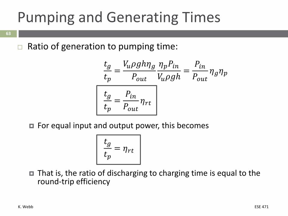
Ratio of generation to pumping time:
𝑡𝑡𝑔𝑔𝑡𝑡𝑝𝑝
=𝑉𝑉𝑢𝑢𝜌𝜌𝑚𝑚ℎ𝜂𝜂𝑔𝑔𝑃𝑃𝑜𝑜𝑢𝑢𝑡𝑡
𝜂𝜂𝑝𝑝𝑃𝑃𝑖𝑖𝑖𝑖𝑉𝑉𝑢𝑢𝜌𝜌𝑚𝑚ℎ
=𝑃𝑃𝑖𝑖𝑖𝑖𝑃𝑃𝑜𝑜𝑢𝑢𝑡𝑡
𝜂𝜂𝑔𝑔𝜂𝜂𝑝𝑝
𝑡𝑡𝑔𝑔𝑡𝑡𝑝𝑝
=𝑃𝑃𝑖𝑖𝑖𝑖𝑃𝑃𝑜𝑜𝑢𝑢𝑡𝑡
𝜂𝜂𝑟𝑟𝑡𝑡
For equal input and output power, this becomes
𝑡𝑡𝑔𝑔𝑡𝑡𝑝𝑝
= 𝜂𝜂𝑟𝑟𝑡𝑡
That is, the ratio of discharging to charging time is equal to the round-trip efficiency

K. Webb ESE 471
Example PHES Projects64

K. Webb ESE 471
65
Raccoon Mountain
Marion County, TN Open-loop PHES
Mountaintop upper reservoir 46x106 m3 of water
Tennessee River is lower reservoir
Generating time: 22 hours Pumping time: 28 hours Usage: peaking generation, grid
balancing
Power: 1652 MW 4 x 413 MW
pump/turbine units Energy: 36.3 GWh Pump/turbines:
single-stage reversible Francis
RT efficiency: 79% Commissioned: 1978 Penstock diameter:
10.7 m Head: 273 – 317 m
K. Webb ESE 471
66
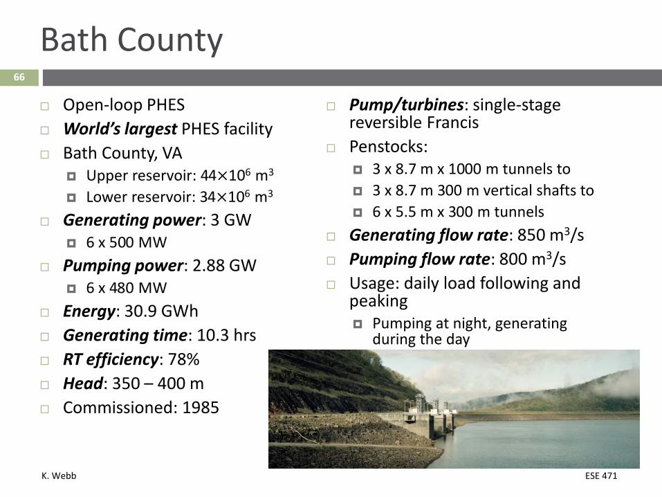
Bath County
Open-loop PHES World’s largest PHES facility Bath County, VA
Upper reservoir: 44×106 m3
Lower reservoir: 34×106 m3
Generating power: 3 GW 6 x 500 MW
Pumping power: 2.88 GW 6 x 480 MW
Energy: 30.9 GWh Generating time: 10.3 hrs RT efficiency: 78% Head: 350 – 400 m Commissioned: 1985
Pump/turbines: single-stage reversible Francis
Penstocks: 3 x 8.7 m x 1000 m tunnels to 3 x 8.7 m 300 m vertical shafts to 6 x 5.5 m x 300 m tunnels
Generating flow rate: 850 m3/s Pumping flow rate: 800 m3/s Usage: daily load following and
peaking Pumping at night, generating
during the day
K. Webb ESE 471
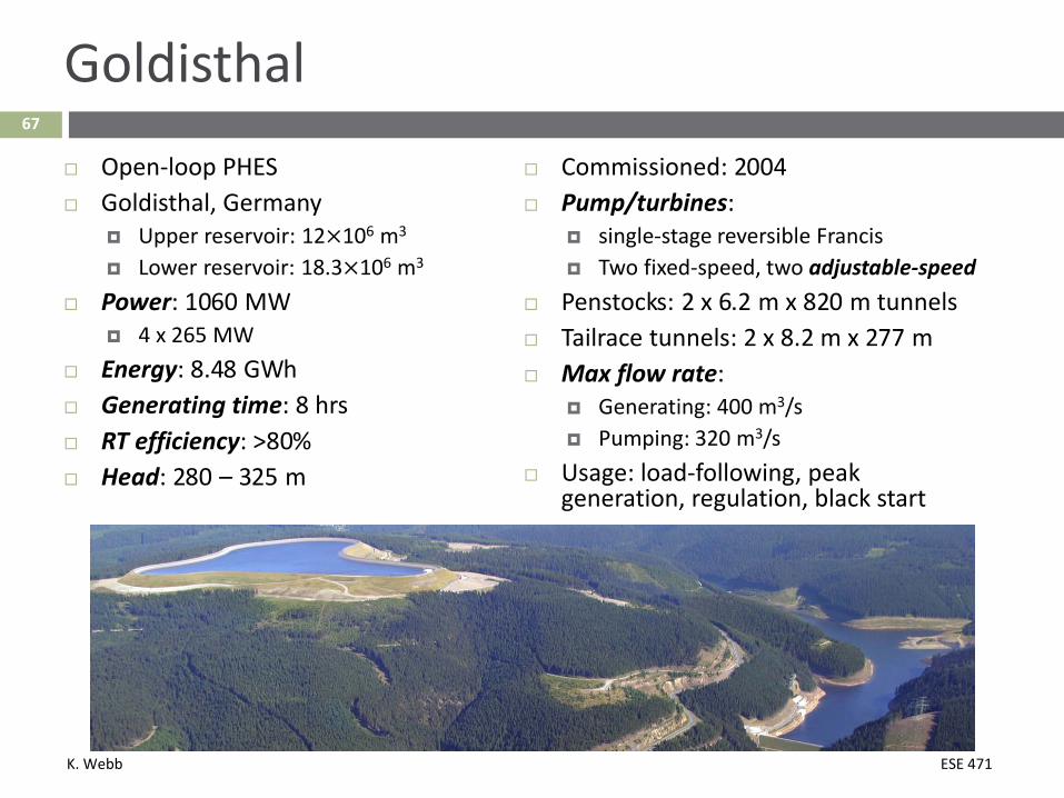
67
Goldisthal Open-loop PHES Goldisthal, Germany
Upper reservoir: 12×106 m3
Lower reservoir: 18.3×10⁶ m3
Power: 1060 MW 4 x 265 MW
Energy: 8.48 GWh Generating time: 8 hrs RT efficiency: >80% Head: 280 – 325 m
Commissioned: 2004 Pump/turbines:
single-stage reversible Francis Two fixed-speed, two adjustable-speed
Penstocks: 2 x 6.2 m x 820 m tunnels Tailrace tunnels: 2 x 8.2 m x 277 m Max flow rate:
Generating: 400 m3/s Pumping: 320 m3/s
Usage: load-following, peak generation, regulation, black start

K. Webb ESE 471
Rail Energy Storage68
K. Webb ESE 471
69
Disadvantages of PHES
Disadvantages of PHES Environmental issues Water usage River/habitat disruption
Head variation Pressure drops as upper reservoir drains Efficiency may vary throughout charge/discharge cycle Particularly an issue for lower-head plants with steep, narrow upper
reservoirs Siting options are limited Available water Favorable topography Large land area
Possible alternative potential energy storage: Rail energy storage
K. Webb ESE 471
70
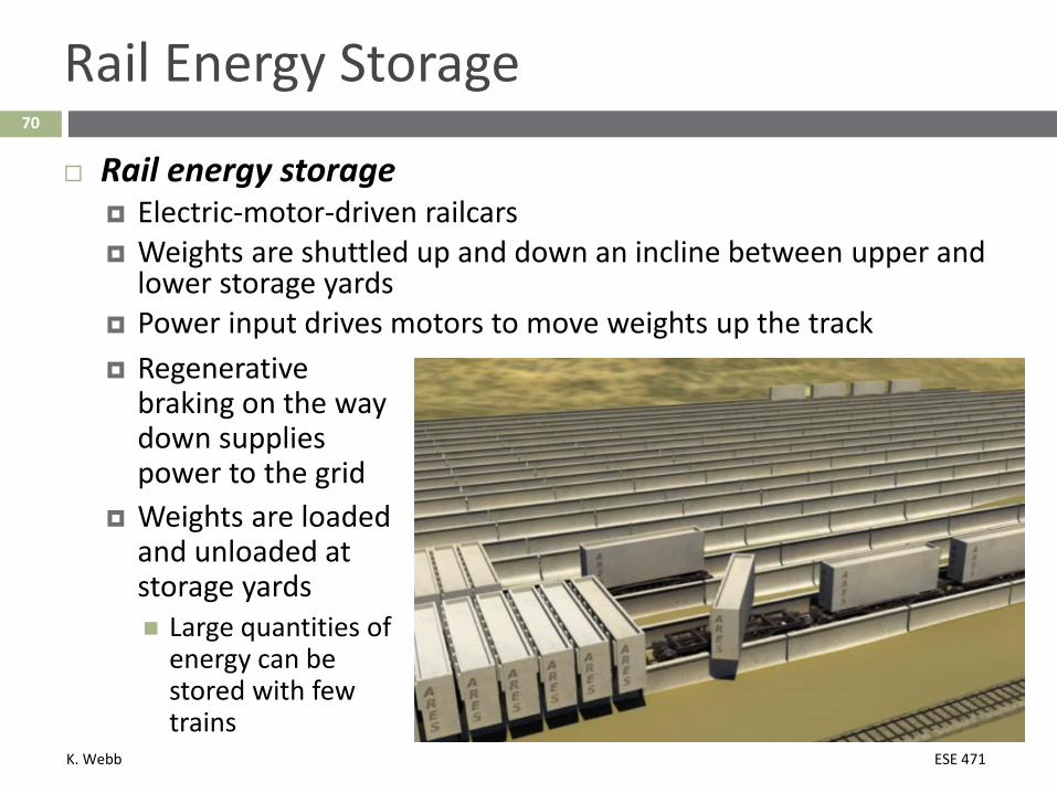
Rail Energy Storage
Rail energy storage Electric-motor-driven railcars Weights are shuttled up and down an incline between upper and
lower storage yards Power input drives motors to move weights up the track Regenerative
braking on the way down supplies power to the grid
Weights are loaded and unloaded at storage yards Large quantities of
energy can be stored with few trains

K. Webb ESE 471
71
Advantages of Rail Energy Storage
More siting options than for PHES Open space Elevation change No need for water or
topography conducive to reservoirs
Lower capital cost than PHES Easily scalable Efficient
RT efficiency: 78% - 86% Constant efficiency,
independent of SoC No standby losses
No evaporation/leakage
K. Webb ESE 471
72
Rail Energy Storage
ARES North America Scale prototype project constructed in Tehachapi, CA 50 MW frequency regulation project planned for southern
Nevada
ARES Nevada Location: BLM land, Pahrump, NV Power: 50 MW Energy: 12.5 MWh Generating time at rated power: 15 min Track length: 9 km (5.5 mi) Elevation difference: 610 m (2000 ft) Total mass: 8.7 x 10⁶ kg (9600 US tons) Footprint: 46 acres Status: licensing, permitting, and environmental review phase

K. Webb ESE 471
73
Rail Energy Storage
Three categories of rail energy storage plants proposed by ARES: Small 20 – 50 MW Ancillary services only
Intermediate 50 – 200 MW Ancillary services,
integration of renewables
Grid-scale 200 MW – 3 GW 4 – 16 hours of storage at full power
K. Webb ESE 471
74
Rail Energy Storage
Conceptual grid-scale storage facility (as proposed by ARES) Power: 670 MW Energy: 5360 MWh Discharge time: 8 hr Elevation differential: 915 m (3000 ft) Five tracks Length: 13 km (8 mi) Grade: 7.5%
140 4-car shuttle trains 11,400 concrete weights Mass of each: 212 x 103 kg (234 US tons) Total mass: 2.42 x 10⁹ kg (2.67 x 10⁶ tons)
Capital costs: $1350/kW $168/kWh