Embed Size (px)
Citation preview
3.1
Force Control Industries, Inc.
3II
Posistop X Class BrakeSection 3
Oil Shear Brakes
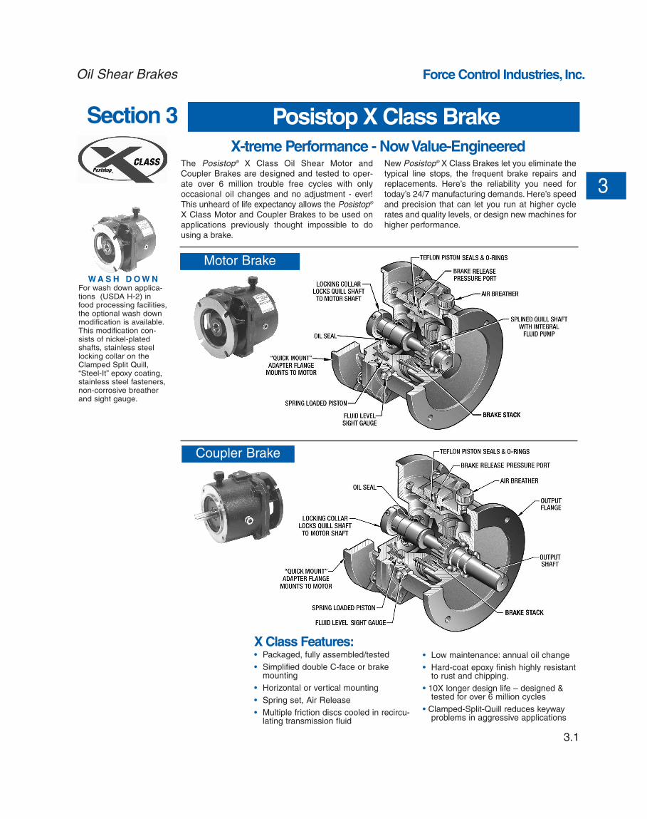
X-treme Performance - Now Value-EngineeredThe Posistop® X Class Oil Shear Motor and
Coupler Brakes are designed and tested to oper-
ate over 6 million trouble free cycles with only
occasional oil changes and no adjustment - ever!
This unheard of life expectancy allows the Posistop®
X Class Motor and Coupler Brakes to be used on
applications previously thought impossible to do
using a brake.
New Posistop® X Class Brakes let you eliminate the
typical line stops, the frequent brake repairs and
replacements. Here’s the reliability you need for
today’s 24/7 manufacturing demands. Here’s speed
and precision that can let you run at higher cycle
rates and quality levels, or design new machines for
higher performance.
X Class Features:• Packaged, fully assembled/tested
• Simplified double C-face or brakemounting
• Horizontal or vertical mounting
• Spring set, Air Release
• Multiple friction discs cooled in recircu-lating transmission fluid
• Low maintenance: annual oil change
• Hard-coat epoxy finish highly resistantto rust and chipping.
• 10X longer design life – designed &tested for over 6 million cycles
• Clamped-Split-Quill reduces keywayproblems in aggressive applications
Motor Brake
Coupler Brake
W A S H D O W NFor wash down applica-tions (USDA H-2) infood processing facilities,the optional wash downmodification is available.This modification con-sists of nickel-platedshafts, stainless steellocking collar on theClamped Split Quill,“Steel-It” epoxy coating,stainless steel fasteners,non-corrosive breatherand sight gauge.
3.2
Force Control Industries, Inc. Oil Shear Brakes
3
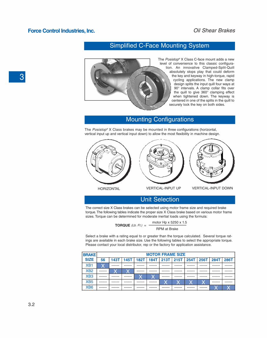
The Posistop® X Class C-face mount adds a newlevel of convenience to this classic configura-
tion. An innovative Clamped-Split-Quillabsolutely stops play that could deform
the key and keyway in high-torque, rapidcycling applications. The new clampdesign splits the input quill four ways at90° intervals. A clamp collar fits overthe quill to give 360° clamping effectwhen tightened down. The keyway is
centered in one of the splits in the quill tosecurely lock the key on both sides.
Simplified C-Face Mounting System
Mounting Configurations
Unit Selection
HORIZONTAL VERTICAL-INPUT UP VERTICAL-INPUT DOWN
The Posistop® X Class brakes may be mounted in three configurations (horizontal,
vertical input up and vertical input down) to allow the most flexibility in machine design.
BRAKE
SIZE
MOTOR FRAME SIZE
56 143T 145T 182T 184T 213T 215T 254T 256T 284T 286T
XB1 X ------ ------ ------ ------ ------ ------ ------ ------ ------ ------
XB2 ------ X X ------ ------ ------ ------ ------ ------ ------ ------
XB3 ------ ------ ------ X X ------ ------ ------ ------ ------ ------
XB5 ------ ------ ------ ------ ------ X X X X ------ ------
XB6 ------ ------ ------ ------ ------ ------ ------ ------ ------ X X
The correct size X Class brakes can be selected using motor frame size and required brake
torque. The following tables indicate the proper size X Class brake based on various motor frame
sizes. Torque can be determined for moderate inertial loads using the formula:
Select a brake with a rating equal to or greater than the torque calculated. Several torque rat-
ings are available in each brake size. Use the following tables to select the appropriate torque.
Please contact your local distributor, rep or the factory for application assistance.
TORQUE (Lb. Ft.) =motor Hp x 5250 x 1.5
RPM at Brake
3.3
Force Control Industries, Inc.Oil Shear Brakes
3II
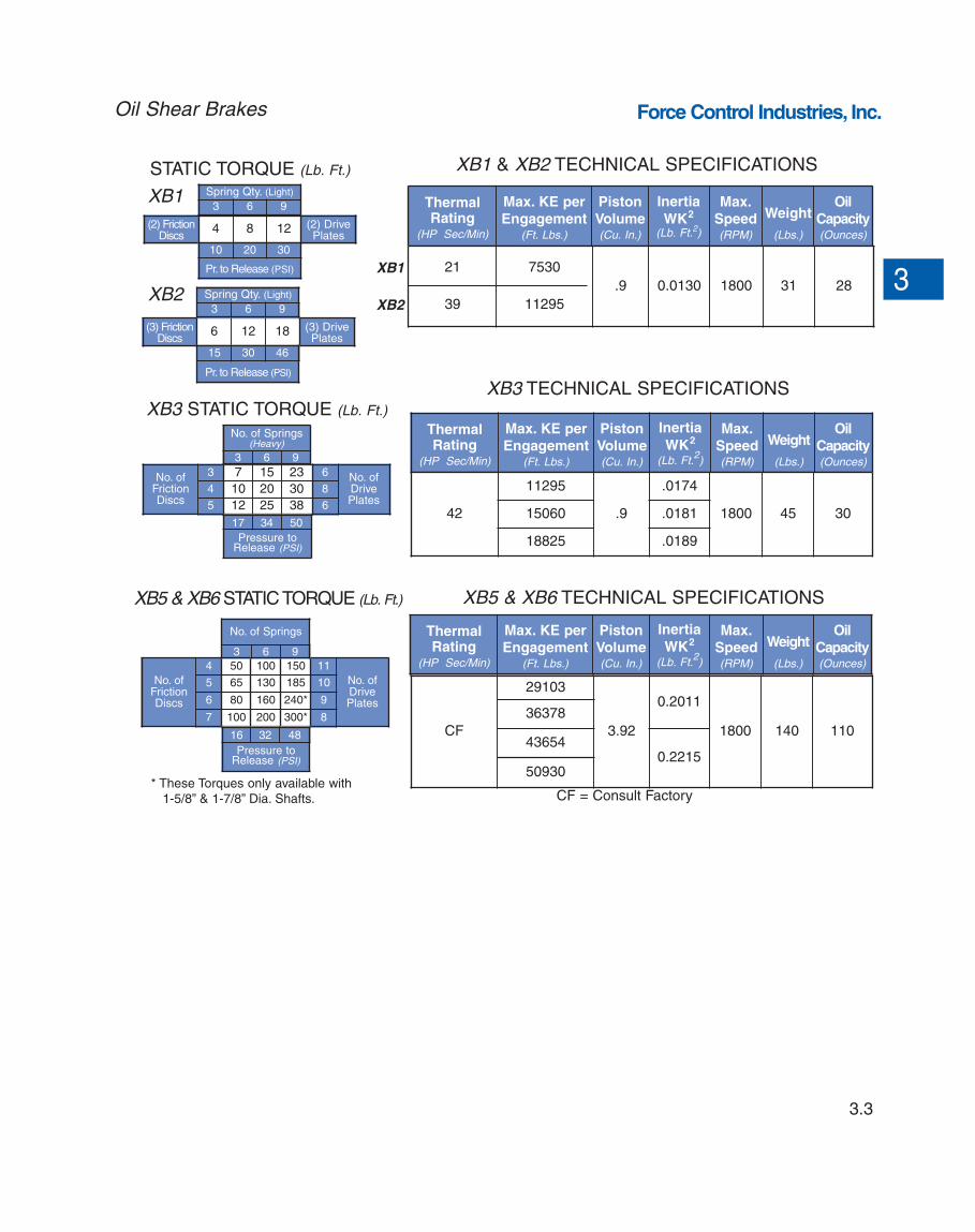
STATIC TORQUE (Lb. Ft.) XB1 & XB2 TECHNICAL SPECIFICATIONS
XB3 TECHNICAL SPECIFICATIONS
ThermalRating
(HP Sec/Min)
Max. KE per
Engagement(Ft. Lbs.)
Piston
Volume(Cu. In.)
Inertia
WK2
(Lb. Ft.2)
Max.
Speed(RPM)
Weight
(Lbs.)
Oil
Capacity(Ounces)
21
39
7530
11295
.9 0.0130 1800 31 28
ThermalRating
(HP Sec/Min)
Max. KE per
Engagement(Ft. Lbs.)
Piston
Volume(Cu. In.)
Inertia
WK2
(Lb. Ft.2)
Max.
Speed(RPM)
Weight
(Lbs.)
Oil
Capacity(Ounces)
42
11295
.9
.0174
1800 45 3015060 .0181
18825 .0189
(2) FrictionDiscs
4 8 12 (2) DrivePlates
Spring Qty. (Light)
3 6 9
10 20 30
Pr. to Release (PSI)
(3) FrictionDiscs
6 12 18 (3) DrivePlates
Spring Qty. (Light)
3 6 9
15 30 46
Pr. to Release (PSI)
XB1
XB2
XB3 STATIC TORQUE (Lb. Ft.)
No. ofFrictionDiscs
3 7 15 23 6 No. ofDrivePlates
4 10 20 30 8
5 12 25 38 6
No. of Springs(Heavy)
3 6 9
17 34 50
Pressure toRelease (PSI)
XB1
XB2
XB5 & XB6 TECHNICAL SPECIFICATIONSXB5 & XB6 STATIC TORQUE (Lb. Ft.)
No. ofFrictionDiscs
4 50 100 150 11
No. ofDrivePlates
5 65 130 185 10
6 80 160 240* 9
7 100 200 300* 8
No. of Springs
3 6 9
16 32 48
Pressure toRelease (PSI)
CF = Consult Factory* These Torques only available with
1-5/8” & 1-7/8” Dia. Shafts.
ThermalRating
(HP Sec/Min)
Max. KE per
Engagement(Ft. Lbs.)
Piston
Volume(Cu. In.)
Inertia
WK2
(Lb. Ft.2)
Max.
Speed(RPM)
Weight
(Lbs.)
Oil
Capacity(Ounces)
CF
29103
3.92
0.2011
1800 140 110
36378
436540.2215
50930
3.4
Force Control Industries, Inc. Oil Shear Brakes
3
BrakeSize
Coupler Brake Overall Dimensions (Inches)
AA AB AG F G P QXB1
3.51 3.77 7.00 3.44 4.50 1/8 NPT 4.94XB2
XB3 4.44 4.44 8.46 4.44 5.08 1/8 NPT 4.94
XB5 5.00 5.0011.45 5.50 6.64 1/4 NPT -----
XB6 5.50 5.50
Brake
Size
Coupler Brake Input Dimensions (Inches)
AL BE E FAH FAJ FAK FU FBF
XB1.63 .50 .28 2.38 5.88 4.502
4.5005/8
7/16XB2 7/8
XB3 .57 .73 .19 2.94 7.25 8.502 1-1/8 9/16
XB5.71 .69
----- 3.88 7.25 ----- *9/16
XB6 ----- 4.88 9.00 ----- *
Brake
Size
Coupler Brake Output Dimensions (Inches)
a AH AJ AK BB BF U XD
XB13/16 x 3/32
2.065.875 4.50 .16 3/8-16
5/8 1.50
XB2 2.12 7/8 1.73
XB3 1/4 x 1/8 2.63 7.250 8.50 .25 1/2-13 1-1/8 2.00
XB51/4 x 1/8
5/16 x 5/323/8 x 3/16
2.753.123.75
7.250 8.50.25 1/2-13
1-1/81-3/81-5/8
2.653.003.63
XB63/8 x 3/161/2 x 1/4
4.624.37
9.000 10.501-5/81-7/8
3.693.62
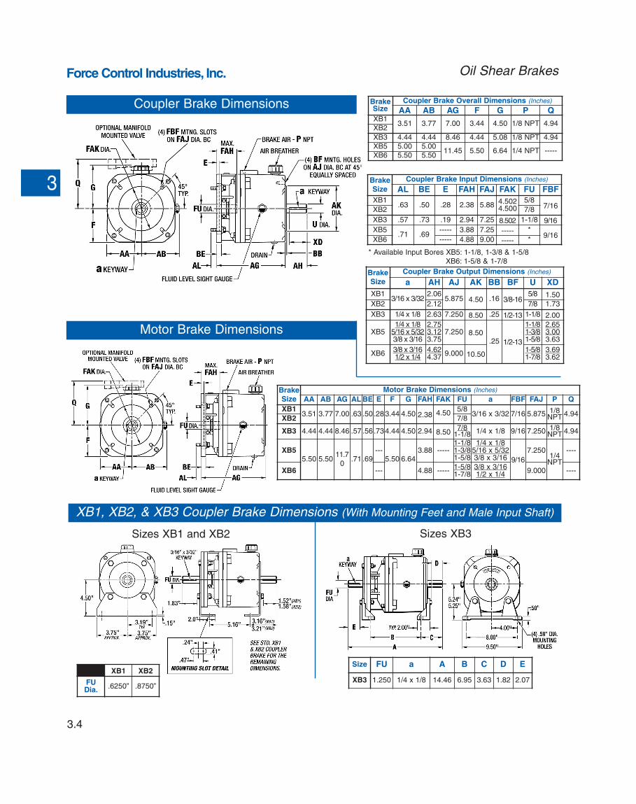
Coupler Brake Dimensions
Motor Brake Dimensions
* Available Input Bores XB5: 1-1/8, 1-3/8 & 1-5/8
XB6: 1-5/8 & 1-7/8
Brake
Size
Motor Brake Dimensions (Inches)
AA AB AG AL BE E F G FAH FAK FU a FBF FAJ P Q
XB13.51 3.77 7.00 .63 .50.283.44 4.50 2.38 4.50
5/83/16 x 3/32 7/16 5.875 1/8
NPT 4.94XB2 7/8
XB3 4.44 4.44 8.46 .57 .56.734.44 4.50 2.94 8.507/8
1-1/8 1/4 x 1/8 9/16 7.250 1/8NPT 4.94
XB55.50 5.50
11.7
0.71 .69
---5.50 6.64
3.88 -----1-1/81-3/81-5/8
1/4 x 1/85/16 x 5/323/8 x 3/16 9/16
7.2501/4
NPT
----
XB6 --- 4.88 -----1-5/81-7/8
3/8 x 3/161/2 x 1/4
9.000 ----
XB1, XB2, & XB3 Coupler Brake Dimensions (With Mounting Feet and Male Input Shaft)
Sizes XB1 and XB2 Sizes XB3
Size FU a A B C D E
XB3 1.250 1/4 x 1/8 14.46 6.95 3.63 1.82 2.07
XB1 XB2
FUDia.
.6250” .8750”
Spring
Set
Brake (3)
3.5
Force Control Industries, Inc.
Q
4.94
4.94
----
----
Oil Shear Brakes
3
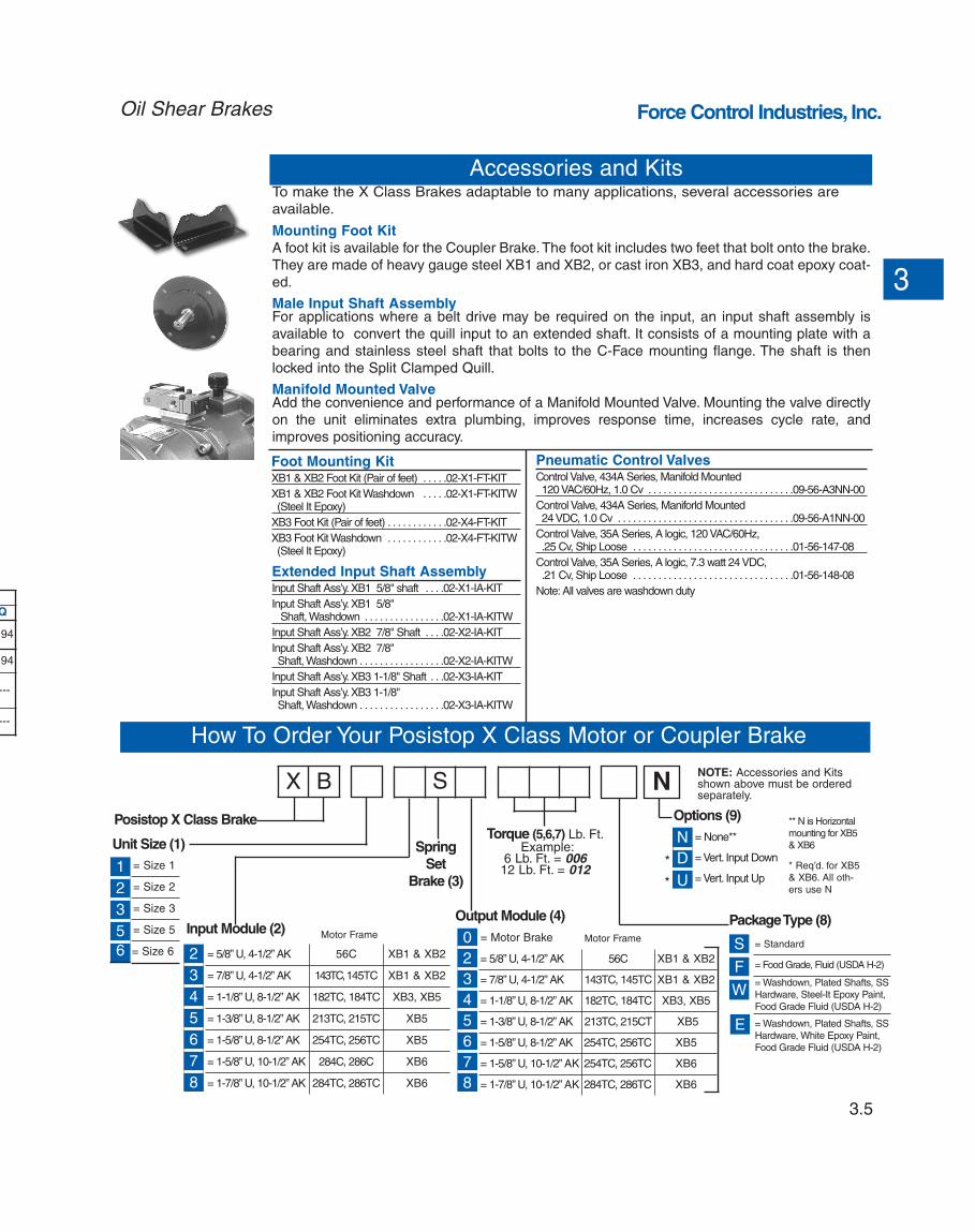
Accessories and Kits
How To Order Your Posistop X Class Motor or Coupler Brake
N
Posistop X Class Brake
Unit Size (1)
= Size 1
= Size 2
= Size 3
= Size 5
= Size 6
Package Type (8)
Options (9)
N
D
U
= None**
= Vert. Input Down
= Vert. Input Up
Input Module (2)
2
3
4
5
6
7
8
= 5/8” U, 4-1/2” AK 56C XB1 & XB2
= 7/8” U, 4-1/2” AK 143TC, 145TC XB1 & XB2
= 1-1/8” U, 8-1/2” AK 182TC, 184TC XB3, XB5
= 1-3/8” U, 8-1/2” AK 213TC, 215TC XB5
= 1-5/8” U, 8-1/2” AK 254TC, 256TC XB5
= 1-5/8” U, 10-1/2” AK 284C, 286C XB6
= 1-7/8” U, 10-1/2” AK 284TC, 286TC XB6
= 5/8” U, 4-1/2” AK 56C XB1 & XB2
= 7/8” U, 4-1/2” AK 143TC, 145TC XB1 & XB2
= 1-1/8” U, 8-1/2” AK 182TC, 184TC XB3, XB5
= 1-3/8” U, 8-1/2” AK 213TC, 215CT XB5
= 1-5/8” U, 8-1/2” AK 254TC, 256TC XB5
= 1-5/8” U, 10-1/2” AK 254TC, 256TC XB6
= 1-7/8” U, 10-1/2” AK 284TC, 286TC XB6
Output Module (4)
0
2
3
4
5
6
7
8
NOTE: Accessories and Kitsshown above must be orderedseparately.
Motor Frame Motor Frame
1
2
3
5
6= Motor Brake
*
*
X B S
Torque (5,6,7) Lb. Ft.Example:
6 Lb. Ft. = 00612 Lb. Ft. = 012 * Req’d. for XB5
& XB6. All oth-
ers use N
= Standard
= Food Grade, Fluid (USDA H-2)
= Washdown, Plated Shafts, SS
Hardware, Steel-It Epoxy Paint,
Food Grade Fluid (USDA H-2)
= Washdown, Plated Shafts, SS
Hardware, White Epoxy Paint,
Food Grade Fluid (USDA H-2)
S
F
W
E
** N is Horizontal
mounting for XB5
& XB6
To make the X Class Brakes adaptable to many applications, several accessories are
available.
Mounting Foot Kit
A foot kit is available for the Coupler Brake.The foot kit includes two feet that bolt onto the brake.
They are made of heavy gauge steel XB1 and XB2, or cast iron XB3, and hard coat epoxy coat-
ed.
Male Input Shaft AssemblyFor applications where a belt drive may be required on the input, an input shaft assembly is
available to convert the quill input to an extended shaft. It consists of a mounting plate with a
bearing and stainless steel shaft that bolts to the C-Face mounting flange. The shaft is then
locked into the Split Clamped Quill.
Manifold Mounted ValveAdd the convenience and performance of a Manifold Mounted Valve. Mounting the valve directly
on the unit eliminates extra plumbing, improves response time, increases cycle rate, and
improves positioning accuracy.
Foot Mounting Kit XB1 & XB2 Foot Kit (Pair of feet) . . . . .02-X1-FT-KIT
XB1 & XB2 Foot Kit Washdown . . . . .02-X1-FT-KITW(Steel It Epoxy)
XB3 Foot Kit (Pair of feet) . . . . . . . . . . . .02-X4-FT-KIT
XB3 Foot Kit Washdown . . . . . . . . . . . .02-X4-FT-KITW(Steel It Epoxy)
Extended Input Shaft AssemblyInput Shaft Ass’y.XB1 5/8" shaft . . . .02-X1-IA-KIT
Input Shaft Ass’y.XB1 5/8"Shaft, Washdown . . . . . . . . . . . . . . . .02-X1-IA-KITW
Input Shaft Ass’y.XB2 7/8" Shaft . . . .02-X2-IA-KIT
Input Shaft Ass’y.XB2 7/8" Shaft, Washdown . . . . . . . . . . . . . . . . .02-X2-IA-KITW
Input Shaft Ass’y.XB3 1-1/8" Shaft . . .02-X3-IA-KIT
Input Shaft Ass’y.XB3 1-1/8" Shaft, Washdown . . . . . . . . . . . . . . . . .02-X3-IA-KITW
Pneumatic Control ValvesControl Valve, 434A Series, Manifold Mounted120 VAC/60Hz, 1.0 Cv . . . . . . . . . . . . . . . . . . . . . . . . . . . . .09-56-A3NN-00
Control Valve, 434A Series, Maniforld Mounted24 VDC, 1.0 Cv . . . . . . . . . . . . . . . . . . . . . . . . . . . . . . . . . . .09-56-A1NN-00
Control Valve, 35A Series, A logic, 120 VAC/60Hz, .25 Cv, Ship Loose . . . . . . . . . . . . . . . . . . . . . . . . . . . . . . . .01-56-147-08
Control Valve, 35A Series, A logic, 7.3 watt 24 VDC, .21 Cv, Ship Loose . . . . . . . . . . . . . . . . . . . . . . . . . . . . . . . .01-56-148-08
Note: All valves are washdown duty


![AC/DC Geared Motor and Gearhead - raveo.czkatalog]_DKM_A... · DKM Products Overview Induction Motor 2 Pole Motor Reversible Motor E.M. Brake Motor Clutch & Brake Motor Torque Motor](https://img.pdfslide.us/doc/110x75/5ca5afa988c9930a6e8c9362/acdc-geared-motor-and-gearhead-raveocz-katalogdkma-dkm-products-overview.jpg)