Embed Size (px)
Citation preview
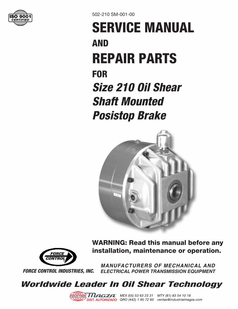
SERVICE MANUALAND
REPAIR PARTSFORSize 210 Oil ShearShaft MountedPosistop Brake
WARNING: Read this manual before any installation, maintenance or operation.
MANUFACTURERS OF MECHANICAL ANDELECTRICAL POWER TRANSMISSION EQUIPMENT
502-210 SM-001-00
FORCE CONTROL INDUSTRIES, INC.
Worldwide Leader In Oil Shear Technology®
DIST. AUTORIZADOMEX (55) 53 63 23 31QRO (442) 1 95 72 60
MTY (81) 83 54 10 [email protected]
Limited Warranty
Force Control Industries, Inc. (“Force Control”) warrants its products to be free from defects in material and workmanship under normal and proper use for a period of one year from the date of shipment. Any products purchased from Force Control that upon inspection at Force Controlʼs factory prove to be defective as a result of normal use during the one year period will be repaired or replaced (at Force Controlsʼ option) without any charge for parts or labor. This limited warranty shall be void in regard to (1) any product or part thereof which has been altered or repaired by a buyer without Force Controlʼs previous written consent or (2) any product or part thereof that has been subjected to unusual electrical, physical or mechanical stress, or upon which the original identification marks have been removed or altered. Transportation charges for shipping any product or part thereof that the buyer claims is covered by this limited warranty shall be paid by the buyer. If Force Control determines that any product or part thereof should be repaired or replaced under the terms of this limited warranty it will pay for shipping the repaired or replaced product or part thereof back to the buyer. EXCEPT FOR THE EXPRESS WARRANTY SET OUT ABOVE, FORCE CONTROL DOES NOT GRANT ANY WARRANTIES EITHER EXPRESSED OR IMPLIED, INCLUDING IMPLIED WARRANTIES OF MERCHANTABILITY OR FITNESS FOR USE. The warranty obligation set forth above is in lieu of all obligations or liabilities of Force Control for any damages. Force Control specifically shall not be liable for any costs incurred by the buyer in disconnecting or re-installing any product or part thereof repaired or replace under the limited warranty set out above. FORCE CONTROL EXPRESSLY EXCLUDES ALL LIABILITY FOR ANY INDIRECT OR CONSEQUENTIAL DAMAGES THE BUYER MAY SUSTAIN IN CONNECTION WITH THE DELIVERY, USE, OR PERFORMANCE OF FORCE CONTROL PRODUCTS. Under no circumstances shall any liability for which Force Control is held responsible exceed the selling price to the buyer of the Force Control products that are proven to be defective. This limited warranty may be modified only in writing signed by a duly authorized officer of the company. This limited warranty applies exclusively to Force Control products; warranties for motors and gear reducers and other component parts may be provided by their respective manufactures. Any legal action for breach of any Force Control warranty must be commenced within one year of the date on which the breach is or should have been discovered.
A Return Goods Authorization (RGA) number must be obtained from the factory and clearly marked on the outside of the package before any equipment will be accepted for warranty work. Force Control will pay the shipping costs of returning the owner parts that are covered by warranty.
Force Control believes that the information in this document is accurate. The document has been carefully reviewed for technical accuracy. In the event that technical or typographical errors exist, Force Control reserves the right to make changes to subsequent editions of this document without prior notice to holders of this edition. The reader should consult Force Control if errors are suspected. In no event shall Force Control be liable for any damages arising out of or related to this document or the information contained in it.
®
DIST. AUTORIZADOMEX (55) 53 63 23 31QRO (442) 1 95 72 60
MTY (81) 83 54 10 [email protected]
Section 1 - Description and Operation 1-2 The Oil Shear Principle ................................................................................ 1 1-2 Description .................................................................................................. 1 1-3 Features....................................................................................................... 1 1-4 Operation..................................................................................................... 1
Section 2 - Specifications 2-1 Dimensions.................................................................................................. 3 2-2 Brake Stack Configurations......................................................................... 3 2-3 Operating Specifications ............................................................................. 3
Section 3 - Installation 3-1 Installing Brake to Your shaft....................................................................... 4 3-2 Pneumatic Hook-Up.................................................................................... 5
Section 4 - Lubrication 4-1 Checking the Oil Level................................................................................. 6 4-2 Changing the Oil .......................................................................................... 6 4-3 Type of Oil.................................................................................................... 6 Section 5 - Operational Checks 4-1 Checking for Air Leaks or Internal Damage................................................. 7 4-2 Checking Brake Stack for Wear .................................................................. 7
Section 6 - Troubleshooting Troubleshooting Chart........................................................................................ 8
Section 7 - Disassembly 7-1 Removing the Brake for Repair ................................................................... 9 7-2 Brake Disassembly ...................................................................................... 9
Section 8 - Cleaning, Inspection and Repair 8-1 General Information ..................................................................................... 11 8-2 Cleaning and Inspection.............................................................................. 11 8-3 Repair and Replacement ............................................................................. 11
Section 9 - Reassembly 9-1 General Reassembly Instructions................................................................ 12 9-2 Hub Reassembly ......................................................................................... 12 9-3 Installing Oil Seals ....................................................................................... 13 9-4 Installing New Piston Seals ......................................................................... 13 9-5 Brake Reassembly....................................................................................... 14 9-6 Wear Sleeve Assembly Tool Dimensions..................................................... 15
Section 10 - Ordering Repair Parts 10-1 Ordering Repair Parts................................................................................ 15 10-2 Factory Rebuild Service ............................................................................ 15 Repair Parts List - Figure 10.1 ........................................................................... 16 Figure 10.1 - Size 210 Shaft Mounted Posistop Brake...................................... 17
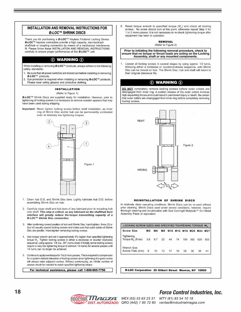
Installation and Removal Instructions for B-Loc Shrink Discs......................... 18
Table of Contents
®
DIST. AUTORIZADOMEX (55) 53 63 23 31QRO (442) 1 95 72 60
MTY (81) 83 54 10 [email protected]

Force Control Industries, Inc. 1®
DIST. AUTORIZADOMEX (55) 53 63 23 31QRO (442) 1 95 72 60
MTY (81) 83 54 10 [email protected]
Force Control Industries, Inc. 1
Section 1 - Description & Operation
1-1 THE OIL SHEAR PRINCIPLEConventional brakes and clutches depend on friction be-tween solid surfaces operating in air to transmit torque. Friction can do the job, but produces a great amount of heat and wear, causing an increase in replacement parts, maintenance, and downtime.
In Force Control Oil Shear Drive Systems the friction surfaces operate in cooling and lubricating fluid. The oil molecules tend to cling to each other as well as the friction surfaces. As moving and stationary elements are brought together, a thin but positive film of oil is main-tained between the friction surfaces, controlled by the clamping pressure and carefully designed grooves in the friction material.
Torque is transmitted from one surface to the other through the viscous shear of the oil film. The friction surfaces are protected by this film and therefore sur-face wear is greatly reduced. The positive flow of fluid between the discs also effectively transmits heat away from the friction surfaces.
1-2 DESCRIPTIONThe Size 210 Shaft Mounted Posistop Brake is a multiple surface, spring activated, pneumatic release braking de-vice that effectively dissipates the heat generated from frequent starting and stopping.
This 210 Posistop Brake has a range of 20 Lb. Ft. to 90 Lb. Ft. of braking torque. This in accomplished with 5 different Brake Stack Configurations, which are de-scribed in Section 2.
The brake is mounted and locked to a driven or jack shaft by a Locking Collar that effectively locks the brake hub to the driven shaft. The torque arm in mounted to the back face of the brake.
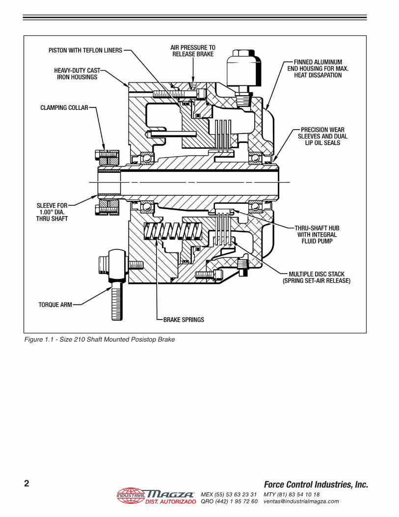
1-3 FEATURES(See Figure 1.1)
• Finned Aluminum Housing for maximum heat dis-sipation.
• Precision Wear Sleeves and Dual-Lip Oil Seals to eliminate any contamination from any harsh envi-ronments.
• Thru-Shaft Hub with Integral Fluid Pump, which maintains a positive an continuous oil film between braking surfaces.
• Multiple Disc Stack - At the heart of your Posis-top Brake is a multiple braking disc stack consisting Drive Plates, keyed to the piston housing and Friction Discs, splined to the hub.
• Heavy-Duty Brake Springs for maximum torque and long braking life.
• Rugged Torque Arm for fast efficient stopping power.
• Locking Collar for a positive locking of the brake hub to the driven or jack shaft.
• Heavy-Duty Cast Iron Housings.
• Piston with Teflon Liners for smooth and consis-tent actuation of the piston.
1-4 OPERATIONThe 210 Shaft Mounted Posistop Brake shown in Fig-ure 1.1 shows the brake in the normally spring-loaded braked position.
Compressed air, controlled by an external valve, enters the piston chamber and moves the piston back to dis-engage the brake stack, allowing the driven or jack shaft to rotate freely.
When the air pressure is released the piston, which is spring loaded, returns to the normal braked position.
®
DIST. AUTORIZADOMEX (55) 53 63 23 31QRO (442) 1 95 72 60
MTY (81) 83 54 10 [email protected]
Force Control Industries, Inc.2 Force Control Industries, Inc. 3
Figure 1.1 - Size 210 Shaft Mounted Posistop Brake
®
DIST. AUTORIZADOMEX (55) 53 63 23 31QRO (442) 1 95 72 60
MTY (81) 83 54 10 [email protected]
Force Control Industries, Inc.2 Force Control Industries, Inc. 3
Section 2 - Specifications
2-1 DIMENSIONS
2-3 OPERATING SPECIFICATIONS
2-2 BRAKE STACK CONFIGURATIONS
BRAKESTACK
CONFIGURATION(See Above)
BRAKE TORQUE (Lb. Ft.) PRESSURETO RELEASE
(PSI)
CYCLICWK2
(Lb. Ft.2)
MAXIMUMKE per
ENGAGEMENT(Ft. Lbs.)
THERMALRATING
(HP Sec./ Min.)
PISTONVOLUME(Cu. In.)
STATIC DYNAMIC
A 20 17 20
.034 6425 25 3
B 30 26 20
C 45 39 28
D 60 52 35
E 90 78 51
20 Lb. Ft.(6) DRIVE PLATES (#12)
(2) FRICTION DISCS (#13)
(2) SPRINGS (#36)
30 Lb. Ft.(4) DRIVE PLATES (#12)
(3) FRICTION DISCS (#13)
(2) SPRINGS (#36)
45 Lb. Ft.(4) DRIVE PLATES (#12)
(3) FRICTION DISCS (#13)
(3) SPRINGS (#36)
60 Lb. Ft.(4) DRIVE PLATES (#12)
(3) FRICTION DISCS (#13)
(4) SPRINGS (#36)
90 Lb. Ft.(4) DRIVE PLATES (#12)
(3) FRICTION DISCS (#13)
(6) SPRINGS (#36)
A B C D E
Maximum Speed - 1800 RPM
PISTON PISTON PISTON PISTON PISTON
®
DIST. AUTORIZADOMEX (55) 53 63 23 31QRO (442) 1 95 72 60
MTY (81) 83 54 10 [email protected]
Force Control Industries, Inc.4
Section 3 - Installation
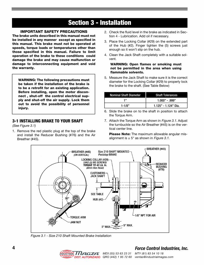
Figure 3.1 - Size 210 Shaft Mounted Brake Installation
IMPORTANT SAFETY PRECAUTIONSThe brake units described in this manual must not be installed in any manner except as specified in this manual. This brake must not be operated at speeds, torque loads or temperatures other than those specified in this manual. Failure to limit operation of the brake to these conditions could damage the brake and may cause malfunction or damage to interconnecting equipment and void the warranty.
WARNING: The following precautions must be taken if the installation of the brake is to be a retrofit for an existing application. Before installing, open the motor discon-nect , shut-off the control electrical sup-ply and shut-off the air supply. Lock them out to avoid the possibility of personnel injury.
3-1 INSTALLING BRAKE TO YOUR SHAFT(See Figure 3.1)
1. Remove the red plastic plug at the top of the brake and install the Reducer Bushing (#76) and the Air Breather (#45).
2. Check the fl uid level in the brake as indicated in Sec-tion 4 - Lubrication. Add oil if necessary.
3. Place the Locking Collar (#29) on the extended part of the Hub (#2). Finger tighten the (5) screws just enough so it won’t slip on the hub.
4. Clean the Jack Shaft completely with a suitable sol-vent.
WARNING: Open flames or smoking must not be permitted in the area when using flammable solvents.
5. Measure the Jack Shaft to make sure it is the correct diameter for the Locking Collar (#29) to properly lock the brake to the shaft. (See Table Below)
Nominal Shaft Diameter Shaft Tolerances
1” 1.000” - .999”
1-1/8” 1.125” - 1.124” Dia.
6. Slide the brake on to the shaft in position to attach the Torque Arm.
7. Attach the Torque Arm as shown in Figure 3.1. Adjust the turnbuckle so the Air Breather (#45) is on the ver-tical center line.
Please Note: The maximum allowable angular mis-alignment is ± 5° as shown in Figure 3.1.
®
DIST. AUTORIZADOMEX (55) 53 63 23 31QRO (442) 1 95 72 60
MTY (81) 83 54 10 [email protected]
Force Control Industries, Inc.4 Force Control Industries, Inc. 5
8. Torque the Locking Collar (#29) to 43 Lb. In. as per manufacturers instructions. (See Installation Sheet in back of this manual.)
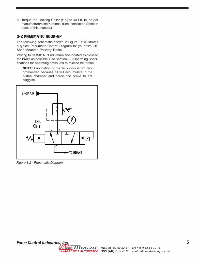
3-2 PNEUMATIC HOOK-UPThe following schematic shown in Figure 3.2 illustrates a typical Pneumatic Control Diagram for your size 210 Shaft Mounted Posistop Brake.
Valving to be 3/8” NPT minimum and located as close to the brake as possible. See Section 2-3 Operating Speci-fications for operating pressures to release the brake.
NOTE: Lubrication of the air supply is not rec-ommended because oil will accumulate in the piston chamber and cause the brake to act sluggish.
Figure 3.2 - Pneumatic Diagram
®
DIST. AUTORIZADOMEX (55) 53 63 23 31QRO (442) 1 95 72 60
MTY (81) 83 54 10 [email protected]
Force Control Industries, Inc.6
Section 4 - Lubrication
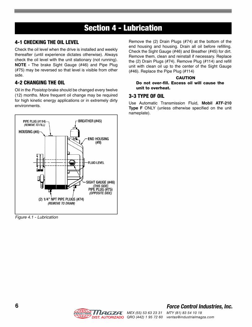
4-1 CHECKING THE OIL LEVELCheck the oil level when the drive is installed and weekly thereafter (until experience dictates otherwise). Always check the oil level with the unit stationary (not running). NOTE - The brake Sight Gauge (#46) and Pipe Plug (#75) may be reversed so that level is visible from other side.
4-2 CHANGING THE OILOil in the Posistop brake should be changed every twelve (12) months. More frequent oil change may be required for high kinetic energy applications or in extremely dirty environments.
Remove the (2) Drain Plugs (#74) at the bottom of the end housing and housing. Drain all oil before refi lling. Check the Sight Gauge (#46) and Breather (#45) for dirt. Remove them, clean and reinstall if necessary. Replace the (2) Drain Plugs (#74). Remove Plug (#114) and refi ll unit with clean oil up to the center of the Sight Gauge (#46). Replace the Pipe Plug (#114)
CAUTIONDo not over-fi ll. Excess oil will cause the unit to overheat.
3-3 TYPE OF OILUse Automatic Transmission Fluid, Mobil ATF-210 Type F ONLY (unless otherwise specifi ed on the unit nameplate).
Figure 4.1 - Lubrication
®
DIST. AUTORIZADOMEX (55) 53 63 23 31QRO (442) 1 95 72 60
MTY (81) 83 54 10 [email protected]
Force Control Industries, Inc.6 Force Control Industries, Inc. 7
Section 5 - Operational ChecksWarning
Make Operational Checks ONLY when the drive motor and motor brake are NOT IN OPERATION. Open motor disconnect and LOCK IT OUT to avoid personal injury.
5-1 CHECKING FOR AIR LEAKS & INTERNAL DAMAGE1. If automatic controls are used, make provisions for
manual operation.2. Remove Air Breather (#45) and Reducer Bushing
(#76) from End Housing (#9). Do not remove while motor is operating.
3. Apply 60 P.S.I. air pressure to the brake and observe the action of the piston through the air breather port. If the piston action is irregular, or if it tends to stick or bind, internal damage may be indicated.
4. Listen and look for air bubbles in the oil, which would indicate piston leakage.
5. If the piston moves slowly and leaks are evident, the piston seals may be damaged.
6. Exhaust the air pressure and observe that the piston returns quickly and smoothly back to normal braking position.
7. Re-install the Reducer Bushing (#76) and Air Breather (#45) in the end housing.
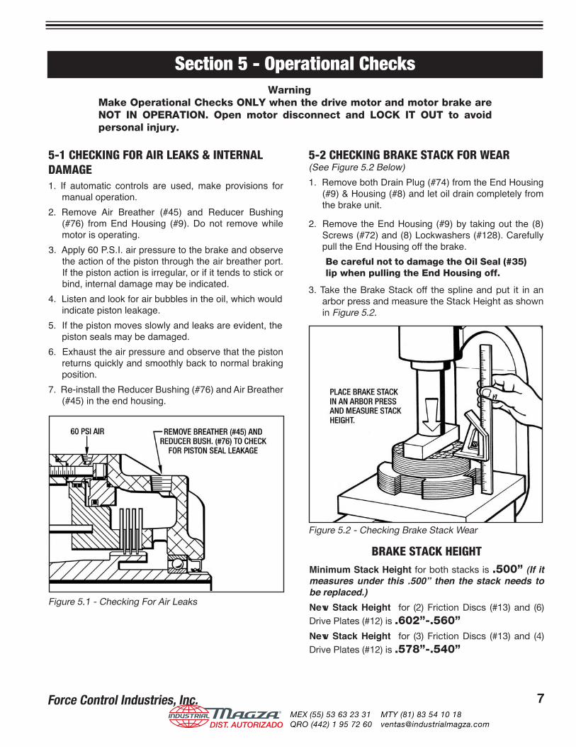
5-2 CHECKING BRAKE STACK FOR WEAR(See Figure 5.2 Below)1. Remove both Drain Plug (#74) from the End Housing
(#9) & Housing (#8) and let oil drain completely from the brake unit.
2. Remove the End Housing (#9) by taking out the (8) Screws (#72) and (8) Lockwashers (#128). Carefully pull the End Housing off the brake.Be careful not to damage the Oil Seal (#35) lip when pulling the End Housing off.
3. Take the Brake Stack off the spline and put it in an arbor press and measure the Stack Height as shown in Figure 5.2.
Figure 5.1 - Checking For Air Leaks
Figure 5.2 - Checking Brake Stack Wear
BRAKE STACK HEIGHTMinimum Stack Height for both stacks is .500” (If it measures under this .500” then the stack needs to be replaced.)New Stack Height for (2) Friction Discs (#13) and (6) Drive Plates (#12) is .602”-.560”New Stack Height for (3) Friction Discs (#13) and (4) Drive Plates (#12) is .578”-.540”
®
DIST. AUTORIZADOMEX (55) 53 63 23 31QRO (442) 1 95 72 60
MTY (81) 83 54 10 [email protected]
Force Control Industries, Inc.8 Force Control Industries, Inc. 9
Section 6 - Troubleshooting
A. Brake fails to engage properly. Piston Sticking or binding Disassemble to extent necessary to check for damaged parts.
Weak or broken springs. Replace as needed.
Air pressure not exhausting or Check air regulator valve and replace slow in exhausting. if necessary.
Worn friction surfaces. Check parts for wear and replace if necessary.
B. Brake engages too quickly. Low oil level. Check oil level and correct.
C. Noise and vibration. Improper or loose mounting Check mounting and correct if of brake and gear reducer. necessary. If partial disassembly is required refer to Section 6-Repair.
D. Brake fails to disengage Low air pressure. Increase air pressure. (35 PSI min.)
properly. Piston sticking or binding Disassemble to extent necessary to check for damaged parts.
Air regulator valve not Check valve operation and replace functioning properly. if necessary.
E. Unit overheats Brake not engaging or Refer to Problems A and D. (Over 225° F) disengaging properly causing. excessive slippage.
Improper oil level Check oil level & add or drain if necessary.
F. Oil leakage Oil seal lip damaged. Check for leakage around shaft. Replace oil seal or wear sleeve if necessary.
O-Ring seals. Tighten all external bolts. If leak continues, check for damage.
G. Leakage at breather. Oil level too high. Drain excess oil.
Damaged seal around piston. Disassemble and replace as necessary.
H. Brake does not repeat. Air pressure changed. Check and adjust air pressure.
*Oil temperature changed. Check temperature.
PROBLEM POSSIBLE CAUSE CORRECTION
* For installations that require precise starting and stopping, operating temperatures are important. Operating temperatures between 116° F and 165° F are recommended.
®
DIST. AUTORIZADOMEX (55) 53 63 23 31QRO (442) 1 95 72 60
MTY (81) 83 54 10 [email protected]
Force Control Industries, Inc.8 Force Control Industries, Inc. 9
Section 7 - Disassembly7-1 REMOVING THE BRAKE FOR REPAIR1. Turn-Off and Lock-Out the electrical power to the
Drive Motor, Control Valve and Driven Machinery. Disconnect pneumatic fittings from the brake.
2. Loosen the (5) Screws in the Locking Collar (#29) as per manufacturers instructions. (See Page 18)
3. Loosen and detach the Torque Arm Assembly from the Brake.
4. Slide the brake off of the shaft and move it to a suit-able work table.
5. Take the Locking Collar (#29) off of the brake.
6. Drain all the fluid from the brake. Save or discard as condition warrants. Take off the Sight Gauge (#46) and Air Breather (#45) for cleaning.
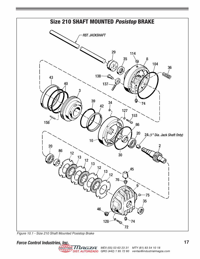
7-2 BRAKE DISASSEMBLY Refer to Figure 10.1 for a visual reference to all parts described in this Disassembly Procedure.
1. Set the brake in a vertical position with the End Hous-ing (#8) in an up position.
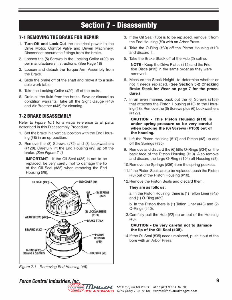
2. Remove the (8) Screws (#72) and (8) Lockwashers (#128). Carefully lift the End Housing (#9) up off the brake. (See Figure 7.1)
IMPORTANT - If the Oil Seal (#35) is not to be replaced, be very careful not to damage the lip of the Oil Seal (#35) when removing the End Housing (#9).
3. If the Oil Seal (#35) is to be replaced, remove it from the End Housing (#9) with an Arbor Press.
4. Take the O-Ring (#30) off the Piston Housing (#10) and discard it.
5. Take the Brake Stack off of the Hub (2) spline.
NOTE - Keep the Drive Plates (#12) and the Fric-tion Discs (#13) in the same order as they were removed.
6. Measure the Stack Height to determine whether or not it needs replaced. (See Section 5-2 Checking Brake Stack for Wear on page 7 for the proce-dure.)
7. In an even manner, back out the (6) Screws (#153) that attaches the Piston Housing (#10) to the Hous-ing (#8). Remove the (6) Screws plus (6) Lockwashers (#127).
CAUTION - This Piston Housing (#10) is under spring pressure so be very careful when backing the (6) Screws (#153) out of the housing.
8. Lift the Piston Housing (#10) and Piston (#3) up and off the Springs (#36).
9. Remove and discard the (6) little O-Rings (#34) on the back face of the Piston Housing (#10). Also remove and discard the large O-Ring (#104) off Housing (#8).
10. Remove the Springs (#36) from the spring pockets.
11. If the Piston Seals are to be replaced, push the Piston (#3) out of the Piston Housing (#10).
12. Remove the Piston Seals and discard them.
They are as follows: a. In the Piston Housing there is (1) Teflon Liner (#42)
and (1) O-Ring (#39).
b. In the Piston there is (1) Teflon Liner (#43) and (2) O-Rings (#40).
13. Carefully pull the Hub (#2) up an out of the Housing (#8).
CAUTION - Be very careful not to damage the lip of the Oil Seal (#35).
14. If the Oil Seal (#35) needs replaced, push it out of the bore with an Arbor Press.
Figure 7.1 - Removing End Housing (#8)
®
DIST. AUTORIZADOMEX (55) 53 63 23 31QRO (442) 1 95 72 60
MTY (81) 83 54 10 [email protected]
Force Control Industries, Inc.10 Force Control Industries, Inc. 11
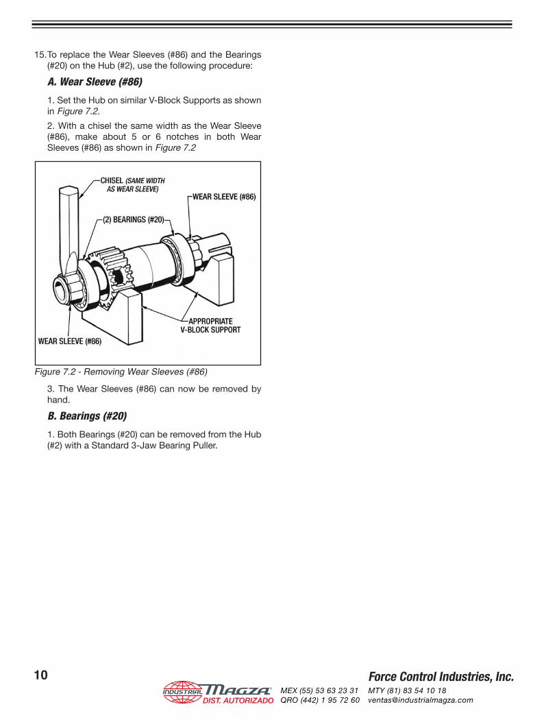
15. To replace the Wear Sleeves (#86) and the Bearings (#20) on the Hub (#2), use the following procedure:
A. Wear Sleeve (#86)
1. Set the Hub on similar V-Block Supports as shown in Figure 7.2.
2. With a chisel the same width as the Wear Sleeve (#86), make about 5 or 6 notches in both Wear Sleeves (#86) as shown in Figure 7.2
3. The Wear Sleeves (#86) can now be removed by hand.
B. Bearings (#20)
1. Both Bearings (#20) can be removed from the Hub (#2) with a Standard 3-Jaw Bearing Puller.
Figure 7.2 - Removing Wear Sleeves (#86)
®
DIST. AUTORIZADOMEX (55) 53 63 23 31QRO (442) 1 95 72 60
MTY (81) 83 54 10 [email protected]
Force Control Industries, Inc.10 Force Control Industries, Inc. 11
Section 8 - Cleaning, Inspection and Repair
8-1 GENERAL INFORMATIONRead and follow the safety precautions in Section 2 before performing any work on the Palletizer or the Posistop Brake or Worm Gear ReducerUnless the brake is to be completely overhauled, it should be disassembled only to the extent necessary to gain access to the worn or damaged parts
8-2 CLEANING AND INSPECTIONClean metal parts in a suitable solvent and dry with low pressure compressed air. The Drive Plates (#13) can be cleaned in a solvent, but DO NOT clean the Friction Discs (#12) in solvent. Use only a lint free rag to clean them. (Solvent will damage the friction material on the Friction Discs (#12). Keep the Brake Stack in the same order as they were removed. After cleaning, inspect parts for cracks, distortion, scoring, nicks, burrs or any other damage that would affect the operation of the unit.
Pay particular attention to the following.1. Check the friction discs wear surfaces for scoring,
galling or evidence of uneven wear.2. Check the brake drive plates for scoring or galling.
Make sure they are flat. If a perceptible ridge is worn in the drive plate where it mates with the friction disc, it should be replaced.
3. Carefully check the piston and bore surfaces for nicks, scratches, scoring or other damage, which would affect operation or cause leakage.
4. Pay particular attention to the oil seal and wear sleeves, checking for any nicks, scratches or any damage that would cause leakage.WARNING: Petroleum based cleaning solvents are extremely flammable. Open flames or smoking by any personnel in the vicinity of these solvents is extremely hazardous and MUST NOT BE PERMITTED.
8-3 REPAIR AND REPLACEMENTA fine stone or crocus cloth may be used to remove minor surface defects from parts if the operation or sealing action of the part is not affected. The use of coarser abrasives or other machining methods should not be attempted. Otherwise, damaged parts should be replaced.Replacement is recommended for the following parts when needed.1. Replace all O-Rings, Liners and Oil Seals removed
during disassembly.2. Replace brake discs and plates as a complete set.
®
DIST. AUTORIZADOMEX (55) 53 63 23 31QRO (442) 1 95 72 60
MTY (81) 83 54 10 [email protected]
Force Control Industries, Inc.12 Force Control Industries, Inc. 13
9-1 GENERAL REASSEMBLY INSTRUCTIONSNote the following general reassembly instructions as applicable:
1. Lubricate O-Rings, Liners and the lip of the Oil Seals with a light coating of Vaseline or white grease imme-diately before reassembly and installation of mating parts.
2. External Teflon Liners will be easier to install if heated in an oven to approx. 200° F. Max.
3. Heat the (2) Bearings (#20) in an oven to 250° F. to install them on the Hub (#2).
CAUTION - Use suitable gloves when han-dling heated parts.
4. Immediately before assembly, thoroughly clean all screw threads with Loctite Safety Solvent. At as-sembly apply Blue Loctite #242 (or equivalent) to all screw threads. Use this sparingly and wipe off any excess.
Basically the Reassembly Procedure is just the reverse order as the Disassembly Procedure
9-2 HUB REASSEMBLYIMPORTANT - The (2) Bearings (#20) have to be installed on the Hub (#2) before the (2) Wear Sleeves (#86).
1. Make sure all mating surfaces on the Hub (#2) are thoroughly cleaned before installation.
2. Lightly coat the mating surfaces of the Hub (#2) with Red Loctite #271.
3. Heat the (2) Bearings (#20) to 250° F. and drop them on the Hub (#2). Make sure each bearing is com-pletely seated against the shoulder.CAUTION - Always wear adequate gloves when handling heated parts.
4. Clean off any excess Loctite.
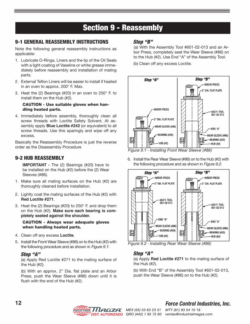
5. Install the Front Wear Sleeve (#86) on to the Hub (#2) with the following procedure and as shown in Figure 9.1:
Step “A” (a) Apply Red Loctite #271 to the mating surface of
the Hub (#2).
(b) With an approx. 2” Dia. flat plate and an Arbor Press, push the Wear Sleeve (#86) down until it is flush with the end of the Hub (#2).
Step “B” (a) With the Assembly Tool #601-02-013 and an Ar-
bor Press, completely seat the Wear Sleeve (#86) on to the Hub (#2). Use End “A” of the Assembly Tool.
(b) Clean off any excess Loctite.
6. Install the Rear Wear Sleeve (#86) on to the Hub (#2) with the following procedure and as shown in Figure 9.2:
Step “A” (a) Apply Red Loctite #271 to the mating surface of
the Hub (#2).
(b) With End “B” of the Assembly Tool #601-02-013, push the Wear Sleeve (#86) on to the Hub (#2).
Section 9 - Reassembly
Figure 9.1 - Installing Front Wear Sleeve (#86)
Figure 9.2 - Installing Rear Wear Sleeve (#86)
®
DIST. AUTORIZADOMEX (55) 53 63 23 31QRO (442) 1 95 72 60
MTY (81) 83 54 10 [email protected]
Force Control Industries, Inc.12 Force Control Industries, Inc. 13
Step “B” (a) With the End “A” of Assembly Tool #601-02-013
and an Arbor Press, completely seat the Wear Sleeve (#86) on to the Hub (#2).
(b) Clean off any excess Loctite.
See Page 15 for dimensions to make the Wear Sleeve Assembly Tool 601-02-013.
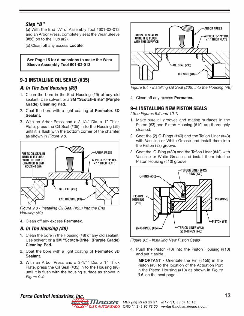
9-3 INSTALLING OIL SEALS (#35)
A. In The End Housing (#9)1. Clean the bore in the End Housing (#9) of any old
sealant. Use solvent or a 3M “Scotch-Brite” (Purple Grade) Cleaning Pad.
2. Coat the bore with a light coating of Permatex 3D Sealant.
3. With an Arbor Press and a 2-1/4” Dia. x 1” Thick Plate, press the Oil Seal (#35) in to the Housing (#9) until it is flush with the bottom corner of the chamfer as shown in Figure 9.3.
4. Clean off any excess Permatex.
B. In The Housing (#8)1. Clean the bore in the Housing (#8) of any old sealant.
Use solvent or a 3M “Scotch-Brite” (Purple Grade) Cleaning Pad.
2. Coat the bore with a light coating of Permatex 3D Sealant.
3. With an Arbor Press and a 3-1/4” Dia. x 1” Thick Plate, press the Oil Seal (#35) in to the Housing (#8) until it is flush with the housing surface as shown in Figure 9.4.
4. Clean off any excess Permatex.
9-4 INSTALLING NEW PISTON SEALS( See Figures 9.5 and 10.1)
1. Make sure all grooves and mating surfaces in the Piston (#3) and Piston Housing (#10) are thoroughly cleaned.
2. Coat the (2) O-Rings (#40) and the Teflon Liner (#43) with Vaseline or White Grease and install them into the Piston (#3) groove.
3. Coat the O-Ring (#39) and the Teflon Liner (#42) with Vaseline or White Grease and install them into the Piston Housing (#10) groove.
4. Push the Piston (#3) into the Piston Housing (#10) and set it aside.
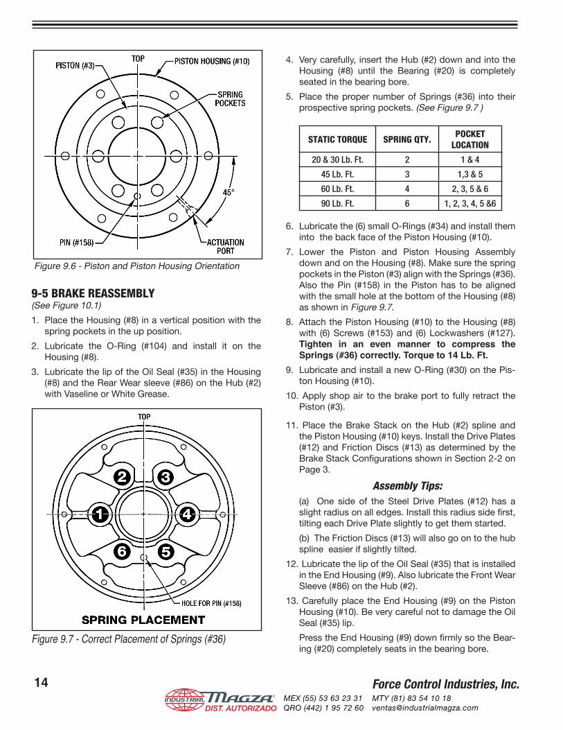
IMPORTANT - Orientate the Pin (#158) in the Piston (#3) to the location of the Actuation Port in the Piston Housing (#10) as shown in Figure 9.6. on the next page.
Figure 9.3 - Installing Oil Seal (#35) into the End Housing (#9)
Figure 9.4 - Installing Oil Seal (#35) into the Housing (#8)
Figure 9.5 - Installing New Piston Seals
®
DIST. AUTORIZADOMEX (55) 53 63 23 31QRO (442) 1 95 72 60
MTY (81) 83 54 10 [email protected]
Force Control Industries, Inc.14 Force Control Industries, Inc. 15
9-5 BRAKE REASSEMBLY(See Figure 10.1)
1. Place the Housing (#8) in a vertical position with the spring pockets in the up position.
2. Lubricate the O-Ring (#104) and install it on the Housing (#8).
3. Lubricate the lip of the Oil Seal (#35) in the Housing (#8) and the Rear Wear sleeve (#86) on the Hub (#2) with Vaseline or White Grease.
4. Very carefully, insert the Hub (#2) down and into the Housing (#8) until the Bearing (#20) is completely seated in the bearing bore.
5. Place the proper number of Springs (#36) into their prospective spring pockets. (See Figure 9.7 )
STATIC TORQUE SPRING QTY. POCKETLOCATION
20 & 30 Lb. Ft. 2 1 & 4
45 Lb. Ft. 3 1,3 & 5
60 Lb. Ft. 4 2, 3, 5 & 6
90 Lb. Ft. 6 1, 2, 3, 4, 5 &6
6. Lubricate the (6) small O-Rings (#34) and install them into the back face of the Piston Housing (#10).
7. Lower the Piston and Piston Housing Assembly down and on the Housing (#8). Make sure the spring pockets in the Piston (#3) align with the Springs (#36). Also the Pin (#158) in the Piston has to be aligned with the small hole at the bottom of the Housing (#8) as shown in Figure 9.7.
8. Attach the Piston Housing (#10) to the Housing (#8) with (6) Screws (#153) and (6) Lockwashers (#127). Tighten in an even manner to compress the Springs (#36) correctly. Torque to 14 Lb. Ft.
9. Lubricate and install a new O-Ring (#30) on the Pis-ton Housing (#10).
10. Apply shop air to the brake port to fully retract the Piston (#3).
11. Place the Brake Stack on the Hub (#2) spline and the Piston Housing (#10) keys. Install the Drive Plates (#12) and Friction Discs (#13) as determined by the Brake Stack Configurations shown in Section 2-2 on Page 3.
Assembly Tips: (a) One side of the Steel Drive Plates (#12) has a
slight radius on all edges. Install this radius side first, tilting each Drive Plate slightly to get them started.
(b) The Friction Discs (#13) will also go on to the hub spline easier if slightly tilted.
12. Lubricate the lip of the Oil Seal (#35) that is installed in the End Housing (#9). Also lubricate the Front Wear Sleeve (#86) on the Hub (#2).
13. Carefully place the End Housing (#9) on the Piston Housing (#10). Be very careful not to damage the Oil Seal (#35) lip.
Press the End Housing (#9) down firmly so the Bear-ing (#20) completely seats in the bearing bore.
Figure 9.7 - Correct Placement of Springs (#36)
Figure 9.6 - Piston and Piston Housing Orientation
®
DIST. AUTORIZADOMEX (55) 53 63 23 31QRO (442) 1 95 72 60
MTY (81) 83 54 10 [email protected]
Force Control Industries, Inc.14 Force Control Industries, Inc. 15
Section 10 - Ordering Repair Parts10-1 Ordering Repair PartsWhen ordering any repair parts, please specify all of the following information.1. COMPLETE MODEL NUMBER (On Name Plate)2. SERIAL NUMBER (On Name Plate)3. PART REFERENCE NUMBER (From Parts List and
Exploded View Drawing)4. PART NAME (From Parts List)5. QUANTITY (As Required)6. COMPLETE SHIPPING INFORMATIONIMPORTANT - Failure to include all of the above information will delay your parts order. Unless another method is specified for shipping information, parts weighing less than 70 Ibs. will be shipped United Parcel Service. Parts weighing over 70 Ibs. will be shipped motor freight. Airfreight and other transportation services are available, but only if specified on your order
10-2 Factory Rebuild ServiceReconditioning Service is offered by Force Control Industries at the factory. Before returning a unit for this service, be sure to first contact the Service Sales Department at Force Control Industries for authorization and shipping instructions. Force Control cannot be responsible for any units returned to the factory without prior notice and authorization.Care must be given to the packaging of returned units. Always protect mounting feet and flanges by attaching to a suitable skid. Damaged units always delay repairs. It is usually impossible to recover damage costs from the carrier.Whenever possible describe the problems you are having with your unit on your shipping papers.Return to:
Force Control Industries, Inc.3660 Dixie HighwayFairfield, Ohio 45014Telephone: 513-868-0900Fax: 513-868-2105E-Mail: [email protected]
Dimensions are given for this Wear Sleeve Assembly Tool in case you prefer to make your own. It can also be ordered from Force Control with this part number 601-02-013
9-6 WEAR SLEEVE ASSEMBLY TOOL DIMENSIONS14. Attach with (8) Screws (#72) and (8) Lockwashers (#128). Torque to 14 Lb. Ft.
15. Reinstall the Sight Gauge (#46), Air Breather (#45) and any other pipe plugs or fittings removed for Disassembly.
16. Fill with fresh oil as described in Section 4 - Lu-brication.
17. Check the operation of the brake as per instruc-tions given in Section 5 - Operational Checks.
18. Reinstall the Brake back on the Driven/Jack Shaft with the same procedure given in Section 3 - In-stallation.
Figure 9.8 - Wear Sleeve Assembly Tool
®
DIST. AUTORIZADOMEX (55) 53 63 23 31QRO (442) 1 95 72 60
MTY (81) 83 54 10 [email protected]
Force Control Industries, Inc.16 Force Control Industries, Inc. 17
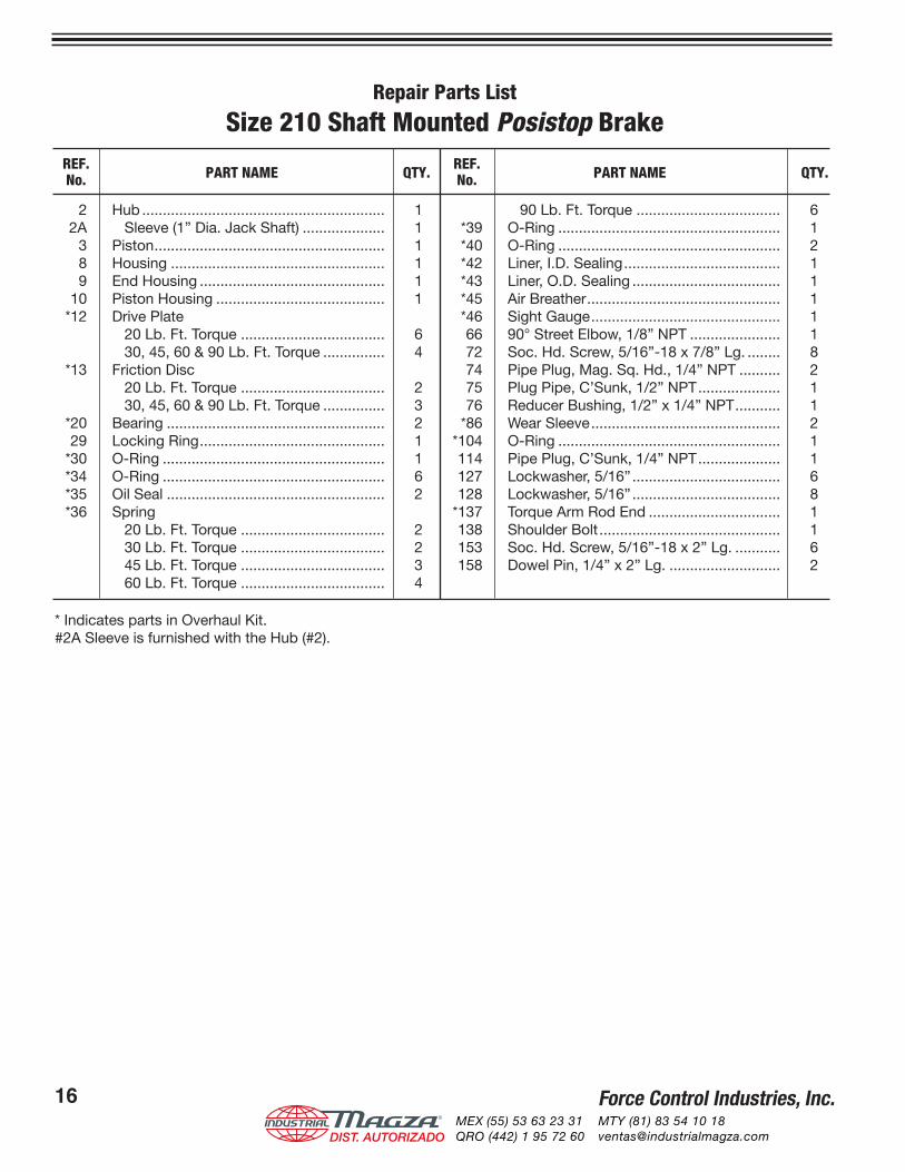
Repair Parts List
Size 210 Shaft Mounted Posistop Brake
2 Hub ........................................................... 1 2A Sleeve (1” Dia. Jack Shaft) .................... 1 3 Piston........................................................ 1 8 Housing .................................................... 1 9 End Housing ............................................. 1 10 Piston Housing ......................................... 1 *12 Drive Plate 20 Lb. Ft. Torque ................................... 6 30, 45, 60 & 90 Lb. Ft. Torque ............... 4 *13 Friction Disc 20 Lb. Ft. Torque ................................... 2 30, 45, 60 & 90 Lb. Ft. Torque ............... 3 *20 Bearing ..................................................... 2 29 Locking Ring............................................. 1 *30 O-Ring ...................................................... 1 *34 O-Ring ...................................................... 6 *35 Oil Seal ..................................................... 2 *36 Spring 20 Lb. Ft. Torque ................................... 2 30 Lb. Ft. Torque ................................... 2 45 Lb. Ft. Torque ................................... 3 60 Lb. Ft. Torque ................................... 4
90 Lb. Ft. Torque ................................... 6 *39 O-Ring ...................................................... 1 *40 O-Ring ...................................................... 2 *42 Liner, I.D. Sealing...................................... 1 *43 Liner, O.D. Sealing .................................... 1 *45 Air Breather............................................... 1 *46 Sight Gauge.............................................. 1 66 90° Street Elbow, 1/8” NPT ...................... 1 72 Soc. Hd. Screw, 5/16”-18 x 7/8” Lg. ........ 8 74 Pipe Plug, Mag. Sq. Hd., 1/4” NPT .......... 2 75 Plug Pipe, C’Sunk, 1/2” NPT.................... 1 76 Reducer Bushing, 1/2” x 1/4” NPT........... 1 *86 Wear Sleeve.............................................. 2 *104 O-Ring ...................................................... 1 114 Pipe Plug, C’Sunk, 1/4” NPT.................... 1 127 Lockwasher, 5/16”.................................... 6 128 Lockwasher, 5/16”.................................... 8 *137 Torque Arm Rod End ................................ 1 138 Shoulder Bolt............................................ 1 153 Soc. Hd. Screw, 5/16”-18 x 2” Lg. ........... 6 158 Dowel Pin, 1/4” x 2” Lg. ........................... 2
REF. PART NAME QTY. REF. PART NAME QTY. No. No.
* Indicates parts in Overhaul Kit.#2A Sleeve is furnished with the Hub (#2).
®
DIST. AUTORIZADOMEX (55) 53 63 23 31QRO (442) 1 95 72 60
MTY (81) 83 54 10 [email protected]
Force Control Industries, Inc.16 Force Control Industries, Inc. 17
Size 210 SHAFT MOUNTED Posistop BRAKE
Figure 10.1 - Size 210 Shaft Mounted Posistop Brake
®
DIST. AUTORIZADOMEX (55) 53 63 23 31QRO (442) 1 95 72 60
MTY (81) 83 54 10 [email protected]
Force Control Industries, Inc.18®
DIST. AUTORIZADOMEX (55) 53 63 23 31QRO (442) 1 95 72 60
MTY (81) 83 54 10 [email protected]

Force Control Industries, Inc.18®
DIST. AUTORIZADOMEX (55) 53 63 23 31QRO (442) 1 95 72 60
MTY (81) 83 54 10 [email protected]

FORCE CONTROL INDUSTRIES, INC.
Worldwide Leader In Oil Shear Technology
Providing todayʼs industries withOil Shear Clutch/Brake Drives
and Servo Systemsthat delivers:
Flexibility • EfficiencyEndurance • Performance
Dependability
“Built to Last - Guaranteed to Perform”
FORCE CONTROL INDUSTRIES, INC.
P.O. Box 18366Fairfield, Ohio 45018
3660 Dixie HighwayFairfield, Ohio 45014
Tel: 1-513-868-0900Toll Free: 1-800-869-3244
Fax: 1-513-868-2105
E-Mail: [email protected] Site: www.forcecontrol.com
®
DIST. AUTORIZADOMEX (55) 53 63 23 31QRO (442) 1 95 72 60
MTY (81) 83 54 10 [email protected]