Embed Size (px)
Citation preview
Engineering Manual
Section 2556
Water Distribution Systems
PART 1: General
1.1 General Description of Work - The contractor shall furnish and install all pipes, fittings, structures and accessories required for water transmission, distribution and/or service lines in accordance with the requirements of the Construction Plans and related Contract Documents.
1.2 Commonly Used Acronyms –
ANSI American National Standards Institute ASME American Society of Mechanical Engineers ASSE American Society of Safety Engineers ASTM American Society for Testing and Materials AWWA American Water Works Association
CA Concrete Asbestos CI Cast Iron DI Ductile Iron
DIPS Ductile Iron Pipe Standard ECUA Emerald Coast Utilities Authority FAC Florida Administrative Code
FDEP Florida Department of Environmental Protection FLG Flange
HDPE High-Density Polyethylene MJ Mechanical Joint
MSS Manufacturer's Standardization Society NSF National Standards Foundation OD Outside Diameter PVC Polyvinyl Chloride SBR Styrene Butadiene Rubber SF Suction Flange
10/1/14 Section 2556 – Water Distribution Systems Page 1 of 32
Engineering Manual
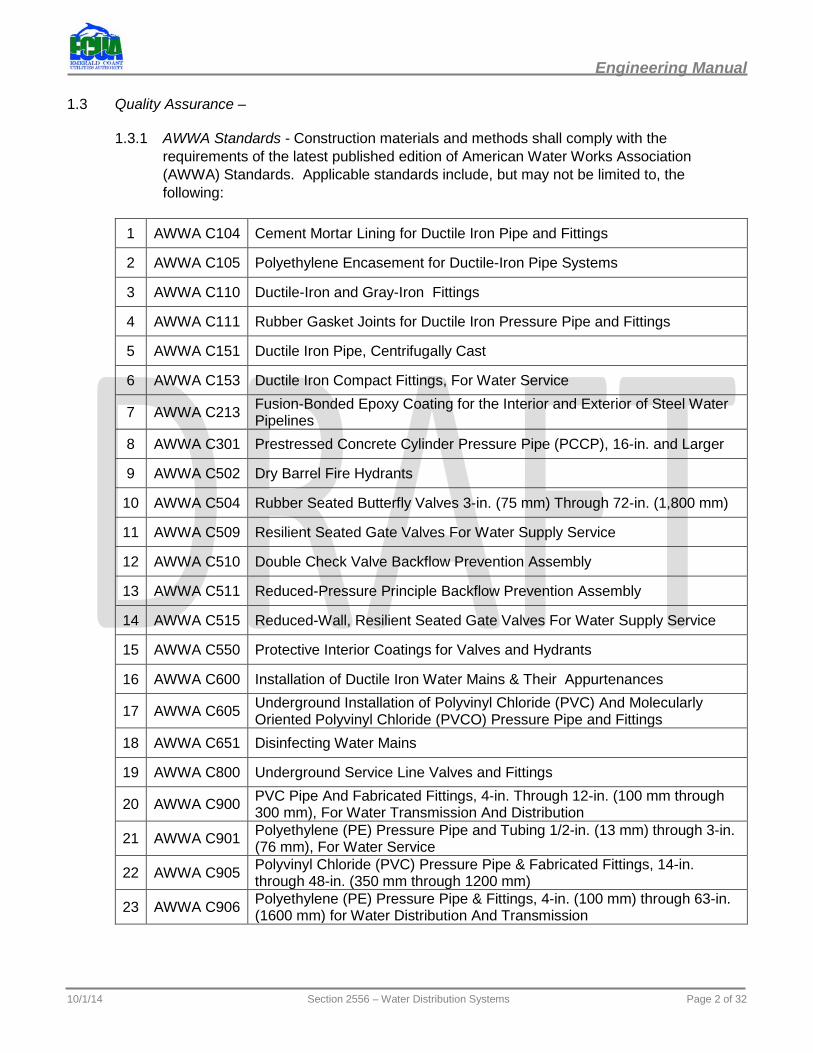
1.3 Quality Assurance –
1.3.1 AWWA Standards - Construction materials and methods shall comply with the requirements of the latest published edition of American Water Works Association (AWWA) Standards. Applicable standards include, but may not be limited to, the following:
1 AWWA C104 Cement Mortar Lining for Ductile Iron Pipe and Fittings
2 AWWA C105 Polyethylene Encasement for Ductile-Iron Pipe Systems
3 AWWA C110 Ductile-Iron and Gray-Iron Fittings
4 AWWA C111 Rubber Gasket Joints for Ductile Iron Pressure Pipe and Fittings
5 AWWA C151 Ductile Iron Pipe, Centrifugally Cast
6 AWWA C153 Ductile Iron Compact Fittings, For Water Service
7 AWWA C213 Fusion-Bonded Epoxy Coating for the Interior and Exterior of Steel Water Pipelines
8 AWWA C301 Prestressed Concrete Cylinder Pressure Pipe (PCCP), 16-in. and Larger
9 AWWA C502 Dry Barrel Fire Hydrants
10 AWWA C504 Rubber Seated Butterfly Valves 3-in. (75 mm) Through 72-in. (1,800 mm)
11 AWWA C509 Resilient Seated Gate Valves For Water Supply Service
12 AWWA C510 Double Check Valve Backflow Prevention Assembly
13 AWWA C511 Reduced-Pressure Principle Backflow Prevention Assembly
14 AWWA C515 Reduced-Wall, Resilient Seated Gate Valves For Water Supply Service
15 AWWA C550 Protective Interior Coatings for Valves and Hydrants
16 AWWA C600 Installation of Ductile Iron Water Mains & Their Appurtenances
17 AWWA C605 Underground Installation of Polyvinyl Chloride (PVC) And Molecularly Oriented Polyvinyl Chloride (PVCO) Pressure Pipe and Fittings
18 AWWA C651 Disinfecting Water Mains
19 AWWA C800 Underground Service Line Valves and Fittings
20 AWWA C900 PVC Pipe And Fabricated Fittings, 4-in. Through 12-in. (100 mm through 300 mm), For Water Transmission And Distribution
21 AWWA C901 Polyethylene (PE) Pressure Pipe and Tubing 1/2-in. (13 mm) through 3-in. (76 mm), For Water Service
22 AWWA C905 Polyvinyl Chloride (PVC) Pressure Pipe & Fabricated Fittings, 14-in. through 48-in. (350 mm through 1200 mm)
23 AWWA C906 Polyethylene (PE) Pressure Pipe & Fittings, 4-in. (100 mm) through 63-in. (1600 mm) for Water Distribution And Transmission
10/1/14 Section 2556 – Water Distribution Systems Page 2 of 32
Engineering Manual
1.3.2 ASTM and NSF Standards - In addition, construction materials and methods shall also comply with the requirements of the latest published editions of the American Society for Testing and Materials (ASTM) Standards, and the National Sanitation Foundation (NSF) Standard 61.
1 ASTM A126 Standard Specification for Gray Iron Castings for Valves, Flanges, and Pipe Fittings
2 ASTM A48 Standard Specification for Gray Iron Castings
3 ASTM B584 Standard Specification for Copper Allow Sand Castings for General Applications
4 ASTM B62 Standard Specification for Composition Bronze or Ounce Metal Castings
5 ASTM B88 Standard Specification for Seamless Copper Water Tube
6 ASTM D1248 Standard Specification for Polyethylene Plastics Extrusion Materials for Wire and Cable
7 ASTM D1598 Standard Test Method for Time-to-Failure of Plastic Pipe Under Constant Internal Pressure
8 ASTM D1599 Standard Test Method for Resistance to Short-Time Hydraulic Pressure of Plastic Pipe, Tubing, and Fittings
9 ASTM D1693 Standard Test Method for Environmental Stress-Cracking of Ethylene Plastics
10 ASTM D2241 Standard Specification for Poly (Vinyl Chloride) (PVC) Pressure-Rated Pipe (SDR Series)
11 ASTM D2737 Standard Specification for Polyethylene (PE) Plastic Tubing
12 ASTM D3350 Standard Specification for Polyethylene Plastics Pipe and Fittings Materials
13 ASTM D429 Standard Test Methods for Rubber Property-Adhesion to Rigid Substrates
14 ASTM F477 Standards Specification for Elastomeric Seals (Gaskets) for Joining Plastic Pipe
1.3.3 ASME and ANSI Standards - In addition, construction materials and methods shall also comply with the requirements of the latest published editions of the American Society of Mechanical Engineers (ASME) Standards, and the American National Standards Institute (ANSI).
1 ASME/ANSI B16.20
Metallic Gaskets for Pipe Flanges: Ring-Joint, Spiral-Wound, and Jacketed
2 ASME/ANSI B16.1
Gray Iron Pipe Flanges and Flanged Fittings: Classes 25, 125, and 250
3 ASME/ANSI B 1.1 Unified Inch Screw Threads, UN and UNR Thread Form
4 ASME/ANSI B 1.20.1 Pipe Threads, General Purpose (Inch)
5 ASME/ANSI B 1.20.3 Dryseal Pipe Threads (Inch)
10/1/14 Section 2556 – Water Distribution Systems Page 3 of 32
Engineering Manual
PART 2: Materials and Equipment
2.1 General - All pipe, fittings and accessories shall be new, and shall be suitable and rated for potable water use. All pipe, fittings and accessories shall be rated for a pressure of 160 psi or greater. All water pipe and fittings shall be color coded blue in accordance with FDEP and AWWA requirements, and FAC 62-555.320.
2.2 Delivery, Storage, and Handling - Certificates of Compliance with the Specifications may be required for all materials used on the Project. All materials are to be transported, stored, handled, and installed in accordance with the manufacturer’s recommendations to avoid physical damage. All materials shall be stored to prevent physical deterioration due to sun and weather. The ECUA reserves the right to reject material which in any way does not meet the requirements of these Specifications.
2.3 Water Mains –
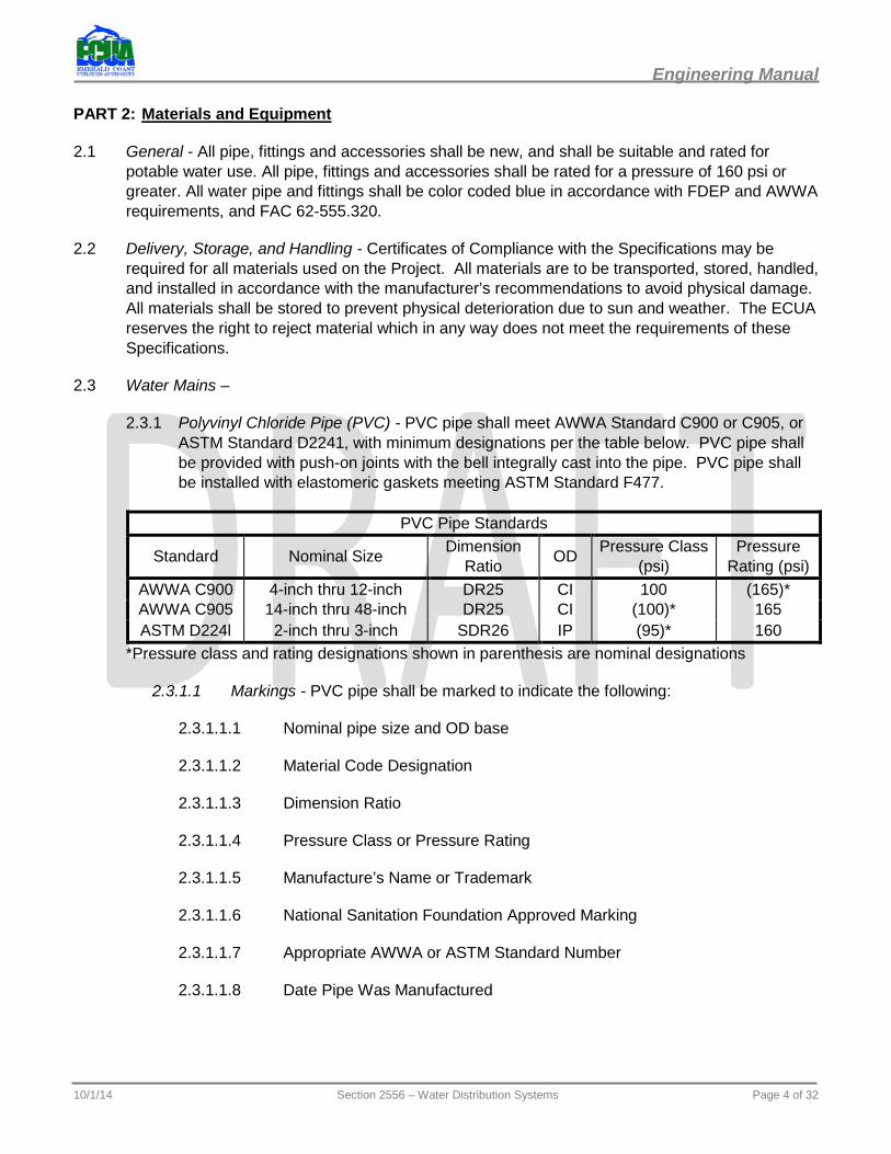
2.3.1 Polyvinyl Chloride Pipe (PVC) - PVC pipe shall meet AWWA Standard C900 or C905, or ASTM Standard D2241, with minimum designations per the table below. PVC pipe shall be provided with push-on joints with the bell integrally cast into the pipe. PVC pipe shall be installed with elastomeric gaskets meeting ASTM Standard F477.
PVC Pipe Standards
Standard Nominal Size Dimension Ratio OD Pressure Class
(psi) Pressure
Rating (psi) AWWA C900 4-inch thru 12-inch DR25 CI 100 (165)* AWWA C905 14-inch thru 48-inch DR25 CI (100)* 165 ASTM D224l 2-inch thru 3-inch SDR26 IP (95)* 160
*Pressure class and rating designations shown in parenthesis are nominal designations
2.3.1.1 Markings - PVC pipe shall be marked to indicate the following:
2.3.1.1.1 Nominal pipe size and OD base
2.3.1.1.2 Material Code Designation
2.3.1.1.3 Dimension Ratio
2.3.1.1.4 Pressure Class or Pressure Rating
2.3.1.1.5 Manufacture’s Name or Trademark
2.3.1.1.6 National Sanitation Foundation Approved Marking
2.3.1.1.7 Appropriate AWWA or ASTM Standard Number
2.3.1.1.8 Date Pipe Was Manufactured
10/1/14 Section 2556 – Water Distribution Systems Page 4 of 32
Engineering Manual
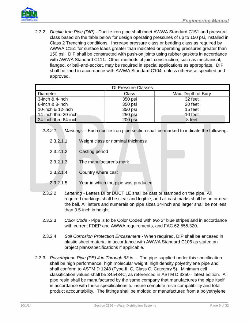
2.3.2 Ductile Iron Pipe (DIP) - Ductile iron pipe shall meet AWWA Standard C151 and pressure class based on the table below for design operating pressures of up to 150 psi, installed in Class 2 Trenching conditions. Increase pressure class or bedding class as required by AWWA C151 for surface loads greater than indicated or operating pressures greater than 150 psi. DIP shall be constructed with push-on joints using rubber gaskets in accordance with AWWA Standard C111. Other methods of joint construction, such as mechanical, flanged, or ball-and-socket, may be required in special applications as appropriate. DIP shall be lined in accordance with AWWA Standard C104, unless otherwise specified and approved.
DI Pressure Classes Diameter Class Max. Depth of Bury 3-inch & 4-inch 350 psi 32 feet 6-inch & 8-inch 350 psi 20 feet 10-inch & 12-inch 350 psi 15 feet 14-inch thru 20-inch 250 psi 10 feet 24-inch thru 64-inch 200 psi 8 feet
2.3.2.1 Markings – Each ductile iron pipe section shall be marked to indicate the following:
2.3.2.1.1 Weight class or nominal thickness
2.3.2.1.2 Casting period
2.3.2.1.3 The manufacturer’s mark
2.3.2.1.4 Country where cast
2.3.2.1.5 Year in which the pipe was produced
2.3.2.2 Lettering - Letters DI or DUCTILE shall be cast or stamped on the pipe. All required markings shall be clear and legible, and all cast marks shall be on or near the bell. All letters and numerals on pipe sizes 14-inch and larger shall be not less than 0.5-inch in height.
2.3.2.3 Color Code - Pipe is to be Color Coded with two 2” blue stripes and in accordance with current FDEP and AWWA requirements, and FAC 62-555.320.
2.3.2.4 Soil Corrosion Protection Encasement - When required, DIP shall be encased in plastic sheet material in accordance with AWWA Standard C105 as stated on project plans/specifications if applicable.
2.3.3 Polyethylene Pipe (PE) 4 in Through 63 in. - The pipe supplied under this specification shall be high performance, high molecular weight, high density polyethylene pipe and shall conform to ASTM D 1248 (Type III C, Class C, Category 5). Minimum cell classification values shall be 345434C, as referenced in ASTM D 3350 - latest edition. All pipe resin shall be manufactured by the same company that manufactures the pipe itself in accordance with these specifications to insure complete resin compatibility and total product accountability. The fittings shall be molded or manufactured from a polyethylene
10/1/14 Section 2556 – Water Distribution Systems Page 5 of 32
Engineering Manual
compound having a cell classification equal to or exceeding the compound used in the pipe. To insure compatibility of polyethylene resins, all fittings supplied under this specification shall be of the same manufacturer as the pipe being supplied.
2.3.3.1 Quality Control – Refer to the following guidelines regarding quality control.
2.3.3.1.1 The resin used to manufacture the pipe shall be produced by the pipe manufacturer, thus maintaining complete control of the pipe quality. The pipe shall contain no recycled compound except that generated in the manufacturer’s own plant from resin of the same specification and from the same raw material. The pipe shall be homogeneous throughout and free of visible cracks, holes, foreign inclusions, or other deleterious defects, and shall be identical in color, density, melt index, and other physical properties.
2.3.3.1.2 The Engineer may request, as part of the quality control records submittal, certification that the pipe produced is represented by the quality assurance testing. Additionally, test results from manufacturer’s testing or random manufacturer’s representation, may be cause for rejection of pipe represented by the testing. These tests may include density and flow rate measurements from samples taken at selected locations within the pipe wall and thermal stability determinations according to ASTM D 3350, 10.1.9.
2.3.3.1.2.1 Verification - The owner or the specifying Engineer may request certified lab data to verify the physical properties of the materials supplied under this specification or may take random samples and have them tested by an independent laboratory.
2.3.3.1.2.2 Rejection - Polyethylene pipe and fittings may be rejected for failure to meet any of the requirements of this specification.
2.3.3.1.2.3 Pipe dimensions - Refer to the following guidelines regarding pipe dimensions:
2.3.3.1.2.3.1 3” polyethylene pipe for water main installation supplied under this specification shall have nominal IPS O.D. size unless otherwise specified. Pipe shall have a SDR of 11 unless otherwise specified.
2.3.3.1.2.3.2 4” and larger - Pipe supplied under this specification shall have a nominal DIPS O.D. unless otherwise specified. Pipe shall have a SDR of 11 unless otherwise specified.
2.3.3.2 Color Coding – HDPE water pipe shall be color-coded with a minimum of two 2” wide blue stripes or have an integral, extruded blue coating. Color coding shall be in accordance with FDEP and AWWA requirements, and FAC 62-555.320
2.3.3.3 Approved Manufacturers - Approved manufacturers shall be approved by ECUA in writing.
10/1/14 Section 2556 – Water Distribution Systems Page 6 of 32
Engineering Manual
2.3.4 Alternate Pipe Materials - ECUA may consider other pipe materials as appropriate for the needs of the Project. Alternate pipe materials identified during design and approved for use on the Project shall be noted on the Construction Plans, and a detailed Technical Specification shall be prepared and included in the Contract Documents.
2.4 Water Main Appurtenances –
2.4.1 Water Main Fittings –
2.4.1.1 PVC or Ductile Iron Pipe Fittings - Water main fittings shall include Tees, Wyes, Bends, Reducers, and other appurtenances commonly used in pipe construction. Fittings shall be ductile iron meeting AWWA Standard C110 or C153 with pressure ratings of not less than that specified for adjacent pipe. Fittings shall be constructed with mechanical joints, unless otherwise specified, and shall be supplied complete with low alloy bolts and nuts, SBR gaskets and other necessary parts required for field assembly. Fittings shall be cement-mortar lined in accordance with AWWA Standard C104/A21.4.
2.4.1.2 HDPE Pipe Fittings - Refer to the following guidelines regarding water main fittings:
2.4.1.2.1 Mechanical connections of HDPE pipe sized under 4” to ductile iron or PVC piping, mechanical joint fittings, or valves shall be through a self-restraining, fusible mechanical joint adapter. Mechanical joint adapter shall be the same SDR rating as the pipe. Provide the mechanical joint adapter, including but not limited to longer tee bolts and all thread rods with nuts at the mechanical joint bell. Transition fittings of HDPE by male iron pipe threaded end installed by butt fusion may be used.
2.4.1.2.2 Mechanical connections of HDPE pipe (4” and larger) to ductile iron or PVC piping, mechanical joint fittings, or valves shall be through the use of the above specified mechanical joint adapter if available.
2.4.1.3 Pipe Couplings – Refer to the following guidelines regarding pipe couplings:
2.4.1.3.1 Pipe couplings shall be solid sleeve type with mechanical joints at each end containing a compression gasket. Couplings shall be ductile iron, 12 inches minimum in length, with low alloy bolts and nuts, and SBR gaskets. Rings and gaskets shall be sized to conform exactly to the requirements of the pipe manufacturer.
2.4.1.3.2 For transition between asbestos cement and PVC or DI pipe types, Hymax 2000 Series, Romac Macro HP, Couplings, or ECUA approved equal, shall be used.
2.4.1.3.3 Polyethylene pipe and fittings may be joined using approved electro fusion couplings. Fittings shall be PE3408 HDPE. Electro fusion fittings shall have a pressure rating equal to the pipe.
10/1/14 Section 2556 – Water Distribution Systems Page 7 of 32
Engineering Manual
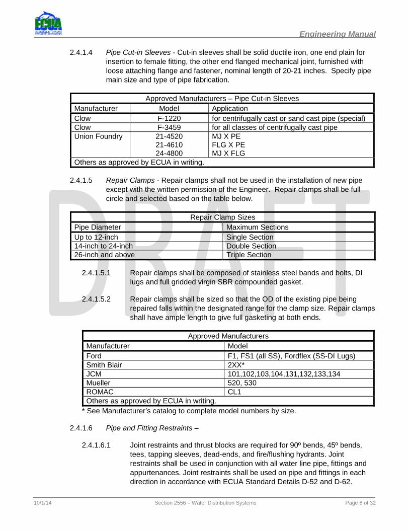
2.4.1.4 Pipe Cut-in Sleeves - Cut-in sleeves shall be solid ductile iron, one end plain for insertion to female fitting, the other end flanged mechanical joint, furnished with loose attaching flange and fastener, nominal length of 20-21 inches. Specify pipe main size and type of pipe fabrication.
Approved Manufacturers – Pipe Cut-in Sleeves Manufacturer Model Application Clow F-1220 for centrifugally cast or sand cast pipe (special) Clow F-3459 for all classes of centrifugally cast pipe Union Foundry 21-4520
21-4610 24-4800
MJ X PE FLG X PE MJ X FLG
Others as approved by ECUA in writing.
2.4.1.5 Repair Clamps - Repair clamps shall not be used in the installation of new pipe except with the written permission of the Engineer. Repair clamps shall be full circle and selected based on the table below.
Repair Clamp Sizes Pipe Diameter Maximum Sections Up to 12-inch Single Section 14-inch to 24-inch Double Section 26-inch and above Triple Section
2.4.1.5.1 Repair clamps shall be composed of stainless steel bands and bolts, DI lugs and full gridded virgin SBR compounded gasket.
2.4.1.5.2 Repair clamps shall be sized so that the OD of the existing pipe being repaired falls within the designated range for the clamp size. Repair clamps shall have ample length to give full gasketing at both ends.
Approved Manufacturers Manufacturer Model Ford F1, FS1 (all SS), Fordflex (SS-DI Lugs) Smith Blair 2XX* JCM 101,102,103,104,131,132,133,134 Mueller 520, 530 ROMAC CL1 Others as approved by ECUA in writing.
* See Manufacturer’s catalog to complete model numbers by size.
2.4.1.6 Pipe and Fitting Restraints –
2.4.1.6.1 Joint restraints and thrust blocks are required for 90º bends, 45º bends, tees, tapping sleeves, dead-ends, and fire/flushing hydrants. Joint restraints shall be used in conjunction with all water line pipe, fittings and appurtenances. Joint restraints shall be used on pipe and fittings in each direction in accordance with ECUA Standard Details D-52 and D-62.
10/1/14 Section 2556 – Water Distribution Systems Page 8 of 32

Engineering Manual
2.4.1.6.2 Restraints shall have set or anchor screws used to secure body to pipe with torque limit break away head design. Alternately, fittings with integral restraint mechanisms (“One-Bolt”) may be used with the approval of the ECUA Engineer.
Approved Manufacturers Manufacturer Model Ebaa Iron Works MegaLug Series 1100, 1500, 2000, 2500, 3000, 3600, 6500 Ford UNI-Flange UAI, UBI, UI, 1300, 1340, 1390, 1400 JCM Industries Sur-Grip Restrainers No. 620, 621 Sigma SLC, SLD, PVP Star Pipe Products Series 3000 for 3” – 48” ductile iron One Bolt (with approval of ECUA Engineer)
ROMAC Grip Ring / Roma Grip / 600 series Tyler Union TufGrip Others as approved by ECUA in writing.
2.4.1.7 Expansion Joints - Refer to the following guidelines regarding expansion joints:
2.4.1.7.1 Expansion joint fittings shall be used where specified on the Construction Plans. They shall be of the rigid or flexible type as specified, and manufactured of ductile iron in accordance with the table in Section 2.4.1.5. They shall be capable of expanding or contracting to the extent specified by the Engineer, but in no case less than 4-inches axially, and designed to prevent separation beyond the maximum extension without the use of external tie rods.
2.4.1.7.2 Fittings shall be flanged or provided with restrained mechanical joints, individually pressure tested to a minimum of 350 psi against their own restraints, and internally coated on all exposed surfaces with a minimum of 15 millimeters of fusion bonded epoxy conforming to AWWA C116. They shall be capable of deflecting at least 15º by means of an integral ball at each joint in the case of flexible types.
Approved Manufacturers Type Manufacturer Model Rigid EBAA Iron, Inc. EX-TEND 200 Flexible EBAA Iron, Inc. Flex-Tend Others as approved by ECUA in writing.
2.4.1.8 Tapping Sleeves - Refer to the following guidelines regarding tapping sleeves:
2.4.1.8.1 The minimum size tapping sleeve shall be 4”. Connection of 3” lines to existing pipes 4” and larger shall be made by a 4” tapping sleeve with appropriate reducing fitting. Tapping saddles shall be used for smaller connections.
10/1/14 Section 2556 – Water Distribution Systems Page 9 of 32
Engineering Manual
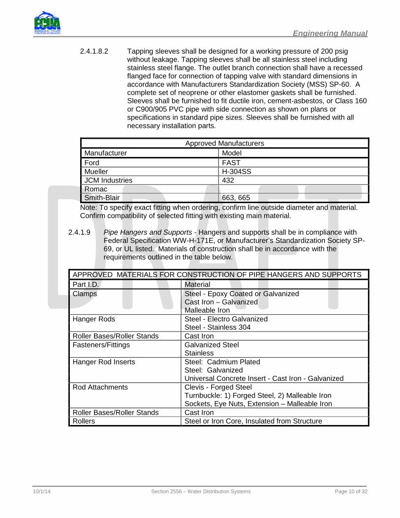
2.4.1.8.2 Tapping sleeves shall be designed for a working pressure of 200 psig without leakage. Tapping sleeves shall be all stainless steel including stainless steel flange. The outlet branch connection shall have a recessed flanged face for connection of tapping valve with standard dimensions in accordance with Manufacturers Standardization Society (MSS) SP-60. A complete set of neoprene or other elastomer gaskets shall be furnished. Sleeves shall be furnished to fit ductile iron, cement-asbestos, or Class 160 or C900/905 PVC pipe with side connection as shown on plans or specifications in standard pipe sizes. Sleeves shall be furnished with all necessary installation parts.
Approved Manufacturers Manufacturer Model Ford FAST Mueller H-304SS JCM Industries 432 Romac Smith-Blair 663, 665
Note: To specify exact fitting when ordering, confirm line outside diameter and material. Confirm compatibility of selected fitting with existing main material.
2.4.1.9 Pipe Hangers and Supports - Hangers and supports shall be in compliance with Federal Specification WW-H-171E, or Manufacturer’s Standardization Society SP-69, or UL listed. Materials of construction shall be in accordance with the requirements outlined in the table below.
APPROVED MATERIALS FOR CONSTRUCTION OF PIPE HANGERS AND SUPPORTS Part I.D. Material Clamps Steel - Epoxy Coated or Galvanized Cast Iron – Galvanized Malleable Iron Hanger Rods Steel - Electro Galvanized Steel - Stainless 304 Roller Bases/Roller Stands Cast Iron Fasteners/Fittings Galvanized Steel Stainless Hanger Rod Inserts Steel: Cadmium Plated Steel: Galvanized Universal Concrete Insert - Cast Iron - Galvanized Rod Attachments Clevis - Forged Steel Turnbuckle: 1) Forged Steel, 2) Malleable Iron Sockets, Eye Nuts, Extension – Malleable Iron Roller Bases/Roller Stands Cast Iron Rollers Steel or Iron Core, Insulated from Structure
10/1/14 Section 2556 – Water Distribution Systems Page 10 of 32
Engineering Manual
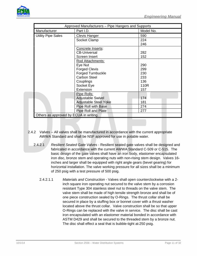
Approved Manufacturers – Pipe Hangers and Supports Manufacturer Part I.D. Model No. Utility Pipe Sales Clevis Hanger 590 Socket Clamp 224 246 Concrete Inserts:
CB-Universal Screen Insert
282 152
Rod Attachments: Eye Nut Forged Clevis Forged Turnbuckle Carbon Steel Couplings Socket Eye Extension
290 299 230 233 136 110R 157
Pipe Rolls: Adjustable Swivel Adjustable Steel Yoke
174 181
Pipe Roll with Base 274 Pipe Roll and Plate 277 Others as approved by ECUA in writing.
2.4.2 Valves – All valves shall be manufactured in accordance with the current appropriate AWWA Standard and shall be NSF approved for use in potable water.
2.4.2.1 Resilient Seated Gate Valves - Resilient seated gate valves shall be designed and fabricated in accordance with the current AWWA Standard C-509 or C-515. The basic design of the gate valves shall have an iron body, elastomer encapsulated iron disc, bronze stem and operating nuts with non-rising stem design. Valves 16-inches and larger shall be equipped with right angle gears (bevel gearing) for horizontal installation. The valve working pressure for all sizes shall be a minimum of 250 psig with a test pressure of 500 psig.
2.4.2.1.1 Materials and Construction - Valves shall open counterclockwise with a 2-inch square iron operating nut secured to the valve stem by a corrosion resistant Type 304 stainless steel nut to threads on the valve stem. The valve stem shall be made of high tensile strength bronze and shall be of one piece construction sealed by O-Rings. The thrust collar shall be secured in place by a stuffing box or bonnet cover with a thrust washer located above the thrust collar. Valve construction shall be so that upper O-Rings can be replaced with the valve in service. The disc shall be cast iron encapsulated with an elastomer material bonded in accordance with ASTM D429 and shall be secured to the threaded stem by a bronze nut. The disc shall effect a seal that is bubble-tight at 250 psig.
10/1/14 Section 2556 – Water Distribution Systems Page 11 of 32
Engineering Manual
2.4.2.1.2 Body – Disc – Bonnet - Operating Nut Material. Cast ductile iron construction in accordance with current AWWA Standard C-509 and C-515 and AWWA Standard C-153. Body bolts shall be equipped with square or hex head bolts for easy removal.
2.4.2.1.3 Corrosion Resistant Coatings - All interior and exterior cast iron surfaces shall be coated with fusion bonded epoxy in accordance with AWWA Standard C-550.
2.4.2.1.4 Body Sizing - Valve body length shall be per ASME/ANSI B16.20 for the type of end connections specified. In the full open position, the valve internal bore shall be smooth and obstruction-free without cavities or projections that could accumulate solids. The internal cross-sectional area of the valve shall be approximately equal to the nominal cross-sectional area for Schedule 40 PVC pipe of the same nominal internal diameter.
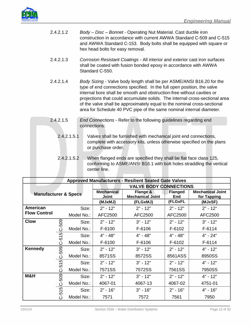
2.4.2.1.5 End Connections - Refer to the following guidelines regarding end connections:
2.4.2.1.5.1 Valves shall be furnished with mechanical joint end connections, complete with accessory kits, unless otherwise specified on the plans or purchase order.
2.4.2.1.5.2 When flanged ends are specified they shall be flat face class 125, conforming to ASME/ANSI B16.1 with bolt holes straddling the vertical center line.
Approved Manufacturers - Resilient Seated Gate Valves
Manufacturer & Specs VALVE BODY CONNECTIONS
Mechanical Joint
Flange & Mechanical Joint
Flanged End
Mechanical Joint for Tapping
(MJxMJ) (FLGxMJ) (FLGxFLG)
(MJxSF) American Flow Control
Size: 2" - 12" 2" - 12" 2" - 12" 2" - 12" Model No.: AFC2500 AFC2500 AFC2500 AFC2500
Clow
C-5
09
Size: 2" - 12" 3" - 12" 2" - 12" 3" - 12" Model No.: F-6100 F-6106 F-6102 F-6114
C-5
15
Size: 4" - 48" 4" - 48" 4" - 48" 4" - 24" Model No.: F-6100 F-6106 F-6102 F-6114 Kennedy
C-5
09
Size: 2" - 12" 3" - 12" 2" - 12" 4" - 12" Model No.: 8571SS 8572SS 8561ASS 8950SS
C-5
15
Size: 2" - 12" 3" - 12" 2" - 12" 4" - 12" Model No.: 7571SS 7572SS 7561SS 7950SS
M&H
C-5
09
Size: 2" - 12" 3" - 12" 2" - 12" 4" - 12" Model No.: 4067-01 4067-13 4067-02 4751-01
C-5
15
Size: 2" - 16" 3" - 16" 2" - 16" 4" - 16" Model No.: 7571 7572 7561 7950
10/1/14 Section 2556 – Water Distribution Systems Page 12 of 32
Engineering Manual
2.4.2.2 Resilient Seated Tapping (Gate) Valves - Resilient seated gate valves shall be designed and fabricated in accordance with the current AWWA Standard C-509 or C-515. The basic design of the gate valves shall have an iron body, elastomer encapsulated iron disc, bronze stem and operating nuts with non-rising stem design. Valves 16-inches and larger shall be equipped with right angle gears (bevel gearing) for horizontal installation. The valve working pressure for all sizes shall be a minimum of 250 psig with a test pressure of 500 psig.
2.4.2.2.1 Materials and Construction - Valves shall open counterclockwise with a 2-inch square iron operating nut secured to the valve stem by a corrosion resistant (Type 304 Stainless Steel) nut to threads on the valve stem. The valve stem shall be made of high tensile strength bronze and shall be of one piece construction sealed by O-Rings. The thrust collar shall be secured in place by a stuffing box or bonnet cover with a thrust washer located above the thrust collar. Valve construction shall be so that upper O-Rings can be replaced with the valve in service. The disc shall be iron encapsulated with an elastomer material bonded in accordance with ASTM D429 and shall be secured to the threaded stem by a bronze nut. The disk shall effect a seal that is bubble-tight at 250 psig.
2.4.2.2.2 Corrosion Resistant Coatings - All interior and exterior cast iron surfaces shall be coated with fusion bonded epoxy in accordance with AWWA Standard C-550.
2.4.2.2.3 Body Sizing - Valve body length shall be per ASME/ANSI B16.20 for tapping valves. Tapping valves shall conform to Specification AWWA C509 or C515, latest revision, covering gate valves except as modified for passage and clearance of tapping machine cutters. The opening through the valve shall be at least 1/4-inch larger than nominal valve diameter. Tapping valves shall allow full size shell cutters to be used.
2.4.2.2.4 End Connections - Valves shall be furnished with one end of the body with projecting face flange in accordance with specification MSS SP-60 for tapping valve/saddle connections to bolt to a standard tapping sleeve and the other end for mechanical joint.
2.4.2.3 Butterfly Valves - All butterfly valves shall be of the rubber-seated, tight-closing type. They shall meet or exceed AWWA Standard C504. All valves must use full AWWA C504 Class 150B valve shaft diameter, and full Class 150B underground service operator torque rating throughout entire travel, to provide capability for operation in emergency service.
2.4.2.3.1 Valve Construction - Valve body shall be high-strength ductile iron ASTM A126 with ASTM 276 18-8 Type 304 stainless steel body seat. Valve vane shall be high-strength cast iron ASTM A126, having rubber seat mechanically secured with an integral 18-8 stainless steel clamp ring and 18-8 stainless steel self-locked screws. Shaft shall be one piece ASTM
10/1/14 Section 2556 – Water Distribution Systems Page 13 of 32
Engineering Manual
276 Type 304 stainless steel. Bearings shall be sleeve-type, self-lubricated with O-Ring seals.
2.4.2.3.2 Operators - Operator shall be of the traveling-nut type, sealed, gasketed, and lubricated for underground service. It shall be capable of withstanding an overload input torque of 450 ft. lbs. at full-open or closed position without damage to the valve or valve operator. Operator shall have operating nut or post indicator as specified.
2.4.2.3.3 End Connection - End connections shall be mechanical joint, wafer-type with flange meeting ANSI B16.1 Class 125, and furnished as specified.
Approved Manufacturers Manufacturer Model Clow F-53XX* M & H 450, 1450, 4500 Others as approved by ECUA in writing.
* XX: See Manufacturer’s catalog to complete model numbers by size.
2.4.3 Valve Boxes - Valve boxes shall be provided for all direct buried valves. Use nominal (5 ¼) inch cast-iron, slip-type, or screw-type pipe shaft with cover and base casting. The box top shall be set at finished grade and encased with a concrete ring in unpaved areas. Each valve box shall be furnished with a drop-in cover marked “WATER”. See ECUA Standard Detail D-43.
2.4.4 Line Stops - Line stops are to be used where specified to temporarily stop water line water flow without depressurizing the entire line. The line stop parts and installation equipment are to be rated at a minimum of 150 psig working pressure unless otherwise specified.
2.4.4.1 Materials and Construction - Tapping saddles shall have 360º clamping on the main. All tapping saddles shall be fabricated of 304 Stainless Steel. All bolts and fasteners are to be 304 Stainless Steel, and the saddle shall be installed with Buna-N or neoprene rubber full facing gasket.
2.4.4.1.1 The stopping device attaching nozzle to be vendor’s standard with connecting threads or flange face, and the nozzle I.D. to be manufactured with a shelf to provide a position stop for the closure plug.
2.4.4.1.2 The closure plug is to be fabricated carbon steel, ductile iron, or malleable iron with at least one Buna-N or neoprene O-Ring seal on the outside diameter.
2.4.4.2 Corrosion-Resistant Coatings - Non-stainless steel permanently installed parts to have manufacturer’s standard red or black water base epoxy coating.
2.4.4.3 Connection - Tapping saddle shall be fabricated with dimensions to fit on concrete, steel, CA, PVC, CI, DI main as specified.
2.4.4.4 Installation - Temporary line stops shall only be installed by vendor personnel or contractor personnel trained and certified for stop by the vendor.
10/1/14 Section 2556 – Water Distribution Systems Page 14 of 32
Engineering Manual
2.4.5 Valve Insertions –
Approved Manufacturers (Main Sizes 4-inch – 42-inch) Manufacturer Contact Hydra-Stop, Inc. Phone: 800-538-7867 JCM 440 Phone: 800-527-8482 Romac Phone: Others as approved by ECUA in writing.
2.4.6 Location Aids – All new water main and service line installations shall include an approved method for locating lines from the ground surface after completion.
2.4.6.1 Tracer Wire - Tracer wire for water lines shall be minimum 12 gauge copper with blue PVC insulation for open trench installation. For trenchless installation, 8-gauge copper with blue PVC insulation shall be used. Tracer wire systems shall be electrically continuous covering all mains and services within the project. Wire-to-wire connectors shall be made with silicone-filled wire nuts. Wire-to-appurtenance attachments shall be made with lug-type terminals. Wire shall be secured to the top of each pipe joint with nylon ties or PVC tape placed on 10-foot intervals. Wire shall be secured to pipe with blue colored PVC Tape.
Approved Manufacturers (Tracer Wire Silicone-filled Wire Nut Connectors) Manufacturer Model Ideal Industries Twister® DB Plus King Technology, Inc. Failsafe™ Others as approved by ECUA in writing.
2.4.6.2 Pipeline Markers - When specified, markers shall be of a passive electronic type that reflects a signal back to an electronic hand-held transmitter/detector. Electronic components shall be enclosed in a blue waterproof polyethylene housing. Markers shall have a different response frequency for each service line type.
2.4.6.2.1 Markers shall be ScotchMark products manufactured by 3M Telecom Systems Group, Austin, Texas. Alternate manufacturers by ECUA in writing.
Application Usable Depth Dimension/Configuration Service Model Near Surface 2 Feet 3½”L X 5/8” ∅ Cylinder Water 1434 Medium Depth 4 Feet 4” ∅ Ball Water 1403 Deep 6 Feet 8” ∅ X 1” Thick Disc Water 1257
2.5 Hydrants and Flushing Equipment –
2.5.1 Fire Hydrants - Fire Hydrants shall be in compliance with the AWWA Standard C-502, with rated working pressure of 250 psig. The basic design of the fire hydrant shall be of the dry barrel type of breakaway traffic design. Use 304 stainless steel bolting below grade, and use fusion bond epoxy coating on mechanical joint inlet shoe, per AWWA C-550.
2.5.1.1 Hydrant Construction - Refer to the following guidelines regarding hydrant construction:
10/1/14 Section 2556 – Water Distribution Systems Page 15 of 32
Engineering Manual
2.5.1.1.1 The hydrant inlet connection shall be 6-inch mechanical joint type complete with Accessory kit.
2.5.1.1.2 The hydrant shall be designed with a safety feature incorporating a break-away flanged design. Split ring retainer-type breakaway design with pinch bolts is not acceptable. The hydrant design shall allow the upper barrel to be rotated 360 degrees in order to assure proper nozzle orientation.
2.5.1.1.3 The drain valve shall assure quick and complete drainage of the hydrant and the drain hole shall be brushed with bronze if passing through ductile iron. The drain valve sealing facing shall be made of Buna N, nylon or urethane. If the valve top plate comes in contact with the bronze seat ring to facilitate draining of the hydrant, the valve top plate shall be made of bronze.
2.5.1.2 Main Hydrant Valve - Refer to the following guidelines regarding main hydrant valve:
2.5.1.2.1 The main hydrant valve shall be compression type, opening counterclockwise against system pressure and closing clockwise with system pressure. The main valve connection opening shall not be less than 5¼-inches. The main valve shall have a resilient seat.
2.5.1.2.2 The hydrant shall be designed such that the operating threads on the stem are prevented from coming in contact with potable water and shall be enclosed in an operating chamber and sealed by O-Rings at the top and bottom of the chamber. The chamber shall be constructed for grease or oil lubrication with an installed grease fitting for maintenance.
2.5.1.2.3 The operating nut shall be 1½-inches in size and pentagon in shape and of one-piece construction.
2.5.1.2.4 The hydrant shall have one 4½-inch pumper nozzle, and two 2½-inch pumper nozzles having National Standard Hose coupling threads. The nozzles shall be field replaceable utilizing either a threaded or quarter-turn fitting with an O-Ring seal.
2.5.1.3 Operation and Maintenance Features - Refer to the following guidelines regarding operation and maintenance features:
2.5.1.3.1 The hydrant shall not incorporate parts requiring field adjustment for proper operation.
2.5.1.3.2 The hydrant shall be designed to permit the removal of all working parts from the hydrant through the barrel without disturbing the earth around the hydrant.
2.5.1.3.3 Removal of the working parts of the hydrant shall be accomplished by use of a seat removal wrench. Hydrants requiring other special tools to perform removal of interior parts will not be accepted.
10/1/14 Section 2556 – Water Distribution Systems Page 16 of 32
Engineering Manual
2.5.1.4 Materials - All operating parts including operating nut, hold-down nut, drain ring and seat ring shall be bronze. The valve seat ring shall thread into a bronze insert or drain ring to provide bronze-to-bronze seating. Breakaway stem coupling is to have bronze or stainless steel bolts or pins.
2.5.1.5 Markings - The fire hydrant shall have permanent markings identifying the manufacturer by name, initials or insignia, the size of the main valve opening, and the year of manufacture.
Approved Manufacturers Manufacturer Model No American Flow Control B62B M & H 129T Mueller A423 Others as approved by ECUA in writing.
2.5.2 Fire Hydrant Appurtenances –
2.5.2.1 Extensions Kits - Refer to the following guidelines regarding extension kits:
2.5.2.1.1 Where required, hydrants shall be installed using original manufacturer hydrant extension kits as necessary to position the hydrant breakaway flange above finish grade per ECUA Standard Detail D-50.
2.5.2.1.2 Stand extension shall be in standard lengths of 12, 24, 36, 48, and 60 inches.
2.5.2.2 Hydrant Connectors - Refer to the following guidelines regarding hydrant connectors:
2.5.2.2.1 Hydrant connector spools shall be ductile iron per AWWA C151 used for connection between the hydrant and lead valve, and shall incorporate joint restraints. One end of the connector spool shall have swivel flange. See ECUA Standard Detail D-50.
2.5.2.2.2 Standard hydrant connector sizes shall be as follows:
2.5.2.2.2.1 6-inch X 12-inch long
2.5.2.2.2.2 6-inch X 24-inch long
2.5.2.2.2.3 6-inch X 36-inch long
2.5.2.2.2.4 6-inch X 48-inch long
2.5.2.2.2.5 6-inch X 60-inch long
2.5.2.2.3 Hydrant Offset Connectors - When a height adjustment is required to avoid an obstruction between the hydrant shut-off valve and the hydrant, an offset fitting shall be used. Material to be ductile iron per ANSI/AWWA C153/A21.53. Sizes shall be as follows:
10/1/14 Section 2556 – Water Distribution Systems Page 17 of 32

Engineering Manual
2.5.2.2.3.1 6-inch X 18-inch long with 6-inch offset
2.5.2.2.3.2 6-inch X 30-inch long with 12-inch offset
2.5.2.2.3.3 6-inch X 41-inch long with 24-inch offset
Approved Manufacturers
Manufacturer Straight Hydrant Connector Offset Connector
Assured Flow Sales, Inc. N/A GRADELOK Clow N/A Others as approved by ECUA in writing.
2.5.3 Flushing Hydrants - Flushing hydrants shall be in general compliance with AWWA Standard C-502, with rated working pressure of 200 psig. A fully restrained gate valve shall be installed at each flushing hydrant per ECUA Standard Detail D-51.
2.5.3.1 Hydrant Construction - Flushing hydrants shall meet the requirements of Section 2.5.2.1, except the breakaway feature is not required.
2.5.3.2 Main Valve – Generally the same as Section 2.5.1.2, except main valve opening shall be not less than 2-1/8 inches and the flushing hydrant shall have one (1) 2½-inch nozzle having national standard hose coupling threads.
2.5.3.3 Operation and Maintenance Features - Unless otherwise specified, the hydrant bury length shall be 30-36 inches. The bury length is the distance measured to the nearest 1/2 foot, from the bottom of the connecting pipe to the ground line of the hydrant.
2.5.3.4 Materials - All operating parts including operating nut, hold-down nut, drain ring and seat ring shall be bronze. The valve seat ring shall thread into a bronze insert or drain ring to provide bronze-to-bronze seating.
2.5.3.5 Markings - Flushing hydrant markings shall meet the requirements of Section 2.5.1.5 for fire hydrants.
Approved Manufacturers Manufacturer Model M & H Style 33 Mueller A-411 Others as approved by ECUA in writing.
2.6 Water Service Lines –
2.6.1 Polyethylene (PE) - Tubing - Polyethylene service tubing for water supply shall conform to AWWA C901. However, only up to 2” will be allowed. PE tubing dimensions shall conform to ASTM D2737 with Copper Tubing OD base. Refer to Section 2.3.3 for service lines greater than 3 inches in diameter.
2.6.1.1 Materials - PE tubing material shall conform to ASTM D3350, Standard Code PE 3408.
10/1/14 Section 2556 – Water Distribution Systems Page 18 of 32
Engineering Manual
2.6.1.2 Pressure Rating - PE tubing shall be Pressure Class 200 psi with a minimum working pressure of 150 psig, and comply with ASTM D1598, D1599, D1693, D3350 and AWWA 901. Dimensions and acceptable standard sizes are as follows:
PE Tubing Dimensions (DR9) NOM OD WALL ID 1 1.125 .125 0.851 2 2.125 .236 1.625
2.6.1.3 Markings – Use the Following Markings:
2.6.1.3.1 Nominal Size
2.6.1.3.2 Standard PE Code: 3408
2.6.1.3.3 Tubing: DR-9
2.6.1.3.4 Pressure Class: PC200
2.6.1.3.5 Manufacturer’s Name or Trademark
2.6.1.3.6 Blue Markings and Stripes
2.6.1.3.7 Date Manufactured
Approved Manufacturers Manufacturer Model Endot Industries Endopoly, Endopure Chevron – Phillips Performance Pipe Driscoplex 5100 Series Ultra-Line Others as approved by ECUA in writing.
2.6.2 Copper Water Service Tubing - Copper water service tubing shall be Type K suitable for underground potable water services. Tracer wire is not required with copper tubing.
2.6.2.1 Material - Tubing is to be supplied in conformance with ASTM B88 for dimension and materials.
2.6.2.2 Pressure Rating - Test pressure shall be 200 PSI. Operating pressure shall be 150 PSI. Refer to the table below.
Copper Water Tubing Dimensions (ASTM B88)
Size (inches) Nominal OD Wall Thickness 1 1.125 .065 2 2.125 .083
2.6.2.3 Pipe Markings – Use the following markings:
2.6.2.3.1 Nominal Size
2.6.2.3.2 Type K
10/1/14 Section 2556 – Water Distribution Systems Page 19 of 32
Engineering Manual
2.6.2.3.3 ASTM B88
2.6.2.3.4 Manufacturer’s Name or Logo
2.6.2.3.5 NSF Seal
2.6.2.3.6 Date Manufactured
2.6.3 Pipe Sleeves for Long Water Services - Long water services shall be sleeved in PVC or PE pipe color coded blue or black with blue stripes. The sleeves shall be a minimum of 2” diameter with no fittings and shall extend one-foot either side of the paved surface. The sleeve shall be one continuous leak free piece which is open on each end. The long service shall be sized according to the table shown below.
Pipe Sleeve Sizing For Long Water Services Service Size (inches) Sleeve Size (inches)
1 2 2 4
2.7 Service Line Appurtenances –
2.7.1 Fittings and Valves - Fittings and valves shall be manufactured in accordance with AWWA C-800 and be listed and approved by NSF for underground use in potable water service.
2.7.1.1 Material - Refer to the following guidelines regarding material:
2.7.1.1.1 Fitting and valve bodies, plugs, and compression nuts shall be bronze, copper alloy no. C83600 and meet chemical and mechanical requirements of ASTM B62 or ASTM B584.
2.7.1.1.2 Component parts such as fasteners, seals, and packing may be of other materials selected for adequate endurance, corrosion resistance and strength in accordance with AWWA C-800.
2.7.1.2 Pressure - Fittings and valves shall be high pressure type for maximum allowable pressure of 150 PSIG, nominal operating pressure 100 PSIG.
2.7.1.3 Markings - Fittings and valves shall be marked as appropriate with the following information: manufacturer’s name or logo; pressure rating; direction of flow; and size.
2.7.1.4 Thread Specifications - Refer to the following table regarding thread specifications:
Thread Specifications Thread Type Standard Unified Inch ANSI/ASME B1.1
General Purpose Pipe ANSI/ASME B1.20.1 Dryseal ANSI/ASME B1.20.3
10/1/14 Section 2556 – Water Distribution Systems Page 20 of 32
Engineering Manual
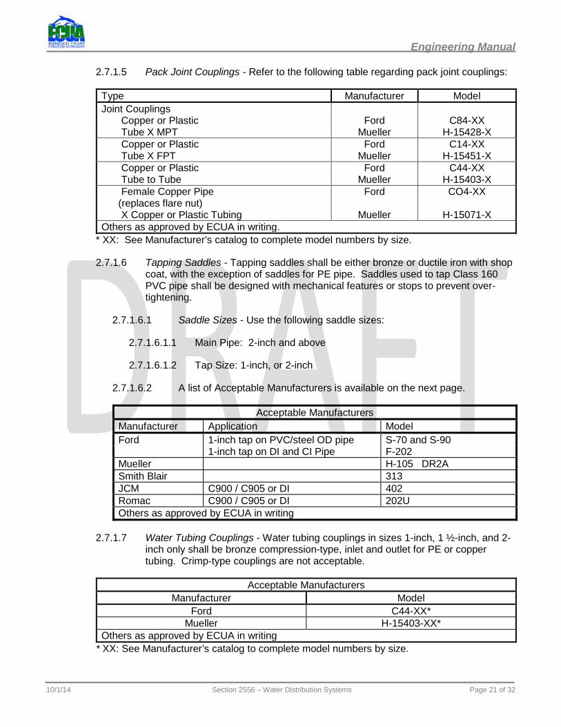
2.7.1.5 Pack Joint Couplings - Refer to the following table regarding pack joint couplings:
Type Manufacturer Model Joint Couplings Copper or Plastic Tube X MPT
Ford
Mueller
C84-XX
H-15428-X Copper or Plastic Tube X FPT
Ford Mueller
C14-XX H-15451-X
Copper or Plastic Tube to Tube
Ford Mueller
C44-XX H-15403-X
Female Copper Pipe (replaces flare nut) X Copper or Plastic Tubing
Ford
Mueller
CO4-XX
H-15071-X Others as approved by ECUA in writing.
* XX: See Manufacturer’s catalog to complete model numbers by size.
2.7.1.6 Tapping Saddles - Tapping saddles shall be either bronze or ductile iron with shop coat, with the exception of saddles for PE pipe. Saddles used to tap Class 160 PVC pipe shall be designed with mechanical features or stops to prevent over-tightening.
2.7.1.6.1 Saddle Sizes - Use the following saddle sizes:
2.7.1.6.1.1 Main Pipe: 2-inch and above
2.7.1.6.1.2 Tap Size: 1-inch, or 2-inch
2.7.1.6.2 A list of Acceptable Manufacturers is available on the next page.
Acceptable Manufacturers Manufacturer Application Model Ford 1-inch tap on PVC/steel OD pipe S-70 and S-90
1-inch tap on DI and CI Pipe F-202 Mueller H-105 DR2A Smith Blair 313 JCM C900 / C905 or DI 402 Romac C900 / C905 or DI 202U Others as approved by ECUA in writing
2.7.1.7 Water Tubing Couplings - Water tubing couplings in sizes 1-inch, 1 ½-inch, and 2-inch only shall be bronze compression-type, inlet and outlet for PE or copper tubing. Crimp-type couplings are not acceptable.
Acceptable Manufacturers Manufacturer Model
Ford C44-XX* Mueller H-15403-XX*
Others as approved by ECUA in writing * XX: See Manufacturer’s catalog to complete model numbers by size.
10/1/14 Section 2556 – Water Distribution Systems Page 21 of 32
Engineering Manual
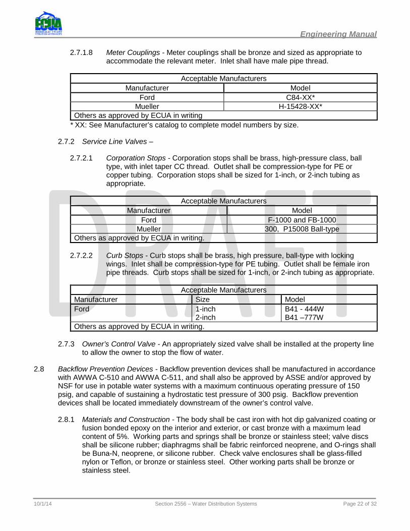
2.7.1.8 Meter Couplings - Meter couplings shall be bronze and sized as appropriate to accommodate the relevant meter. Inlet shall have male pipe thread.
Acceptable Manufacturers Manufacturer Model
Ford C84-XX* Mueller H-15428-XX*
Others as approved by ECUA in writing * XX: See Manufacturer’s catalog to complete model numbers by size.
2.7.2 Service Line Valves –
2.7.2.1 Corporation Stops - Corporation stops shall be brass, high-pressure class, ball type, with inlet taper CC thread. Outlet shall be compression-type for PE or copper tubing. Corporation stops shall be sized for 1-inch, or 2-inch tubing as appropriate.
Acceptable Manufacturers Manufacturer Model
Ford F-1000 and FB-1000 Mueller 300, P15008 Ball-type
Others as approved by ECUA in writing.
2.7.2.2 Curb Stops - Curb stops shall be brass, high pressure, ball-type with locking wings. Inlet shall be compression-type for PE tubing. Outlet shall be female iron pipe threads. Curb stops shall be sized for 1-inch, or 2-inch tubing as appropriate.
Acceptable Manufacturers Manufacturer Size Model Ford 1-inch
2-inch B41 - 444W B41 –777W
Others as approved by ECUA in writing.
2.7.3 Owner’s Control Valve - An appropriately sized valve shall be installed at the property line to allow the owner to stop the flow of water.
2.8 Backflow Prevention Devices - Backflow prevention devices shall be manufactured in accordance with AWWA C-510 and AWWA C-511, and shall also be approved by ASSE and/or approved by NSF for use in potable water systems with a maximum continuous operating pressure of 150 psig, and capable of sustaining a hydrostatic test pressure of 300 psig. Backflow prevention devices shall be located immediately downstream of the owner’s control valve.
2.8.1 Materials and Construction - The body shall be cast iron with hot dip galvanized coating or fusion bonded epoxy on the interior and exterior, or cast bronze with a maximum lead content of 5%. Working parts and springs shall be bronze or stainless steel; valve discs shall be silicone rubber; diaphragms shall be fabric reinforced neoprene, and O-rings shall be Buna-N, neoprene, or silicone rubber. Check valve enclosures shall be glass-filled nylon or Teflon, or bronze or stainless steel. Other working parts shall be bronze or stainless steel.
10/1/14 Section 2556 – Water Distribution Systems Page 22 of 32

Engineering Manual
2.8.2 Double-Check Valve - Double-check backflow preventers shall have two independent check valve assemblies. The body may consist of one or more castings, and shall be equipped with ports and valves as necessary to allow testing in place. If required by ECUA, a detector must be provided
2.8.3 Reduced Pressure Principle Device - Reduced pressure principle backflow preventers shall have two independent check valves with an intermediate relief valve incorporating a pressure diaphragm valve assembly that maintains a minimum 2 psig differential pressure across the assembly.
2.8.4 End Connections - Devices shall be manufactured with standard female pipe thread, size 3/4-inch, 1-inch, 1-1/2-inch, or standard ASME/ANSI B16.20 Class 125 flanged, sizes 2-inch and greater.
2.8.5 Appurtenances - All back flow devices shall be provided and installed as a complete assembly with all necessary fittings to enable testing in place. Tapped test ports shall be fitted with test petcocks in each body cavity. Inlet and outlet gate or ball valve shall be of the same line size as that of the body.
2.8.6 Acceptable Manufacturers - A list of Acceptable Manufacturers are listed in the following table:
Acceptable Manufacturers Type Device
Manufacturer Double Check Double Check Detector Reduced Pressure Ames 2000 DCA OSY
2000 DCA NRS 2000 DCA OSY Epoxy 2000 DCA NRS Epoxy
3000 DCDA OSY 3000 DCDA NRS 3000 DCDA OSY Epoxy 3000 DCDA NRS Epoxy
4000 RP OSY 4000 RP NRS
Febco 850 NRS 850 OSY
860 NRS 860 OSY
Watts 709 OS&Y/BV 709 DDC 909 909 DDC (Detector)
Hersey 3/4” - 2” FDC 3” - 10” No. 2
3” - 10” DDC II 3/4” - 2” FRP II 2½” - 10” 6CM
Others as approved by ECUA in writing.
2.9 Meter Box Assemblies - Meter box assemblies for 5/8-inch meters shall be cast iron open bottom per ASTM A-48 with cast iron lid with ECUA imprint. The box assembly shall include a ball valve with locking nuts, pack joint coupling for copper or PE tubing with expansion connection and gaskets as needed. Meter box and cover for meters 2-inch and larger shall be constructed in accordance with ECUA Standard Details D-44 and D-45.
Acceptable Manufacturers Manufacturer Model Meter Size Ford G148-133 (Modified) w/ 1” pack joint for copper or PE Tubing 5/8” Others as approved by ECUA in writing.
10/1/14 Section 2556 – Water Distribution Systems Page 23 of 32
Engineering Manual
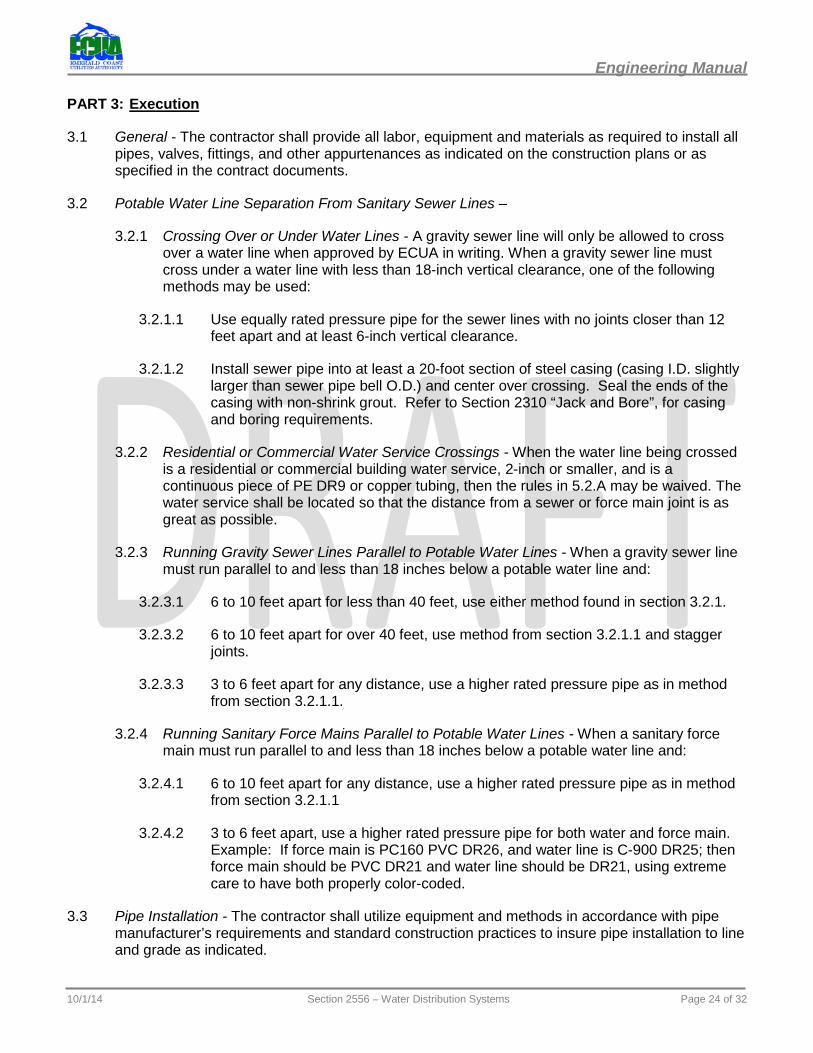
PART 3: Execution
3.1 General - The contractor shall provide all labor, equipment and materials as required to install all pipes, valves, fittings, and other appurtenances as indicated on the construction plans or as specified in the contract documents.
3.2 Potable Water Line Separation From Sanitary Sewer Lines –
3.2.1 Crossing Over or Under Water Lines - A gravity sewer line will only be allowed to cross over a water line when approved by ECUA in writing. When a gravity sewer line must cross under a water line with less than 18-inch vertical clearance, one of the following methods may be used:
3.2.1.1 Use equally rated pressure pipe for the sewer lines with no joints closer than 12 feet apart and at least 6-inch vertical clearance.
3.2.1.2 Install sewer pipe into at least a 20-foot section of steel casing (casing I.D. slightly larger than sewer pipe bell O.D.) and center over crossing. Seal the ends of the casing with non-shrink grout. Refer to Section 2310 “Jack and Bore”, for casing and boring requirements.
3.2.2 Residential or Commercial Water Service Crossings - When the water line being crossed is a residential or commercial building water service, 2-inch or smaller, and is a continuous piece of PE DR9 or copper tubing, then the rules in 5.2.A may be waived. The water service shall be located so that the distance from a sewer or force main joint is as great as possible.
3.2.3 Running Gravity Sewer Lines Parallel to Potable Water Lines - When a gravity sewer line must run parallel to and less than 18 inches below a potable water line and:
3.2.3.1 6 to 10 feet apart for less than 40 feet, use either method found in section 3.2.1.
3.2.3.2 6 to 10 feet apart for over 40 feet, use method from section 3.2.1.1 and stagger joints.
3.2.3.3 3 to 6 feet apart for any distance, use a higher rated pressure pipe as in method from section 3.2.1.1.
3.2.4 Running Sanitary Force Mains Parallel to Potable Water Lines - When a sanitary force main must run parallel to and less than 18 inches below a potable water line and:
3.2.4.1 6 to 10 feet apart for any distance, use a higher rated pressure pipe as in method from section 3.2.1.1
3.2.4.2 3 to 6 feet apart, use a higher rated pressure pipe for both water and force main. Example: If force main is PC160 PVC DR26, and water line is C-900 DR25; then force main should be PVC DR21 and water line should be DR21, using extreme care to have both properly color-coded.
3.3 Pipe Installation - The contractor shall utilize equipment and methods in accordance with pipe manufacturer’s requirements and standard construction practices to insure pipe installation to line and grade as indicated.
10/1/14 Section 2556 – Water Distribution Systems Page 24 of 32
Engineering Manual
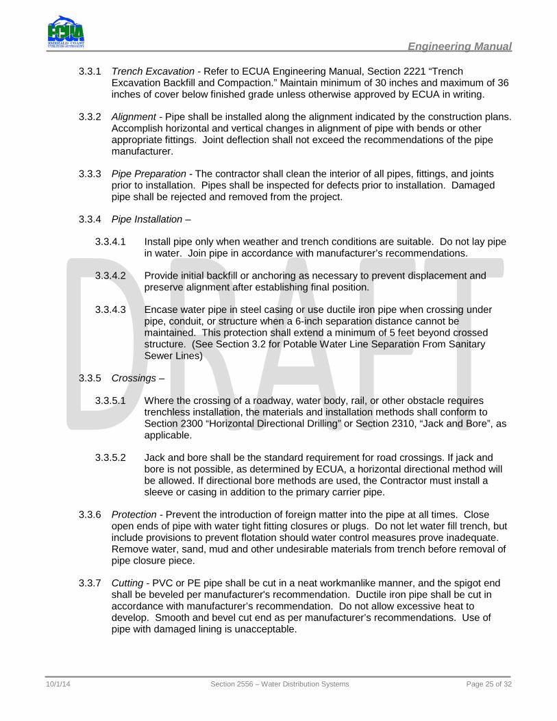
3.3.1 Trench Excavation - Refer to ECUA Engineering Manual, Section 2221 “Trench Excavation Backfill and Compaction.” Maintain minimum of 30 inches and maximum of 36 inches of cover below finished grade unless otherwise approved by ECUA in writing.
3.3.2 Alignment - Pipe shall be installed along the alignment indicated by the construction plans. Accomplish horizontal and vertical changes in alignment of pipe with bends or other appropriate fittings. Joint deflection shall not exceed the recommendations of the pipe manufacturer.
3.3.3 Pipe Preparation - The contractor shall clean the interior of all pipes, fittings, and joints prior to installation. Pipes shall be inspected for defects prior to installation. Damaged pipe shall be rejected and removed from the project.
3.3.4 Pipe Installation –
3.3.4.1 Install pipe only when weather and trench conditions are suitable. Do not lay pipe in water. Join pipe in accordance with manufacturer’s recommendations.
3.3.4.2 Provide initial backfill or anchoring as necessary to prevent displacement and preserve alignment after establishing final position.
3.3.4.3 Encase water pipe in steel casing or use ductile iron pipe when crossing under pipe, conduit, or structure when a 6-inch separation distance cannot be maintained. This protection shall extend a minimum of 5 feet beyond crossed structure. (See Section 3.2 for Potable Water Line Separation From Sanitary Sewer Lines)
3.3.5 Crossings –
3.3.5.1 Where the crossing of a roadway, water body, rail, or other obstacle requires trenchless installation, the materials and installation methods shall conform to Section 2300 “Horizontal Directional Drilling” or Section 2310, “Jack and Bore”, as applicable.
3.3.5.2 Jack and bore shall be the standard requirement for road crossings. If jack and bore is not possible, as determined by ECUA, a horizontal directional method will be allowed. If directional bore methods are used, the Contractor must install a sleeve or casing in addition to the primary carrier pipe.
3.3.6 Protection - Prevent the introduction of foreign matter into the pipe at all times. Close open ends of pipe with water tight fitting closures or plugs. Do not let water fill trench, but include provisions to prevent flotation should water control measures prove inadequate. Remove water, sand, mud and other undesirable materials from trench before removal of pipe closure piece.
3.3.7 Cutting - PVC or PE pipe shall be cut in a neat workmanlike manner, and the spigot end shall be beveled per manufacturer's recommendation. Ductile iron pipe shall be cut in accordance with manufacturer’s recommendation. Do not allow excessive heat to develop. Smooth and bevel cut end as per manufacturer’s recommendations. Use of pipe with damaged lining is unacceptable.
10/1/14 Section 2556 – Water Distribution Systems Page 25 of 32
Engineering Manual
3.3.8 Service Lines - Service lines shall be constructed where shown on plans and in accordance with ECUA Standard Detail D-40.
3.3.8.1 Long Service Lines - Unless noted on plans, HDPE pipe and tubing shall be installed at the shallowest depth that can safely and reasonably be achieved (but no less than 36” minimum). Depth shall take into account all utility conflicts, bend radius of the pipe, and bend radius of the drill stem. Where utilities cross under DOT, county and/or city roads, depth of cover shall comply with applicable permits and shall be adequate to provide reasonable measures to avoid damage to the road surface and/or road base.
3.3.9 Closure Pieces - Closure pieces shall only be used where called for on plans, or with written permission of the ECUA. Closure may be accomplished with sleeve coupling as long as its length is such that gaskets are not less than 3 inches from pipe ends.
3.3.10 Restraints and Thrust Blocking - Mechanical joint restraints shall be furnished and installed for all water line fittings and appurtenances. Reference ECUA Standard Detail D-62. Restraints and thrust blocks are required for 11.25º, 22.5º, 45º and 90º bends, tapping sleeves, tees, dead-ends, behind fire hydrants, and flushing hydrants. Reference ECUA Standard Details D-52 and D-62.
3.4 Appurtenance Installation –
3.4.1 Valves - Valves shall be installed with operating stems vertical when installation is direct burial. Valves shall be installed on a suitable bearing surface so as to prevent vertical displacement.
3.4.2 Valve Boxes - Valve boxes shall be centered on the valve. The earth shall be compacted around each valve box to a distance of 4 feet on all sides of box, or to undisturbed trench face if less than 4 feet. An 18-inch diameter by 4-inch thick collar shall be constructed and sloped to direct water away from the valve box. In lieu of the constructed collar, a 24-inch by 4-inch thick pre-cast, sloped, concrete collar may be used.
3.4.3 Tracer Wire - Tracer wire shall be installed on all new water mains and on all new water service lines. The tracer wire shall be placed directly above the pipe and electrically continuous throughout the project. Tracer wire shall be secured to the pipe with PVC tape the same color as the wire insulation, at a maximum of 10-feet on center between tapings. The tracer wire shall be brought to the ground surface at each valve location in accordance with ECUA Standard Detail D-43. Splices and/or connections in the tracer wire shall be installed with silicone-filled wire nuts designed for direct burial.
3.5 Fire Hydrant Flushing Equipment Installation –
3.5.1 Hydrants - Hydrants shall be installed in accordance with ECUA Standard Detail D-50.
3.5.2 Flush Stands and Valves - Flush stands shall be installed as shown on ECUA Standard Detail D-51, depending on line size.
3.6 Service Line Installation –
3.6.1 General - The contractor shall install individual services with tracer wire from the new main to a convenient point on the right-of-way or property line for each house, building or
10/1/14 Section 2556 – Water Distribution Systems Page 26 of 32
Engineering Manual
unit that is currently served through an ECUA meter. New services for undeveloped lots shall be located 1 foot from the common property line.
3.6.1.1 This section will deal with service line tubing 1-inch and 2-inches in diameter, to serve 5/8-inch, 1-inch, 1 ½-inch, and 2-inch meters. The installation of service lines for 3-inch meters and larger shall be in accordance with the requirements for water main installation, (See Section 3.3).
3.6.2 Service Line Connections - Service lines shall be installed in accordance with ECUA Standard Detail D-40. Tubing shall be installed in one continuous length from corporation stop to curb stop with no intermediate fittings. Service lines damaged after initial installation but before acceptance may be repaired by means of a single splice, except that no repair fittings will be permitted under any paving. The tap location shall be at least 10 feet from any sanitary sewer joint with less than 18 inches vertical clearance. Potable water taps shall be made with a tapping machine designed for the pipe material being tapped. Other types of tapping machines may be used upon prior approval by the ECUA Inspector or Engineer.
3.7 Taps on Pressurized Lines - Taps for service lines of 2-inch and smaller PE tubing shall be made using a tapping saddle. The contractor shall perform taps on pressurized lines for the installation of pipes other than service lines of 2-inch and smaller PE tubing in accordance with these requirements:
3.7.1 Materials - All materials used for taps on pressurized lines shall meet the requirements of these specifications. Tapping sleeves shall be properly sized for the pipe being tapped. (See Section 2.4.1.8) Resilient seated tapping valves shall be furnished with special end connections. (See Section 2.4.2.2) All other material used to accomplish the tap shall meet the standards set forth by the AWWA for potable water construction.
3.7.2 Procedure - The contractor shall notify the ECUA Inspector three working days in advance of work. The contractor shall in the presence of an ECUA inspector:
3.7.2.1 Expose the existing pipe at the location shown on the plans, and clean the section of the pipe to receive the tapping sleeve.
3.7.2.2 Check the tapping sleeve and valve for defects and make sure the gate fully retracts in the valve to allow the shell cutter free passage.
3.7.2.3 Assemble the tapping sleeve on the pipe, then install the tapping valve.
3.7.2.4 Hydrostatically pressure test the tapping sleeve and valve after it has been assembled on the water main using the test plug on the sleeve. The test shall be 150 psi minimum. The duration of the test shall be 15 minutes.
3.7.2.5 Pour a thrust block behind the tapping sleeve sufficient to withstand the pressure of the new line. Also, provide a concrete pad or suitable bearing surface sufficient to support the weight of the sleeve, valve, and tapping machine. Refer to Section 3.3 and ECUA Standard Detail D-52. Concrete shall be in place a minimum of 24 hours prior to testing the main installation.
3.7.2.6 Assemble an approved tapping machine and proceed to make the necessary cut in accordance with the recommendation of the tapping machine manufacturer. Approved tapping machines shall be:
10/1/14 Section 2556 – Water Distribution Systems Page 27 of 32

Engineering Manual
3.7.2.6.1 In good working condition.
3.7.2.6.2 Designed for and have a cutting bit for the pipe material to be cut.
3.7.2.6.3 Equipped with a depth of cut gauge.
3.7.2.6.4 Designed to capture the coupon.
3.7.2.6.5 Equipped with the manufacturer’s recommended diameter shell cutter for the tap to be made.
3.7.2.6.6 Tapping machine power head to be hydraulic or pneumatic drive; use of electric motor drives expressly prohibited.
3.7.2.6.7 Tapping machine shall be disinfected prior to each use for potable water taps.
3.7.2.7 The following tapping chart may be used for field reference only:
Nominal Main Size
Tapping Valve ID AWWA Standard Tapping Machine Shell Cutter OD
2-inch 2 1/8-inch 1½ -inch 3-inch 3 1/8-inch 2½-inch 4-inch 4 1/4-inch 3½ -inch 6-inch 6 1/4-inch 5½ -inch 8-inch 8 1/4-inch 7½ -inch 10-inch 10 1/4-inch 9½ -inch 12-inch 12 1/4-inch 11½ -inch 14-inch 14 1/4-inch Per Manufacturer’s Recommendation. 16-inch 16 1/4-inch Contractor shall submit shop drawings for
valves and tapping machine for approval, prior to use. Per Manufacturer’s Recommendation.
18-inch 18 1/4-inch 20-inch 20 1/4-inch 24-inch 24 1/4-inch
3.7.2.8 Tap coupon shall be given to the ECUA Inspector. If the coupon is lost in the main, contractor shall, at his expense, dismantle main to retrieve the coupon. Main will be reassembled, pressure tested and bacteriological tests retaken as required at contractor’s expense.
PART 4: Acceptance Requirements
4.1 Inspection - Upon completion of the installation, the system shall be inspected to ascertain that valves, fittings, fire hydrants, flush hydrants, etc. are located in conformance with the plans, and confirm that all ‘as-built’ measurements have been accurately taken. The ECUA Inspector shall observe all appropriate activities related to properly placing the line in service including flushing, pressure and leakage testing, disinfection, and bacteriological sampling. Final connections and testing of fire hydrants shall be accomplished after final clearance of lines. Tracer wire shall be tested for continuity by the contractor with the ECUA Inspector present. The contractor, with the ECUA Inspector, shall make sure all main valves and hydrant valves are open.
10/1/14 Section 2556 – Water Distribution Systems Page 28 of 32
Engineering Manual
4.2 New Water Main Cleaning - All newly installed water lines shall be flushed with potable water to remove any sediment, solids and/or foreign matter prior to testing. ECUA will make water available to the contractor. Flushing shall be conducted at a sufficient velocity to clear the pipe. Discharge of flushing water must be through a 2-inch diameter pipe (or larger) and must be controlled so as not to cause any property damage. Chlorinated water must be disposed of in an acceptable manner. Flush water source connection shall incorporate backflow preventer when required by the ECUA Inspector or Engineer.
4.2.1 Larger Pipe - 12” or larger diameter pipe shall be flushed and swabbed a minimum of 3 passes until line is clear. To facilitate this process, pigging launch stations and receiving pits shall be installed and incorporated into system.
4.3 Pressure/Leakage Test -
4.3.1 General - All newly installed water lines and appurtenances shall be pressure/leak tested to assure the strength of materials and quality of workmanship of the installation. Testing shall be conducted in accordance with ECUA Standard Detail D-41 and the requirements of AWWA Manual 23 for PVC and other flexible pipe or AWWA C600 for Ductile Iron Pipe. Leakage testing may be conducted concurrently with the pressure test.
4.3.2 Procedure –
4.3.2.1 Contractor shall notify the ECUA Inspector three ECUA working days prior to a scheduled test. Tests are to be conducted in segments not to exceed three thousand (3,000) feet of pipe. Water in the new line shall be pumped up to a pressure of 150 psi minimum. This pressure shall be maintained for a minimum of one (1) hour by pumping a quantifiable amount of water into the line and record the amount of water added during the test period. This represents the leakage.
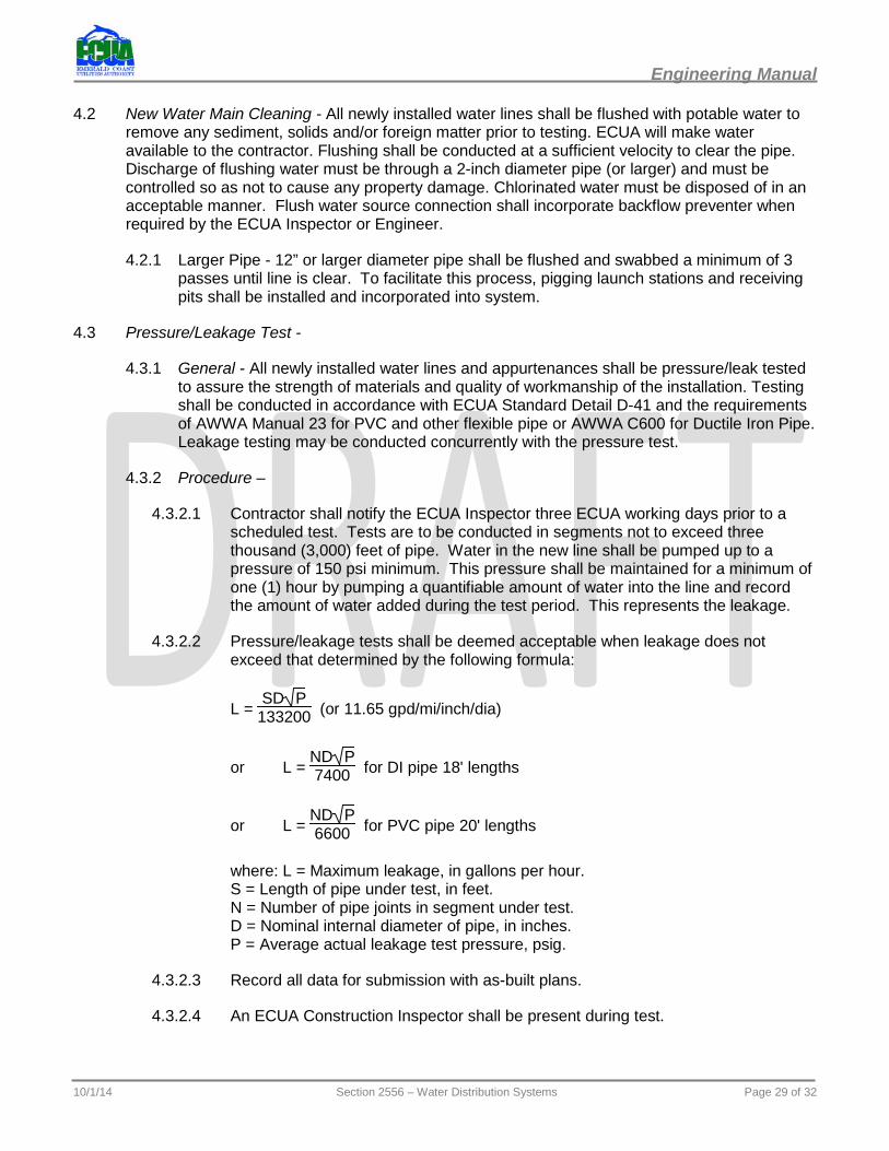
4.3.2.2 Pressure/leakage tests shall be deemed acceptable when leakage does not exceed that determined by the following formula:
L = EA
SD PE133200 E
A (or 11.65 gpd/mi/inch/dia)
or L = AAEA
ND PE7400E
A for DI pipe 18' lengths
or L = AAEA
ND PE6600E
A for PVC pipe 20' lengths
where: L = Maximum leakage, in gallons per hour. S = Length of pipe under test, in feet. N = Number of pipe joints in segment under test. D = Nominal internal diameter of pipe, in inches. P = Average actual leakage test pressure, psig.
4.3.2.3 Record all data for submission with as-built plans.
4.3.2.4 An ECUA Construction Inspector shall be present during test.
10/1/14 Section 2556 – Water Distribution Systems Page 29 of 32
Engineering Manual
4.3.2.5 Refit and replace all pipe not meeting the leakage requirements. Repair clamps are not permitted.
4.3.2.6 Repair all visible leaks regardless of the amount of leakage.
4.3.2.7 When a satisfactory pressure/leakage test has been completed, reduce the pressure at or below normal line pressure, and continue on with line disinfection.
4.4 Disinfection -
4.4.1 General - The contractor shall provide all equipment, materials and testing apparatus required to perform disinfection in accordance with AWWA C651, ECUA Standard Detail D-41.
4.4.2 Procedure -
4.4.2.1 Prior to beginning disinfection, the contractor shall submit information to the Engineer for approval of proposed materials and methods. ECUA will determine the number and location of all sampling points. Temporary sampling taps may be required consisting of a corporation cock with copper tube.
4.4.2.2 Method of disinfection shall be the continuous feed method as described in AWWA-C651. Add chlorine to attain an initial concentration of 25 mg/l chlorine with 10 mg/l remaining after 24 hours.
4.4.2.3 Initial concentration is to be obtained by mixing proper amount of HTH granules (65% Cl) into auxiliary tank, then pump/meter into regulated flow into or through the pipe section.
4.4.2.4 Check the chlorine concentration at all sampling points after the line has been filled and air expelled. Check residual chlorine concentration at the end of 24 hours to confirm that 10 ppm (minimum) is present.
4.4.2.5 Alternate methods of disinfection such as “tablet” and “slug” methods as described in AWWA C651 will not be allowed.
4.4.3 Water Supply for Cleaning, Flushing and Disinfection - ECUA shall supply water for testing from the nearest available source. Flush main until chlorine concentration is 2 mg/l or less prior to taking bacteriological samples. Contractor shall provide a backflow preventer device as required by the ECUA Inspector or Engineer.
4.4.3.1 Check concentration at all sample point locations.
4.4.3.2 Disposal of chlorinated water shall be the contractor’s responsibility and shall be done without damage to public or private property. Chlorinated water disposal shall meet all State, Federal and local regulations.
4.4.4 Collection of Samples - Contact ECUA for collection of samples. Two (2) satisfactory bacterial sample sets taken 24 hours apart must meet State requirements before placing the main into service.
4.4.5 Repeat Testing - Repeat flushing and disinfection procedure should initial disinfection fail to yield acceptable bacteriological results at no additional cost to the Owner.
10/1/14 Section 2556 – Water Distribution Systems Page 30 of 32
Engineering Manual
4.5 Other Connections - After new system piping has been satisfactorily tested and cleared for use, make any approved additional connections to the pre-existing distribution system. Exercise care in making connection and disinfect as needed. When total system is approved for use, an ECUA Inspector shall verify that the contractor has opened all interior valves as required. Valves connecting new installations to ECUA’s existing distribution system shall then be opened by an ECUA Inspector.
4.6 Testing Fire Hydrants - All newly-installed fire hydrants shall be flow tested by ECUA prior to final acceptance in accordance with established procedures. (Refer to AWWA-M17 and AWWA C502.) Static Leak Test of hydrant shall be done in conjunction with Section 4.3 with hydrant valve open. Hydrant flow tests not meeting the minimum requirements of ECUA’s Design Standards shall be immediately reported to the Engineer-of-Record. The system shall not be placed into service until the system meets the minimum requirements.
PART 5: UMeasurement and payment
5.1 General - Measurements shall be made to the nearest tenth of units and rounded to the nearest whole unit when totaled. Payments shall be for providing all labor, tools, equipment and materials as needed for: 1) furnishing, handling, and installing the required materials, fittings or fixtures; 2) excavation, backfill and compaction, including shoring, bracing and dewatering as required; 3) temporary removal and replacement of existing obstacles, including minor relocation and repair of other utilities; and 4) all required testing, disinfection and flushing. Payment for water main installations shall include the installation of tracer wire. All items stated are to be included in the unit price of pipe unless individually identified in the bid form.
5.2 Water Mains - Water mains shall be measured in lineal feet by the specified pipe size along the pipe centerline with no deduction for fittings. Payment shall be based on the contract unit price per lineal foot.
5.3 Appurtenances - Water main appurtenances include fittings and valves as outlined in Section 2.4 of the specifications. Incidental appurtenances such as joint restraints, couplings, tracer wire, etc. are not considered separate pay items and their cost should be included in the unit price of the installed pipe.
5.3.1 Fittings - Water main fittings including bends, reducers, tees, wyes, tapping sleeves, expansion joints, pipe restraints, pipe hangers/supports, and cut in sleeves shall be measured and paid for on a unit (per each) basis. Fittings shall be listed by size and type.
5.3.2 Valves - Water main valves inclusive of any required valve boxes or other appropriate appurtenances shall be measured and paid for on a unit (per each) basis. Valves shall be listed by size and type.
5.3.3 Line Stops - Line stops shall be measured and paid for on a unit (per each) basis.
5.4 Hydrants And Flushing Equipment - Hydrants and flushing equipment shall be measured and paid for on a unit (per each) basis to include a complete installed assembly.
5.4.1 Fire Hydrants - Fire hydrant assemblies shall include the installed water main tee or tapping sleeve, lead valve and box, connectors (up to 10 feet of lateral distance), gravel pack, extensions, offset connectors and hydrant.
10/1/14 Section 2556 – Water Distribution Systems Page 31 of 32
Engineering Manual
5.5 Water Service Lines -
5.5.1 Service Lines (up to 2-inch diameter) - Water service lines shall be measured and paid for on a unit (per each) basis. Each service line installation shall include the main tap, corporation stop, service tubing, and curb stop. Service lines shall be listed by tubing size and nominal length. Nominal length shall typically be categorized as “short” (for services on the same side of the street as the water main), and “long” (for services on the opposite side of the street from the water main).
5.5.2 Large Service Lines (3-inch diameter and larger) - Large service lines, including fire lines, shall be measured and paid for in accordance with the requirements for water mains (see 5.2 and 5.3 above).
5.6 Taps On Pressurized Lines - Taps on pressurized lines shall be measured and paid for on a unit price (per each) basis to include tapping sleeve, tapping valve, and valve box complete, in-place. Taps shall be listed by main and branch diameters.
10/1/14 Section 2556 – Water Distribution Systems Page 32 of 32