Embed Size (px)
Citation preview
KNOXVILLE UTILITIES BOARD
STANDARDS AND SPECIFICATIONS
Released XX.XX.XX Electric Metering 16210-1
SECTION 16210
ELECTRIC METERING
PART 1. GENERAL
1.1 Around 1990 KUB began using an “electronic meter” which is basically a digital device measuring
analog values. It contains built-in precision current and potential transformers to produce values
suitable for electronic circuits. This is a known analog ratio of actual load current and voltage.
These analog signals are sampled many times per hour and fed into Analog-to-Digital Converters.
This results in a very accurate digital form of the current and voltage. As the current and voltage
are sampled, Real Power is calculated in a Digital Signal Processor (DSP) by multiplying the
Current times the Voltage times the Power Factor. The Power Factor (PF) is the Cosine of the
measured angle displacement between the voltage and the current. Newer electronic meters can
measure and record harmonics, voltage imbalance, current imbalance, and other quantities. Some
customers opt for an electronic meter with a “telephone modem” (KYZ) which supplies several
pulse signals that enable customers to control power usage and track “demands”. KUB also installs
modems for automatic/remote meter reading. Customer should have phone connection within
twelve inches of the meter. This will advance the MV-90 Remote Reading Module. This phone
connection does not need to be a dedicated line, but can be an extension. The “demand” of a
service is the amount of power delivered averaged over a specified interval of time (typically 30
minutes). For any commercial/industrial service with an estimated demand of over 50 kW
(kilowatts), KUB will install an electronic meter with demand register.
Electric bills can contain as many as 3 metered quantities:
(1) Kilowatt-Hours (kWh) (The Power Consumed each month)
(2) Kilowatts Demand (The Max. Consumption in a 30-minute period each month)
(3) Kilowatts (kW) Demand with Power Factor (PF) Penalty. Due to customer inductance &
capacitance in Alternating-Current (AC) circuits, the current & voltage get out of phase
with each other (by an angle “A”). A penalty is imposed for operating at Power Factors
below 0.85 (voltage lagging the current). In specific situations there is also a Power Factor
penalty for operating above 1.00 (voltage leading the current).
(a) kW = Real Power required to do work = current X voltage X PF (cos A)
(b) kVA = Apparent Power = current X voltage
(c) RkVA = Power that performs no work = current X voltage X sin A
(d) PF = Ratio of Real Power to Apparent Power = kW divided by kVA
1.2 ELECTRIC METER CODES:
All KUB electric meters have unique numbers. This unique number includes a 5 digit prefix, and a
5 digit suffix. The prefix describes the meter, while the suffix indicates the particular meter number
within a group.
For example: J2E08 – 12345
KNOXVILLE UTILITIES BOARD
STANDARDS AND SPECIFICATIONS
Released XX.XX.XX Electric Metering 16210-2
J2E08 J2E08 J2E08 J2E08 (J2E8)
Meter Configuration or Use Service Voltage Service Type & Phases Meter A or CT
A – Bottom-connected 1 – 120 Volts A – 2-Wire, 1-PH 2 – 5 Amps
B – Socket-type 2 – 120/240 Volts C – 3-Wire, 3-PH 4 – 10 Amps
C – Legacy, not used (Begin PT's) E – 3-Wire, 1-PH 5 – 15 Amps
D – Socket-type 3 – 480Y/277 Volts F – 4-Wire, 3-PH Wye 6 – 20 Amps
E – Bottom-connected 4 – 480 Volts G – 4-Wire, 3-PH Delta 7 – 25 Amps
F – Socket-type 6 – 4000Y/2300 H – 3-Wire, 2-PH Network 8 – 30Amps
G – Bottom-connected 7 – 69000Y/40000 J – 4-Wire, 3-PH Wye Z-coil 10 – 50Amps
H – Socket-type 8 – 13800 Y/7980 K – 2 or 3-Wire, 1-PH 120V (Begin CT's)
J – Socket-type 12 – 75 Amps
K – Bolt-in 400 Amps 13 – 80 Amps
L – Socket-type with load control 14 – 100 Amps
M – Socket-type with mass memory kVA 17 – 150 Amps
N – Socket-type 320 Amps self-contained CT/PT 18 – 200 Amps
P – Socket-type Solid State 20 – 300 Amps
Q – Bottom-connected Reactive Meter A or CT 21 – 400 Amps
R – Socket-type with mass memory RkVA (Continued) 22 – 500 Amps
T – Socket-type with wake-up ERT 29 – 2000 Amps 24 – 600 Amps
W – Itron ERT 30 – 3000 Amps 25 – 800 Amps
X – Meter w/a Sensus Communications Device 31 -- 4000 Amps 26 – 1000
Amps
Z – Socket-type Electronic 32 – 5000 Amps 27 – 1200 Amps
33 – 750 Amps 28 – 1500 Amps
1.3 Only one meter for each service voltage class will be installed and maintained by KUB for each
customer at each service address. The only exceptions to this rule are (a) for customers such as
hospitals, who opt for a stand-by service with automatic transfer scheme, and (b) for customers with
an extremely long building that necessitates a service on each end (with concurrence of the
electrical inspector & KUB). When an additional service at a different voltage class is metered at
the same customer building, the additional meter and service disconnect should be located next to
the existing meter and disconnect. When this location is not feasible for the additional meter and
disconnect, the customer shall erect at each meter location a placard identifying the location of the
other meter and disconnect.
KNOXVILLE UTILITIES BOARD
STANDARDS AND SPECIFICATIONS
Released XX.XX.XX Electric Metering 16210-3
1.4 All meters, service drops, and other electrical facilities installed by KUB at its expense upon the
customer’s premises for the purpose of delivering to and measuring electric power to the customer
will continue to be the property of KUB.
1.5 The customer will provide and maintain without cost to KUB sufficient and proper facilities for the
installation of meters and other apparatus at an easily accessible location on or within the premises
to be served and in accordance with KUB standards & specifications. All meter sockets, meter
stacks, and modular metering systems will be manufactured in accordance with the latest revision
of American National Standards Institute (ANSI) C.12.7 as well as all other applicable codes and
standards. No wiring dependent upon the meter location should be started until the meter location
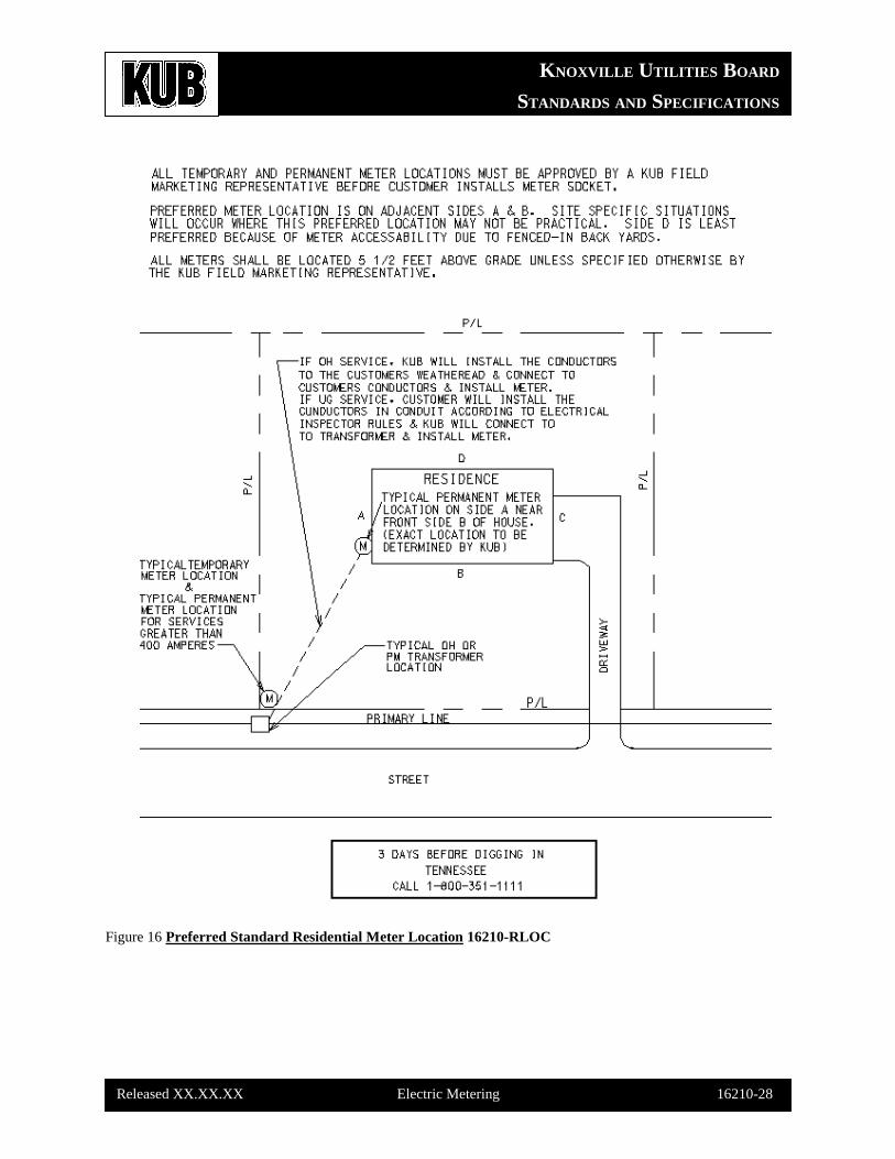
has been definitely approved by KUB’s Field Marketing Representative. The meter socket will be
plumb (5 to 6 feet above grade) and securely fastened to the external building wall, pole, pedestal,
or transformer (when applicable). A minimum of 2 feet of clear space measured from any part of
the meter socket to all conduits, pipe, walls, etc. must be maintained for servicing. Outdoor meters
will not be installed where they will interfere with traffic, sidewalks, driveways, or where they will
obstruct the opening of doors or windows, or in any location which may be considered hazardous or
cause damage to the metering equipment. Indoor meter installations are to be avoided.
1.6 Where service is supplied to individual customers located in a structure designed for multiple
occupancy, the individual meters will be grouped at a point nearest the service entrance attachment.
(See Article 370 of the National Electrical Code.) The mounting heights for multiple meter stacks
will be no lower than 3 feet from final grade to the center of the lowest meters and will be no higher
than 6 feet from grade to the center of the highest meters.
1.7 Current Transformers (CT’s) external to the meter housing are required if the customer’s service
(main) size is over 400 amperes (400A). The cable length between the CT’s and the meter should
never exceed 40 feet in length. KUB’s Field Marketing Representative must approve the CT’s
location.
KUB standard CT sizes KUB standard CT styles
300 / 5A (900A max.) PDMO (for pad-mounted transformers)
600 / 5A (1800A max.) PLMO (for pole & other mountings)
1500 / 5A (4500A. max.)
1.8 Meters and service equipment may be subjected to heavy fault currents in the event of a ground
fault. For this reason, it is imperative that all meter sockets and metal conduits be adequately
bonded to neutral and to ground.
1.9 The customer must not tamper or otherwise interfere with the proper operation of KUB’s meter or
other equipment. Only authorized KUB personnel are permitted to connect, disconnect, move, or
remove meters.
KNOXVILLE UTILITIES BOARD
STANDARDS AND SPECIFICATIONS
Released XX.XX.XX Electric Metering 16210-4
PART 2. PRODUCTS
Not Used.
PART 3. EXECUTION
3.1 SINGLE-PHASE METERING
KUB uses two basic types of electrical single-phase metering: Self-contained Metering &
Transformer-rated Metering.
SELF-CONTAINED METERING:
Electrical service sizes of “400A & below” are metered with Self-contained Metering, which means
that all associated hardware is self-contained within the meter housing. The meter “class
designation” (CL) denotes the maximum of the load range in amperes. KUB uses the CL200 (Form
2S) 240V self-contained meter for 2-wire, 120V, 30A services, and for 3-wire, 120/240V, 60A
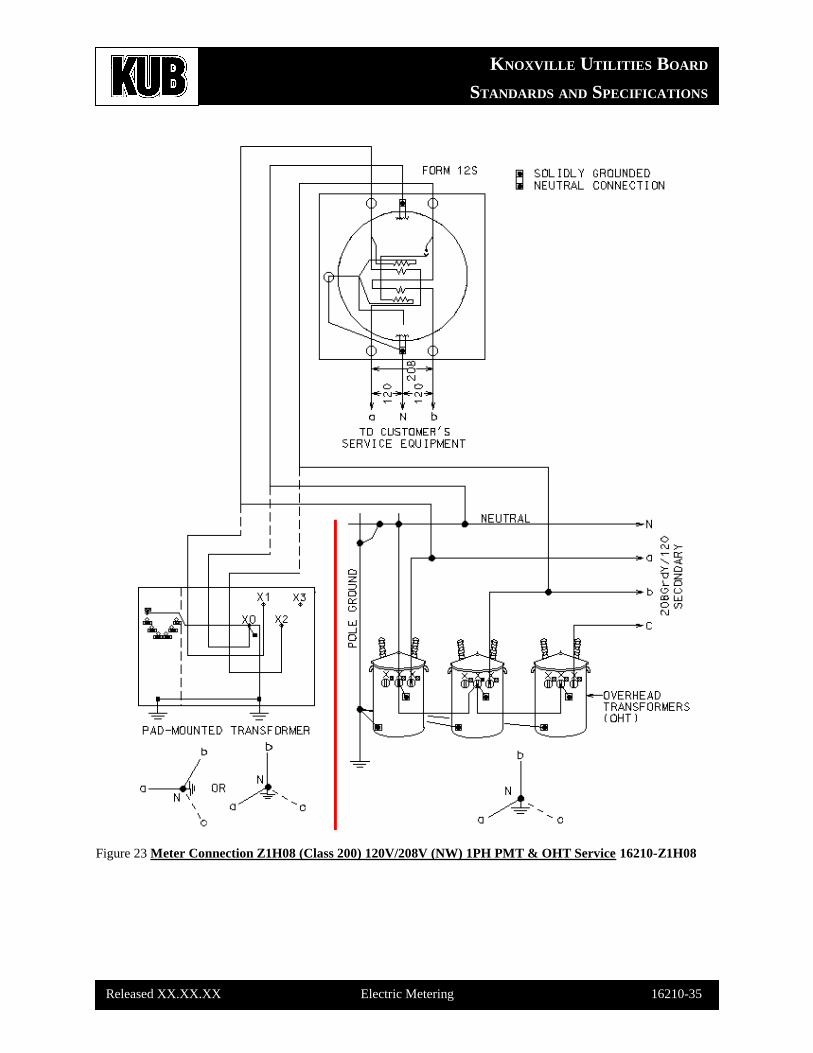
through 225A services. The CL200 (Form 12S) 120V self-contained meter is for 3-wire, 120/208V,
200A services. The CL320 (240V) is a newer socket type that requires special meter bases (5T and
7T types) for mounting. The current transformers are contained within the CL320 meter housing.
The customer is responsible for furnishing and installing the meter base (to KUB specifications),
and must have this installation inspected by the electrical inspector before KUB installs the meter.
TRANSFORMER-RATED METERING:
Electrical service sizes “greater than 400A” will be metered with appropriately-sized Current
Transformers (CT’s).
For KUB standard CT sizes & styles, see Section 16210-3, Paragraph 1.7.
For any commercial single-phase service with an estimated “demand” of “50kW (kilowatts) or
greater”, KUB will install an electronic meter with demand register instead of the typical rotating-
disk meter. The “demand” of a service is the amount of power delivered averaged over a specified
interval of time. The most common specified time interval used in commercial demand metering is
30 minutes.
See the “Meter Application Guide” on page 16210-6 for selection of the proper meter (and current
transformer) sizes for single-phase services.
KNOXVILLE UTILITIES BOARD
STANDARDS AND SPECIFICATIONS
Released XX.XX.XX Electric Metering 16210-5
See the following standard drawings for preferred residential meter location, meter drawing
symbols & single-phase meter wiring diagrams:
16210-RLOC (Preferred Residential Meter Locations)
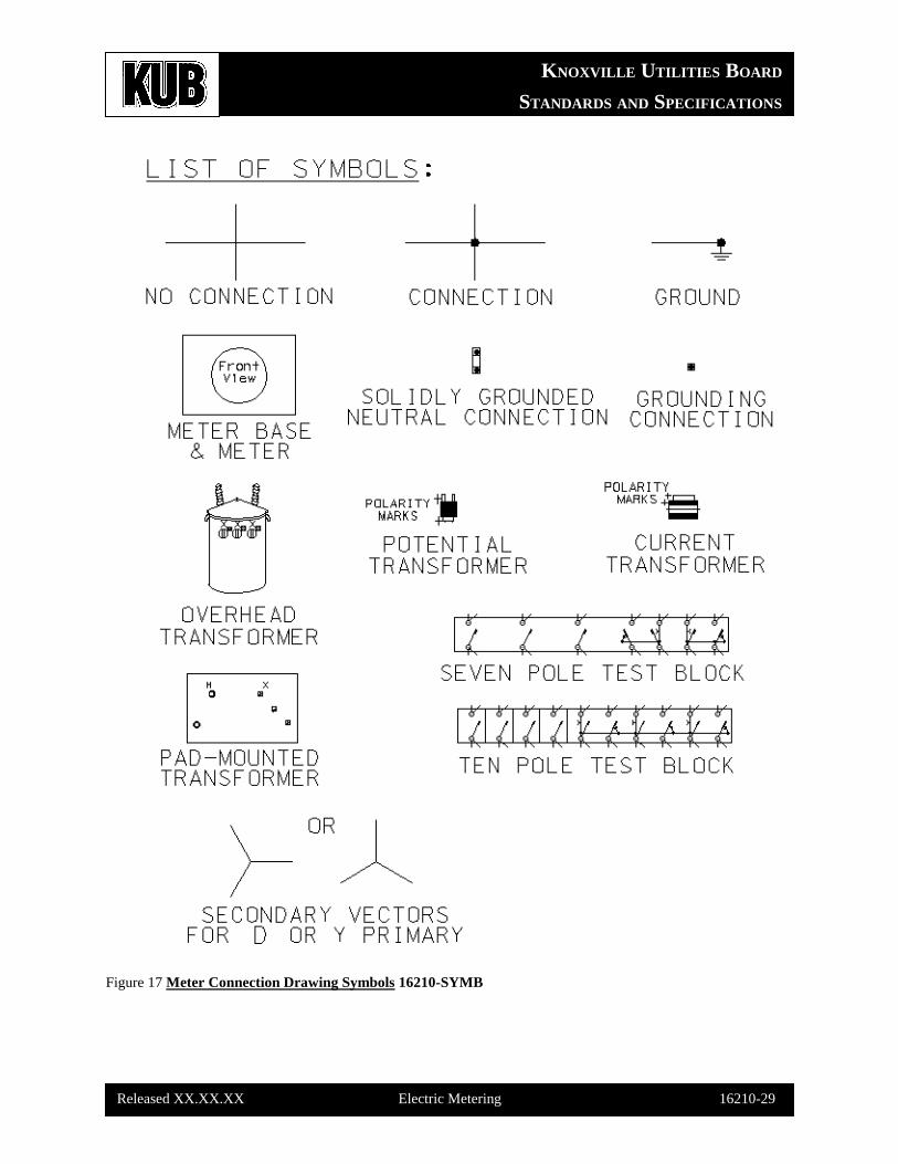
16210-SYMB (Meter Connection Drawing Symbols)
16210-J2E08 (Meter Wiring for 120V/240V, 1PH, 3W, 200A & Below Service) PMT & OHT
16210-K2E21 (Meter Wiring for 120V/240V, 1PH, 3W, 400A & 320A Service) PMT & OHT
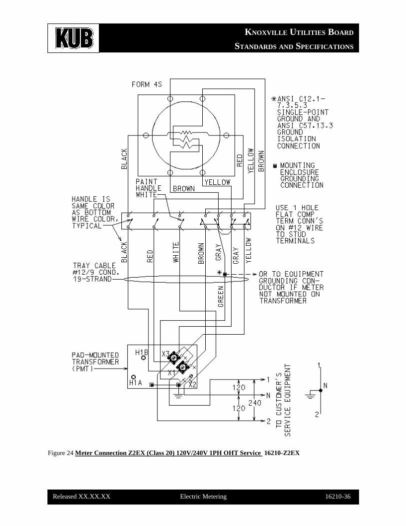
16210-Z2EX (Meter Wiring for 120V/240V, 1PH, 3W, CT-Rated Service) PMT
16210-Z2EXO (Meter Wiring for 120V/240V, 1PH, 3W, CT-Rated Service) OHT
16210-H1K08 (Meter Wiring for 120V, 1PH, 2W, 30A Service) PMT & OHT
16210-Z1H08 (Meter Wiring for 120V/208V, 1PH, 3W, 200A & Below Service) Overhead
16210-Z8KXX (Meter Wiring for 7.62kV, 1PH, 2W, Primary Service)
KNOXVILLE UTILITIES BOARD
STANDARDS AND SPECIFICATIONS
Released XX.XX.XX Electric Metering 16210-6
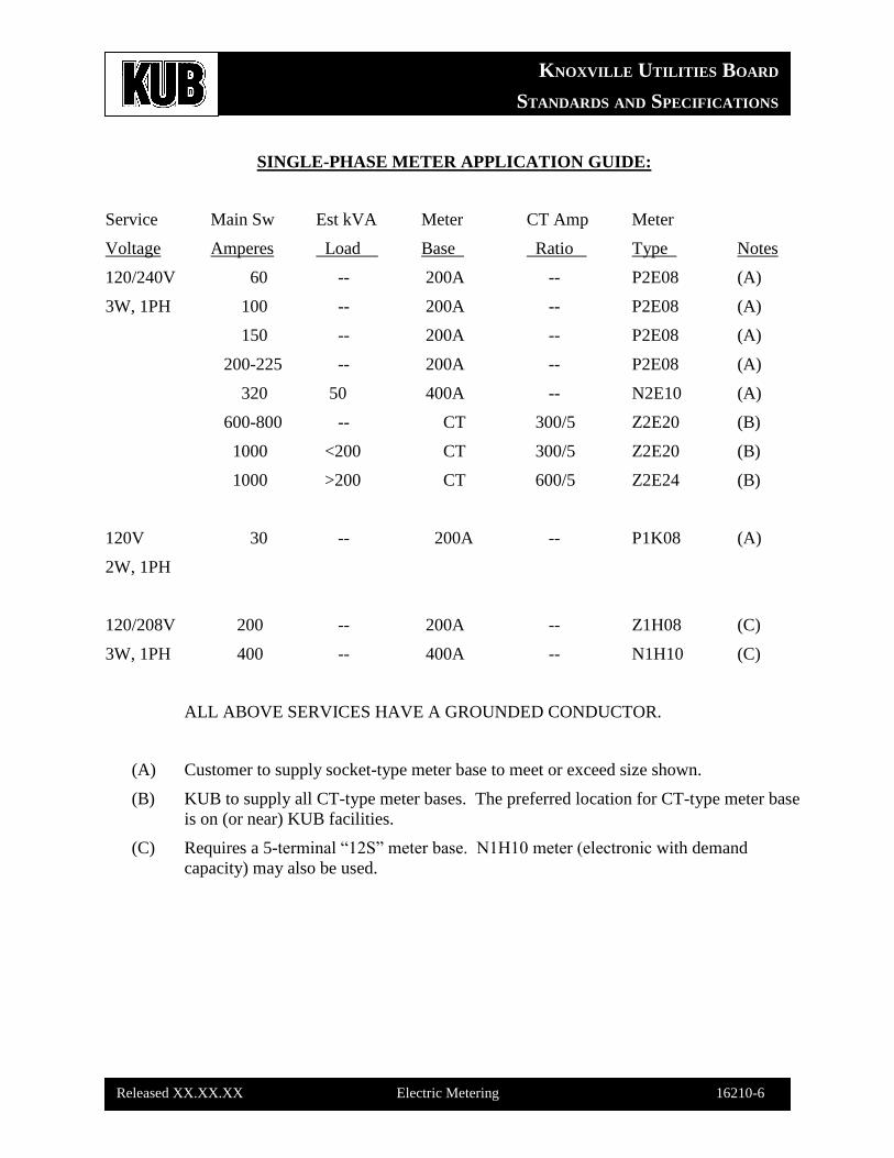
SINGLE-PHASE METER APPLICATION GUIDE:
Service Main Sw Est kVA Meter CT Amp Meter
Voltage Amperes Load Base Ratio Type Notes
120/240V 60 -- 200A -- P2E08 (A)
3W, 1PH 100 -- 200A -- P2E08 (A)
150 -- 200A -- P2E08 (A)
200-225 -- 200A -- P2E08 (A)
320 50 400A -- N2E10 (A)
600-800 -- CT 300/5 Z2E20 (B)
1000 <200 CT 300/5 Z2E20 (B)
1000 >200 CT 600/5 Z2E24 (B)
120V 30 -- 200A -- P1K08 (A)
2W, 1PH
120/208V 200 -- 200A -- Z1H08 (C)
3W, 1PH 400 -- 400A -- N1H10 (C)
ALL ABOVE SERVICES HAVE A GROUNDED CONDUCTOR.
(A) Customer to supply socket-type meter base to meet or exceed size shown.
(B) KUB to supply all CT-type meter bases. The preferred location for CT-type meter base
is on (or near) KUB facilities.
(C) Requires a 5-terminal “12S” meter base. N1H10 meter (electronic with demand
capacity) may also be used.
KNOXVILLE UTILITIES BOARD
STANDARDS AND SPECIFICATIONS
Released XX.XX.XX Electric Metering 16210-7
GENERAL: ELECTRICAL THREE-PHASE 3-WIRE METERING
Even though KUB no longer allows non-standard 3-phase 3-wire services for new customers, there
are still many existing 3-phase 3-wire services in KUB’s electric system. This section will cover
the specifications for the metering of these 3-wire (delta-configuration) services. The 2 types of
metering are Self-contained Metering & Transformer-rated Metering.
SELF-CONTAINED METERING:
Electrical service sizes of “400A & below” are metered with self-contained metering, which means
that all associated hardware (PT’s and/or CT’s) is self-contained within the meter housing.
All self-contained metering of 480V services must have a (KUB-approved) means of
disconnect ahead of the meter to facilitate the removal or replacement of the meter without
endangering metering personnel.
KUB’s Field Marketing Representative must approve all meter locations.
TRANSFORMER-RATED METERING:
Electric service sizes “greater than 400A” are metered with appropriately sized CT’s (Current
Transformers) & PT’s (Potential Transformers). KUB uses 3 basic sizes of CT’s are 300/5A (up to
900A maximum), 600/5A (up to 1800A maximum) & 1500/5A (up to 4500A maximum). Potential
Transformer (PT) size is 4/1 (or 480V/120V) for 480V services or 2.4/1 (or 277V/120V) for
277V/480V services. .
See the following standard drawings for 3-phase, 3-wire meter wiring diagrams:
16210-Z2C08 (Meter Wiring for 240V, 3PH, 3W, 200A & Below Service) OHT
16210-N2C21 (Meter Wiring for 240V, 3PH, 3W, 320A Service) OHT
16210-Z2CX (Meter Wiring for 240V, 3PH, 3W, CT-Rated Service) OHT
16210-Z4C08 (Meter Wiring for 480V, 3PH, 3W, 200A & Below Service) OHT
16210-N4C21 (Meter Wiring for 480V, 3PH, 3W, 400A Service) OHT
16210-Z4CX (Meter Wiring for 480V, 3PH, 3W, CT-Rated Service) OHT
KNOXVILLE UTILITIES BOARD
STANDARDS AND SPECIFICATIONS
Released XX.XX.XX Electric Metering 16210-8
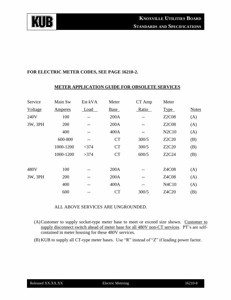
FOR ELECTRIC METER CODES, SEE PAGE 16210-2.
METER APPLICATION GUIDE FOR OBSOLETE SERVICES
Service Main Sw Est kVA Meter CT Amp Meter
Voltage Amperes Load Base Ratio Type Notes
240V 100 -- 200A -- Z2C08 (A)
3W, 3PH 200 -- 200A -- Z2C08 (A)
400 -- 400A -- N2C10 (A)
600-800 -- CT 300/5 Z2C20 (B)
1000-1200 <374 CT 300/5 Z2C20 (B)
1000-1200 >374 CT 600/5 Z2C24 (B)
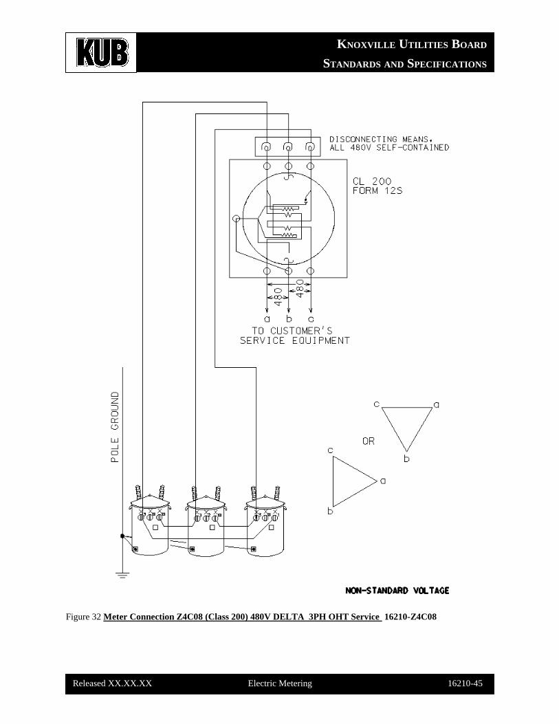
480V 100 -- 200A -- Z4C08 (A)
3W, 3PH 200 -- 200A -- Z4C08 (A)
400 -- 400A -- N4C10 (A)
600 -- CT 300/5 Z4C20 (B)
ALL ABOVE SERVICES ARE UNGROUNDED.
(A) Customer to supply socket-type meter base to meet or exceed size shown. Customer to
supply disconnect switch ahead of meter base for all 480V non-CT services. PT’s are self-
contained in meter housing for these 480V services.
(B) KUB to supply all CT-type meter bases. Use “R” instead of “Z” if leading power factor.
KNOXVILLE UTILITIES BOARD
STANDARDS AND SPECIFICATIONS
Released XX.XX.XX Electric Metering 16210-9
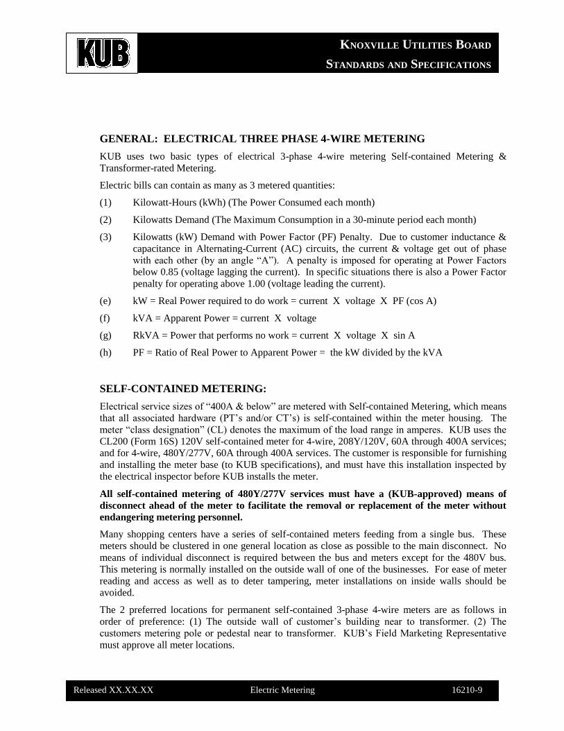
GENERAL: ELECTRICAL THREE PHASE 4-WIRE METERING
KUB uses two basic types of electrical 3-phase 4-wire metering Self-contained Metering &
Transformer-rated Metering.
Electric bills can contain as many as 3 metered quantities:
(1) Kilowatt-Hours (kWh) (The Power Consumed each month)
(2) Kilowatts Demand (The Maximum Consumption in a 30-minute period each month)
(3) Kilowatts (kW) Demand with Power Factor (PF) Penalty. Due to customer inductance &
capacitance in Alternating-Current (AC) circuits, the current & voltage get out of phase
with each other (by an angle “A”). A penalty is imposed for operating at Power Factors
below 0.85 (voltage lagging the current). In specific situations there is also a Power Factor
penalty for operating above 1.00 (voltage leading the current).
(e) kW = Real Power required to do work = current X voltage X PF (cos A)
(f) kVA = Apparent Power = current X voltage
(g) RkVA = Power that performs no work = current X voltage X sin A
(h) PF = Ratio of Real Power to Apparent Power = the kW divided by the kVA
SELF-CONTAINED METERING:
Electrical service sizes of “400A & below” are metered with Self-contained Metering, which means
that all associated hardware (PT’s and/or CT’s) is self-contained within the meter housing. The
meter “class designation” (CL) denotes the maximum of the load range in amperes. KUB uses the
CL200 (Form 16S) 120V self-contained meter for 4-wire, 208Y/120V, 60A through 400A services;
and for 4-wire, 480Y/277V, 60A through 400A services. The customer is responsible for furnishing
and installing the meter base (to KUB specifications), and must have this installation inspected by
the electrical inspector before KUB installs the meter.
All self-contained metering of 480Y/277V services must have a (KUB-approved) means of
disconnect ahead of the meter to facilitate the removal or replacement of the meter without
endangering metering personnel.
Many shopping centers have a series of self-contained meters feeding from a single bus. These
meters should be clustered in one general location as close as possible to the main disconnect. No
means of individual disconnect is required between the bus and meters except for the 480V bus.
This metering is normally installed on the outside wall of one of the businesses. For ease of meter
reading and access as well as to deter tampering, meter installations on inside walls should be
avoided.
The 2 preferred locations for permanent self-contained 3-phase 4-wire meters are as follows in
order of preference: (1) The outside wall of customer’s building near to transformer. (2) The
customers metering pole or pedestal near to transformer. KUB’s Field Marketing Representative
must approve all meter locations.
KNOXVILLE UTILITIES BOARD
STANDARDS AND SPECIFICATIONS
Released XX.XX.XX Electric Metering 16210-10
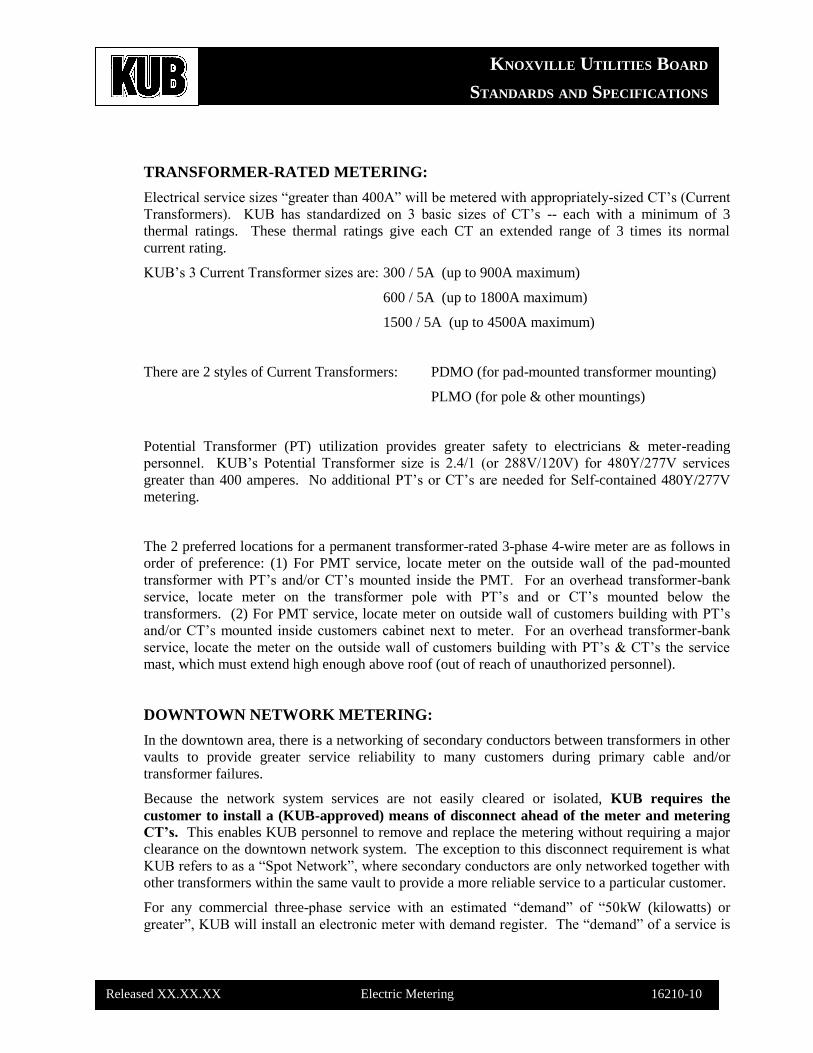
TRANSFORMER-RATED METERING:
Electrical service sizes “greater than 400A” will be metered with appropriately-sized CT’s (Current
Transformers). KUB has standardized on 3 basic sizes of CT’s -- each with a minimum of 3
thermal ratings. These thermal ratings give each CT an extended range of 3 times its normal
current rating.
KUB’s 3 Current Transformer sizes are: 300 / 5A (up to 900A maximum)
600 / 5A (up to 1800A maximum)
1500 / 5A (up to 4500A maximum)
There are 2 styles of Current Transformers: PDMO (for pad-mounted transformer mounting)
PLMO (for pole & other mountings)
Potential Transformer (PT) utilization provides greater safety to electricians & meter-reading
personnel. KUB’s Potential Transformer size is 2.4/1 (or 288V/120V) for 480Y/277V services
greater than 400 amperes. No additional PT’s or CT’s are needed for Self-contained 480Y/277V
metering.
The 2 preferred locations for a permanent transformer-rated 3-phase 4-wire meter are as follows in
order of preference: (1) For PMT service, locate meter on the outside wall of the pad-mounted
transformer with PT’s and/or CT’s mounted inside the PMT. For an overhead transformer-bank
service, locate meter on the transformer pole with PT’s and or CT’s mounted below the
transformers. (2) For PMT service, locate meter on outside wall of customers building with PT’s
and/or CT’s mounted inside customers cabinet next to meter. For an overhead transformer-bank
service, locate the meter on the outside wall of customers building with PT’s & CT’s the service
mast, which must extend high enough above roof (out of reach of unauthorized personnel).
DOWNTOWN NETWORK METERING:
In the downtown area, there is a networking of secondary conductors between transformers in other
vaults to provide greater service reliability to many customers during primary cable and/or
transformer failures.
Because the network system services are not easily cleared or isolated, KUB requires the
customer to install a (KUB-approved) means of disconnect ahead of the meter and metering
CT’s. This enables KUB personnel to remove and replace the metering without requiring a major
clearance on the downtown network system. The exception to this disconnect requirement is what
KUB refers to as a “Spot Network”, where secondary conductors are only networked together with
other transformers within the same vault to provide a more reliable service to a particular customer.
For any commercial three-phase service with an estimated “demand” of “50kW (kilowatts) or
greater”, KUB will install an electronic meter with demand register. The “demand” of a service is
KNOXVILLE UTILITIES BOARD
STANDARDS AND SPECIFICATIONS
Released XX.XX.XX Electric Metering 16210-11
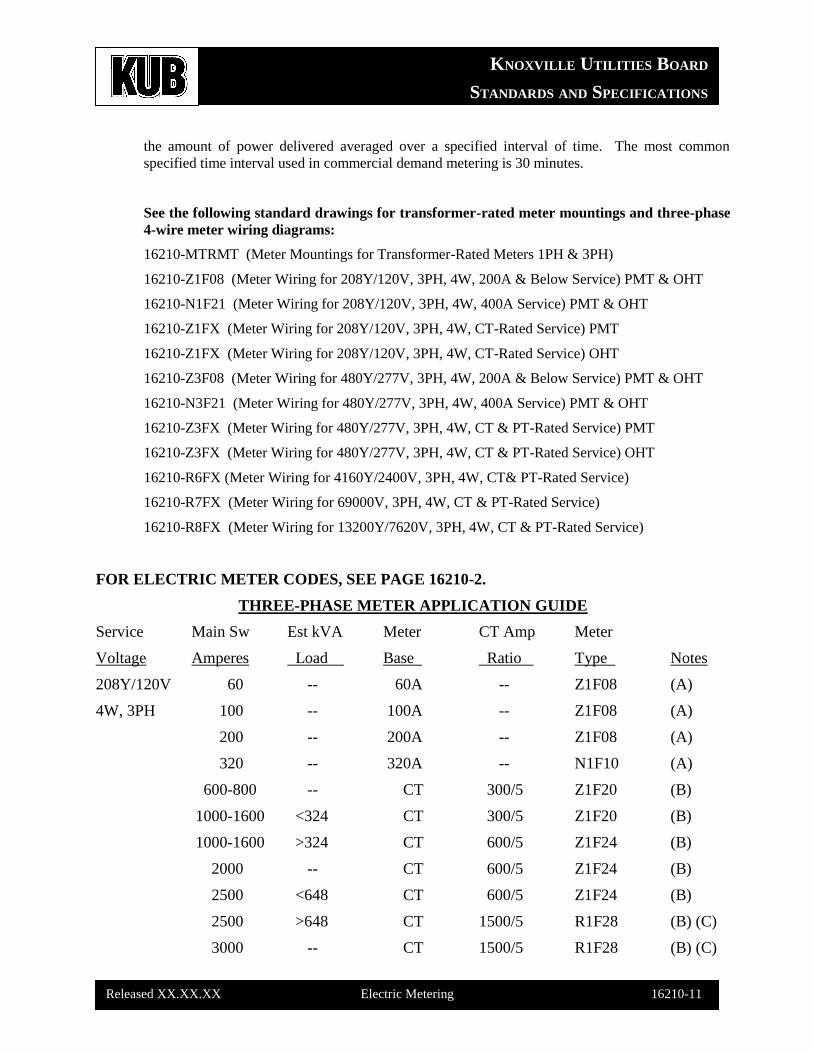
the amount of power delivered averaged over a specified interval of time. The most common
specified time interval used in commercial demand metering is 30 minutes.
See the following standard drawings for transformer-rated meter mountings and three-phase
4-wire meter wiring diagrams:
16210-MTRMT (Meter Mountings for Transformer-Rated Meters 1PH & 3PH)
16210-Z1F08 (Meter Wiring for 208Y/120V, 3PH, 4W, 200A & Below Service) PMT & OHT
16210-N1F21 (Meter Wiring for 208Y/120V, 3PH, 4W, 400A Service) PMT & OHT
16210-Z1FX (Meter Wiring for 208Y/120V, 3PH, 4W, CT-Rated Service) PMT
16210-Z1FX (Meter Wiring for 208Y/120V, 3PH, 4W, CT-Rated Service) OHT
16210-Z3F08 (Meter Wiring for 480Y/277V, 3PH, 4W, 200A & Below Service) PMT & OHT
16210-N3F21 (Meter Wiring for 480Y/277V, 3PH, 4W, 400A Service) PMT & OHT
16210-Z3FX (Meter Wiring for 480Y/277V, 3PH, 4W, CT & PT-Rated Service) PMT
16210-Z3FX (Meter Wiring for 480Y/277V, 3PH, 4W, CT & PT-Rated Service) OHT
16210-R6FX (Meter Wiring for 4160Y/2400V, 3PH, 4W, CT& PT-Rated Service)
16210-R7FX (Meter Wiring for 69000V, 3PH, 4W, CT & PT-Rated Service)
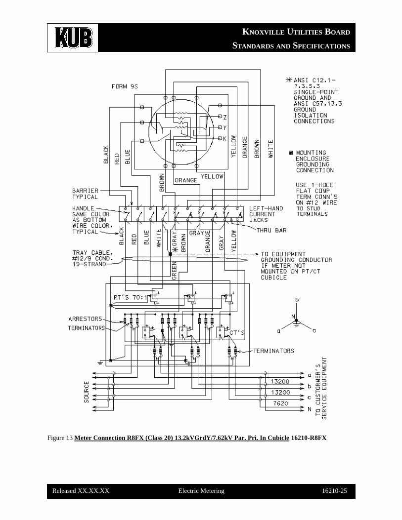
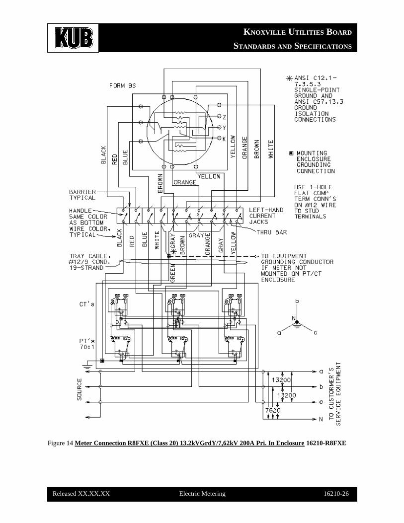
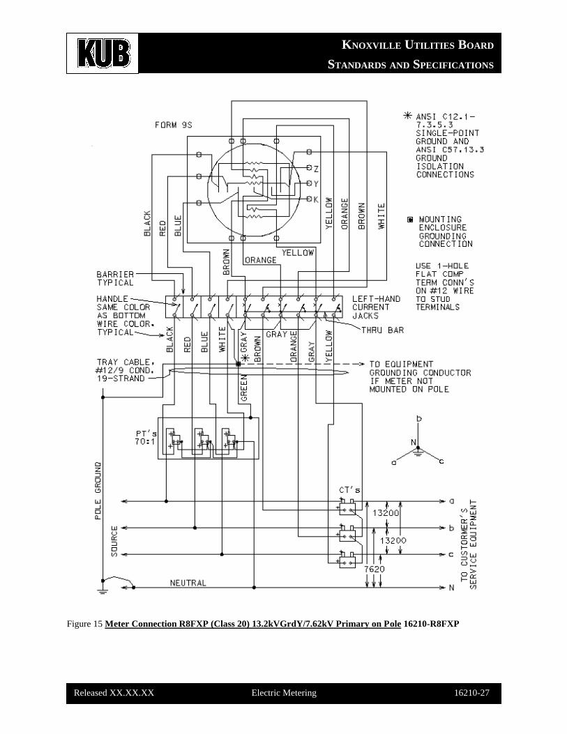
16210-R8FX (Meter Wiring for 13200Y/7620V, 3PH, 4W, CT & PT-Rated Service)
FOR ELECTRIC METER CODES, SEE PAGE 16210-2.
THREE-PHASE METER APPLICATION GUIDE
Service Main Sw Est kVA Meter CT Amp Meter
Voltage Amperes Load Base Ratio Type Notes
208Y/120V 60 -- 60A -- Z1F08 (A)
4W, 3PH 100 -- 100A -- Z1F08 (A)
200 -- 200A -- Z1F08 (A)
320 -- 320A -- N1F10 (A)
600-800 -- CT 300/5 Z1F20 (B)
1000-1600 <324 CT 300/5 Z1F20 (B)
1000-1600 >324 CT 600/5 Z1F24 (B)
2000 -- CT 600/5 Z1F24 (B)
2500 <648 CT 600/5 Z1F24 (B)
2500 >648 CT 1500/5 R1F28 (B) (C)
3000 -- CT 1500/5 R1F28 (B) (C)
KNOXVILLE UTILITIES BOARD
STANDARDS AND SPECIFICATIONS
Released XX.XX.XX Electric Metering 16210-12
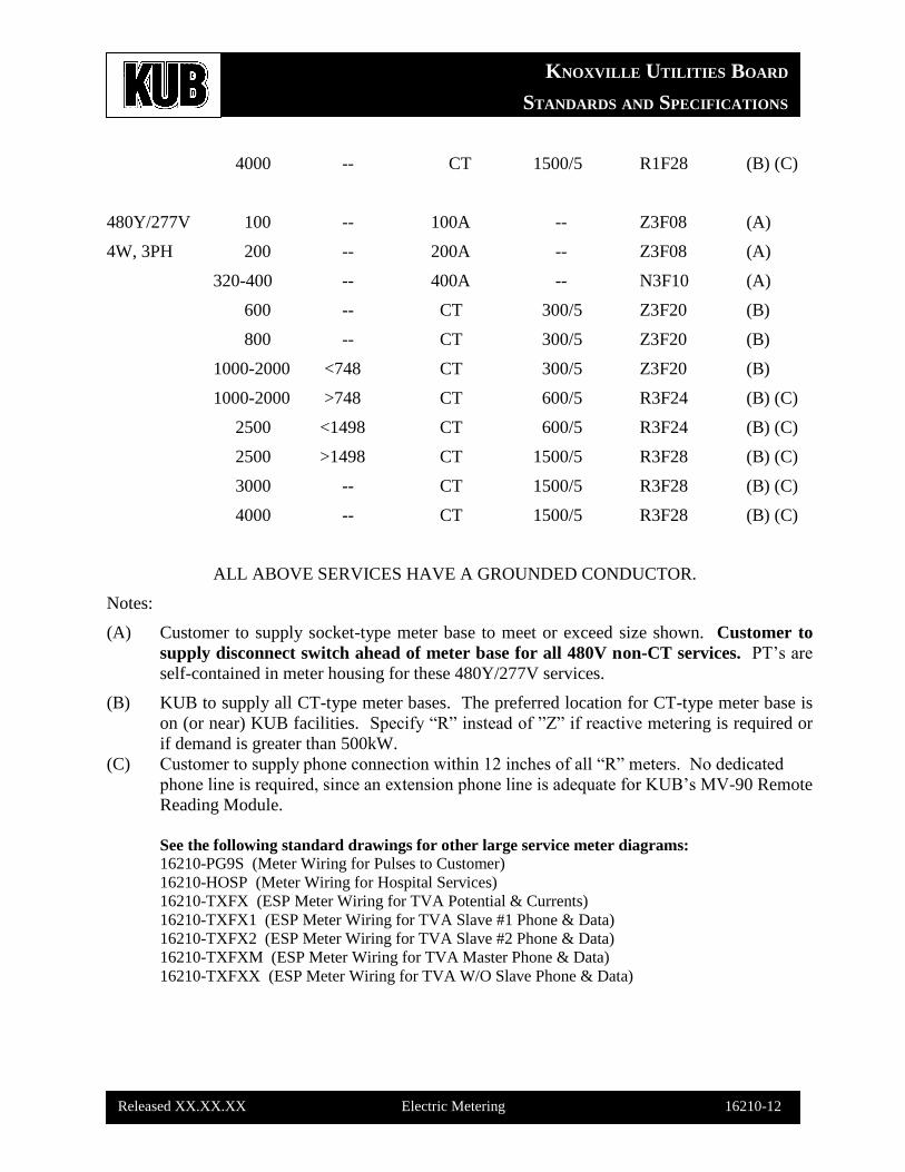
4000 -- CT 1500/5 R1F28 (B) (C)
480Y/277V 100 -- 100A -- Z3F08 (A)
4W, 3PH 200 -- 200A -- Z3F08 (A)
320-400 -- 400A -- N3F10 (A)
600 -- CT 300/5 Z3F20 (B)
800 -- CT 300/5 Z3F20 (B)
1000-2000 <748 CT 300/5 Z3F20 (B)
1000-2000 >748 CT 600/5 R3F24 (B) (C)
2500 <1498 CT 600/5 R3F24 (B) (C)
2500 >1498 CT 1500/5 R3F28 (B) (C)
3000 -- CT 1500/5 R3F28 (B) (C)
4000 -- CT 1500/5 R3F28 (B) (C)
ALL ABOVE SERVICES HAVE A GROUNDED CONDUCTOR.
Notes:
(A) Customer to supply socket-type meter base to meet or exceed size shown. Customer to
supply disconnect switch ahead of meter base for all 480V non-CT services. PT’s are
self-contained in meter housing for these 480Y/277V services.
(B) KUB to supply all CT-type meter bases. The preferred location for CT-type meter base is
on (or near) KUB facilities. Specify “R” instead of ”Z” if reactive metering is required or
if demand is greater than 500kW.
(C) Customer to supply phone connection within 12 inches of all “R” meters. No dedicated
phone line is required, since an extension phone line is adequate for KUB’s MV-90 Remote
Reading Module.
See the following standard drawings for other large service meter diagrams:
16210-PG9S (Meter Wiring for Pulses to Customer)
16210-HOSP (Meter Wiring for Hospital Services)
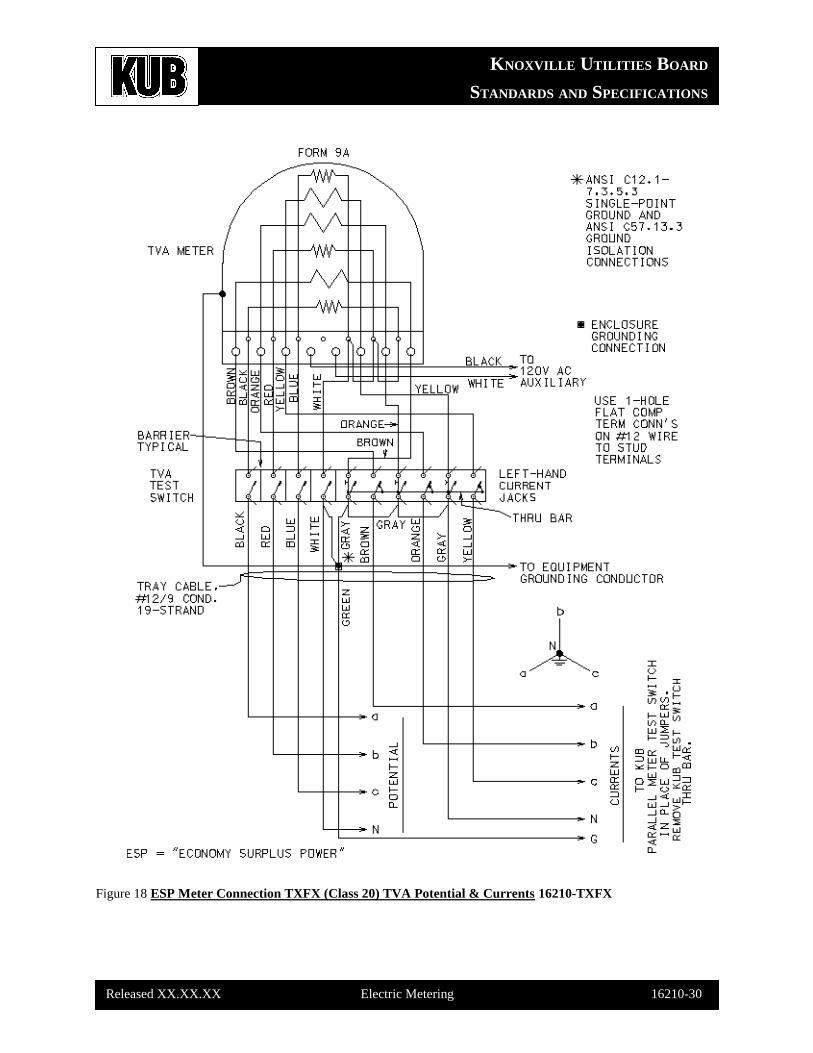
16210-TXFX (ESP Meter Wiring for TVA Potential & Currents)
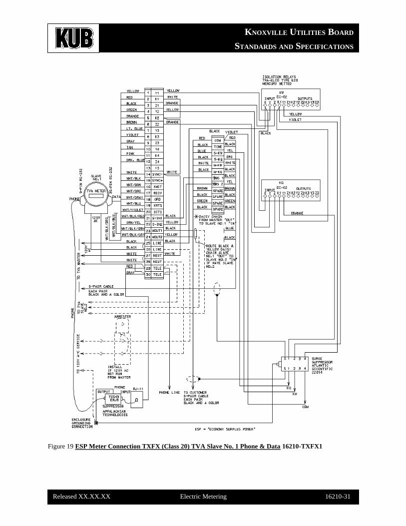
16210-TXFX1 (ESP Meter Wiring for TVA Slave #1 Phone & Data)
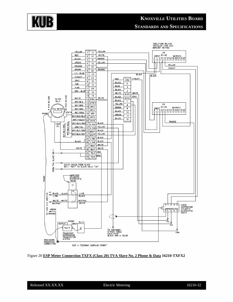
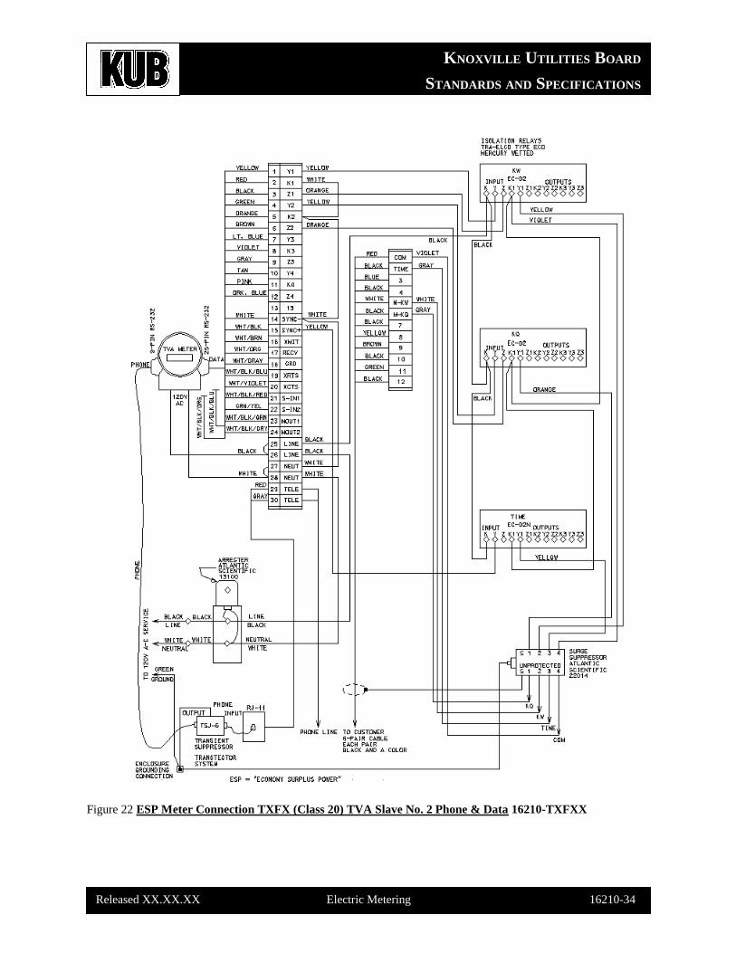
16210-TXFX2 (ESP Meter Wiring for TVA Slave #2 Phone & Data)
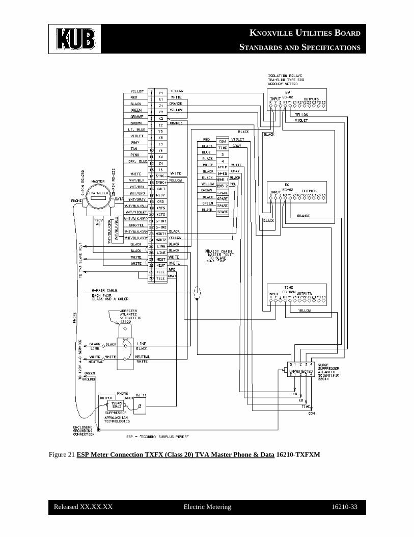
16210-TXFXM (ESP Meter Wiring for TVA Master Phone & Data)
16210-TXFXX (ESP Meter Wiring for TVA W/O Slave Phone & Data)
KNOXVILLE UTILITIES BOARD
STANDARDS AND SPECIFICATIONS
Released XX.XX.XX Electric Metering 16210-13
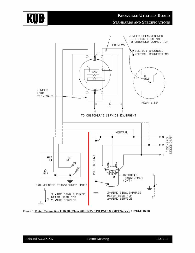
Figure 1 Meter Connection H1K08 (Class 200) 120V 1PH PMT & OHT Service 16210-H1K08
KNOXVILLE UTILITIES BOARD
STANDARDS AND SPECIFICATIONS
Released XX.XX.XX Electric Metering 16210-14
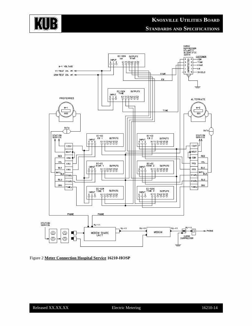
Figure 2 Meter Connection Hospital Service 16210-HOSP
KNOXVILLE UTILITIES BOARD
STANDARDS AND SPECIFICATIONS
Released XX.XX.XX Electric Metering 16210-15
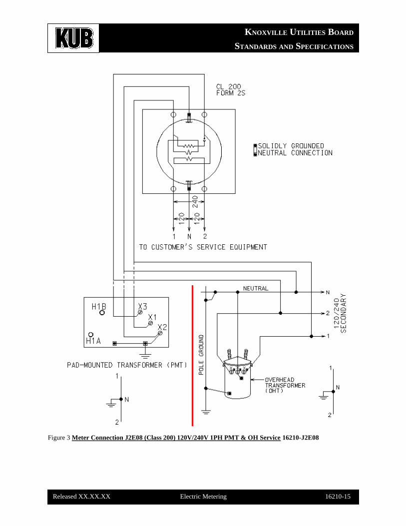
Figure 3 Meter Connection J2E08 (Class 200) 120V/240V 1PH PMT & OH Service 16210-J2E08
KNOXVILLE UTILITIES BOARD
STANDARDS AND SPECIFICATIONS
Released XX.XX.XX Electric Metering 16210-16
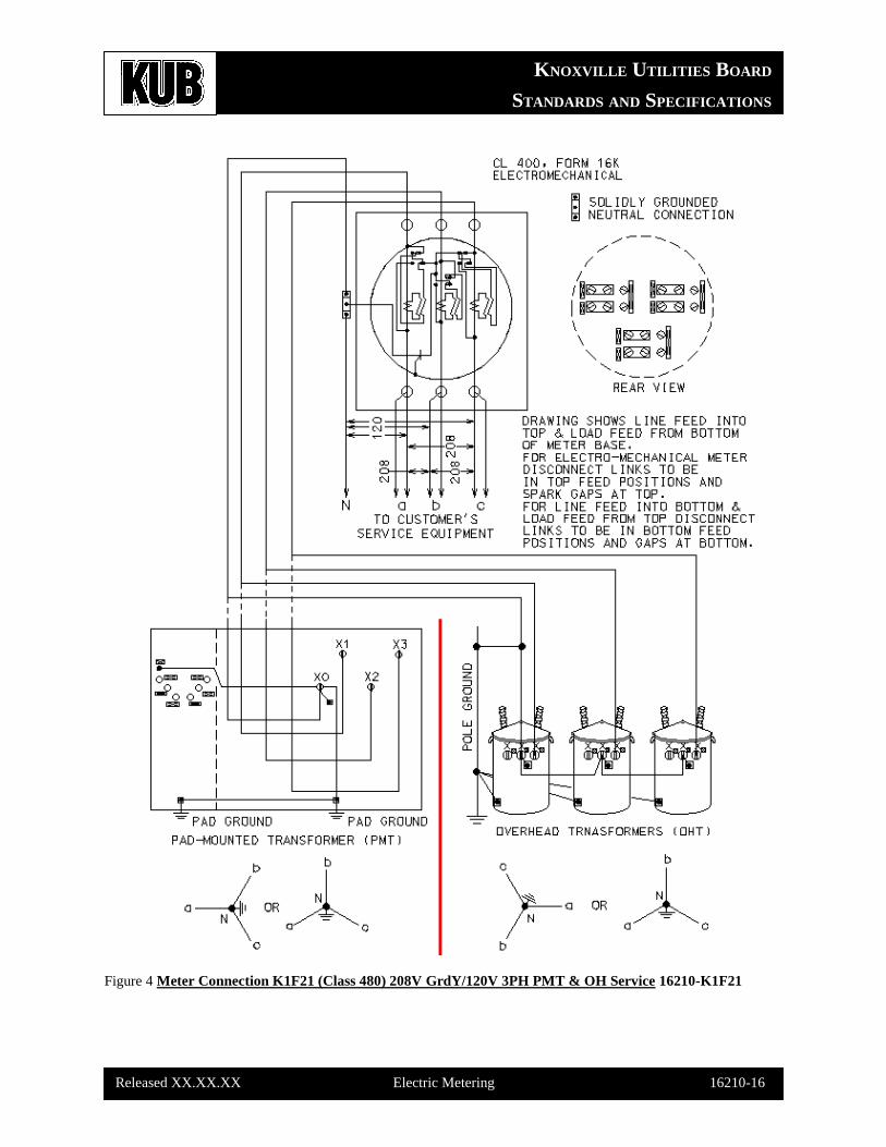
Figure 4 Meter Connection K1F21 (Class 480) 208V GrdY/120V 3PH PMT & OH Service 16210-K1F21
KNOXVILLE UTILITIES BOARD
STANDARDS AND SPECIFICATIONS
Released XX.XX.XX Electric Metering 16210-17
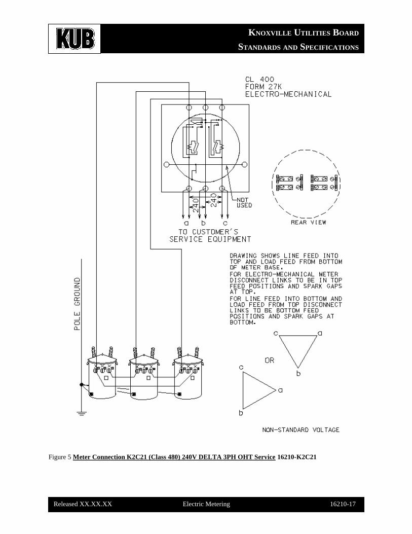
Figure 5 Meter Connection K2C21 (Class 480) 240V DELTA 3PH OHT Service 16210-K2C21
KNOXVILLE UTILITIES BOARD
STANDARDS AND SPECIFICATIONS
Released XX.XX.XX Electric Metering 16210-18
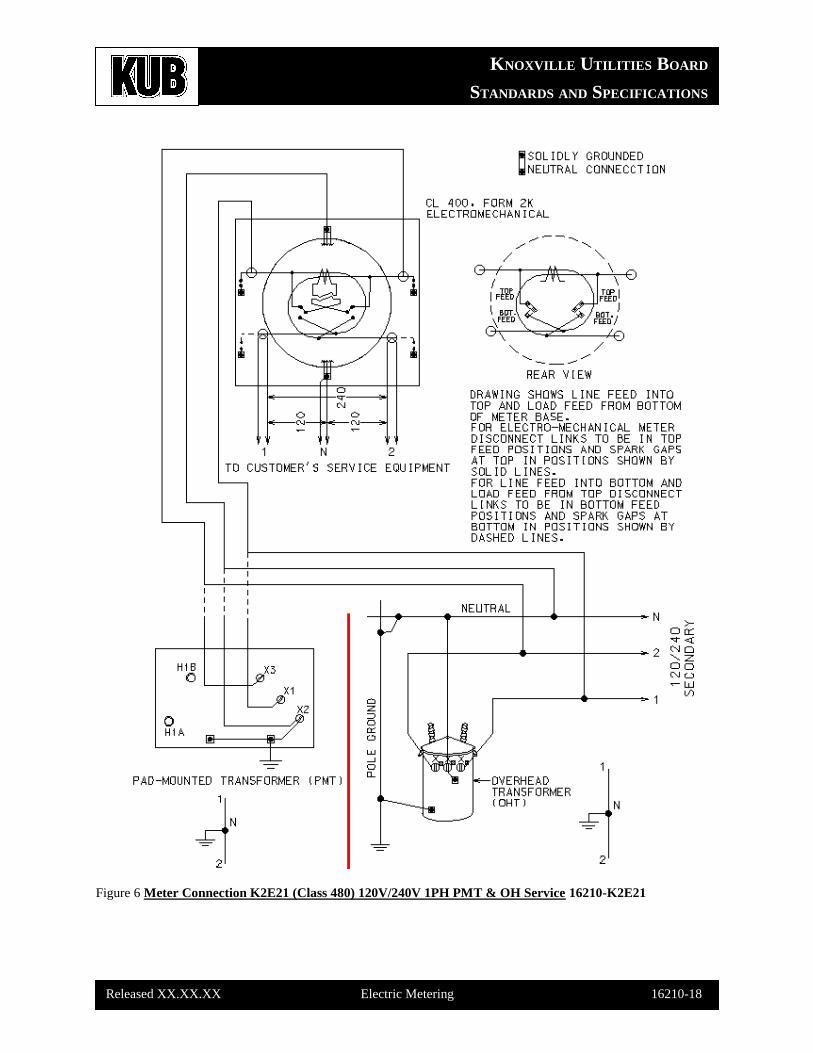
Figure 6 Meter Connection K2E21 (Class 480) 120V/240V 1PH PMT & OH Service 16210-K2E21
KNOXVILLE UTILITIES BOARD
STANDARDS AND SPECIFICATIONS
Released XX.XX.XX Electric Metering 16210-19
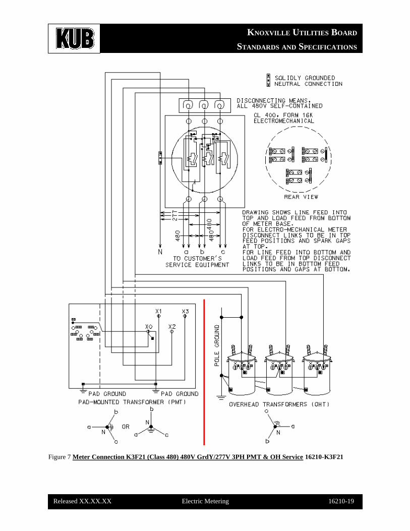
Figure 7 Meter Connection K3F21 (Class 480) 480V GrdY/277V 3PH PMT & OH Service 16210-K3F21
KNOXVILLE UTILITIES BOARD
STANDARDS AND SPECIFICATIONS
Released XX.XX.XX Electric Metering 16210-20
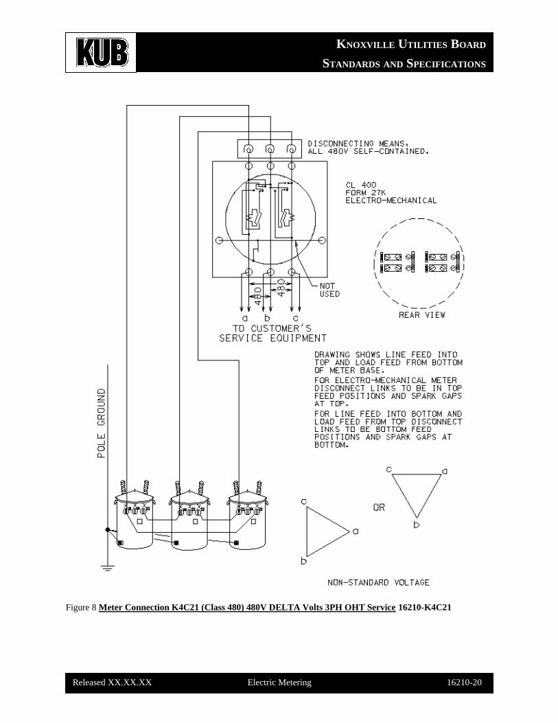
Figure 8 Meter Connection K4C21 (Class 480) 480V DELTA Volts 3PH OHT Service 16210-K4C21
KNOXVILLE UTILITIES BOARD
STANDARDS AND SPECIFICATIONS
Released XX.XX.XX Electric Metering 16210-21
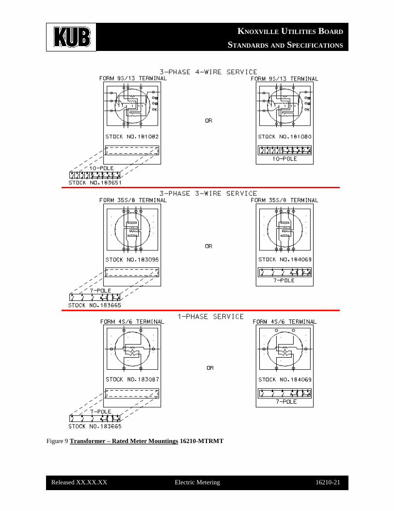
Figure 9 Transformer – Rated Meter Mountings 16210-MTRMT
KNOXVILLE UTILITIES BOARD
STANDARDS AND SPECIFICATIONS
Released XX.XX.XX Electric Metering 16210-22
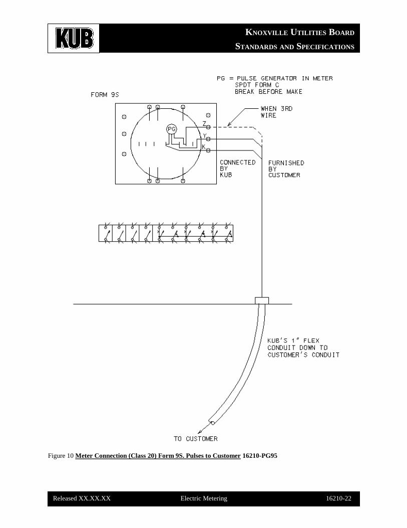
Figure 10 Meter Connection (Class 20) Form 9S. Pulses to Customer 16210-PG95

KNOXVILLE UTILITIES BOARD
STANDARDS AND SPECIFICATIONS
Released XX.XX.XX Electric Metering 16210-23
Figure 11 Meter Connection R6FX (Class 20) 4.16kV GrdY/2.4kV Primary on Pole 16210-R6FX
KNOXVILLE UTILITIES BOARD
STANDARDS AND SPECIFICATIONS
Released XX.XX.XX Electric Metering 16210-24
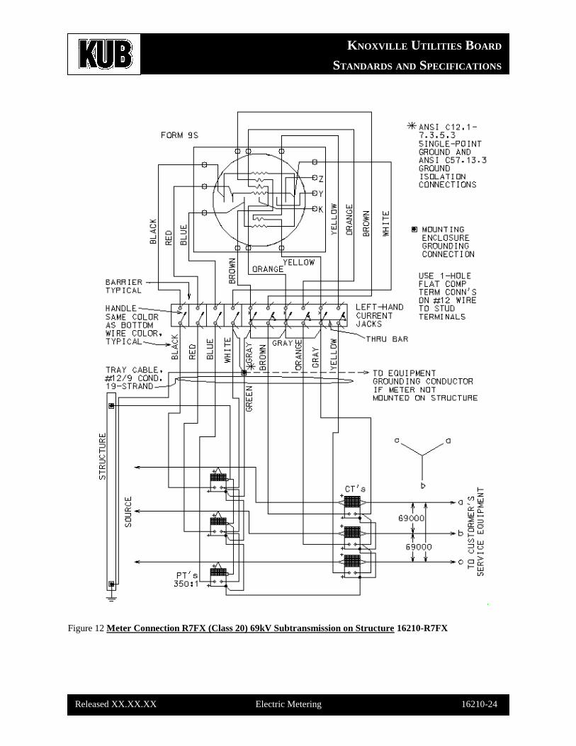
Figure 12 Meter Connection R7FX (Class 20) 69kV Subtransmission on Structure 16210-R7FX
KNOXVILLE UTILITIES BOARD
STANDARDS AND SPECIFICATIONS
Released XX.XX.XX Electric Metering 16210-25
Figure 13 Meter Connection R8FX (Class 20) 13.2kVGrdY/7.62kV Par. Pri. In Cubicle 16210-R8FX
KNOXVILLE UTILITIES BOARD
STANDARDS AND SPECIFICATIONS
Released XX.XX.XX Electric Metering 16210-26
Figure 14 Meter Connection R8FXE (Class 20) 13.2kVGrdY/7,62kV 200A Pri. In Enclosure 16210-R8FXE
KNOXVILLE UTILITIES BOARD
STANDARDS AND SPECIFICATIONS
Released XX.XX.XX Electric Metering 16210-27
Figure 15 Meter Connection R8FXP (Class 20) 13.2kVGrdY/7.62kV Primary on Pole 16210-R8FXP
KNOXVILLE UTILITIES BOARD
STANDARDS AND SPECIFICATIONS
Released XX.XX.XX Electric Metering 16210-28
Figure 16 Preferred Standard Residential Meter Location 16210-RLOC
KNOXVILLE UTILITIES BOARD
STANDARDS AND SPECIFICATIONS
Released XX.XX.XX Electric Metering 16210-29
Figure 17 Meter Connection Drawing Symbols 16210-SYMB
KNOXVILLE UTILITIES BOARD
STANDARDS AND SPECIFICATIONS
Released XX.XX.XX Electric Metering 16210-30
Figure 18 ESP Meter Connection TXFX (Class 20) TVA Potential & Currents 16210-TXFX
KNOXVILLE UTILITIES BOARD
STANDARDS AND SPECIFICATIONS
Released XX.XX.XX Electric Metering 16210-31
Figure 19 ESP Meter Connection TXFX (Class 20) TVA Slave No. 1 Phone & Data 16210-TXFX1
KNOXVILLE UTILITIES BOARD
STANDARDS AND SPECIFICATIONS
Released XX.XX.XX Electric Metering 16210-32
Figure 20 ESP Meter Connection TXFX (Class 20) TVA Slave No. 2 Phone & Data 16210-TXFX2
KNOXVILLE UTILITIES BOARD
STANDARDS AND SPECIFICATIONS
Released XX.XX.XX Electric Metering 16210-33
Figure 21 ESP Meter Connection TXFX (Class 20) TVA Master Phone & Data 16210-TXFXM
KNOXVILLE UTILITIES BOARD
STANDARDS AND SPECIFICATIONS
Released XX.XX.XX Electric Metering 16210-34
Figure 22 ESP Meter Connection TXFX (Class 20) TVA Slave No. 2 Phone & Data 16210-TXFXX
KNOXVILLE UTILITIES BOARD
STANDARDS AND SPECIFICATIONS
Released XX.XX.XX Electric Metering 16210-35
Figure 23 Meter Connection Z1H08 (Class 200) 120V/208V (NW) 1PH PMT & OHT Service 16210-Z1H08
KNOXVILLE UTILITIES BOARD
STANDARDS AND SPECIFICATIONS
Released XX.XX.XX Electric Metering 16210-36
Figure 24 Meter Connection Z2EX (Class 20) 120V/240V 1PH OHT Service 16210-Z2EX
KNOXVILLE UTILITIES BOARD
STANDARDS AND SPECIFICATIONS
Released XX.XX.XX Electric Metering 16210-37
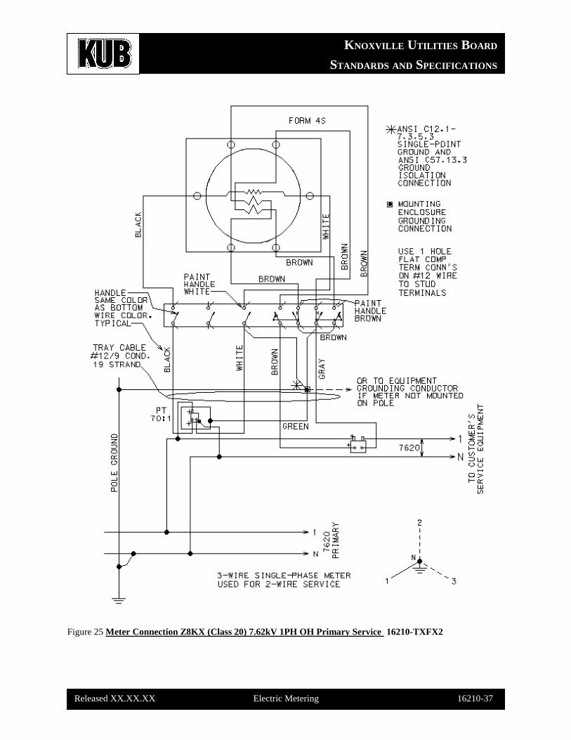
Figure 25 Meter Connection Z8KX (Class 20) 7.62kV 1PH OH Primary Service 16210-TXFX2
KNOXVILLE UTILITIES BOARD
STANDARDS AND SPECIFICATIONS
Released XX.XX.XX Electric Metering 16210-38
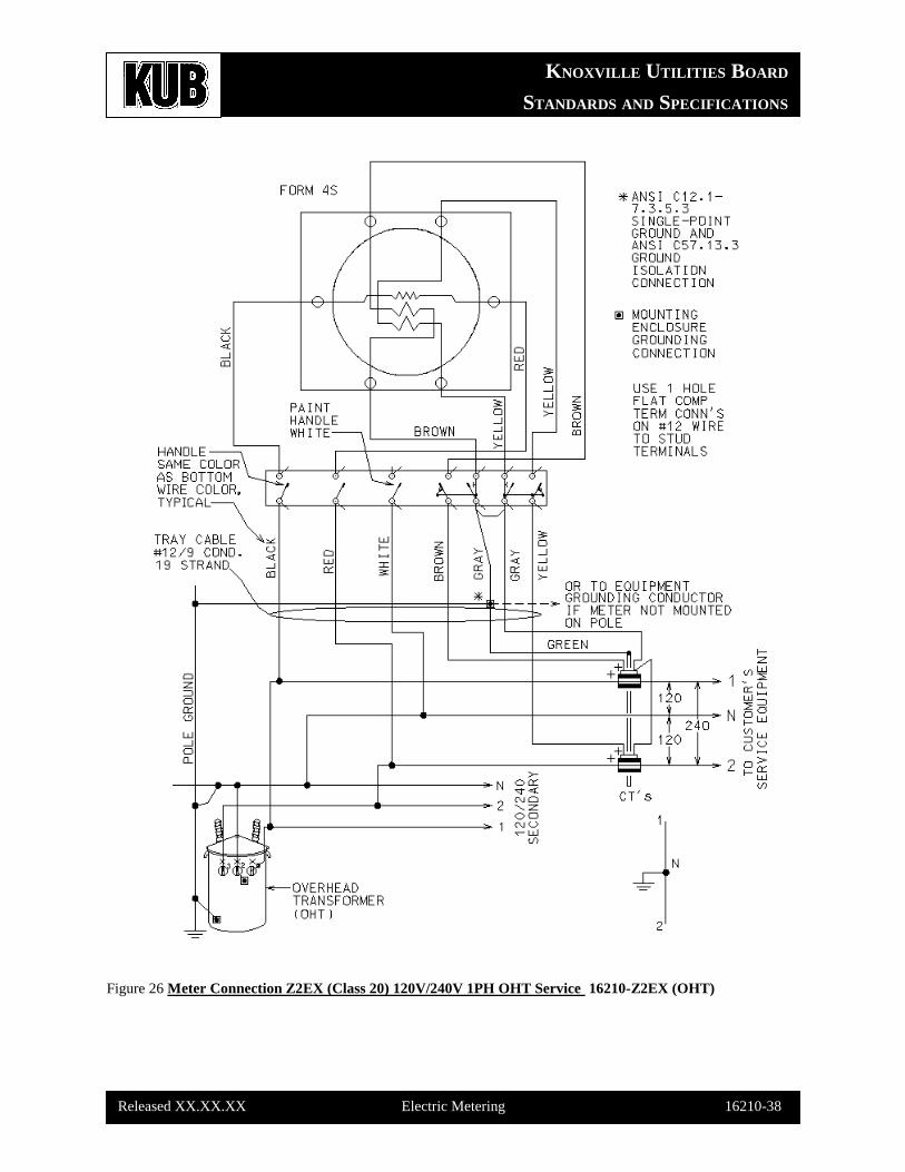
Figure 26 Meter Connection Z2EX (Class 20) 120V/240V 1PH OHT Service 16210-Z2EX (OHT)
KNOXVILLE UTILITIES BOARD
STANDARDS AND SPECIFICATIONS
Released XX.XX.XX Electric Metering 16210-39
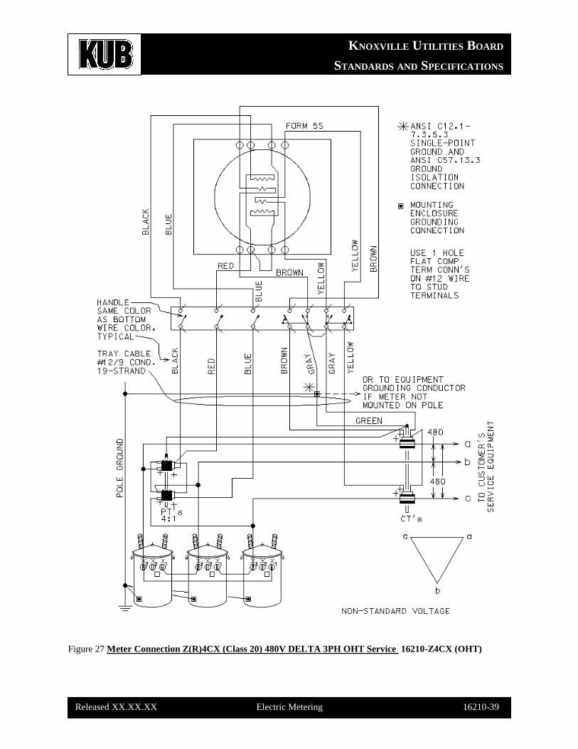
Figure 27 Meter Connection Z(R)4CX (Class 20) 480V DELTA 3PH OHT Service 16210-Z4CX (OHT)
KNOXVILLE UTILITIES BOARD
STANDARDS AND SPECIFICATIONS
Released XX.XX.XX Electric Metering 16210-40
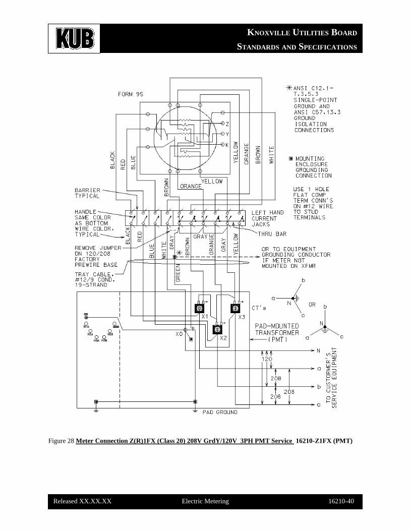
Figure 28 Meter Connection Z(R)1FX (Class 20) 208V GrdY/120V 3PH PMT Service 16210-Z1FX (PMT)
KNOXVILLE UTILITIES BOARD
STANDARDS AND SPECIFICATIONS
Released XX.XX.XX Electric Metering 16210-41
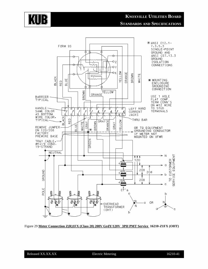
Figure 29 Meter Connection Z(R)1FX (Class 20) 208V GrdY/120V 3PH PMT Service 16210-Z1FX (OHT)
KNOXVILLE UTILITIES BOARD
STANDARDS AND SPECIFICATIONS
Released XX.XX.XX Electric Metering 16210-42
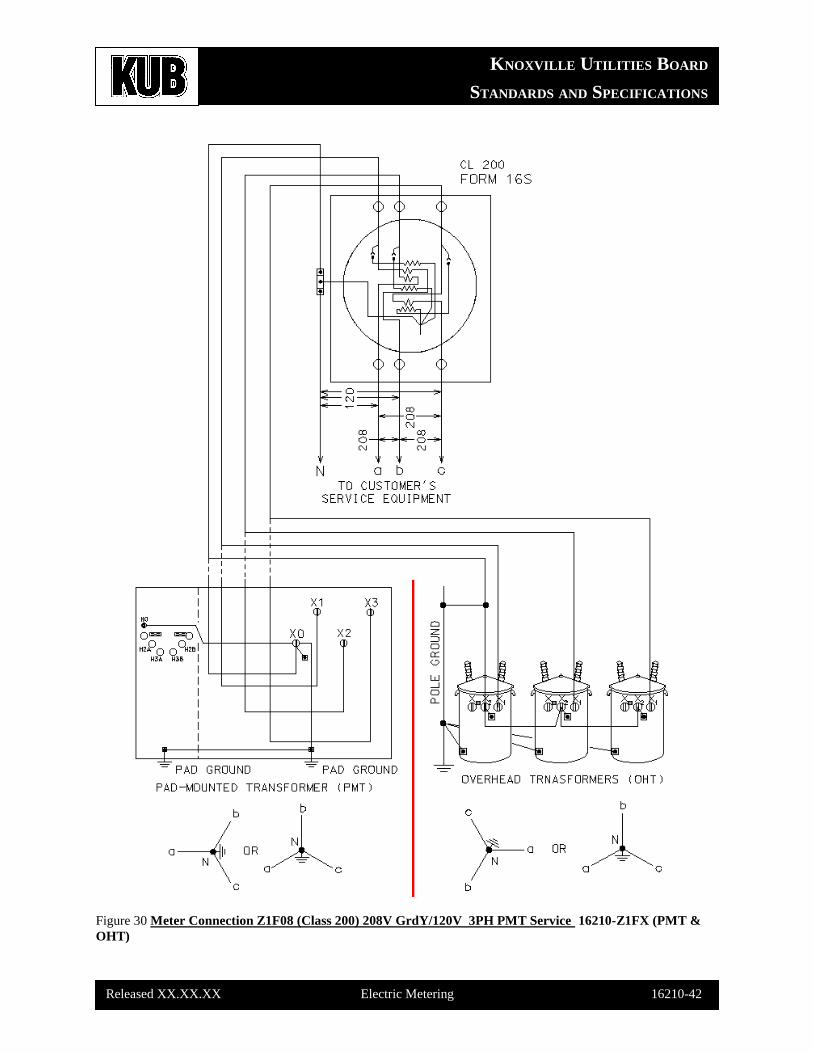
Figure 30 Meter Connection Z1F08 (Class 200) 208V GrdY/120V 3PH PMT Service 16210-Z1FX (PMT &
OHT)
KNOXVILLE UTILITIES BOARD
STANDARDS AND SPECIFICATIONS
Released XX.XX.XX Electric Metering 16210-43
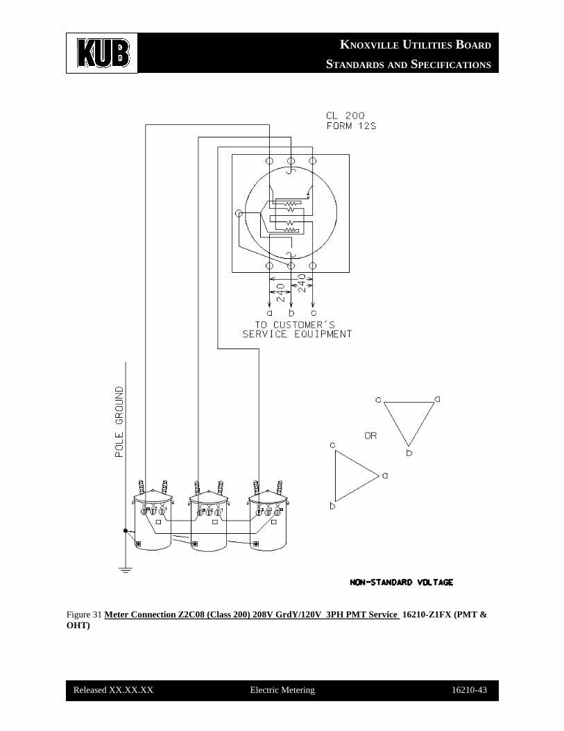
Figure 31 Meter Connection Z2C08 (Class 200) 208V GrdY/120V 3PH PMT Service 16210-Z1FX (PMT &
OHT)
KNOXVILLE UTILITIES BOARD
STANDARDS AND SPECIFICATIONS
Released XX.XX.XX Electric Metering 16210-44
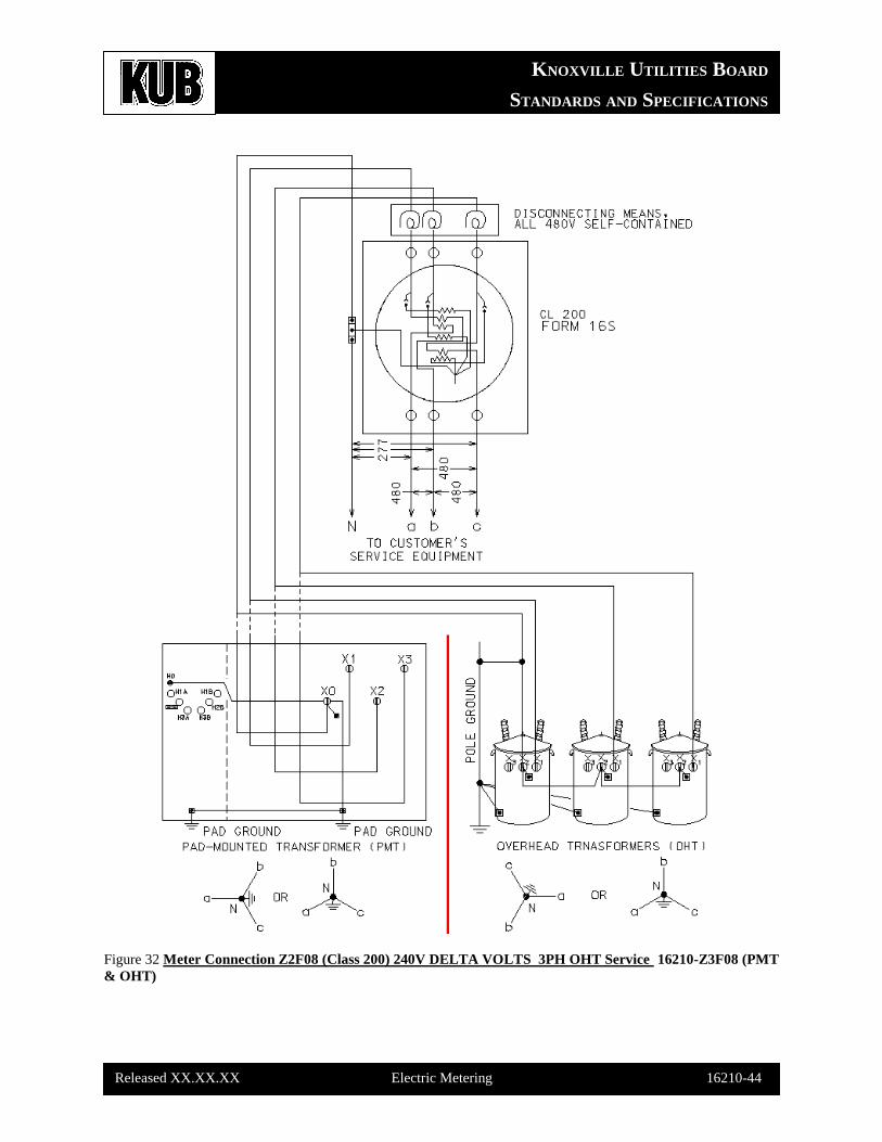
Figure 32 Meter Connection Z2F08 (Class 200) 240V DELTA VOLTS 3PH OHT Service 16210-Z3F08 (PMT
& OHT)
KNOXVILLE UTILITIES BOARD
STANDARDS AND SPECIFICATIONS
Released XX.XX.XX Electric Metering 16210-45
Figure 32 Meter Connection Z4C08 (Class 200) 480V DELTA 3PH OHT Service 16210-Z4C08
KNOXVILLE UTILITIES BOARD
STANDARDS AND SPECIFICATIONS
Released XX.XX.XX Electric Metering 16210-46
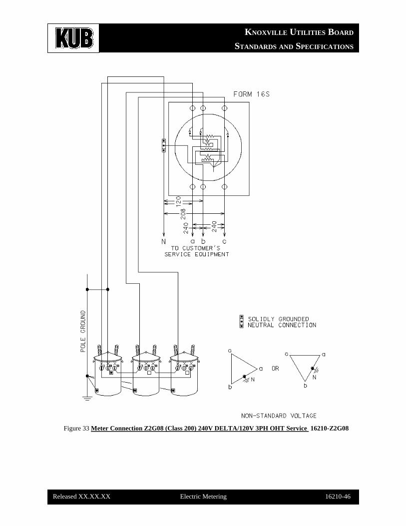
Figure 33 Meter Connection Z2G08 (Class 200) 240V DELTA/120V 3PH OHT Service 16210-Z2G08
KNOXVILLE UTILITIES BOARD
STANDARDS AND SPECIFICATIONS
Released XX.XX.XX Electric Metering 16210-47
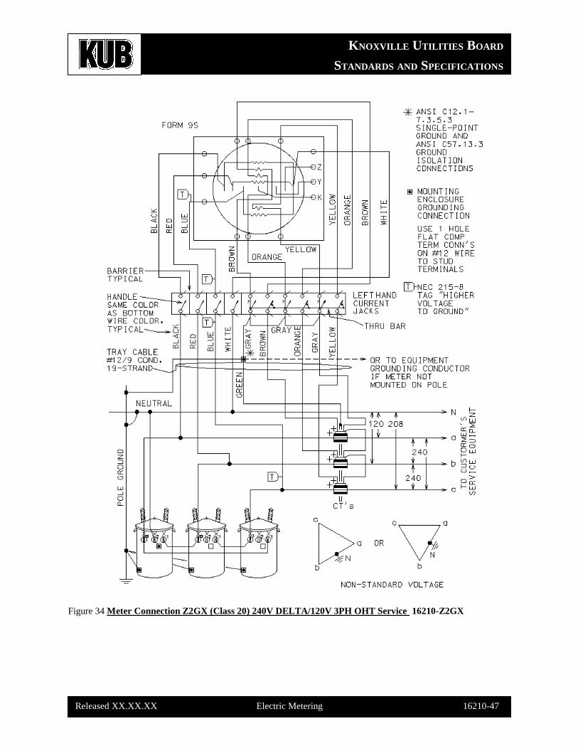
Figure 34 Meter Connection Z2GX (Class 20) 240V DELTA/120V 3PH OHT Service 16210-Z2GX
KNOXVILLE UTILITIES BOARD
STANDARDS AND SPECIFICATIONS
Released XX.XX.XX Electric Metering 16210-48
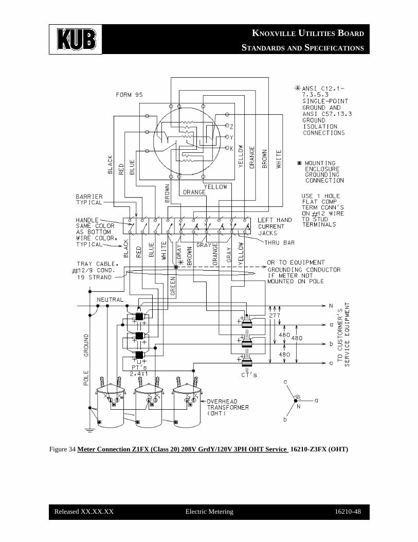
Figure 34 Meter Connection Z1FX (Class 20) 208V GrdY/120V 3PH OHT Service 16210-Z3FX (OHT)
KNOXVILLE UTILITIES BOARD
STANDARDS AND SPECIFICATIONS
Released XX.XX.XX Electric Metering 16210-49
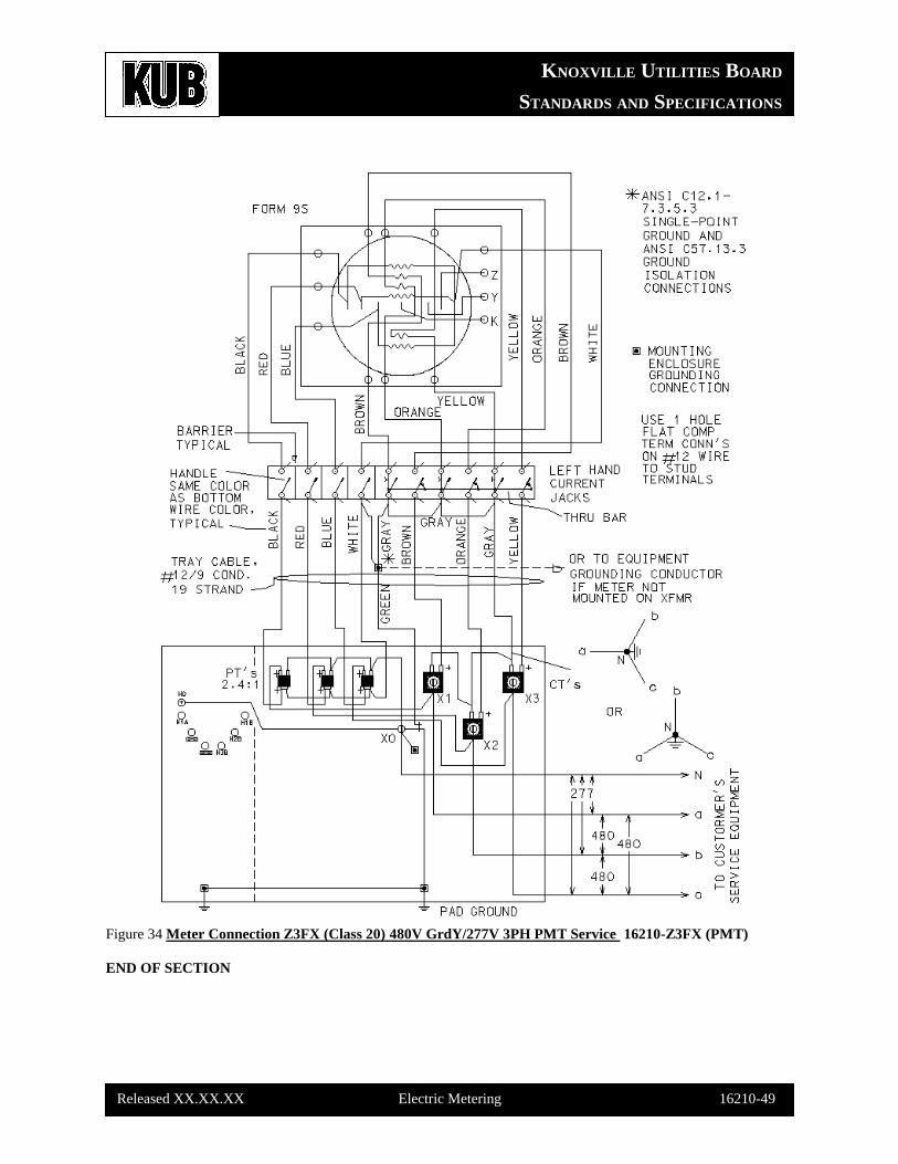
Figure 34 Meter Connection Z3FX (Class 20) 480V GrdY/277V 3PH PMT Service 16210-Z3FX (PMT)
END OF SECTION
![Knoxville daily chronicle. (Knoxville, Tenn.) 1881-09-04 [p ].€¦ · Itiiifiiirffflir VOL XII KNOXVILLE,'.'TENK: SUNDAY MORNING, SEPTEMBER 4, 1881. NO. 78 THE PRESIDENT'S REMOVAL](https://img.pdfslide.us/doc/110x75/5f95b909f653aa62e56d1a5f/knoxville-daily-chronicle-knoxville-tenn-1881-09-04-p-itiiifiiirffflir.jpg)