Embed Size (px)
Citation preview
Art Museum of Western Virginia Rainwater Harvesting System GMP-R1/Permit Application 15425-1 RMS Engineering LLC Roanoke, VA November 18, 2005 – RSA Project #0104
SECTION 15425
RAINWATER HARVESTING SYSTEM
PART 1 - GENERAL
1.1 RELATED DOCUMENTS
A. Drawings and general provisions of the Contract, including General Conditions, exhibits and related specification sections, apply to this section.
1.2 SUMMARY
A. This Specification section describes the technical specifications and general instructions for the furnishing, factory testing, handling, delivery and installation of water transfer, storage distribution and treatment equipment, pipe, valves and components related to a rain water harvesting system.
B. The Contractor is responsible for preparing the detailed engineering specifications, skid fabrication drawings and wiring diagrams necessary for fabrication, quality of materials, and quality of workmanship. This specification is intended to establish minimum acceptable standards consistent with industry practice.
C. Section Includes:
1. Storm water pumps, basin and controls,
2. Storage tank(s),
3. Strainers,
4. Distribution pumps and controls,
5. Pressure accumulator(s),
6. Filters and housings,
7. Ozone injection,
8. Water treatment automatic control systems,
9. Piping, valves and fittings,
10. Pressure regulating valves,
11. Flow meters.
D. Related Sections:
1. 15400 “Plumbing”
E. The following items are not included in this section and are included under other sections:

Art Museum of Western Virginia Rainwater Harvesting System GMP-R1/Permit Application 15425-2 RMS Engineering LLC Roanoke, VA November 18, 2005 – RSA Project #0104
1. Non-Potable water distribution piping,
2. Potable water distribution piping including water heaters,
3. Roof drainage system from roof surfaces to storm water pump basin.
1.3 REFERENCES
A. American National Standards Institute (ANSI).”
1. B16.1 “Valve Flanges,”
2. B16.5 “Pipe Flanges and Flanged Fittings,”
3. B16.18 “Cast Copper Alloy Solder Joint Pressure Fittings,”
4. B16.22 “Wrought Copper and Copper Alloy Solder Joint Pressure Fittings,”
B. American Society of Mechanical Engineers (ASME).
1. ASME Boiler and Pressure Vessel Code, Section VIII, Division 1, “Unfired Pressure Vessels.”
C. American Society for the Testing of Materials (ASTM)
1. A 536 “Ductile Iron Castings,”
2. B 32 “Solder Material,”
3. B 75 “Seamless Copper Tube,”
4. B 88 “Seamless Copper Water Tube,”
5. B 584 “Copper Alloy Sand Castings for General Applications,”
6. B 813 “Liquid and Paste Fluxes for Soldering of Copper and Copper Alloy Tube,”
7. B 828 “Standard Practice for Making Capillary Joints by Soldering of Copper and Copper Alloy Tube and Fittings,”
8. D 656 “Primers for Use in Solvent Cement Joints of Poly(Vinyl Chloride) (PVC) Plastic Pipe and Fittings”
9. D 1067 “Test Methods for Acidity or Alkalinity of Water,”
10. D 1129 “Terminology Relating to Water,”
11. D 1253 “Standard Test Method for Residual Chlorine in Water”
12. D 1293 “Test Methods for pH of Water,”
13. D 1785 “Poly(Vinyl Chloride) (PVC) Plastic Pipe, Schedules 40, 80, and 120,”

Art Museum of Western Virginia Rainwater Harvesting System GMP-R1/Permit Application 15425-3 RMS Engineering LLC Roanoke, VA November 18, 2005 – RSA Project #0104
14. D 2000 “Standard Classification System for Rubber Products in Automotive Applications,”
15. D 2564 “Solvent Cements for Poly(Vinyl Chloride) (PVC) Plastic Piping Systems,”
16. D 2855 “Practice for Making Solvent-Cemented Joints with Poly(Vinyl Chloride) (PVC) Pipe and Fittings,”
17. D 3370 “Practices for Sampling Water,”
18. E 84 “Standard Test Method for Surface Burning Characteristics of Building Materials,”
19. F 412 “Terminology Relating to Plastic Piping Systems,”
20. F 441 “Chlorinated Poly(Vinyl Chloride) (CPVC) Plastic Pipe, Schedules 40 and 80,”
21. F 1970 “Special Engineered Fittings, Appurtenances or Valves for use in Poly (Vinyl Chloride) (PVC) or Chlorinated Poly (Vinyl Chloride) (CPVC) Systems”
D. National Sanitation Foundation (NSF)
E. National Electrical Manufacturers Association (NEMA)
F. Occupational Safety and Health Act (OSHA)
G. Underwriter’s Laboratories (UL)
1.4 SYSTEM DESCRIPTION
A. The rain water harvesting system is designed to transfer, store, clarify, disinfect and treat harvested rain water to protect public health and safety, mitigate scaling and corrosion, and maintain an aesthetic appearance.
B. Harvested rain water is intended to be used for non-potable use in the building for water closets and urinals (i.e. sewage conveyance), and site landscape irrigation systems.
C. The rain water system treatment methods include:
1. Water circulation,
2. Particulate filtration,
3. Ozonation,
D. The system shall consist of packaged, modular unit treatment operations. Operation of the system shall be fully automatic.
1.5 QUALITY ASSURANCE QUALIFICATIONS
A. Equipment vendors shall have a minimum of three (3) years experience in manufacturing relevant equipment and provide references for two (2) similar facilities.
Art Museum of Western Virginia Rainwater Harvesting System GMP-R1/Permit Application 15425-4 RMS Engineering LLC Roanoke, VA November 18, 2005 – RSA Project #0104
1.6 SUBMITTALS
A. Documentation Requirements
1. Submitted documentation shall be complete and consistent to provide a written record to prove that the utilities and equipment conform to the specifications and intent of the design.
B. General
1. Submit technical specification for all equipment including treatment equipment, filters, tanks, pumps, starters, instrumentation and controls.
2. Submit electrical requirements.
3. Submit electrical data and wiring diagrams. Differentiate between factory wiring and field wiring.
4. Materials of construction and finishes of all product contact (wet) and non-contact parts.
C. Shop Drawings
1. Submit shop drawings two weeks after receipt of purchase order.
2. Submittal package shall include for all equipment (where applicable):
a. Cover letter.
b. Owner name and location.
c. Equipment name and identification number on the Drawings.
d. Purchase order number and date.
e. Manufacturer name and plant location.
f. Equipment specification including utility requirements, connection sizes and types.
g. Equipment drawings including plan and elevation, dimensions, and parts identification.
h. Equipment model, serial number, shop order number and date of fabrication.
i. Drawing title, number, revision number and date of issue.
j. Installation check procedures.
k. Pre-start-up check procedures.
l. Water quality test procedures.
Art Museum of Western Virginia Rainwater Harvesting System GMP-R1/Permit Application 15425-5 RMS Engineering LLC Roanoke, VA November 18, 2005 – RSA Project #0104
m. Equipment weights.
n. Electrical schematics with parts list.
o. Exceptions list to specification (if applicable).
p. Exceptions list to vendor specification (if applicable).
3. Cartridge and Bag Filters: Also include the following:
a. Overall dimensions and tolerances including access clearances.
b. Quantity and type of media.
c. Vessel interior coating.
d. Valve specifications including all solenoids, tubing and accessories.
e. Backwash flow rate and duration.
4. Centrifugal Pumps: Also include the following:
a. Complete performance curves showing pump rate vs. discharge pressure, impeller diameter, brake horsepower, motor horsepower, hydraulic efficiency and net-positive suction head required (NPSHR).
b. Highlighted duty point of the pump on the performance curves.
c. Detailed pump and seal drawings.
d. Overall pump dimensions, including motor and frame.
e. Size, type and location of suction and discharge connections.
f. Operating weight (lbs.).
g. Design and operating conditions.
h. Materials of construction.
i. Details of seal materials and design.
D. Closeout Submittals
1. General
a. Revise final drawings and documents to incorporate all mark-ups and notes in the shop drawings to reflect the specific installation.
b. Submit Inspection and test reports specified in "Source Quality Control" Articles in Part 2 of this Section.
2. Provide equipment documentation as follows:

Art Museum of Western Virginia Rainwater Harvesting System GMP-R1/Permit Application 15425-6 RMS Engineering LLC Roanoke, VA November 18, 2005 – RSA Project #0104
a. User manual (3 sets): Include information to install, operate, configure, calibrate, troubleshoot and service the equipment. Include final as-built drawings, parts lists and component manufacturer literature as part of the User Manual.
b. Manufacturing documentation (3 sets): Include safety and authorization certificates of vendor policies. Provide certificates of compliance for pressure vessel and piping materials, manufacturing, welding, surface treatment, inspection, testing and pressure vessel test report (Form U-1 for ASME) with a copy of the name plate. A certificate of compliance is defined as a description of design and manufacturing principles, practices, methods and equipment.
3. Centrifugal Pumps: Provide equipment documentation as follows:
a. Operating, Installation and maintenance manual.
b. Recommended spare parts for 12 month operation.
4. Instrumentation: Provide equipment documentation as follows:
a. Calibration certificates of all process instrumentation.
1.7 DELIVERY, STORAGE AND HANDLING
A. Packing/Handling
1. Prior to shipment, all openings shall be adequately sealed to protect from damage.
2. Disassemble units only to the extent to prevent damage during shipping and to facilitate field handling.
3. Pack each unit individually and include in packaging all necessary appurtenances and parts required for field installation.
4. Equipment shall be match-marked or tagged to identify location.
B. Shipping
1. Provide shipping F.O.B. job site. Pay all shipping costs.
1.8 SYSTEM START UP
A. Perform start-up services and training of operators by a factory-trained field service engineer. Provide travel and accommodation costs of factory personnel.
B. Start-up service of the system plumbing shall include the following:
1. Installation checks including utility connections.
2. System operation for routine start-up and shut-down.
3. Programming of control set points.
Art Museum of Western Virginia Rainwater Harvesting System GMP-R1/Permit Application 15425-7 RMS Engineering LLC Roanoke, VA November 18, 2005 – RSA Project #0104
4. “Off-spec” set-points and response.
5. Alarm condition and response.
6. After completion of start-up testing, obtain written sign-off of system from Owner. Correct design and fabrication deficiencies responsible for unsatisfactory test results at no cost to the Owner.
7. Conduct training of system operation and maintenance for Owner personnel.
C. Start-up of the circulation loop shall include the following:
1. System operation for routine start-up and shut-down.
2. Programming of control set points.
3. Verification of pump rotation, speed and discharge pressure.
4. During sampling period, check flow rate and velocity through distribution.
5. After completion of start-up testing, obtain written sign-off of system from Owner. Correct design and fabrication deficiencies responsible for unsatisfactory test results at no cost to the Owner.
6. Conduct training of system operation and maintenance for Owner personnel.
1.9 MAINTENANCE
A. Equipment vendor shall have an established field service organization and guarantee less than 12-hour response time, 24 hours per day, 7 days per week.
B. Provide one spare set of filter media cartridges for all filter types.
C. Provide as an option, the cost for a basic spare parts kit for an average 2 years operation.

Art Museum of Western Virginia Rainwater Harvesting System GMP-R1/Permit Application 15425-8 RMS Engineering LLC Roanoke, VA November 18, 2005 – RSA Project #0104
PART 2 - PRODUCTS
2.1 MANUFACTURERS
A. Subject to compliance with requirements and Drawing’s, provide products by one of the following:
1. Basin Access Cover
a. The BILCO Company
P.O. Box 1203 New Haven, CT 06505 Tel: 1-203-934-6363 Fax: 1-203-933-8478 Web: www.bilco.com,
b. Approved equal.
2. Rain Water Pumps,
a. Gorman-Rupp,
b. ITT Industries, Flygt,
c. Goulds,
d. Weil,
e. Approved equal.
3. Distribution Pumps and Pressure Accumulators,
a. Syncroflo, Inc.
b. Approved equal.
4. Filters
a. U.S. Filter,
b. Hayward Industrial, Inc.
c. Environmental Products Division,
d. Nemato,
e. Sta-Rite,
f. Harmsco, Inc.
5. Tanks
a. American Tank Company,

Art Museum of Western Virginia Rainwater Harvesting System GMP-R1/Permit Application 15425-9 RMS Engineering LLC Roanoke, VA November 18, 2005 – RSA Project #0104
b. American Process Technologies,
c. United States Plastic Corporation,
d. Approved equal,
6. Ozone Injection Systems
a. Ozone Solutions, Inc.
b. Ozonia
c. U.S. Filter
d. GE/Osmonics
7. Level Sensors and Monitors
a. George Fischer Signet,
b. Flowline,
c. C.W. Cox,
d. Approved equal.
8. Strainers
a. U.S. Filter/Stranco,
b. Mueller,
c. Kenloch,
d. Approved equal.
9. Pipe and Valves
a. Charlotte Pipe,
b. ASAHI,
c. Hayward Industries,
d. Spears,
e. Griffco.
10. Heat Trace
a. Chromalox Precision Heat and Control,
b. Nelson Heat Tracing Systems,
Art Museum of Western Virginia Rainwater Harvesting System GMP-R1/Permit Application 15425-10 RMS Engineering LLC Roanoke, VA November 18, 2005 – RSA Project #0104
c. Tyco Thermal Controls,
d. Approved equal.
B. Subject to compliance with requirements and Drawings, and unless specified otherwise, instruments and controls provided with standard vendor-packaged units will be considered acceptable.
2.2 GENERAL FABRICATION
A. Unless otherwise noted, all electrical enclosures shall be NEMA 4x and constructed of polycarbonate.
B. All skids shall be assembled by the vendor to allow for single field connections for power, feed, product, drain, and control air. All electrical components shall be pre-wired, neatly arranged and run in conduit. All electrical shall be wired to an electrical enclosure.
C. Provide all interconnecting wiring (power and control) between instrumentation and equipment back to main controller.
2.3 PUMP BASIN AND COVER
A. Basin
1. Pre-cast concrete structure with pipe knock-outs as specified on the Drawings.
B. Cover
1. Description: Factory assembled double-leaf counter balanced floor hatch with aluminum structural frame and stainless steel operating hardware.
2. Loading: Rated for 150 pounds per square foot with maximum allowed deflection of 0.0020 inches over entire span.
3. Covers: 1/4” (6.3 mm) aluminum diamond pattern plate.
4. Frame: 1/4” (6.3 mm) extruded aluminum with strap anchors bolted to the exterior. Perimeter neoprene door cushion.
5. Hinges: Designed for horizontal installation and bolted to the underside of covers.
6. Lifting mechanisms: Cam-action hinges shall pivot on torsion bars to provide, smooth, easy, and controlled cover operation throughout the entire arc of opening and to act as a check in retarding downward motion of the cover when closing.
7. Removable exterior turn/lift handle with a spring loaded ball detent shall be provided to open the covers.
8. Hardware:
a. Safety guard chain,
Art Museum of Western Virginia Rainwater Harvesting System GMP-R1/Permit Application 15425-11 RMS Engineering LLC Roanoke, VA November 18, 2005 – RSA Project #0104
b. Removable square key wrench,
c. Steel hold-open arm that automatically locks the cover in the open position,
d. Slam lock.
9. Finishes: Factory finish shall be mill finish aluminum with bituminous coating applied to the exterior of the frame.
10. Manufacturer and Model: Bilco Type KD-2. 48” x 48” opening.
Art Museum of Western Virginia Rainwater Harvesting System GMP-R1/Permit Application 15425-12 RMS Engineering LLC Roanoke, VA November 18, 2005 – RSA Project #0104
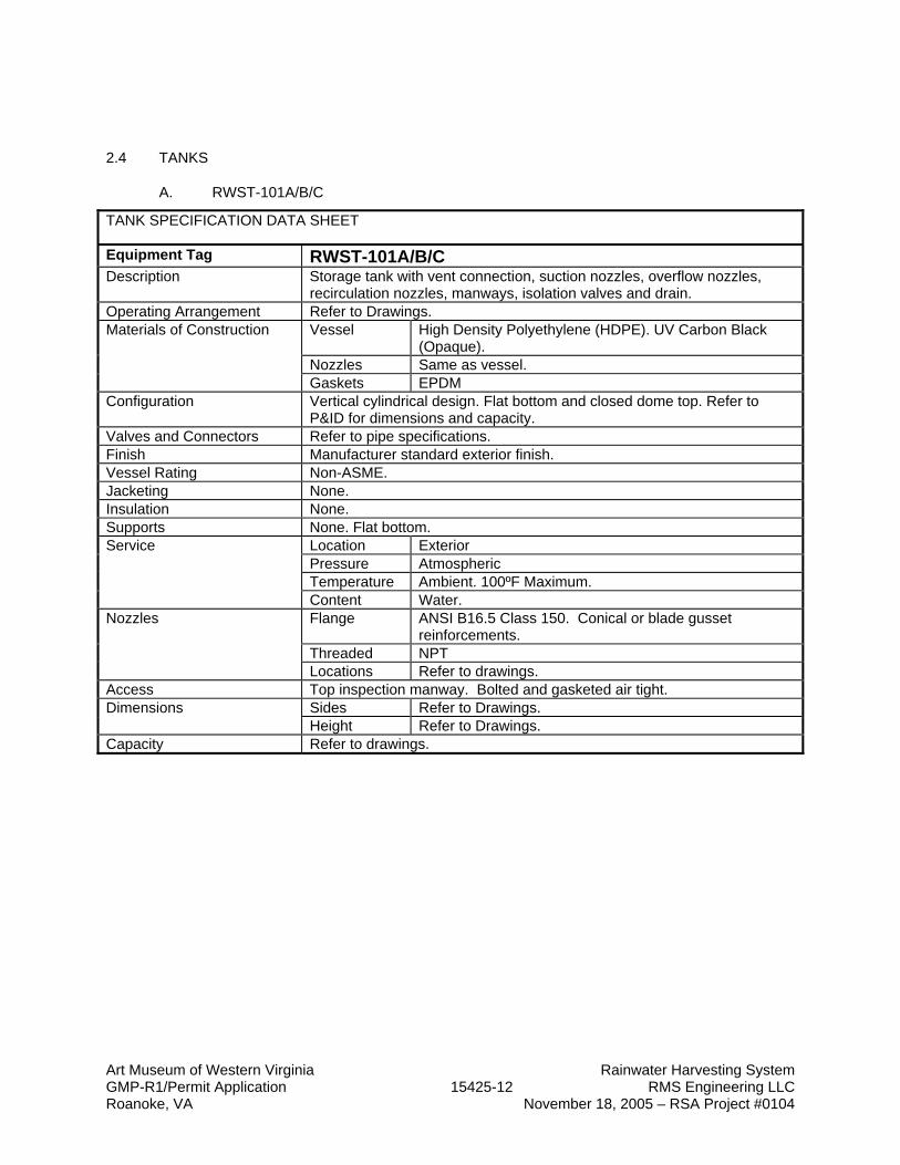
2.4 TANKS
A. RWST-101A/B/C
TANK SPECIFICATION DATA SHEET
Equipment Tag RWST-101A/B/C Description Storage tank with vent connection, suction nozzles, overflow nozzles,
recirculation nozzles, manways, isolation valves and drain. Operating Arrangement Refer to Drawings.
Vessel High Density Polyethylene (HDPE). UV Carbon Black (Opaque).
Nozzles Same as vessel.
Materials of Construction
Gaskets EPDM Configuration Vertical cylindrical design. Flat bottom and closed dome top. Refer to
P&ID for dimensions and capacity. Valves and Connectors Refer to pipe specifications. Finish Manufacturer standard exterior finish. Vessel Rating Non-ASME. Jacketing None. Insulation None. Supports None. Flat bottom.
Location Exterior Pressure Atmospheric Temperature Ambient. 100ºF Maximum.
Service
Content Water. Flange ANSI B16.5 Class 150. Conical or blade gusset
reinforcements. Threaded NPT
Nozzles
Locations Refer to drawings. Access Top inspection manway. Bolted and gasketed air tight.
Sides Refer to Drawings. Dimensions Height Refer to Drawings.
Capacity Refer to drawings.

Art Museum of Western Virginia Rainwater Harvesting System GMP-R1/Permit Application 15425-13 RMS Engineering LLC Roanoke, VA November 18, 2005 – RSA Project #0104
B. T-102
TANK SPECIFICATION DATA SHEET
Equipment Tag T-102 Description Storage tank with vent connection, bulkhead nozzles, manway, isolation
valves and drain. Operating Arrangement Refer to Drawings.
Vessel Medium or High Density Polyethylene (HDPE). UV Carbon Black (Opaque).
Nozzles Same as vessel.
Materials of Construction
Gaskets EPDM. Configuration Vertical cylindrical design. Flat bottom and closed dome top. Refer to
P&ID for dimensions and capacity. Valves and Connectors Refer to pipe specifications. Finish Manufacturer standard exterior finish. Vessel Rating Non-ASME. Jacketing None. Insulation None. Supports None. Flat bottom.
Location Interior Pressure Atmospheric Temperature Ambient. 100ºF Maximum.
Service
Content Water. Ozonated to <10.0 ppm Flange ANSI B16.5 Class 150. Conical or blade gusset
reinforcements. Threaded NPT
Nozzles
Locations Refer to drawings. Access Top inspection manway. Bolted and gasketed air tight.
Sides Refer to Drawings. Dimensions Height Refer to Drawings.
Capacity Refer to drawings.
Art Museum of Western Virginia Rainwater Harvesting System GMP-R1/Permit Application 15425-14 RMS Engineering LLC Roanoke, VA November 18, 2005 – RSA Project #0104
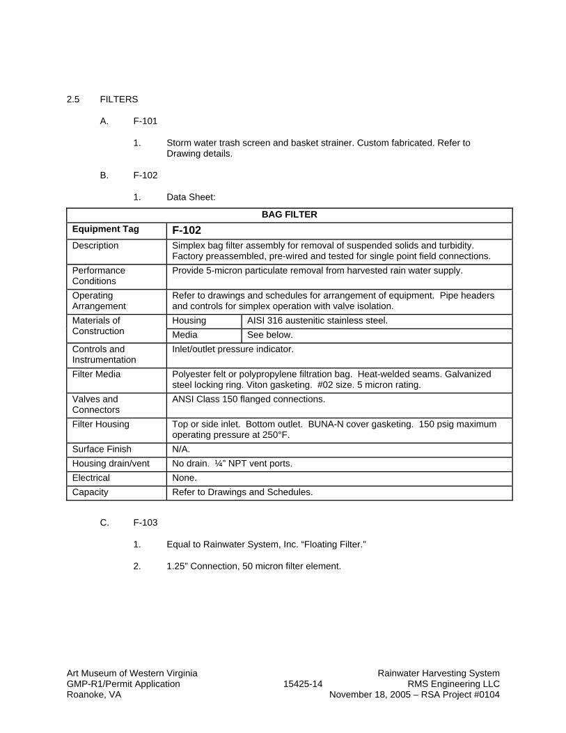
2.5 FILTERS
A. F-101
1. Storm water trash screen and basket strainer. Custom fabricated. Refer to Drawing details.
B. F-102
1. Data Sheet:
BAG FILTER Equipment Tag F-102 Description Simplex bag filter assembly for removal of suspended solids and turbidity.
Factory preassembled, pre-wired and tested for single point field connections. Performance Conditions
Provide 5-micron particulate removal from harvested rain water supply.
Operating Arrangement
Refer to drawings and schedules for arrangement of equipment. Pipe headers and controls for simplex operation with valve isolation. Housing AISI 316 austenitic stainless steel. Materials of
Construction Media See below. Controls and Instrumentation
Inlet/outlet pressure indicator.
Filter Media Polyester felt or polypropylene filtration bag. Heat-welded seams. Galvanized steel locking ring. Viton gasketing. #02 size. 5 micron rating.
Valves and Connectors
ANSI Class 150 flanged connections.
Filter Housing Top or side inlet. Bottom outlet. BUNA-N cover gasketing. 150 psig maximum operating pressure at 250°F.
Surface Finish N/A. Housing drain/vent No drain. ¼” NPT vent ports. Electrical None. Capacity Refer to Drawings and Schedules.
C. F-103
1. Equal to Rainwater System, Inc. “Floating Filter.”
2. 1.25” Connection, 50 micron filter element.

Art Museum of Western Virginia Rainwater Harvesting System GMP-R1/Permit Application 15425-15 RMS Engineering LLC Roanoke, VA November 18, 2005 – RSA Project #0104
2.6 OZONE GENERATOR AND INJECTION UNIT (OS-101)
A. Data Sheet
OZONE GENERATION AND INJECTION UNIT Equipment Tag O3-101 & O3D-101 Description Corona discharge ozone generator complete with oxygen concentrator, ozone
injection system, contact vessel, ORP sensor and off-gas ozone destruct unit. ITEM SPECIFICATION
Design Output 2.0 grams per hour production. 0.4 ppm concentration by weight.
Parent Gas Ambient air. Filtered and -100°F dewpoint. Concentrator >=90% O2 by weight. Output
Concentration Ozone Generator >=6% O3 by weight
Performance Data
Ozone Destruct >= 99% ozone reduction. Enclosures 304 Stainless Steel Oxygen Piping 304 Stainless Steel Ozone Piping Teflon tubing, 316 SS tube. Aluminum. Dielectric Ceramic, Stainless Steel. Pump 316 L Stainless Steel Injection Piping 316L Stainless Steel
Materials of Construction
Vessel 316L Stainless Steel. Enclosures NEMA 12 Stainless Steel.
Injection system shall be vendor’s standard design. Eductor Kynar venture eductor.
Injection System
Static Mixer PVC in-line mixer. MNPT end connections. Type Single-stage end-suction centrifugal. Manufacturer Per Vendor standard package. Motor TEFC or ODP.
Injection Pump
Horsepower Refer to P&ID. Manufacturer IEC, Allen-Bradley or Cutler Hammer. Enclosure NEMA 12 Location Wall or skid mounted.
Starter
Disconnect Refer to Division 16. Electrical 110 VAC, 60 Hz, 1 phase for concentrator and generator. High voltage
transformer provided with package. Compressed Air None. Cooling Water None. Air cooled. Instrumentation See “Instrumentation.” Ozone Destruct (O3D-101)
Located after vent filter on storage tank T-102. Heated catalyst bed design with blower.
Ozone Monitor Tank-mounted ozone concentration monitor (ORP sensor) shall control ozone concentration at level. See “Instrumentation.”
Ambient Ozone Monitor Cabinet mounted ozone concentration monitor shall record ambient ozone levels and provide high-level alarm. Span: 0-10 ppm. Vendor standard package.
Manufacturer and Model Equal to Ozone Solutions, Inc. Model SS-30 Ozone Injection System with OSR-4 ozone generation unit, OSR controller, desiccant air dryer, and ODS-30H off-gas ozone destruct vent.
Art Museum of Western Virginia Rainwater Harvesting System GMP-R1/Permit Application 15425-16 RMS Engineering LLC Roanoke, VA November 18, 2005 – RSA Project #0104
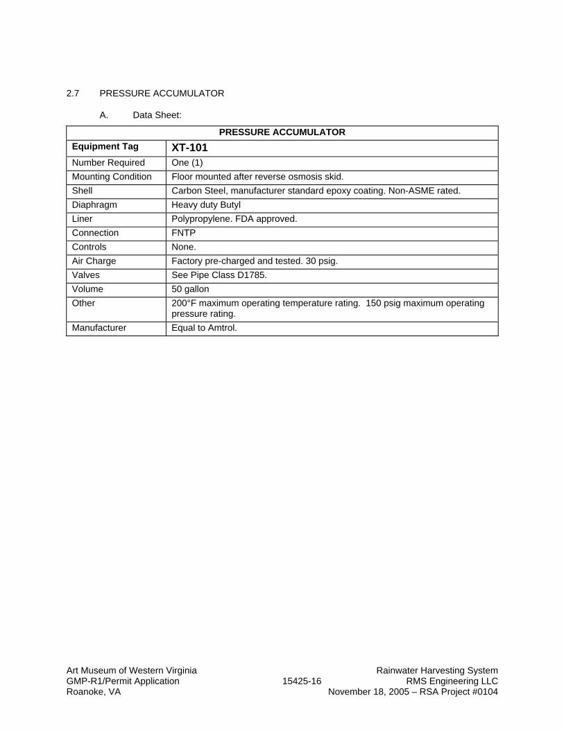
2.7 PRESSURE ACCUMULATOR
A. Data Sheet:
PRESSURE ACCUMULATOR Equipment Tag XT-101 Number Required One (1) Mounting Condition Floor mounted after reverse osmosis skid. Shell Carbon Steel, manufacturer standard epoxy coating. Non-ASME rated. Diaphragm Heavy duty Butyl Liner Polypropylene. FDA approved. Connection FNTP Controls None. Air Charge Factory pre-charged and tested. 30 psig. Valves See Pipe Class D1785. Volume 50 gallon Other 200°F maximum operating temperature rating. 150 psig maximum operating
pressure rating. Manufacturer Equal to Amtrol.
Art Museum of Western Virginia Rainwater Harvesting System GMP-R1/Permit Application 15425-17 RMS Engineering LLC Roanoke, VA November 18, 2005 – RSA Project #0104
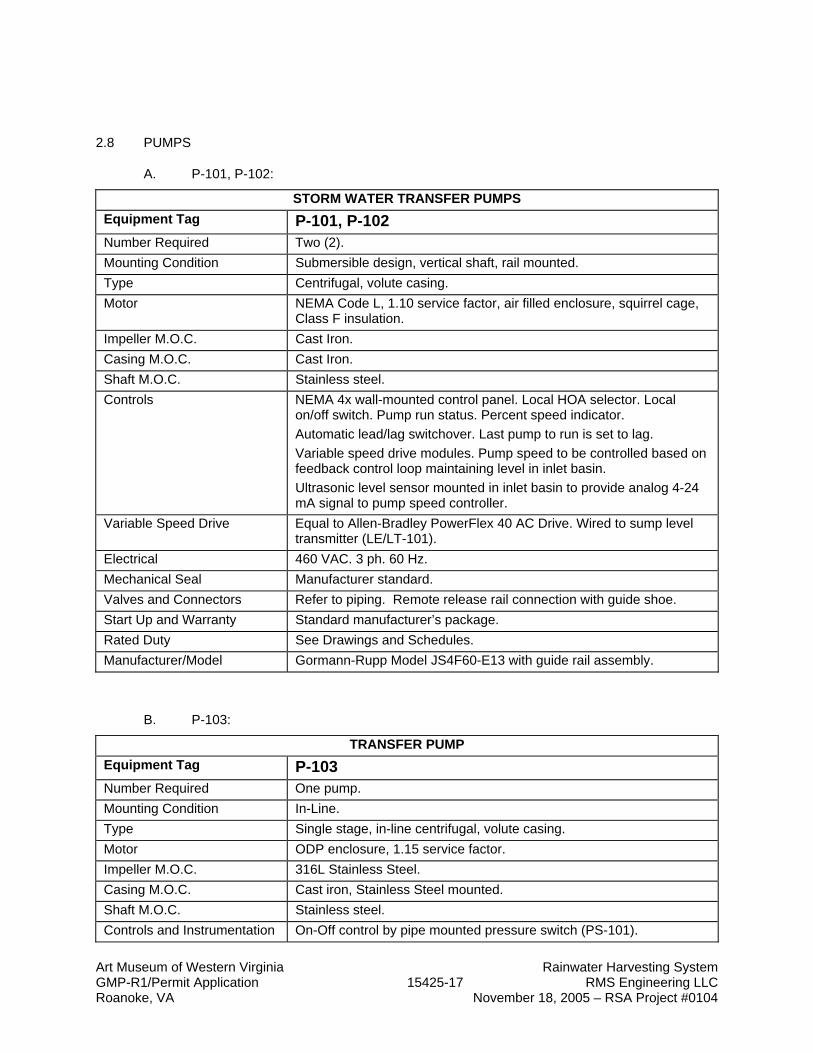
2.8 PUMPS
A. P-101, P-102:
STORM WATER TRANSFER PUMPS Equipment Tag P-101, P-102 Number Required Two (2). Mounting Condition Submersible design, vertical shaft, rail mounted. Type Centrifugal, volute casing. Motor NEMA Code L, 1.10 service factor, air filled enclosure, squirrel cage,
Class F insulation. Impeller M.O.C. Cast Iron. Casing M.O.C. Cast Iron. Shaft M.O.C. Stainless steel. Controls NEMA 4x wall-mounted control panel. Local HOA selector. Local
on/off switch. Pump run status. Percent speed indicator. Automatic lead/lag switchover. Last pump to run is set to lag. Variable speed drive modules. Pump speed to be controlled based on feedback control loop maintaining level in inlet basin. Ultrasonic level sensor mounted in inlet basin to provide analog 4-24 mA signal to pump speed controller.
Variable Speed Drive Equal to Allen-Bradley PowerFlex 40 AC Drive. Wired to sump level transmitter (LE/LT-101).
Electrical 460 VAC. 3 ph. 60 Hz. Mechanical Seal Manufacturer standard. Valves and Connectors Refer to piping. Remote release rail connection with guide shoe. Start Up and Warranty Standard manufacturer’s package. Rated Duty See Drawings and Schedules. Manufacturer/Model Gormann-Rupp Model JS4F60-E13 with guide rail assembly.
B. P-103:
TRANSFER PUMP Equipment Tag P-103 Number Required One pump. Mounting Condition In-Line. Type Single stage, in-line centrifugal, volute casing. Motor ODP enclosure, 1.15 service factor. Impeller M.O.C. 316L Stainless Steel. Casing M.O.C. Cast iron, Stainless Steel mounted. Shaft M.O.C. Stainless steel. Controls and Instrumentation On-Off control by pipe mounted pressure switch (PS-101).
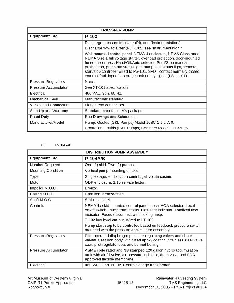
Art Museum of Western Virginia Rainwater Harvesting System GMP-R1/Permit Application 15425-18 RMS Engineering LLC Roanoke, VA November 18, 2005 – RSA Project #0104
TRANSFER PUMP Equipment Tag P-103
Discharge pressure indicator (PI), see “Instrumentation.” Discharge flow totalizer (FQI-102), see “Instrumentation.” Wall-mounted control panel. NEMA 4 enclosure, NEMA Class rated NEMA Size 1 full voltage starter, overload protection, door-mounted fused disconnect, Hand/Off/Auto selector, Start/Stop manual pushbutton, pump run status light, pump fault status light, “remote” start/stop controller wired to PS-101, SPDT contact normally closed external fault input for storage tank empty signal (LSLL-101).
Pressure Regulators None. Pressure Accumulator See XT-101 specification. Electrical 460 VAC. 3ph. 60 Hz. Mechanical Seal Manufacturer standard. Valves and Connectors Flange end connectors. Start Up and Warranty Standard manufacturer’s package. Rated Duty See Drawings and Schedules. Manufacturer/Model Pump: Goulds (G&L Pumps) Model 10SC-1-J-2-A-0.
Controller: Goulds (G&L Pumps) Centripro Model G1F33005.
C. P-104A/B:
DISTRIBUTION PUMP ASSEMBLY Equipment Tag P-104A/B Number Required One (1) skid. Two (2) pumps. Mounting Condition Vertical pump mounting on skid. Type Single stage, end suction centrifugal, volute casing. Motor ODP enclosure, 1.15 service factor. Impeller M.O.C. Bronze. Casing M.O.C. Cast iron, bronze-fitted. Shaft M.O.C. Stainless steel. Controls NEMA 4x skid-mounted control panel. Local HOA selector. Local
on/off switch. Pump “run” status. Flow rate indicator. Totalized flow indicator. Fused disconnect with locking hasp. T-102 low-level cut-out. Wired to LT-102. Pump start-stop to be controlled based on feedback pressure switch mounted with the pressure accumulator assembly.
Pressure Regulators Pilot-operated diaphragm pressure regulating valves and chack valves. Cast iron body with fused epoxy coating. Stainless steel valve seat, pilot regulator seat and bonnet bolting.
Pressure Accumulator ASME code rated and NB stamped 120 gallon hydro-accumulation tank with air fill valve, air pressure indicator, drain valve and FDA approved flexible membrane.
Electrical 460 VAC. 3ph. 60 Hz. Control voltage transformer.
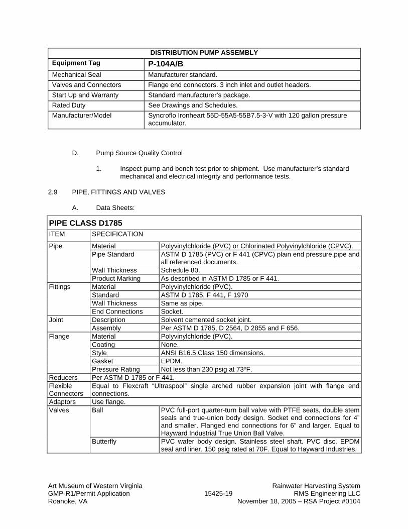
Art Museum of Western Virginia Rainwater Harvesting System GMP-R1/Permit Application 15425-19 RMS Engineering LLC Roanoke, VA November 18, 2005 – RSA Project #0104
DISTRIBUTION PUMP ASSEMBLY Equipment Tag P-104A/B Mechanical Seal Manufacturer standard. Valves and Connectors Flange end connectors. 3 inch inlet and outlet headers. Start Up and Warranty Standard manufacturer’s package. Rated Duty See Drawings and Schedules. Manufacturer/Model Syncroflo Ironheart 55D-55A5-55B7.5-3-V with 120 gallon pressure
accumulator.
D. Pump Source Quality Control
1. Inspect pump and bench test prior to shipment. Use manufacturer’s standard mechanical and electrical integrity and performance tests.
2.9 PIPE, FITTINGS AND VALVES
A. Data Sheets:
PIPE CLASS D1785 ITEM SPECIFICATION
Material Polyvinylchloride (PVC) or Chlorinated Polyvinylchloride (CPVC). Pipe Standard ASTM D 1785 (PVC) or F 441 (CPVC) plain end pressure pipe and
all referenced documents. Wall Thickness Schedule 80.
Pipe
Product Marking As described in ASTM D 1785 or F 441. Material Polyvinylchloride (PVC). Standard ASTM D 1785, F 441, F 1970 Wall Thickness Same as pipe.
Fittings
End Connections Socket. Description Solvent cemented socket joint. Joint Assembly Per ASTM D 1785, D 2564, D 2855 and F 656. Material Polyvinylchloride (PVC). Coating None. Style ANSI B16.5 Class 150 dimensions. Gasket EPDM.
Flange
Pressure Rating Not less than 230 psig at 73ºF. Reducers Per ASTM D 1785 or F 441. Flexible Connectors
Equal to Flexcraft “Ultraspool” single arched rubber expansion joint with flange end connections.
Adaptors Use flange. Ball PVC full-port quarter-turn ball valve with PTFE seats, double stem
seals and true-union body design. Socket end connections for 4” and smaller. Flanged end connections for 6” and larger. Equal to Hayward Industrial True Union Ball Valve.
Valves
Butterfly PVC wafer body design. Stainless steel shaft. PVC disc. EPDM seal and liner. 150 psig rated at 70F. Equal to Hayward Industries.

Art Museum of Western Virginia Rainwater Harvesting System GMP-R1/Permit Application 15425-20 RMS Engineering LLC Roanoke, VA November 18, 2005 – RSA Project #0104
PIPE CLASS D1785 ITEM SPECIFICATION
Check PVC full-port ball check valve with EPDM seals, and true-union body design. Socket end connections. Equal to Hayward Industries.
Strainer PVC simplex basket strainer. Flanged end connections. Equal to Hayward Industries Simplex Basket Strainer.
PIPE CLASS B88
½” to 3” 4” and Larger Pipe Seamless copper water tube, drawn
temper, Type L. ASTM B 88. See Note 1.
Seamless copper water tube, drawn temper, Type L. ASTM B 88. See Notes 2 & 5.
Fittings Wrought copper, solder-joint. ANSI/ASME B16.22
Ductile iron coupling with copper alkyd enamel paint coating, ASTM A 536. Grade “E” EPDM elastomer gasket, ASTM D 2000. Equal to Victaulic Style 606 coupling. ASTM B 75 copper alloy fittings. ASTM B 584 grooved end cast bronze fittings for 6” pipe size.
Joints ASTM B 32 solder filler material, Alloy Sb5 “95/5.” ASTM B 813 liquid or paste flux. Soldering procedures shall comply with ASTM B 828.
Rolled groove prepared and assembled in accordance with manufacturer instructions.
Mechanical Joints
Cast copper alloy unions, hexagonal stock with ball-and-socket joint, solder joint ends. ANSI/ASME B16.18.
ANSI Class 150 flange adapter equal to Victaulic Style 641 for connections to flanged equipment. ANSI/ASME B16.5 dimensions.
Valves Gate Use ball valve. Use ball valve. Ball All bronze, 2 piece, reduced port,
PTFE seats, solder end connections. 400 psig min WOG. Apollo 32-100, Milwaukee BA-150, Watts B-6001.
Class 125, cast iron body, epoxy coated. Full port, flanged ends, stainless steel ball and stem. ANSI B16.1 flange dimensions. Watts G-4000-FDA series.
Check Bronze body and clapper, solder ends, 200 WOG. Watts B-5001, Milwaukee 1509, Stockham B-309.
Iron body, bronze mounted, flanged ends, 200 WOG. Watts 411, Milwaukee F-2974-M, Stockham G-931.
Balancing All bronze, 2 piece, RPTFE seats, solder end connections. 600 psig WOG. Apollo 70-100, Milwaukee BA-150, Watts B-6001. CamLock handle.
Cast iron lug body butterfly valve. Bronze disc, replaceable EPT liner, stainless steel stem, 200 psig CWP.
Drain All bronze, 2 piece, RPTFE seats, thread x solder end connections. 600 psig WOG. Apollo 70-100, Milwaukee BA-150, Watts B-6001. Hose thread adapter with cap and chain.
Notes: 1. Below grade water piping 3” and smaller shall be Type K copper with bituminous coating and copper
brazed joints, BCuP filler alloy. ANSI/AWS A5.8. Procedures shall be per ANSI/AWS B2.2. 2. Below grade water piping 4” and larger shall be ductile iron cement lined Class 52 piping with push-
on joints.

Art Museum of Western Virginia Rainwater Harvesting System GMP-R1/Permit Application 15425-21 RMS Engineering LLC Roanoke, VA November 18, 2005 – RSA Project #0104
3. Contact between dissimilar metals shall be made with di-electric couplings or di-electric flanges. Contact between ferrous stud bolts and bronze flanges shall be electrically insulated with non-metallic washers.
4. Provide mechanical joint connections to all equipment such as water heaters, pumps, compressors, etc.

Art Museum of Western Virginia Rainwater Harvesting System GMP-R1/Permit Application 15425-22 RMS Engineering LLC Roanoke, VA November 18, 2005 – RSA Project #0104
2.10 INSTRUMENTATION
A. Data Sheet:
INSTRUMENTATION Pressure Indicators (PI-XXX) Equal to Ashcroft Model 1005P analog, bourdon tube pressure
indicator. ABS casing. Polycarbonate window. ¼” process connection with ¼” isolation valve. 0-200 psig range.
Pressure Switch (PS-101) Equal to Ashcroft Model APA brass body, single setpoint, field adjustable. 120 VAC. BUNA-N seals. ¼” NPT process connection. 15 psi nominal range.
Flow Meter (FQI-101 & 102) Equal to Neptune Model T-10 turbine meter. Bronze body construction. 2” NPT end connections (FQI-101), 1” NPT end connection (FQI-102). 100 gallon per sweep registration. Bronze register cover.
Level Sensors (LE/LT/LIC-101 & 102)
Equal to Flowline Model LU20-5001 ultrasonic level transmitter. 2” NPT threaded connection to PVC dip tube. Model LI14-1001 panel mounted level indicator with four (4) relays and 4-20mA analog signal.
Level Switch (LS-101) Equal to Flowline Model LZ10-1405-50’ tuning fork level switch. 50 foot cable. ¾” NPT threaded connection to level standpipe at tank low level elevation.
Control Valve (XV-101, XY-101) Hayward Industries Series EA electrically actuated ball valve. NEMA 4x actuator enclosure. 110 VAC. True union end connections. Hayward Series LS electric actuator control station with Off/Local/Remote selector switch for remote wiring to LIC-102.
Dissolved Ozone Monitor Mounted on O3-101 skid. Equal Ozone Solutions MOZ-44P. 0.001 – 1.999 ppm range. 1 ppb resolution. Accuracy +/- 0.5% over range. Hysteresis 0.1 ppm. 2 Watts @ 120 VAC. 4-20 mA output. Two (2) SPDT relays. ORP Flow cell with 12 foot cable.
2.11 HEAT TRACE CABLE AND CONTROL
A. Heat trace cable shall be self-regulating freeze protection tape equal to Chromalox Model SRF heating cable.
B. Control shall be provided by Chromalox Model FPASM WeatherTrace panel, NEMA 4X enclosure, with external ambient sensing control.

Art Museum of Western Virginia Rainwater Harvesting System GMP-R1/Permit Application 15425-23 RMS Engineering LLC Roanoke, VA November 18, 2005 – RSA Project #0104
PART 3 - EXECUTION
3.1 EXAMINATION
A. Floor Hatch
1. Verify that the vault access door installation will not disrupt other trades. Verify that the substrate is dry, clean, and free of foreign matter. Report and correct defects prior to any installation.
B. Examine product data for connection sizes and dimensional requirements prior to installation of rough plumbing.
C. Examine rough plumbing to verify proper interface prior to installation of equipment.
D. Examine product data for requirements of concrete base dimensions.
3.2 INSTALLATION
A. Floor Hatch
1. Check as-built conditions and verify the manufacturer’s vault access door details for accuracy to fit the application prior to fabrication. Comply with the vault access door manufacturer’s installation instructions.
2. Furnish mechanical fasteners consistent with the vault access door manufacturer’s instructions.
B. Install skidded components and other equipment in accordance with manufacturers’ written instructions and recommendations.
C. Install equipment on concrete bases. Set and connect units and major accessories according to manufacturers' written instructions. Install units plumb, level, and firmly anchored in locations indicated. Maintain manufacturers' recommended clearances. Orient equipment, controls, and devices needing service for proper accessibility.
D. Install piping and valves in accordance with the instructions included under the respective Pipe Class.
E. Affix instrument identification numbers, date of calibration, and next date of calibration. Labels shall be clearly visible.
F. Tag all equipment, valves, and instruments with permanent stainless steel tags bearing Drawings tag number.
3.3 CONNECTIONS
A. Install piping next to equipment and accessories to allow service and maintenance.
B. Connect piping to equipment and accessories with flanges, unions, and couplings as shown on Drawings and as specified under the respective pipe class.

Art Museum of Western Virginia Rainwater Harvesting System GMP-R1/Permit Application 15425-24 RMS Engineering LLC Roanoke, VA November 18, 2005 – RSA Project #0104
C. Install piping for waste and reject streams. Pipe liquid waste drains to sanitary drainage systems. Provide air gaps at indirect waste drains with not less than 3 pipe diameters between the waste discharge and the floor drain’s flood rim.
D. Ground electrical equipment.
E. Tighten electrical connectors and terminals according to manufacturer's published torque-tightening values. Where manufacturer's torque values are not indicated, use those specified in UL 486A and UL 486B.
F. Arrange for electric-power connections to equipment that requires power. Electric power, wiring, and disconnect switches are specified in Division 16 Sections.
3.4 FIELD QUALITY CONTROL
A.
3.5 SEQUENCE OF OPERATION
A. General
1. The purpose of the rain water harvesting system is to provide filtered rain water under pressure to building non-potable water uses.
2. Ozonated water is drawn from storage tank T-102 by the system booster pump (P-104A/B) to provide non-potable water for flushing toilets.
3. As T-102 level draws down, automatic valve XV-102 shall open to make up water to the tank.
4. Ozone injection system is provided to dissolve gaseous ozone (O3) into the water for microbial control, clarification, and odor mitigation.
5. Transfer pump P-103 provides system pressure up to the ozone injection system through particulate filter F-102. This pump also provides non-ozonated water to the building irrigation system.
B. Rain Water Pumps (P-101, P-102):
1. P-101 and P-102 are submersible centrifugal pumps that lift rain water from the rain water catchment basin to storage tanks RWST-101A/B/C.
2. Pump start / stop and speed control is provided by a continuous level sensor and transmitter (LE/LT-101) located in the catchment basin. The LT-101 output is a 4-20mA analog signal fed to the pump variable speed control system.
3. When LE/LT-101 indicates 50% full level, the lead pump shall start at minimum speed.
4. Pump speed shall be directly proportional to sump level. At 100% sump level, pump speed shall be 100% rated speed.
5. If lead pump maximum speed is reached and sump level continues to rise, then the lag pump shall start at minimum speed. Lag pump speed shall increase to

Art Museum of Western Virginia Rainwater Harvesting System GMP-R1/Permit Application 15425-25 RMS Engineering LLC Roanoke, VA November 18, 2005 – RSA Project #0104
match sump level. The lead and lag pumps shall continue to run until 10% sump level is reached, then the pumps shall stop.
6. If both pumps are running at maximum speed and level does not drop, then both pumps shall continue to run and water shall spill to the overflow drain pipe. No alarm is required.
7. The last pump to start shall be reset as the lag pump.
C. Transfer Pump (P-103):
1. Transfer pump P-103 is an in-line centrifugal pump controlled by it’s own panel. The panel provides “Local, Off, Auto” mode selection with a manual start/stop pushbutton.
2. Automatic start/stop control is provided by pressure switch PS-101 high and low pressure settings.
3. Level switch LS-101 shall prevent automatic start of P-103 when tanks T-101A,B,C are empty.
D. Booster Pump (P-104A/B):
1. This booster pump shall start and stop based on the factory mounted pressure switch to maintain distribution system pressure.
2. Low level alarm (LAL-102) from T-102 shall send a signal to the booster pump set to prevent pumps from starting (low level safety interlock).
E. Treatment Skid
1. The ozone injection system shall operate automatically by it’s own control systems.
2. Ozone injection concentration shall be set at 2.0 ppm.
3.6 DEMONSTRATION
A. Engage a factory-authorized service representative to perform startup services and to demonstrate and train Owner's maintenance personnel as specified below.
1. Train Owner's maintenance personnel on procedures and schedules related to start up and shutdown, troubleshooting, servicing, and preventive maintenance.
2. Review data in the operation and maintenance manuals.
3. Review data in the operation and maintenance manuals.
4. Schedule training with Owner with at least 7 days' advance notice.
3.7 PROTECTION
A. The Contractor is fully responsible for providing adequate protection to piping and components during construction and start-up.

Art Museum of Western Virginia Rainwater Harvesting System GMP-R1/Permit Application 15425-26 RMS Engineering LLC Roanoke, VA November 18, 2005 – RSA Project #0104
B. Comply with manufacturer’s written instructions for equipment protection.
END OF SECTION