Embed Size (px)
Citation preview
Ontario Guidelines for Residential Rainwater Harvesting Systems
2010

Page | i
Ontario Guidelines for Residential Rainwater Harvesting Systems
2010
In Ontario, Ontario‘s Building Code (OBC) and the Ontario Electrical Safety Code are the codes
that are applicable to the design, construction and management of rainwater harvesting systems.
This guidelines document and the accompanying handbook provide guidance for designing,
constructing, and managing rainwater harvesting systems based on the minimum safety
requirements established in these codes:
Ontario‘s Building Code:
http://www.e-laws.gov.on.ca/html/regs/english/elaws_regs_060350_e.htm
Ontario Electrical Safety Code Regulation:
http://www.e-laws.gov.on.ca/html/regs/english/elaws_regs_990164_e.htm
This document is not intended to convey legal advice and is not a substitute for professional
technical design. While care has been taken to ensure accuracy, the examples and explanations in
this guide are given for the purposes of illustration only.
Readers must refer to the actual wording of the applicable law, including the Building Code Act,
1992, O. Reg. 350/06 (the Building Code), O. Reg. 164/99 (the Ontario Electrical Safety Code)
and other applicable law. Persons seeking legal advice about the matters discussed in these
guidelines should consult a solicitor.
The Author and Editors do not assume responsibility for errors or oversights resulting from the
information contained herein.
© Copyright
All rights reserved. No part of this book may be used or reproduced in any form
or by any means, without prior written permission of the Author or Editors.
First Edition, December 2010

Page | ii
Acknowledgements
Rainwater Harvesting Task Group
The Ontario Guidelines for Residential Rainwater Harvesting Systems 2010 were developed
with assistance from a Rainwater Harvesting Task Group made up of government and industry
stakeholders. Task Group members represent the following stakeholder groups:
1. Alberta Municipal Affairs
2. Canada Mortgage and Housing Corporation
3. Canadian Water and Wastewater Association
4. City of Calgary
5. City of Guelph
6. Ecoshift
7. Evolve Builders Group Inc.
8. GE Water & Process Technologies
9. Interpump Supply Ltd.
10. Ontario Ministry of Municipal Affairs and Housing
11. Region of Durham
12. RH2O North America Inc.
13. Toronto and Region Conservation Authority
Task Group Members
Tyler Wightman
Alf Durnie
Sidney Manning
Pierre McDonald
Cate Soroczan
T. Duncan Ellison
Liliana Bozic
Wayne Galliher
David Auliffe
Geoff Jones
Ben Polley
Mark Myronyk
Peter Follett
Shane Gallagher
Danny Hui
Glen Pleasance
Scott Robinson
Tim Van Seters
Author
Christopher Despins, M.Sc., P.Eng.
President
Connect the Drops
Editors
Chantelle Leidl, M.Sc. Khosrow Farahbakhsh, Ph.D., P.Eng.
Rainwater Harvesting Specialist Associate Professor
University of Guelph
Page | iii
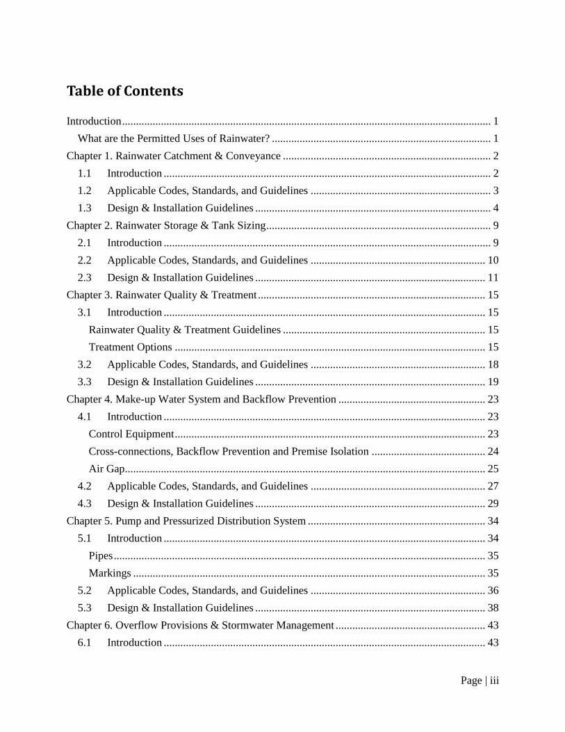
Table of Contents
Introduction ..................................................................................................................................... 1
What are the Permitted Uses of Rainwater? ............................................................................... 1
Chapter 1. Rainwater Catchment & Conveyance ........................................................................... 2
1.1 Introduction ...................................................................................................................... 2
1.2 Applicable Codes, Standards, and Guidelines ................................................................. 3
1.3 Design & Installation Guidelines ..................................................................................... 4
Chapter 2. Rainwater Storage & Tank Sizing ................................................................................. 9
2.1 Introduction ...................................................................................................................... 9
2.2 Applicable Codes, Standards, and Guidelines ............................................................... 10
2.3 Design & Installation Guidelines ................................................................................... 11
Chapter 3. Rainwater Quality & Treatment .................................................................................. 15
3.1 Introduction .................................................................................................................... 15
Rainwater Quality & Treatment Guidelines ......................................................................... 15
Treatment Options ................................................................................................................ 15
3.2 Applicable Codes, Standards, and Guidelines ............................................................... 18
3.3 Design & Installation Guidelines ................................................................................... 19
Chapter 4. Make-up Water System and Backflow Prevention ..................................................... 23
4.1 Introduction .................................................................................................................... 23
Control Equipment ................................................................................................................ 23
Cross-connections, Backflow Prevention and Premise Isolation ......................................... 24
Air Gap.................................................................................................................................. 25
4.2 Applicable Codes, Standards, and Guidelines ............................................................... 27
4.3 Design & Installation Guidelines ................................................................................... 29
Chapter 5. Pump and Pressurized Distribution System ................................................................ 34
5.1 Introduction .................................................................................................................... 34
Pipes ...................................................................................................................................... 35
Markings ............................................................................................................................... 35
5.2 Applicable Codes, Standards, and Guidelines ............................................................... 36
5.3 Design & Installation Guidelines ................................................................................... 38
Chapter 6. Overflow Provisions & Stormwater Management ...................................................... 43
6.1 Introduction .................................................................................................................... 43
Page | iv
Rainwater Harvesting for Stormwater Detention & Retention ............................................. 45
6.2 Applicable Codes, Standards, and Guidelines ............................................................... 46
6.3 Design & Installation Guidelines ................................................................................... 47
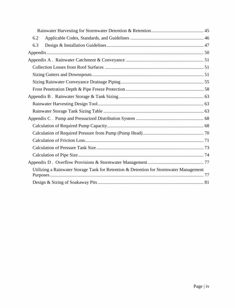
Appendix ....................................................................................................................................... 50
Appendix A . Rainwater Catchment & Conveyance ................................................................... 51
Collection Losses from Roof Surfaces ..................................................................................... 51
Sizing Gutters and Downspouts ................................................................................................ 51
Sizing Rainwater Conveyance Drainage Piping ....................................................................... 55
Frost Penetration Depth & Pipe Freeze Protection ................................................................... 58
Appendix B . Rainwater Storage & Tank Sizing ......................................................................... 63
Rainwater Harvesting Design Tool ........................................................................................... 63
Rainwater Storage Tank Sizing Table ...................................................................................... 63
Appendix C . Pump and Pressurized Distribution System .......................................................... 68
Calculation of Required Pump Capacity................................................................................... 68
Calculation of Required Pressure from Pump (Pump Head) .................................................... 70
Calculation of Friction Loss...................................................................................................... 71
Calculation of Pressure Tank Size ............................................................................................ 73
Calculation of Pipe Size ............................................................................................................ 74
Appendix D . Overflow Provisions & Stormwater Management ................................................ 77
Utilizing a Rainwater Storage Tank for Retention & Detention for Stormwater Management
Purposes .................................................................................................................................... 77
Design & Sizing of Soakaway Pits ........................................................................................... 81

Page | 1
Introduction
Rainwater harvesting (RWH) is the ancient practice of collecting rainwater and storing it for later
use. RWH systems are comprised of a roof catchment, conveyance network, rainwater storage
tank, pump, and fixtures where rainwater is utilized. Most systems also incorporate treatment
technologies to improve the quality of rainwater before and/or after storage, and include
provisions for periods of insufficient rainfall (a water make-up supply) and times of excessive
rainfall (overflow provisions).
The most important consideration when designing and installing a RWH system are the pertinent
provincial codes and regulations, standards, and municipal bylaws. Other considerations include
how the design, installation and management of RWH systems can affect the quantity of water
saved and the quality of rainwater harvested, as well as cold weather suitability of the system.
The design and installation guidelines are presented in several sections, organized by the
different components of RWH systems. These components are as follows:
1. Rainwater Catchment & Conveyance
2. Rainwater Storage & Tank Sizing
3. Rainwater Quality & Treatment
4. Water Make-up System & Backflow Prevention
5. Pump & Pressurized Distribution System
6. Overflow Provisions & Stormwater Management
This document is aimed at individuals with knowledge of the building sector and the basic trades
involved in rainwater harvesting (i.e., plumbing, electrical, and site service work). Relevant
clauses from existing codes and regulations, standards, and guidelines are presented, as well as
additional design criteria derived from recent field experience and international best practices for
rainwater harvesting. An accompanying document, Ontario Guidelines for Residential
Rainwater Harvesting Systems Handbook – 2010, provides additional background, explanation
and instruction for each item discussed here. Both documents are primarily focused on
residential rainwater harvesting systems designed for non-potable use.
What are the Permitted Uses of Rainwater?
As of the publication date of these Guidelines (July 2010) applicable provincial codes and
regulations in the Province of Ontario permit the use of rainwater for flushing toilets and urinals,
as well as for sub-surface irrigation and below ground irrigation systems1.
1 Rainwater connections must be made in accordance with Ontario‘s Building Code. 2006. Ministry of Municipal
Affairs and Housing, Toronto, ON., and in accordance with local authorities.
Page | 2
Chapter 1. Rainwater Catchment & Conveyance
1.1 Introduction
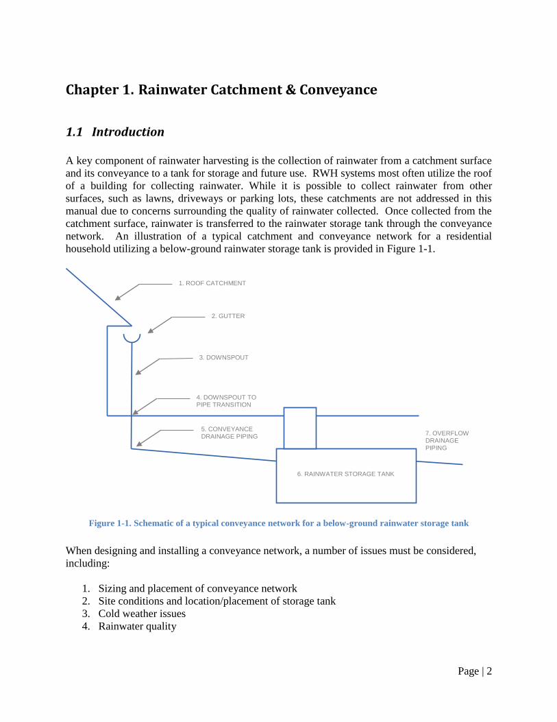
A key component of rainwater harvesting is the collection of rainwater from a catchment surface
and its conveyance to a tank for storage and future use. RWH systems most often utilize the roof
of a building for collecting rainwater. While it is possible to collect rainwater from other
surfaces, such as lawns, driveways or parking lots, these catchments are not addressed in this
manual due to concerns surrounding the quality of rainwater collected. Once collected from the
catchment surface, rainwater is transferred to the rainwater storage tank through the conveyance
network. An illustration of a typical catchment and conveyance network for a residential
household utilizing a below-ground rainwater storage tank is provided in Figure 1-1.
Figure 1-1. Schematic of a typical conveyance network for a below-ground rainwater storage tank
When designing and installing a conveyance network, a number of issues must be considered,
including:
1. Sizing and placement of conveyance network
2. Site conditions and location/placement of storage tank
3. Cold weather issues
4. Rainwater quality
1. ROOF CATCHMENT
2. GUTTER
3. DOWNSPOUT
4. DOWNSPOUT TO PIPE TRANSITION
6. RAINWATER STORAGE TANK
5. CONVEYANCE DRAINAGE PIPING
7. OVERFLOW DRAINAGE PIPING
Page | 3
1.2 Applicable Codes, Standards, and Guidelines
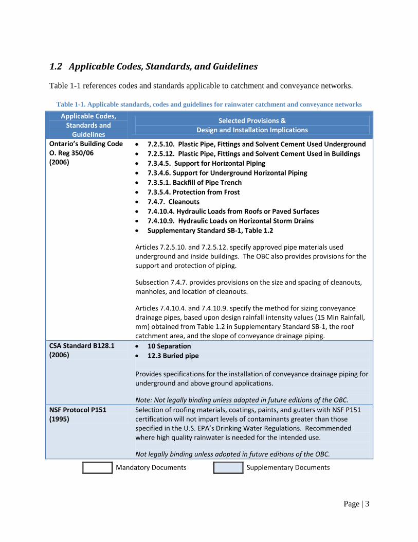
Table 1-1 references codes and standards applicable to catchment and conveyance networks.
Table 1-1. Applicable standards, codes and guidelines for rainwater catchment and conveyance networks
Applicable Codes, Standards and
Guidelines
Selected Provisions & Design and Installation Implications
Ontario’s Building Code O. Reg 350/06 (2006)
7.2.5.10. Plastic Pipe, Fittings and Solvent Cement Used Underground
7.2.5.12. Plastic Pipe, Fittings and Solvent Cement Used in Buildings
7.3.4.5. Support for Horizontal Piping
7.3.4.6. Support for Underground Horizontal Piping
7.3.5.1. Backfill of Pipe Trench
7.3.5.4. Protection from Frost
7.4.7. Cleanouts
7.4.10.4. Hydraulic Loads from Roofs or Paved Surfaces
7.4.10.9. Hydraulic Loads on Horizontal Storm Drains
Supplementary Standard SB-1, Table 1.2
Articles 7.2.5.10. and 7.2.5.12. specify approved pipe materials used underground and inside buildings. The OBC also provides provisions for the support and protection of piping.
Subsection 7.4.7. provides provisions on the size and spacing of cleanouts, manholes, and location of cleanouts.
Articles 7.4.10.4. and 7.4.10.9. specify the method for sizing conveyance drainage pipes, based upon design rainfall intensity values (15 Min Rainfall, mm) obtained from Table 1.2 in Supplementary Standard SB-1, the roof catchment area, and the slope of conveyance drainage piping.
CSA Standard B128.1 (2006)
10 Separation
12.3 Buried pipe Provides specifications for the installation of conveyance drainage piping for underground and above ground applications.
Note: Not legally binding unless adopted in future editions of the OBC.
NSF Protocol P151 (1995)
Selection of roofing materials, coatings, paints, and gutters with NSF P151 certification will not impart levels of contaminants greater than those specified in the U.S. EPA’s Drinking Water Regulations. Recommended where high quality rainwater is needed for the intended use.
Not legally binding unless adopted in future editions of the OBC.
Mandatory Documents Supplementary Documents
Page | 4
1.3 Design & Installation Guidelines
Design and installation guidelines: Note: refer to Section 1.2 Applicable Codes, Standards, and Guidelines for the specific provisions
that apply when the term ―in accordance with applicable provincial codes and regulations‖ is used.
1. When selecting the catchment(s) for collecting rainwater:
a. Only roof surfaces are recommended;
b. Collection from green roofs is not recommended;
c. Avoid sections of the roof with overhanging foliage, or trim where possible;
d. If rainwater collected from the catchment surface must be of very high quality,
materials with NSF P151 certification can be selected.
2. To maximize the volume of rainwater collected by the RWH system:
a. The catchment surface should be as large as possible;
b. If a roof catchment material is to be selected and installed in conjunction with the
RWH system, material with minimal collection losses, such as steel, should be
selected (refer to Table A-1 for details);
c. Convey rainwater using appropriately sized and sloped components, including
gutters, downspouts, and/or conveyance drainage piping; and
d. Where possible, multiple roof catchments can be connected to a central or
‗communal‘ rainwater storage tank.
3. Gutters and downspouts:
a. Gutter and downspout material:
i. Aluminum or galvanized steel are recommended,
ii. Copper, wood, vinyl, and plastic gutter and downspout materials are not
recommended,
iii. If rainwater conveyed through gutters and downspouts must be of very
high quality, materials with NSF P151 certification can be selected.
b. Gutter slope:
i. Where possible, slope gutters in the direction of the location of the
rainwater storage tank,
ii. Ensure a minimum slope of 0.5-2% (the greater the slope the better) is
maintained throughout the gutter length.
c. Gutter size:
i. In general, 125 mm [5 in.] K-style gutter is commonly used and should be
suitable for most typical residential roof drainage areas and gutter lengths;
ii. To determine the size of gutter required for a given roof drainage area:
1. Consult the applicable provincial codes and regulations pertaining
to the design rainfall intensity for the site location,
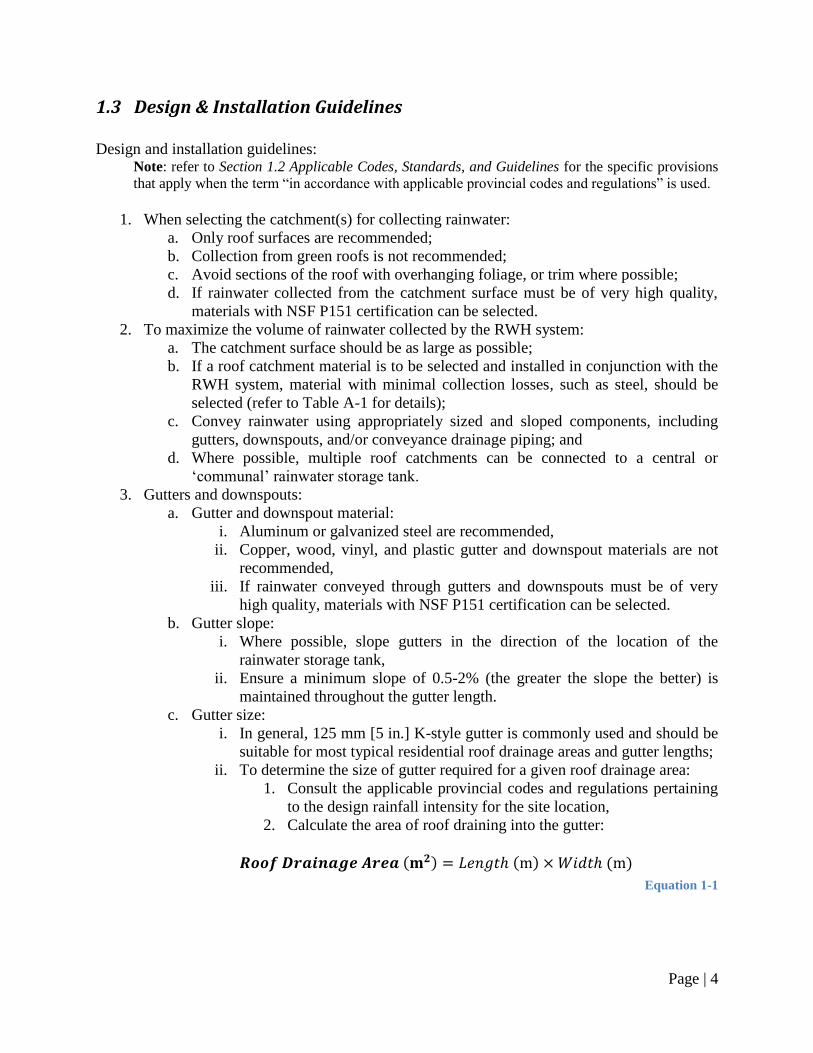
2. Calculate the area of roof draining into the gutter:
( ) ( ) ( )
Equation 1-1
Page | 5
Where: Length = length of the gutter served by a downspout (m)
Width = distance from the eave to the ridge of the roof
drainage area served (m)
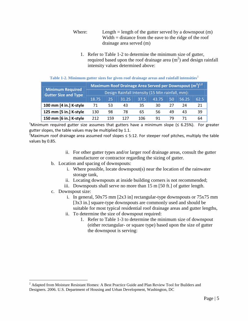
1. Refer to Table 1-2 to determine the minimum size of gutter,
required based upon the roof drainage area (m2) and design rainfall
intensity values determined above:
Table 1-2. Minimum gutter sizes for given roof drainage areas and rainfall intensities2
Minimum Required Gutter Size and Type
Maximum Roof Drainage Area Served per Downspout (m2)1,2
Design Rainfall Intensity (15 Min rainfall, mm):
18.75 25 31.25 37.5 43.75 50 56.25 62.5
100 mm [4 in.] K-style 71 53 43 35 30 27 24 21
125 mm [5 in.] K-style 130 98 78 65 56 49 43 39
150 mm [6 in.] K-style 212 159 127 106 91 79 71 64 1Minimum required gutter size assumes that gutters have a minimum slope (≤ 6.25%). For greater gutter slopes, the table values may be multiplied by 1.1. 2Maximum roof drainage area assumed roof slopes ≤ 5:12. For steeper roof pitches, multiply the table values by 0.85.
ii. For other gutter types and/or larger roof drainage areas, consult the gutter
manufacturer or contractor regarding the sizing of gutter.
b. Location and spacing of downspouts:
i. Where possible, locate downspout(s) near the location of the rainwater
storage tank,
ii. Locating downspouts at inside building corners is not recommended;
iii. Downspouts shall serve no more than 15 m [50 ft.] of gutter length.
c. Downspout size:
i. In general, 50x75 mm [2x3 in] rectangular-type downspouts or 75x75 mm
[3x3 in.] square-type downspouts are commonly used and should be
suitable for most typical residential roof drainage areas and gutter lengths,
ii. To determine the size of downspout required:
1. Refer to Table 1-3 to determine the minimum size of downspout
(either rectangular- or square type) based upon the size of gutter
the downspout is serving:
2 Adapted from Moisture Resistant Homes: A Best Practice Guide and Plan Review Tool for Builders and
Designers. 2006. U.S. Department of Housing and Urban Development, Washington, DC
Page | 6
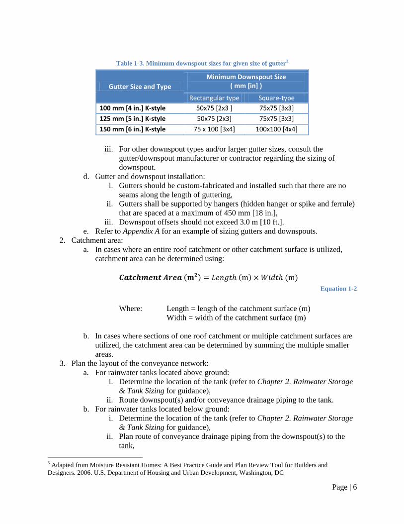
Table 1-3. Minimum downspout sizes for given size of gutter3
Gutter Size and Type Minimum Downspout Size
( mm [in] )
Rectangular type Square-type
100 mm [4 in.] K-style 50x75 [2x3 ] 75x75 [3x3]
125 mm [5 in.] K-style 50x75 [2x3] 75x75 [3x3]
150 mm [6 in.] K-style 75 x 100 [3x4] 100x100 [4x4]
iii. For other downspout types and/or larger gutter sizes, consult the
gutter/downspout manufacturer or contractor regarding the sizing of
downspout.
d. Gutter and downspout installation:
i. Gutters should be custom-fabricated and installed such that there are no
seams along the length of guttering,
ii. Gutters shall be supported by hangers (hidden hanger or spike and ferrule)
that are spaced at a maximum of 450 mm [18 in.],
iii. Downspout offsets should not exceed 3.0 m [10 ft.].
e. Refer to Appendix A for an example of sizing gutters and downspouts.
2. Catchment area:
a. In cases where an entire roof catchment or other catchment surface is utilized,
catchment area can be determined using:
( ) ( ) ( )
Equation 1-2
Where: Length = length of the catchment surface (m)
Width = width of the catchment surface (m)
b. In cases where sections of one roof catchment or multiple catchment surfaces are
utilized, the catchment area can be determined by summing the multiple smaller
areas.
3. Plan the layout of the conveyance network:
a. For rainwater tanks located above ground:
i. Determine the location of the tank (refer to Chapter 2. Rainwater Storage
& Tank Sizing for guidance),
ii. Route downspout(s) and/or conveyance drainage piping to the tank.
b. For rainwater tanks located below ground:
i. Determine the location of the tank (refer to Chapter 2. Rainwater Storage
& Tank Sizing for guidance),
ii. Plan route of conveyance drainage piping from the downspout(s) to the
tank,
3 Adapted from Moisture Resistant Homes: A Best Practice Guide and Plan Review Tool for Builders and
Designers. 2006. U.S. Department of Housing and Urban Development, Washington, DC
Page | 7
iii. Ensure that there are no buried service lines (gas, electricity, water,
stormwater, wastewater, phone, or cable lines) in the area where digging
will take place to accommodate the buried conveyance drainage pipes by
contacting the municipality and service providers,
iv. For additional guidance on planning the layout of conveyance drainage
piping for below ground tanks, refer to Appendix A.
4. Conveyance drainage pipes:
a. Pipe material:
i. PVC SDR35 pipe (recommended), or ABS pipe, where
ii. Pipe selected must be approved by applicable provincial codes and
industry standards (CSA, ASTM, etc.).
b. Pipe size and slope:
i. Ensure a minimum slope of 0.5-2% (the greater the slope the better) is
maintained throughout the pipe length,
ii. Consult the applicable provincial codes and regulations pertaining to
conveyance drainage pipe sizing, and
iii. For estimation purposes, consult Table A-1 and Table A-4 in Appendix A.
c. Cleanouts:
i. Cleanouts are required on conveyance drainage pipes to facilitate cleaning
of the conveyance drainage pipes,
ii. Consult the applicable provincial codes and regulations pertaining to size
and spacing of cleanouts, manholes and location of cleanouts.
d. Tank connection:
i. Rainwater conveyance drainage piping should enter the tank at a height no
lower than that of the overflow drainage piping, or ideally, at a height 50
mm [2 in.] above the bottom of the overflow drainage pipe(s) entering the
tank.
5. Installation of conveyance drainage pipe:
a. Above ground pipes shall be supported in accordance with applicable provincial
codes and regulations;
b. Below ground pipes shall be located in a properly excavated space, be supported
and properly backfilled in accordance with applicable provincial codes and
regulations;
c. Pipe freeze protection:
i. Ensure that all buried pipes are located below the frost penetration depth.
Consult local building authorities regarding regulations or ‗rules of thumb‘
for frost penetration depths. For estimation purposes, refer to Appendix A,
ii. Provide insulation or heat tracing for pipes buried above the frost
penetration depth or exposed above grade (refer to Appendix A for details
regarding pipe insulation).
d. Underground non-metallic pipes should be installed with ‗tracer tape‘ (also
referred to as ‗tracer wire‘) at a height of 300 mm [12 in.] above the pipe for the
purpose of locating as-installed piping.
e. Consult the pipe manufacturer‘s installation instructions regarding recommended
pipe bedding, support and backfilling procedures.
Page | 8
6. Tank frost protection:
a. Storage tanks located above ground at risk for freezing shall be protected by:
i. A conveyance network bypass, where sections of downspout and/or pipe
upstream of the tank shall be capable of being disconnected and/or re-
routed to divert rainwater/snowmelt from entry into the tank during winter
months,
ii. A drain valve located at the bottom of the storage tank.
7. Ensure that there are no means of entry for small animals or insects into the rainwater
storage tank from the conveyance network by:
a. Properly installing all sections of the conveyance network, such that they do not
have any holes or other points of entry other than those required for water flow;
and
b. Installing downspout-to-pipe transition fittings.
8. Install pre-storage treatment devices as required (refer to Chapter 3. Rainwater Quality &
Treatment for details).
Page | 9
Chapter 2. Rainwater Storage & Tank Sizing
2.1 Introduction
The reservoir that is used to store rainwater harvested from roof catchments is referred to as a
rainwater storage tank, a rainwater cistern, or a holding tank. Rainwater storage tanks are
available in variety of different materials, such as concrete, plastic, or fiberglass, and can be
installed either above- or below-ground, or alternatively, directly integrated within a building
(such as built into a basement wall or foundation).
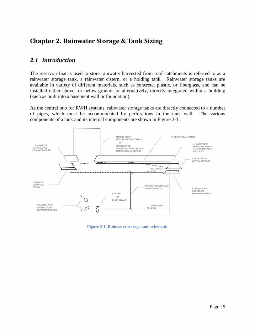
As the central hub for RWH systems, rainwater storage tanks are directly connected to a number
of pipes, which must be accommodated by perforations in the tank wall. The various
components of a tank and its internal components are shown in Figure 2-1.
Figure 2-1. Rainwater storage tank schematic
LOW WATER
LEVEL
HIGH WATER
LEVEL
ACCESS RISER (BELOW GROUND TANKS)
OR
ACESS HATCH (ABOVE GROUND TANKS & INTEGRATED STORAGE)
6. PUMP
OR
PUMP INTAKE
5. RAINWATER OVERFLOW
DRAINAGE PIPING
RAINWATER STORAGE
TANK CAPACITY
4. RAINWATER PRESSURE PIPING (TO NON-POTABLE FIXTURES)
1. RAINWATER CONVEYANCE
DRAINAGE PIPING
2. TOP-UP DRAINAGE
PIPING
3. ELECTRICAL
SUPPLY CONDUIT
7.WATER LEVEL SENSOR (FLOAT
SWITCHES SHOWN)
8. ELECTRICAL WIRING
Page | 10
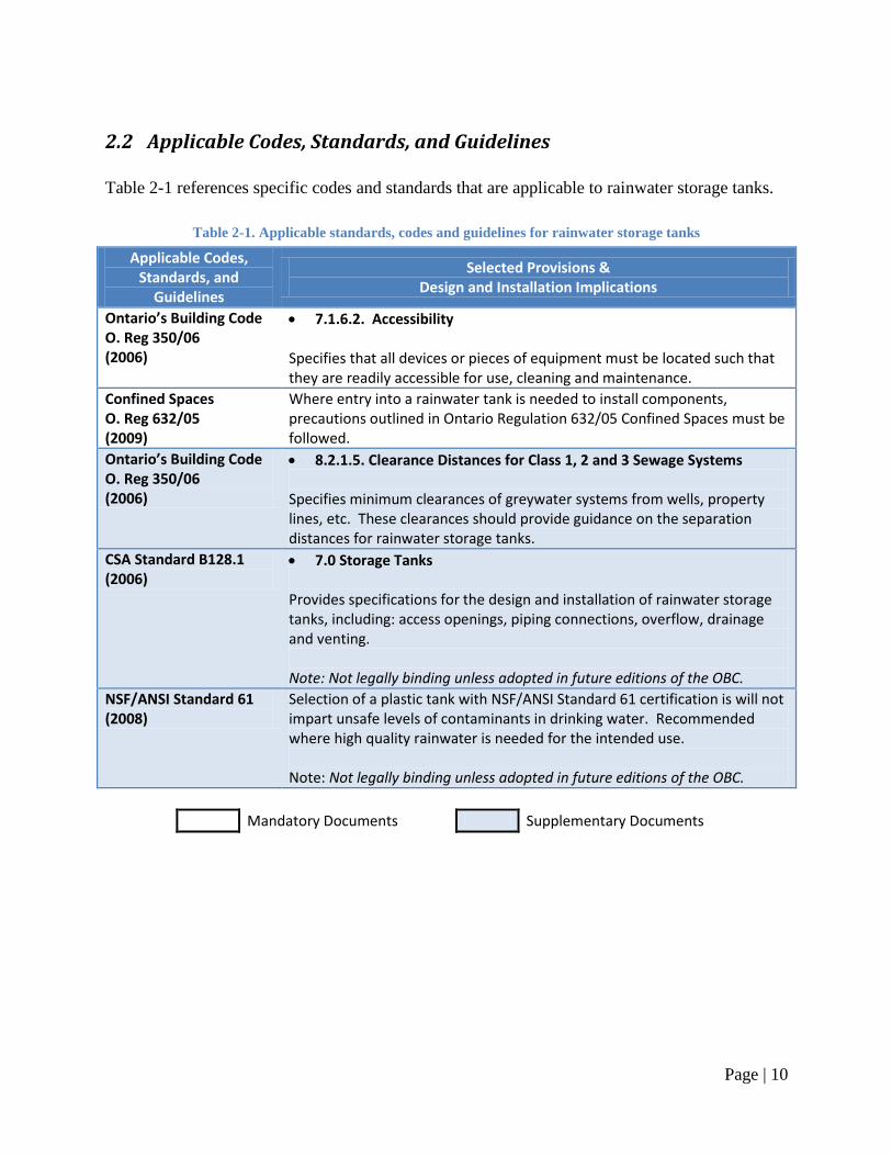
2.2 Applicable Codes, Standards, and Guidelines
Table 2-1 references specific codes and standards that are applicable to rainwater storage tanks.
Table 2-1. Applicable standards, codes and guidelines for rainwater storage tanks
Applicable Codes, Standards, and
Guidelines
Selected Provisions & Design and Installation Implications
Ontario’s Building Code O. Reg 350/06 (2006)
7.1.6.2. Accessibility Specifies that all devices or pieces of equipment must be located such that they are readily accessible for use, cleaning and maintenance.
Confined Spaces O. Reg 632/05 (2009)
Where entry into a rainwater tank is needed to install components, precautions outlined in Ontario Regulation 632/05 Confined Spaces must be followed.
Ontario’s Building Code O. Reg 350/06 (2006)
8.2.1.5. Clearance Distances for Class 1, 2 and 3 Sewage Systems
Specifies minimum clearances of greywater systems from wells, property lines, etc. These clearances should provide guidance on the separation distances for rainwater storage tanks.
CSA Standard B128.1 (2006)
7.0 Storage Tanks Provides specifications for the design and installation of rainwater storage tanks, including: access openings, piping connections, overflow, drainage and venting. Note: Not legally binding unless adopted in future editions of the OBC.
NSF/ANSI Standard 61 (2008)
Selection of a plastic tank with NSF/ANSI Standard 61 certification is will not impart unsafe levels of contaminants in drinking water. Recommended where high quality rainwater is needed for the intended use. Note: Not legally binding unless adopted in future editions of the OBC.
Mandatory Documents Supplementary Documents

Page | 11
2.3 Design & Installation Guidelines
Design and installation guidelines: Note: refer to Section 2.2 Applicable Codes, Standards, and Guidelines for the specific provisions that
apply when the term ―in accordance with applicable provincial codes and regulations‖ is used.
1. Determine the rainwater storage tank capacity:
a. If the rainwater storage tank will be used for stormwater retention and/or as part
of a stormwater management system, the tank shall be sized as required by local
authorities (refer to Chapter 6. Overflow Provisions & Stormwater Management
for details);
b. For storage tanks used for rainwater harvesting purposes:
i. Use the Rainwater Harvesting System Design Tool (refer to Appendix B
for instructions on accessing the Design Tool), or
ii. Use the method provided in the Rainwater Storage Tank Sizing Table
section of Appendix B.
c. If sizing the tank without reference to the Design Tool or Tank Sizing Table,
consider:
i. The unused volume (typically referred to as the ‗dead space‘) when
selecting tank size. If unknown, assume 20% of tank capacity will be
dead space,
ii. The collection losses from pre-storage treatment devices (refer to Chapter
3.Rainwater Quality & Treatment for details).
2. Determine the type of material utilized for the rainwater tank, based on:
a. Placement (above- or below-ground, or integrated storage);
b. Storage volume requirements;
c. Engineering specifications (see Section 2.2 Applicable Codes, Standards, and
Guidelines for applicable standards and consult with manufacturers for further
specifications); and
d. Connected rainwater fixtures and desired quality. (See Section 3.2 Applicable
Codes, Standards, and Guidelines for applicable standards).
3. Determine the location of the rainwater storage tank:
a. For all rainwater storage tank locations:
i. Ensure the location allows for:
1. Proper drainage of rainwater through the conveyance network
(refer to Chapter 1. Rainwater Catchment & Conveyance for
details),
2. Proper drainage of make-up water through top-up drainage piping
(refer to Chapter 4. Make-up Water System and Backflow
Prevention for details),
3. Proper drainage of rainwater from the storage tank to an
appropriate stormwater discharge location (refer to Chapter 6.
Overflow Provisions & Stormwater Management for details).
Page | 12
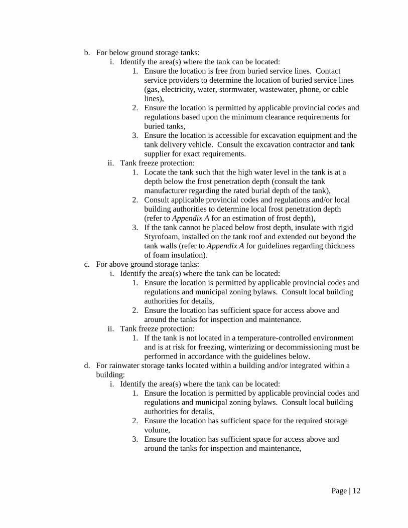
b. For below ground storage tanks:
i. Identify the area(s) where the tank can be located:
1. Ensure the location is free from buried service lines. Contact
service providers to determine the location of buried service lines
(gas, electricity, water, stormwater, wastewater, phone, or cable
lines),
2. Ensure the location is permitted by applicable provincial codes and
regulations based upon the minimum clearance requirements for
buried tanks,
3. Ensure the location is accessible for excavation equipment and the
tank delivery vehicle. Consult the excavation contractor and tank
supplier for exact requirements.
ii. Tank freeze protection:
1. Locate the tank such that the high water level in the tank is at a
depth below the frost penetration depth (consult the tank
manufacturer regarding the rated burial depth of the tank),
2. Consult applicable provincial codes and regulations and/or local
building authorities to determine local frost penetration depth
(refer to Appendix A for an estimation of frost depth),
3. If the tank cannot be placed below frost depth, insulate with rigid
Styrofoam, installed on the tank roof and extended out beyond the
tank walls (refer to Appendix A for guidelines regarding thickness
of foam insulation).
c. For above ground storage tanks:
i. Identify the area(s) where the tank can be located:
1. Ensure the location is permitted by applicable provincial codes and
regulations and municipal zoning bylaws. Consult local building
authorities for details,
2. Ensure the location has sufficient space for access above and
around the tanks for inspection and maintenance.
ii. Tank freeze protection:
1. If the tank is not located in a temperature-controlled environment
and is at risk for freezing, winterizing or decommissioning must be
performed in accordance with the guidelines below.
d. For rainwater storage tanks located within a building and/or integrated within a
building:
i. Identify the area(s) where the tank can be located:
1. Ensure the location is permitted by applicable provincial codes and
regulations and municipal zoning bylaws. Consult local building
authorities for details,
2. Ensure the location has sufficient space for the required storage
volume,
3. Ensure the location has sufficient space for access above and
around the tanks for inspection and maintenance,
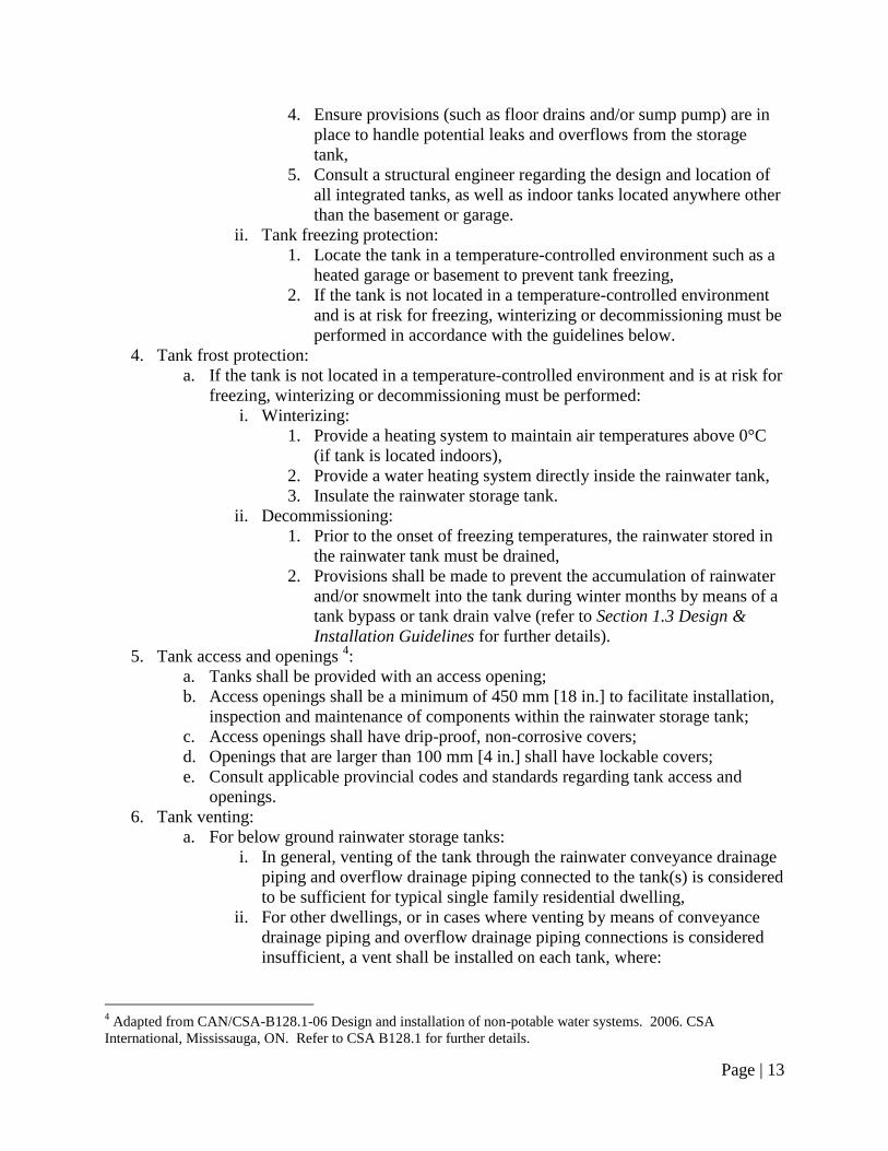
Page | 13
4. Ensure provisions (such as floor drains and/or sump pump) are in
place to handle potential leaks and overflows from the storage
tank,
5. Consult a structural engineer regarding the design and location of
all integrated tanks, as well as indoor tanks located anywhere other
than the basement or garage.
ii. Tank freezing protection:
1. Locate the tank in a temperature-controlled environment such as a
heated garage or basement to prevent tank freezing,
2. If the tank is not located in a temperature-controlled environment
and is at risk for freezing, winterizing or decommissioning must be
performed in accordance with the guidelines below.
4. Tank frost protection:
a. If the tank is not located in a temperature-controlled environment and is at risk for
freezing, winterizing or decommissioning must be performed:
i. Winterizing:
1. Provide a heating system to maintain air temperatures above 0°C
(if tank is located indoors),
2. Provide a water heating system directly inside the rainwater tank,
3. Insulate the rainwater storage tank.
ii. Decommissioning:
1. Prior to the onset of freezing temperatures, the rainwater stored in
the rainwater tank must be drained,
2. Provisions shall be made to prevent the accumulation of rainwater
and/or snowmelt into the tank during winter months by means of a
tank bypass or tank drain valve (refer to Section 1.3 Design &
Installation Guidelines for further details).
5. Tank access and openings 4:
a. Tanks shall be provided with an access opening;
b. Access openings shall be a minimum of 450 mm [18 in.] to facilitate installation,
inspection and maintenance of components within the rainwater storage tank;
c. Access openings shall have drip-proof, non-corrosive covers;
d. Openings that are larger than 100 mm [4 in.] shall have lockable covers;
e. Consult applicable provincial codes and standards regarding tank access and
openings.
6. Tank venting:
a. For below ground rainwater storage tanks:
i. In general, venting of the tank through the rainwater conveyance drainage
piping and overflow drainage piping connected to the tank(s) is considered
to be sufficient for typical single family residential dwelling,
ii. For other dwellings, or in cases where venting by means of conveyance
drainage piping and overflow drainage piping connections is considered
insufficient, a vent shall be installed on each tank, where:
4 Adapted from CAN/CSA-B128.1-06 Design and installation of non-potable water systems. 2006. CSA
International, Mississauga, ON. Refer to CSA B128.1 for further details.
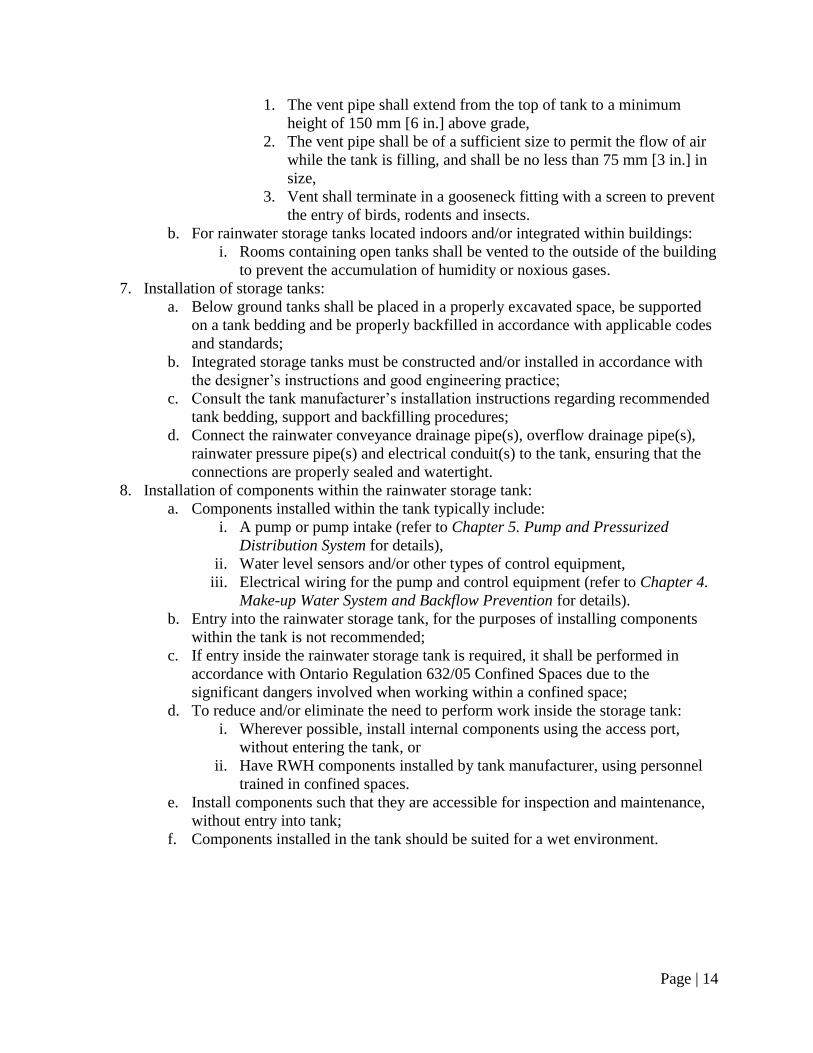
Page | 14
1. The vent pipe shall extend from the top of tank to a minimum
height of 150 mm [6 in.] above grade,
2. The vent pipe shall be of a sufficient size to permit the flow of air
while the tank is filling, and shall be no less than 75 mm [3 in.] in
size,
3. Vent shall terminate in a gooseneck fitting with a screen to prevent
the entry of birds, rodents and insects.
b. For rainwater storage tanks located indoors and/or integrated within buildings:
i. Rooms containing open tanks shall be vented to the outside of the building
to prevent the accumulation of humidity or noxious gases.
7. Installation of storage tanks:
a. Below ground tanks shall be placed in a properly excavated space, be supported
on a tank bedding and be properly backfilled in accordance with applicable codes
and standards;
b. Integrated storage tanks must be constructed and/or installed in accordance with
the designer‘s instructions and good engineering practice;
c. Consult the tank manufacturer‘s installation instructions regarding recommended
tank bedding, support and backfilling procedures;
d. Connect the rainwater conveyance drainage pipe(s), overflow drainage pipe(s),
rainwater pressure pipe(s) and electrical conduit(s) to the tank, ensuring that the
connections are properly sealed and watertight.
8. Installation of components within the rainwater storage tank:
a. Components installed within the tank typically include:
i. A pump or pump intake (refer to Chapter 5. Pump and Pressurized
Distribution System for details),
ii. Water level sensors and/or other types of control equipment,
iii. Electrical wiring for the pump and control equipment (refer to Chapter 4.
Make-up Water System and Backflow Prevention for details).
b. Entry into the rainwater storage tank, for the purposes of installing components
within the tank is not recommended;
c. If entry inside the rainwater storage tank is required, it shall be performed in
accordance with Ontario Regulation 632/05 Confined Spaces due to the
significant dangers involved when working within a confined space;
d. To reduce and/or eliminate the need to perform work inside the storage tank:
i. Wherever possible, install internal components using the access port,
without entering the tank, or
ii. Have RWH components installed by tank manufacturer, using personnel
trained in confined spaces.
e. Install components such that they are accessible for inspection and maintenance,
without entry into tank;
f. Components installed in the tank should be suited for a wet environment.
Page | 15
Chapter 3. Rainwater Quality & Treatment
3.1 Introduction
Rainwater Quality & Treatment Guidelines
The 2006 edition of Ontario‘s Building Code specifies, in Sentence 7.1.5.3.(2) of the Code, that
rainwater may be used for toilet and urinal flushing providing that the rainwater is ―free of
solids‖5 . The 2006 edition of Ontario‘s Building Code, however, does not specify the degree of
treatment required for rainwater to be considered ―free of solids.‖ Thus, the quality of rainwater
and the need for treatment must be evaluated in the context of connected fixtures. Connected
fixtures where there is minimal contact with the rainwater do not require the same quality of
water as applications where users come into direct contact with the water. Treatment needs
should be determined on a case by case basis by local building or health authorities, considering
the recommendations of designers and preferences of end users.
Treatment Options
The quality of harvested rainwater varies greatly based on environmental and site conditions. It
can be improved through simple measures in the design, installation and maintenance process,
prior to the addition of any specific water treatment technology. Best practices to mitigate the
impacts of environmental and site conditions on rainwater quality are provided in the Design &
Installation Guidelines below.
Additional treatment can be provided if necessary through specialized technologies installed
either prior to storage, or after storage and immediately prior to use. The advantages and
disadvantages associated with these treatment approaches are summarized in Table 3-1.
5 Ontario‘s Building Code. 2006. Ministry of Municipal Affairs and Housing, Toronto, ON.
Page | 16
Table 3-1. Comparison of advantages and disadvantages associated with Pre- and Post-storage treatment
Treatment Location
Advantages Disadvantages
Pre-storage treatment
Simple in design; operates using gravity flow (no electricity or high pressure requirements)
Prevents large particles from accumulating in the storage tank
Reduces requirements for post-storage treatment devices (or can preclude their use altogether)
Susceptible to freezing
Requires regular cleaning and maintenance. Poorly-maintained devices may prevent rainwater from being conveyed to tank or may permit untreated rainwater to enter the tank
Multiple collection points may require a number of localized pre-treatment devices, increasing cost
Post-storage treatment
Very high quality of water can be achieved
Located inside building, so no freezing risks
Can be used to treat more complex quality issues (i.e., pine needles in tank that create tannic acids)
May require maintenance and replacement of filters, chemicals, or other materials
End quality depends on incoming rainwater quality and maintenance of pre-storage treatment devices
Generally more expensive than pre-storage treatment
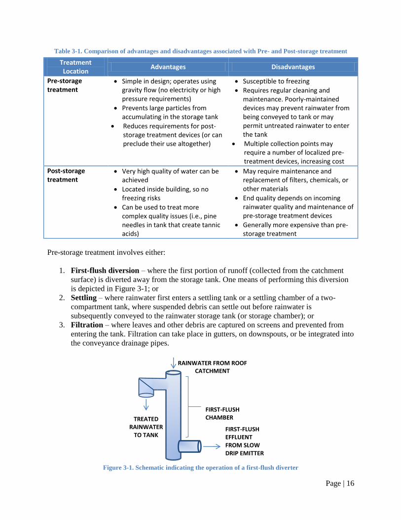
Pre-storage treatment involves either:
1. First-flush diversion – where the first portion of runoff (collected from the catchment
surface) is diverted away from the storage tank. One means of performing this diversion
is depicted in Figure 3-1; or
2. Settling – where rainwater first enters a settling tank or a settling chamber of a two-
compartment tank, where suspended debris can settle out before rainwater is
subsequently conveyed to the rainwater storage tank (or storage chamber); or
3. Filtration – where leaves and other debris are captured on screens and prevented from
entering the tank. Filtration can take place in gutters, on downspouts, or be integrated into
the conveyance drainage pipes.
Figure 3-1. Schematic indicating the operation of a first-flush diverter
FIRST-FLUSH CHAMBER
FIRST-FLUSH EFFLUENT FROM SLOW DRIP EMITTER
RAINWATER FROM ROOF CATCHMENT
TREATED RAINWATER
TO TANK
Page | 17
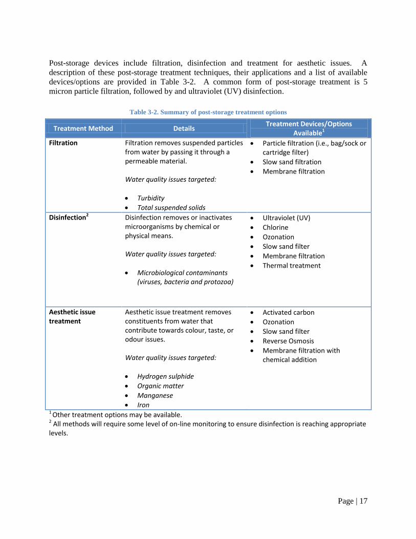
Post-storage devices include filtration, disinfection and treatment for aesthetic issues. A
description of these post-storage treatment techniques, their applications and a list of available
devices/options are provided in Table 3-2. A common form of post-storage treatment is 5
micron particle filtration, followed by and ultraviolet (UV) disinfection.
Table 3-2. Summary of post-storage treatment options
Treatment Method Details Treatment Devices/Options
Available1
Filtration
Filtration removes suspended particles from water by passing it through a permeable material. Water quality issues targeted:
Turbidity
Total suspended solids
Particle filtration (i.e., bag/sock or cartridge filter)
Slow sand filtration
Membrane filtration
Disinfection2
Disinfection removes or inactivates microorganisms by chemical or physical means. Water quality issues targeted:
Microbiological contaminants (viruses, bacteria and protozoa)
Ultraviolet (UV)
Chlorine
Ozonation
Slow sand filter
Membrane filtration
Thermal treatment
Aesthetic issue treatment
Aesthetic issue treatment removes constituents from water that contribute towards colour, taste, or odour issues. Water quality issues targeted:
Hydrogen sulphide
Organic matter
Manganese
Iron
Activated carbon
Ozonation
Slow sand filter
Reverse Osmosis
Membrane filtration with chemical addition
1 Other treatment options may be available. 2 All methods will require some level of on-line monitoring to ensure disinfection is reaching appropriate levels.
Page | 18
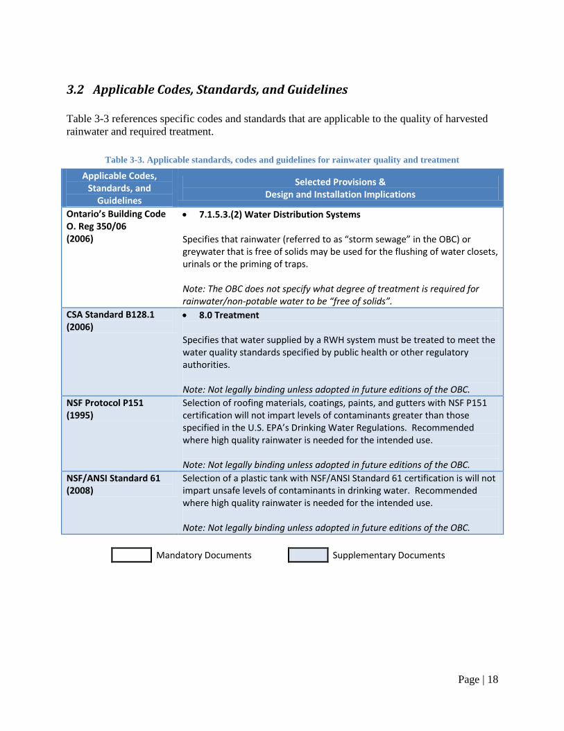
3.2 Applicable Codes, Standards, and Guidelines
Table 3-3 references specific codes and standards that are applicable to the quality of harvested
rainwater and required treatment.
Table 3-3. Applicable standards, codes and guidelines for rainwater quality and treatment
Applicable Codes, Standards, and
Guidelines
Selected Provisions & Design and Installation Implications
Ontario’s Building Code O. Reg 350/06 (2006)
7.1.5.3.(2) Water Distribution Systems Specifies that rainwater (referred to as “storm sewage” in the OBC) or greywater that is free of solids may be used for the flushing of water closets, urinals or the priming of traps. Note: The OBC does not specify what degree of treatment is required for rainwater/non-potable water to be “free of solids”.
CSA Standard B128.1 (2006)
8.0 Treatment Specifies that water supplied by a RWH system must be treated to meet the water quality standards specified by public health or other regulatory authorities. Note: Not legally binding unless adopted in future editions of the OBC.
NSF Protocol P151 (1995)
Selection of roofing materials, coatings, paints, and gutters with NSF P151 certification will not impart levels of contaminants greater than those specified in the U.S. EPA’s Drinking Water Regulations. Recommended where high quality rainwater is needed for the intended use. Note: Not legally binding unless adopted in future editions of the OBC.
NSF/ANSI Standard 61 (2008)
Selection of a plastic tank with NSF/ANSI Standard 61 certification is will not impart unsafe levels of contaminants in drinking water. Recommended where high quality rainwater is needed for the intended use. Note: Not legally binding unless adopted in future editions of the OBC.
Mandatory Documents Supplementary Documents
Page | 19
3.3 Design & Installation Guidelines
Design and installation guidelines: Note: refer to Section 3.2 Applicable Codes, Standards, and Guidelines for the specific provisions
that apply when the term ―in accordance with applicable provincial codes and regulations‖ is
used.
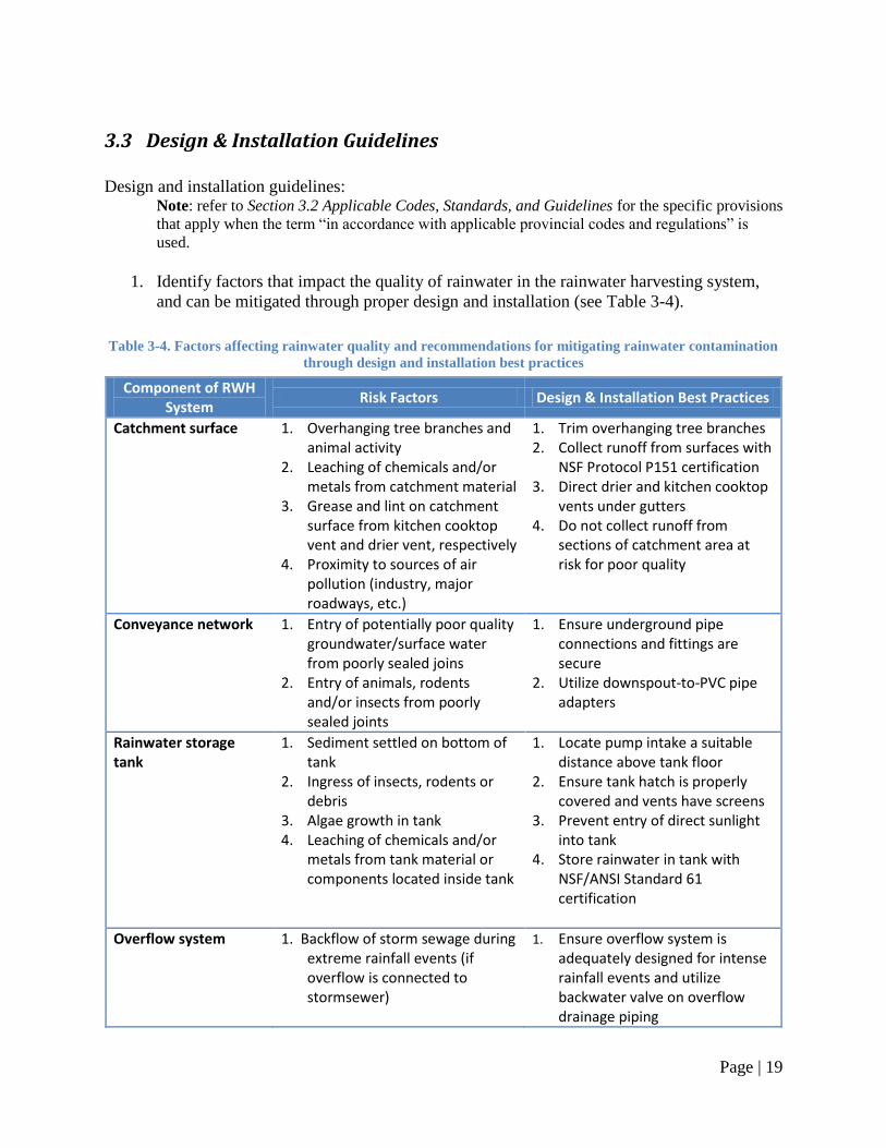
1. Identify factors that impact the quality of rainwater in the rainwater harvesting system,
and can be mitigated through proper design and installation (see Table 3-4).
Table 3-4. Factors affecting rainwater quality and recommendations for mitigating rainwater contamination
through design and installation best practices
Component of RWH System
Risk Factors Design & Installation Best Practices
Catchment surface 1. Overhanging tree branches and animal activity
2. Leaching of chemicals and/or metals from catchment material
3. Grease and lint on catchment surface from kitchen cooktop vent and drier vent, respectively
4. Proximity to sources of air pollution (industry, major roadways, etc.)
1. Trim overhanging tree branches 2. Collect runoff from surfaces with
NSF Protocol P151 certification 3. Direct drier and kitchen cooktop
vents under gutters 4. Do not collect runoff from
sections of catchment area at risk for poor quality
Conveyance network
1. Entry of potentially poor quality groundwater/surface water from poorly sealed joins
2. Entry of animals, rodents and/or insects from poorly sealed joints
1. Ensure underground pipe connections and fittings are secure
2. Utilize downspout-to-PVC pipe adapters
Rainwater storage tank
1. Sediment settled on bottom of tank
2. Ingress of insects, rodents or debris
3. Algae growth in tank 4. Leaching of chemicals and/or
metals from tank material or components located inside tank
1. Locate pump intake a suitable distance above tank floor
2. Ensure tank hatch is properly covered and vents have screens
3. Prevent entry of direct sunlight into tank
4. Store rainwater in tank with NSF/ANSI Standard 61 certification
Overflow system
1. Backflow of storm sewage during extreme rainfall events (if overflow is connected to stormsewer)
1. Ensure overflow system is adequately designed for intense rainfall events and utilize backwater valve on overflow drainage piping
Page | 20
2. Determine rainwater quality and treatment requirements:
a. In the Province of Ontario, rainwater may be used for:
i. Toilet and urinal flushing, and
ii. Sub-surface irrigation and below ground irrigation.
b. Consult the applicable provincial codes and regulations to verify the fixtures for
which connection to rainwater is permitted;
c. Consult the applicable provincial codes and regulations and local authorities
regarding quality and treatment requirements for the permitted rainwater fixtures;
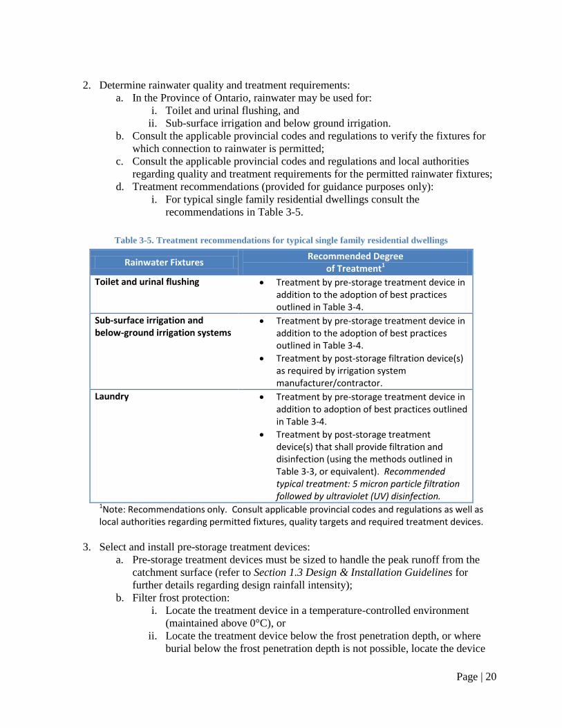
d. Treatment recommendations (provided for guidance purposes only):
i. For typical single family residential dwellings consult the
recommendations in Table 3-5.
Table 3-5. Treatment recommendations for typical single family residential dwellings
Rainwater Fixtures Recommended Degree
of Treatment1
Toilet and urinal flushing Treatment by pre-storage treatment device in addition to the adoption of best practices outlined in Table 3-4.
Sub-surface irrigation and below-ground irrigation systems
Treatment by pre-storage treatment device in addition to the adoption of best practices outlined in Table 3-4.
Treatment by post-storage filtration device(s) as required by irrigation system manufacturer/contractor.
Laundry Treatment by pre-storage treatment device in addition to adoption of best practices outlined in Table 3-4.
Treatment by post-storage treatment device(s) that shall provide filtration and disinfection (using the methods outlined in Table 3-3, or equivalent). Recommended typical treatment: 5 micron particle filtration followed by ultraviolet (UV) disinfection.
1Note: Recommendations only. Consult applicable provincial codes and regulations as well as local authorities regarding permitted fixtures, quality targets and required treatment devices.
3. Select and install pre-storage treatment devices:
a. Pre-storage treatment devices must be sized to handle the peak runoff from the
catchment surface (refer to Section 1.3 Design & Installation Guidelines for
further details regarding design rainfall intensity);
b. Filter frost protection:
i. Locate the treatment device in a temperature-controlled environment
(maintained above 0°C), or
ii. Locate the treatment device below the frost penetration depth, or where
burial below the frost penetration depth is not possible, locate the device
Page | 21
below ground with appropriate insulation (refer to Appendix A for details),
or
iii. Decommission/disconnect the treatment device from the conveyance
network and drain the device prior to the onset of cold weather (refer to
Section 2.3 Design & Installation Guidelines for details).
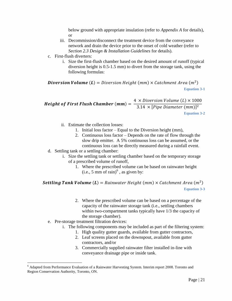
c. First-flush diverters:
i. Size the first-flush chamber based on the desired amount of runoff (typical
diversion height is 0.5-1.5 mm) to divert from the storage tank, using the
following formulas:
( ) ( ) ( )
Equation 3-1
( ) ( )
[ ( )]
Equation 3-2
ii. Estimate the collection losses:
1. Initial loss factor – Equal to the Diversion height (mm),
2. Continuous loss factor – Depends on the rate of flow through the
slow drip emitter. A 5% continuous loss can be assumed, or the
continuous loss can be directly measured during a rainfall event.
d. Settling tank or a settling chamber:
i. Size the settling tank or settling chamber based on the temporary storage
of a prescribed volume of runoff,
1. Where the prescribed volume can be based on rainwater height
(i.e., 5 mm of rain)6 , as given by:
( ) ( ) ( )
Equation 3-3
2. Where the prescribed volume can be based on a percentage of the
capacity of the rainwater storage tank (i.e., settling chambers
within two-compartment tanks typically have 1/3 the capacity of
the storage chamber).
e. Pre-storage treatment filtration devices:
i. The following components may be included as part of the filtering system:
1. High quality gutter guards, available from gutter contractors,
2. Leaf screens placed on the downspout, available from gutter
contractors, and/or
3. Commercially supplied rainwater filter installed in-line with
conveyance drainage pipe or inside tank.
6 Adapted from Performance Evaluation of a Rainwater Harvesting System. Interim report 2008. Toronto and
Region Conservation Authority, Toronto, ON.
Page | 22
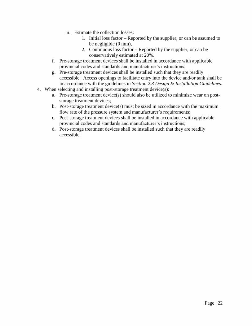
ii. Estimate the collection losses:
1. Initial loss factor – Reported by the supplier, or can be assumed to
be negligible (0 mm),
2. Continuous loss factor – Reported by the supplier, or can be
conservatively estimated at 20%.
f. Pre-storage treatment devices shall be installed in accordance with applicable
provincial codes and standards and manufacturer‘s instructions;
g. Pre-storage treatment devices shall be installed such that they are readily
accessible. Access openings to facilitate entry into the device and/or tank shall be
in accordance with the guidelines in Section 2.3 Design & Installation Guidelines.
4. When selecting and installing post-storage treatment device(s):
a. Pre-storage treatment device(s) should also be utilized to minimize wear on post-
storage treatment devices;
b. Post-storage treatment device(s) must be sized in accordance with the maximum
flow rate of the pressure system and manufacturer‘s requirements;
c. Post-storage treatment devices shall be installed in accordance with applicable
provincial codes and standards and manufacturer‘s instructions;
d. Post-storage treatment devices shall be installed such that they are readily
accessible.
Page | 23
Chapter 4. Make-up Water System and Backflow Prevention
4.1 Introduction
There will occasionally be times when there is insufficient rainfall to meet the demands placed
upon the rainwater harvesting system, and the storage tank will run dry. Rainwater harvesting
systems need to have a system in place to recognize when there is insufficient rainwater and
either trigger a warning light or switch to an alternative supply of water. This system is often
referred to as a ―make-up‖ or ―back-up‖ system, with two general options are available:
1. Top-up – The rainwater storage tank can be partially filled, either manually or
automatically, with make-up supplies of water from municipal (potable), or private water
sources;
2. Bypass – The rainwater supply from the pressure system can be shut-off, either manually
or automatically, and water from municipal or private sources can be directed through the
rainwater pressure piping.
Of these options, only top-up systems are permitted by the 2006 edition of Ontario‘s Building
Code. The bypass method contravenes Subsection 7.7.1, of the Code which states that ―a non-
potable water system shall not be connected to a potable water system.‖7 As such, top-up based
make-up systems are recommended.
Control Equipment
The main control equipment used to construct a make-up water system include:
1. Solenoid valve to open and close the potable water supply pipe,
2. Water level sensor (usually float switches for residential applications) to control the
solenoid valve and protect against dry running the pump, and
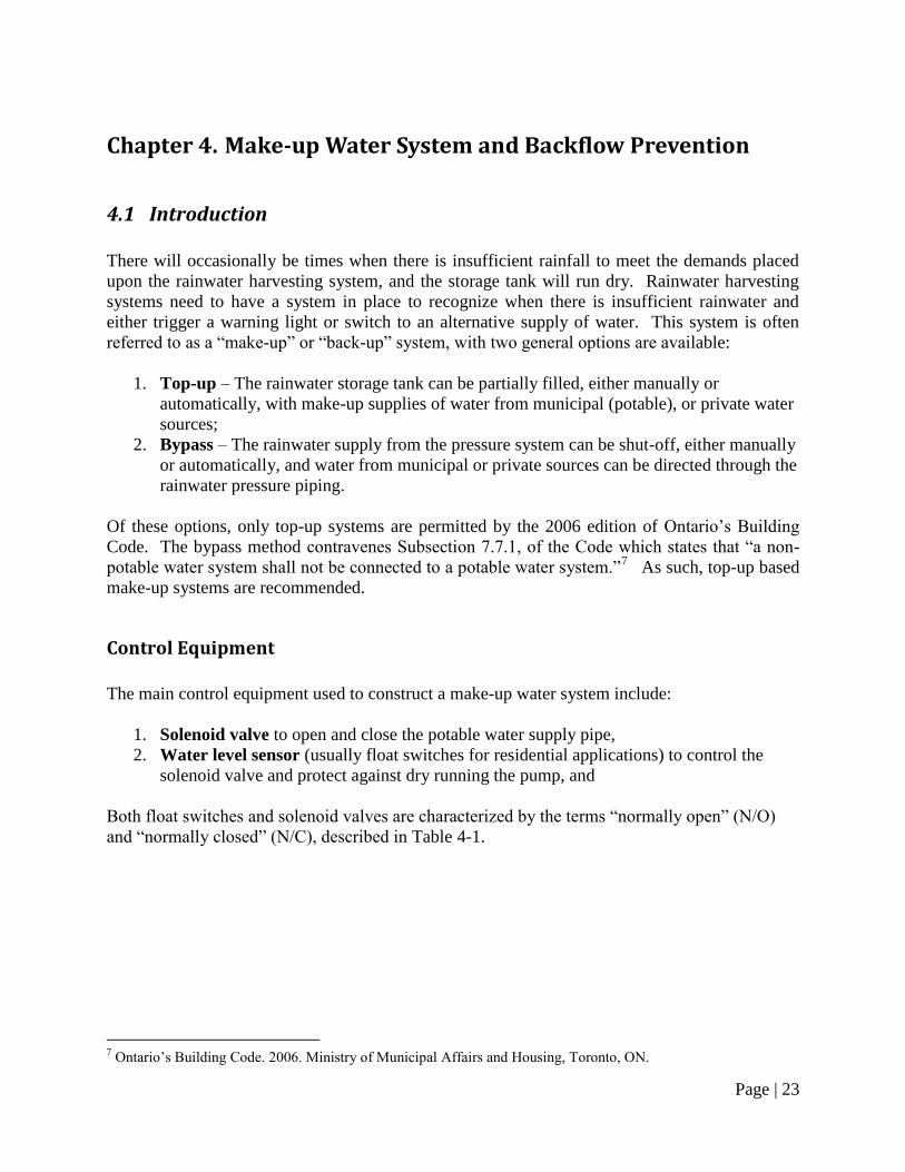
Both float switches and solenoid valves are characterized by the terms ―normally open‖ (N/O)
and ―normally closed‖ (N/C), described in Table 4-1.
7 Ontario‘s Building Code. 2006. Ministry of Municipal Affairs and Housing, Toronto, ON.
Page | 24
Table 4-1. Differences between Normally Closed and Normally Open float switches and solenoid valves
Control Equipment Normally Closed (N/C) Normally Open (N/O)
Float switch
Permits power supply (turns things “on”) when the switch is in the “down” position (when there is a high water level in the tank)
Permits power supply (turns things “on”) when the switch is in the “up” position (when the water level is below the float switch)
Solenoid valve
When power is supplied, the valve is in an “open” state and permits the flow of water. Valve closes when power supply is discontinued.
When power is supplied, the valve is in a “closed” state and prevents the flow of water. Valve opens when power supply is discontinued.
In the down position, the float switch can initiate an automatic partial top-up of the tank from
municipal water sources. The volume of make-up water needed depends on the ―tether length‖
of the float switch, while the tether point determines the water level at which this process takes
place. To maximize rainwater use, the tether length should be as short as possible and the tether
point should be as low as possible, while ensuring that the water level does not drop below the
pump.
While some pumps may have built in dry run protection, additional protection may be required if
the built in protection is based on a timer and not water levels. A float switch can be used for dry
run protection in the following configurations:
1. Pump/float switch – For manual top-up systems, the storage tank may run dry before
additional volumes of make-up water can be supplied. A Normally Open (N/O) float
switch should be wired into the pump for the purpose of dry run protection.
2. Solenoid valve/float switch – For automatic top-up systems, a Normally Closed (N/C)
float switch should be connected to the solenoid valve supplying make-up water. If the
float switch is located at a height above the pump intake, it will prevent the pump from
dry running. However, if make-up supplies are insufficient, a dry run situation may still
take place.
3. Dual float switches – For automatic top-up systems, independent float switches can be
connected to both the solenoid valve supplying make-up water and the pump (N/C and
N/O, respectively). The pump is protected from dry running in the event that insufficient
back-up supplies are available. This method is recommended as it provides the greatest
protection for the pump.
Cross-connections, Backflow Prevention and Premise Isolation
In the case of RWH systems, zone protection is required for the make-up system and premise
isolation is required for the building. Numerous devices exist to provide backflow prevention.
The 2006 edition of Ontario‘s Building Code prohibits any direct connection between a potable
and non-potable system and therefore an air gap is required for zone protection of the top-up
system. Following CAN/CSA-B64.10-07, premise isolation may be provided by a dual check
Page | 25
valve, if there is no direct connection between the RWH system and the mains system. All
applicable provincial codes and regulations as well as municipal bylaws must be consulted to
determine what degree of backflow prevention is required (refer to Section 4.2 Applicable Codes,
Standards, and Guidelines for details).
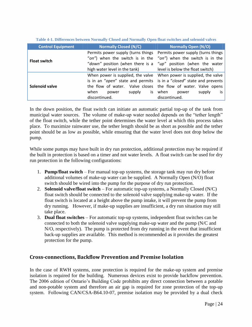
Figure 4-1 shows the various components of the automatic top-up system.
Figure 4-1. Components of an automatic top-up system
Air Gap
The typical method of backflow prevention used for top-up systems is the air gap. An air gap is
one of the simplest methods of preventing backflow, and involves a physical separation between
two sections of pipe that is open to the atmosphere (shown in Figure 4-1 and Figure 4-2).
Rigid structure
Cable ties
ON
OFF
Electrical wire
Rainwater tank
Pump intake
OFF
ON Volume of top-up water
Dead space
Jet pump
Tether point
Air gap
Float switch (N/C)
Float switch (N/O)
Top-up drainage piping
Solenoid valve (N/C) on potable water
supply pipe
Page | 26
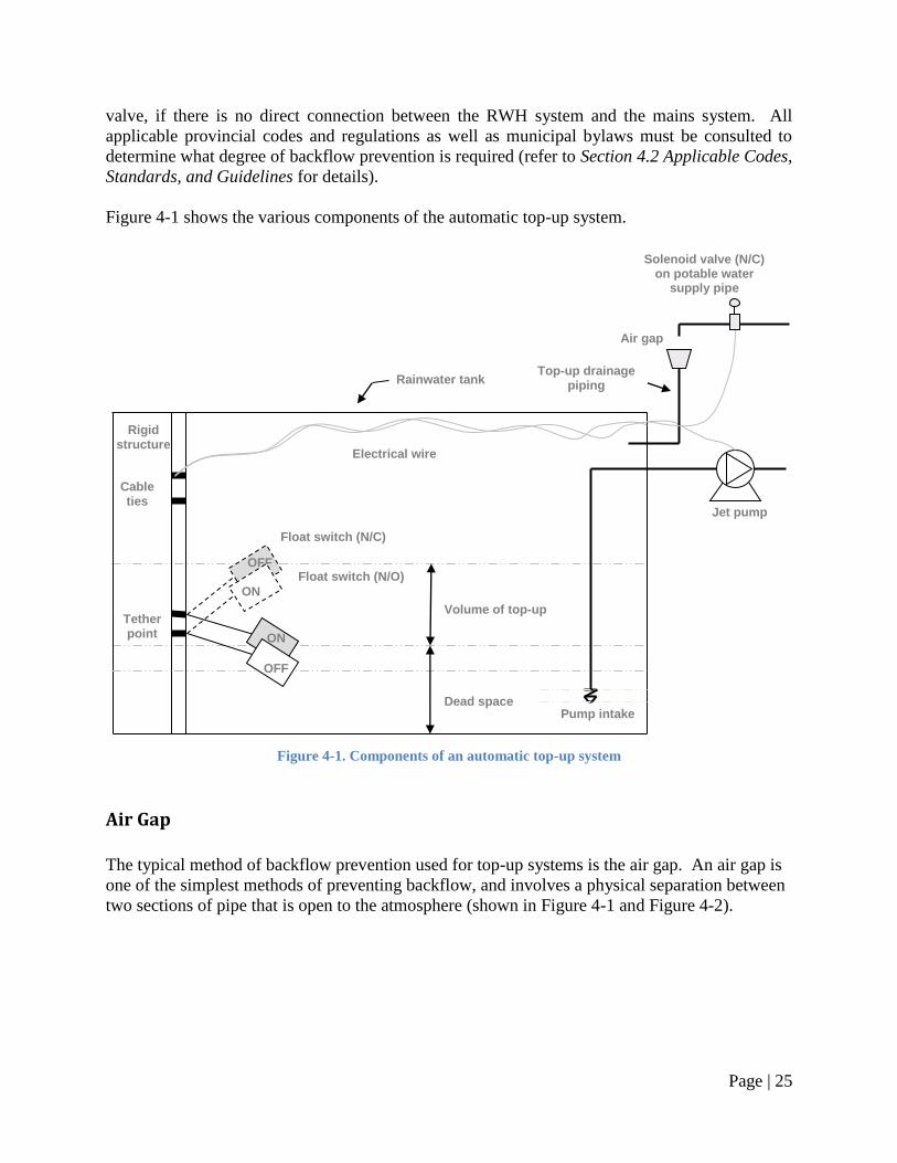
Figure 4-2. Schematic drawing of a top-up system with an air gap
8
This physical break prevents the backflow of water since even if rainwater backed up from the
tank to the gap, it would spill from the gap and not come into contact with the potable water
supply. The air gap must be located higher than the overflow drainage piping from the tank and
the overflow drainage piping must remain free of blockage so that excess rainwater flows to the
overflow system and does not back up and overflow at the air gap.
8 Adapted from Ontario‘s Building Code. 2006. Ministry for Municipal Affairs and Housing, Toronto, ON.
Manual/Solenoid valve
Air gap
Must have the following: 1. Visible inside house or building 2. Located above flood level rim
(overflow) of rainwater storage tank 3. Min. 25 mm [1 in.] in height or twice
the diameter of the water supply pipe
Gravity flow to storage tank
through top-up drainage piping
Potable water supply
Page | 27
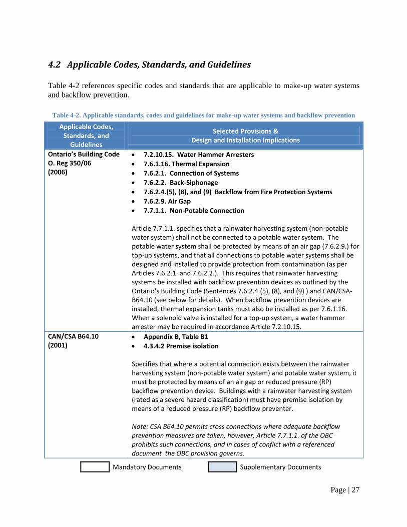
4.2 Applicable Codes, Standards, and Guidelines
Table 4-2 references specific codes and standards that are applicable to make-up water systems
and backflow prevention.
Table 4-2. Applicable standards, codes and guidelines for make-up water systems and backflow prevention
Applicable Codes, Standards, and
Guidelines
Selected Provisions & Design and Installation Implications
Ontario’s Building Code O. Reg 350/06 (2006)
7.2.10.15. Water Hammer Arresters
7.6.1.16. Thermal Expansion
7.6.2.1. Connection of Systems
7.6.2.2. Back-Siphonage
7.6.2.4.(5), (8), and (9) Backflow from Fire Protection Systems
7.6.2.9. Air Gap
7.7.1.1. Non-Potable Connection Article 7.7.1.1. specifies that a rainwater harvesting system (non-potable water system) shall not be connected to a potable water system. The potable water system shall be protected by means of an air gap (7.6.2.9.) for top-up systems, and that all connections to potable water systems shall be designed and installed to provide protection from contamination (as per Articles 7.6.2.1. and 7.6.2.2.). This requires that rainwater harvesting systems be installed with backflow prevention devices as outlined by the Ontario’s Building Code (Sentences 7.6.2.4.(5), (8), and (9) ) and CAN/CSA-B64.10 (see below for details). When backflow prevention devices are installed, thermal expansion tanks must also be installed as per 7.6.1.16. When a solenoid valve is installed for a top-up system, a water hammer arrester may be required in accordance Article 7.2.10.15.
CAN/CSA B64.10 (2001)
Appendix B, Table B1
4.3.4.2 Premise isolation Specifies that where a potential connection exists between the rainwater harvesting system (non-potable water system) and potable water system, it must be protected by means of an air gap or reduced pressure (RP) backflow prevention device. Buildings with a rainwater harvesting system (rated as a severe hazard classification) must have premise isolation by means of a reduced pressure (RP) backflow preventer. Note: CSA B64.10 permits cross connections where adequate backflow prevention measures are taken, however, Article 7.7.1.1. of the OBC prohibits such connections, and in cases of conflict with a referenced document the OBC provision governs.
Mandatory Documents Supplementary Documents
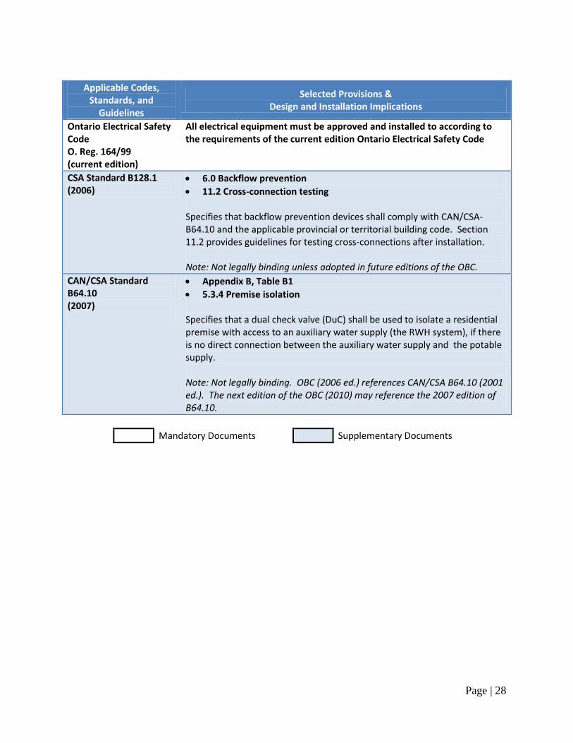
Page | 28
Applicable Codes, Standards, and
Guidelines
Selected Provisions & Design and Installation Implications
Ontario Electrical Safety Code O. Reg. 164/99 (current edition)
All electrical equipment must be approved and installed to according to the requirements of the current edition Ontario Electrical Safety Code
CSA Standard B128.1 (2006)
6.0 Backflow prevention
11.2 Cross-connection testing Specifies that backflow prevention devices shall comply with CAN/CSA-B64.10 and the applicable provincial or territorial building code. Section 11.2 provides guidelines for testing cross-connections after installation. Note: Not legally binding unless adopted in future editions of the OBC.
CAN/CSA Standard B64.10 (2007)
Appendix B, Table B1
5.3.4 Premise isolation Specifies that a dual check valve (DuC) shall be used to isolate a residential premise with access to an auxiliary water supply (the RWH system), if there is no direct connection between the auxiliary water supply and the potable supply. Note: Not legally binding. OBC (2006 ed.) references CAN/CSA B64.10 (2001 ed.). The next edition of the OBC (2010) may reference the 2007 edition of B64.10.
Mandatory Documents Supplementary Documents
Page | 29
4.3 Design & Installation Guidelines
Design and installation guidelines: Note: refer to Section 4.2 Applicable Codes, Standards, and Guidelines for the specific provisions
that apply when the term ―in accordance with applicable provincial codes and regulations‖ is used.
1. Determine the type of make-up system:
a. Automatic top-up system (recommended);
b. Manual top-up system;
c. No make-up system (not recommended).
2. Plan the layout of the top-up system:
a. A top-up system is generally comprised of the following:
i. Water level sensor(s) located in the rainwater storage tank,
ii. A solenoid valve located on the potable water supply pipe,
iii. An air gap,
iv. Top-up drainage piping conveying make-up water to the rainwater storage
tank, and
v. Electrical conduit(s), containing wiring from the water level sensor(s) and
pump.
b. Determine the location of the solenoid valve and air gap in accordance with the
guidelines provided below;
c. Plan route of top-up drainage piping from the air gap to the tank (refer to Section
1.3 Design & Installation Guidelines for guidelines and applicable provincial
codes and regulations regarding drainage piping);
d. Plan route of electrical conduit(s) from the location of the solenoid valve and
power supply to the tank (refer to Section 1.3 Design & Installation Guidelines
for piping installation guidelines);
e. Ensure that there are no buried service lines (gas, electricity, water, stormwater,
wastewater, phone, or cable lines) in the area where digging will take place to
accommodate the buried top-up drainage piping and/or electrical conduit by
contacting the municipality and service providers.
3. Water level sensors:
a. Select the appropriate water level sensor(s) for the RWH system (float switch,
ultrasonic level sensor, or other);
b. Float switches:
i. Select the type of float switch:
1. Solenoid valve actuation is typically provided by a N/C float
switch, for top-up systems,
2. Pump dry run protection is typically provided by a N/O float
switch.
ii. Electrical requirements:
1. The voltage rating of the float switch must match that of the device
it controls (120 V or 240 V),
2. The power rating (Watts [W] or Horsepower [HP]) of the float
switch must be sufficient to carry the total load of the device it
Page | 30
controls, or alternatively, float switches may be low voltage and
used to activate the pump through relays in a control panel,
3. Spliced electrical wiring must be water tight and be of sufficient
electrical rating as determined by the loads handled by the float
switch and the total length of wiring,
4. All electrical connections for float switches must be made by a
licensed electrician in accordance with the manufacturer‘s
instructions.
c. Float switch installation:
i. The float switch shall be tethered to a rigid freestanding object, such as a
vertical section of pipe or the pump, that:
1. Permits the float switch to rise and fall without any obstructions,
2. Is located in area where it is easily accessible and can be
withdrawn from the tank without requiring entry into the tank.
ii. To set the operating parameters of the float switch:
1. To maximize rainwater collection, the tether length should be as
short as possible: 75 mm [3 in.]. Refer to the manufacturer‘s
installation instructions for details,
2. To maximize rainwater collection, the tether point should be as
low as possible (such that the float is 50 mm [2 in.] above the
pump intake when in the down position),
3. If utilizing a dual float switch configuration, the float switch
controlling the solenoid valve should be located a minimum of 75
mm [3 in.] above the float switch controlling the pump.
d. Other water level sensors shall be selected and installed in accordance with
applicable provincial codes and regulations, where all electrical connections must
be made by a licensed electrician in accordance with the manufacturer‘s
instructions.
4. Solenoid valves and shut-off valves:
a. Select the type and size of solenoid valve and/or shut-off valve:
i. All valves must be suitable for potable water and pressure applications,
ii. Valve openings must be no less than the size of the piping where they are
located,
iii. Top-up systems typically use a N/C solenoid valve,
iv. Solenoid valves with a ‗slow close‘ or ‗soft close‘ are recommended.
b. Electrical requirements:
i. Solenoid valves must be wired into a power supply in conjunction with a
water level sensor;
c. Solenoid valve and shut-off valve installation:
i. Solenoid valves or shut-off valves used as part of a top-up system shall be
installed on the potable water supply pipe upstream of the air gap,
ii. Solenoid valves must be installed by a licensed plumber and electrician in
accordance with the manufacturer‘s installation instructions.
d. Water hammer protection:
i. If a ‗slow close‘ or ‗soft close‘ solenoid valve is not utilized a water
hammer arrester shall be installed on the potable water supply piping
Page | 31
upstream of the solenoid valve in accordance with applicable provincial
codes and regulations.
5. Air gap:
a. An air gap is required as part of a top-up system for the purpose backflow
prevention (zone protection);
b. Air gaps shall be designed and installed in accordance with applicable provincial
codes and regulations. For guidance purposes only, the following guidelines are
provided:
i. The gap must be unobstructed – mechanical supports fixing the potable
water supply pipe to the top-up drainage pipe, or other components located
at or between the potable water supply pipe and top-up drainage pipe is
not permitted,
ii. The air gap must be located in an area where it can be observed and
inspected,
iii. The air gap must be installed at a height above the flood level rim
(overflow) of the rainwater storage tank. If not, there is a risk that
rainwater will back up the top-up drainage pipe and overflow from the air
gap,
iv. The air gap height must be at least 25 mm [1 in.] or twice the diameter of
the water supply pipe.
c. Splash and water damage prevention:
i. To prevent make-up water from splashing at the air gap, install the
following:
1. Flow restrictor, installed upstream of the solenoid valve, and/or
2. Aerator, installed where the potable water supply pipe terminates,
and/or
3. Extended length of vertical pipe with the end of the pipe cut at a
angle no less than 45° (to produce laminar flow), installed where
the potable water supply pipe terminates above the air gap.
ii. To prevent water damage to rooms where the air gap is located:
1. Locate air gaps near a floor drain,
2. Install an overflow on the top-up drainage pipe, located
downstream of the air gap to direct excess make-up water to the
sanitary sewer (where permitted by local authorities),
3. Appropriately size and slope the top-up drainage piping.
d. Make-up water flow rate:
i. To ensure RWH system operation during top-up, the following measures
are recommended:
1. The flow rate of make-up water should be equivalent to that of the
maximum flow rate of the rainwater supply pump, or
2. The water level sensor(s) shall be configured to provide a
sufficient reserve volume in the rainwater storage tank (i.e., where
said reserve volume shall be equivalent to that of the average daily
rainwater demand for the RWH system).
Page | 32
6. Top-up drainage pipes:
a. Pipe material:
i. ABS pipe (recommended), where
ii. Pipe selected must be approved by the applicable provincial codes and
regulations, and industry standards (CSA, ASTM, etc.).
b. Pipe size and slope:
i. Top-up drainage piping shall be sized to handle the maximum flow rate of
make-up water discharged at the air gap,
ii. For a typical single family residential dwelling (provided for guidance
purposes only):
1. Top-up drainage piping shall be no less than 50 mm [2 in.] in size
when served by a potable water supply pipe no more than 18 mm
[3/4 in.] in size.
iii. Ensure a minimum slope of 0.5-2% (the greater the slope the better) is
maintained throughout the pipe length.
c. Consult the applicable provincial codes and regulations pertaining to the
installation of drainage piping (refer to Section 1.2 Applicable Codes, Standards,
and Guidelines for details).
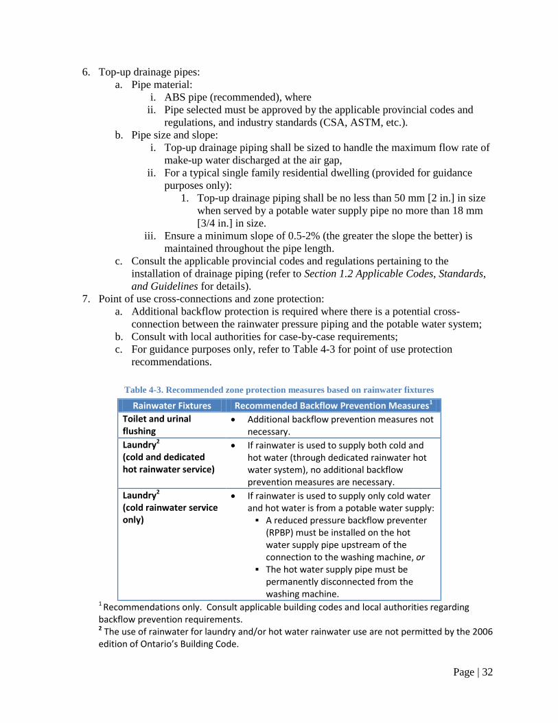
7. Point of use cross-connections and zone protection:
a. Additional backflow protection is required where there is a potential cross-
connection between the rainwater pressure piping and the potable water system;
b. Consult with local authorities for case-by-case requirements;
c. For guidance purposes only, refer to Table 4-3 for point of use protection
recommendations.
Table 4-3. Recommended zone protection measures based on rainwater fixtures
Rainwater Fixtures Recommended Backflow Prevention Measures1
Toilet and urinal flushing
Additional backflow prevention measures not necessary.
Laundry2 (cold and dedicated hot rainwater service)
If rainwater is used to supply both cold and hot water (through dedicated rainwater hot water system), no additional backflow prevention measures are necessary.
Laundry2 (cold rainwater service only)
If rainwater is used to supply only cold water and hot water is from a potable water supply: A reduced pressure backflow preventer
(RPBP) must be installed on the hot water supply pipe upstream of the connection to the washing machine, or
The hot water supply pipe must be permanently disconnected from the washing machine.
1 Recommendations only. Consult applicable building codes and local authorities regarding backflow prevention requirements. 2 The use of rainwater for laundry and/or hot water rainwater use are not permitted by the 2006 edition of Ontario’s Building Code.
Page | 33
8. Premise isolation:
a. Backflow preventers must be installed for the purpose of premise isolation. The
following guidelines are based on CAN/CSA-B64.10-07; however, this edition is
not yet adopted in the 2006 edition of Ontario‘s Building Code (refer to Section
4.2 Applicable Codes, Standards, and Guidelines for further details);
b. Backflow preventer selection:
i. Residential premises with access to an auxiliary water supply (not directly
connected) must be isolated from the potable water supply by a dual check
valve (DuC) backflow preventer,
ii. All other premises with access to an auxilriary water supply (including
residential premises with a direct connection) must be isolated from the
potable water supply by a reduced pressure (RP) backflow preventer. A
double check valve assembly (DCVA) may be permitted, consult
municipal bylaws and local building officials.
c. Protection against thermal expansion:
i. If a backflow preventer is installed for premise isolation, the building
potable water supply piping must be protected from thermal expansion by
installation of an appropriately sized diaphragm expansion tank, selected
and installed in accordance with applicable provincial codes and
regulations.
d. Backflow preventer testing and maintenance:
i. Backflow preventers shall be tested and maintained in accordance with
CAN/CSA-B64.10.1-07 Maintenance and Field Testing of Backflow
Preventers.
9. Electrical wiring:
a. All electrical wiring must be installed in accordance with the applicable
provincial codes and regulations, including the current edition of the Ontario
Electrical Safety Code.
10. Electrical conduit and rainwater service conduit:
a. Wiring located underground shall be provided with mechanical protection by
means of an electrical conduit, or other approved means;
b. To facilitate repair and/or replacement of underground rainwater pressure piping,
piping should be installed inside a rainwater service conduit, where the conduit
material can be flexible drainage tubing (typically referred to as ―Big ‗O‘ ‖
tubing) or other suitable material.
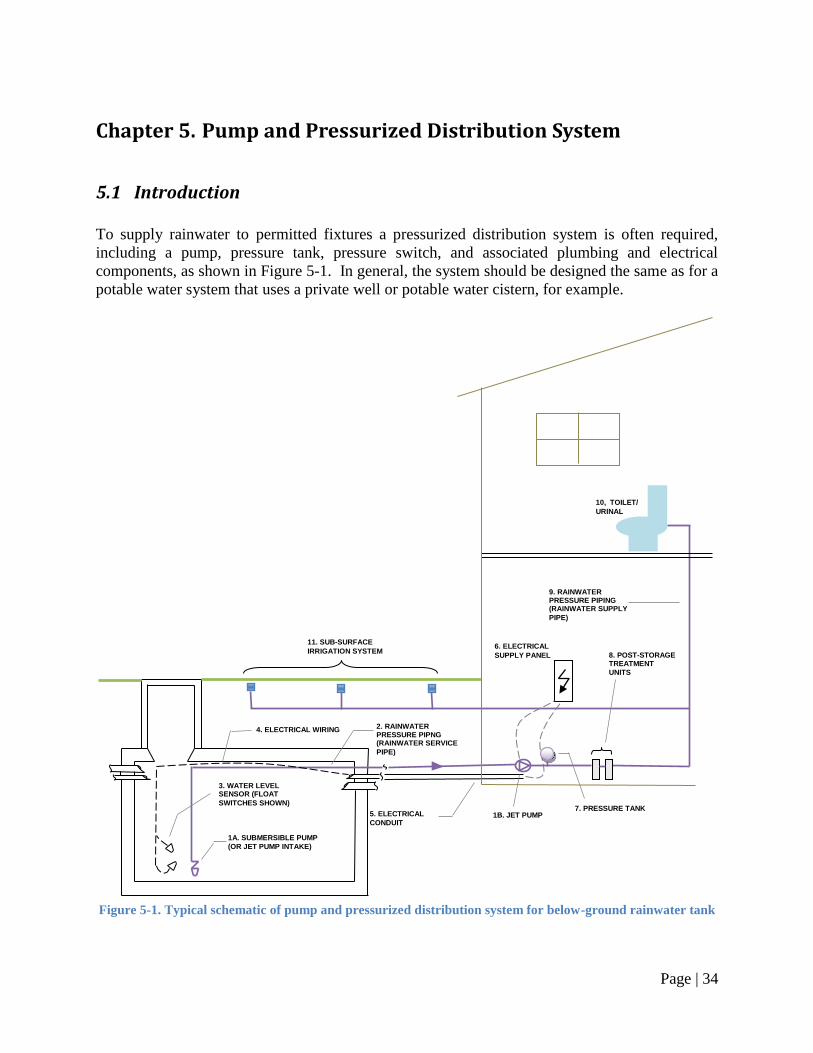
Page | 34
Chapter 5. Pump and Pressurized Distribution System
5.1 Introduction
To supply rainwater to permitted fixtures a pressurized distribution system is often required,
including a pump, pressure tank, pressure switch, and associated plumbing and electrical
components, as shown in Figure 5-1. In general, the system should be designed the same as for a
potable water system that uses a private well or potable water cistern, for example.
Figure 5-1. Typical schematic of pump and pressurized distribution system for below-ground rainwater tank
1A. SUBMERSIBLE PUMP
(OR JET PUMP INTAKE)
2. RAINWATER PRESSURE PIPNG (RAINWATER SERVICE
PIPE)
5. ELECTRICAL
CONDUIT
3. WATER LEVEL SENSOR (FLOAT
SWITCHES SHOWN)
4. ELECTRICAL WIRING
11. SUB-SURFACE
IRRIGATION SYSTEM
6. ELECTRICAL
SUPPLY PANEL
10, TOILET/
URINAL
8. POST-STORAGE TREATMENT
UNITS
9. RAINWATER PRESSURE PIPING (RAINWATER SUPPLY
PIPE)
1B. JET PUMP
7. PRESSURE TANK
Page | 35
Pipes
As seen in Figure 5-1, there are two distinct sections of rainwater pressure piping:
1. Rainwater service pipe – the section of pipe from the storage tank to a jet pump, or the
section of pipe from the storage tank to the pressure tank or control unit, in the case of
submersible pumps;
2. Rainwater supply pipe – the section of pipe from the jet pump (or pressure tank/control
unit for submersible pumps) to the permitted fixtures.
Each section has unique criteria that must be considered during design and installation, resulting
in different pipe material, sizing and installation requirements. For instance, below-ground
rainwater tanks require rainwater service pipe that is suitable for burial and, as this pipe will
always have water in it, it is critical that it is well protected from freezing. Rainwater supply
piping is inside the building and must be installed in accordance with codes to ensure that a
cross-connection is not made. Both sections of pipes must be sized to handle the flow generated
by the pump and ensure that each fixture receives rainwater at a sufficient rate, with service
piping typically requiring larger pipe diameters than supply piping.
Markings
To prevent cross-connections, rainwater piping must be marked to indicate that the pipes contain
non-potable water. Markings for pipe must be distinct and easily recognizable, typically a purple
colour is used to identify the piping as containing non-potable water. An example of pipe
marking is shown in Figure 5-2.
Figure 5-2. Typical marking for rainwater pressure piping
Another means of identifying rainwater pressure piping is to utilize a distinct colour of pipe –
purple – to prevent future plumbing cross-connections.
WARNING: NON-POTABLE WATER — DO NOT DRINK
AVERTISSEMENT : EAU NON-POTABLE — NE PAS BOIRE
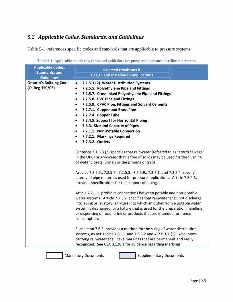
Page | 36
5.2 Applicable Codes, Standards, and Guidelines
Table 5-1 references specific codes and standards that are applicable to pressure systems.
Table 5-1. Applicable standards, codes and guidelines for pump and pressure distribution systems
Applicable Codes, Standards, and
Guidelines
Selected Provisions & Design and Installation Implications
Ontario’s Building Code (O. Reg 350/06)
7.1.5.3.(2) Water Distribution Systems
7.2.5.5. Polyethylene Pipe and Fittings
7.2.5.7. Crosslinked Polyethylene Pipe and Fittings
7.2.5.8. PVC Pipe and Fittings
7.2.5.9. CPVC Pipe, Fittings and Solvent Cements
7.2.7.1. Copper and Brass Pipe
7.2.7.4. Copper Tube
7.3.4.5. Support for Horizontal Piping
7.6.3. Size and Capacity of Pipes
7.7.1.1. Non-Potable Connection
7.7.2.1. Markings Required
7.7.3.2. Outlets
Sentence 7.1.5.3.(2) specifies that rainwater (referred to as “storm sewage” in the OBC) or greywater that is free of solids may be used for the flushing of water closets, urinals or the priming of traps. Articles 7.2.5.5., 7.2.5.7., 7.2.5.8., 7.2.5.9., 7.2.7.1. and 7.2.7.4. specify approved pipe materials used for pressure applications. Article 7.3.4.5. provides specifications for the support of piping. Article 7.7.1.1. prohibits connections between potable and non-potable water systems. Article 7.7.3.2. specifies that rainwater shall not discharge into a sink or lavatory, a fixture into which an outlet from a potable water system is discharged, or a fixture that is used for the preparation, handling or dispensing of food, drink or products that are intended for human consumption. Subsection 7.6.3. provides a method for the sizing of water distribution systems, as per Tables 7.6.3.1 and 7.6.3.2 and A-7.6.1.1.(1). Also, pipes carrying rainwater shall have markings that are permanent and easily recognized. See CSA B.128.1 for guidance regarding markings.
Mandatory Documents Supplementary Documents
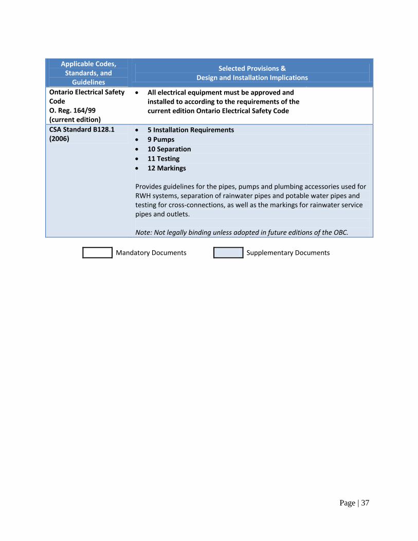
Page | 37
Applicable Codes, Standards, and
Guidelines
Selected Provisions & Design and Installation Implications
Ontario Electrical Safety Code O. Reg. 164/99 (current edition)
All electrical equipment must be approved and installed to according to the requirements of the current edition Ontario Electrical Safety Code
CSA Standard B128.1 (2006)
5 Installation Requirements
9 Pumps
10 Separation
11 Testing
12 Markings Provides guidelines for the pipes, pumps and plumbing accessories used for RWH systems, separation of rainwater pipes and potable water pipes and testing for cross-connections, as well as the markings for rainwater service pipes and outlets. Note: Not legally binding unless adopted in future editions of the OBC.
Mandatory Documents Supplementary Documents
Page | 38
5.3 Design & Installation Guidelines
Design and installation guidelines: Note: refer to Section 5.2 Applicable Codes, Standards, and Guidelines for the specific provisions
that apply when the term ―in accordance with applicable provincial codes and regulations‖ is
used.
1. Determine the fixtures connected to rainwater:
a. In the Province of Ontario, rainwater may be used for:
i. Toilet and urinal flushing, and
ii. Sub-surface irrigation and below ground irrigation.
b. Consult the applicable provincial codes and regulations to verify the fixtures for
which connection to rainwater is permitted.
2. Select the pump:
a. Determine the style and operating characteristics:
i. Style: jet pump or submersible pump,
ii. Controller configuration: constant speed or variable speed drive (VSD),
iii. Operating voltage: 120V or 240V.
b. Determine the required flow rate:
i. Consult applicable codes and regulations, industry standards, local
authorities and irrigation system manufacturer (if applicable) regarding the
minimum flow rate to be supplied by the pump,
ii. For guidance purposes only, a method for estimating minimum pump flow
rate, based upon the maximum peak demand sizing method, is provided in
Appendix C.
c. Determine the pump head:
i. Consult applicable codes and regulations regarding the minimum flow
pressure and maximum static pressure provided by the pump,
ii. A method for determining the pump head is provided in Appendix C.
d. Consult the pump manufacturer or supplier, or use pump manufacturer‘s ‗pump
curve‘ charts, to select the appropriate pump model, given the pump style and
operating characteristics, required flow rate, and pump head.
e. If pump downtime is not permitted or not desired:
i. Provide a generator or battery backup for the pump, and/or
ii. Provide a backup pump or duplex pump arrangement.
3. Select the pressure tank:
a. Consult the pump manufacturer or supplier regarding the minimum size of
pressure tank for the pump, based upon pump controller configuration, and pump
flow rate;
b. For guidance purposes only, a method for sizing the pressure tank for constant
speed pumps is provided in Appendix C.
Page | 39
4. Plan the layout of the pump and pressurized distribution system:
a. Plan route of the rainwater service piping from the jet pump, pressure tank or
control unit to the tank (refer to Section 1.3 Design & Installation Guidelines for
guidelines and applicable provincial codes and regulations regarding installation
of underground piping);
b. Plan route of the rainwater supply piping from the jet pump, pressure tank or
control unit to the permitted fixtures;
c. Plan route of electrical conduit(s) from the location of the power supply to the
tank (route with float switch wiring where possible, refer to Chapter 4. Make-up
Water System and Backflow Prevention for further details);
d. Ensure that there are no buried service lines (gas, electricity, water, stormwater,
wastewater, phone, or cable lines) in the area where digging will take place to
accommodate buried rainwater service piping and/or electrical conduit by
contacting the municipality and service providers.
5. Rainwater pressure piping:
a. Rainwater pressure piping is comprised of two distinct sections of pipe:
i. Rainwater service pipe:
1. Piping from the storage tank to a jet pump, or
2. Piping from the storage tank to the pressure tank or control unit, in
the case of submersible pumps.
ii. Rainwater supply pipe:
1. Piping from the jet pump (or pressure tank/control unit for
submersible pumps) to the permitted fixtures.
b. Rainwater service pipes:
i. Pipe material:
1. Polyethylene pipe (recommended), where
2. Pipe selected must be approved by applicable provincial codes and
industry standards (CSA, ASTM, etc.).
ii. Pipe size:
1. Pipe shall be sized to handle the maximum flow rate of the pump
in accordance with the pump manufacturer‘s instructions,
2. For estimation purposes, service pipe size can be calculated using
the method provided in Appendix C.
iii. Tank connection:
1. Rainwater service piping should enter the tank at a height no lower
than that of the overflow drainage piping, or ideally, at a height 50
mm [2 in.] above the top of the overflow drainage pipe(s) entering
the tank, or
2. Where entering the tank at a height no lower than that of the
overflow drainage piping exposes the rainwater service piping to
frost, rainwater service piping may enter the tank at a lower height,
provided the tank connection is water tight.
c. Rainwater supply pipes:
i. Pipe material:
1. Crosslinked polyethylene (PEX) (recommended), where
Page | 40
2. Pipe selected must be approved by applicable provincial codes and
industry standards (CSA, ASTM, etc.).
ii. Pipe size:
1. Consult the applicable provincial codes and regulations pertaining
to water supply pipe sizing,
2. For estimation purposes, supply pipe size can be calculated using
the method provided in Appendix C.
6. Installation of rainwater pressure piping:
a. Connection:
i. Rainwater pressure piping shall not be connected to a potable water
system,
ii. Rainwater pressure piping shall only connect to fixtures permitted by
applicable provincial codes and regulations.
b. Support and protection:
i. Underground piping shall be located in a properly excavated space, be
supported and properly backfilled in accordance with applicable provincial
codes and regulations,
ii. Piping inside a building shall be supported in accordance with applicable
provincial codes and regulations,
iii. Piping shall be protected from frost (refer to Section 1.3 Design &
Installation Guidelines for details).
c. Operation and maintenance considerations:
i. Rainwater service piping connected to a jet pump must be installed on a
horizontal, or on a consistent upward slope from the storage tank to the
pump,
ii. To minimize the possibility of leaks, underground rainwater service piping
should be installed with no, or few, pipe fittings,
iii. To facilitate repair and/or replacement of underground rainwater service
piping, piping should be installed inside a rainwater service conduit, where
the conduit material can be flexible drainage tubing (typically referred to
as ―Big ‗O‘ ‖ tubing) or other suitable material.
d. Underground non-metallic pipes should be installed with ‗tracer tape‘ (also
referred to as ‗tracer wire‘) at a height of 300 mm [12 in.] above the pipe for the
purpose of locating as-installed piping.
7. Pipe markings9 :
a. All rainwater pressure pipes shall be clearly identified and marked in accordance
with applicable provincial codes and regulations;
b. Pipes shall be marked as follows:
i. Text/legend:
1. WARNING: NON-POTABLE WATER — DO NOT DRINK
AVERTISSEMENT : EAU NON-POTABLE — NE PAS BOIRE
2. Text must be legible with letters no less than 5 mm in height,
except where pressure pipe size makes 5 mm high letters
impractical.
9 Adapted from CAN/CSA-B128.1-06 Design and installation of non-potable water systems. 2006. CSA
International, Mississauga, ON. Refer to CAN/CSA-B128.1-06 for further details.
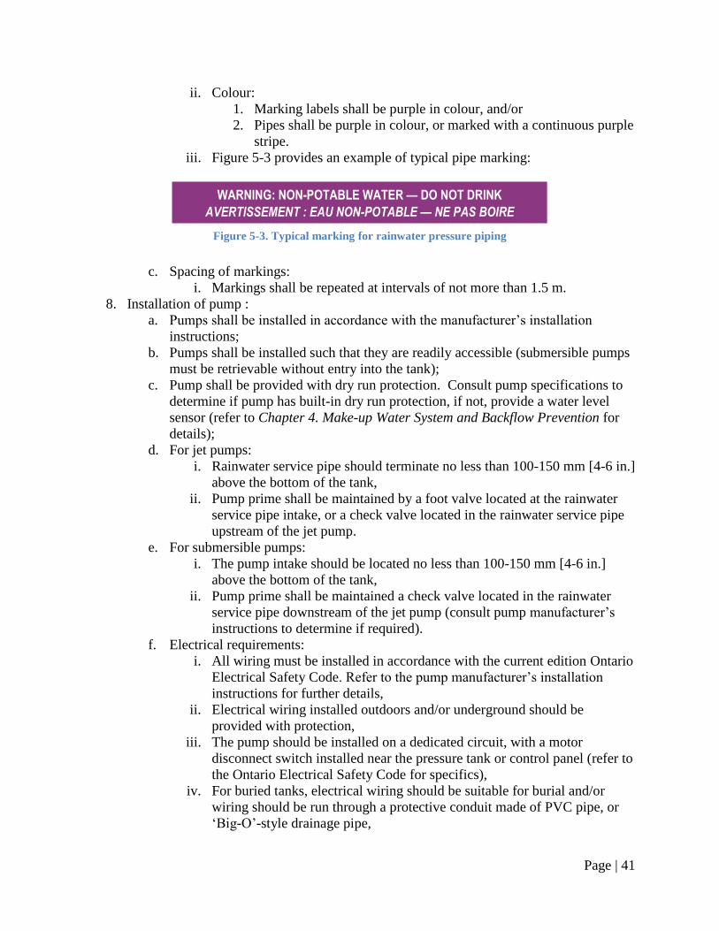
Page | 41
ii. Colour:
1. Marking labels shall be purple in colour, and/or
2. Pipes shall be purple in colour, or marked with a continuous purple
stripe.
iii. Figure 5-3 provides an example of typical pipe marking:
Figure 5-3. Typical marking for rainwater pressure piping
c. Spacing of markings:
i. Markings shall be repeated at intervals of not more than 1.5 m.
8. Installation of pump :
a. Pumps shall be installed in accordance with the manufacturer‘s installation
instructions;
b. Pumps shall be installed such that they are readily accessible (submersible pumps
must be retrievable without entry into the tank);
c. Pump shall be provided with dry run protection. Consult pump specifications to
determine if pump has built-in dry run protection, if not, provide a water level
sensor (refer to Chapter 4. Make-up Water System and Backflow Prevention for
details);
d. For jet pumps:
i. Rainwater service pipe should terminate no less than 100-150 mm [4-6 in.]
above the bottom of the tank,
ii. Pump prime shall be maintained by a foot valve located at the rainwater
service pipe intake, or a check valve located in the rainwater service pipe
upstream of the jet pump.
e. For submersible pumps:
i. The pump intake should be located no less than 100-150 mm [4-6 in.]
above the bottom of the tank,
ii. Pump prime shall be maintained a check valve located in the rainwater
service pipe downstream of the jet pump (consult pump manufacturer‘s
instructions to determine if required).
f. Electrical requirements:
i. All wiring must be installed in accordance with the current edition Ontario
Electrical Safety Code. Refer to the pump manufacturer‘s installation
instructions for further details,
ii. Electrical wiring installed outdoors and/or underground should be
provided with protection,
iii. The pump should be installed on a dedicated circuit, with a motor
disconnect switch installed near the pressure tank or control panel (refer to
the Ontario Electrical Safety Code for specifics),
iv. For buried tanks, electrical wiring should be suitable for burial and/or
wiring should be run through a protective conduit made of PVC pipe, or
‗Big-O‘-style drainage pipe,
WARNING: NON-POTABLE WATER — DO NOT DRINK
AVERTISSEMENT : EAU NON-POTABLE — NE PAS BOIRE
Page | 42
v. Buried electrical wiring and/or conduits should be installed in a properly
prepared and backfilled space (refer to Chapter 1. Rainwater Catchment &
Conveyance for details).
9. Installation of pressure tank:
a. Pressure tanks shall be installed in accordance with the manufacturer‘s installation
instructions;
b. Pressure tanks shall be installed such that they are readily accessible;
c. Pressure tanks shall be installed with a means for observing the system pressure,
such as a pressure gauge;
d. The pressure sensor or pressure switch installed with the pressure tank must be
wired in with the pump (and a control panel if applicable);
e. All wiring must be installed in accordance with the current edition Ontario
Electrical Safety Code.
10. Install post-storage treatment devices as required (refer to Chapter 3. Rainwater Quality
& Treatment for details).
11. Commission the pump and pressurized distribution system in accordance with the
manufacturer‘s instructions.
Page | 43
Chapter 6. Overflow Provisions & Stormwater Management
6.1 Introduction
On occasion, the volume of rainwater collected from the roof catchment will exceed the storage
capacity of the rainwater storage tank, causing the tank to overflow. If overflow-handling
provisions are not in place, excess rainwater will back up rainwater conveyance and top-up
drainage piping, until the rainwater reaches a point from which it can most easily
discharge/overflow. This may be at the downspout-to-conveyance pipe transition, or less ideal
locations like the access opening of the tank, or at the air gap of a top-up system. Overflows at
these points may cause damage to the rainwater tank itself, or cause water damage to a building‘s
exterior or interior.
Excess rainwater can be directed to grade, to the storm sewer, or to on onsite infiltration system
(soakaway pit), depending on the characteristics of the site. Ideally overflow volumes can be
conveyed via gravity, but if the tank outlet is located below the storm sewer or grade, pumping
may be required.
The advantages and disadvantages of the different systems are discussed in Table 6-1.
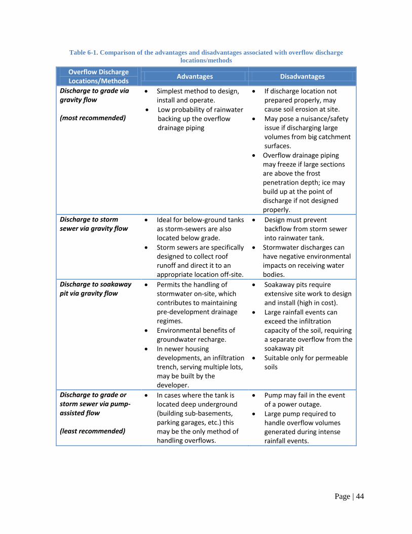
Page | 44
Table 6-1. Comparison of the advantages and disadvantages associated with overflow discharge
locations/methods
Overflow Discharge Locations/Methods
Advantages Disadvantages
Discharge to grade via gravity flow (most recommended)
Simplest method to design, install and operate.
Low probability of rainwater backing up the overflow drainage piping
If discharge location not prepared properly, may cause soil erosion at site.
May pose a nuisance/safety issue if discharging large volumes from big catchment surfaces.
Overflow drainage piping may freeze if large sections are above the frost penetration depth; ice may build up at the point of discharge if not designed properly.
Discharge to storm sewer via gravity flow
Ideal for below-ground tanks as storm-sewers are also located below grade.
Storm sewers are specifically designed to collect roof runoff and direct it to an appropriate location off-site.
Design must prevent backflow from storm sewer into rainwater tank.
Stormwater discharges can have negative environmental impacts on receiving water bodies.
Discharge to soakaway pit via gravity flow
Permits the handling of stormwater on-site, which contributes to maintaining pre-development drainage regimes.
Environmental benefits of groundwater recharge.
In newer housing developments, an infiltration trench, serving multiple lots, may be built by the developer.
Soakaway pits require extensive site work to design and install (high in cost).
Large rainfall events can exceed the infiltration capacity of the soil, requiring a separate overflow from the soakaway pit
Suitable only for permeable soils
Discharge to grade or storm sewer via pump-assisted flow (least recommended)
In cases where the tank is located deep underground (building sub-basements, parking garages, etc.) this may be the only method of handling overflows.
Pump may fail in the event of a power outage.
Large pump required to handle overflow volumes generated during intense rainfall events.
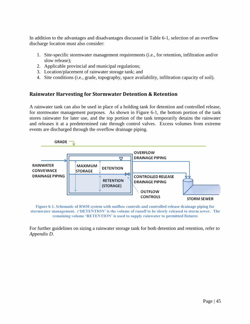
Page | 45
In addition to the advantages and disadvantages discussed in Table 6-1, selection of an overflow
discharge location must also consider:
1. Site-specific stormwater management requirements (i.e., for retention, infiltration and/or
slow release);
2. Applicable provincial and municipal regulations;
3. Location/placement of rainwater storage tank; and
4. Site conditions (i.e., grade, topography, space availability, infiltration capacity of soil).
Rainwater Harvesting for Stormwater Detention & Retention
A rainwater tank can also be used in place of a holding tank for detention and controlled release,
for stormwater management purposes. As shown in Figure 6-1, the bottom portion of the tank
stores rainwater for later use, and the top portion of the tank temporarily detains the rainwater
and releases it at a predetermined rate through control valves. Excess volumes from extreme
events are discharged through the overflow drainage piping.
Figure 6-1. Schematic of RWH system with outflow controls and controlled release drainage piping for
stormwater management. (‘DETENTION’ is the volume of runoff to be slowly released to storm sewer. The
remaining volume ‘RETENTION’ is used to supply rainwater to permitted fixtures
For further guidelines on sizing a rainwater storage tank for both detention and retention, refer to
Appendix D.
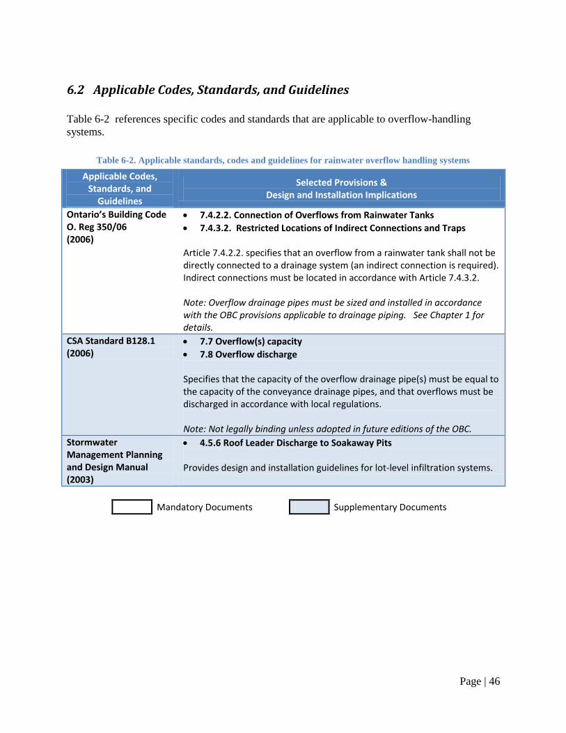
Page | 46
6.2 Applicable Codes, Standards, and Guidelines
Table 6-2 references specific codes and standards that are applicable to overflow-handling
systems.
Table 6-2. Applicable standards, codes and guidelines for rainwater overflow handling systems
Applicable Codes, Standards, and
Guidelines
Selected Provisions & Design and Installation Implications
Ontario’s Building Code O. Reg 350/06 (2006)
7.4.2.2. Connection of Overflows from Rainwater Tanks
7.4.3.2. Restricted Locations of Indirect Connections and Traps Article 7.4.2.2. specifies that an overflow from a rainwater tank shall not be directly connected to a drainage system (an indirect connection is required). Indirect connections must be located in accordance with Article 7.4.3.2. Note: Overflow drainage pipes must be sized and installed in accordance with the OBC provisions applicable to drainage piping. See Chapter 1 for details.
CSA Standard B128.1 (2006)
7.7 Overflow(s) capacity
7.8 Overflow discharge Specifies that the capacity of the overflow drainage pipe(s) must be equal to the capacity of the conveyance drainage pipes, and that overflows must be discharged in accordance with local regulations. Note: Not legally binding unless adopted in future editions of the OBC.
Stormwater Management Planning and Design Manual (2003)
4.5.6 Roof Leader Discharge to Soakaway Pits Provides design and installation guidelines for lot-level infiltration systems.
Mandatory Documents Supplementary Documents
Page | 47
6.3 Design & Installation Guidelines
Design and installation guidelines: Note: refer to Section 6.2 Applicable Codes, Standards, and Guidelines for the specific provisions
that apply when the term ―in accordance with applicable provincial codes and regulations‖ is used.
1. Determine the overflow discharge location and method:
a. Overflow discharge locations include: grade, storm sewer, or soakaway pit;
b. Overflow discharge methods include: gravity flow or pump-assisted flow;
c. Overflow by pump-assisted flow is not recommended;
d. Consult the applicable provincial codes and regulations, municipal bylaws, and
local authorities regarding the permitted overflow discharge locations;
e. Evaluate the feasibility of the overflow discharge locations:
i. Overflow to grade:
1. The overflow discharge location must be at a lower elevation than
the flood level rim of the tank for gravity flow to be feasible.
ii. Overflow to storm sewer:
1. A storm sewer connection must be present at the site,
2. The overflow discharge location must be at a lower elevation than
the flood level rim of the tank for gravity flow to be feasible.
iii. Overflow to soakaway pit:
1. The percolation rate of site soils must be sufficient to permit
infiltration of rainwater overflows discharged into the soakaway pit
(refer to Appendix D for guidelines on sizing soakaway pits).
2. Plan the layout of the overflow system:
a. Plan route of overflow drainage piping from the tank to the overflow discharge
location (refer to Section 1.3 Design & Installation Guidelines for guidelines and
applicable provincial codes and regulations regarding drainage piping);
b. Ensure that there are no buried service lines (gas, electricity, water, stormwater,
wastewater, phone, or cable lines) in the area where digging will take place to
accommodate buried overflow drainage piping by contacting the municipality and
service providers.
3. Overflow pipes:
a. Overflow drainage pipes:
i. Pipe material:
1. PVC SDR35 pipe (recommended), or ABS pipe, where
2. Pipe selected must be approved by applicable provincial codes and
industry standards (CSA, ASTM, etc.).
ii. Pipe size and slope:
1. Overflow drainage piping shall be sized to ensure that the capacity
of overflow drainage pipe(s) are no less than the capacity of the
rainwater conveyance drainage pipe(s),
2. Ensure a minimum slope of 0.5-2% (the greater the slope the
better) is maintained throughout the pipe length,
Page | 48
iii. Tank connection:
1. Overflow drainage piping shall exit the tank at a height no lower
than that of the rainwater conveyance drainage piping, or ideally,
at a height 50 mm [2 in.] below the bottom of the conveyance
drainage pipe(s) entering the tank.
iv. Consult the applicable provincial codes and regulations pertaining to the
installation of drainage piping (refer to Section 1.2 Applicable Codes,
Standards, and Guidelines for details).
b. Overflow pressure pipes:
i. Pipe material:
1. Polyethylene pipe (recommended), where
2. Pipe selected must be approved by applicable provincial codes and
industry standards (CSA, ASTM, etc.).
ii. Pipe size and slope:
1. Overflow pressure piping shall be sized to ensure that the capacity
of overflow pressure pipe(s) are no less than the capacity of the
rainwater conveyance drainage pipe(s).
iii. Consult the applicable provincial codes and regulations pertaining to the
installation of pressure piping (refer to Section 5.2 Applicable Codes,
Standards, and Guidelines for details).
4. Discharging overflows to grade:
a. Overflows must be discharged in a location where rainwater won‘t pond or collect
around building foundations;
b. Erosion prevention measures should be taken;
c. A screen should be installed where the pipe terminates to prevent the entry of
birds, rodents or insects.
5. Discharging overflows to storm sewer:
a. Overflow drainage piping cannot be directly connected to a storm sewer, unless
approved by local authorities;
b. A direct connection may be permitted if a backwater valve is installed on the
overflow drainage pipe. Consult local authorities for approval;
c. An indirect connection can be made by overflowing:
i. To an interceptor tank, which then overflows to storm sewer,
ii. To a soakaway pit, which then overflows to the storm sewer,
iii. Via overland flow to a sewer grate, or
iv. Using an air gap, in the case of above ground tanks.
6. Discharging overflows to a soakaway pit:
a. Consult applicable provincial and municipal guidelines regarding the design and
installation of soakaway pits;
b. For guidance purposes only, soakaway pit design and installation guidelines are
provided in Appendix D;
c. If there is limited space for a soakaway pit or if the soil has a low permeability, it
is recommended that the soakaway pit have its own overflow, discharging
overflows to grade or storm sewer.
Page | 49
7. Overflow discharge pump:
a. If rainwater overflows must be pumped, the pump shall be sized to handle the
capacity of the rainwater conveyance drainage pipe(s);
b. The pump shall be selected and installed in accordance with the guidelines
provided in Chapter 5. Pump and Pressurized Distribution System.
8. Incorporating a RWH system as part of a stormwater management system:
a. Consult the municipality and/or conservation authority regarding how to
incorporate a RWH system into other stormwater management systems;
b. If considering utilizing a rainwater storage tank for both retention and detention
purposes, refer to Appendix D for further details.
Page | 50
Appendix
Appendix A. Rainwater Catchment & Conveyance
Collection Losses from Roof Surfaces Sizing Gutters and Downspouts Sizing Rainwater Conveyance Drainage Piping Frost Penetration Depth & Pipe Freeze Protection
Appendix B. Rainwater Storage & Tank Sizing
Rainwater Harvesting Design Tool Rainwater Storage Tank Sizing Table
Appendix C. Pump and Pressurized Distribution System
Calculation of Required Pump Capacity Calculation of Required Pressure from Pump (Pump Head) Calculation of Friction Loss Calculation of Pressure Tank Size Calculation of Pipe Size
Appendix D. Overflow Provisions & Stormwater Management
Utilizing a Rainwater Storage Tank for Retention & Detention for Stormwater Management Purposes Design & Sizing of Soakaway Pits
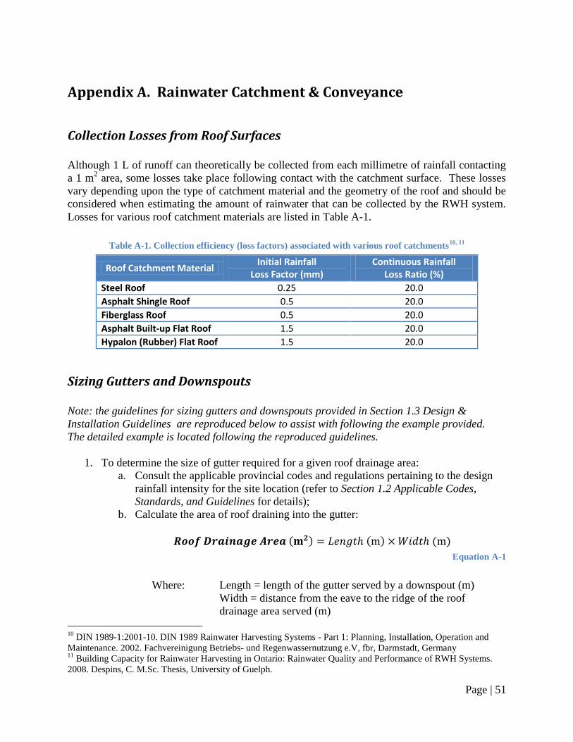
Page | 51
Appendix A. Rainwater Catchment & Conveyance
Collection Losses from Roof Surfaces
Although 1 L of runoff can theoretically be collected from each millimetre of rainfall contacting
a 1 m2 area, some losses take place following contact with the catchment surface. These losses
vary depending upon the type of catchment material and the geometry of the roof and should be
considered when estimating the amount of rainwater that can be collected by the RWH system.
Losses for various roof catchment materials are listed in Table A-1.
Table A-1. Collection efficiency (loss factors) associated with various roof catchments10, 11
Roof Catchment Material Initial Rainfall
Loss Factor (mm) Continuous Rainfall
Loss Ratio (%)
Steel Roof 0.25 20.0
Asphalt Shingle Roof 0.5 20.0
Fiberglass Roof 0.5 20.0
Asphalt Built-up Flat Roof 1.5 20.0
Hypalon (Rubber) Flat Roof 1.5 20.0
Sizing Gutters and Downspouts
Note: the guidelines for sizing gutters and downspouts provided in Section 1.3 Design &
Installation Guidelines are reproduced below to assist with following the example provided.
The detailed example is located following the reproduced guidelines.
1. To determine the size of gutter required for a given roof drainage area:
a. Consult the applicable provincial codes and regulations pertaining to the design
rainfall intensity for the site location (refer to Section 1.2 Applicable Codes,
Standards, and Guidelines for details);
b. Calculate the area of roof draining into the gutter:
( ) ( ) ( )
Equation A-1
Where: Length = length of the gutter served by a downspout (m)
Width = distance from the eave to the ridge of the roof
drainage area served (m)
10
DIN 1989-1:2001-10. DIN 1989 Rainwater Harvesting Systems - Part 1: Planning, Installation, Operation and
Maintenance. 2002. Fachvereinigung Betriebs- und Regenwassernutzung e.V, fbr, Darmstadt, Germany 11
Building Capacity for Rainwater Harvesting in Ontario: Rainwater Quality and Performance of RWH Systems.
2008. Despins, C. M.Sc. Thesis, University of Guelph.
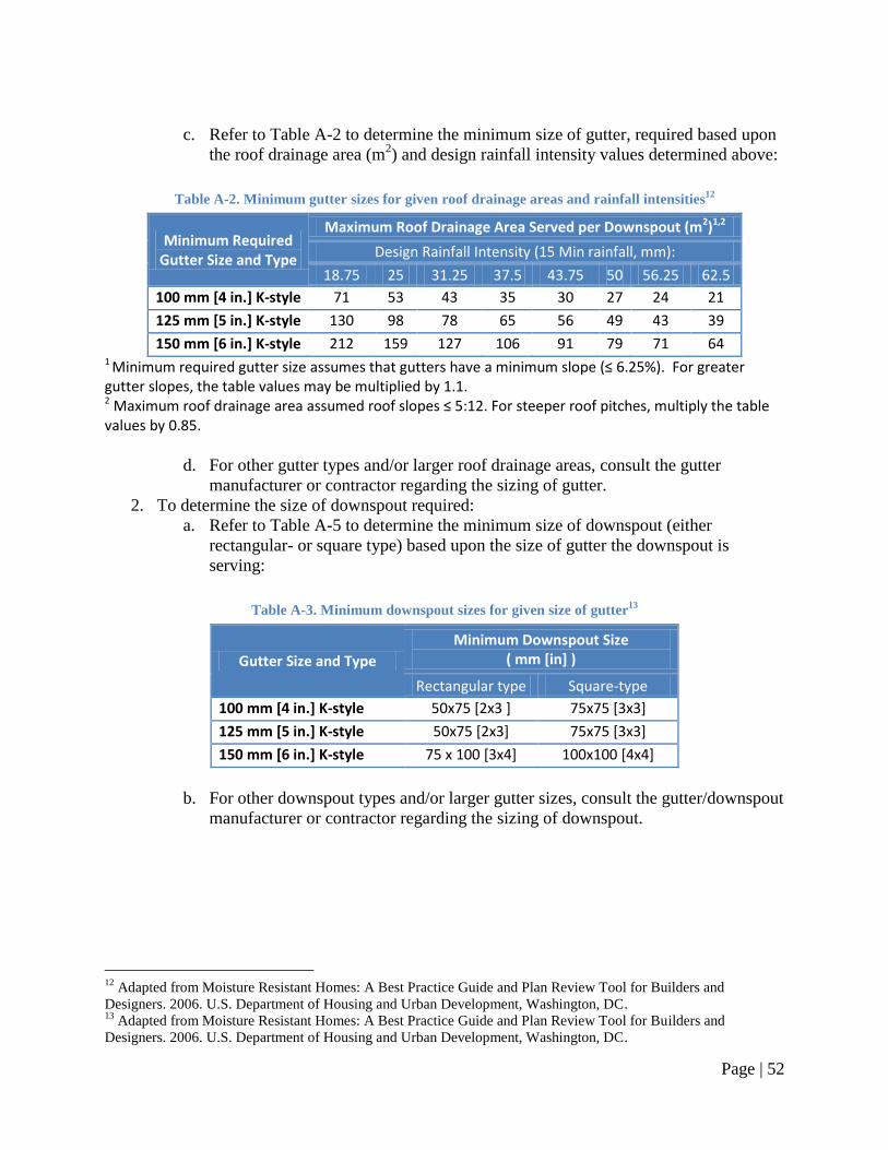
Page | 52
c. Refer to Table A-2 to determine the minimum size of gutter, required based upon
the roof drainage area (m2) and design rainfall intensity values determined above:
Table A-2. Minimum gutter sizes for given roof drainage areas and rainfall intensities12
Minimum Required Gutter Size and Type
Maximum Roof Drainage Area Served per Downspout (m2)1,2
Design Rainfall Intensity (15 Min rainfall, mm):
18.75 25 31.25 37.5 43.75 50 56.25 62.5
100 mm [4 in.] K-style 71 53 43 35 30 27 24 21
125 mm [5 in.] K-style 130 98 78 65 56 49 43 39
150 mm [6 in.] K-style 212 159 127 106 91 79 71 64 1 Minimum required gutter size assumes that gutters have a minimum slope (≤ 6.25%). For greater gutter slopes, the table values may be multiplied by 1.1. 2 Maximum roof drainage area assumed roof slopes ≤ 5:12. For steeper roof pitches, multiply the table values by 0.85.
d. For other gutter types and/or larger roof drainage areas, consult the gutter
manufacturer or contractor regarding the sizing of gutter.
2. To determine the size of downspout required:
a. Refer to Table A-5 to determine the minimum size of downspout (either
rectangular- or square type) based upon the size of gutter the downspout is
serving:
Table A-3. Minimum downspout sizes for given size of gutter13
Gutter Size and Type
Minimum Downspout Size ( mm [in] )
Rectangular type Square-type
100 mm [4 in.] K-style 50x75 [2x3 ] 75x75 [3x3]
125 mm [5 in.] K-style 50x75 [2x3] 75x75 [3x3]
150 mm [6 in.] K-style 75 x 100 [3x4] 100x100 [4x4]
b. For other downspout types and/or larger gutter sizes, consult the gutter/downspout
manufacturer or contractor regarding the sizing of downspout.
12
Adapted from Moisture Resistant Homes: A Best Practice Guide and Plan Review Tool for Builders and
Designers. 2006. U.S. Department of Housing and Urban Development, Washington, DC. 13
Adapted from Moisture Resistant Homes: A Best Practice Guide and Plan Review Tool for Builders and
Designers. 2006. U.S. Department of Housing and Urban Development, Washington, DC.
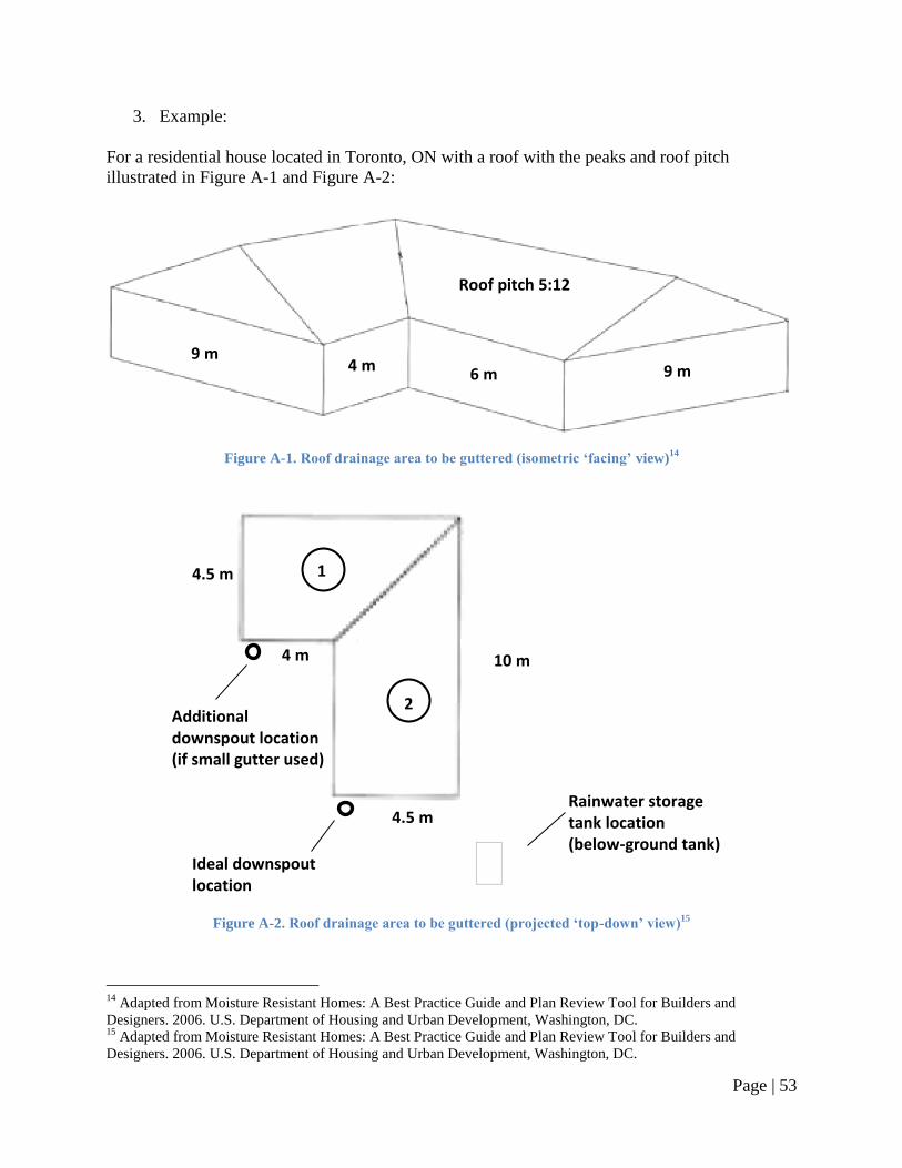
Page | 53
3. Example:
For a residential house located in Toronto, ON with a roof with the peaks and roof pitch
illustrated in Figure A-1 and Figure A-2:
Figure A-1. Roof drainage area to be guttered (isometric ‘facing’ view)
14
Figure A-2. Roof drainage area to be guttered (projected ‘top-down’ view)
15
14
Adapted from Moisture Resistant Homes: A Best Practice Guide and Plan Review Tool for Builders and
Designers. 2006. U.S. Department of Housing and Urban Development, Washington, DC. 15
Adapted from Moisture Resistant Homes: A Best Practice Guide and Plan Review Tool for Builders and
Designers. 2006. U.S. Department of Housing and Urban Development, Washington, DC.
9 m 4 m
6 m 9 m
Roof pitch 5:12
1
2
10 m
4.5 m
4 m
4.5 m
Rainwater storage tank location (below-ground tank)
Ideal downspout location
Additional downspout location (if small gutter used)
Page | 54
From the 2006 edition of Ontario‘s Building Code, Supplementary Standard SB-1, Table 1.2
(refer to Section 1.2 Applicable Codes, Standards, and Guidelines for details):
Design rainfall intensity (15 Min rainfall, mm): 25
To calculate the roof drainage area:
Referring to Table A-2 (reproduced from Table 1-2), the maximum roof drainage area for this
section of roof is given in the second column (25 mm rainfall intensity for the City of Toronto).
To discharge the entire roof drainage area to one downspout:
Referring to the second column of Table A-2, a 100 mm [4 in.] K-style gutter can only be
used to convey rainwater from roof areas of up to 53 m2. This area, however, is less than
the drainage area calculated for this residential household – 63 m2.
By selecting a larger gutter – a 125 mm [5 in.] K-style gutter – all of the drainage area
can be discharged to one downspout as this gutter size can convey rainwater from an area
of up to 78 m2 (> 63 m
2).
Referring to Table A-3 (reproduced from Table 1-3), a 125 mm [5 in.] K-style gutter
requires a 50x75 mm [2x3 in.] rectangular-type downspout, or a 75x75 mm [3x3 in.]
square-type downspout.
To minimize the length of conveyance drainage piping required, the downspout should be
located as close as possible to the rainwater storage tank. The ideal location of the
downspout is illustrated in Figure A-2.
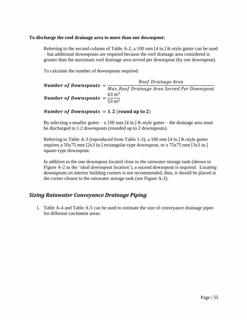
Page | 55
To discharge the roof drainage area to more than one downspout:
Referring to the second column of Table A-2, a 100 mm [4 in.] K-style gutter can be used
– but additional downspouts are required because the roof drainage area considered is
greater than the maximum roof drainage area served per downspout (by one downspout).
To calculate the number of downspouts required:
( )
By selecting a smaller gutter – a 100 mm [4 in.] K-style gutter – the drainage area must
be discharged to 1.2 downspouts (rounded up to 2 downspouts).
Referring to Table A-3 (reproduced from Table 1-3), a 100 mm [4 in.] K-style gutter
requires a 50x75 mm [2x3 in.] rectangular-type downspout, or a 75x75 mm [3x3 in.]
square-type downspout.
In addition to the one downspout located close to the rainwater storage tank (shown in
Figure A-2 as the ‗ideal downspout location‘), a second downspout is required. Locating
downspouts on interior building corners is not recommended, thus, it should be placed at
the corner closest to the rainwater storage tank (see Figure A-2).
Sizing Rainwater Conveyance Drainage Piping
1. Table A-4 and Table A-5 can be used to estimate the size of conveyance drainage pipes
for different catchment areas:
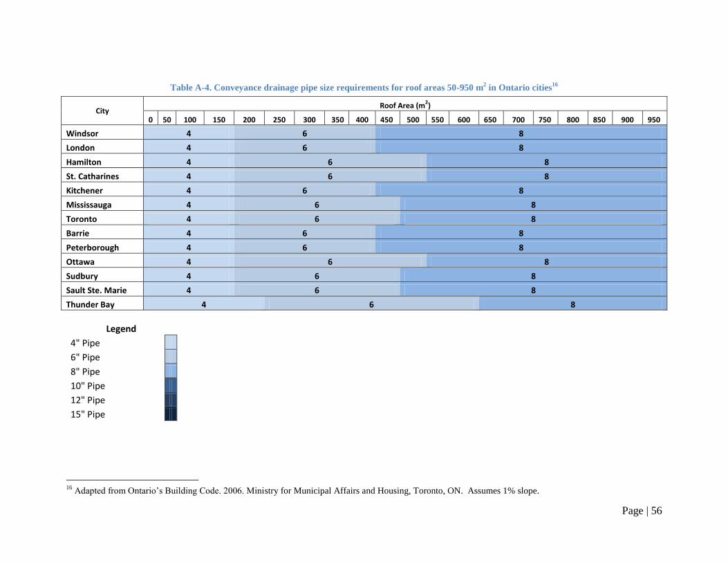
Page | 56
Table A-4. Conveyance drainage pipe size requirements for roof areas 50-950 m2 in Ontario cities
16
City Roof Area (m
2)
0 50 100 150 200 250 300 350 400 450 500 550 600 650 700 750 800 850 900 950
Windsor 4 6 8
London 4 6 8
Hamilton 4 6 8
St. Catharines 4 6 8
Kitchener 4 6 8
Mississauga 4 6 8
Toronto 4 6 8
Barrie 4 6 8
Peterborough 4 6 8
Ottawa 4 6 8
Sudbury 4 6 8
Sault Ste. Marie 4 6 8
Thunder Bay 4 6 8
Legend
4" Pipe
6" Pipe
8" Pipe
10" Pipe
12" Pipe
15" Pipe
16
Adapted from Ontario‘s Building Code. 2006. Ministry for Municipal Affairs and Housing, Toronto, ON. Assumes 1% slope.
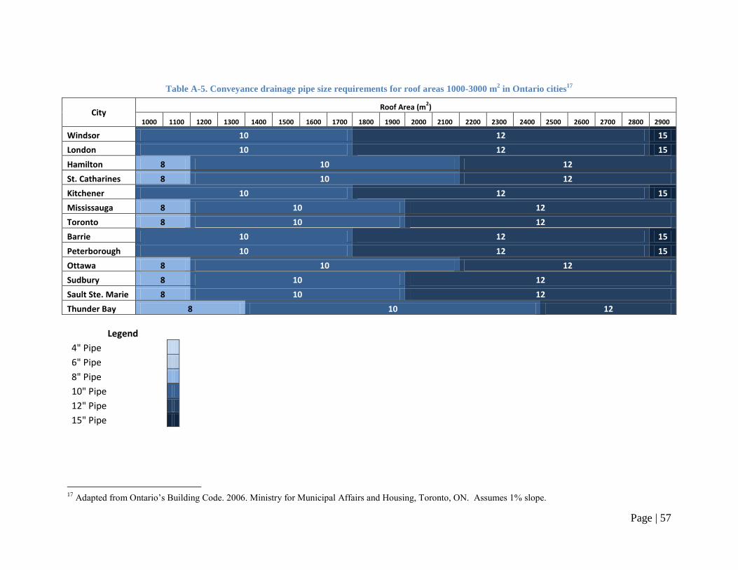
Page | 57
Table A-5. Conveyance drainage pipe size requirements for roof areas 1000-3000 m2 in Ontario cities
17
City Roof Area (m
2)
1000 1100 1200 1300 1400 1500 1600 1700 1800 1900 2000 2100 2200 2300 2400 2500 2600 2700 2800 2900
Windsor 10 12 15
London 10 12 15
Hamilton 8 10 12
St. Catharines 8 10 12
Kitchener 10 12 15
Mississauga 8 10 12
Toronto 8 10 12
Barrie 10 12 15
Peterborough 10 12 15
Ottawa 8 10 12
Sudbury 8 10 12
Sault Ste. Marie 8 10 12
Thunder Bay 8 10 12
Legend
4" Pipe
6" Pipe
8" Pipe
10" Pipe
12" Pipe
15" Pipe
17
Adapted from Ontario‘s Building Code. 2006. Ministry for Municipal Affairs and Housing, Toronto, ON. Assumes 1% slope.
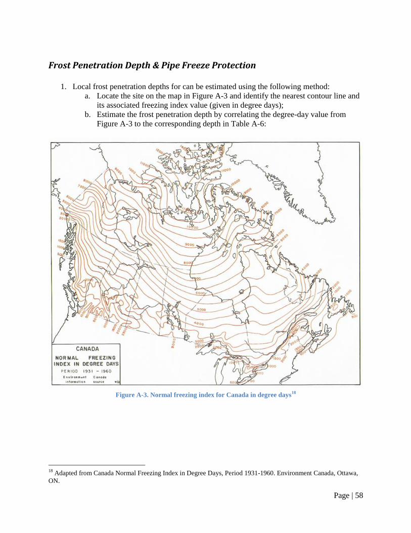
Page | 58
Frost Penetration Depth & Pipe Freeze Protection
1. Local frost penetration depths for can be estimated using the following method:
a. Locate the site on the map in Figure A-3 and identify the nearest contour line and
its associated freezing index value (given in degree days);
b. Estimate the frost penetration depth by correlating the degree-day value from
Figure A-3 to the corresponding depth in Table A-6:
Figure A-3. Normal freezing index for Canada in degree days
18
18
Adapted from Canada Normal Freezing Index in Degree Days, Period 1931-1960. Environment Canada, Ottawa,
ON.
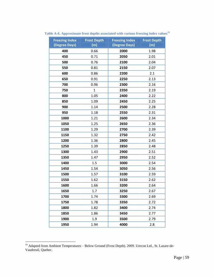
Page | 59
Table A-6. Approximate frost depths associated with various freezing index values19
Freezing Index (Degree Days)
Frost Depth (m)
Freezing Index (Degree Days)
Frost Depth (m)
400 0.66 2000 1.98
450 0.71 2050 2.01
500 0.76 2100 2.04
550 0.81 2150 2.07
600 0.86 2200 2.1
650 0.91 2250 2.13
700 0.96 2300 2.16
750 1 2350 2.19
800 1.05 2400 2.22
850 1.09 2450 2.25
900 1.14 2500 2.28
950 1.18 2550 2.31
1000 1.21 2600 2.34
1050 1.25 2650 2.36
1100 1.29 2700 2.39
1150 1.32 2750 2.42
1200 1.36 2800 2.45
1250 1.39 2850 2.48
1300 1.43 2900 2.51
1350 1.47 2950 2.52
1400 1.5 3000 2.54
1450 1.54 3050 2.56
1500 1.57 3100 2.59
1550 1.62 3150 2.62
1600 1.66 3200 2.64
1650 1.7 3250 2.67
1700 1.74 3300 2.69
1750 1.78 3350 2.72
1800 1.82 3400 2.74
1850 1.86 3450 2.77
1900 1.9 3500 2.79
1950 1.94 4000 2.8
19
Adapted from Ambient Temperatures – Below Ground (Frost Depth). 2009. Urecon Ltd., St. Lazare-de-
Vaudreuil, Quebec.
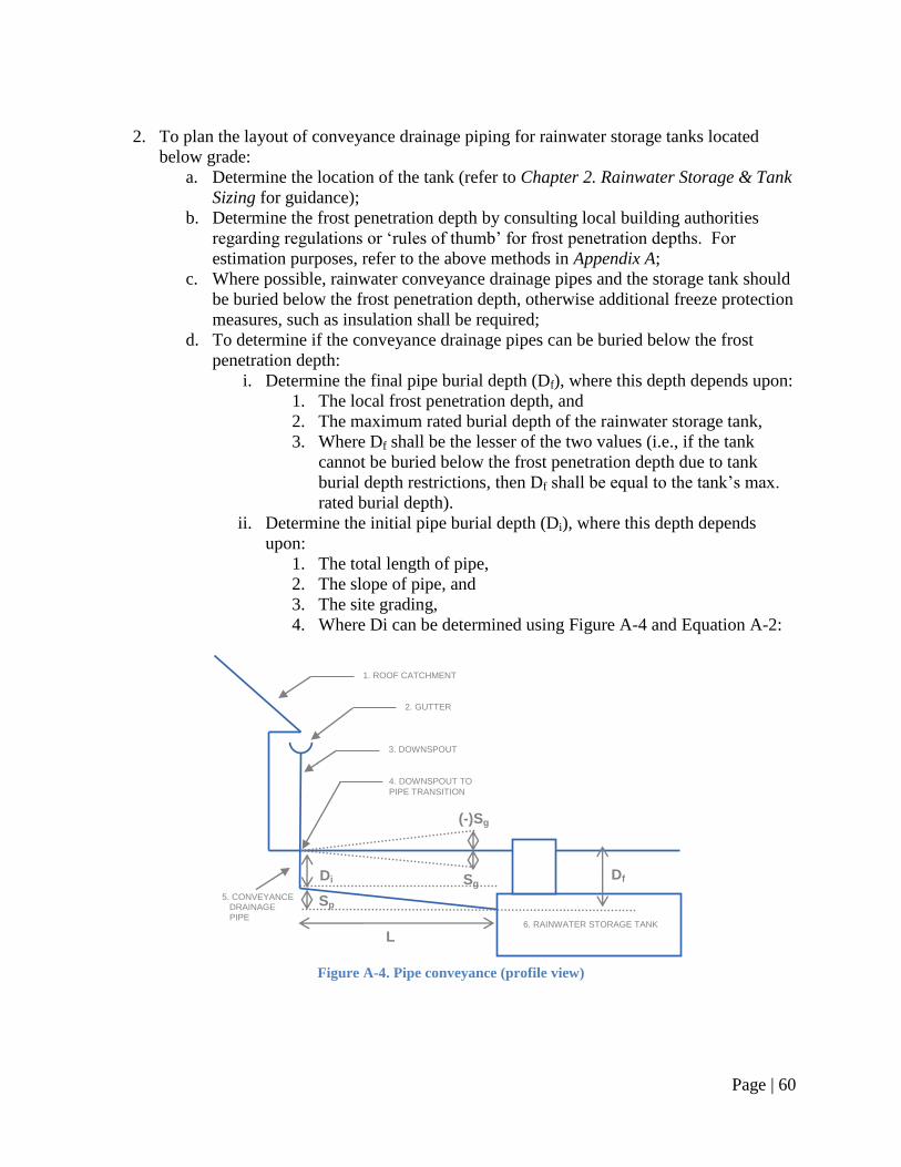
Page | 60
2. To plan the layout of conveyance drainage piping for rainwater storage tanks located
below grade:
a. Determine the location of the tank (refer to Chapter 2. Rainwater Storage & Tank
Sizing for guidance);
b. Determine the frost penetration depth by consulting local building authorities
regarding regulations or ‗rules of thumb‘ for frost penetration depths. For
estimation purposes, refer to the above methods in Appendix A;
c. Where possible, rainwater conveyance drainage pipes and the storage tank should
be buried below the frost penetration depth, otherwise additional freeze protection
measures, such as insulation shall be required;
d. To determine if the conveyance drainage pipes can be buried below the frost
penetration depth:
i. Determine the final pipe burial depth (Df), where this depth depends upon:
1. The local frost penetration depth, and
2. The maximum rated burial depth of the rainwater storage tank,
3. Where Df shall be the lesser of the two values (i.e., if the tank
cannot be buried below the frost penetration depth due to tank
burial depth restrictions, then Df shall be equal to the tank‘s max.
rated burial depth).
ii. Determine the initial pipe burial depth (Di), where this depth depends
upon:
1. The total length of pipe,
2. The slope of pipe, and
3. The site grading,
4. Where Di can be determined using Figure A-4 and Equation A-2:
Figure A-4. Pipe conveyance (profile view)
1. ROOF CATCHMENT
Di
6. RAINWATER STORAGE TANK
L
Sp
Sg
(-)Sg
2. GUTTER
3. DOWNSPOUT
4. DOWNSPOUT TO
PIPE TRANSITION
5. CONVEYANCE DRAINAGE PIPE
Df
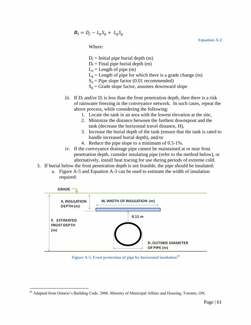
Page | 61
Equation A-2
Where:
Di = Initial pipe burial depth (m)
Df = Final pipe burial depth (m)
Lp = Length of pipe (m)
Lg = Length of pipe for which there is a grade change (m)
Sp = Pipe slope factor (0.01 recommended)
Sg = Grade slope factor, assumes downward slope
iii. If Df and/or Di is less than the frost penetration depth, then there is a risk
of rainwater freezing in the conveyance network. In such cases, repeat the
above process, while considering the following:
1. Locate the tank in an area with the lowest elevation at the site,
2. Minimize the distance between the furthest downspout and the
tank (decrease the horizontal travel distance, H),
3. Increase the burial depth of the tank (ensure that the tank is rated to
handle increased burial depth), and/or
4. Reduce the pipe slope to a minimum of 0.5-1%.
iv. If the conveyance drainage pipe cannot be maintained at or near frost
penetration depth, consider insulating pipe (refer to the method below), or
alternatively, install heat tracing for use during periods of extreme cold.
3. If burial below the frost penetration depth is not feasible, the pipe should be insulated:
a. Figure A-5 and Equation A-3 can be used to estimate the width of insulation
required:
Figure A-5. Frost protection of pipe by horizontal insulation
20
20
Adapted from Ontario‘s Building Code. 2006. Ministry of Municipal Affairs and Housing, Toronto, ON.
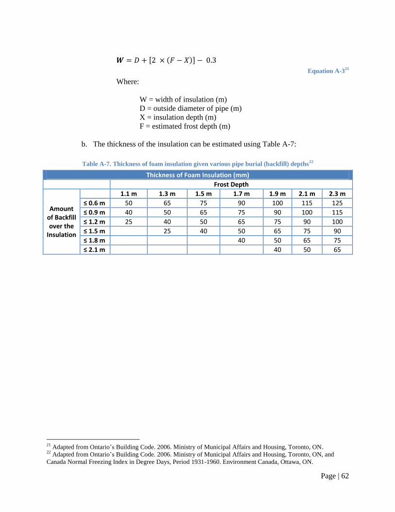
Page | 62
[ ( )]
Equation A-321
Where:
W = width of insulation (m)
D = outside diameter of pipe (m)
X = insulation depth (m)
F = estimated frost depth (m)
b. The thickness of the insulation can be estimated using Table A-7:
Table A-7. Thickness of foam insulation given various pipe burial (backfill) depths22
Thickness of Foam Insulation (mm)
Frost Depth
Amount of Backfill over the
Insulation
1.1 m 1.3 m 1.5 m 1.7 m 1.9 m 2.1 m 2.3 m
≤ 0.6 m 50 65 75 90 100 115 125
≤ 0.9 m 40 50 65 75 90 100 115
≤ 1.2 m 25 40 50 65 75 90 100
≤ 1.5 m 25 40 50 65 75 90
≤ 1.8 m 40 50 65 75
≤ 2.1 m 40 50 65
21
Adapted from Ontario‘s Building Code. 2006. Ministry of Municipal Affairs and Housing, Toronto, ON. 22
Adapted from Ontario‘s Building Code. 2006. Ministry of Municipal Affairs and Housing, Toronto, ON, and
Canada Normal Freezing Index in Degree Days, Period 1931-1960. Environment Canada, Ottawa, ON.
Page | 63
Appendix B. Rainwater Storage & Tank Sizing
Note: Some of the fixtures listed in this Appendix may not be permitted by the applicable
provincial codes and regulations. Data and examples referencing such fixtures are provided for
illustration purposes only.
Rainwater Harvesting Design Tool
1. Rainwater storage tanks can be sized using the Rainwater Harvesting System Design
Tool, which can be accessed on-line;
2. Instructions on the use of the Rainwater Harvesting System Design Tool are provided
with the Design Tool software package. Refer to these instructions for further details.
Rainwater Storage Tank Sizing Table
1. Rainwater storage tanks can be sized using Table B-3, which was developed using the
Rainwater Harvesting System Design Tool. Note: Table B-3 summarizes results from the
tool for the City of Toronto, but these tank sizes should be applicable for much of
southern Ontario. In regions where there is less annual rainfall than Toronto, tanks with
larger storage capacities than those listed in Table B-3 are recommended.
2. Household indoor rainwater demand can be estimated using Table B-1 and the following
instructions:
a. For each fixture to be supplied with rainwater, determine the fixture type and
associated water usage by examining the fixture and/or referring to the
manufacturer‘s product literature;
b. Once the fixture type and water usage have been determined, calculate the daily
rainwater usage for the fixture by multiplying the water usage (provided by the
manufacturer, or using the average figures provided in Table B-1) by the number
of uses per person per day (provided in Table B-1). Multiply the resulting figure
by the number of occupants residing within the household;
c. Sum these values to determine the total indoor rainwater demand (Litres per day);
d. Sum the total indoor rainwater demand with the total outdoor rainwater demand,
where applicable (refer to Table B-2 and the accompanying instructions for
assistance on calculating outdoor rainwater usage);
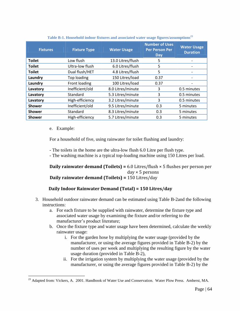
Page | 64
Table B-1. Household indoor fixtures and associated water usage figures/assumptions23
Fixtures Fixture Type Water Usage Number of Uses Per Person Per
Day
Water Usage Duration
Toilet Low flush 13.0 Litres/flush 5 -
Toilet Ultra-low flush 6.0 Litres/flush 5 -
Toilet Dual flush/HET 4.8 Litres/flush 5 -
Laundry Top loading 150 Litres/load 0.37 -
Laundry Front loading 100 Litres/load 0.37 -
Lavatory Inefficient/old 8.0 Litres/minute 3 0.5 minutes
Lavatory Standard 5.3 Litres/minute 3 0.5 minutes
Lavatory High-efficiency 3.2 Litres/minute 3 0.5 minutes
Shower Inefficient/old 9.5 Litres/minute 0.3 5 minutes
Shower Standard 8.3 Litres/minute 0.3 5 minutes
Shower High-efficiency 5.7 Litres/minute 0.3 5 minutes
e. Example:
For a household of five, using rainwater for toilet flushing and laundry:
- The toilets in the home are the ultra-low flush 6.0 Litre per flush type.
- The washing machine is a typical top-loading machine using 150 Litres per load.
Daily rainwater demand (Toilets) = 6.0 Litres/flush × 5 flushes per person per day × 5 persons
Daily rainwater demand (Toilets) = 150 Litres/day Daily Indoor Rainwater Demand (Total) = 150 Litres/day
3. Household outdoor rainwater demand can be estimated using Table B-2and the following
instructions:
a. For each fixture to be supplied with rainwater, determine the fixture type and
associated water usage by examining the fixture and/or referring to the
manufacturer‘s product literature;
b. Once the fixture type and water usage have been determined, calculate the weekly
rainwater usage:
i. For the garden hose by multiplying the water usage (provided by the
manufacturer, or using the average figures provided in Table B-2) by the
number of uses per week and multiplying the resulting figure by the water
usage duration (provided in Table B-2),
ii. For the irrigation system by multiplying the water usage (provided by the
manufacturer, or using the average figures provided in Table B-2) by the
23
Adapted from: Vickers, A. 2001. Handbook of Water Use and Conservation. Water Plow Press. Amherst, MA.
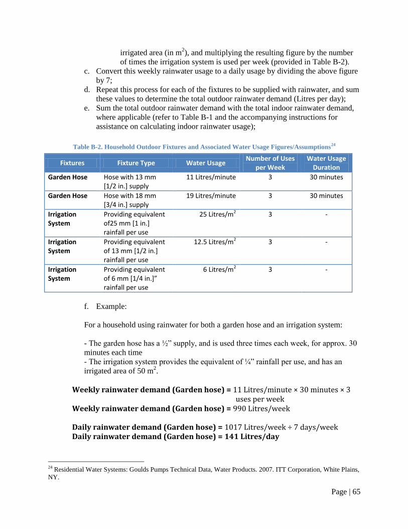
Page | 65
irrigated area (in m2), and multiplying the resulting figure by the number
of times the irrigation system is used per week (provided in Table B-2).
c. Convert this weekly rainwater usage to a daily usage by dividing the above figure
by 7;
d. Repeat this process for each of the fixtures to be supplied with rainwater, and sum
these values to determine the total outdoor rainwater demand (Litres per day);
e. Sum the total outdoor rainwater demand with the total indoor rainwater demand,
where applicable (refer to Table B-1 and the accompanying instructions for
assistance on calculating indoor rainwater usage);
Table B-2. Household Outdoor Fixtures and Associated Water Usage Figures/Assumptions24
Fixtures Fixture Type Water Usage Number of Uses
per Week Water Usage
Duration
Garden Hose Hose with 13 mm [1/2 in.] supply
11 Litres/minute 3 30 minutes
Garden Hose Hose with 18 mm [3/4 in.] supply
19 Litres/minute 3 30 minutes
Irrigation System
Providing equivalent of25 mm [1 in.] rainfall per use
25 Litres/m2 3 -
Irrigation System
Providing equivalent of 13 mm [1/2 in.] rainfall per use
12.5 Litres/m2 3 -
Irrigation System
Providing equivalent of 6 mm [1/4 in.]” rainfall per use
6 Litres/m2 3 -
f. Example:
For a household using rainwater for both a garden hose and an irrigation system:
- The garden hose has a ½‖ supply, and is used three times each week, for approx. 30
minutes each time
- The irrigation system provides the equivalent of ¼‖ rainfall per use, and has an
irrigated area of 50 m2.
Weekly rainwater demand (Garden hose) = 11 Litres/minute × 30 minutes × 3 uses per week
Weekly rainwater demand (Garden hose) = 990 Litres/week
Daily rainwater demand (Garden hose) = 1017 Litres/week ÷ 7 days/week Daily rainwater demand (Garden hose) = 141 Litres/day
24
Residential Water Systems: Goulds Pumps Technical Data, Water Products. 2007. ITT Corporation, White Plains,
NY.
Page | 66
Weekly rainwater demand (Irrigation System) = 6 Litres/m2 × 50 m2 irrigated area × 3 uses per week
Weekly rainwater demand (Irrigation System) = 900 Litres/week
Daily rainwater demand (Irrigation System) = 900 Litres/week ÷ 7 days/week Daily rainwater demand (Irrigation System) = 129 Litres/day
Daily Outdoor Rainwater Demand (Total) = 141 Litres/day + 129 Litres/day Daily Outdoor Rainwater Demand (Total) = 270 Litres/day
4. Calculate the daily rainwater demand (Litres per day) by summing the household indoor
rainwater demand and the outdoor rainwater demand;
a. Example:
Summing indoor & outdoor demand:
Daily Rainwater Demand (Total) = 150 Litres/day + 270 Litres/day Daily Rainwater Demand (Total) = 420 Litres/day
5. Refer to Table B-3 to find the recommended tank size using the daily rainwater demand
(Litres per day) and the roof catchment area (m2);
6. Note: How were Table B-3 recommended storage volumes determined?
a. For each unique combination of daily rainwater demand and roof catchment area
(i.e., for a RWH system with a daily rainwater demand of 50 Litres/day and a roof
catchment area of 100 m2) rainwater storage tanks of increasing storage capacities
were modelled using the Rainwater Harvesting Design Tool;
b. While comparing the multiple tanks, if a tank with a larger storage capacity
provided a significant increase in the water savings provided by the RWH system,
when compared against a smaller tank, the Design Tool recommended the larger
tank.
c. This process was repeated with increasing storage tank volumes until the water
savings increase provided by the larger tank was considered to be insignificant;
d. The criteria that was used to distinguish between a significant and insignificant
was as follows:
i. If larger tank provides ≥ 2.5% increase in water savings per 1,000 Litres,
select larger tank and continue process to examine the water savings of
subsequent larger tanks;
ii. If larger tank provides < 2.5% increase in water savings per 1,000 Litres,
do not consider the tank, and recommend the largest storage tank that met
the ≥ 2.5% criteria.
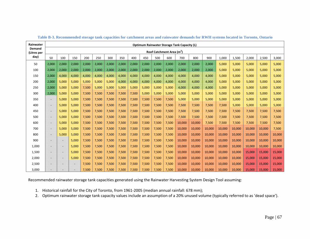
Page | 67
Table B-3. Recommended storage tank capacities for catchment areas and rainwater demands for RWH systems located in Toronto, Ontario
Rainwater Demand
(Litres per day)
Optimum Rainwater Storage Tank Capacity (L)
Roof Catchment Area (m2)
50 100 150 200 250 300 350 400 450 500 600 700 800 900 1,000 1,500 2,000 2,500 3,000
50 2,000 2,000 2,000 2,000 2,000 2,000 2,000 2,000 2,000 2,000 2,000 2,000 2,000 2,000 5,000 5,000 5,000 5,000 5,000
100 2,000 2,000 2,000 2,000 2,000 2,000 2,000 2,000 2,000 2,000 2,000 2,000 2,000 2,000 5,000 5,000 5,000 5,000 5,000
150 2,000 4,000 4,000 4,000 4,000 4,000 4,000 4,000 4,000 4,000 4,000 4,000 4,000 4,000 5,000 5,000 5,000 5,000 5,000
200 2,000 5,000 5,000 5,000 5,000 5,000 4,000 4,000 4,000 4,000 4,000 4,000 4,000 4,000 5,000 5,000 5,000 5,000 5,000
250 2,000 5,000 5,000 7,500 5,000 5,000 5,000 5,000 5,000 5,000 5,000 4,000 4,000 4,000 5,000 5,000 5,000 5,000 5,000
300 2,000 5,000 5,000 7,500 7,500 7,500 7,500 7,500 5,000 5,000 5,000 5,000 5,000 5,000 5,000 5,000 5,000 5,000 5,000
350 - 5,000 5,000 7,500 7,500 7,500 7,500 7,500 7,500 7,500 7,500 5,000 5,000 5,000 5,000 5,000 5,000 5,000 5,000
400 - 5,000 5,000 7,500 7,500 7,500 7,500 7,500 7,500 7,500 7,500 7,500 7,500 7,500 7,500 5,000 5,000 5,000 5,000
450 - 5,000 5,000 7,500 7,500 7,500 7,500 7,500 7,500 7,500 7,500 7,500 7,500 7,500 7,500 7,500 7,500 7,500 7,500
500 - 5,000 5,000 7,500 7,500 7,500 7,500 7,500 7,500 7,500 7,500 7,500 7,500 7,500 7,500 7,500 7,500 7,500 7,500
600 - 5,000 5,000 7,500 7,500 7,500 7,500 7,500 7,500 7,500 7,500 10,000 10,000 7,500 7,500 7,500 7,500 7,500 7,500
700 - 5,000 5,000 7,500 7,500 7,500 7,500 7,500 7,500 7,500 7,500 10,000 10,000 10,000 10,000 10,000 10,000 10,000 7,500
800 - 5,000 5,000 7,500 7,500 7,500 7,500 7,500 7,500 7,500 7,500 10,000 10,000 10,000 10,000 10,000 10,000 10,000 10,000
900 - - 5,000 7,500 7,500 7,500 7,500 7,500 7,500 7,500 7,500 10,000 10,000 10,000 10,000 10,000 10,000 10,000 10,000
1,000 - - 5,000 7,500 7,500 7,500 7,500 7,500 7,500 7,500 7,500 10,000 10,000 10,000 10,000 10,000 10,000 10,000 10,000
1,500 - - 5,000 7,500 7,500 7,500 7,500 7,500 7,500 7,500 7,500 10,000 10,000 10,000 10,000 10,000 15,000 15,000 15,000
2,000 - - 5,000 7,500 7,500 7,500 7,500 7,500 7,500 7,500 7,500 10,000 10,000 10,000 10,000 10,000 15,000 15,000 15,000
2,500 - - - 7,500 7,500 7,500 7,500 7,500 7,500 7,500 7,500 10,000 10,000 10,000 10,000 10,000 15,000 15,000 15,000
3,000 - - - 7,500 7,500 7,500 7,500 7,500 7,500 7,500 7,500 10,000 10,000 10,000 10,000 10,000 15,000 15,000 15,000
Recommended rainwater storage tank capacities generated using the Rainwater Harvesting System Design Tool assuming:
1. Historical rainfall for the City of Toronto, from 1961-2005 (median annual rainfall: 678 mm); 2. Optimum rainwater storage tank capacity values include an assumption of a 20% unused volume (typically referred to as ‘dead space’).
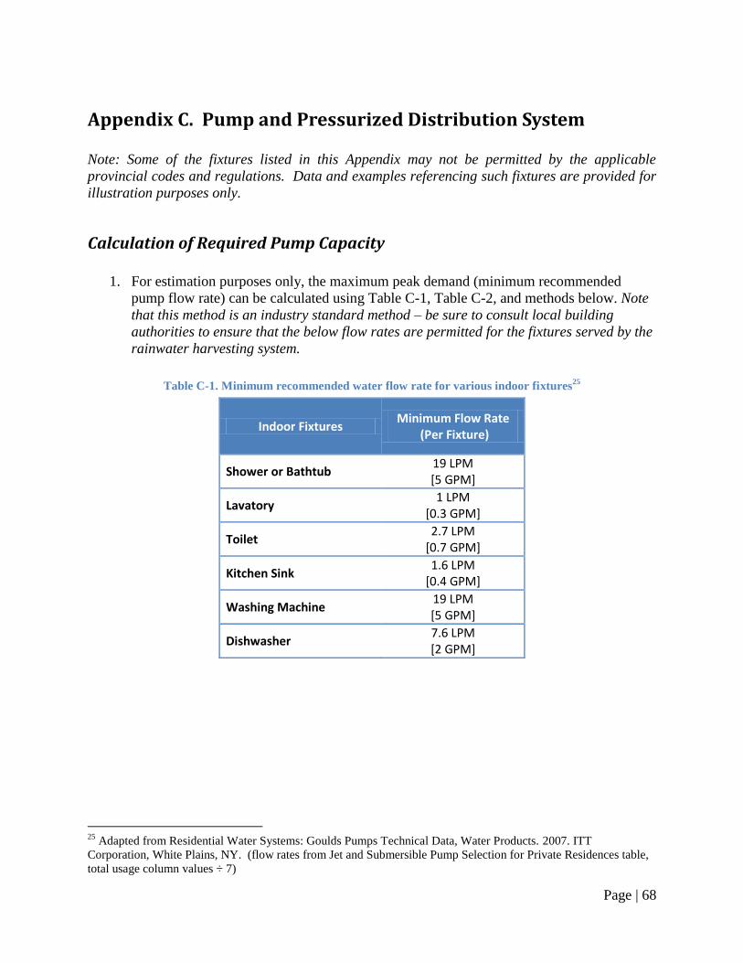
Page | 68
Appendix C. Pump and Pressurized Distribution System
Note: Some of the fixtures listed in this Appendix may not be permitted by the applicable
provincial codes and regulations. Data and examples referencing such fixtures are provided for
illustration purposes only.
Calculation of Required Pump Capacity
1. For estimation purposes only, the maximum peak demand (minimum recommended
pump flow rate) can be calculated using Table C-1, Table C-2, and methods below. Note
that this method is an industry standard method – be sure to consult local building
authorities to ensure that the below flow rates are permitted for the fixtures served by the
rainwater harvesting system.
Table C-1. Minimum recommended water flow rate for various indoor fixtures25
Indoor Fixtures Minimum Flow Rate
(Per Fixture)
Shower or Bathtub 19 LPM [5 GPM]
Lavatory 1 LPM
[0.3 GPM]
Toilet 2.7 LPM
[0.7 GPM]
Kitchen Sink 1.6 LPM
[0.4 GPM]
Washing Machine 19 LPM [5 GPM]
Dishwasher 7.6 LPM [2 GPM]
25
Adapted from Residential Water Systems: Goulds Pumps Technical Data, Water Products. 2007. ITT
Corporation, White Plains, NY. (flow rates from Jet and Submersible Pump Selection for Private Residences table,
total usage column values ÷ 7)
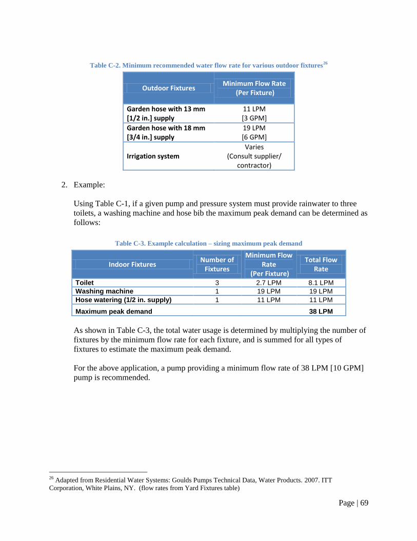
Page | 69
Table C-2. Minimum recommended water flow rate for various outdoor fixtures26
Outdoor Fixtures Minimum Flow Rate
(Per Fixture)
Garden hose with 13 mm [1/2 in.] supply
11 LPM [3 GPM]
Garden hose with 18 mm [3/4 in.] supply
19 LPM [6 GPM]
Irrigation system Varies
(Consult supplier/ contractor)
2. Example:
Using Table C-1, if a given pump and pressure system must provide rainwater to three
toilets, a washing machine and hose bib the maximum peak demand can be determined as
follows:
Table C-3. Example calculation – sizing maximum peak demand
Indoor Fixtures Number of
Fixtures
Minimum Flow Rate
(Per Fixture)
Total Flow Rate
Toilet 3 2.7 LPM 8.1 LPM
Washing machine 1 19 LPM 19 LPM
Hose watering (1/2 in. supply) 1 11 LPM 11 LPM
Maximum peak demand 38 LPM
As shown in Table C-3, the total water usage is determined by multiplying the number of
fixtures by the minimum flow rate for each fixture, and is summed for all types of
fixtures to estimate the maximum peak demand.
For the above application, a pump providing a minimum flow rate of 38 LPM [10 GPM]
pump is recommended.
26
Adapted from Residential Water Systems: Goulds Pumps Technical Data, Water Products. 2007. ITT
Corporation, White Plains, NY. (flow rates from Yard Fixtures table)
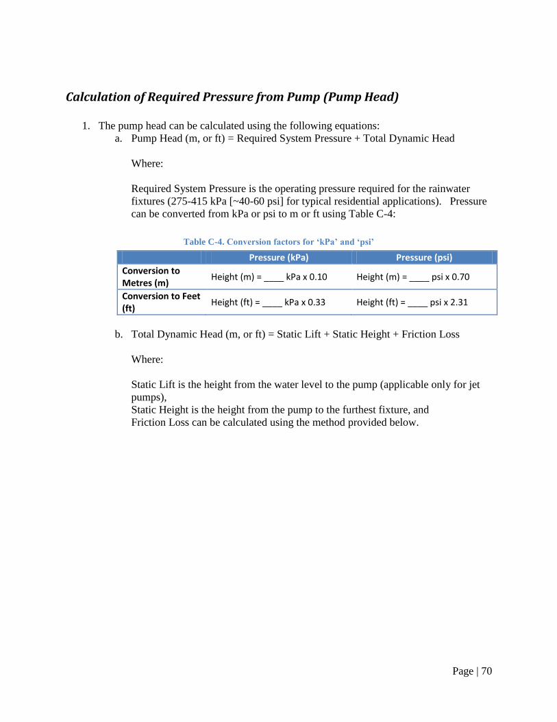
Page | 70
Calculation of Required Pressure from Pump (Pump Head)
1. The pump head can be calculated using the following equations:
a. Pump Head (m, or ft) = Required System Pressure + Total Dynamic Head
Where:
Required System Pressure is the operating pressure required for the rainwater
fixtures (275-415 kPa [~40-60 psi] for typical residential applications). Pressure
can be converted from kPa or psi to m or ft using Table C-4:
Table C-4. Conversion factors for ‘kPa’ and ‘psi’
Pressure (kPa) Pressure (psi)
Conversion to Metres (m)
Height (m) = ____ kPa x 0.10 Height (m) = ____ psi x 0.70
Conversion to Feet (ft)
Height (ft) = ____ kPa x 0.33 Height (ft) = ____ psi x 2.31
b. Total Dynamic Head (m, or ft) = Static Lift + Static Height + Friction Loss
Where:
Static Lift is the height from the water level to the pump (applicable only for jet
pumps),
Static Height is the height from the pump to the furthest fixture, and
Friction Loss can be calculated using the method provided below.
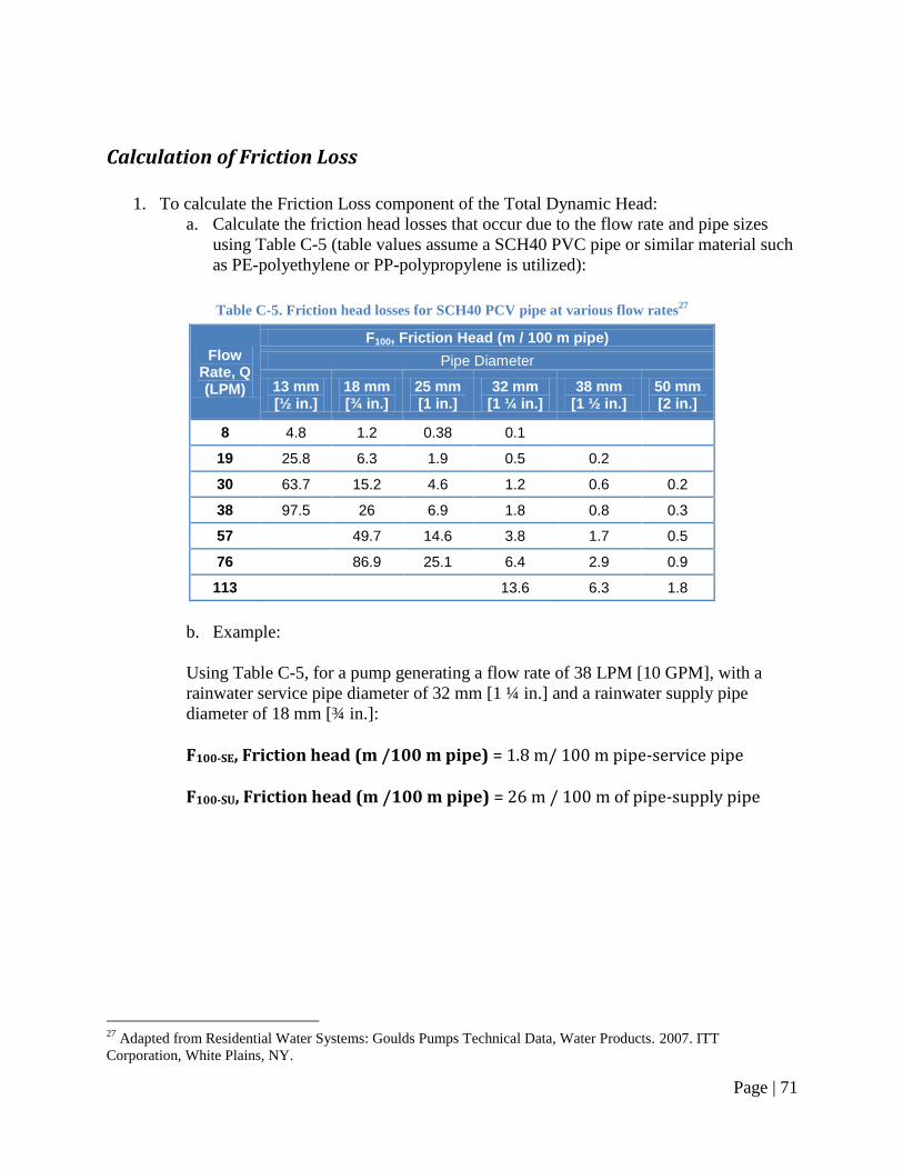
Page | 71
Calculation of Friction Loss
1. To calculate the Friction Loss component of the Total Dynamic Head:
a. Calculate the friction head losses that occur due to the flow rate and pipe sizes
using Table C-5 (table values assume a SCH40 PVC pipe or similar material such
as PE-polyethylene or PP-polypropylene is utilized):
Table C-5. Friction head losses for SCH40 PCV pipe at various flow rates27
Flow Rate, Q (LPM)
F100, Friction Head (m / 100 m pipe)
Pipe Diameter
13 mm [½ in.]
18 mm [¾ in.]
25 mm [1 in.]
32 mm [1 ¼ in.]
38 mm [1 ½ in.]
50 mm [2 in.]
8 4.8 1.2 0.38 0.1
19 25.8 6.3 1.9 0.5 0.2
30 63.7 15.2 4.6 1.2 0.6 0.2
38 97.5 26 6.9 1.8 0.8 0.3
57 49.7 14.6 3.8 1.7 0.5
76 86.9 25.1 6.4 2.9 0.9
113 13.6 6.3 1.8
b. Example:
Using Table C-5, for a pump generating a flow rate of 38 LPM [10 GPM], with a
rainwater service pipe diameter of 32 mm [1 ¼ in.] and a rainwater supply pipe
diameter of 18 mm [¾ in.]:
F100-SE, Friction head (m /100 m pipe) = 1.8 m/ 100 m pipe-service pipe F100-SU, Friction head (m /100 m pipe) = 26 m / 100 m of pipe-supply pipe
27
Adapted from Residential Water Systems: Goulds Pumps Technical Data, Water Products. 2007. ITT
Corporation, White Plains, NY.
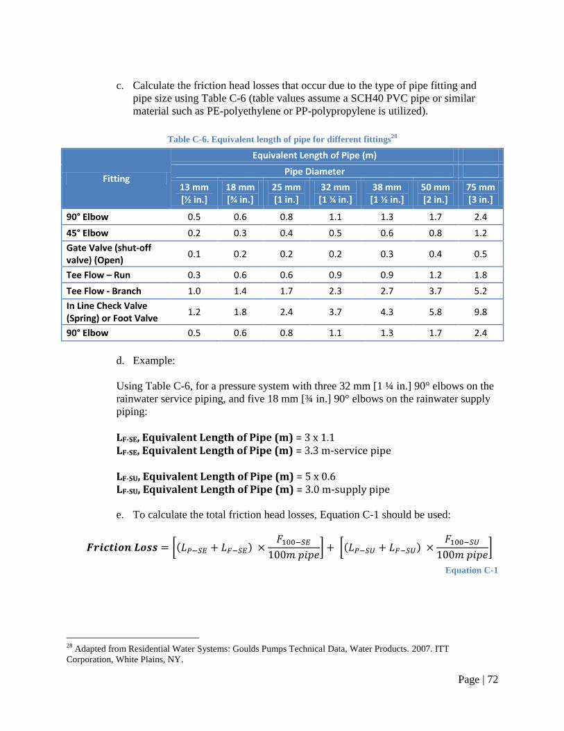
Page | 72
c. Calculate the friction head losses that occur due to the type of pipe fitting and
pipe size using Table C-6 (table values assume a SCH40 PVC pipe or similar
material such as PE-polyethylene or PP-polypropylene is utilized).
Table C-6. Equivalent length of pipe for different fittings28
Fitting
Equivalent Length of Pipe (m)
Pipe Diameter
13 mm [½ in.]
18 mm [¾ in.]
25 mm [1 in.]
32 mm [1 ¼ in.]
38 mm [1 ½ in.]
50 mm [2 in.]
75 mm [3 in.]
90° Elbow 0.5 0.6 0.8 1.1 1.3 1.7 2.4
45° Elbow 0.2 0.3 0.4 0.5 0.6 0.8 1.2
Gate Valve (shut-off valve) (Open)
0.1 0.2 0.2 0.2 0.3 0.4 0.5
Tee Flow – Run 0.3 0.6 0.6 0.9 0.9 1.2 1.8
Tee Flow - Branch 1.0 1.4 1.7 2.3 2.7 3.7 5.2
In Line Check Valve (Spring) or Foot Valve
1.2 1.8 2.4 3.7 4.3 5.8 9.8
90° Elbow 0.5 0.6 0.8 1.1 1.3 1.7 2.4
d. Example:
Using Table C-6, for a pressure system with three 32 mm [1 ¼ in.] 90° elbows on the
rainwater service piping, and five 18 mm [¾ in.] 90° elbows on the rainwater supply
piping:
LF-SE, Equivalent Length of Pipe (m) = 3 x 1.1 LF-SE, Equivalent Length of Pipe (m) = 3.3 m-service pipe LF-SU, Equivalent Length of Pipe (m) = 5 x 0.6 LF-SU, Equivalent Length of Pipe (m) = 3.0 m-supply pipe
e. To calculate the total friction head losses, Equation C-1 should be used:
[( )
] [( )
]
Equation C-1
28
Adapted from Residential Water Systems: Goulds Pumps Technical Data, Water Products. 2007. ITT
Corporation, White Plains, NY.
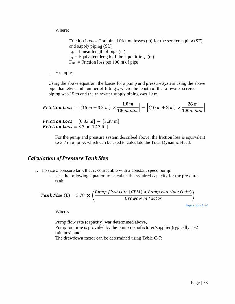
Page | 73
Where:
Friction Loss = Combined friction losses (m) for the service piping (SE)
and supply piping (SU)
LP = Linear length of pipe (m)
LF = Equivalent length of the pipe fittings (m)
F100 = Friction loss per 100 m of pipe
f. Example:
Using the above equation, the losses for a pump and pressure system using the above
pipe diameters and number of fittings, where the length of the rainwater service
piping was 15 m and the rainwater supply piping was 10 m:
[( )
] [( )
]
[ ] [ ] [ ]
For the pump and pressure system described above, the friction loss is equivalent
to 3.7 m of pipe, which can be used to calculate the Total Dynamic Head.
Calculation of Pressure Tank Size
1. To size a pressure tank that is compatible with a constant speed pump:
a. Use the following equation to calculate the required capacity for the pressure
tank:
( ) ( ( ) ( )
)
Equation C-2
Where:
Pump flow rate (capacity) was determined above,
Pump run time is provided by the pump manufacturer/supplier (typically, 1-2
minutes), and
The drawdown factor can be determined using Table C-7:
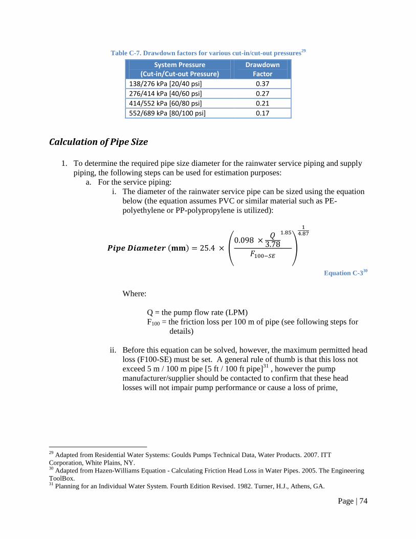
Page | 74
Table C-7. Drawdown factors for various cut-in/cut-out pressures29
System Pressure (Cut-in/Cut-out Pressure)
Drawdown Factor
138/276 kPa [20/40 psi] 0.37
276/414 kPa [40/60 psi] 0.27
414/552 kPa [60/80 psi] 0.21
552/689 kPa [80/100 psi] 0.17
Calculation of Pipe Size
1. To determine the required pipe size diameter for the rainwater service piping and supply
piping, the following steps can be used for estimation purposes:
a. For the service piping:
i. The diameter of the rainwater service pipe can be sized using the equation
below (the equation assumes PVC or similar material such as PE-
polyethylene or PP-polypropylene is utilized):
( ) (
)
Equation C-330
Where:
Q = the pump flow rate (LPM)
F100 = the friction loss per 100 m of pipe (see following steps for
details)
ii. Before this equation can be solved, however, the maximum permitted head
loss (F100-SE) must be set. A general rule of thumb is that this loss not
exceed 5 m / 100 m pipe [5 ft / 100 ft pipe]31
, however the pump
manufacturer/supplier should be contacted to confirm that these head
losses will not impair pump performance or cause a loss of prime,
29
Adapted from Residential Water Systems: Goulds Pumps Technical Data, Water Products. 2007. ITT
Corporation, White Plains, NY. 30
Adapted from Hazen-Williams Equation - Calculating Friction Head Loss in Water Pipes. 2005. The Engineering
ToolBox. 31
Planning for an Individual Water System. Fourth Edition Revised. 1982. Turner, H.J., Athens, GA.
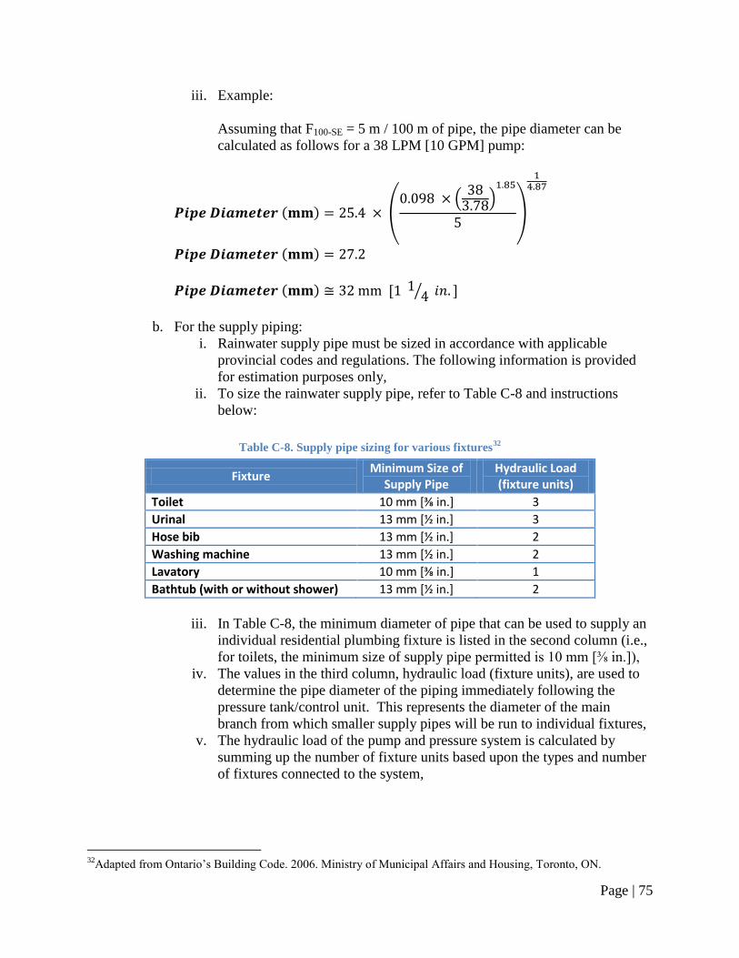
Page | 75
iii. Example:
Assuming that F100-SE = 5 m / 100 m of pipe, the pipe diameter can be
calculated as follows for a 38 LPM [10 GPM] pump:
( ) ( (
)
)
( )
( ) [ ⁄ ]
b. For the supply piping:
i. Rainwater supply pipe must be sized in accordance with applicable
provincial codes and regulations. The following information is provided
for estimation purposes only,
ii. To size the rainwater supply pipe, refer to Table C-8 and instructions
below:
Table C-8. Supply pipe sizing for various fixtures32
Fixture Minimum Size of
Supply Pipe Hydraulic Load (fixture units)
Toilet 10 mm *⅜ in.+ 3 Urinal 13 mm [½ in.] 3 Hose bib 13 mm [½ in.] 2 Washing machine 13 mm [½ in.] 2 Lavatory 10 mm *⅜ in.+ 1 Bathtub (with or without shower) 13 mm [½ in.] 2
iii. In Table C-8, the minimum diameter of pipe that can be used to supply an
individual residential plumbing fixture is listed in the second column (i.e.,
for toilets, the minimum size of supply pipe permitted is 10 mm [⅜ in.]),
iv. The values in the third column, hydraulic load (fixture units), are used to
determine the pipe diameter of the piping immediately following the
pressure tank/control unit. This represents the diameter of the main
branch from which smaller supply pipes will be run to individual fixtures,
v. The hydraulic load of the pump and pressure system is calculated by
summing up the number of fixture units based upon the types and number
of fixtures connected to the system,
32
Adapted from Ontario‘s Building Code. 2006. Ministry of Municipal Affairs and Housing, Toronto, ON.
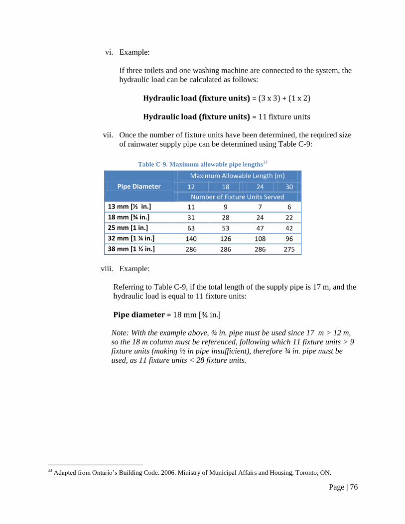
Page | 76
vi. Example:
If three toilets and one washing machine are connected to the system, the
hydraulic load can be calculated as follows:
Hydraulic load (fixture units) = (3 x 3) + (1 x 2) Hydraulic load (fixture units) = 11 fixture units
vii. Once the number of fixture units have been determined, the required size
of rainwater supply pipe can be determined using Table C-9:
Table C-9. Maximum allowable pipe lengths33
Pipe Diameter
Maximum Allowable Length (m)
12 18 24 30
Number of Fixture Units Served 13 mm [½ in.] 11 9 7 6
18 mm [¾ in.] 31 28 24 22
25 mm [1 in.] 63 53 47 42
32 mm [1 ¼ in.] 140 126 108 96
38 mm [1 ½ in.] 286 286 286 275
viii. Example:
Referring to Table C-9, if the total length of the supply pipe is 17 m, and the
hydraulic load is equal to 11 fixture units:
Pipe diameter = 18 mm [¾ in.]
Note: With the example above, ¾ in. pipe must be used since 17 m > 12 m,
so the 18 m column must be referenced, following which 11 fixture units > 9
fixture units (making ½ in pipe insufficient), therefore ¾ in. pipe must be
used, as 11 fixture units < 28 fixture units.
33
Adapted from Ontario‘s Building Code. 2006. Ministry of Municipal Affairs and Housing, Toronto, ON.
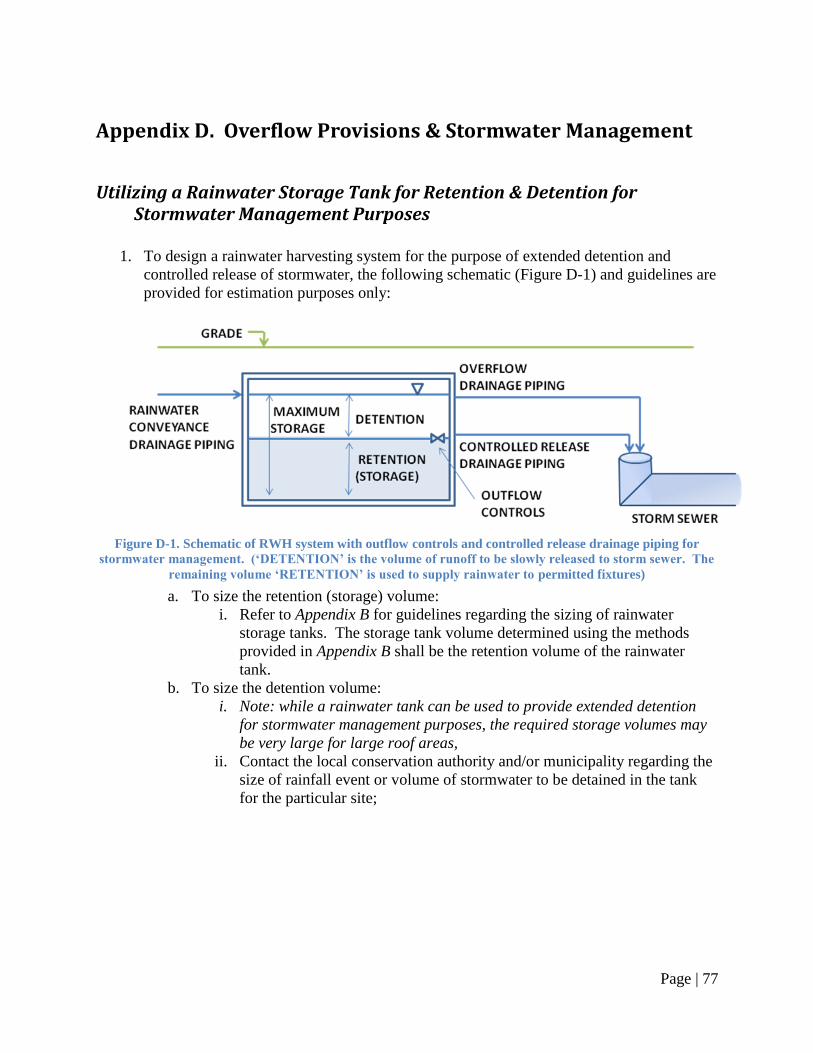
Page | 77
Appendix D. Overflow Provisions & Stormwater Management
Utilizing a Rainwater Storage Tank for Retention & Detention for Stormwater Management Purposes
1. To design a rainwater harvesting system for the purpose of extended detention and
controlled release of stormwater, the following schematic (Figure D-1) and guidelines are
provided for estimation purposes only:
Figure D-1. Schematic of RWH system with outflow controls and controlled release drainage piping for
stormwater management. (‘DETENTION’ is the volume of runoff to be slowly released to storm sewer. The
remaining volume ‘RETENTION’ is used to supply rainwater to permitted fixtures)
a. To size the retention (storage) volume:
i. Refer to Appendix B for guidelines regarding the sizing of rainwater
storage tanks. The storage tank volume determined using the methods
provided in Appendix B shall be the retention volume of the rainwater
tank.
b. To size the detention volume:
i. Note: while a rainwater tank can be used to provide extended detention
for stormwater management purposes, the required storage volumes may
be very large for large roof areas,
ii. Contact the local conservation authority and/or municipality regarding the
size of rainfall event or volume of stormwater to be detained in the tank
for the particular site;
Page | 78
iii. Example:
If a municipality requires that 5 mm of rainfall must be detained, then for
a roof with a 200 m2 catchment area:
( ) ( ) ( )
Equation D-1
( )
( )
c. Given the detention volume, the maximum storage depth can be calculated by:
Equation D-234
Where:
H = Maximum storage depth, measured from the bottom of the overflow drainage
pipe to the centreline of the drawdown pipe (m)
V = Stormwater detention volume (m3)
w = Width of the rainwater storage tank (m)
l = Length of the rainwater storage tank (m)
d. Next, the rate of discharge from the controlled release pipe can be determined as
follows:
Equation D-335
Where:
Q = Peak discharge rate (m3/s)
QAVG = Average discharge rate, (discharge volume/drawdown time) (m3/s)
F = Peaking factor (typically 1.5)
e. Finally, to size the diameter of the controlled release pipe:
√
Equation D-436
34
Adapted from Low Impact Development Stormwater Management Manual (Draft).2008. Toronto and Region
Conservation Authority, Toronto, ON. 35
Low Impact Development Stormwater Management Manual (Draft).2008. Toronto and Region Conservation
Authority, Toronto, ON.
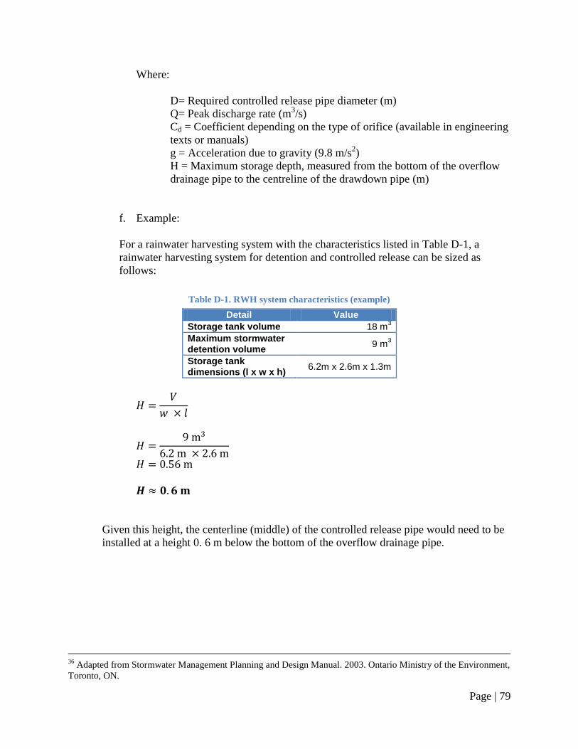
Page | 79
Where:
D= Required controlled release pipe diameter (m)
Q= Peak discharge rate (m3/s)
Cd = Coefficient depending on the type of orifice (available in engineering
texts or manuals)
g = Acceleration due to gravity (9.8 m/s2)
H = Maximum storage depth, measured from the bottom of the overflow
drainage pipe to the centreline of the drawdown pipe (m)
f. Example:
For a rainwater harvesting system with the characteristics listed in Table D-1, a
rainwater harvesting system for detention and controlled release can be sized as
follows:
Table D-1. RWH system characteristics (example)
Detail Value
Storage tank volume 18 m3
Maximum stormwater detention volume
9 m3
Storage tank dimensions (l x w x h)
6.2m x 2.6m x 1.3m
Given this height, the centerline (middle) of the controlled release pipe would need to be
installed at a height 0. 6 m below the bottom of the overflow drainage pipe.
36
Adapted from Stormwater Management Planning and Design Manual. 2003. Ontario Ministry of the Environment,
Toronto, ON.
Page | 80
The peak discharge from the rainwater storage tank, over a 24 hour period would be:
⁄
⁄
Assuming the depth in the cistern is 0.56 m when the full 9 m3 is being stored, the
required pipe size would be:
√
√
√
Thus, from these calculations, a 10 mm diameter pipe is required, however, in practice,
such a small orifice would not be used as it would be prone to clogging, or to freezing
during the winter. A minimum orifice size recommended for controlled release pipes is
75 mm37
. Consult the local conservation authority and/or municipality regarding the
minimum controlled release pipe diameter sizing.
37
Low Impact Development Stormwater Management Manual (Draft).2008. Toronto and Region Conservation
Authority, Toronto, ON. 75 mm is the minimum orifice size required for controlled release pipes in stormwater
retention ponds located in the City of Toronto.
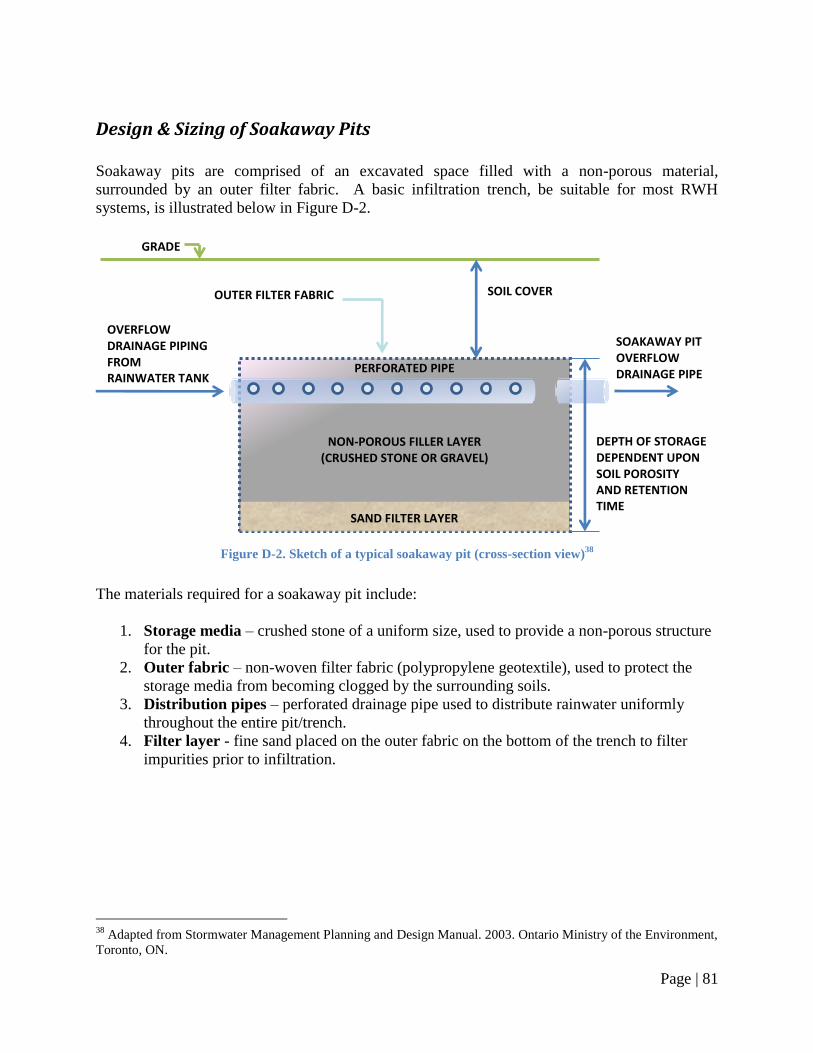
Page | 81
Design & Sizing of Soakaway Pits
Soakaway pits are comprised of an excavated space filled with a non-porous material,
surrounded by an outer filter fabric. A basic infiltration trench, be suitable for most RWH
systems, is illustrated below in Figure D-2.
Figure D-2. Sketch of a typical soakaway pit (cross-section view)
38
The materials required for a soakaway pit include:
1. Storage media – crushed stone of a uniform size, used to provide a non-porous structure
for the pit.
2. Outer fabric – non-woven filter fabric (polypropylene geotextile), used to protect the
storage media from becoming clogged by the surrounding soils.
3. Distribution pipes – perforated drainage pipe used to distribute rainwater uniformly
throughout the entire pit/trench.
4. Filter layer - fine sand placed on the outer fabric on the bottom of the trench to filter
impurities prior to infiltration.
38
Adapted from Stormwater Management Planning and Design Manual. 2003. Ontario Ministry of the Environment,
Toronto, ON.
GRADE
OVERFLOW DRAINAGE PIPING FROM RAINWATER TANK
PERFORATED PIPE
SOIL COVER
DEPTH OF STORAGE DEPENDENT UPON SOIL POROSITY AND RETENTION TIME
SAND FILTER LAYER
NON-POROUS FILLER LAYER (CRUSHED STONE OR GRAVEL)
OUTER FILTER FABRIC
SOAKAWAY PIT OVERFLOW DRAINAGE PIPE
Page | 82
1. General design considerations39
:
a. The soakaway pit should be located at least 4 m [13 ft.] away from a building
foundation or other buried structure, and 1.5 m [5 ft.] from buried water or utility
lines;
b. The length of the pit (parallel to the overflow drainage pipe) should be maximized
compared to the width;
c. The maximum height of the pit/trench should be 1.5 m [5 ft.];
d. The soakaway pit should be buried sufficiently to protect it from freezing.
2. To size a soakaway pit or infiltration trench, the following guidelines are provided for
estimation purposes only40
:
a. The depth of the soakaway pit can be calculated using Equation D-5 (further
details below):
Equation D-5
Where:
d = Maximum allowable depth of the soakaway pit (m)
P = Percolation rate (mm/hour)
T = Drawdown time (hour)
b. Given the storage depth, the size (area) of the soakaway pit can then be calculated
using Equation D-6:
Equation D-6
Where:
A = Surface area of soakaway pit (m2)
V = Runoff volume to be infiltrated (m3)
d = Maximum allowable depth of the soakaway pit (m)
n = Porosity of storage media (0.4 for clear stone)
c. When performing Equation D-5 and Equation D-6, the following sizing
guidelines are recommended:
39
Adapted from Stormwater Management Planning and Design Manual. 2003. Ontario Ministry of the Environment,
Toronto, ON, and Low Impact Development Stormwater Management Manual (Draft).2008. Toronto and Region
Conservation Authority, Toronto, ON. 40
Adapted from Stormwater Management Planning and Design Manual. 2003. Ontario Ministry of the Environment,
Toronto, ON.
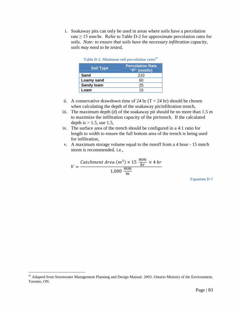
Page | 83
i. Soakaway pits can only be used in areas where soils have a percolation
rate ≥ 15 mm/hr. Refer to Table D-2 for approximate percolation rates for
soils. Note: to ensure that soils have the necessary infiltration capacity,
soils may need to be tested,
Table D-2. Minimum soil percolation rates41
Soil Type Percolation Rate “P” (mm/hr)
Sand 210
Loamy sand 60
Sandy loam 25
Loam 15
ii. A conservative drawdown time of 24 hr (T = 24 hr) should be chosen
when calculating the depth of the soakaway pit/infiltration trench,
iii. The maximum depth (d) of the soakaway pit should be no more than 1.5 m
to maximize the infiltration capacity of the pit/trench. If the calculated
depth is > 1.5, use 1.5,
iv. The surface area of the trench should be configured in a 4:1 ratio for
length to width to ensure the full bottom area of the trench is being used
for infiltration,
v. A maximum storage volume equal to the runoff from a 4 hour - 15 mm/h
storm is recommended. i.e.,
( )
Equation D-7
41
Adapted from Stormwater Management Planning and Design Manual. 2003. Ontario Ministry of the Environment,
Toronto, ON.
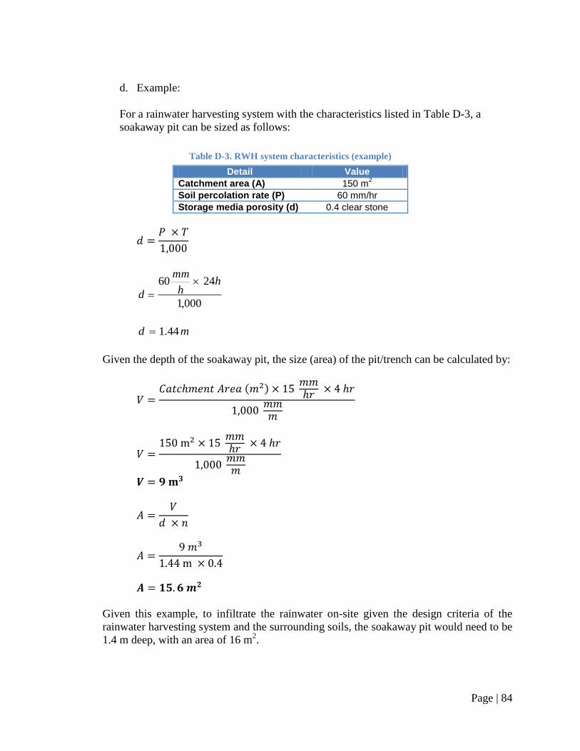
Page | 84
d. Example:
For a rainwater harvesting system with the characteristics listed in Table D-3, a
soakaway pit can be sized as follows:
Table D-3. RWH system characteristics (example)
Detail Value
Catchment area (A) 150 m2
Soil percolation rate (P) 60 mm/hr
Storage media porosity (d) 0.4 clear stone
000,1
2460 hh
mm
d
md 44.1
Given the depth of the soakaway pit, the size (area) of the pit/trench can be calculated by:
( )
Given this example, to infiltrate the rainwater on-site given the design criteria of the
rainwater harvesting system and the surrounding soils, the soakaway pit would need to be
1.4 m deep, with an area of 16 m2.

Page | 85
3. The soakaway pit must be buried at a sufficient depth to protect it from frost. Figure D-3
indicates the required soil cover, based on soil type and depth of soakaway pit.
Figure D-3. Soil cover for soakaway pits, based on frost heave
42
42
Stormwater Management Planning and Design Manual. 2003. Ontario Ministry of the Environment, Toronto, ON.