Embed Size (px)
Citation preview

Section 1 – Training Guide Summary
Section 2 – Wireless InformationSerial Number Supervision
Section 3 – Key Features
Section 4 – Specifications
Section 5 – Compatible Wireless Offerings
Section 6 – PC9155 Suite OverviewCompatible Device/Detector ListPC9155 Enclosure DetailsPC9155 Circuit Board – OverviewPC9155 Circuit Board – TerminalsWT5500 OverviewWT4901 OverviewWT4911 OverviewWT4989 OverviewWS4913 OverviewWS4985 OverviewGS2065 OverviewTL265GS Overview
Section 7 – Programming NavigationGeneral NavigationQuick EnrollTemplate
Section 8 – System Installation
Section 9 – Additional Wireless Programming
Section 10 – I/O Terminal Information
Section 11 – Star Commands
Section 12 – Arming and Disarming
Welcome to the 2-way wireless security suite training guide. This guide is designed to provide technical information about the 2-way wireless security suite in preparation for the upcoming technical presentation (in-class or video conference).
Most of the information outlined in this guide will also be covered during the in-class/video session. The in-class/video session will however primarily focus on key features, installation, product overview etc. It is important to ensure that all of the material in this guide be thoroughly reviewed.
A technical test will be issued at the end of the training session.

Serial Numbers:PC9155:The PC9155 requires that all device/detector are programmed with an 8-digit serial number.
Wireless Devices:1 – Way Devices: the serial number for these devices are 6-digits in length. Since the PC9155 requires that serial number are programmed with 8-digits, enter ‘00’ prior to entering the 6-digit number.
2 – Way Devices: these devices are 8-digits
Wireless SupervisionSupervisory Signal:Each wireless device automatically transmits a supervisory signal every 64 minutes. This signal is automatic and contains the following information:
Contact StateTamper StateBattery Voltage
Supervisory Window:This is a programmable window in the PC9155 control panel (default = 24 hours). It is required that at least one supervisory signal be received by the PC9155 from each device/detector before the end of each supervisory window. If a signal is not received, a Zone Fault trouble condition is generated for the failed device/detector
Wireless Detector Compatibility 1 – Way Detectors:1-way 433MHz detectors are compatible with the PC9155
2 – Way Detectors:2-way 433MHz detectors (contain a prefix ‘WT’) are only compatible with the PC9155 and are NOT compatible with 1-way receivers
List of 1-way receivers:PC5132-433RF5132-433RF5108-433SCW9045/47RFK55XX-433

1-way, 2-way wireless detector support2-way wireless keypad support (WT5500)Wireless Quick EnrollTemplate programmingAccount Code Error CheckingAlternate communications via GSM/GPRS and IPLocal and remote downloading4 communication phone numbers2 Input/Output terminalsFront and back tamperOnboard Siren at 85dBFalse alarm reduction features

Specifications:Number of Zones Supported
34 zones (32 wireless, 2 hardwired)
Number of Key FOBs Supported16
Number of Proximity Tags Supported17
Number of PGMs Supported2
Access Codes17 (16 user codes, 1 system master)
Communication FormatAutomatic SIA, Automatic Contact ID, Pulse, Residential Dial
Number of Keypads4 (WT5500)
Number of Sirens4 (Combination of WT4901/WT4911)
AC Power Requirements16.5VAC, 20VA
Battery Requirements12vdc, 2.3 AH
AUX Current12vdc, 200mA (Max.)
PGM Current50mA (Max.)
Event Buffer500 Events (Time, Date stamped)
Compatible Wireless DevicesAll DSC 433MHz devices (1-way and 2-way)
Compatible Alternate CommunicatorGS2065 – GSM/GPRS Wireless Alarm CommunicatorTL265GS – Internet and GSM/GPRS Dual-path Alarm Communicator


List of devices in the 2-way wireless security suite:- PC9155 control panel- WT5500 2-way wireless keypad*- WT5500P 2-way wireless keypad with prox tag (PT4) support*- WT5500D 2-way wireless keypad (desk stand version)- WT4901 2-way wireless indoor siren*- WT4911 2-way wireless outdoor siren*
List of new 2-way wireless devices:- WT4989 2-way wireless key FOB*
List of new 1-way wireless devices:- WS4913 – 1-way wireless CO detector- WS4985 – 1-way wireless flood sensor
List of current 1-way wireless devices:Motion Detectors:All existing 433MHz wireless detectors are compatibleWS4904P – wireless motion detector with pet-immunity (multiple pets)WLS914 – wireless motion detector with pet-immunity (single pet)
Glassbreak WLS912 – wireless glassbreak detector
Smoke Detectors:WS4916 – wireless smoke detector
Door/Window ContactsEV-DW4917 – wireless recessed door/window contactEV-DW4927 – wireless shock sensorWS4945 – wireless door/window contactEV-DW4955 – wireless door/window contactWS4965 – wireless tri-zone door/window contactEV-DW4975 – wireless door/window contact
Key FOBsWS4939 – wireless 4-button key FOBWS4949 – wireless 2-button key FOB (3 channel)WS4959 – wireless 4-button key FOB (12 channel)WS4969 – wireless 4-button key FOB (built-in LED flashlight)
Panic ButtonWS4938 – wireless single-button panic button
Additional DevicesWS4979 – wireless arm/disarm plate
Note:- only 2-way devices have a prefix of ‘WT’
* 2-way devices are NOT compatible with 1-way receivers
New Alarm Communicators- GS2065 – GSM/GPRS Wireless Alarm Communicator- TL265GS – Internet and GSM/GPRS Dual-path Alarm Communicator
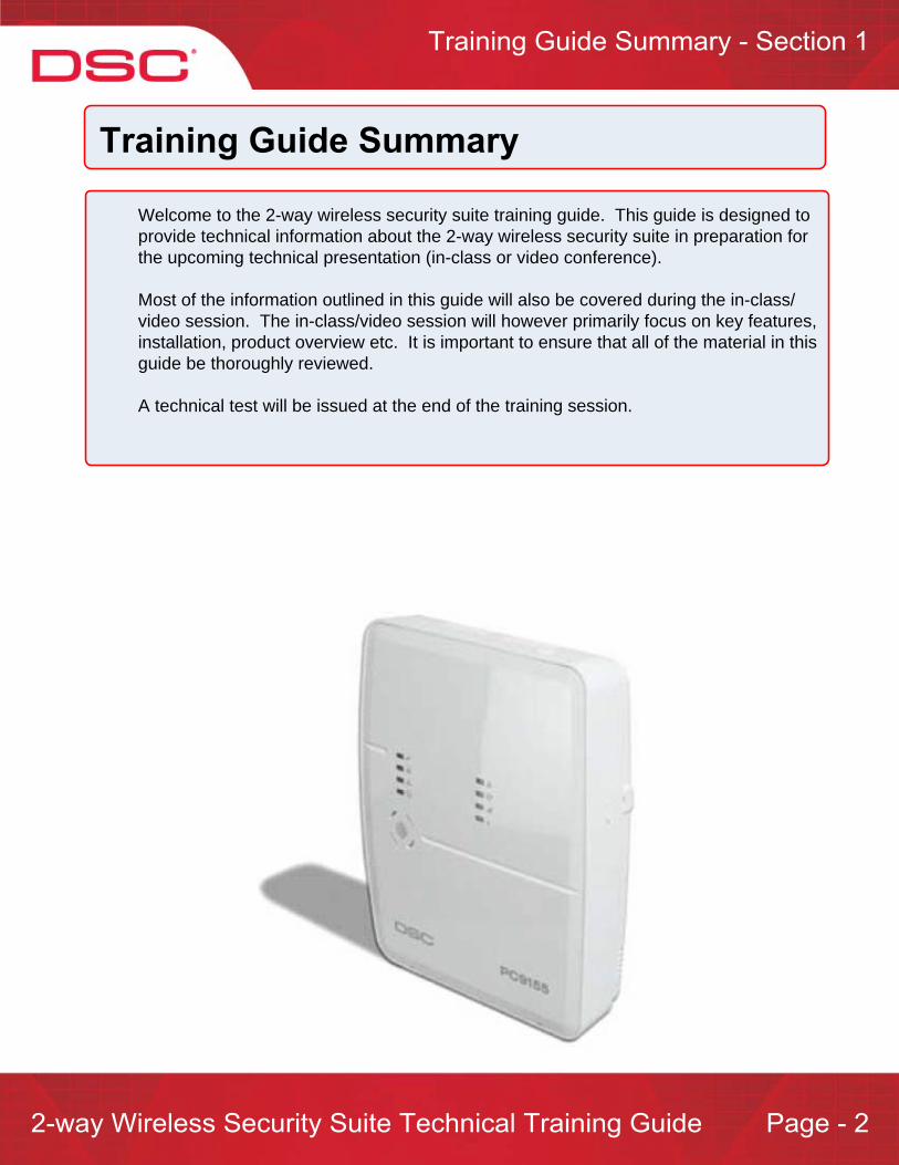
= Siren Grill
= ‘Ready’. This indicator is active when all zones are secure
= ‘Armed’. This indicator is active when the system is armed
= ‘Trouble’. This indicator is active when a system trouble is present
= ‘AC Status’. This indicator is active when AC power is present
= ‘Communicator Trouble’. This indicator is active when a trouble is present on the GS/IP module = ‘Network ’. This indicator is active when the internet communicator is absent
= ‘Signal Strength (Hi)’. This indicator is active when the GS signal strength is good
= ‘Signal Strength (Lo)’. This indicator is active when the GS signal strength is poor
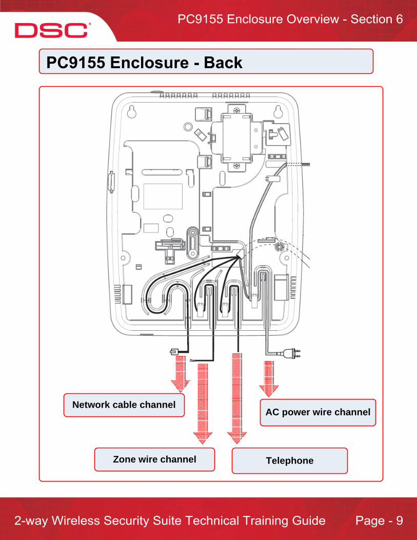
AC power wire channel
Zone wire channel
Network cable channel
Telephone
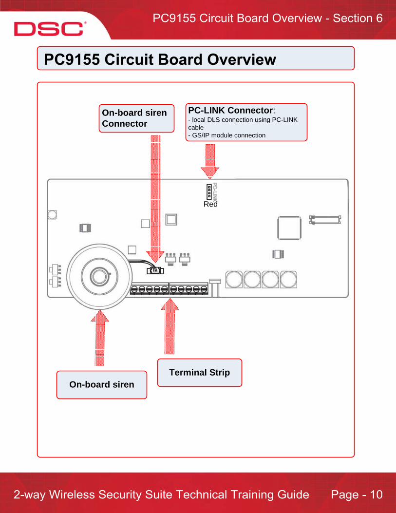
Red
PC-LINK Connector:- local DLS connection using PC-LINK cable- GS/IP module connection
On-board siren
On-board siren Connector
Terminal Strip
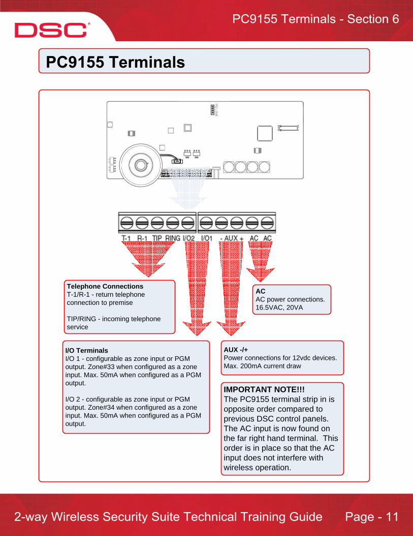
Telephone ConnectionsT-1/R-1 - return telephone connection to premise
TIP/RING - incoming telephone service
I/O TerminalsI/O 1 - configurable as zone input or PGM output. Zone#33 when configured as a zone input. Max. 50mA when configured as a PGM output.
I/O 2 - configurable as zone input or PGM output. Zone#34 when configured as a zone input. Max. 50mA when configured as a PGM output.
AUX -/+Power connections for 12vdc devices. Max. 200mA current draw
ACAC power connections. 16.5VAC, 20VA
IMPORTANT NOTE!!!The PC9155 terminal strip in is opposite order compared to previous DSC control panels. The AC input is now found on the far right hand terminal. This order is in place so that the AC input does not interfere with wireless operation.
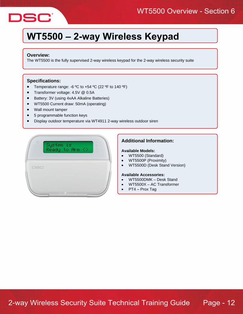
Overview:The WT5500 is the fully supervised 2-way wireless keypad for the 2-way wireless security suite
Specifications:Temperature range: -6 ºC to +54 ºC (22 ºF to 140 ºF)Transformer voltage: 4.5V @ 0.5ABattery: 3V (using 4xAA Alkaline Batteries) WT5500 Current draw: 50mA (operating)Wall mount tamper5 programmable function keysDisplay outdoor temperature via WT4911 2-way wireless outdoor siren
Additional Information:
Available Models:WT5500 (Standard)WT5500P (Proximity)WT5500D (Desk Stand Version)
Available Accessories:WT5500DMK – Desk StandWT5500X – AC TransformerPT4 – Prox Tag

Status LED Indicators1 – Ready 2 – Armed3 – Trouble 4 – AC Status
Function Keys5 – Stay Arm6 – Away Arm7 – Chime Enable/Disable8 – Zone Bypass9 – Quick Exit
Emergency Keys10 – Panic11 – Auxiliary 12 - Fire
13 – Arrow Keys14 – Prox Sensor (WT5500P Only)15 – Light Sensor16 – Custom LCD Screen
10 9
8
7
6
5
4
3
2
1
11
12
13
14
15
16

Overview:The WT4901 is a fully supervised 2-way wireless indoor siren for the 2-way wireless security suite
Specifications:Operating Temperature: -10 ºC to +55 ºC (14 ºF to 131 ºF)Batteries: (4) AA 1.5V Alkaline Battery Life: 2 years (typical usage)Low Battery Level: 5.6 V, pre-determinedAlarm Signals – Output Level: 85dB @ 3m(high volume)Other Signals – Output Level: 65db @ 3m(medium volume)
Operation
Siren Output Pattern:Steady (Burg)Pulsed (Fire)Temporal Three (Fire)CO Output Pattern
Additional Signal Outputs:Placement Test ResultBuzzer Notification*Door Chime* System TestSystem Troubles*
*Programmable feature
Features:Siren sounds for: Alarms, Door Chime, Entry and Exit Delay, Trouble IndicationsTransmits module status including tamper, low battery and RF faultCase and wall tamperFully supervised

Test Button:Press and hold the test button for 5 seconds to confirm operation. The sounder will activate for 4 seconds. 2 seconds at medium volume and 2 seconds at full volume.
Siren
Battery Compartment:4xAA 1.5V Alkaline
Batteries
Tamper
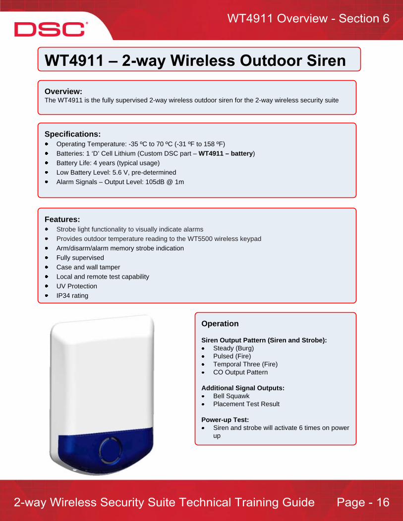
Overview:The WT4911 is the fully supervised 2-way wireless outdoor siren for the 2-way wireless security suite
Specifications:Operating Temperature: -35 ºC to 70 ºC (-31 ºF to 158 ºF)Batteries: 1 ‘D’ Cell Lithium (Custom DSC part – WT4911 – battery)Battery Life: 4 years (typical usage)Low Battery Level: 5.6 V, pre-determinedAlarm Signals – Output Level: 105dB @ 1m
Operation
Siren Output Pattern (Siren and Strobe):Steady (Burg)Pulsed (Fire)Temporal Three (Fire)CO Output Pattern
Additional Signal Outputs:Bell SquawkPlacement Test Result
Power-up Test:Siren and strobe will activate 6 times on power up
Features:Strobe light functionality to visually indicate alarmsProvides outdoor temperature reading to the WT5500 wireless keypadArm/disarm/alarm memory strobe indicationFully supervisedCase and wall tamperLocal and remote test capabilityUV ProtectionIP34 rating

Battery Pack
Battery Connector
Battery Cable
Tamper
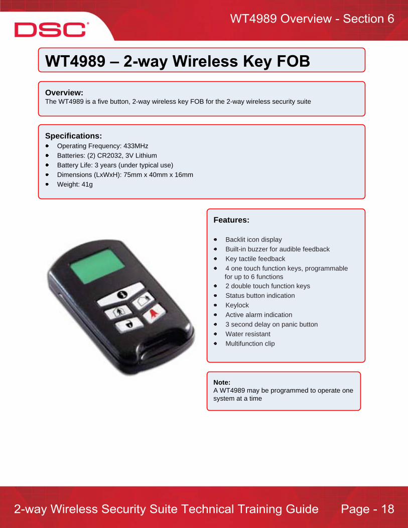
Overview:The WT4989 is a five button, 2-way wireless key FOB for the 2-way wireless security suite
Specifications:Operating Frequency: 433MHzBatteries: (2) CR2032, 3V Lithium Battery Life: 3 years (under typical use)Dimensions (LxWxH): 75mm x 40mm x 16mmWeight: 41g
Features:
Backlit icon display Built-in buzzer for audible feedback Key tactile feedback 4 one touch function keys, programmable
for up to 6 functions2 double touch function keys Status button indication Keylock Active alarm indication 3 second delay on panic button Water resistant Multifunction clip
Note:A WT4989 may be programmed to operate one system at a time

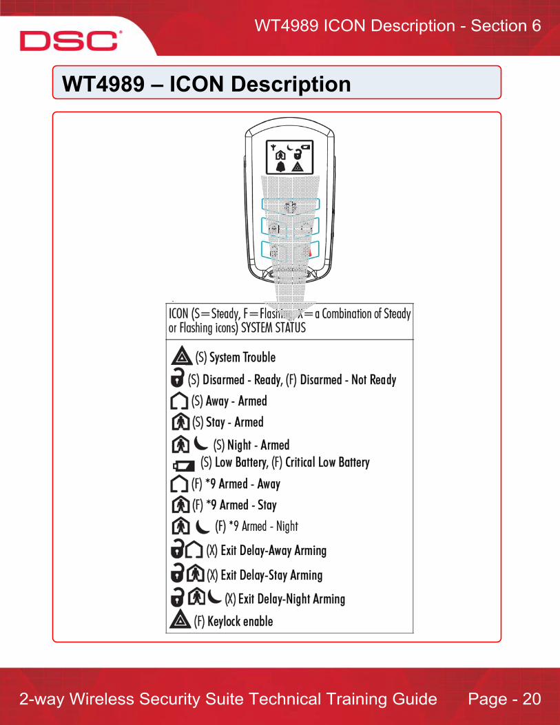
Status – press for 1 second to display system status via LCD ICON display
Button#1Stay Arm
Button#2Away Arm
Button#3Disarm
Button#4Panic
Button#5Command Output#1
Button#6Command Output#2
Button#1Stay Arm
Button#2Away Arm
Button#3Disarm
Button#4Panic
Status Request/Keylock
KeylockEnable/Disable Status Button#2
Away Arm

Programming:The WT4989 supports internal programming that provides the user to configure the remote to suit their needs.
To customize the WT4989:Step 1 – Press and hold all four buttons simultaneously for 5 seconds. The
ICON will flash to indicate that programming has been enteredStep 2 – Press the button 1-4 as per the desired feature listing in the chart below
Note: - programming will last for 5 seconds

Overview:The WS4913 1-way wireless CO detector supports the ability to detect excess carbon monoxide levels
Specifications:Sensor: Electrochemical carbon monoxide sensor Dimensions: 1.42" x 4.72" (36 mm x 120 mm)Battery Life: 5 years
Operating Temperature: 0 ºC to 38 ºC
Battery: Duracell CR123A
Supported Receivers: PC9155 Only
Features:Low sensitivity supervisionOnboard LEDs indicate:
Red – AlarmYellow – TroubleGreen – Power
Hush featureWall tamper
Important Note:- the WS4913 is NOT compatible with 1-way receivers

Operation:The CO alarm will go into alarm when the concentration of carbon monoxide (CO) in the air around the device exceeds the 'alarm' thresholdDuring an alarm, the red LED light will flash quickly and the buzzer will activate (repeating 4 quick beeps, pause 5 seconds)After 4 minutes of being in alarm the pause between beeps will change to 60 seconds (4 quick beeps, pause 60 seconds)The alarm will continue to sound until the concentration of CO in the air around detector drops below the ‘alarm’ threshold or the reset button is pressed
Alarm Indicators:Power ON mode: when the batteries are installed, the LED will blink 3 times and the built in sounder will activate for half a second
Stand-by mode: the green LED will flash once every 60 seconds to indicate normal operation
Low battery warning mode: in the event of a low battery condition, the yellow LED will blink and the built in sounder will activate once every 60 seconds
Tamper mode: if the case tamper is activated, the built in sounder will activate once every 60 seconds and the yellow LED will be on continuous until the unit is mounted on its backplate.
Trouble mode: if the yellow LED quickly flashes 2, 3 or 4 times every 60 seconds an internal trouble has occurred and the WS4913 will need to be replaced:
2 Times – Malfunction error: indicates an internal fault3 Times – Low sensitivity mode: indicates an internal fault4 Times – End of life signal mode: indicates that the detector is reaching the end of useful life (approximately 5 years from initial installation)

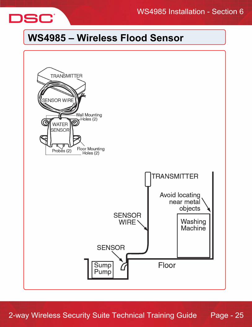
Overview:The WS4985 1-way wireless flood sensor supports the ability to detect excess water levels
Specifications:Operating Frequency: 433MHzBatteries: (2) CR2032, 3V LithiumBattery Life: 3 yearsDimensions: 75mm x 40mm x 16mmWeight: 41g

Overview:The GS2065 provides primary or backup GSM/GPRS communication for the 2-way wireless security suite
Specifications:Dimensions : 3.937"x5.875"x0.625" (100mmx150mmx15mm)Weight : 68 gInput Voltage : 10 to 13.8 V (from the PC-Link header)Current Draw : 100 mA at 12V (400 mA during the GSM transmission)Operating Environment : 5 º C to 40º C (40º F to 104º F)
Features:Back up and primary GSM/GPRS alarm communicationPanel remote uploading/downloading support via GSM/GPRSSupervision heartbeats via GSM/GPRS128-bit AES encryption over GSM/GPRSFull event reportingSIA formatPC-Link connectionSIM card includedSignal strength and trouble displayActivating and initializing through Connect 24Quad-Band: 850 MHz, 1900 MHz, 900 MHz and 1800 MHz
Compatible Receivers:Sur-Gard System I Receiver: version 1.10 and higherSur-Gard System II Receiver: version 2.00 and higherSur-Gard SG-DRL3-IP: version 2.20 and higher (for Sur-Gard System III Receiver)

Overview:The TL265GS is an Internet and GSM/GPRS Dual-Path alarm communicator for the 2-way wireless security suite
Specifications:Dimensions : 3.937"x5.875"x0.75" (100mmx150mmx18mm)Weight : 78 gInput Voltage : 10 to 13.8 V (from the PC-Link header)Current Draw : 100 mA at 12V (400 mA during the GSM transmission)Operating Environment : 5 º C to 40º C (40º F to 104º F)
Features:Fully redundant Internet and GSM/GPRS dual-path alarm communicationIntegrated call routing Panel remote uploading/downloading support via GSM/GPRS and InternetSupervision heartbeats via GSM/GPRS and Internet 128-bit AES encryption via GSM/GPRS and Internet Full event reporting SIA format PC-Link connection SIM card included Signal strength and trouble display Activating and initializing through Connect 24Quad-Band: 850 MHz, 1900 MHz, 900 MHz and 1800 MHz
Compatible Receivers:Sur-Gard System I Receiver: version 1.10 and higherSur-Gard System II Receiver: version 2.00 and higherSur-Gard SG-DRL3-IP: version 2.20 and higher (for Sur-Gard System III Receiver)

Programming NavigationNavigating through programming is simple and intuitive. To enter Installer programming:
Step 1 – Enter [*][8] + [Installer Code]The default installer code is [5555]
Step 2 – Enter the required 3-digit installer programming section (‘Enter Section’ will be displayed)
At this point, you have the option of choosing the desired programming method:
Section Number ProgrammingQuick EnrollTemplate programming
Section Number Programming:This is the traditional method of programming and allows the user to enter any programming section.
When using this method, there are two types of programming sections:Toggle SectionsData Sections
Toggle Section:Toggle sections consist of a series of options that may be enabled or disabled. To toggle an option ON or OFF, press the key number corresponding to the option.
Option Enabled Option Disabled
To exit a toggle section, press [#]
Data Section:Data sections require multiple 2 or 3 digit number entries. Data sections allow for both decimal or hexadecimal entries (some data sections have fixed values where the available entries are provided from a chart. For example ‘Zone Definitions’). To enter hexadecimal data, first enter [*] followed by [1] to [6] to enter [A] to [F] respectively. To exit hexadecimal programming, enter [*] again.
To exit a data section, either complete all entries or press [#]
Once you exit a programming section, a new 3-digit section may be entered

Quick Enroll:The Quick Enroll programming method is designed to reduce the time required to program wireless devices/detectors.
The following information is programmable when using the Quick Enroll method:
Serial Number - no need for programming serial numbers manually. Therefore preventing programming errors Zone Number (detectors)Zone Definitions (detectors)Slot Number (Keypads, Sirens, FOBs)
Note:- pressing [#] will return to the previous step
Enter Installer Programming
Detector
Enter Section [898]
Trigger the detector
Correct Serial Number?
Enter [*] to confirm
Enter Zone Number
Enter Zone Definition
YES
NOEnter [#]
Enter Installer Programming
Keypad/Siren
Enter Section [898]
Trigger the keypad ([*] and [1]) or siren (insert batteries or
press tamper)
Correct Serial Number?
Enter [*] to confirm
Enter slot number1-4
YES
Enter Installer Programming
Key FOB
Enter Section [898]
Press button on FOB
Correct Serial Number?
Enter [*] to confirm
Enter slot number01-16
YES
NOEnter [#]
NOEnter [#]

Template Programming:Template programming provides a quick and easy method of programming the control panel’s core features. To use template programming, perform the following:
Step 1 – Enter Installer programming, [*][8] + [Installer Code]Step 2 – Enter Section [899]Step 3 – The keypad will display 4-digits. Each digit in each segment represents the template
programming currently selected.1st Digit – Zone Definitions2nd Digit – Communications Programming (Format)3rd Digit – Reporting Code and Call Direction Configurations4th Digit – DLS Configuration
Step 4 – Move the cursor to each digit segment and enter the desired configuration numberStep 5 – Enter [#]Step 6 – Enter the following data:
Central station telephone number
Panel account code
DLS access code
Entry & Exit time
Installer code
Note: If ‘0’ is entered for the 1st digit, the system will keep the zone definitions selected when the ‘Quick Enrollment’ was performed. Selecting any other digit will change the previously programmedinformation.
Example: A system requires the following configuration:
Required Programming in Section [899] = 4211
No DLS RequiredDLS Options
Alarms and Maintenance Reporting (Telephone#1)Reporting Codes
Automatic SIACommunication Options
Zone#1, #2 = Delay 1Zone#3 - #8 = Instant
Zone Definitions
No DLS RequiredDLS Options
Alarms and Maintenance Reporting (Telephone#1)Reporting Codes
Automatic SIACommunication Options
Zone#1, #2 = Delay 1Zone#3 - #8 = Instant
Zone Definitions

BEFORE YOU BEGIN
Have the following ready before initializing the system:AC transformerWire attached to transformerControl panel backup batteryBattery connection harnessBatteries for WT5500 2-way wireless keypadScrewdriver
Step 1 – Mounting the PC9155
It’s important to ensure that the PC9155 is mounted in a location that will allow for proper transmission of wireless information. Use the following guidelines when finding a location:
Central locationDryWithin operating temperature rangeAway from sources of interference
Summary of Installation Steps
Step 1 – Mounting the PC9155
Step 2 – Apply power to the PC9155
Step 3 – Enroll the first WT5500 wireless keypad
Step 4 – Enroll additional wireless devices and detectors
Step 5 – Test all wireless devices and detectors
Step 6 – Additional installer programming

Step 2 – Apply power to the PC9155
Connect AC power and battery. During the first 2 minutes of power the ‘Ready’ and ‘AC’ indicators will flash
Step 3 – Enroll the first WT5500 wireless keypad
Press and hold the [*] and [1] simultaneously within the first 2 minute of applying power to the PC9155 control panel. When successfully enrolled, the keypad will display ‘WFKP Enrollment Successful’
Note: this must be performed within the first 2 minutes of applying power to the PC9155. If the 2 minute expires prior to this operation, remove power (AC and battery) from the PC9155 and reconnect.
The PC9155 is now ready for additional keypad, device and detector enrollment
Step 4 – Enroll additional wireless devices and detectors
The next series of pages in this section includes instructions on enrolling the following items using the Quick Enroll method:
Additional WT5500 keypadsWT4901 and WT4911 sirensWireless detectorsWireless key FOBsProx Tags
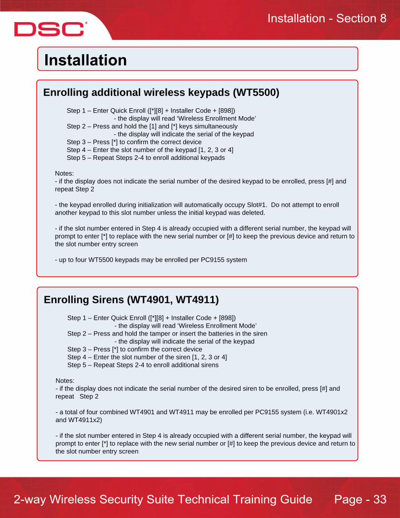
Enrolling additional wireless keypads (WT5500)Step 1 – Enter Quick Enroll ([*][8] + Installer Code + [898])
- the display will read ‘Wireless Enrollment Mode’Step 2 – Press and hold the [1] and [*] keys simultaneously
- the display will indicate the serial of the keypad Step 3 – Press [*] to confirm the correct deviceStep 4 – Enter the slot number of the keypad [1, 2, 3 or 4]Step 5 – Repeat Steps 2-4 to enroll additional keypads
Notes: - if the display does not indicate the serial number of the desired keypad to be enrolled, press [#] and repeat Step 2
- the keypad enrolled during initialization will automatically occupy Slot#1. Do not attempt to enroll another keypad to this slot number unless the initial keypad was deleted.
- if the slot number entered in Step 4 is already occupied with a different serial number, the keypad will prompt to enter [*] to replace with the new serial number or [#] to keep the previous device and return to the slot number entry screen
- up to four WT5500 keypads may be enrolled per PC9155 system
Enrolling Sirens (WT4901, WT4911)Step 1 – Enter Quick Enroll ([*][8] + Installer Code + [898])
- the display will read ‘Wireless Enrollment Mode’Step 2 – Press and hold the tamper or insert the batteries in the siren
- the display will indicate the serial of the keypad Step 3 – Press [*] to confirm the correct deviceStep 4 – Enter the slot number of the siren [1, 2, 3 or 4]Step 5 – Repeat Steps 2-4 to enroll additional sirens
Notes: - if the display does not indicate the serial number of the desired siren to be enrolled, press [#] and repeat Step 2
- a total of four combined WT4901 and WT4911 may be enrolled per PC9155 system (i.e. WT4901x2 and WT4911x2)
- if the slot number entered in Step 4 is already occupied with a different serial number, the keypad will prompt to enter [*] to replace with the new serial number or [#] to keep the previous device and return to the slot number entry screen
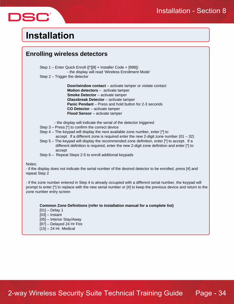
Enrolling wireless detectors
Step 1 – Enter Quick Enroll ([*][8] + Installer Code + [898])- the display will read ‘Wireless Enrollment Mode’
Step 2 – Trigger the detector
Door/window contact – activate tamper or violate contactMotion detectors – activate tamperSmoke Detector – activate tamperGlassbreak Detector – activate tamperPanic Pendant – Press and hold button for 2-3 secondsCO Detector – activate tamperFlood Sensor – activate tamper
- the display will indicate the serial of the detector triggered Step 3 – Press [*] to confirm the correct deviceStep 4 – The keypad will display the next available zone number, enter [*] to
accept. If a different zone is required enter the new 2-digit zone number (01 – 32)Step 5 – The keypad will display the recommended zone definition, enter [*] to accept. If a
different definition is required, enter the new 2-digit zone definition and enter [*] to accept
Step 6 – Repeat Steps 2-5 to enroll additional keypads
Notes: - if the display does not indicate the serial number of the desired detector to be enrolled, press [#] and repeat Step 2
- if the zone number entered in Step 4 is already occupied with a different serial number, the keypad will prompt to enter [*] to replace with the new serial number or [#] to keep the previous device and return to the zone number entry screen
Common Zone Definitions (refer to installation manual for a complete list)[01] – Delay 1 [03] – Instant [05] – Interior Stay/Away[87] – Delayed 24 Hr Fire[15] – 24 Hr. Medical

Enrolling wireless key FOBs (1-way and 2-way)Step 1 – Enter Quick Enroll ([*][8] + Installer Code + [898])
- the display will read ‘Wireless Enrollment Mode’Step 2 – Press a button on the FOB to be enrolled
- the display will indicate the FOB Step 3 – Press [*] to confirm the correct deviceStep 4 – Enter the 2-digit slot number of the FOB ([01] – [16])
Notes: - if the display does not indicate the serial number of the desired detector to be enrolled, press [#] and repeat Step 2
- if the slot number entered in Step 4 is already occupied with a different serial number, the keypad will prompt to enter [*] to replace with the new serial number or [#] to keep the previous device and return to the slot number entry screen
- the default programming for the key FOBs are as follows:Button 1 = StayButton 2 = AwayButton 3 = DisarmButton 4 = PanicButton 5 = Command Output#1*Button 6 = Command Output#2*
*WT4989 OnlyTo change, enter Sections [804], Sub-Section [141 – 156]
Enrolling Prox Tags (WT5500P Only)Step 1 – Enter Access Code Programming ([*][5] + [Master or Supervisory Code])Step 2 – Select a user code number (01 -16, 40)to be associated with the prox tagStep 3 – If no code is programmed for the user, enter a 4 or 6-digit number. If a 4 or 6-digit number
already exist, scroll through the code numberStep 4 – The keypad will prompt to present the prox tag. The message ‘Tag Accepted’ will be
display if correctly enrolled

Step 5 – Test all wireless devices and detectors
Step 1 – Enter Wireless Placement Test ([*][8] + Installer Code + [904])- the display will read ‘Activate Device For Test’
Step 2 – Activate each wireless device/detector one at a time from the proposed mounting location
Wireless Keypad – [*] and [1] simultaneouslyWireless sirens (WT4901, WT4911) – activate tamperDoor/window contact – activate tamper or violate contactMotion detectors – activate tamperSmoke Detector – activate tamperGlassbreak Detector – activate tamperPanic Pendant – Press and hold button for 2-3 secondsCO Detector – activate tamperFlood Sensor – activate tamper
Step 3 – The test result will be indicated:
Good Result Bad ResultKeypad Display ‘Location is Good’ ‘Location is Bad’Siren* 1 Squawk 3 Squawks
* PC9155 and WT4901
Note:- the above placement test is when enabled for the ‘Global Placement Test’. If ‘’Individual Placement Test’, a different section number exits for each type of device:
Step 6 – Additional installer programming
After the PC9155 has been initialized and the wireless devices/detectors have been enrolled and tested, the next step is to program additional system information. Additional programming may be performed using Template Programming covered in Section XX
This includes the following:
Zone Definitions:
System Times
Installer Code
Telephone Number
Communication Format
DLS Options
The following are common template programming entries:
Automatic SIA, DLS Enabled =X212
Automatic SIA, No DLS = X211
Contact ID, DLS Enabled = X612
Contact ID, No DLS = X611
Where ‘X’ = Zone Definition configuration entry.

ReplaceThere are two methods for replacing wireless devices:
Method#1 – Quick Enroll
Step 1 – Enter Quick Enroll ([*][8] + Installer Code + [898])Step 2 – Trigger the device or detector
Wireless Keypad – [*] and [1] simultaneouslyWireless sirens (WT4901, WT4911) – activate tamperDoor/window contact – activate tamper or violate contactMotion detectors – activate tamperSmoke Detector – activate tamperGlassbreak Detector – activate tamperPanic Pendant – Press and hold button for 2-3 secondsCO Detector – activate tamperFlood Sensor – activate tamper
Step 3 – Enter the slot number of the device or the zone number of the device/detector to be replacedStep 4 – Enter [*] to confirm
Method#2 – Manual Programming
Step 1 – Enter Installer Programming ([*][8] + Installer Code)Step 2 – Enter Section [804]Step 3 – Enter the 3-digit zone numberStep 4 – The keypad will display the current serial number. Enter the new 8-digit serial number
Delete
Step 1 – Enter Installer Programming ([*][8] + Installer Code)Step 2 – Enter Section [804]Step 3 – Enter the 3-digit serial number location*Step 4 – The keypad will display the current serial number, replace the serial number with 0's
* Zone = Sections [001] – [132] FOB = Sections [101] – [116] Keypad = Sections [201] – [204] Siren = Sections [301] – [304]
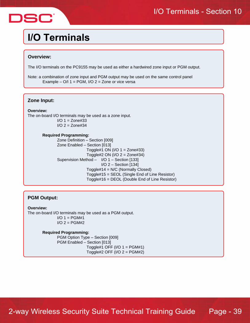
Overview:
The I/O terminals on the PC9155 may be used as either a hardwired zone input or PGM output.
Note: a combination of zone input and PGM output may be used on the same control panel Example – O/I 1 = PGM, I/O 2 = Zone or vice versa
Zone Input:
Overview:The on-board I/O terminals may be used as a zone input.
I/O 1 = Zone#33I/O 2 = Zone#34
Required Programming:Zone Definition – Section [009]Zone Enabled – Section [013]
Toggle#1 ON (I/O 1 = Zone#33)Toggle#2 ON (I/O 2 = Zone#34)
Supervision Method – I/O 1 – Section [133] I/O 2 – Section [134]
Toggle#14 = N/C (Normally Closed)Toggle#15 = SEOL (Single End of Line Resistor)Toggle#16 = DEOL (Double End of Line Resistor)
PGM Output:
Overview:The on-board I/O terminals may be used as a PGM output.
I/O 1 = PGM#1I/O 2 = PGM#2
Required Programming:PGM Option Type – Section [009]PGM Enabled – Section [013]
Toggle#1 OFF (I/O 1 = PGM#1)Toggle#2 OFF (I/O 2 = PGM#2)

[*][1] – Zone Bypass:Summary: Zone bypassing allows for a zone or series of zones to be ignored during the next arming. This command is performed when the system is disarmed.
Operation:Bypass a single zoneStep 1 – [*][1]Step 2 –Enter 2-digit zone numberStep 3 –Press [#]
Bypass multiple zonesStep 1 –[*][1]Step 2 –Enter 2-digit zone number of first zone to bypassStep 3 –Repeat step#2 for additional zones to be bypassedStep 4 –Press [#]
Unbypass a zoneMethod#1Step 1 –[*][1]Step 2 –Enter 2-digit zone number of previously bypassed zone or zonesStep 3 –Press [#]
Method#2Bypassed zone will automatically unbypass when the system is disarmed
[*][1] – Reactivate Stay/Away Zones:Summary: This command incorporated previously bypassed zones into the system. This command may be performed when the system is armed in the ‘Stay’ mode.
Operation:[*][1] while armed in the ‘Stay’ mode
Note: when performed, the system will initiate ‘Exit Delay’ (silent). This will allow for the users to leave the area of the reactivated zone or zones avoiding false alarms.

[*][2] – System Troubles:Summary: This command is used to display system troubles.
Operation:[*][2]
[*][2] – TroublesOverview: This command is used to display system troubles.[1] - Service Required [1] – Low Battery [2] – General System Trouble [3] – General System Tamper[2] - AC Trouble[3] - TLM Trouble (Telephone Line Monitor)[4] - FTC Trouble (Failure To Communicate)[5] - Zone Fault Trouble Including Fire Zones[6] - Zone Tamper Trouble[7] - Wireless Device Low Battery Trouble[8] - Loss of Time/Date Trouble
[1] - Service Required This trouble is generic and requires that the [1] button be entered for specific details. Once selected, the following trouble conditions may appear:[1] - Low BatteryThis trouble indicates that the voltage level on the control panel's backup battery is low or not connected.The trouble is generated when the battery voltage is below 7.2vdc and restored when the voltage reaches 7.6vdc or higher.[2] - General System TroubleA General System Trouble may occur on the system if the system has detected the presence of an RF jam condition.[3] - General System TamperThis trouble condition is generated when the cover tamper is tripped.
[2] - AC TroubleThis trouble condition is generated when AC power is removed from the control panel
[3] - TLM Trouble (Telephone Line Monitor)This trouble condition is generated when the control panel loses the telephone line connection between RING/TIP (less than 3vdc)
[*][2] – System Troubles (continued):
[4] - FTC Trouble (Failure To Communicate)This trouble condition is generated when the control panel fails to report a signal to the central station
[5] – Wireless Device/Detector Fault or DEOL Zone FaultA zone fault condition is generated due to any of the following:Wireless - If a wireless device fails to report a status or supervisory signal within the wireless supervisory window (Zone, Keypad or Siren)DEOL (Double End Of Line) - If a short circuit is detected.
[6] - Wireless Device/Detector Tamper or DEOL Zone TamperA zone tamper condition is generated due to any of the following:Wireless - If the tamper on a wireless device is violated (Zone, Keypad or Siren)DEOL (Double End Of Line) - If a open circuit is detected
[7] - Wireless Device Low Battery TroubleThis trouble is generated when a low battery condition is detected on a wireless device
[8] - Loss of Time/Date TroubleThis trouble condition is generated when the internal clock (time/date) needs to be reset due to a loss of power (AC/DC)
Note: pressing [*] with this trouble is displayed will automatically take the user to time/date programming
For GS2065 and TL265GS trouble conditions, please refer to the respective installation manuals

[*][3] – Alarm Memory:Summary: This command is used to display zones which were in alarm during the last armed state.
Operation:[*][3]
Notes:- alarm memory will be cleared when the system is rearmed. - If the alarm memory has been cleared, the event buffer can be used to display previous alarms- alarm memory is clear the next time the control panel is armed
[*][4] – Enable/Disable Door Chime:Summary: This command is used to enable/disable the door chime feature.
Operation:[*][4]
Enabled = 3 beeps, ‘CHIME ON’ is displayed for 2 secondsDisabled = 1 tone, ‘CHIME OFF’ is displayed for 2 seconds
[*][5] – Access Code Programming:Summary: This command is used to modify user access codes.
Access Code Breakdown[01] - [16] - User Codes (default = 'AAAA'), [40] - Master Code (default = '1234')
Operation:Adding/Editing User CodeStep 1 - Enter [*][5][Master Code]Step 2 - Enter user code numberStep 3 - Enter new 4 or 6-digit code
Note: - if using a WT5500P, the user will be prompted to present a prox tag to associate to the user code after Step 3. If no prox tag is to be assigned to user, enter [#]
Deleting User CodeStep 1 - Enter [*][5][Master Code]Step 2 - Enter user code numberStep 3 - Enter [*]
Note:- if a prox tag was assigned to the user, both the 4 or 6-digit user code and prox tag will be deleted
Access Code Attributes - Code OptionsOperation:Step 1 - Enter [*][5][Master Code]Step 2 - Enter [9]Step 3 - Enter user code numberStep 4 - Enable/disable desired option
Option [1] – Supervisor’s CodeThis option provides the user code with the ability to enter the [*][5] User Code Programming and [*][6] User Functions.
Option [2] - DuressThis option enabled the user code as a duress code. When entered, the control panel will report a ‘Duress Code’ to the central station (if programmed)
Option [3] – BypassThis option is only applicable when the toggle option 'Bypass Requires Code' is enabled (Section [015], Option [5] ON). If enabled, this access code may be used to enter the bypass mode. If this option is enabled (Bypass Requires Code), the user must enter a code with the 'Bypass' attribute enabled after entering [*][1] before the keypad will enter the bypass mode.
Option [7] - Bell Squawk On Access Code EntryIf enabled, a bell squawk will only be performed when an access code is used to arm/disarm.
Option [8] - One-Time User CodeIf enabled and this user code performs a disarming, the system will delete the 4-digit user code the next time the control panel is armed. Any of the 16 user codes can be programmed to be one-time use codes. The code number will be restored at midnight.
[*][6] – User Functions:[*][6] + [Master Code or Supervisory Code] + [Option]
Option [1] – Program Time/Date Step 1 – [*][6]+ [Master Code or Supervisory Code]Step 2 – Press [1] Step 3 – [HH:MM MM:DD:YY]
The control panel Time/Date needs to be programmed each time AC and backup battery are removed.
Additional Information – when AC and backup battery are removed, the control panel will log a ‘Cold Start’ to the event buffered when power is restored
Option [4] – System Test Step 1 – [*][6]+ [Master Code or Supervisory Code]Step 2 – Press [4]
When initiated, the control panel will test the following:- Keypad (LED indicators, LCD screen, buzzer)- Bell output (PC9155 siren and WT4901/WT4911)- Battery - Central station communications (reports a ‘System Test’ reporting code)
Option [5] – User Enabled DLS Window Step 1 – [*][6]+ [Master Code or Supervisory Code]Step 2 – Press [5]
When initiated, the control panel will answer an incoming DLS call (Double Call) for the next 6 hours*
* may be programmed to answer for 1 hour when initiated, Section [702], Toggle#7
Option [6] – User Initiated Call-upStep 1 – [*][6]+ [Master Code or Supervisory Code]Step 2 – Press [6]
When initiated, the control panel will call the DLS computer
Option [8] – User Walk Test ModeStep 1 – [*][6]+ [Master Code or Supervisory Code]Step 2 – Press [8]

[*][6] – User Functions (Continued):
Option [8] – Late to Open Enable/Disable When enabled, the control panel will report a ‘Late To Open’ reporting code to the central station if the system is not disarmed before the time programmed in Option [9] is reached
Option [9] – Late to Open Time of DayThis option is used to specify the ‘Late to Open’ time
Step 1 – [*][6]+ [Master Code or Supervisory Code]Step 2 – Press [9] Step 3 – Press [1 -7] for the required day of the week (1 = Sunday)Step 4 – Enter HH:MM (24 – hour format)
LCD Options:Additional LCD options are available when access the ‘User Functions’. These options are as following:
Event BufferContrast *Brightness *Buzzer Volume*
* To adjust the options, use the keypad scroll buttons. When the desired option appears on the display press the [*] button to select. Use the scroll buttons to select the desired level. Press [#] to exit
Event Buffer:Overview:The event buffer stores the last 500 events generated on the system. These events include:
Alarms/RestoresTroublesTests[*] Commands
Viewing Events:Step 1 – [*][6]+ [Master Code or Supervisory Code]Step 2 – Press [*] when ‘View Event Buffer’ is displayedStep 3 – The display will show the most recent event (Event 001)
Each event is display in 2 separate levels:Level 1 – displays the number of the event (The most recent event is 000), followed by the partition label
Level 2 – displays the description of the events which occurred
Notes:- pressing [*] at any time will toggle between level 1 and level 2 of an event.- pressing the arrow keys (right/left) will scroll through events- when a new event is logged, the oldest event stored will be erased
[*][7] – Command Outputs:Summary: This command provides the ability to activate/deactivate PGM outputs programmed as a ‘Command Output’ option.
Operation:[*][7] + [1] or [*][7] + [1] + [Access Code][*][7] + [2] or [*][7] + [2] + [Access Code]
[*][9] – No-Entry Arming:Summary: If armed using this method, all ‘Delay’ type zone will become instant (no entry delay) and all ‘Stay/Away’ type zone will be automatically bypassed
Operation:[*][9] + [Access Code]
Note:- [*][1] may be used after arming in this mode if ‘Stay/Away’ zones are to be active
[*][8] – Installer Programming:Summary: This command allows the user to enter ‘Installer Programming’.
Operation:[*][8] + [Installer Code]
Notes: - The default installer code is ‘5555’. - The system must be disarmed before entering installer programming- Attempting to enter installer programming while armed, the keypad will emit a long steady tone for 3-seconds after [*]8] is entered and the LCD keypad message ‘Function Not Available’ will also be displayed

[*][0] – Quick Arm:Summary: This command is used to arm the control panel without using a user access code.
Operation:[*][0]
Note: this feature is performed while the system is disarmed
[*][0] – Quick Exit:Summary: When performed, this command will enable a 2 minute window. During this window any one delay type zone (Delay 1 or Delay 2) may be violate and then restored once.
Operation:[*][0]
Notes: - this feature is performed when the system is armed- if the delay zone is not restored when the 2 minute window expires, entry delay will begin

The PC9155 supports 3 modes of arming:Stay ArmAway ArmNight Arming
Away ArmingArming in the ‘Away’ mode indicates that all zone on the control panel are active including ‘Stay/Away’ type zones. Arming in the Away mode is typically performed when the user wishes to arm system when leaving the location.
Methods of arming in Away Mode:1 – Access Code Entry, Prox Tag or Quick Arm: After arming using any of these methods, the system will arm in the Away mode if a delay type zone is violated during the exit delay
2 – Away Function on Keypad or Key FOB*
*Arming with either of these methods will always arm in the ‘Away’ mode, even if a delay type zone is not violated during exit delay
Note: If current armed in the Stay mode, the user may enter [*][1] to reactivate all Stay/Away type zones, placing the system in the Away mode.
Stay ArmingArming in the ‘Stay’ mode indicates that all zone on the control panel are active with the except for ‘Stay/Away’ type zones. It is common to define motion detectors zones as ‘Stay/Away’ type zones. Arming in the Stay mode is typically performed when the user wishes the stay at home and have the ability to walk freely inside without causing alarms, yet still provided with perimeter protection.
Methods of arming in Stay Mode:1 – Access Code Entry, Prox Tag or Quick Arm: After arming using any of these methods, the system will arm in the Stay mode if a delay (Delay 1 or Delay 2) type zone is not violated during the exit delay
2 – Stay Function on Keypad or Key FOB*
*Arming with either of these methods will always arm in the ‘Stay’ mode, even if a delay type zone is violated during exit delay
Night Mode Arming‘Night Mode’ arming occurs when a [*][1] (Reactivate Stay/Away Zones) is performed on a system that was initially armed in the ‘Stay Mode’. All ‘Stay/Away’ types zones will become active, however all ‘Night’ zones will remain bypassed.
Note: Night zones are only active if the system was initially armed in the ‘Away Mode’