Embed Size (px)
Citation preview

1X0000 (03/03) 08110 - 1
SECTION 08110
HOLLOW METAL DOORS AND FRAMES
PART 1 - GENERAL
1.01 DESCRIPTION:
A. This section specifies providing metal doors and frames.
B. Related Work Specified Elsewhere:1. Finish hardware: Section 08710.2. Glass and glazing: Section 08800.3. Field painting: Section 09920.
1.02 SUBMITTALS:
A. Submit the following for approval in accordance with the General Requirements and with theadditional requirements as specified for each:1. Shop Drawings:
a. Details of construction, connections, anchors, schedules, setting diagramsand interface with work of other trades.
b. Schedule of doors and frames using the same reference numbers for detailsand openings as those on the Contract Documents.
2. Certification.
1.03 QUALITY ASSURANCE:
A. Codes, Regulations, Reference Standards and Specifications:1. Comply with codes and regulations of the jurisdictional authorities.2. NFPA: 80 (Standard for Fire Doors and Fire Windows).3. UL: Building Materials Directory.4. NAAMM: Standards HMMA 861 and 862.5. SDI: 100.6. FS: TT-F-322.7. ASTM: A153, A366, A526, A569, A780, C236, C976.8. DHI (Door and Hardware Institute): A115, Recommended Locations for Builder’s
Hardware.9. ADA (Americans With Disabilities Act).
B. Fire-Rated Assemblies: Where UL-listing, UL-label or UL Building Materials Directory isspecified, another testing and inspection agency acceptable to the Engineer and toauthorities having jurisdiction may be used.
1.04 PRODUCT, DELIVERY, STORAGE AND HANDLING:
A. Deliver products to the jobsite in original unopened containers or wrappings clearly labeledwith manufacturer's name and brand designation, door schedule number, referencedspecification number, type, class and rating as applicable.
B. Store products in an approved dry area, protect from contact with soil and from exposure tothe elements.
C. Handle products so as to prevent breakage of containers and damage to products.

08110 - 2 1X0000 (03/03)
PART 2 - PRODUCTS
2.01 MATERIALS:
A. Hot-Rolled Steel Sheets and Strip: Commercial quality carbon steel, pickled and oiled,complying with ASTM A569, free of scale, pitting or surface defects.
B. Cold-Rolled Steel Sheets: Commercial quality, level, carbon steel, complying with ASTMA366.
C. Galvanized Steel Sheets: Zinc-coated carbon steel sheets of commercial quality, complyingwith ASTM A526, G60 zinc coating, mill phosphatized.
D. Shop-Applied Primer: Rust-inhibitive baked-on primer, suitable as base for specified finishpaint systems.
E. Finish Paint Systems: Section 09920.
F. Supports and Anchors: Sheet steel, gauge in accordance with HMMA reference standards,unless specified otherwise. After fabricating, galvanize units to be built into or attached toexterior walls, wet areas such as doors to toilet rooms and janitor’s room, or attached to slabson grade; complying with ASTM A153, Class B.
G. Inserts, Bolts and Fasteners: Manufacturer’s standard units unless specified otherwise. Hot-dip galvanized items to be used in exterior walls, wet areas such as doors to toilet rooms andjanitor’s rooms, or attached to slabs on grade; complying with ASTM A153, Class C or D asapplicable.
H. Metallic Filler: FS TT-F-322.
I. Galvanizing Repair Compound: Stick form, melting point 600F to 650F, GALVABAR orequal.
2.02 FABRICATION, GENERAL:
A. Fabricate hollow metal door and frame units to be rigid, neat in appearance, and free fromdefects, warp or buckle. Wherever practicable, fit and assemble units in manufacturer’splant. Clearly identify work that cannot be permanently factory-assembled before shipment,to ensure proper assembly at project site.
B. Galvanize exterior door and frame assemblies, and wet area door and frame assembliessuch as at toilet room and janitor’s room; including but not limited to face sheets,reinforcements, closures, dust covers, mortar shields, glazing and louver beads, clips, anchorbolts, screws, rivets and welds.
C. Exposed fasteners are not allowed on door frames and door faces; elsewhere, providecountersunk flat philips heads for exposed screws and bolts.
D. Door Hardware Preparation:1. Prepare and reinforce doors and frames to receive mortised and concealed
hardware in accordance with final Hardware Schedule and templates provided byhardware supplier. Comply with applicable requirements of DHI A115-series, SteelDoor Prep Standards, for door and frame preparation for hardware.
2. Reinforce doors and frames to receive surface-applied hardware. Drilling andtapping for surface-applied hardware may be done at project site.

1X0000 (03/03) 08110 - 3
3. Locate hardware as indicated on approved shop drawings or, if not indicated, inaccordance with ADA requirements pertaining to operating hardware locations, andthe Recommended Locations for Builder’s Hardware, published by the DHI.
E. Shop Painting:1. Clean, treat and paint exposed surfaces of steel door and frame units, including
galvanized surfaces.2. Chemically clean steel surfaces of mill scale, rust, oil, grease, dirt and other foreign
materials before application of paint.3. Apply phosphate conversion pretreatment coating.4. Apply shop coat of prime paint of even consistency to provide a uniformly finished
surface ready to receive finish paint. Apply primer immediately after surfacepreparation and pretreatment.
F. Insulated Metal Assemblies: Where schedules, provide doors and frames fabricated asthermal-insulating assemblies and tested according to ASTM C236 or ASTM C976.
2.03 FRAMES:
A. General:1. Fabricate frames to uniform profile as shown of full-welded unit construction, with
corners mitered and reinforced. Continuously weld full depth and width of frame,except for knock-down frames.
2. Mullions and Transom Bars: Provide closed or tubular mullions and transom barswhere indicated.a. Fasten mullions and transom bars at crossings and to jambs by butt
welding, except for knock-down frames.b. Reinforce joints between frame members with concealed clip angles or
sleeves of the same metal and thickness as frame.3. Jamb anchors: Provide in accordance with NAAMM Standards HMMA 861 and 862:
a. Provide T-type anchors or strap-and-stirrup type anchors at new masonry.b. Provide Z-type anchors at metal stud partitions.c. Provide bolt-type anchors with pipe spacers at in-place construction.
4. Floor anchors: Provide floor anchors for each jamb and mullion that extends to floor,formed of galvanized steel sheet, as follows:a. Monolithic concrete slabs: Clip-type anchors, with two holes to receive
fasteners, welded to bottom of jambs and mullions.b. Separate topping concrete slabs: Adjustable type with extension clips,
allowing not less than two-inch height adjustment. Terminate bottom offrames at finish floor surface.
5. Head anchors: Provide two anchors at head of frames exceeding 42 inches wide forframes mounted in steel stud walls.
6. Head strut supports:a. Provide 3/8-inch by two-inch vertical steel struts extending from top of frame
at each jamb to supporting construction above, unless frame is anchored tomasonry or to other structural support at each jamb.
b. Bend top of struts to provide flush contact for securing to supportingconstruction above.
c. Provide adjustable bolted anchorage to frame jamb members.7. Structural reinforcing members: Provide structural reinforcing members as a part of
frame assembly, where indicated at mullions, transoms or other locations which areto be built into frame.
8. Spreader bars: Across bottom of welded frames, provide removable spreader bar,tack welded to jambs and mullions.
9. Door silencers:

08110 - 4 1X0000 (03/03)
a. Drill stop to receive three silencers on single door frames and two silencerson double door frames.
b. Install plastic plugs to keep holes clear during construction.10. Plaster guards: Provide 18-gauge steel plaster guards or dust-cover boxes
(galvanized at exterior locations), welded to frame, at back of hardware cutouts,where mortar or other materials might obstruct hardware installation or operation andto close off interior of openings.
B. Interior Hollow Metal Frames: NAAMM Standard HMMA 861, Guide Specifications forCommercial Hollow Metal Doors and Frames except as follows:1. Openings over four feet wide: 12-gauge.2. Cart-storage rooms and other doors as indicated: Use security hollow metal frames
specified below.3. Knock-down frames may be used in drywall construction as specified below.
C. Exterior and Security Hollow Metal Frames: NAAMM Standard HMMA 862, GuideSpecifications for Security Hollow Metal Doors and Frames, except as follows:1. Use for exterior doors and for indicated security doors including cart-storage room.2. Cart-storage-room frame anchors: Hot-dipped galvanized anchor bolts, not less than
1/-2-inch by six inches, inaccessible from the safety walk, eight per frame.
D. Interior Knock-Down Hollow Metal Frames: SDI 100, and as follows:1. Knock-down frames may be used only in interior drywall construction.2. Openings four foot wide or less: 16-gauge.3. Openings over four feet wide: 12-gauge.
2.04 DOORS:
A. Thermal Insulation: Provide exterior doors and panels with internal thermal insulation ofextruded polystyrene. Aged R-value of door or panel is to be 5.0 or greater.
B. Interior Hollow Metal Doors: NAAMM Standard HMMA 861, Guide Specifications forCommercial Hollow Metal Doors and Frames except for cart-storage room and other doorsas indicated.
C. Exterior and Security Hollow metal Doors: NAAMM Standard HMMA 862, GuideSpecifications for Security Hollow Metal Doors and Frames.1. Use for exterior doors and for indicated security doors including cart-storage room.
2.05 FIRE-DOOR ASSEMBLIES:
A. Where fire-rated door and frame assemblies are required for code compliance, or areotherwise indicated, provide door, frame and hardware assemblies in compliance with NFPA80, which are labeled and listed by UL.
B. Fabrication and assembly requirements necessary to obtain labels will take precedence overrequirements shown or specified, except where requirements shown or specified exceedsizes or gauges required for labeling.
C. Where oversized fire doors are required, furnish manufacturer’s certification that assemblyhas been constructed with materials and methods equivalent to labeled construction.
D. Louvers: Equip louvers in fire-rated doors with UL-listed self-closing fire dampers with fusiblelinks.

1X0000 (03/03) 08110 - 5
E. Identify each fire door and frame with permanent UL labels, indicating the applicable firerating of both the door and the frame. Secure labels to vertical edge of doors and frameswhere readily visible. Protect labels from painting operations.
2.06 TRANSOM ASSEMBLIES:
A. Removable Transom Bar: Formed as shown of same material as frame, with manufacturer’sstandard bolted connection.
B. Removable Transom Panel: Formed as shown of the same construction as the door or doorsbelow, through-bolted to frame eight inches on-center maximum.
PART 3 - EXECUTION
3.01 INSTALLATION:
A. Deliver work, ready to set up and erect in place as rapidly as general construction workpermits. Set work in place in accordance with approved shop drawings, plumb and level,strongly secured against displacement and with built-in anchors. In masonry construction,set frames in advance of masonry work. Limit field-cutting, drilling and punching to minimumnecessary.
B. Anchor metal frames in accordance with NAAMM Standards HMMA 861 and 862.
C. Anchor fire-door assemblies in accordance with NFPA 80.
D. Install doors after masonry work has been completed; accurately fit and adjust to workproperly.
E. Maintain installation clearances and tolerances in accordance with NAAMM StandardsHMMA 861 and 862.
F. Coat field welds and repair damage to zinc-coated surfaces in accordance with ASTM A780and as follows:1. Wire-brush welds and other repair areas to bright metal.2. Apply galvanizing repair compound at rate of two ounces per square foot.
G. Touch-up shop applied primer as recommended by manufacturer for compatibility with finishpaint system.
H. Application of finish hardware: Section 08710.
I. Glazing materials and installation: Section 08800.
3.02 CLEAN UP:
A. Upon completion of installation, clean surfaces of doors and frames as recommended by doormanufacturer.
B. Remove from the site rubbish and debris caused by this work.
C. Leave areas surrounding openings in broom-clean condition.
END OF SECTION

1X0000 (03/03) 08305 - 1
SECTION 08305
ACCESS DOORS AND FRAMES
PART 1 - GENERAL
1.01 DESCRIPTION:
A. This section specifies providing wall and ceiling access doors and frames, fire-rated wallaccess doors and frames, access hatches, tile covered access hatches and passengeremergency-egress hatches.
B. Work Specified Elsewhere:1. Cast-In-Place Concrete: Section 03300.2. Mortar, Grout and Masonry Accessories: Section 04050.3. Brick Masonry: Section 04125.4. Concrete Unit Masonry: Section 04220.5. Structural Steel: Section 05120.6. Roof Hatches: Section 07730.7. Finish Hardware: Section 08710.8. Tile: Section 09320.9. Paver Tile: Section 09340.10. Acoustical Panel Ceilings: Section 09511.11. Field Painting: Section 09920.
1.02 SUBMITTALS:
A. Submit the following for approval in accordance with the General Requirements and with theadditional requirements as specified for each:1. Product Data: For each type of door and frame indicated. Include construction
details relative to materials, individual components and profiles, finishes, and fireratings (if required) for access doors and frames.
2. Shop Drawings: Show fabrication and installation details. Include plans, elevations,sections, hardware, fittings, fastenings, details, and attachments to other Work.Manufacturer’s standard drawings may be submitted in lieu of Contractor preparedshop drawings if manufacturer’s standard drawings show required details.
3. Samples: For each door face material, at least 3 by 5 inches in size, in specifiedfinish.
4. Schedule: Provide complete door and frame schedule, including types, generallocations, sizes, construction details, latching or locking provisions, and other datapertinent to installation.
5. Coordination Drawings: Reflected ceiling plans drawn to scale and coordinatingpenetrations and ceiling-mounted items with concealed framing, suspensionsystems, piping, ductwork, and other construction. Show the following:a. Method of attaching door frames to surrounding construction.b. Ceiling-mounted items including access doors and frames, lighting fixtures,
diffusers, grilles, speakers, sprinklers, and special trim.6. Certification:
a. Certification from manufacturer of steel gratings verifying that gratings arecapable of supporting loading as shown.
b. Certified test reports of successful factory testing performed on passengeremergency-egress hatches. Certification of previous successful testing ofhatches of same design furnished under similar Authority contractsacceptable in lieu of specified testing.
c. Certification that welding personnel are currently qualified in accordance

08305 - 2 1X0000 (03/03)
with AWS D1.1.
1.03 QUALITY ASSURANCE:
A. Codes, Regulations, Reference Standards and Specifications:1. Comply with codes and regulations of the jurisdictional authorities.2. AASHTO: Standard Specifications for Highway Bridges: HS-20-44 Loading.3. AGA: The Design and Fabrication of Galvanized Products.4. AISC: Specification for Structural Steel for Buildings-Allowable Stress Design5. ASTM: A36, A53, A90, A123, A143, A153, A167, A193, A276, A307, A384, A413,
A501, A588, A593, A633, A666, A780, A786, B221, B633, D1187, F594.6. AWS: D1.1, D1.2, D1.3, D1.4.7. FS; FF-B-588, FF-P-395, FF-S-325, RR-G-661, TT-P-664.8. MS: MIL-P-21305.9. NAAMM: Metal Finishes Manual for Architectural Metal Products10. NFPA: 101 (Fire Exit Hardware), 252 (Standard Method of Fire Tests for Door
Assemblies)11. SSPC: SP 11, Paint 12.12. UL: 10B (Fire Tests of Door Assemblies)
B. Source Limitations: Obtain doors and frames through one source from a singlemanufacturer.
C. Fire-Rated Access Doors and Frames: Units complying with NFPA 80 that are identical toaccess door and frame assemblies tested for fire-test-response characteristics per thefollowing test method and that are labeled and listed by UL, ITS, or another testing andinspecting agency acceptable to authorities having jurisdiction:1. [NFPA 252] [or] [UL 10B] for vertical access doors.
D. Size Variations: Obtain the Engineer's acceptance of manufacturer's standard-size units,which may vary slightly from sizes indicated.
E. Welding: Qualify procedures and personnel according to the following:1. AWS D1.1, “Structural Welding Code–Steel.”2. AWS D1.2, “Structural Welding Code–Aluminum.”3. AWS D1.3, “Structural Welding Code–Sheet Steel.”4. AWS D1.4, “Structural Welding Code–Reinforcing Steel.”5. Certify that each welder has satisfactorily passed AWS qualification tests for welding
processes involved and, if pertinent, has undergone recertification. Such certificationis to remain in force for the duration of the welding operations under this Contract.
F. Passenger Emergency-Egress Hatches Meeting AASHTO HS-20-44 Loading:1. Performance Requirements:
a. Design exit hardware so that:1) Force of not more than 15 pounds on pull ring will actuate release
bar and latches and outward force of not exceeding 30 pounds willopen hatch.
2) Force of not more than 50 pounds on pull ring will actuate releasebar and latches when latched leaf is subjected to outward force of250 pounds applied against latching edge adjacent to latch or toflush grip handle in direction in which latch opens.
b. Provide one-inch minimum distance between bar and other door parts,when bar has traveled to fully open position.
c. Provide sufficient supports on latch bars to prevent damage andmisalignment.

1X0000 (03/03) 08305 - 3
d. Design and provide sufficient latch bar springs for proper operation.e. Coordinate design with design-specialty applications which interface with
hatch designf. Make recommendations for specialty-design actions to be performed by
other specialties.2. Factory testing:
a. Perform endurance testing in which hatch leaf is attached to frameassembly and, complete with exit hardware, is subjected to 1,000 opening-and-closing cycles. Hatch, including release mechanism, exit hardware andlatches, to operate without failure and show no signs of excessive wear.
b. Perform opening tests in which hatch leaf is subjected to the 15-pound testbefore and after endurance test and in which hatch leaf is subjected to 250-pound-outward-force test after endurance test. With spring scales, or byother approved means, test and record force required to open hatch.Opening force not to exceed 30 pounds for normal test and 50 pounds for250-pound-outward-force test.
c. Test data to be recorded and certified by the manufacturer.d. Notify the Authority at least 14 calendar days prior to each test.
3. Covers: Shall be reinforced to support a minimum live load of 300 psf (1464kg/m2) with a maximum deflection of 1/150th of the span. Operation shall besmooth and easy with controlled operation throughout the entire arc of openingandclosing. Operation shall not be affected by temperature.
4. AASHTO-HS-20-44 load or higher load if required by the jurisdictional authoritywhere the hatch is installed: Structural steel plate with load-carrier beams.
1.04 PROJECT CONDITIONS:
A. Field Measurements: Where doors and hatches are indicated to fit in walls and otherconstruction, verify dimensions by field measurements before fabrication and indicatemeasurements on Shop Drawings. Coordinate fabrication schedule with constructionprogress to avoid delaying the Work.1. Established Dimensions: Where field measurements cannot be made without
delaying the Work, establish dimensions and proceed with fabricating metalfabrications without field measurements. Coordinate construction to ensure thatactual dimensions correspond to established dimensions. Allow for trimming andfitting.
1.05 PRODUCT DELIVERY, STORAGE AND HANDLING:
A. Deliver products undamaged
B. Store products so as to prevent rust
C. Handle products so as to prevent damage.
D. After completion of factory testing, package and ship hatches as directed.
1.06 COORDINATION:
A. Verification: Determine specific locations and sizes for access doors needed to gain accessto concealed equipment, and indicate on a schedule.
B. Concrete Work: Coordinate with concrete work so that frames are available for placingintegrally with floor slabs or concrete walls unless frames are to be installed during relatedinterior floor work.
08305 - 4 1X0000 (03/03)
PART 2 - PRODUCTS
2.01 MATERIALS:
A. General Requirements: 1. Insofar as practicable, furnish similar products of a single manufacturer.2. Metal Surfaces, General: For metal fabrications exposed to view in the completed
Work, provide materials with smooth, flat surfaces without blemishes. Do not usematerials with exposed pitting, seam marks, roller marks, rolled trade names, orroughness.
2.02 FERROUS METALS:
A. Structural Steel: Plates, shapes, bars and angles: ASTM A36.
B. Rolled-Steel Floor Plate: ASTM A786/A786M, raised pattern floor plates from rolled-steelfloor plate, galvanized after fabrication, of thickness and in pattern indicated below:1. Thickness: Minimum 1/4 inch, unless otherwise shown or calculated.2. Pattern: No. 2, or as selected from manufacturer’s standard patterns; flat back.
C. Load-carrier beams: ASTM A588.
D. Structural Tubing: ASTM A501.
E. Steel Pipe: ASTM A53, standard weight (Schedule 40), unless another weight is indicatedor required by structural loads. Galvanized unless otherwise shown or specified.
F. Pipe Sleeves and Pipe Fittings: ASTM A53. Galvanized unless otherwise shown or specified.
G. Stainless Steel Sheets, Strips, Plates, Shapes, and Flat Bars: ASTM A666, Type 304. Type316L for corrosive environments.
H. Stainless Steel Bars and Shapes: ASTM A276, Type 304. Type 316L for corrosiveenvironment.
I. Guard Chain: ASTM A413, Class Grade 28, galvanized steel, 9/32-inch thick, complete withstainless steel eyes, spring-loaded catches and mounting components.
J. Grating: Steel, bar and crossbar type shown, hot-dipped galvanized after fabrication andsizing, FS RR-G-661, Type 1, Class 1 or 2.
2.03 ALUMINUM:
A. Aluminum Extrusions: ASTM B221, Alloy 6063.
B. Aluminum-Alloy Rolled Tread Plate: ASTM B 632, alloy 6061.
2.04 FASTENERS:
A. General: Provide Type 302 or 316 stainless steel fasteners for exterior use and zinc-platedfasteners complying with ASTM B633, Class Fe/Zn 5, where built into exterior walls. Selectfasteners for type, grade, and class required.
B. Screws: Material, type and size to suit purpose; steel, except stainless., cadmium-plated.

1X0000 (03/03) 08305 - 5
1. Stainless steel, ASTM A193, Alloy S30400.
C. Machine Bolts: Material, type and size best suited to the purpose. Minimum tensile strength60,000 psi.1. Carbon steel: ASTM A307, Grade B, galvanized.2. Stainless steel: ASTM A193, Class 1A.
D. Toggle bolt: FS FF-B-588.
E. Drive stud: FS FF-S-325, Group 6.
F. Expansion shield: FS FF-S-325 Group I, Type 2, Class 2, Style 1; Group II, Type 3, Class 1;Group IV, Type 1; best suited to the purpose.
G. Screw anchors: Lead or plastic for wood or metal screws.
H. Anchor bolt sleeve: Corrugated high-density polyethylene plastic.
I. Powder actuated: FS FF-P-395.
J. Expansion Anchors: Anchor bolt and sleeve assembly of material indicated below withcapability to sustain, without failure, a load equal to six times the load imposed when installedin unit masonry and equal to four times the load imposed when installed in concrete, asdetermined by testing per ASTM E488, conducted by a qualified independent testing agency.1. Material: Alloy Group 1 or 2 stainless steel bolts complying with ASTM F593 and
nuts complying with ASTM F594.
2.05 CONCRETE AND GROUT:
A. Nonshrink Grout: Section 04050.
B. Surface hardener: Water-soluble, inorganic fluosilicate compound for curing, hardening anddustproofing fresh concrete.
2.06 COATINGS:
A. Shop Primer for Ferrous Metals: Fast-curing, lead- and chromate-free, universal modified-alkyd primer complying with performance requirements in FS TT-P-664; selected for goodresistance to normal atmospheric corrosion, compatibility with finish paint systems indicated,and capability to provide a sound foundation for field-applied topcoats despite prolongedexposure.
B. Galvanizing (zinc-coating by hot-dipped process): ASTM A90, ASTM A123, or ASTM A143,ASTM A153 or ASTM A384, as applicable.
C. Zinc-rich paint: MS MIL-P-21305.
D. Electro deposited zinc coating: ASTM B633.
E. Galvanizing Repair Compound: Stick form, melting point 600-degree F to 650-degree F,GALVABAR or equal.
F. Bituminous Coating: Cold-applied asphalt mastic complying with SSPC Paint 12, exceptcontaining no asbestos fibers, or cold-applied asphalt emulsion complying with ASTM D1187.

08305 - 6 1X0000 (03/03)
2.07 FABRICATION, GENERAL:
A. Shop Assembly: Preassemble items in shop to greatest extent possible to minimize fieldsplicing and assembly. Disassemble units only as necessary for shipping and handlinglimitations. Use connections that maintain structural value of joined pieces. Clearly markunits for reassembly and coordinated installation.
B. Provide access door assemblies manufactured as integral units ready for installation.
C. Fabricate and prepare products required to be galvanized in accordance withrecommendations of AGA.
D. Provide material that is free from mill scale, flake rust and mill pitting.
E. Cut, reinforce, drill and tap metal fabrications as indicated to receive finish hardware, screws,and similar items. Provide plates welded on for mounting hardware.
F. Sheer and punch metals cleanly and accurately. Remove burrs.
G. Form exposed connections with hairline joints, flush and smooth, using concealed fastenerswhenever possible. Use exposed fasteners of type indicated or, if not indicated, Phillips flat-head (countersunk) screws or bolts. Locate joints where least conspicuous.
H. Ease exposed edges to a radius of approximately 1/32 inch, unless otherwise indicated.Form bent-metal corners to smallest radius possible without causing grain separation orotherwise impairing work.
I. Provide for anchorage of type indicated; coordinate with supporting structure. Fabricate andspace anchoring devices to secure metal fabrications rigidly in place and to support indicatedloads.
J. Where miscellaneous access openings, with exception of gratings, occur in finished floorareas, include stainless steel edge rims of depth to accommodate floor finishing materials.
K. Welding corners and seams continuously to comply with the following:1. Use materials and methods that minimize distortion and develop strength and
corrosion resistance of base metals.2. Obtain fusion without undercut or overlap.3. Remove welding flux immediately.4. At exposed connections, finish exposed welds and surfaces smooth and blended so
no roughness shows after finishing and contour of welded surface matches that ofadjacent surface.
L. Fabricate joints that will be exposed to weather in a manner to exclude water, or provideweep holes where water may accumulate.
M. Form exposed work true to line and level with accurate angles and surfaces and straightsharp edges.
N. Remove sharp or rough areas on exposed traffic surfaces.
O. Painting: Shop paint (prime) before shipment. Phosphatize galvanized surfaces beforepriming.
2.08 WALL AND CEILING ACCESS DOORS AND FRAMES:
1X0000 (03/03) 08305 - 7
A. Access Doors: Steel, baked-enamel prime coat; 12-inches square, minimum size.1. Wall-mounted, sheet steel type: Sizes under four square feet.
a. Door: 1) Fixed: 1/4-inch steel plate screwed to frame 18 inches on centers
maximum, with flathead, countersunk, tap screws.2) Operable: Equipped with spring hinges and lockset conforming to
requirements of Section 08710; locks keyed into group withmechanical rooms.
b. Frame: Structural steel shapes and corners mitered and welded. Strapanchors places not more than 18 inches on centers and extending 18 inchesminimum into masonry or concrete.
2. Wall-mounted, hollow metal type: Size over four square feet.a. Door and frame: Conform to the requirements of Section 08110; galvanized
in exterior walls.b. Hardware: Equipped with spring hinges and lockset conforming to
requirements of Section 08710; locks keyed into group with mechanicalrooms.
c. Fire rated: UL 1-1/2 hour B-Label, with labeled hardware.3. Ceiling mounted: Galvanized steel, door and frame 16-gauge minimum; continuous
piano hinge; with sleeve and plastic grommet for screwdriver from the room side; forgypsum board ceiling.a. Door and frame: Flush with ceiling surface; flush metal door fitting neatly
into the frame.b. Size and locations: As required to access equipment indicated or as shown.c. Insulation: Provide upper side of doors with one-inch thick mineral
fiberboard permanently cemented in place.d. Manufactured by the C. M. Walsh Company of Boston, Massachusetts, or
equal.4. Wall or ceiling mounted in plaster walls or ceilings: Size 16 inches square.
a. Flush door panel mounted to frame on concealed spring hinges opening to175 degrees.
b. Fire rated: UL 1-1/2 hour B-Label, with key operated flush lock.c. Manufactured by MILCOR, K-access door or equal.
2.09 ACCESS HATCH, TYPE A:
A. Fabricated by a manufacturer regularly engaged in the production of access hatches; anddesigned to meet the requirements of AASHTO-HS-20-44 load or higher load if required bythe jurisdictional authority where the hatch is installed.
B. Door:1. Grating: Steel, ASTM A36.2. Side Plate: Floor plate, diamond pattern, flat back.3. Bearing bars: 2-1/2 inches by 1/4 inch at 13/16-inch on centers and cross bars at
four inches on centers.
C. Frame: Structural steel angle framed on three sides, formed steel plate on the hinge side.
D. Ferrous-metal components: Galvanized after fabrication.
E. Hardware:1. Hinges: Forged brass with stainless steel pins. 2. Lifting mechanism: Stainless steel compression-spring mechanism balancing door
leaves through entire arc acting as check to downward motion. Force necessary toopen the hatch not to exceed 50 pounds.
08305 - 8 1X0000 (03/03)
3. Hold-open devices: Automatic, 90-degree hold-open arms with vinyl-covered releasehandles.
4. Locking devices: Snap locks with handles on the underside and removable keyhandles on top side. Include removable plugs for concealing key holes.
2.10 PASSENGER EMERGENCY-EGRESS HATCH:
A. Fabricated by a manufacturer regularly engaged in the production of access hatches; anddesigned to meet the following requirements:
B. Door leaves: Fabricated in accordance with approved shop drawings.1. 250 pounds per-square-foot loading: Rolled Steel Floor plate, diamond pattern, flat
back. Galvanized after fabrication.
C. Frame: 1/4-inch structural steel with formed gutters with drainage couplings. Frames weldedto eight-inch supporting channels on four sides with full flange around perimeter. Galvanizedafter fabrication.
D. Drain Coupling: Provide a 1-1/2" drain coupling located in the right front corner of the channelframe (note: can be placed at a different location if directed by the Engineer).
E. Hardware:1. Hinges: Forged brass or Type 316 stainless steel. Hinge pins of stainless steel.
Each hinge equipped with two pressure-lubrication fittings, Lincoln No. 5012, orequal.
2. Lifting Mechanism: Stainless steel compression-spring mechanism balancing doorleaves through entire arc acting as check to downward motion. Force necessary toopen the hatch when applied to inner edge of exit release bar not to exceed 30pounds. Manufacturer shall provide the required number and size of compressionspring operators enclosed in telescopic tubes to provide, smooth, easy, andcontrolled cover operation throughout the entire arc of opening and to act as a checkin retarding downward motion of the cover when closing. The upper tube shall bethe outer tube to prevent accumulation of moisture, grit, and debris inside the lowertube assembly. The lower tube shall interlock with a flanged support shoe fastenedto a formed 1/4" gusset support plate.
3. Hold-open devices: Covers shall be equipped with a hold open arm whichautomatically locks the covers in the open position.
4. Locking devices: a. Interior: Stainless steel panic bar fabricated and installed to meet NFPA
101 requirements.b. Exterior: A removable exterior turn/lift handle with a spring loaded ball
detent shall be provided to open the leaf and the latch release shall beprotected by a flush, gasketed, removable screw plug.
c. Miscellaneous: Flush grip handles, pull rings with removable caps, handrailson leaves and guard chains of type standard with manufacturer.
2.11 TILE-COVERED FLOOR HATCH:
A. General: Commercially manufactured to support a uniformly distributed live load of 150 psfand a maximum deflection of 1/150 of the span. Custom sized heavy duty aluminum frameand cover with aluminum or brass exposed edges, and complete with reinforcing, supportbeams (where necessary), and related accessories.
B. Aluminum Frames and Covers: Extruded aluminum, ASTM B 221, alloy 6063-T6, with
1X0000 (03/03) 08305 - 9
mitered and keyed corners and factory coated with zinc chromate primer or manufacturer'sstandard protective paint where surfaces will be in contact with concrete. 1. Exposed Edge Finishes: Mill finish, No. 385 alloy bronze.2. Cover Reinforcing: ASTM A 185 (mesh) or ASTM A 615 (bars), factory engineered
to meet design load requirements for medium and heavy duty applications.
C. Steel Support Beams: ASTM A 36, factory engineered to meet design load requirementswhere maximum spans for single cover are exceeded and elsewhere when required. 1.Furnish steel beam pocket and bearing plate for support beams
D. Hardware: 1. Lifting/Locking Device: Lifting blocks (one each corner typically) secured to hatch
cover and fitted with threaded bolta. Furnish threaded handle for lifting, with integral hex head drive for removing
securing bolt (for covers equipped with double seals) or blanking bolt (fornon-sealed covers).
2. Seals: Continuous EPDM perimeter seal. 3. Concrete Fill: Section 0330
E. Fabrication:1. Shop fabricate floor access hatches and covers in sizes and configurations shown
for single unit pit access, or multiple unit trench access.2. Sizes (Single Unit Maximum): 48 inches square (clear opening).
a. Where size requirements exceed those shown, multiple covers can bejoined together to obtain the desired sizes.
b. Where very large covers are required, a small inspection cover may beintegrated into the large cover for convenience.
3. Sizes (Multiple Units Maximum): 36 inches square (clear opening).4. Furnish reinforcement assembly loose for field positioning. 5. All aluminum surfaces in contact with concrete shall receive a factory applied primer
or protective paint. 6. Dissimilar metals shall be protected against electrolytic action.
2.12 FINISHES:
A. General:1. Comply with NAAMM's "Metal Finishes Manual for Architectural and Metal Products"
for recommendations for applying and designating finishes.2. Finish metal fabrications after assembly.3. Galvanize ferrous metal unless other finish is shown or specified.
B. Galvanizing:1. Clean ferrous metal throughly before applying zinc coating.2. Apply zinc coating to products after fabrication, by hot-dip method, using coating
weighing not less than two ounces per-square-foot.
C. Shop Paint:1. Ferrous metal throughly cleaned as recommended by primer manufacturer and in
accordance with SSPC SP11 and, except for items to be encased in concrete, givenprime coat of paint.
2. Zinc yellow iron-oxide primer or red-lead based primer applied so as to thoroughlycover surfaces without leaving runs or sags
D. Stainless Steel: Remove tool and die marks and stretch lines or blend into finish. Grind andpolish surfaces to produce uniform, directionally textured, polished finish indicated, free of
08305 - 10 1X0000 (03/03)
cross scratches. Run grain with long dimension of each piece.E. Aluminum: AA-M10 (Mechanical Finish: as fabricated, unspecified).
PART 3 - EXECUTION3.01 PREPARATION:
A. Advise installers of other work about specific requirements relating to access door and floordoor installation, including sizes of openings to receive access door and frame, as well aslocations of supports, inserts, and anchoring devices.
B. Examine the substrates and conditions under which the work is to be performed, and notifythe General Contractor in writing of conditions detrimental to the proper and timelycompletion of the work. Do not proceed with the installation until unsatisfactory conditionshave been corrected.
C. Remove foreign substances from surfaces to receive metal items.
D. Protect surrounding surfaces from damage while performing the work of this section.
3.02 INSTALLATION, GENERAL:
A. Coordinate placement of doors with the work of other trades
B. Comply with manufacturer's written instructions for installing all access doors and hatches.
C. Fastening to In-Place Construction: Provide anchorage devices and fasteners wherenecessary for securing metal fabrications to in-place construction. Include threadedfasteners for concrete and masonry inserts, toggle bolts, through-bolts, lag bolts, woodscrews, and other connectors.
D. Cutting, Fitting and Placement: Perform cutting, drilling, and fitting required for installingdoors and hatches. Set frames, doors and hatches accurately in location, alignment, andelevation; with edges and surfaces level, plumb, true, and free of rack; and measured formestablished lines and levels.
E. Provide temporary bracing or anchors in formwork for items that are to be built into concrete,masonry or similar construction.
F. Provide anchors and inserts in sufficient numbers for proper fastening of doors and hatches.
G. Provide bar anchors with turned ends extending six inches minimum into concrete and 12inches minimum into masonry. Lay anchors flat in masonry joints.
H. Embed anchors accurately in concrete to permit aligning door in proper position.
I. For fabricated items, use fastenings and anchors of size and type shown on approved shopdrawings or manufacturer’s standard drawings.
3.03 INSTALLING PASSENGER EMERGENCY-EGRESS HATCH:
A. Lift hatches by means of slings attached at four corners of each hatch frame.
B. Set hatch in framed opening; shim as necessary to ensure even support of hatch andalignment with adjoining work and in accordance with manufacturer’s recommendations.Shim pattern, as shown

1X0000 (03/03) 08305 - 11
C. After shimming, ensure hatch is not racked and weld in place as shown.
D. After welding is completed, repair damaged zinc-coating and abraded shop coatings.
E. Field-weld steel inserts to hatch frame and opening frame at hatch hinge points and coatcompletely with galvanizing repair compound at rate of two ounces per-square-foot.
F. Fill space between hatch and frame and framed opening with nonshrink grout.
G. Install 1-1/2 inch steel, Schedule 40, piping from hatch frame drain to floor drain, of if nodrain, to floor. Piping not to encroach on egress pathway or headroom clearance (six-feet,eight-inches, minimum). Drain not to discharge into egress pathway.
3.04 TILE-COVERED ACCESS HATCHES:
A. Set aluminum frames in recess, level and in proper relationship to adjacent finished flooring.For multiple covers and where maximum span for single covers is exceeded, install beampockets and set support beams on base plates grouted to required heights. Grout framessolid with Portland cement concrete.
B. Place cover in frame properly aligned. Clip reinforcement assembly into proper position andfill cover with Portland cement concrete to height necessary to receive scheduled finishflooring material. Hand trowel to smooth dense surface.
3.05 PAINTING AND REPAIRING COATED SURFACES:
A. Before erection or enclosing construction, paint items that support masonry or will beconcealed in finish work, except items encased in concrete.
B. Where shop coat is abraded or burned by welding, clean and touch-up.
C. Touch-up primed surfaces with same material as coating.
D. Where aluminum parts come in contact with concrete or steel, coat contact surfaces ofaluminum with bituminous coating.
E. Coat field welds and repair damage to zinc-coated surfaces in accordance with ASTM A780and as follows:1. Wire brush areas to be coated to bright metal.2. Apply galvanizing repair compound at rate of two ounces per-square-foot.
3.06 FIELD QUALITY CONTROL OF PASSENGER EMERGENCY-EGRESS HATCH:
A. Field Testing of Passenger Emergency-Egress Hatch:1. Upon completion of installation of passenger emergency-egress hatch, verify with
spring scales that each leaf of each access hatch will open when force of 30 poundsor less is applied at inner end of exit release bar.
2. Operate leaf no less than three times. Record opening force required each time.If adjustments are necessary to achieve specified results, repeat the test.
3. Perform field tests in the presence of the Engineer.4. At the time of final inspection for substantial completion, repeat field tests as
specified.5. If hatch fails field tests, make necessary adjustments until it operates as specified.6. During the life of the Contract, check operation of hatch leaves at periods not

08305 - 12 1X0000 (03/03)
exceeding 90 days. Lubricate moving parts and check for proper operation.3.07 ADJUSTING AND CLEANING:
A. Adjust doors and hardware after installation for proper operation.
B. Remove and replace doors and frames that are warped, bowed, or otherwise damaged.
C. Tile-Covered Access Hatches: If necessary for alignment after finish flooring is installed,exposed edges of frame and cover may be ground to remove up to 1/8 inch and provide flushsurface.
END OF SECTION

1X0000 (03/03) 08331 - 1
SECTION 08331
OVERHEAD COILING DOORS
PART 1 - GENERAL
1.01 DESCRIPTION:
A. This section specifies providing overhead coiling doors.
B. Related Work Specified Elsewhere:1. Miscellaneous Metal: Section 05500.2. Finish Hardware: Section 08710.3. Field Painting: Section 09920.
1.02 DEFINITIONS:
A. Operation Cycle: One complete cycle of a door begins with the door in the closed position.The door is then moved to the open position and back to the closed position.
1.03 PERFORMANCE REQUIREMENTS:
A. Structural Performance: Provide overhead coiling doors capable of withstanding the effectsof gravity loads and the following loads and stresses without evidencing permanentdeformation of door components:1. Wind Load: Uniform pressure (velocity pressure) of 20 lbf/sq. ft., acting inward and
outward.
B. Operation-Cycle Requirements: Design overhead coiling door components and operator tooperate for not less than 20,000 cycles.
1.04 SUBMITTALS:
A. Submit the following for approval in accordance with the General Requirements and with theadditional requirements as specified for each:1. Product Data: For each type and size of overhead coiling door and accessory.
Include details of construction relative to materials, dimensions of individualcomponents, profiles, and finishes. Provide roughing-in diagrams, operatinginstructions, and maintenance information. Include the following:a. Setting drawings, templates, and installation instructions for built-in or
embedded anchor devices.b. Summary of forces and loads on walls and jambs.c. Motors: Show nameplate data and ratings; characteristics; mounting
arrangements; size and location of winding termination lugs, conduit entry,and grounding lug; and coatings.
d. Fire-Rated Doors: Information describing fire-release system, includingtesting and resetting instructions.
2. Shop Drawings: For special components and installations not dimensioned ordetailed in manufacturer's data sheets.a. Wiring Diagrams: Detail wiring for power, signal, and control systems.
Differentiate between manufacturer-installed and field-installed wiring andbetween components provided by door manufacturer and those provided byothers.
3. Samples for Initial Selection: Manufacturer's color charts showing the full range ofcolors available for units with factory-applied finishes.

08331-2 1X0000 (03/03)
4. Samples for Verification: Of each type of exposed finish required, prepared onSamples of size indicated below and of same thickness and material indicated forWork. Where finishes involve normal color and texture variations, include Samplesets showing the full range of variations expected.a. Curtain Slats: 12-inch length.b. Bottom Bar: 6-inch lengthc. Guides: 6-inch length.d. Brackets: 6 inches square.e. Hood: 6 inches square.
5. Installer Certificates: Signed by manufacturer certifying that installers comply withspecified requirements.
1.05 QUALITY ASSURANCE:
A. Codes, Regulations, Reference Standards and Specifications:1. Comply with codes and regulations of the jurisdictional authorities.2. ASTM: A36, A123, A653, E84.3. NAAMM: Metal Finishes Manual for Architectural and Metal Products.4. NEMA: ICS 1, ICS 2, ICS 6, MG-1.5. NFPA: 70, 80.6. UL: 10B.
B. Installer Qualifications: Engage an experienced installer who is an authorized representativeof the overhead coiling door manufacturer for both installation and maintenance of unitsrequired for this Project.
C. Source Limitations: Obtain overhead coiling doors through one source from a singlemanufacturer.1. Obtain operators and controls from the overhead coiling door manufacturer.
D. Fire-Rated Door Assemblies: Provide assemblies complying with NFPA 80 that are identicalto door and frame assemblies tested for fire-test-response characteristics per UL 10b, andthat are labeled and listed for fire ratings by UL, FM, ITS/Warnock Hersey, or another testingand inspection agency acceptable to authorities having jurisdiction.
E. Listing and Labeling: Provide electrically operated fixtures specified in this Section that arelisted and labeled.1. The Terms "Listed" and "Labeled": As defined in NFPA 70, Article 100.
1.06 PRODUCT DELIVERY, HANDLING AND STORAGE:
A. Deliver products in the original unopened packages, containers or bundles each bearingname of manufacturer, brand designation, referenced number, type and class as applicable.
B. Store materials inside, under cover, and dry, protected from weather, direct sunlight, surfacecontamination, aging, corrosion, and damage from construction traffic and other causes.Use platforms or other means to protect products and materials from contact with the soil.Do not store materials on finished floors.
C. Handle materials so as to preclude breakage of packages or containers and damage tomaterials.
PART 2 - PRODUCTS
2.01 DOOR CURTAIN MATERIALS AND CONSTRUCTION:

1X0000 (03/03) 08331 - 3
A. Door Curtain: Fabricate overhead coiling door curtain of interlocking slats, designed towithstand wind loading indicated, in a continuous length for width of door without splices.Unless otherwise indicated, provide slats of material thickness recommended by doormanufacturer for performance, size, and type of door indicated, and as follows:1. Steel Door Curtain Slats: Structural-quality, cold-rolled galvanized steel sheets
complying with ASTM A653, with G90 zinc coating.a. Provide manufacturer's standard flat-profile slats.
2. Insulation: Fill slat with manufacturer's standard rigid cellular polystyrene orpolyurethane-foam-type thermal insulation with minimum aged R-value of 5.0complying with maximum flame-spread and smoke-developed indices of 75 and 450,respectively, according to ASTM E84. Enclose insulation completely within metalslat faces.
3. Inside Curtain Slat Face: To match material of outside metal curtain slat and asfollows:a. Galvanized Steel Sheet Thickness: Not less than 0.028 inch.
B. Endlocks: Malleable-iron castings galvanized after fabrication, secured to curtain slats withgalvanized rivets, or high-strength nylon. Provide locks on not less than alternate curtainslats for curtain alignment and resistance against lateral movement.
C. Windlocks: Malleable-iron castings secured to curtain slats with galvanized rivets orhigh-strength nylon, as required to comply with wind load.
D. Bottom Bar: Consisting of 2 angles, each not less than 1-1/2 by 1-1/2 by 1/8 inch thick,galvanized to suit type of curtain slats.1. Astragal: Provide a replaceable, adjustable, continuous, compressible gasket of
flexible vinyl, rubber, or neoprene, between angles or fitted to shape, as a cushionbumper for interior door.
2. Provide motor-operated doors with combination bottom astragal and sensor edge.
E. Curtain Jamb Guides: Fabricate curtain jamb guides of steel angles, or channels and angles,with sufficient depth and strength to retain curtain, to allow curtain to operate smoothly, andto withstand loading. Build up units with not less than 3/16-inch-thick, galvanized steelsections complying with ASTM A36, and ASTM A123. Slot bolt holes for guide adjustment.Provide removable stops on guides to prevent overtravel of curtain and a continuous bar forholding windlocks.
F. Wicket doors where shown, equipped with cylinder locks capable of operating with cylindersspecified in Section 08710. Provide construction cylinders.
G. Supports: Galvanized structural steel tubing and fastenings as shown and as specified inSection 05500.
2.02 HOODS AND ACCESSORIES:
A. Hood: Form to entirely enclose coiled curtain and operating mechanism at opening head andact as weatherseal. Contour to suit end brackets to which hood is attached. Roll andreinforce top and bottom edges for stiffness. Provide closed ends for surface-mountedhoods and fascia for any portion of between-jamb mounting projecting beyond wall face.Provide intermediate support brackets for doors over 14 feet in width or as required toprevent sag.1. Fabricate steel hoods, for steel doors, of not less than 0.028-inch-thick, hot-dip
galvanized steel sheet with G90 zinc coating, complying with ASTM A653.2. Include automatic drop baffle to guard against passage of smoke or flame.
08331-4 1X0000 (03/03)
B. Smoke Seals: Provide UL-listed and -tested smoke-seal perimeter gaskets.
C. Weatherseals: Provide replaceable, adjustable, continuous, compressible weather-strippinggaskets fitted to bottom and at top of exterior doors, unless otherwise indicated. At doorhead, use 1/8-inch-thick, replaceable, continuous sheet secured to inside of curtain coil hood.1. Provide motor-operated doors with combination bottom weatherseal and sensor
edge.2. In addition, provide replaceable, adjustable, continuous, flexible, 1/8-inch- thick seals
of flexible vinyl, rubber, or neoprene at door jambs for a weathertight installation.
D. Windows: Provide windows of 1/4-inch clear, transparent acrylic sheet, of size and inarrangement shown. Set glazing in vinyl, rubber or neoprene glazing channel secured tocurtain slats.
E. Slide Bolt: Fabricate with side locking bolts to engage through slots in tracks for locking bypadlock, located on both left and right jamb sides, operable from coil side.
F. Cylinder Locks: Provide cylinder locks capable of operating with cylinders specified in Section08710. Provide construction cylinders.
G. Chain Lock Keeper: Suitable for padlock.
H. Where door unit is power operated, provide safety interlock switch to disengage power supplywhen door is locked.
I. Provide automatic-closing device inoperative during normal operations, with governor unitcomplying with requirements of NFPA 80, with easily tested and reset release mechanism,and designed to be activated by the following:1. Governor: Oscillating type.2. Temperature rise and melting point of 165 deg F replaceable fusible links,
interconnected and on both sides of wall of door opening.3. Building fire alarm and detection system and door-holder-release devices.
2.03 COUNTERBALANCING MECHANISM:
A. General: Counterbalance doors by means of adjustable-tension steel helical torsion spring,mounted around a steel shaft and contained in a spring barrel connected to door curtain withrequired barrel rings. Use grease-sealed bearings or self-lubricating graphite bearings forrotating members.
B. Counterbalance Barrel: Fabricate spring barrel of hot-formed, structural-quality, welded orseamless carbon-steel pipe, of sufficient diameter and wall thickness to support rolled-upcurtain without distortion of slats and to limit barrel deflection to not more than 0.03 in./ft. ofspan under full load.
C. Provide spring balance of one or more oil-tempered, heat-treated steel helical torsion springs.Size springs to counterbalance weight of curtain, with uniform adjustment accessible fromoutside barrel. Provide cast-steel barrel plugs to secure ends of springs to barrel and shaft.
D. Fabricate torsion rod for counterbalance shaft of cold-rolled steel, sized to hold fixed springends and carry torsional load.
E. Brackets: Provide mounting brackets of manufacturer's standard design, 1/4-inch minimumthickness, galvanized cold-rolled steel plate with bell-mouth guide groove for curtain.
1X0000 (03/03) 08331 - 5
2.04 FINISHES, GENERAL:
A. General: Comply with NAAMM's "Metal Finishes Manual for Architectural and MetalProducts" for recommendations for applying and designating finishes.
B. Appearance of Finished Work: Variations in appearance of abutting or adjacent pieces areacceptable if they are within one-half of the range of approved Samples. Noticeablevariations in the same piece are not acceptable. Variations in appearance of othercomponents are acceptable if they are within the range of approved Samples and areassembled or installed to minimize contrast.
2.05 STEEL AND GALVANIZED STEEL FINISHES:
A. Factory Primer for Field Finish: Apply manufacturer's standard primer, compatible withfield-applied finish according to coating manufacturer's written instructions for cleaning,pretreatment, application, and minimum dry film thickness. Field applied finish specified inSection 09920.
B. Thermoset Finish: Apply manufacturer's standard baked finish consisting of primer andthermosetting topcoat according to coating manufacturer's written instructions for cleaning,pretreatment, application, thermosetting, and minimum dry film thickness.
C. Field Painting: Section 07900.
2.06 MANUAL DOOR OPERATORS:
A. Provide manual operators, unless electric door operators are indicated. When not shown,provide chain-hoist operator unit.
B. Chain-Hoist Operator: Provide manual chain-hoist operator consisting of endless steel handchain, chain pocket wheel and guard, and gear-reduction unit with a maximum 35-lbf effortfor door operation, equipped with weatherproof enclosure when mounted in exterior locations.Provide alloy steel hand chain with chain holder secured to operator guide.
2.07 ELECTRIC DOOR OPERATORS:
A. General: Provide electric door operator assembly of size and capacity recommended andprovided by door manufacturer for door and operational life specified, with electric motor andfactory-prewired motor controls, starter, gear-reduction unit, solenoid-operated brake, clutch,remote-control stations, control devices, integral gearing for locking door, and accessoriesrequired for proper operation
B. Comply with NFPA 70.
C. Disconnect Device: Provide hand-operated disconnect or mechanism for automaticallyengaging sprocket-chain operator and releasing brake for emergency manual operation whiledisconnecting motor, without affecting timing of limit switch. Mount disconnect and operatorso they are accessible from floor level. Include interlock device to automatically preventmotor from operating when emergency operator is engaged.
D. Design operator so motor may be removed without disturbing limit-switch adjustment andwithout affecting emergency auxiliary operator.
E. Provide control equipment complying with NEMA ICS 1, NEMA ICS 2, and NEMA ICS 6, withNFPA 70 Class 2 control circuit, maximum 24-V, ac.
08331-6 1X0000 (03/03)
F. Door-Operator Type: Provide wall-, hood-, or bracket-mounted, jackshaft, gear-headhoist-type door operator unit consisting of electric motor, enclosed worm-gear running-in-oilprimary drive, chain and sprocket secondary drive, and auxiliary chain-hoist for manualoperation with interlock to prevent motor operation when chain is engaged; operable withmaximum chain pulling force of 35-lbf and floor level disconnect.
G. Electric Motors: Provide high-starting torque, reversible, continuous-duty, Class A insulated,electric motors, complying with NEMA MG 1, with overload protection, sized to start,accelerate, and operate door in either direction, from any position, at 2/3 fps, withoutexceeding nameplate ratings or considering service factor, from a push-button station,minimum 3/4 HP, 460-volt ac, three-phase.1. Geared limit switches and solenoid-operated brakes.2. Motor removable without affecting chain operation or limit-switch setting.3. Weatherproof enclosure for use when mounted in exterior locations.4. Electric control for motor-operated unit: 24-volt, ac.5. Coordinate wiring requirements and electric characteristics of motors with building
electrical system
H. Remote-Control Station: Provide momentary-contact, 3-button control station withpush-button controls labeled "Open," "Close," and "Stop.".1. Provide interior units, full-guarded, surface-mounted, heavy-duty type, with
general-purpose NEMA ICS 6, Type 1 enclosure.2. Provide exterior units, full-guarded, standard-duty, surface-mounted, weatherproof
type, NEMA ICS 6, Type 4 enclosure, key operated.
I. Obstruction Detection Device: Provide each motorized door with indicated external automaticsafety sensor able to protect full width of door opening. Activation of sensor immediatelystops and reverses downward door travel.1. Photoelectric Sensor: Manufacturer's standard system designed to detect an
obstruction in door opening without contact between door and obstruction.a. Self-Monitoring Type: Provide self-monitoring sensor designed to interface
with door operator control circuit to detect damage to or disconnection ofsensing device. When self-monitoring feature is activated, door operatesto close only with constant pressure on close button.
J. Limit Switches: Provide adjustable switches, interlocked with motor controls and set toautomatically stop door at fully opened and fully closed positions.
PART 3 - EXECUTION
3.01 PREPARATION:
A. Verify dimensions before proceeding; obtain measurements at structure for work to be fittedto other construction, including wall-to-wall dimensions, floor-to-ceiling dimensions and thosecontrolled by other trades.
B. Remove foreign substances from surfaces receiving doors.
3.02 INSTALLATION:
A. Coordinate work of this section with work of other trades.

1X0000 (03/03) 08331 - 7
B. Install door and operating equipment complete with necessary hardware, jamb and headmold strips, anchors, inserts, hangers, and equipment supports according to approved ShopDrawings, manufacturer's written instructions, and as specified.
C. Install fire-rated doors to comply with NFPA 80.
3.03 ADJUSTING:
A. Lubricate bearings and sliding parts; adjust doors to operate easily, free from warp, twist, ordistortion and fitting weathertight for entire perimeter.
3.04 DEMONSTRATION:
A. Startup Services: Engage a factory-authorized service representative to perform startupservices and to train Owner's maintenance personnel as specified below:1. Test and adjust controls and safeties. Replace damaged and malfunctioning
controls and equipment.a. Test door closing when activated by detector or alarm connected fire-
release system. Reset door-closing mechanism after successful test.2. Train Owner's maintenance personnel on procedures and schedules related to
startup and shutdown, troubleshooting, servicing, preventive maintenance, andprocedures for testing and resetting release devices.
3. Review data in the maintenance manuals.
3.05 CLEANING:
A. Remove from site rubbish and debris caused by this work..
B. Leave areas surrounding doors in broom-clean condition.
END OF SECTION

1X0000 (03/03) 08334 - 1
SECTION 08334
OVERHEAD COILING GRILLES
PART 1 - GENERAL
1.01 DESCRIPTION:
A. This section specifies providing overhead coiling grilles.
B. Related Work Specified Elsewhere:1. Lock cylinders: Section 08710.
1.02 PERFORMANCE REQUIREMENTS:
A. Operation-Cycle Requirements: Design overhead coiling grille components and operator tooperate for not less than 20,000 cycles.
1.03 SUBMITTALS:
A. Submit the following for approval in accordance with the General Requirements and with theadditional requirements as specified for each:1. Product Data: For each type and size of overhead coiling grille and accessory.
Include details of construction relative to materials, dimensions of individualcomponents, profiles, and finishes. Provide roughing-in diagrams, operatinginstructions, and maintenance information. Include the following:a. Setting drawings, templates, and installation instructions for built-in or
embedded anchor devices.b. Summary of forces and loads on walls and jambs.c. Motors: Show nameplate data and ratings; characteristics; mounting
arrangements; size and location of winding termination lugs, conduit entry,and grounding lug; and coatings.
2. Shop Drawings: For special components and installations not dimensioned ordetailed in manufacturer's data sheets.a. Wiring Diagrams: Detail wiring for power, signal, and control systems.
Differentiate between manufacturer-installed and field-installed wiring andbetween components provided by grille manufacturer and those provided byothers.
3. Samples for Verification: Of each type of exposed finish required, prepared onSamples of size indicated below and of same thickness and material indicated forWork. Where finishes involve normal color and texture variations, include Samplesets showing the full range of variations expected.a. Grille Curtain: 12 inches square.b. Grille Curtain with Glazed Panels: Not less than 12 inches square, with
full-size panels.c. Bottom Bar: 6-inch lengthd. Guides: 6-inch lengthe. Brackets: 6 inches square.f. Hood: 6 inches square.
4. Certification.
1.04 QUALITY ASSURANCE:
A. Reference Codes and Specifications:1. Comply with codes and regulations of the jurisdictional authorities.
08334 - 2 1X0000 (03/03)
2. NFPA 70.3. NAAMM.4. ASTM: A666.5. NEMA.6. ADA.
B. Installer Qualifications: Engage an experienced installer who is an authorized representativeof the overhead coiling grille manufacturer for both installation and maintenance of unitsrequired for this Project.
C. Source Limitations: Obtain overhead coiling grilles through one source from a singlemanufacturer.1. Obtain operators and controls from the overhead coiling grille manufacturer.
1.05 PRODUCT DELIVERY, STORAGE, AND HANDLING:
A. Deliver products to the jobsite in original unopened containers clearly labeled withmanufacturer's name and brand designation, referenced specification number, type and classas applicable.
B. Store products in an approved area, protect from contact with soil and from exposure to theelements. Keep products dry.
C. Handle products so as to prevent breakage of containers and damage to products.
PART 2 - PRODUCTS
2.01 GRILLE CURTAIN MATERIALS AND CONSTRUCTION:
A. General: Fabricate overhead coiling grille curtain consisting of a network of 5/16-inchminimum diameter horizontal rods, or rods covered with tube spacers, spaced as indicated.Interconnect rods by vertical links approximately 5/8 inch wide, spaced as indicated androtating on rods.1. Space rods at approximately 2 inches o.c.2. Space links in line at approximately 9 inches apart.3. Stainless-Steel Grilles: ASTM A 666, Type 300 series.
B. Endlocks: Continuous end links, chains, or other devices at ends of rods, locking andretaining grille curtain in guides against excessive pressures, maintaining curtain alignment,and preventing lateral movement.
C. Bottom Bar: Manufacturer's standard continuous channel, tubular shape, or 2 angles,finished to match grille.1. Astragal: Provide a replaceable, adjustable, continuous, compressible gasket of
flexible vinyl, rubber, or neoprene, between angles or fitted to shape, as a cushionbumper for interior grille.
2. Provide motor-operated grilles with combination bottom astragal and sensor edge.
D. Curtain Jamb Guides: Manufacturer's standard extruded-aluminum shape having curtaingroove with return lips or bars to retain curtain. Provide continuous integral wear strips toprevent metal-to-metal contact and minimize noise of travel. Provide removable stops onguides to prevent overtravel of curtain.
2.02 HOODS AND ACCESSORIES:
1X0000 (03/03) 08334 - 3
A. Hood: Form to entirely enclose coiled curtain and operating mechanism at opening head.Contour to suit end brackets to which hood is attached. Roll and reinforce top and bottomedges for stiffness. Provide closed ends for surface-mounted hoods and fascia for anyportion of between-jamb mounting projecting beyond wall face. Provide intermediate supportbrackets as required to prevent sag.1. Fabricate hoods of stainless-steel sheet, complying with ASTM A 666, Type 300
series, and not less than 0.025-inch thick, for stainless-steel grilles..2. Provide removable metal soffit when hood is mounted above ceiling of same
material and finish of curtain, unless otherwise indicated.
B. Fabricate locking device assembly with lock, spring-loaded dead bolt, operating handle, camplate, and adjustable locking bar to engage through slots in tracks.1. Locking Bars: Single-jamb side, operable from inside only.2. Lock cylinder is specified in another Section 08710.
C. Chain Lock Keeper: Suitable for padlock.
D. Where grille unit is power operated, provide safety interlock switch to disengage powersupply when grille is locked.
2.02 COUNTERBALANCING MECHANISM:
A. General: Counterbalance grille by means of adjustable-tension steel helical torsion spring,mounted around a steel shaft and contained in a spring barrel connected to the curtain. Usegrease-sealed bearings or self-lubricating graphite bearings for rotating members.
B. Counterbalance Barrel: Fabricate spring barrel of hot-formed, structural-quality, welded orseamless carbon-steel pipe, of sufficient diameter and wall thickness to support rolled-upcurtain without distortion of curtain and to limit barrel deflection to not more than 0.03 in./ft.of span under full load.
C. Provide spring balance of one or more oil-tempered, heat-treated steel helical torsion springs.Size springs to counterbalance weight of curtain, with uniform adjustment accessible fromoutside barrel. Provide cast-steel barrel plugs to secure ends of springs to barrel and shaft.
D. Fabricate torsion rod for counterbalance shaft of case-hardened steel, sized to hold fixedspring ends and carry torsional load.
E. Brackets: Provide mounting brackets of manufacturer's standard design, either cast-iron orcold-rolled steel plate.
2.03 FINISHES, GENERAL:
A. General: Comply with NAAMM's "Metal Finishes Manual for Architectural and MetalProducts" for recommendations for applying and designating finishes.
B. Appearance of Finished Work: Variations in appearance of abutting or adjacent pieces areacceptable if they are within one-half of the range of approved Samples. Noticeablevariations in the same piece are not acceptable. Variations in appearance of othercomponents are acceptable if they are within the range of approved Samples and areassembled or installed to minimize contrast.Revise Article title below if galvanized surfacesare not finish painted. Always retain priming of bare steel.
2.04 STAINLESS-STEEL FINISHES:
08334 - 4 1X0000 (03/03)
A. General: Remove or blend tool and die marks and stretch lines into finish.1. Grind and polish surfaces to produce uniform, directional textured, polished finish
indicated, free of cross scratches. Run grain with long dimension of each piece.
B. No. 4 Finish.
C. When polishing is completed, passivate and rinse surfaces. Remove embedded foreignmatter and leave surfaces chemically clean.
2.05 ELECTRIC GRILLE OPERATORS:
A. General: Provide electric grille operator assembly of size and capacity recommended andprovided by grille manufacturer for grille and operational life specified, with electric motor andfactory-prewired motor controls, starter, gear-reduction unit, solenoid-operated brake, clutch,remote-control stations, control devices, integral gearing for locking grille, and accessoriesrequired for proper operation.
B. Comply with NFPA 70.
C. Disconnect Device: Provide hand-operated disconnect or mechanism for automaticallyengaging sprocket-chain operator and releasing brake for emergency manual operation whiledisconnecting motor, without affecting timing of limit switch. Mount disconnect and operatorso they are accessible from floor level. Include interlock device to automatically preventmotor from operating when emergency operator is engaged.
D. Design operator so motor may be removed without disturbing limit-switch adjustment andwithout affecting emergency auxiliary operator.
E. Provide control equipment complying with NEMA ICS 1, NEMA ICS 2, and NEMA ICS 6, withNFPA 70 Class 2 control circuit, maximum 24-V, ac or dc.
F. Grille-Operator Type: Provide wall-, hood-, or bracket-mounted, jackshaft, gear-headhoist-type grille operator unit consisting of electric motor, enclosed worm-gear running-in-oilprimary drive, chain and sprocket secondary drive, and auxiliary chain hoist and floor leveldisconnect.
G. Electric Motors: Provide high-starting torque, reversible, continuous-duty, Class A insulated,electric motors, complying with NEMA MG 1, with overload protection, sized to start,accelerate, and operate grille in either direction, from any position, at not less than 2/3 fpsand not more than 1 fps, without exceeding nameplate ratings or considering service factor.1. Type: single phase.2. Service Factor: According to NEMA MG 1, unless otherwise indicated.3. Coordinate wiring requirements and electric characteristics of motors with building
electrical system.4. Provide open dripproof-type motor, and controller with NEMA ICS 6, Type 1
enclosure.
H. Remote-Control Station: Provide momentary-contact, 3-button control station withpush-button controls labeled "Open," "Close," and "Stop."1. Provide exterior units, full-guarded, standard-duty, surface-mounted, weatherproof
type, NEMA ICS 6, Type 4 enclosure, key operated.
I. Obstruction Detection Device: Provide each motorized grille with indicated externalautomatic safety sensor able to protect full width of grille opening. Activation of sensorimmediately stops and reverses downward grille travel.
1X0000 (03/03) 08334 - 5
1. Sensor Edge: Provide each motorized grille with an automatic safety sensor edge,located within astragal or weather stripping mounted to bottom bar. Contact withsensor immediately stops and reverses downward grille travel. Connect to controlcircuit using manufacturer's standard take-up reel or self-coiling cable.a. Provide pneumatically actuated automatic bottom bar.
J. Limit Switches: Provide adjustable switches, interlocked with motor controls and set toautomatically stop grille at fully opened and fully closed positions.
K. Provide electric operators with ADA-compliant audible alarm and visual indicator lights.
L. Emergency Egress Release: Provide grille with flush, wall-mounted handle mechanism, forADA-compliant egress feature, not dependent on electric power, that allows grille to open topermit passage and automatically resets motor drive, without affecting limit switches, withreturn of handle to original position.
PART 3 - EXECUTION
3.01 INSTALLATION:
A. General: Install grilles and operating equipment complete with necessary hardware,according to Shop Drawings, manufacturer's written instructions, and as specified.
3.02 ADJUSTING:
A. Lubricate bearings and sliding parts; adjust grilles to operate easily, free from warp, twist, ordistortion and fitting tight for entire perimeter.
3.03 DEMONSTRATION:
A. Startup Services: Engage a factory-authorized service representative to perform startupservices and to train Owner's maintenance personnel as specified below.1. Test and adjust controls and safeties. Replace damaged and malfunctioning
controls and equipment.2. Train Authority's personnel on procedures and schedules related to startup and
shutdown, troubleshooting, servicing, preventive maintenance, and procedures fortesting and resetting release devices.
3. Review data in the approved maintenance manuals.
END OF SECTION

1X0000 (08/01) 08410 - 1
SECTION 08410
ALUMINUM ENTRANCES AND STOREFRONTS
PART 1 -GENERAL
1.01 SUMMARY:
A. This Section specifies provision of exterior aluminum entrances and storefronts includingdoors, hardware, weatherstripping, and framing members.
B. Related Work Specified Elsewhere:1. Section 08800: Glass and Glazing.2. Section 08710: Finish Hardware.
1.02 QUALITY ASSURANCE:
A. Installer Qualifications: Engage an experienced installer to assume engineering responsibilityand perform work of this Section who has specialized in installing entrances similar to thoserequired for this Project and who is acceptable to manufacturer.
1.03 DESCRIPTION:
A. General: Provide aluminum entrances and storefronts capable of withstanding loads andthermal and structural movement requirements indicated without failure. Failure includes thefollowing:1. Air infiltration and water penetration exceeding specified limits.2. Framing members transferring stresses, including those caused by thermal and
structural movement, to glazing units.
B. Glazing: Physically and thermally isolate glazing from framing members.
C. Thermally Broken Construction: Provide aluminum entrances and storefronts that isolatealuminum exposed to exterior from aluminum exposed to interior with a material of lowthermal conductance.
D. Wind Loads: Provide aluminum entrances and storefronts, including anchorage, capable ofwithstanding wind-load design pressures calculated according to requirements of authoritieshaving jurisdiction or the American Society of Civil Engineers' ASCE 7, "Minimum DesignLoads for Buildings and Other Structures," 6.4.2, "Analytical Procedure," whichever are morestringent.1. Deflection of framing members in a direction normal to wall plane is limited to 1/175
of clear span or 3/4 inch whichever is smaller, unless otherwise indicated.2. Static-Pressure Test Performance: Provide aluminum entrances and storefronts
that do not evidence material failures, structural distress, failure of operatingcomponents to function normally, or permanent deformation of main framingmembers exceeding 0.2 percent of clear span when tested according toASTM E 330.a. Pressure: 150 percent of inward and outward wind-load design pressures.b. Duration: As required by design wind velocity; fastest 1 mile of wind for
relevant exposure category.
E. Dead Loads: Provide entrance-members that do not deflect an amount which will reduceglazing bite below 75 percent of design dimension when carrying full dead load.
08410 - 2 1X0000 (08/01)
1. Provide a minimum 1/8-inch clearance between members and top of glazing or otherfixed part immediately below.
F. Air Infiltration: Provide aluminum entrances and storefronts with permanent resistance to airleakage through fixed glazing and frame areas of not more than 0.06 cfm/sq. ft.of fixed wallarea when tested according to ASTM E 283 at a static-air-pressure difference of 1.57 lbf/sq.ft
G. Water Penetration: Provide aluminum entrances and storefronts that do not evidence waterleakage through fixed glazing and frame areas when tested according to ASTM E331 atminimum differential pressure of 20 percent of inward-acting wind-load design pressure asdefined by ASCE 7, "Minimum Design Loads for Buildings and Other Structures," but not lessthan 6.24 lbf/sq. ft. Water leakage is defined as follows:1. Uncontrolled water infiltrating aluminum entrances and storefronts or appearing on
normally exposed interior surfaces from sources other than condensation. Watercontrolled by flashing and gutters that is drained back to the exterior and cannotdamage adjacent materials or finishes is not water leakage.
H. Thermal Movements: Provide aluminum entrances and storefronts, including anchorage, thataccommodate thermal movements of aluminum entrances and storefronts and supportingelements resulting from the following maximum change (range) in ambient and surfacetemperatures without buckling, damaging stresses on glazing, failure of joint sealants,damaging loads on fasteners, failure of doors or other operating units to function properly,and other detrimental effects.1. Temperature Change (Range): 120 deg F, ambient; 180 deg F, material surfaces.
I. Structural-Support Movement: Provide aluminum entrances and storefronts thataccommodate structural movements including, but not limited to, sway and deflection.
J. Condensation Resistance: Provide aluminum entrances and storefronts with condensationresistance factor (CRF) of not less than 45 when tested according to AAMA 1503.1.
K. Dimensional Tolerances: Provide aluminum entrances and storefronts that accommodatedimensional tolerances of building frame and other adjacent construction.
1.04 SUBMITTALS:
Submit the following in accordance with requirements elsewhere in this Contract and with theadditional requirements as specified for each:
A. Product Data: For each product specified. Include details of construction relative tomaterials, dimensions of individual components, profiles, and finishes.
B. Shop Drawings: For aluminum entrances and storefronts show details of fabrication andinstallation, including plans, elevations, sections, details of components, glazing provisionsfor expansion and contraction, and attachments to other work.1. For aluminum entrances and storefronts, include hardware schedule and indicate
operating hardware types, quantities, and location
C. Samples for Initial Selection: Manufacturer's color charts showing the full range of colorsavailable for factory-applied color finishes.
D. Samples for Verification: Of each type of exposed finish required. Where finishes involvenormal color and texture variations, include Sample sets showing the full range of variationsexpected.

1X0000 (08/01) 08410 - 3
E. Cutaway Sample: Of vertical-to-horizontal framing intersection, made from minimum 6-inchlengths of full-size components and showing details of the following:1. Joinery.2. Anchorage.3. Expansion provisions.4. Glazing.5. Flashing and drainage.
1.05 WARRANTY:A. Warranty Period: 1 year in addition to the warranty requirements specified elsewhere in this
Contract, for a total of 2 years from date of Substantial Completion.1. Failures include, but are not limited to, the following:2. Failure of aluminum entrances and storefronts to meet performance requirements.3. Deterioration of metals, metal finishes, and other materials beyond normal
weathering.4. Failure of operating components to function normally.5. Water leakage through fixed glazing and frame areas.
PART 2 - PRODUCTS
2.01 MATERIALS:
A. Aluminum: Alloy and temper recommended by manufacturer for type of use and finishindicated, complying with the requirements of standards indicated below.1. Sheet and Plate: ASTM B 209.2. Extruded Bars, Rods, Shapes, and Tubes: ASTM B 221.3. Extruded Structural Pipe and Tubes: ASTM B 429.4. Bars, Rods, and Wire: ASTM B 211.5. Aluminum Finish: Dark bronze integral color anodized Class 1 finish, NAAMM
AA-M12C22A44.a. Provide all material, free of scratches and surfaces blemishes.
B. Glazing as specified in Section 08800.
C. Glazing Gaskets: Manufacturer's standard pressure-glazing system of black, resilient glazinggaskets, setting blocks, and shims or spacers, fabricated from an elastomer of type and inhardness recommended by system and gasket manufacturer to comply with systemperformance requirements. Provide gasket assemblies that have corners sealed with sealantrecommended by gasket manufacturer.Insert specific gasket-material requirements, if any.
D. Bituminous Paint: Cold-applied asphalt-mastic paint complying with SSPC-Paint 12requirements, except containing no asbestos, formulated for 30-mil thickness per coat.
E. Sill Mastic: Butyl: Polymerized butyl rubber and inert fillers (pigments), solvent-based withminimum 75-percent solids, non-sag consistency, tack-free time of 24 hours or less,paintable, non-staining, and complying with FS TT-S-001657.
2.02 COMPONENTS:
A. Doors: Provide manufacturer's standard 1-3/4-inch thick glazed doors with minimum0.125-inch- thick, extruded tubular rail and stile members as approved. Mechanically fastencorners with reinforcing brackets that are deep penetration and fillet welded or thatincorporate concealed tie-rods.
08410 - 4 1X0000 (08/01)
1. Glazing Stops and Gaskets: Provide manufacturer's standard snap-onextruded-aluminum glazing stops and preformed gaskets, as approved.
2. Stile Design: As shown.
B. Brackets and Reinforcements: Provide manufacturer's standard brackets and reinforcementsthat are compatible with adjacent materials, as approved. Provide nonstaining, nonferrousshims for aligning components as approved.
C. Fasteners and Accessories: Manufacturer's standard corrosion-resistant, nonstaining,nonbleeding fasteners and accessories compatible with adjacent materials, as approved.1. Reinforce members as required to retain fastener threads.2. Do not use exposed fasteners, except for hardware application. For hardware
application, use countersunk Phillips flat-head machine screws finished to matchframing members or hardware being fastened, unless otherwise indicated.
D. Concealed Flashing: Manufacturer's standard corrosion-resistant, nonstaining, nonbleedingflashing, compatible with adjacent materials, and of type approved.
E. Weather Stripping: ANSI/BHMA A156.22, Finish 628 (satin aluminum clear anodized) withstainless steel sheet-metal screws and as follows:1. Head and jamb: Head and jamb type, stop-applied; National Guard A626 or
equal. Provide nylon brush gasketing or equal.2. Sill: Drip strip at sill; National Guard 15 or equal.3. Sweep: Door sweep type, surface mounted at bottom of door; National Guard
D608 nylon brush gasketing or equal. Provide sweep on side opposite to drip stripwhere scheduled.
2.03 FINISH HARDWARE:
A. General: Provide heavy-duty hardware units indicated in sizes, number, and typerecommended by manufacturer for entrances indicated as specified in Section 08710, andas approved. Finish exposed parts to match door finish, unless otherwise indicated.
B. Offset Pivots where approved: ANSI/BHMA A156.4, Grade 1 with exposed parts ofcast-aluminum alloy. Provide top, bottom, and intermediate pivots at each door leaf.
C. Ball-Bearing Butts: ANSI/BHMA A156.1, Grade 1, 5-knuckle, ball-bearing butts. Providenonremovable pins at hinges exposed to door outside and provide full-mortise Type 1 slip-innonferrous hinges for applications exposed to weather. Provide 3 hinges at each leaf fordoors up to 36 inches wide and 80 inches tall; provide 4 hinges at each leaf for taller doors.
D. Closers, General: Comply with manufacturer's recommendations for closer size, dependingon door size, exposure to weather, and anticipated frequency of use.1. Closing Cycle: Comply with requirements of authorities having jurisdiction or the
Americans with Disabilities Act (ADA), "Accessibility Guidelines for Buildings andFacilities (ADAAG)," whichever are more stringent.
2. Opening Force: Comply with the following maximum opening-force requirements forlocations indicated:a. Exterior Doors: 15 lbf.
3. Surface Mounted Overhead Closers: ANSI/BHMA 156.4, Grade1, provide cover andthe following:a. Mounting: parallel arm, interior locations (room side of door unless otherwise
specified).b. Cushion stop: Adjustable at angle directed by the Engineer from
manufacturer's standard options.
1X0000 (08/01) 08410 - 5
4. Door Stops: ANSI/BHMA A156.16, Grade 1, floor- or wall-mounted door stop, asappropriate for door location indicated, with integral rubber bumper.Retainappropriate cylinder requirements below.
E. Cylinders and Keying for Yard Buildings: Match the Authority’s existing keying andinterchangeable core system as follows and at no additional cost to the Authority.1. Cylinders: Finish 630.
a. For locksets: ANSI/BHMA A156.5, interchangeable-core type, designed toaccept the Authority’s existing Russwin Recore System. One core furnishedfor each lock, stamped with visual key control.
b. High security: Interlocking-pin type, Emhart High-Security Locking Systemor equal
2. Construction cores: Provide construction cylinders until final cylinders and keyingis approved and installed.
3. Keys and keying:a. Keys: Stamped with the inscription TRANSIT AUTHORITY - DO NOT
DUPLICATE and with visual key-control data.b. Quantity: Three keys for each core plus blanks equal to 10-percent of total
keys furnished.4. Key tags and holders: ANSI/BHMA A156.5, inscribed with key-change number and
key-control symbol.5. Cylinder Guard: Manufacturer's standard hardened-steel security ring with retainer
plate for inside stile wall that protects lock cylinder from removal by wrenches,prying, or sawing.
F. Deadlatch Locks: Manufacturer's standard mortise deadlatch with minimum1/2-inch-12.7-mm- long latch bolt and auxiliary bolt located below latch bolt and complyingwith ANSI/BHMA A156.5, Grade 1 requirements.1. Lever Handles: Manufacturer's standard cast-aluminum-alloy, inside-lever,
deadlatch operating unit.2. Latch Paddle Devices: Manufacturer's standard extruded-aluminum deadlatch
operating paddle.a. Provide units for push applications.b. Provide units for push and pull applications.Hook-bolt locks are
recommended for pairs of doors, since they provide additional resistance toprying.
3. Lockset Faceplates: Manufacturer's standard extruded-aluminum faceplate for locktype indicated that lays flush with door stile.a. Provide radiused faceplate with weather sweep extending full length of lock
at meeting stiles of pairs of doors.4. Flat Face Strikes: Manufacturer's standard stainless-steel, flat face strike with steel
mounting plate and black-plastic dustbox.5. Retain one flush-bolt requirement below if required for inactive leaf of pairs of doors.
Model codes prohibit manual flush bolts on means of egress doorways. If exitdevices are not required, consider specifying 2- or 3-point locking systems listedabove or inserting requirements for automatic flush bolts that comply withrequirements of authorities having jurisdiction.
6. Manual Flush Bolts: ANSI/BHMA A156.16, edge-mortised, lever-extension-typeflush bolts.a. Locate flush bolts at bottom of inactive leaf of pairs of doors.b. Locate flush bolts at top and bottom of inactive leaf of pairs of doors.
G. Pull Handles: Aluminum pull handles as indicated on Drawings.
H. Push Bars: Aluminum push bars as indicated on Drawings.

08410 - 6 1X0000 (08/01)
I. Thresholds: At exterior doors, provide manufacturer's standard threshold with cutoutscoordinated for operating hardware, with anchors and jamb clips, and not more than5/16-inch, with beveled edges providing a floor level change with a slope of not more than1:2, and in the following material:1. Material: Aluminum, mill finish.
J. Weatherstripping: ANSI/BHMA A156.22, Finish 628 (satin aluminum clear anodized) withstainless steel sheet-metal screws and as follows:1. Head and jamb: Head and jamb type, stop-applied; National Guard A626 or
equal or compression type gasketing as approved.2. Sill: Drip strip at sill; National Guard 15 or equal.3. Sweep: Door sweep type, surface mounted at bottom of door; National Guard
D608 nylon brush gasketing or equal. Provide sweep on side opposite to drip stripwhere scheduled.
K. Special Security Alarmed Exit Device for Parking Structures: To sound alarm at unauthorizedentry or exit at locations indicated and as required and approved.
2.04 FABRICATION:
A. General: Fabricate components that, when assembled, will have accurately fitted joints withends coped or mitered to produce hairline joints free of burrs and distortion. After fabrication,clearly mark components to identify their locations in Project according to Shop Drawings.
B. Forming: Form shapes with sharp profiles, straight and free of defects or deformations,before finishing.
C. Prepare components to receive concealed fasteners and anchor and connection devices.
D. Fabricate components to drain water passing joints and condensation and moisture occurringor migrating within the aluminum entrances and storefronts to the exterior.
E. Welding: Weld components to comply with referenced AWS standard. Weld before finishingcomponents to greatest extent possible. Weld in concealed locations to greatest extentpossible to minimize distortion or discoloration of finish. Remove weld spatter and weldingoxides from exposed surfaces by descaling or grinding.
F. Glazing Channels: Provide minimum clearances for thickness and type of glass indicatedaccording to FGMA's "Glazing Manual."
G. Metal Protection: Where aluminum will contact dissimilar metals, protect against galvanicaction by painting contact surfaces with primer or by applying sealant or tape recommendedby manufacturer for this purpose.
H. Entrances: Fabricate door framing in profiles indicated. Reinforce as required to supportimposed loads. Factory assemble door and frame units and factory install hardware togreatest extent possible. Reinforce door and frame units as required for installing hardwareindicated. Cut, drill, and tap for factory-installed hardware before finishing components.1. Exterior Doors: Provide nylon brush gasketing or compression weather stripping
where indicated as approved.
PART 3 - EXECUTION
3.01 EXAMINATION:
1X0000 (08/01) 08410 - 7
A. Examine areas, with Installer present, for compliance with requirements for installationtolerances and other conditions affecting performance of aluminum entrances andstorefronts. Do not proceed with installation until unsatisfactory conditions have beencorrected.
3.02 INSTALLATION:
A. General: Protect and handle aluminum entrances and storefronts components to preventdamage; do not install damaged components. Fit frame joints to produce hairline joints freeof burrs and distortion. Rigidly secure nonmovement joints. Seal joints watertight.
B. Metal Protection: Where aluminum will contact dissimilar metals, protect against galvanicaction by painting contact surfaces with primer or by applying sealant or tape recommendedby manufacturer for this purpose.
C. Install components to drain water passing joints and condensation and moisture occurringor migrating within the aluminum entrances and storefronts to the exterior.
D. Set continuous sill members and flashing in a full sealant bed to provide weathertightconstruction, unless otherwise indicated. Comply with requirements as specified in Section07900.
E. Install framing components plumb and true in alignment with established lines and gradeswithout warp or rack of framing members.
F. Install entrances plumb and true in alignment with established lines and grades without warpor rack. Lubricate operating hardware and other moving parts according to hardwaremanufacturers' written instructions.1. Install surface-mounted hardware in accordance with Section 08710 and according
to manufacturer's written instructions using concealed fasteners to greatest extentpossible.
G. Install glazing to comply with requirements of Section 08800, unless otherwiseindicated.Delete subparagraphs below if no structural-sealant-glazed systems.
H. Install perimeter sealant to comply with manufacturer’s requirements and Section 08800,unless otherwise indicated.
I. Erection Tolerances: Install entrance and storefront aluminum entrances and storefronts tocomply with the following maximum tolerances:1. Variation from Plane: Limit variation from plane or location shown to 1/8 inch in 12
feet 1/4 inch over total length.2. Alignment: Where surfaces abut in line, limit offset from true alignment to 1/16 inch.
Where surfaces meet at corners, limit offset from true alignment to 1/32 inch.3. Diagonal Measurements: Limit difference between diagonal measurements to 1/8
inch.
3.03 FIELD QUALITY CONTROL:
A. Water Spray Test: After completing the installation of test areas indicated, test aluminumentrances and storefronts for water penetration according to AAMA 501.2 requirements.
B. Repair or remove and replace Work as directed by the Engineer that does not meetrequirements or that is damaged by testing; replace to conform to specified requirements.

08410 - 8 1X0000 (08/01)
3.04 ADJUSTING:
A. Adjust doors and hardware to provide tight fit at contact points and weather stripping, smoothoperation, and weathertight closure.
3.05 PROTECTION:
A. Provide final protection and maintain conditions, in a manner acceptable to manufacturer andInstaller, that ensure aluminum entrances and storefronts are without damage or deteriorationat the time of Substantial Completion.
END OF SECTION

1X0000 (03/03) 08481 - 1
SECTION 08481
METAL CONCAVE MANDOORS
PART 1 - GENERAL
1.01 DESCRIPTION:
A. This section specifies providing and installing metal concave mandoors, frames andhardware.
B. Related Work Specified Elsewhere:1. Mortar, Grout and Masonry Accessories: Section 04050.2. Metal Doors and Frames: Section 08110.3. Finish Hardware: Section 08710.
1.02 SUBMITTALS:
A. Submit the following for approval in accordance with the General Requirements and withadditional requirements as specified for each:1. Shop-Drawings:
a. Details of construction, connections, anchors schedules, setting diagramsand interface with work of other trades.
2. Certifications.
1.03 QUALITY ASSURANCE:
A. Codes, Regulations, Reference Standards and Specifications.1. Codes and regulations of the jurisdictional authorities.2. ASTM: A36, A90, A366.3. UL: Building Materials Directory.4. NFPA: 80.
B. Loading: Positive and Negative Air Pressure; 10 psi.
C. Manufacturer and installer must have experience in the manufacturing and successfulinstallations of high static pressure doors and frames.
D. Fire-Rated Assemblies: Where UL-listing, UL-label or UL Building Materials Directory isspecified, another testing and inspection agency acceptable to the Engineer and toauthorities having jurisdiction may be used.
1.04 PRODUCT DELIVERY, STORAGE AND HANDLING:
A. Deliver products to the job site in original unopened containers or wrappings clearly labeledwith manufacturer's name and brand designation, door schedule number, referencedspecification number,type, class and rating as applicable.
B. Store products in an approved dry area, protect from contact with soil and from exposure tothe elements.
C. Handle products so as to prevent damage to products.
PART 2 - PRODUCTS

08481 - 2 1X0000 (03/03)
2.01 MATERIALS:
A. Door Frames:1. Basic Materials: ASTM A36 structural steel for frames.2. Hardware Reinforcement: Steel
a. Torsion spring closing assembly constructed of stainless steel 2-5/8" insidediameter by 0.235" thickness by 6".Aluminum alloy spring fitting shallprovide for adjustment of the spring to ensure proper door closing at alltimes.
b. Upper and lower door supports constructed of 1/4" mild steel plate, 1"stainless steel shafts and heavy-duty self aligning flange bearings.
3. Door Stops: 1/8 inch minimum thickness steel stops. Stops shall be provided onboth sides of door.
4. Finish: Hot dipped galvanized coating unless indicated otherwise.
B. Doors:1. Door panel: Constructed of 1/8" mild roll-formed steel sheet, ASTM A366. Upper
and lower panel supports constructed of 1/4" mild steel plate and are to be securedto the door panel by a continuous weld.
2. Door Frame: Constructed of structural steel ASTM A36 with 1" x 1" x 1/8" weldedangles to control maximum door travel.
3. Push/pull handle: 3/8 inch minimum thickness. Handle allows ease of rotating doorto facilitate access.
4. Bearings: The door shall be equipped with sealed support bearing at both the topand bottom of the door.
5. All components of doors shall be hot dipped galvanized.
C. Clips, Anchors, Bolts, Screws and Rivets: Hot dipped galvanized Steel types standard withmanufacturer.
D. Concave Mandoor Locking Mechanism:1. Locking mechanism, shall be Adams Rite Latch paddle device 4590. Paddle shall
be extruded aluminum(satin anodized). Escutcheon to be zinc alloy (black) to housesteel operating mechanism. Dead latch shall be Adams Rite 4722. Case shall besteel, plated for corrosion, resistance, and aluminum faceplate shall be satinanodized. Latch bolt shall be all metal construction with hardened steel pin. Mortisecylinder cam to be provided. See Section 802 for lock cylinder. Provide temporarylock cylinders.
2.02 FABRICATION:
A. Frame:1. Formed to be installed into walls and locations shown.2. Welded for installation into wall of sheet steel construction.3. Corners and connections continuously welded with exposed welds ground flush and
smooth.4. Reinforcement continuously welded in place as necessary for hardware application.
Provide cutouts for hardware.
B. Door:1. Hardware reinforcement continuously welded in place to support hardware
application.
2.03 HOT DIPPED GALVANIZED:
1X0000 (03/03) 08481 - 3
A. Galvanizing (zinc coating by hot dip process): ASTM A90 or similar galvanizing process.
B. Galvanizing repair compound: Stick form, melting point 600F to 650F, GALVABAR or equal.
2.04 FINISH HARDWARE COORDINATION:
A. The metal door and frame shall be prepared at factory for application of finish hardware atjob site. Obtain templates from finish hardware manufacturer to ensure accurate preparationof doors and frames in accordance with hardware specified.
PART 3 - EXECUTION
3.01 INSTALLATION:
A. Deliver work , ready to set up and erect in place as rapidly as general construction workpermits. Set work in place in accordance with approved shop drawings, plumb and level,strongly secured against displacement and with built-in anchors. Limit field-cutting, drillingand punching to minimum necessary
B. Anchor metal frames to slab with angle clips and minimum of two expansion bolts in eachclip.
C. Provide four adjustable anchors on each jamb. See Section 04050 for grouting of doorframe.
D. Install doors after hardware installation; accurately fit and adjust to work properly.
E. Seal open joints at bottom of door frames, and between door frames and adjoining concrete.
F. Install fire-rated door assemblies in accordance with NFPA 80.
G. Upon completion of installations clean surfaces of doors and frame as recommended by doormanufacturer.1. Remove from the site rubbish and debris caused by this work.2. Leave areas surrounding openings in broom-clean condition.
END OF SECTION

1X0000 (08/01) 08520 - 108520 - 1 1X0000 (08/01)
SECTION 08520
ALUMINUM WINDOWS
PART 1 - GENERAL
1.01 DESCRIPTION:
A. This section specifies providing extruded aluminum windows with fixed and operating sash.
B. Related Work Specified Elsewhere:1. Seals and Sealants: Section 07900.2. Glass and Glazing: Section 08800.3. Aluminum Entrances and Storefronts: Section 08410.
1.02 QUALITY ASSURANCE:
A. Codes, Regulations, Reference Standards and Specifications:1. Codes and regulations of the jurisdictional authorities.2. AAMA: 608.1, 101.3. ASTM: A123, B221.4. FS: RR-W-365.5. SSPC: 20.
1.03 SUBMITTALS:
A. Shop Drawings:1. Product Data: Provide component dimensions, anchorage and fasteners, glass,
internal drainage details.2. Shop Drawings: Indicate opening dimensions, framed opening tolerances, affected
related work; installation requirements3. Submit two samples 12 x 12 inches in size illustrating window frame section,
mullion section screen and frame, factory finished aluminum surfaces, glass unitsand glazing materials.
4. Submit two samples of operating hardware.
1.04 DELIVERY, STORAGE, AND PROTECTION:
A. Transport, handle, store, and protect products.
B. Handle work of this section in accordance with AAMA - Curtain Wall Manual #10.
C. Protect factory finished aluminum surfaces with wrapping strippable coating. Do not useadhesive papers or sprayed coatings that bond when exposed to sunlight or weather.
PART - PRODUCTS
2.01 MATERIALS:
A. Extruded Aluminum: ASTM B221, 6063 alloy, T5 temper.
B. Steel Sections: Profiled to suit mullion sections.
C. Fasteners: Stainless steel.
08520 - 2 1X0000 (08/01)
2.02 COMPONENTS:
A. Frames: thermally broken with interior portion of frame insulated from exterior portion flushglass stops of snap-on type
B. Reinforced Mullion: extruded aluminum with integral reinforcement of shaped steel structuralsection.
C. Sills: extruded aluminum; sloped for positive wash: one piece full width of opening.
D. Insect Screen Frame: Rolled aluminum steel frame of rectangular sections; fit withadjustable hardware; nominal size similar to operable glazed unit.
E. Insect Screens: FS RR-W-365, woven aluminum mesh 14/18 mesh size.
F. Operable Sash Weather Stripping: Wool pile permanently resilient, profiled to effect weatherseal.
G. Fasteners: Stainless steel.
H. Window Washing Anchors: Stainless steel.
I. Insulated Metal Infill Panels: Section 08410.
2.03 GLASS AND GLAZING MATERIALS:
A. Glass and Glazing Materials: Insulating glass units as specified in Section 08800.
2.04 SEALANT MATERIALS:
A. Sealant and Backing Materials: Section 07900.
2.05 HARDWARE:
A. Operator: Lever action handle fitted to projecting sash arms with limit stops.
B. Projecting Sash Arms: Cadmium Zinc plated steel, friction pivot joints with nylon bearings,removable pivot clips for cleaning.
C. Sash lock: Lever handle with cam lock.
2.06 FABRICATION:
A. Fabricate components with minimum clearances and shim spacing around perimeter ofassembly, yet enabling installation and dynamic movement of perimeter seal.
B. Accurately fit and secure joints and corners. Make joints flush, hairline, and weatherproof.
C. Prepare components to receive anchor devices. Fabricate anchors.
D. Arrange fasteners and attachments to ensure concealment from view.
E. Prepare components with internal reinforcement for operating hardware.
F. Provide internal reinforcement in mullions with galvanized steel members to maintain rigidity.
1X0000 (08/01) 08520 - 308520 - 3 1X0000 (08/01)
G. Permit internal drainage weep holes and channels to migrate moisture to exterior. Provideinternal drainage of glazing spaces to exterior through weep holes.
H. Assemble insect screen frame, miter and reinforced frame corners. Fit mesh taut into frameand secure. Fit frame with retainers.
I. Double weatherstrip operable units.
2.07 FINISHES:
A. Finish Coatings: Conform to AAMA 608.1.
B. Exposed Aluminum Surfaces: AA A44 anodized to Dark Bronze color.
C. Operator and Exposed Hardware: Enameled to color as selected.
D. Touch-Up Primer for Galvanized Steel Surfaces: SSPC Paint 20 zinc rich.
E. Concealed Steel Items: Galvanized in accordance with ASTM A123 to 2.0 oz/sq ft.
F. Apply coats of bituminous paint to concealed aluminum and steel surfaces in contact withtreated wood, cementitious, or dissimilar materials.
PART 3 - EXECUTION
3.01 EXAMINATION:
A. Verification of existing conditions before starting work.
B. Verify wall openings and adjoining air and vapor seal materials are ready to receive work ofthis Section.
3.02 INSTALLATION
A. Install window assembly in accordance with AAMA 101.
B. Attach window frame and shims to perimeter opening to accommodate constructiontolerances and other irregularities.
C. Align window plumb and level, free of warp or twist. Maintain dimensional tolerances andalignment with adjacent work.
D. Install sill.
E. Provide thermal isolation where components penetrate or disrupt building insulation. Packfibrous insulation in shim spaces at perimeter of assembly to maintain continuity of thermalbarrier.
F. Coordinate attachment and seal of perimeter air barrier and vapor retarder materials.
G. Install operating hardware.
H. Install glass and infill panels in accordance with Section 08800 and Section 08410.
I. Install perimeter sealant backing materials, and installation criteria in accordance with Section07900.

08520 - 4 1X0000 (08/01)
3.03 CLEANING
A. Remove protective material from factory finished aluminum surfaces.
B. Wash surfaces by method recommended and acceptable to sealant and windowmanufacturer; rinse and wipe surfaces clean.
C. Remove excess sealant by moderate use of mineral spirits or other solvent acceptable tosealant and window manufacturer.
END OF SECTION
1X0000 (08/01) 08710 - 1
SECTION 08710
FINISH HARDWARE
PART 1 - GENERAL
1.01 DESCRIPTION:
A. This section specifies providing finish hardware.
B. Related Work Specified Elsewhere:1. Access Doors and Frames including locks and cylinders: Section 08305.2. Overhead Coiling Doors: Section 08331.3. Overhead Coiling Grilles: Section 08334.4. Cremone bolt to receive lock and chain provided under this section: Section 02877.5. Hollow Metal Doors and Frames: Section 08110.6. Aluminum Entrances and Storefronts: Section 08410.7. Metal Concave Mandoors: Section 08481.
1.02 QUALITY ASSURANCE:
A. Codes, Regulations, Reference Standards and Specifications:1. Comply with codes and regulation of the jurisdictional authorities.2. ANSI/BHMA: A156-Series Standards for Builders Hardware.3. ASTM: A4134. FS: TT-S-001657.5. ADA: ADAAG.6. NFPA: 80, 101, 130.7. DHI: Recommended Locations for Builders Hardware for Standard Steel Doors and
Frames, Recommended Locations for Builders Hardware for Custom Steel Doorsand Frames.
B. Hardware Supplier Qualifications: A recognized architectural finish hardware supplier, withwarehousing facilities in the Project's vicinity, that has a record of successful in-serviceperformance for supplying finish hardware similar in quantity, type, and quality to thatindicated for this Project and that employs an experienced architectural hardware consultant(AHC) who is available to the Engineer and Contractor, at reasonable times during the courseof the Work for consultation.1. Require supplier to have his AHC develop the hardware schedule.2. Require supplier’s AHC to meet with the Engineer to discuss and finalize lock-
functions and keying requirements.
C. Fire-Rated Openings: Provide hardware for fire-rated openings that complies with NFPA 80and requirements of authorities having jurisdiction. Provide only items of hardware that arelisted and are identical to products tested by UL, Warnock Hersey, FM, or other testing andinspecting organization acceptable to authorities having jurisdiction for use on types andsizes of doors indicated in compliance with requirements of fire-rated door and door framelabels.1. Equip labeled doors with hinges of steel or stainless steel base metal, closers, and
automatic latching devices in addition to the hardware requirements in the specifiedhardware sets.
2. If a conflict appears between this paragraph and the hardware sets scheduled, therequirements of this paragraph govern.

08710 - 2 1X0000 (08/01)
D. Americans With Disabilities Act (ADA): Comply with the ADA Accessibility Guidelines(ADAAG).
1.03 SUBMITTALS:
Submit the following for approval in accordance with the General Requirements and with theadditional requirements as specified for each:
A. Shop Drawings:1. Product Data: Manufacturers' technical literature and catalog cuts, edited as
necessary to indicate each item of hardware, model, selected options, finish,installation instructions, maintenance of operating parts and finish, and otherinformation necessary to show compliance with requirements. Make coordinatedsubmittals packages complete with all supporting data.
2. Hardware Schedule: Hardware schedule coordinated with doors, frames, gates andrelated work to ensure proper size, thickness, hand, function, design and finish ofhardware. Base Hardware Schedule on hardware sets indicated in PART 3 of thissection. Indicate complete designations of each item required for each door oropening, including the following information:a. Explanation of each abbreviation, symbol, and code contained in hardware
schedule. Schedules with unidentified notations will be rejected withoutreview.
b. Door and frame number, size, and materials.c. Type, style, function, size, and finish of each hardware item. Include lockset
functions, angle of closer operation, lever and handle designs, lengths offlush bolts, types of stops, sizes of armor and kick plates, and other suchdata.
d. Name and manufacturer of each item.e. Fastenings and other pertinent information.f. Location of each hardware set cross-referenced to indications on Drawings,
both on floor plans and in door schedule.g. Mounting locations for hardware.h. Keying information.
3. Submittal sequence: Submit hardware schedule at earliest possible date particularlywhere acceptance of hardware schedule must precede fabrication of other work thatis critical in the Project construction schedule. Include with hardware schedule theproduct data, samples, shop drawings of work affected by finish hardware, and otherinformation essential to a coordinated review of hardware schedule.
4. Templates: Transmit hardware templates directly to trades fabricating related workspecified to be prepared for the installation of finish hardware under this section.Submit record copy of these transmittals to the Engineer.
5. Coordinating hardware preparation by other trades: Check shop drawings of othertrades to ensure that correct provisions from transmitted templates are made forlocating and installing finish hardware to comply with indicated requirements.
B. Samples:1. Finishes: Two, minimum four-inch squares of each finish to be furnished. Submit
with shop drawings.2. Hardware units: Each type of exposed hardware unit in approved finish and tagged
with full description for coordination with hardware schedule. Submit unit samplesprior to submission of final hardware schedule.a. When requested, samples will be returned to the supplier. Accepted units
that remain undamaged through the submittal, review, and field-comparisonprocess may, after final check of operation, be used in the Work, withinlimitations of keying coordination requirements.
1X0000 (08/01) 08710 - 3
b. Submit the following:1) One sample of a lockset including, trim, escutcheon, strike box,
lever, cylinder, and key.2) One sample of hinge.3) One sample of each miscellaneous item of finish hardware.4) Provide finishes so that color and surface finish or polish of various
items of the same designated finish match throughout the work.Hardware with non-matching finishes will be rejected.
c. The Authority reserves the right to require samples of each specific item tobe furnished.
C. Certification.
D. Documentation:1. Construction keying schedule.
1.04 PRODUCT DELIVERY, STORAGE AND HANDLING:
A. Deliver products to jobsite in original unopened packages, clearly labeled with manufacturer'sname, brand, specification identification data and identification as shown on approvedhardware schedule.
B. Store products in an approved dry area, protect from contact with soil and from exposure tothe elements. Keep products dry.
C. Handle products so as to prevent breakage of containers and damage to products.
1.05 MAINTENANCE TOOLS AND INSTRUCTIONS:
A. Furnish a complete set of specialized tools and maintenance instructions as needed for theAuthority’s continued adjustment, maintenance, removal and replacement of hardware.
PART 2 - PRODUCTS
2.01 HARDWARE TYPES:
A. General:1. Hardware grade: Provide only Grade 1 hardware in accordance with ANSI/BHMA
A156-Series Standards and with the additional requirements specified in this section,except where otherwise specified or approved in writing by the Engineer for eachspecific door number.
2. Fire-rated hardware: Where applied to fire-rated labeled doors and frames, providefire-rated listed hardware, tested by a fire-rating testing agency acceptable toauthorities having jurisdiction.
3. Finishes: Finish designations are ANSI/BHMA A156.18 standards and are subjectto approval for color, texture and appearance.a. Finish 630 (Formerly US 32D): Except where otherwise indicated, provide
finish 630, satin-polish stainless steel on stainless steel base metal,matching sample on file with the Engineer.
b. Finish 626 (Formerly US 26D): Where indicated, provide finish 626, satin-polish chromium plated over nickel on brass or bronze base metal, matchingfinish 630 as specified above.
c. Finish 628 (Formerly US 28): Where indicated, provide finish 628, satin-polish aluminum clear anodized over aluminum base metal.
08710 - 4 1X0000 (08/01)
d. Finish 652 (Formerly US 26D): Where indicated, provide finish 652, satin-polish chromium plated over nickel on steel base metal, matching finish 630as specified above.
e. Finish 719 (Formerly US27): Mill finish aluminum uncoated.f. Finish 613 (Formerly US10B): Where indicated, provide finish 613, satin-
finish statuary bronze. g. Finish 630 may be substituted for Finish 626 or Finish 652 at no additional
cost to the Authority.4. Single Source: Obtain each type of hardware from a single manufacturer.
B. Hinges: ANSI/BHMA A156.1, full mortise butt hinges, anti-friction bearings, button tips (notflush), unless otherwise specified for each specific door number. Extruded butts may be usedin lieu of wrought butts.1. Quantity required per door leaf:
a. Doors 61 inches to 90 inches in height: 1-1/2 pairs.b. Doors 91 inches to 120 inches in height: Two pairs.
2. Types:a. Exterior doors, doors from public passageways, and doors to wet areas
such as showers: Stainless steel butts, Type A5111, finish 630.b. Interior, non-public doors: Steel butts, Type A8111 (Grade 1), Finish 652.c. Doors with reverse-bevel swing (out-swinging) having locks: Fit butts with
non-removable pins effective when door is in closed position.
C. Locksets:
D. Hollow metal doors: ANSI/BHMA A156.13, full mortise, adjustable armored front, 3/4-inch-throw anti-friction latchbolt, one-inch-throw stainless steel deadbolt, Finish 630, Function asscheduled.1. Trim design:
a. Cast lever handles, recurving to within 1/2-inch of door face, equal inappearance and dimensions to one of the following unless otherwisescheduled:
Series Design Producer
ML2200 Series Newport NSA Corbin/Russwin
8200 Series KD rose, L lever Sargent
8700 Series PB lever, YK rose Yaleb. Finish: 630 unless otherwise scheduled.c. Roses: Concealed screw or screwless, 2-1/4 inch diameter.d. Cylinder trim: Equip with flush or security-beveled solid cylinder collar as
appropriate for flush or projecting cylinder.2. Aluminum doors in Yard Buildings:
a. Finish: 630 unless otherwise scheduled.
E. Cylinders and Keying for all doors except aluminum doors in Parking Structures: Match theAuthority’s existing keying and interchangeable core system as follows and at no additionalcost to the Authority.1. Cylinders: Finish 630.
a. For locksets: ANSI/BHMA A156.5, interchangeable-core type, designed toaccept the Authority’s existing Russwin Recore System. One core furnishedfor each lock, stamped with visual key control.

1X0000 (08/01) 08710 - 5
b. High security: Interlocking-pin type, Emhart High-Security Locking Systemor equal.
c. Construction cores: Provide construction cylinders until final cylinders andkeying is approved and installed.
2. Keys and keying:a. Keys: Stamped with the inscription TRANSIT AUTHORITY - DO NOT
DUPLICATE and with visual key-control data.b. Quantity: Three keys for each core plus blanks equal to 10-percent of total
keys furnished.3. Key tags and holders: ANSI/BHMA A156.5, inscribed with key-change number and
key-control symbol.
F. Push Plates and Door Pulls: ANSI/BHMA A156.6, Finish 630, with the following additionalrequirements:1. Push plate: 3/16 inch by 10 inches by 20 inches unless otherwise shown, with edges
beveled.2. Door pull: 3/4-inch round bar, eight inches center-to-center, concealed fasteners;
escutcheon plate same as push plate.
G. Door Closers: ANSI/BHMA A156.4, Type C02xx1 (xx - indicates top-of-door-mounted, oninterior side), Finish 630.1. Surface-mounted.2. Sweep period: Adjusted so that from an open position of 70 degrees, the door will
take at least three seconds to move to a point 3 inches from the latch, measured tothe leading edge of the door.
3. Cover plate: Full metal cover, Finish 630.4. Parallel arms and drop brackets: Provide as necessary for mounting on interior side
unless otherwise noted. Where hold-open feature is specified for closers, use typethat permits doors to open 140 degrees, other conditions permitting.
5. Maximum force for pushing or pulling open a door with closer (measured with apush-pull scale applied perpendicular to the door at the door opener or 30 inchesfrom the hinged side, whichever is farther from the hinge):a. Fire doors: Minimum opening force allowable by the jurisdictional
authorities.b. Interior hinged doors: 5 lbf.
H. Stops:1. Overhead-type: ANSI/BHMA A156.8, Type C54511 holder/stop; holder deactivated
on labeled doors, Finish 630.2. Wall-type: ANSI/BHMA A156.16, Type L02101, with vandal-resistant concealed
fasteners, Finish 630. Use floor-type where wall-type is not practicable.3. Floor-type: ANSI/BHMA A156.16, Type L02141 or L02161 as necessary, with
matching extender if necessary to properly engage door bottom, Finish 630.
I. Flush Extension Bolts: ANSI/BHMA A156.8, Type L04081, Finish 630.1. Dustproof strikes, Type L04021, provided for bolts located at bottom of door leaf,
except where metal thresholds are specified. Cut opening to suit bolt.2. Operating mechanism located approximately six feet from floor for top bolts and
approximately 12 inches from floor for bottom bolts.3. Bolts located in edge of inactive leaf of pair of doors.4. Automatic Flush Bolts: Listed for 1-1/2 hour, B-labeled, Finish 630; Ives No. 559 or
equal with strikes; with coordinator where recommended by manufacturer.
J. Silencers: ANSI/BHMA A156.16, Type L03011. Provide silencers for each door:1. Three for each single door.

08710 - 6 1X0000 (08/01)
2. Two for each pair of doors.
K. Exit Devices: ANSI/BHMA A156.3; complying with NFPA 80, listed and labeled by a testingand inspecting agency acceptable to authorities having jurisdiction; lever trim as required forlocksets; Finish 630.1. Single door: Function F03 (mortise); latch bolt by push on crossbar inside and by
key from outside; operation from outside is by lever.2. Double door: Active leaf Function F03 as above, inactive leaf (manual flush bolts)
without outside trim.3. Maximum pushing force to operate exit device:
a. Fire doors: Minimum opening force allowable by the jurisdictionalauthorities.
b. Interior hinged doors: 5 lbf.4. Coordinators: ANSI/BHMA A156.3.
L. Metal Thresholds: ANSI/BHMA A156.21; profiles as shown for each location; ADA compliant;metal thickness 0.125 inch; maximum height 5/16"; with countersunk matching screws.1. Public passageways and mezzanines: Finish 630, stainless steel with abrasive finish
or Finish 613, satin-finish statuary bronze. 2. Other locations: Finish 719, mill finish aluminum with grooves.
M. Weather Stripping /Smoke Seals: ANSI/BHMA A156.22, Finish 628 (satin aluminum clearanodized) with stainless steel sheet-metal screws and as follows:1. Head and jamb: Head and jamb type, stop-applied; National Guard A626 or
equal. Provide nylon brush gasketing or equal.2. Sill: Drip strip at sill; National Guard 15 or equal.
3. Sweep: Door sweep type, surface mounted at bottom of door; National GuardD608 nylon brush gasketing or equal. Provide sweep in addition to drip strip wherescheduled.
4. Astragals: Provide nylon brush overlapping type: National Guard 600 or equal.
N. Chain: ASTM A413, Class PT, case-hardened, carbon-steel security chain, 3/8-inchdiameter.
O. Padlock: Interchangeable-core type padlock, designed to accept the Authority’s existingRusswin Recore System.1. One core furnished for each lock, stamped with visual key control; with two keys,
keyed and master-keyed as directed.2. Body: Solid extruded brass.3. Five-pin tumblers.4. Shackle: Hardened steel, zinc-plated, 1-3/4 inch opening height, self-locking spring-
type.P. Deadlock: ANSI/BHMA A156.5 mortise dead lock, Grade 2 (1/2-inch minimum throw) with
interchangeable-core cylinder; operation as scheduled.
Q. Authority-Furnished Property:1. Cross-bar lock: High-security locking bar with surface-mounted keepers, inside knob
and high-security cylinder.
2.02 FASTENINGS:
A. Provide hardware complete with screws, through-bolts and other fasteners of suitable typefor secure anchorage to construction materials.

1X0000 (08/01) 08710 - 7
B. Screws, through-bolts and other fasteners having spanner-type heads: As approved.
C. Provide fasteners that harmonize in material, color and texture with finished appearance ofhardware items.
D. Provide concealed fastenings with door pull, flush pulls, wall door stops and other such items.
E. Provide spanner-head through-bolts and hex bolts as applicable for surface-mountedhardware.
F. Sheet-metal screws and self-tapping screws are prohibited except where specified.
2.03 TEMPLATES:
A. Furnish templates of hardware to other trades, so that doors, frames and gates can be cut,reinforced and otherwise prepared in the shop for installation of finish hardware.
2.04 THRESHOLD SEALANT:
A. Butyl: Polymerized butyl rubber and inert fillers (pigments), solvent-based with minimum 75percent solids, non-sag consistency, tack-free time of 24 hours or less, paintable, non-staining, and complying with FS TT-S-001657.
PART 3 - EXECUTION
3.01 INSTALLATION:
A. General:1. Coordinate work of this section with work of other trades.2. Install each hardware item in compliance with the manufacturer's instructions and
recommendations.3. Apply finish hardware in a neat and workmanlike manner. Set units level, plumb,
and true to line and location. Adjust and reinforce the attachment substrate asnecessary for proper installation and operation.
4. Cut mortises neat, clean and of proper net size. Drill and countersink units that arenot factory prepared for anchorage fasteners. Space fasteners and anchors inaccordance with industry standards.
5. Where cutting and fitting is required to install hardware onto or into surfaces that arelater to be painted or finished in another way, coordinate removal, storage, andreinstallation or application of surface protection with finishing work specified in othersections. Do not install surface-mounted items until finishes have been completedon the substrates involved.
6. Provide keying in accordance with keying schedule prepared by and for theContractor in accordance with the Authority’s keying system. Deliver keyingschedule and keys to the Engineer prior to final acceptance.
B. Mounting Heights: Mount hardware units at heights indicated in the following publications,except as specifically indicated or required to comply with governing regulations and exceptas otherwise directed by the Engineer:1. Recommended Locations for Builders Hardware for Standard Steel Doors and
Frames by DHI.2. Recommended Locations for Builders Hardware for Custom Steel Doors and Frames
by DHI.3. ADA Accessibility Guidelines (ADAAG).

08710 - 8 1X0000 (08/01)
C. Exterior Thresholds: Set thresholds for exterior doors in full bed of specified butyl sealant.
D. Weatherstripping /Smoke Seals: Install weatherstripping around entire perimeter of doorframe to form a complete seal and in accordance with manufacturers instructions.1. Position and install head and jamb weatherstripping so that door closes snugly
against seal but does not inhibit latching of lockset.2. Position and install sill weatherstripping to seal snugly against threshold without
inhibiting latching of lockset.3. Note that at fire-rated doors, lockset is to latch by closer operation only, without
manual assistance.
E. Adjustment: Adjust hardware to operate as designed and replace hardware that is missing,scratched, marred or otherwise damaged.1. Adjust and check each operating item of hardware and each door to ensure proper
operation or function of every unit. Replace units that cannot be adjusted to operatefreely and smoothly or as intended for the application made.
2. Where door hardware is installed more than one month prior to acceptance oroccupancy of a space or area, return to the installation during the week prior toacceptance or occupancy and make final check and adjustment of hardware itemsin such space or area. Clean operating items as necessary to restore properfunction and finish of hardware and doors. Adjust door control devices tocompensate for final operation of heating and ventilating equipment.
3. Clean adjacent surfaces soiled by hardware installation.
F. Instruction: At a time prescribed by the Engineer, have the hardware installer orknowledgeable operating-hardware-manufacturers’ representatives instruct the Authority’spersonnel in the proper adjustment and maintenance of hardware and hardware finishes.
3.02 CLEAN-UP:
A. Remove from the site rubbish and debris caused by this work.
B. Leave areas surrounding doors in broom-clean condition.
3.03 HARDWARE SETS:
A. Hardware Sets:1. Provide hardware sets in accordance with door schedule and the following set
schedule.2. Provide the number of pairs of butt hinges in accordance with previously specified
requirements.3. Designations used to describe hardware items by using a manufacturer's product
name and number are for the purpose of describing a general level of quality andfunction. Products that are equal, complying with the requirements specified in thissection may be used.

1X0000 (08/01) 08710 - 9
SET NO. 1
Quantity Hardware
Previously Specified Butt Hinges, 4-1/2 by 4-1/2
1 Each Lockset, Function F09
1 Each Door Closer
1 Each Wall-Type Stop
1 Each Metal Threshold
SET NO. 2
Quantity Hardware
Previously Specified Butt Hinges, 4-1/2 by 4-1/2
1 Each Lockset, Function F07
1 Each Door Closer
1 Each Wall-Type Stop
SET NO. 3
Quantity Hardware
As Necessary Lock Cylinders *
* Provide proper cam to engage lock mechanism by other trade.
SET NO. 4
Quantity Hardware
1 Each Deadlock, E06082

08710 - 10 1X0000 (08/01)
SET NO. 5
Quantity Hardware
Previously Specified Butt Hinges, 4-1/2 by 4-1/2
1 Each Latchset, Function F01
1 Each Door Closer
1 Each Wall-Type Stop
SET NO. 6
Quantity Hardware
Previously Specified Butt Hinges, 4-1/2 by 4-1/2
1 Each Exit Device, Function F03
1 Each Door Closer
1 Each Wall-Type Stop
SET NO. 7
Quantity Hardware
Previously Specified Butt Hinges, 4-1/2 by 4-1/2
1 Each Lockset, Function F13
1 Each Door Closer with Hold-Open
1 Each Wall-Type Stop
1 Each Cross-Bar Lock
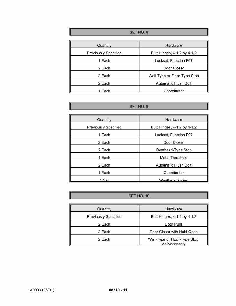
1X0000 (08/01) 08710 - 11
SET NO. 8
Quantity Hardware
Previously Specified Butt Hinges, 4-1/2 by 4-1/2
1 Each Lockset, Function F07
2 Each Door Closer
2 Each Wall-Type or Floor-Type Stop
2 Each Automatic Flush Bolt
1 Each Coordinator
SET NO. 9
Quantity Hardware
Previously Specified Butt Hinges, 4-1/2 by 4-1/2
1 Each Lockset, Function F07
2 Each Door Closer
2 Each Overhead-Type Stop
1 Each Metal Threshold
2 Each Automatic Flush Bolt
1 Each Coordinator
1 Set Weatherstripping
SET NO. 10
Quantity Hardware
Previously Specified Butt Hinges, 4-1/2 by 4-1/2
2 Each Door Pulls
2 Each Door Closer with Hold-Open
2 Each Wall-Type or Floor-Type Stop,As Necessary
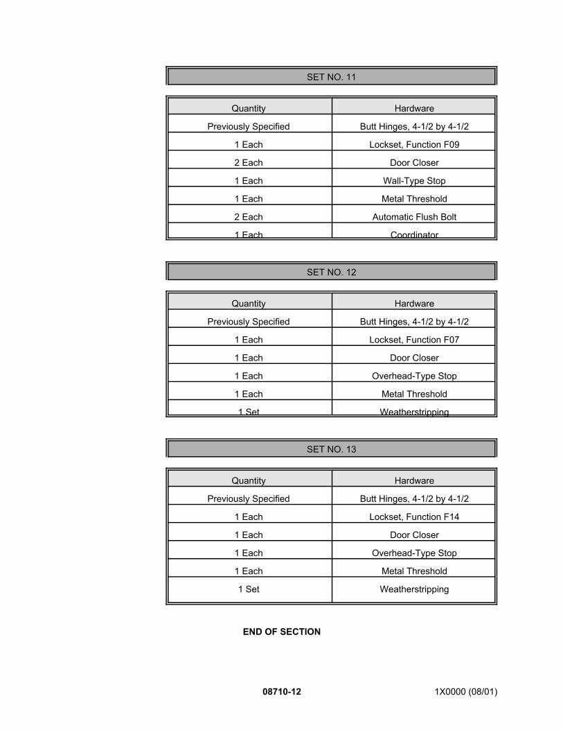
08710-12 1X0000 (08/01)
SET NO. 11
Quantity Hardware
Previously Specified Butt Hinges, 4-1/2 by 4-1/2
1 Each Lockset, Function F09
2 Each Door Closer
1 Each Wall-Type Stop
1 Each Metal Threshold
2 Each Automatic Flush Bolt
1 Each Coordinator
SET NO. 12
Quantity Hardware
Previously Specified Butt Hinges, 4-1/2 by 4-1/2
1 Each Lockset, Function F07
1 Each Door Closer
1 Each Overhead-Type Stop
1 Each Metal Threshold
1 Set Weatherstripping
SET NO. 13
Quantity Hardware
Previously Specified Butt Hinges, 4-1/2 by 4-1/2
1 Each Lockset, Function F14
1 Each Door Closer
1 Each Overhead-Type Stop
1 Each Metal Threshold
1 Set Weatherstripping
END OF SECTION

1X0000 (03/03) 08800 - 1
SECTION 08800
GLASS AND GLAZING
PART 1 - GENERAL
1.01 DESCRIPTION:
A. This section specifies providing glass and glazing (sealing) of glass areas.
B. Related Work Specified Elsewhere:1. Elevators: Division 14. *12. Granite edge: Section 04415.
1.02 QUALITY ASSURANCE:
A. Codes, Regulations, Reference Standards and Specifications:1. Comply with codes and regulations of the jurisdictional authorities.2. ANSI: Z97.1.3. ASTM: C509, C542, C864, C920, C1036, C1048, C1172, C1281, D635, D1044,
D1925, E774, E1300.4. CPSC: 16 CFR 1201, Category II.5. UL: 9, 10B.
1.03 SUBMITTALS:
A. Submit the following for approval in accordance with the General Requirements and with theadditional requirements as specified for each:1. Samples:
a. Three each of the following:1) Glass and safety plastic: 12 inches square, each material and type.2) Cast glass lens.3) Glazing compound: Pint containers.4) Setting blocks and edge blocks.5) Sealant: Cured color samples.
a) Sealant for sealing platform granite edge glass lenses:Clear silicone sealant,, one six-inch long bead.
6) Gasket material: 12 inches long.2. Certification:
a. When glass is not cut to size by manufacturer and is furnished unlabeledfrom local stock, submit certification stating location to be installed, quality,thickness, type and manufacturer of each unit of glass furnished.
b. All tempered safety and laminated tempered safety glass to be permanentlymarked with the name or trademark of the manufacturer and designation ofthe applicable safety glazing standard.
1.04 PRODUCT DELIVERY, STORAGE AND HANDLING:
A. Deliver products to the jobsite in original unopened containers clearly labeled withmanufacturer's name and brand designation, referenced specification number, type, classand rating as applicable. Deliver glass with each light bearing manufacturer's label showingstrength, grade, thickness, type, quality and safety marking. Do not remove labels from glassuntil it has been set and inspected.
08800 - 2 1X0000 (03/03)
B. Store products in approved dry area; protect from contact with soil and from exposure to theelements.
C. Handle products to prevent breakage of containers and damage to products.
1.05 JOB CONDITIONS:
A. Environmental Requirements:1. Do not install glass when the ambient temperature is below 40F or expected to fall
below 40F, unless otherwise approved.2. Do not apply glazing materials to unprotected surfaces in wet weather or to surfaces
on which ice, frost, water or dampness is visible.
PART 2 - PRODUCTS
2.01 MATERIALS:
A. Glass:1. Plate glass: ASTM C1036, Type I (transparent glass, flat), Class 1 (clear), Quality
q3.2. Safety glass: CPSC 16 CFR 1201, Category II and ANSI Z97.1 and as follows:
a. Tempered: ASTM C1048, Kind FT (fully tempered), Condition A (uncoatedsurfaces), Type I (transparent glass, flat), Class 1 (clear), Quality q3; 1/4-inch thick unless otherwise shown.
b. Laminated: ASTM C1172, Kind LT(fully tempered), 0.060-inch thickpolyvinyl-butyral (PVB) interlayer factory-laminated between two pieces oftempered safety glass with protective edgecoat on the assembly to preventcontact of interlayer with water or joint materials; edgecoat such asEdgeseal by PPG, special polyurethane seal on Solaflex glazing byMonsanto, Sommer Macca Urethane E#2 by SX Chemical Company, orequal.
c. Laminated fritted glass:1) Construction: ASTM C1172, Kind LT, Laminated glass consisting
of two pieces of fully tempered clear glass with one of the followingfritting methods to make the laminated assembly translucent but nottransparent:a) A hue-white fritted surface permanently fused onto the
laminated surface of one piece of glass with a clear 0.60-inch polyvinyl-butyral (PVB) interlayer between.
b) Two pieces of clear glass with a hue-white 0.30-inch PVBinterlayer (fritting) sandwiched between two 0.15-inch clearPVB interlayers.
2) Opacity: 80 percent coverage of translucent white fritting. Patternof fritting to be selected by the Engineer from manufacturer's wholerange of fritting patterns.
3) Provide protective edgecoat to prevent contact of interlayers withwater or joint materials.
3. Wired: ASTM C1036, Type II (wired), Class 1 (translucent), Form 1 (wired, polishedboth sides), Quality q8; Mesh m1 (diamond), unless otherwise shown.
4. Fire-rated glass (without wire): CPSC 16 CFR 1201 and ANSI Z97.1; fire-rated clearglass without wire; polished both sides.a. Rating: 45 minutes or as shown, tested in accordance with UL9 (door
assemblies) and UL10B (window assemblies).b. Label: Each piece of glass bearing UL label for fire resistance.
1X0000 (03/03) 08800 - 3
c. Thickness: As necessary to achieve the required fire rating; thicknesscoordinated with submitted shop drawings for the related doors andwindows.
d. Sources: Subject to meeting the requirements, provide one of the followingor equal:1) Premium FireLite by Nippon Electric Glass Company, Ltd. and
distributed by Technical Glass Products, Kirkland, WA; 800/426-0279.
2) Contraflam by Saint-Gobain and distributed by Euroglass GlasrepCorp., White Plains, NY; 914/683-6704.
3) Inferno-Lite by Globe Amerada Glass Co., Elk Grove Village, IL;800/323-8776.
B. Insulating Glass: ASTM E774, Class CBA; factory preassembled, sealed insulating glassunits with 1/2-inch air space; aluminum spacer tube with desiccant held captive within, anddual seal construction.1. Outer lite: 1/4-inch clear plate glass or tempered safety glass as shown or specified,
with low-emissivity (low-E) coating equal to Viracon's Solarscreen 80 on the number-two (inside) surface.
2. Inner lite: 1/4-inch clear plate glass or tempered safety glass as shown or specified.
C. Safety Plastic: Clear, monolithic polycarbonate sheet complying with the following:1. Abrasion resistance: Maximum 3.1 percent change in haze when tested in
accordance with ASTM D1044 for both surfaces.2. UV-resistance: Maximum 2.0 yellowing index after three years exposure per ASTM
D1925.3. Flammability: Meet BOCA combustibility classification C1: Horizontal burn rate of
one inch per minute or less when tested at a nominal thickness of 0.060 inch, or inthe thickness intended for use, in accordance with ASTM D635.
D. Glass Lens: Cast, clear glass, flat top with light sandblast texture, or acid etched if approved,to make it translucent, not transparent; vertical side (perimeter) roughened; top outerperimeter edge chamfered to 1/16 inch. Corning Glass Works, Pittsburgh Plate Glass Co.,Blenko Glass Company distributed by Southern Plate Glass Company, or equal. Matchtexture, quality limiting defects, and translucency of existing units within the Metro system asdirected by Engineer.1. Defects shall be limited to a maximum of six air bubbles of 3/16 inch diameter or less
with not more than three air bubbles occurring within the central three-inch diameterof lens.
2. Single-component clear silicone sealant: ASTM C920, Type S, Grade NS, Class 25,Use T; as manufactured by Dow, GE and Pecora, or approved equal.
3. Lead shims or lead rope: Section Shims die-cut from soft sheet lead; sized to suitfield conditions, generally 6-1/2 inch outside diameter, five-inch inside diameter;1/16-inch and 1/8-inch thicknesses as approved; ropes of lead wool may besubstituted for shims as approved; fabricated to ensure that glass lenses can be setflush with granite.
E. Glazing Accessories:1. Sealant: Multi-component polyurethane; ASTM C920, Type M, Grade NS, Class 25,
Use G; colored as required to match framing system in which installed.2. Glazing compound: Single-component polyurethane; ASTM C920, Type S, Grade
NS, Class 25, Use G; colored as required to match framing system in whichinstalled.
3. Glazing tape: Preformed butyl tape, ASTM C1281; 100 percent solids, nonstainingand nonmigrating in contact with nonporous surfaces; with or without spacer rod(pre-shimming) as recommended in writing by tape and glass manufacturers for

08800 - 4 1X0000 (03/03)
application indicated; packaged on rolls with a release paper backing; by 3MCompany, Tremco Manufacturing Co., or equal.
4. Pressure-sensitive tape: Vinyl electrical tape, 3M Company or equal.5. Lock-Strip Gaskets: ASTM C542 dense neoprene extrusions; profile shown or
required.6. Compression Seal Gaskets: ASTM C864 neoprene extrusions; profile and hardness
as shown or as required to maintain watertight seal.7. Setting blocks: ASTM C864 neoprene extrusions, 70-90 durometer Shore A
hardness; approximately full channel width, four inches long and high enough toafford correct cover and 3/8-inch edge clearance for the glass.
8. Edge blocks (spacers): ASTM C864 neoprene extrusions, 40-50 durometer ShoreA hardness; approximately full channel width, three inches long and providing 3/8-inch edge clearance for the glass.
9. Glazing clips and points: Type, material and quantities as required andrecommended by the manufacturers of the glazing media.
10. Glazing (face) gasket: Neoprene, formulated of compound meeting or exceedingphysical property requirements of ASTM C509, continuous, 50 durometer hardness,providing 3/16-inch face clearance inside and outside.
11. Lead-shim ring: Continuous ring of sheet lead, of thickness required to bring top ofcast glass lens level with surrounding granite.
12. Dielectric screw shield: Nylon expansion anchor, round head, sized to ensure snugfit in predrilled hole and to accommodate size of screw used.
PART 3 - EXECUTION
3.01 PREPARATION:
A. Verify dimensions before proceeding; obtain measurements at structure for work to be fittedto other construction, including wall-to-wall dimensions, floor-to-ceiling dimensions and thosecontrolled by other trades.
B. Remove dirt, dust, oil, moisture and other foreign substances from surfaces to receive glassand glazing accessories.
C. Clean glass surfaces and wipe dry.
3.02 INSTALLATION:
A. Coordinate work of this section with work of other trades.
B. Use only tempered safety glass in doors, sidelights and transoms.
C. Use only fire-rated glass in doors and windows located in fire-rated wall construction, exceptwhere wire glass is shown.
D. Size glass by measuring actual frames or sash. Sizes shown are approximate and areintended for estimating purposes only. Cut glass to form 3/8-inch bite on all sides, exceptas otherwise required by manufacturer’s product data as submitted and approved.
E. Install glass or plastic using glazing gaskets or other glazing accessories as shown.
F. Set glass on setting blocks at each quarter point of sill with equal bearing for entire width ofeach panel. Accurately cut glass to fit frames and provide smooth edges with no sharp orragged surfaces. Provide edge blocks to prevent glass from contact with side frames.

1X0000 (03/03) 08800 - 5
G. Unless otherwise shown, set glass in metal interior frames and doors or by back-face glazingwith glazing compound; tape to prevent rattling. Reset glazing beads, if necessary, withoutmarring or injuring finish.
H. Tape Glazing:1. Position tape on fixed stops so that, when compressed by glass, exposed edges of
tape are flush with or protrude slightly above sightline of stops.2. Install tape continuously, but not necessarily in one continuous length. Do not
stretch tape to make it fit opening. Do not overlap butt ends. Cut tape with sharpshears. Place joints in tape at corners of opening with adjoining lengths buttedtogether, not lapped.
3. Seal joints in tape with compatible sealant approved by tape manufacturer.4. Where framing joints are vertical, cover these joints by applying tape to head and sill
first and then to jambs. Where framing joints are horizontal, cover these joints byapplying tape to jambs and then to head and sill.
5. Place spacer or centering shims, three inches in length, 3/16 inch in height and 3/32inch in thickness, every 18 inches under tape. Hold spacers in position by gentlyplacing them in contact with underedge of tape.
6. Position setting blocks for installation of glass. Use setting blocks 1/4 inch in height.7. Do not remove release paper from tape until just before each glazing unit is installed.8. Align glass carefully to opening and press glass firmly in place. Apply removable
stops and repeat application of spacers of centering shims. Ensure that they areseated as deeply as possible in channel. Fill interior opening in conventionalmanner with glazing compound.
9. Apply cap bead of sealant over exterior exposed edge of tape.
I. Set glass in exterior metal windows and doors with neoprene setting blocks at quarter pointsand neoprene spacers two inches long placed 18 inches on center, and glaze with sealants.
J. Install glass and glazing accessories in accordance with manufacturer's recommendations.Neatly apply sealants, compounds and tapes in straight lines parallel with glazing rebates andas shown.
K. Perform direct glazing in dry weather, 40F or warmer.
L. Tape edges of laminated glass and insulating glass with pressure-sensitive tape if sealantor glazing tape is incompatible with interlayer or seals of insulating glass. Do not exposeedges of laminated glass to solvents, cleaners or prolonged contact with water.
M. Set lead-shim rings on lips at bottom of openings and glass lenses. Set glass lenses to bringflat face level with the top of granite, centered in openings. Use spacers to maintain lensesin position while filling the annular space with backer rod and sealant as shown.
3.03 INSTALLATION OF ELEVATOR HOISTWAYS:
A. Install glazing at elevator hoistways as shown and in accordance with applicablerequirements for glass and glazing.
B. Size screw holes for dielectric screw shields to permit installation so as to prevent metal-to-metal contact between screws and frame.
C. Apply sealant around entire frame, inside and outside of exterior hoistways only, and at otherareas where metals are joined resulting in unfilled space. *2

08800 - 6 1X0000 (03/03)
*1. Add 1.1 B. including 1. modification to all contracts requiring glass and glazing work for elevatorhoistways.
*2. Use first version of 3.3 C. for all contracts requiring glass and glazing work for elevator hoistways.
*3. Use second version of 3.3 C. for all contracts not requiring glass and glazing work for elevatorhoistways.
END OF SECTION
D. Apply sealant around entire frame, inside and outside, and at other areas where metals arejoined resulting in unfilled space. *3
3.04 INSTALLATION/RE-INSTALLATION OF PLATFORM GRANITE EDGE GLASS LENSES:
A. Install lead shims or lead rope.
B. Install glass lenses.
C. Apply sealant.
3.05 FIELD QUALITY CONTROL:
A. Hose Tests:1. Upon completion of glazing and sealing, perform hose test against exterior glazing
and framing members in the presence of the Engineer.2. Use 5/8-inch minimum diameter hose operated at 40-psi pressure for a minimum of
10 minutes. Repair leaks as soon as surfaces are dry; retest until approved.
B. Breakage: Prior to final acceptance, replace damaged glass.
C. Dielectric Testing:1. After installation at elevator hoistways, test for electrical isolation between screws
and hoistway metal, using ohmmeter.2. Resistance requirement: 10,000 ohms.3. Replace screws and shields that do not meet resistance requirements and retest as
for initial installation. Repeat as necessary until all screws meet resistancerequirement.
3.06 CLEAN-UP:
D. At completion of work, remove labels, except fire labels, clean glass and remove excessglazing compound and sealant from frames and surrounding finish work.
E. Remove from site rubbish and debris resulting from work of this section.
F. Leave areas surrounding work in broom-clean condition.
SEE ENDNOTES BELOW. THEY ARE AN ESSENTIAL PART OF THIS SECTION UNTIL EDITED BYSECTION DESIGNER.
ENDNOTES