Embed Size (px)
Citation preview

1Level 1: Section 05 – Version 3© 2014 SBCA
1
Section 05: Truss Materials
2
Section Downloads
Download & Print TTT I Sec 05 Slides
TTT I Sec 05 Problem Handout
TTT I Sec 05 Design Values
PS 20-2010
Non-Printable Downloads
Version 2.1
Lumber Design Values
Design Value Download
NDS Supplement
Southern Pine Council
Northeastern Lumber Manufacturers Association
Western Wood Products Association
Canadian Wood Council
3
Lumber Standard
PS 10
U.S. Department of Commerce
Voluntary
2010
4
5
Southern Pine Council
Southern Pine Use Guide
www.southernpine.com
Effective June 2012
6
Western Wood Products Association
Western Lumber Product Use Manual
www2.wwpa.org

2Level 1: Section 05 – Version 3© 2014 SBCA
7
Canadian Wood Council
The U.S. Span Book for Major Lumber Species
Major Species Combinations
Canadian U.S.
Spruce-Pine-Fir S-P-F S-P-F [S]
Douglas Fir-Larch D.Fir-L [N] D.Fir-L
Hem-Fir Hem-Fir [N] Hem-Fir
Southern Pine - SYP
www.cwc.ca/index.php/en/
8
TPI 1-2007 Selections
Selections from ANSI/TPI 1-2007
9
Standard Sizes
Table 3 – Page 8 10
Truss Materials OutlineLumber Metal Connector Plates
50% 5%
11
Lumber Outline
Wood Structure
Factors Affecting Strength
Lumber Production
Sizes & Grades
Design Values
Influences on Final Grade
12
Lumber versus Wood
Lumber & wood are not the same.
Once the shape of wood is changed, the wood is called lumber.

3Level 1: Section 05 – Version 3© 2014 SBCA
13
Wood Structure
Chemical Composition Cellulose
Lignin
Hemicellulose
Extraneous Materials Resin & Gum
14
Wood Cells
15
Growth Rings
Latewood
Earlywood16
Courtesy of Wood Engineering and Construction Handbook
Tree Parts
A = Pith
B = Wood Rays
17
Factors Affecting Wood Strength:Natural Characteristics
Direction of Wood Fibers
Specific Gravity
Moisture Content
Rate of Growth
18
Direction of Wood Fibers (Grain)

4Level 1: Section 05 – Version 3© 2014 SBCA
19
Base Values for Western Dimension Lumber
20
Specific Gravity (G)
Density = Mass Per Unit Volume
21
Moisture Content (MC)
22
Moisture Content
23
Southern Pine Design Values
Section 06 – Design Principles24
Rate of Growth

5Level 1: Section 05 – Version 3© 2014 SBCA
25
Rate of Growth
Greater # of Rings per Inch = Stronger26
Temperature
Load Duration
Chemicals
Decay Fungi
Insects
Factors Affecting Wood Strength:Environmental Characteristics
27
Temperature
Inverse relationship between strength & temperature
28
Temperature
Initial Char Rate = 1/30″ per
minute
After 8 minutes: Char Rate =
1/40″ per minute
29
Load Duration
Wood is subject to fatigue
Need to determine Load Duration Factors
Section 07 – Load Development30
Chemicals
Wood is susceptible to attack Chemicals can also help prevent attacks
Chemicals can help preserve wood & are used in fire-retardant treatments
Chemical exposure reduces strength properties Treatment manufacturers know
necessary reductions

6Level 1: Section 05 – Version 3© 2014 SBCA
31
Decay Fungi
Exposure to chronic moisture
Attack beyond the wood surface
32
Other Fungi Stain Fungi
Black Yeast
Mold Strength unaffected
Needs food, temperature, water, & air to survive Eliminate one of
these & fungi will cease
33
Facts Regarding Mold on Wood Structural Building Components TTB
TTBMOLD-D
34
Builder Advisory on Mold TTB
TTBMOLDBA-D
35
Insects
Many different types of insects attack & destroy wood
Subterranean Termites
Carpenter Ants
36
Insects
Ground SeparationDetailing
Treated Wood
7Level 1: Section 05 – Version 3© 2014 SBCA
37
Lumber Production
Lumber needs to be sized & graded
38
Kiln-Dried Lumber7% ≤ MC ≤ 19%
Lumber Production
39
Lumber Sizes
Nominal vs. Dressed Example: a nominal
sized 2x4 is actually 1.5″ x 3.5″
Lumber groups: Boards
Dimension Lumber
Timbers
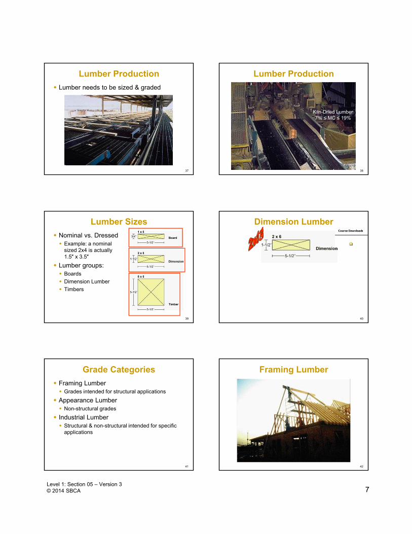
40
Dimension Lumber
41
Grade Categories
Framing Lumber Grades intended for structural applications
Appearance Lumber Non-structural grades
Industrial Lumber Structural & non-structural intended for specific
applications
42
Framing Lumber
8Level 1: Section 05 – Version 3© 2014 SBCA
43
Appearance Lumber
44
Industrial Lumber
45
Dimension Lumber Grades
46
Determining Design Values
Methods for Assigning Allowable Design Stresses to Framing Lumber Visually Graded Lumber Select Structural, No.1, No. 2, No. 3, Stud
Machine Graded Lumber MSR, MEL
47
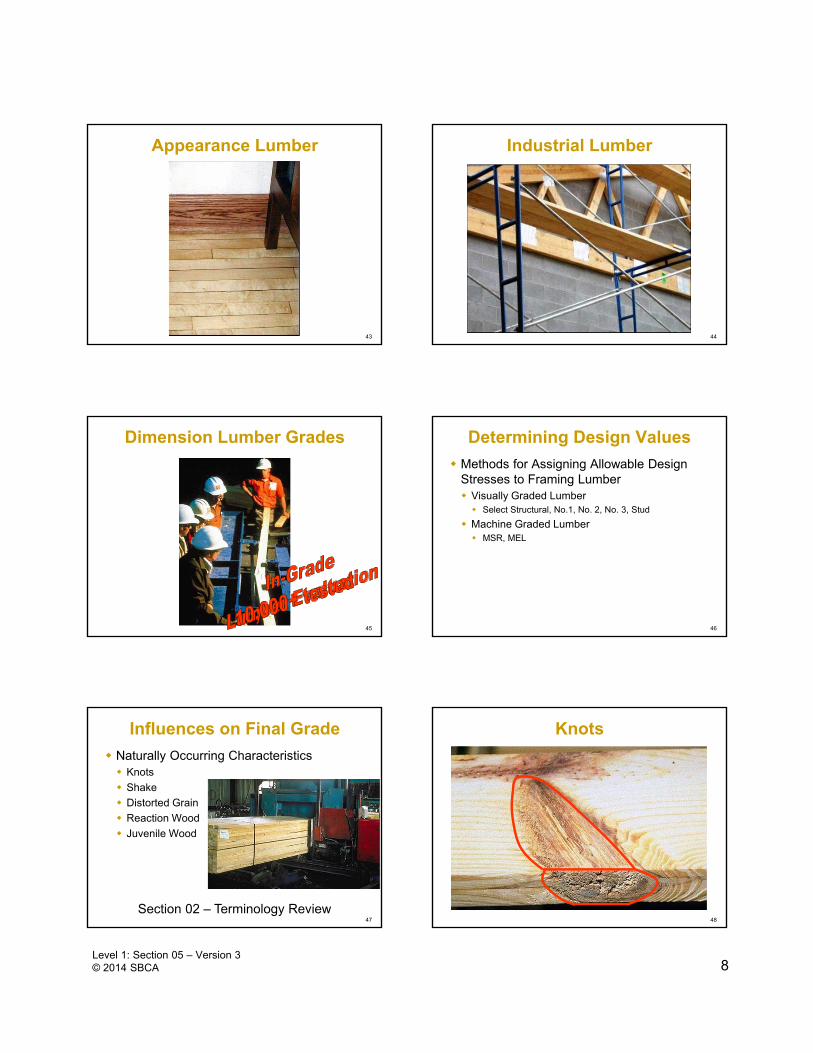
Influences on Final Grade
Naturally Occurring Characteristics Knots
Shake
Distorted Grain
Reaction Wood
Juvenile Wood
Section 02 – Terminology Review48
Knots

9Level 1: Section 05 – Version 3© 2014 SBCA
49
Shake
Sometimes the result of high winds 50
Distorted Grain
Pitch Pockets & Bark Pockets
Pitch Pockets
Bark Pockets
51
Reaction Wood
Compression Wood
52
Juvenile Wood
CROSS SECTION OF 24-YR-OLD TREE IN
UNMANAGED FOREST
CROSS SECTION OF 14-YR-OLD HIGH YIELD
FOREST TREE
Lower densityLower strength
53
Influences on Final Grade
Manufacturing Characteristics Checks
Wane
Warp
Dimensional Variability
Moisture Content
Section 02 – Terminology Review54
Checks
10Level 1: Section 05 – Version 3© 2014 SBCA
55
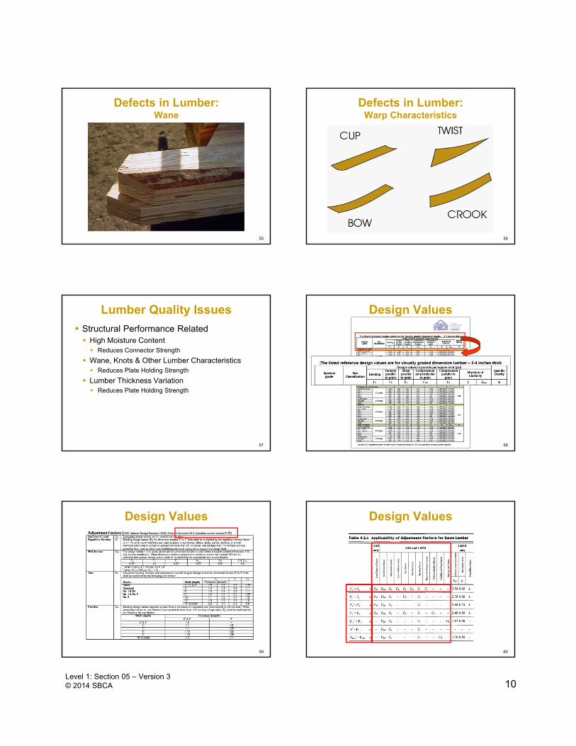
Defects in Lumber:Wane
56
Defects in Lumber:Warp Characteristics
57
Lumber Quality Issues
Structural Performance Related High Moisture Content Reduces Connector Strength
Wane, Knots & Other Lumber Characteristics Reduces Plate Holding Strength
Lumber Thickness Variation Reduces Plate Holding Strength
58
Design Values
59
Design Values Design Values
60

11Level 1: Section 05 – Version 3© 2014 SBCA
61
Design Values
Select Structural – highest visual gradeDenseSection 06 – Design PrinciplesDense, Regular, & NonDense 62
Visual Grading
Look for slope of grain, wane, knots, & distances betweenThe fewer characteristics the higher the gradeMark the grade at the end of each pieceMay mark piece to be end trimmedRipped lumber needs to be re-graded
63
Visual Grade Stamp
Species?64
Visually Graded Lumber
Select-Structural
No. 1
No. 2
No. 3
Watch as lumber characteristics become more pronounced as grades decrease
65
Visually Graded Lumber:Select Structural
66
Visually Graded Lumber:No. 1

12Level 1: Section 05 – Version 3© 2014 SBCA
67
Visually Graded Lumber:No. 2
68
Visually Graded Lumber:No. 3
69
Machine Graded Lumber
Machine Stress Rated (MSR) Grades Designated by Fb and E
Machine Evaluated Lumber (MEL) Grades Designated by Numerical Designation
“M-xx”
Bending stress = 1650 psiModulus of Elasticity = 1,500,000 psi
70
Machine Graded Lumber
Shear parallel to grain (Fv) and Compression Perpendicular to Grain (Fc┴) depend on species & grade
71
Machine Grading Technologies
Continuous Lumber Tester (CLT)
Directly measures the stiffness of lumber
X-ray Lumber Gauge (XLG)
Directly measures the density of lumber
72
Continuous Lumber Tester (CLT)

13Level 1: Section 05 – Version 3© 2014 SBCA
73
X-Ray Lumber Gauge (XLG)
74
Technologies and Types
Both CLT & XLG can be used in the production of MSR & MEL
75
Machine Graded Lumber
Section 06 – Design Principles
Ft = Tensile Stress Parallel-to-Grain SG = Specific Gravity
Fv = Horizontal Shear
Fc┴ = Compression Stress Perpendicular-to-Grain
76
Lumber Grades TTB
TTBGRADES-D
77
Quiz 1
78
Metal Connector Plates Outline
How Plates Work
Plate Testing Lateral Resistance
Strength
Shear Net Section
Tension Net Section
Full Scale Testing
Early Truss Testing
Example Problem

14Level 1: Section 05 – Version 3© 2014 SBCA
79
Metal Connector Plates
Structurally SafeEfficient
Easy to Install
80
How Connector Plates Work
Sufficiently sized plates are placed on both sides of joint
Plates are pressed into wood
Plates resist forces at joints by transferring them from lumber through teeth & into plate
81
How Connector Plates Work
82
Metal Connector Plate Testing
Capacities measured in terms of withdrawal strength
Each plate manufacturer has its own truss plate design & associated strength values
Plate manufacturers test their plates & register results with evaluation agencies
Section 02 – Terminology
83
Testing Standard
Work began in 1959
1st Standard developed by TPI in 1960 TPI-60 “Design Specification for Light Metal Plate
Connected Timber Trusses”
Ten editions: 1962 to 2007
84
Strength Properties Tested

15Level 1: Section 05 – Version 3© 2014 SBCA
85
Strength Properties Tested
Lateral Resistance Strength Tooth Withdrawal
Shear Net Section
Tension Net Section
86
Lateral Strength Tests
TPI 1 requires the evaluation of truss plates in four orientations. Connector plate length parallel-to-load, parallel-to-
grain (LRAA).
87
Lateral Strength Tests
Connector plate length perpendicular-to-load, parallel-to-grain (LREA).
88
Lateral Strength Tests
Connector plate length parallel-to-load, perpendicular-to-grain (LRAE).
89
Lateral Strength Tests
Connector plate length perpendicular-to-load, perpendicular-to-grain (LREE).
90
Lateral Strength Tests At Critical Slip, divide
the load by 1.3.
Average the test values for each plate orientation & multiply by a specific gravity average.

16Level 1: Section 05 – Version 3© 2014 SBCA
91
Lateral Strength Tests At Ultimate Failure,
divide the load by 3.2.
Average the test values for each plate orientation & multiply by a specific gravity average.
92
Shear Strength Tests
93
Shear Net Section
94
Tensile Strength Tests
95
Shear Failure
96
Full Scale Testing

17Level 1: Section 05 – Version 3© 2014 SBCA
97
Full Scale Testing
98
Full Scale Testing
99
Full Scale System Testing
100
Early Truss Tests
101
Early Truss Tests
102
Quiz 2

18Level 1: Section 05 – Version 3© 2014 SBCA
103
TTT 1 Sec 05 Handout
TTT 1 Sec 05 Handout
104
Given Situation
You = Truss Manufacture
Structure in Madison, WI
Builder calls about “truss uplift” problem
Constructed during rain last summer
It is now February
105
Given Situation
Floor joist & interior wall lumber was installed with 25% MC
Lumber has dried to 8% MC
Floor joists Douglas Fir-Larch
Studs & plate material SPF (south)
SPF (south)
Doug Fir-
Larch
106
Given Situation
≈ 1” gap between top of 3rd floor wall & truss BC
Gap increased over time
Trusses “arch” Must be the problem
107
Questions
(a) Do you agree or disagree? Why or why not?
(b) Assuming that there has been no foundation settlement, what check should be made on the trusses to prove or disprove the builder’s claim?
108
Answers
(a) Disagree! Truss arching is typically a temporary condition Open/close NOT progressively worse
Progressively worse gap indicates settlement
MC 25% to 8%
Wood shrinkage
19Level 1: Section 05 – Version 3© 2014 SBCA
109
Lumber Shrinkage
110
Partition Separation Prevention & Solutions TTB
TTBPARTSEP-D
111
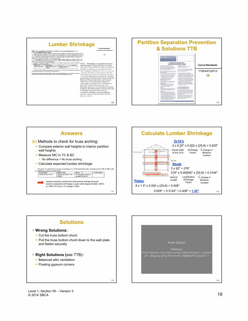
Answers
(b) Methods to check for truss arching: Compare exterior wall heights to interior partition
wall heights
Measure MC in TC & BC No difference = No truss arching
Calculate expected lumber shrinkage
Vertical members exhibit less dimensional change because wood’s longitudinal shrinkage is quite small (approximately .003% to .006% for every 1% change in MC).
112
Calculate Lumber Shrinkage2x10′s
Studs
Plates
2 x 9.25" x 0.002 x (25-8) = 0.629"Actual width of dry 2x10
Shrinkage Factor
% change in Moisture Content
3 x 92" = 276"
276" x 0.000067 x (25-8) = 0.3144"
Vertical Length
Longitudinal Shrinkage
Factor
% change in Moisture Content
8 x 1.5" x 0.002 x (25-8) = 0.408"
0.629" + 0.3144" + 0.408" = 1.35"
Solutions
Wrong Solutions: Cut the truss bottom chord
Pull the truss bottom chord down to the wall plate and fasten securely
Right Solutions (see TTB): Balanced attic ventilation
Floating gypsum corners
113 114
Quiz 3

20Level 1: Section 05 – Version 3© 2014 SBCA
115
Feedback