Embed Size (px)
Citation preview
02-202.40/ 1FRONT DOOR OPERATOR 20
21M
R08
REVISION HISTORYDate Author Change Description
2017-12-01 DJL Renumbered 02-210.02 to 02-202.51 and extracted handle information, as well as information relative to door controller.(02-202.40).
2018-04-06 SP Added operation, connecting rod adjustment material and front door verification from 02-202.50
2021-03-08 HB Added door position proximity sensor details.
SECTION 02-202.40FRONT DOOR OPERATOR

2 /02-202.40FRONT DOOR OPERATOR20
21M
R08
BLANK PAGE
02-202.40/ 3FRONT DOOR OPERATOR 20
21M
R08
OPERATIONNOTE
The opening and closing times of the panels vary according to the programming of the vehicle.
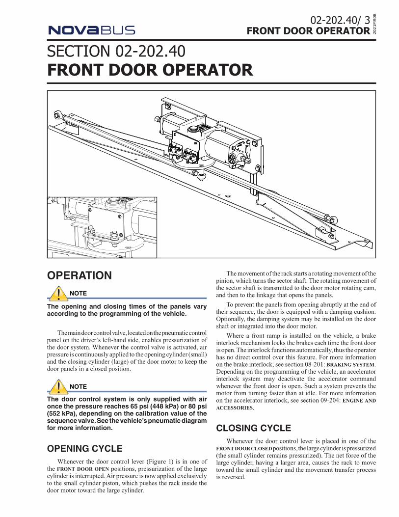
The main door control valve, located on the pneumatic control panel on the driver’s left-hand side, enables pressurization of the door system. Whenever the control valve is activated, air pressure is continuously applied to the opening cylinder (small) and the closing cylinder (large) of the door motor to keep the door panels in a closed position.
NOTE
The door control system is only supplied with air once the pressure reaches 65 psi (448 kPa) or 80 psi (552 kPa), depending on the calibration value of the sequence valve. See the vehicle’s pneumatic diagram for more information.
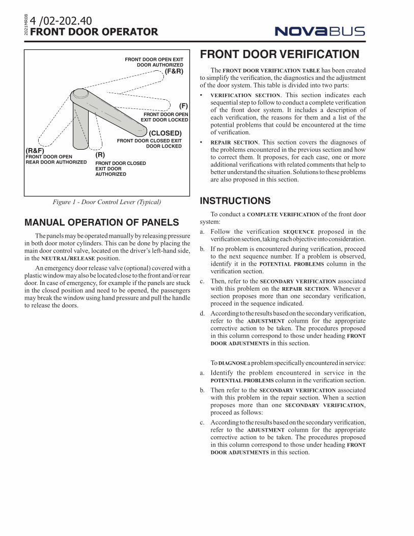
OPENING CYCLEWhenever the door control lever (Figure 1) is in one of
the front door open positions, pressurization of the large cylinder is interrupted. Air pressure is now applied exclusively to the small cylinder piston, which pushes the rack inside the door motor toward the large cylinder.
SECTION 02-202.40FRONT DOOR OPERATOR
The movement of the rack starts a rotating movement of the pinion, which turns the sector shaft. The rotating movement of the sector shaft is transmitted to the door motor rotating cam, and then to the linkage that opens the panels.
To prevent the panels from opening abruptly at the end of their sequence, the door is equipped with a damping cushion. Optionally, the damping system may be installed on the door shaft or integrated into the door motor.
Where a front ramp is installed on the vehicle, a brake interlock mechanism locks the brakes each time the front door is open. The interlock functions automatically, thus the operator has no direct control over this feature. For more information on the brake interlock, see section 08-201: braking system. Depending on the programming of the vehicle, an accelerator interlock system may deactivate the accelerator command whenever the front door is open. Such a system prevents the motor from turning faster than at idle. For more information on the accelerator interlock, see section 09-204: engine and accessories.
CLOSING CYCLEWhenever the door control lever is placed in one of the
front door closed positions, the large cylinder is pressurized (the small cylinder remains pressurized). The net force of the large cylinder, having a larger area, causes the rack to move toward the small cylinder and the movement transfer process is reversed.
4 /02-202.40FRONT DOOR OPERATOR20
21M
R08
MANUAL OPERATION OF PANELSThe panels may be operated manually by releasing pressure
in both door motor cylinders. This can be done by placing the main door control valve, located on the driver’s left-hand side, in the neutral/release position.
An emergency door release valve (optional) covered with a plastic window may also be located close to the front and/or rear door. In case of emergency, for example if the panels are stuck in the closed position and need to be opened, the passengers may break the window using hand pressure and pull the handle to release the doors.
FRONT DOOR OPEN EXIT DOOR AUTHORIZED
(F&R)
FRONT DOOR CLOSEDEXIT DOOR AUTHORIZED
(R)
FRONT DOOR OPENEXIT DOOR LOCKED
(F)
(CLOSED)FRONT DOOR CLOSED EXIT
DOOR LOCKED
Figure 1 - Door Control Lever (Typical)
(R&F)FRONT DOOR OPEN REAR DOOR AUTHORIZED
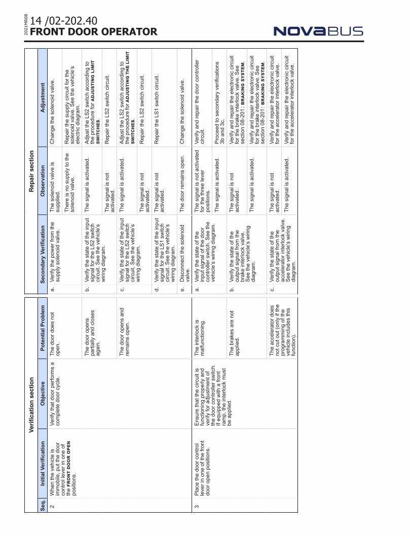
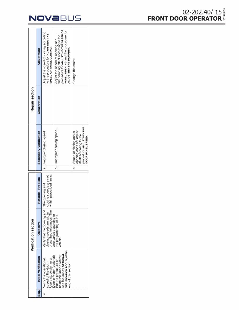
FRONT DOOR VERIFICATIONThe front door verification table has been created
to simplify the verification, the diagnostics and the adjustment of the door system. This table is divided into two parts:
• verification section. This section indicates each sequential step to follow to conduct a complete verification of the front door system. It includes a description of each verification, the reasons for them and a list of the potential problems that could be encountered at the time of verification.
• repair section. This section covers the diagnoses of the problems encountered in the previous section and how to correct them. It proposes, for each case, one or more additional verifications with related comments that help to better understand the situation. Solutions to these problems are also proposed in this section.
INSTRUCTIONSTo conduct a complete verification of the front door
system:
a. Follow the verification sequence proposed in the verification section, taking each objective into consideration.
b. If no problem is encountered during verification, proceed to the next sequence number. If a problem is observed, identify it in the potential problems column in the verification section.
c. Then, refer to the secondary verification associated with this problem on the repair section. Whenever a section proposes more than one secondary verification, proceed in the sequence indicated.
d. According to the results based on the secondary verification, refer to the adjustment column for the appropriate corrective action to be taken. The procedures proposed in this column correspond to those under heading front door adjustments in this section.
To diagnose a problem specifically encountered in service:
a. Identify the problem encountered in service in the potential problems column in the verification section.
b. Then refer to the secondary verification associated with this problem in the repair section. When a section proposes more than one secondary verification, proceed as follows:
c. According to the results based on the secondary verification, refer to the adjustment column for the appropriate corrective action to be taken. The procedures proposed in this column correspond to those under heading front door adjustments in this section.
02-202.40/ 5FRONT DOOR OPERATOR 20
21M
R08
ADJUSTMENTSADJUSTING THE CONNECTING RODS
NOTE
While tightening or loosening a connecting rod, always use two wrenches, one to hold the rod, and the other for the ball joint stem locknut, thereby avoiding the forcing of the rod and ball joint.
1. Cut off the air supply to the door system.
2. On each rod, unscrew both ball joint stem locknuts. See Figure 2.
3. Disconnect each connecting rod from the door shaft lever. See Figure 2.
4. On each rod, completely tighten each ball joint by holding the ball joint in position and turning the rod.
5. On each rod, loosen each ball joint approximately 3/4 in. (2 cm) while still holding the ball joint in position and turning the rod. Keep a constant tension on each, but do not turn the motor cam of the door. The threads must number the same at both ends. See Figure 2.
CAUTION
Do not apply too much tension, nor permit too much play on the rods. The threaded ends of the rods could be damaged during operation of the door mechanism.
6. Center the limit switches on their mounting plate.Using the limit switch’s adjustment screws, adjust the switches in such a way to respect distances in Figure 3. Retighten the adjustment screws to the torque value specified in Figure 8.
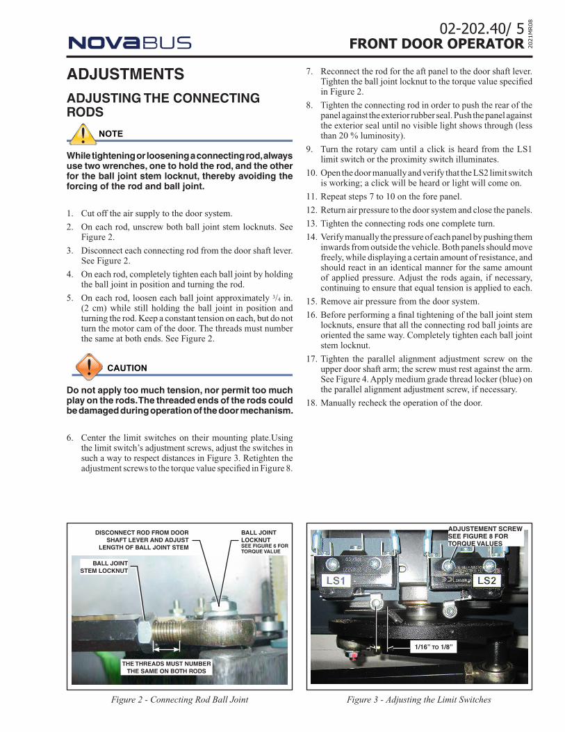
Figure 3 - Adjusting the Limit SwitchesFigure 2 - Connecting Rod Ball Joint
DISCONNECT ROD FROM DOOR SHAFT LEVER AND ADJUST
LENGTH OF BALL JOINT STEM
BALL JOINT STEM LOCKNUT
THE THREADS MUST NUMBER THE SAME ON BOTH RODS
BALL JOINT LOCKNUTSEE FIGURE 6 FOR TORQUE VALUE
7. Reconnect the rod for the aft panel to the door shaft lever. Tighten the ball joint locknut to the torque value specified in Figure 2.
8. Tighten the connecting rod in order to push the rear of the panel against the exterior rubber seal. Push the panel against the exterior seal until no visible light shows through (less than 20 % luminosity).
9. Turn the rotary cam until a click is heard from the LS1 limit switch or the proximity switch illuminates.
10. Open the door manually and verify that the LS2 limit switch is working; a click will be heard or light will come on.
11. Repeat steps 7 to 10 on the fore panel.
12. Return air pressure to the door system and close the panels.
13. Tighten the connecting rods one complete turn.
14. Verify manually the pressure of each panel by pushing them inwards from outside the vehicle. Both panels should move freely, while displaying a certain amount of resistance, and should react in an identical manner for the same amount of applied pressure. Adjust the rods again, if necessary, continuing to ensure that equal tension is applied to each.
15. Remove air pressure from the door system.
16. Before performing a final tightening of the ball joint stem locknuts, ensure that all the connecting rod ball joints are oriented the same way. Completely tighten each ball joint stem locknut.
17. Tighten the parallel alignment adjustment screw on the upper door shaft arm; the screw must rest against the arm. See Figure 4. Apply medium grade thread locker (blue) on the parallel alignment adjustment screw, if necessary.
18. Manually recheck the operation of the door.
ADJUSTEMENT SCREWSEE FIGURE 8 FOR TORQUE VALUES
1/16’’ to 1/8’’
6 /02-202.40FRONT DOOR OPERATOR20
21M
R08
ADJUSTING LIMIT SWITCHES1. Make sure air is applied to door system. Position door
control lever in the door close position.
2. Adjust limit switch LS1 for the door close signal. Loosen both Philips head screws to allow lateral movement. Place switch roller between 1/16“ and 1/8” from the end of the teeter plate cam. See Figure 3.
3. Tighten LS1 attachment screws. See Figure 8
4. Place door control lever in the rear door open position.
5. Adjust limit switch LS2 for the door open signal. Loosen both Philips head screws to allow lateral movement. Place switch roller between 1/16“ and 1/8” from the end of the teeter plate cam. See Figure 3.
6. Tighten LS2 attachment screws. See Figure 8
DOOR MOTOR PROXIMITY SWITCH (IF EQUIPPED)
VERIFIYING THE SWITCHES
1. Close the panels completely.
2. Verify the contacts of the switches.
- LS1 – NO – DFC Contact closed
- LS2 – NO – DFO Contact open
3. If the LS1 switch is not actuated or if the switch was previously removed, adjust according to the ADJUSTING THE LS1 SWITCH heading.
4. Open the panels completely.
5. Verify the contacts of the switches:
- LS1 – NO – DFC Contact open
- LS2 – NO – DFO Contact closed
6. If the LS2 switch is not adjusted properly, or if the switch was previously removed, adjust according to the ADJUSTING THE LS2 SWITCH heading.
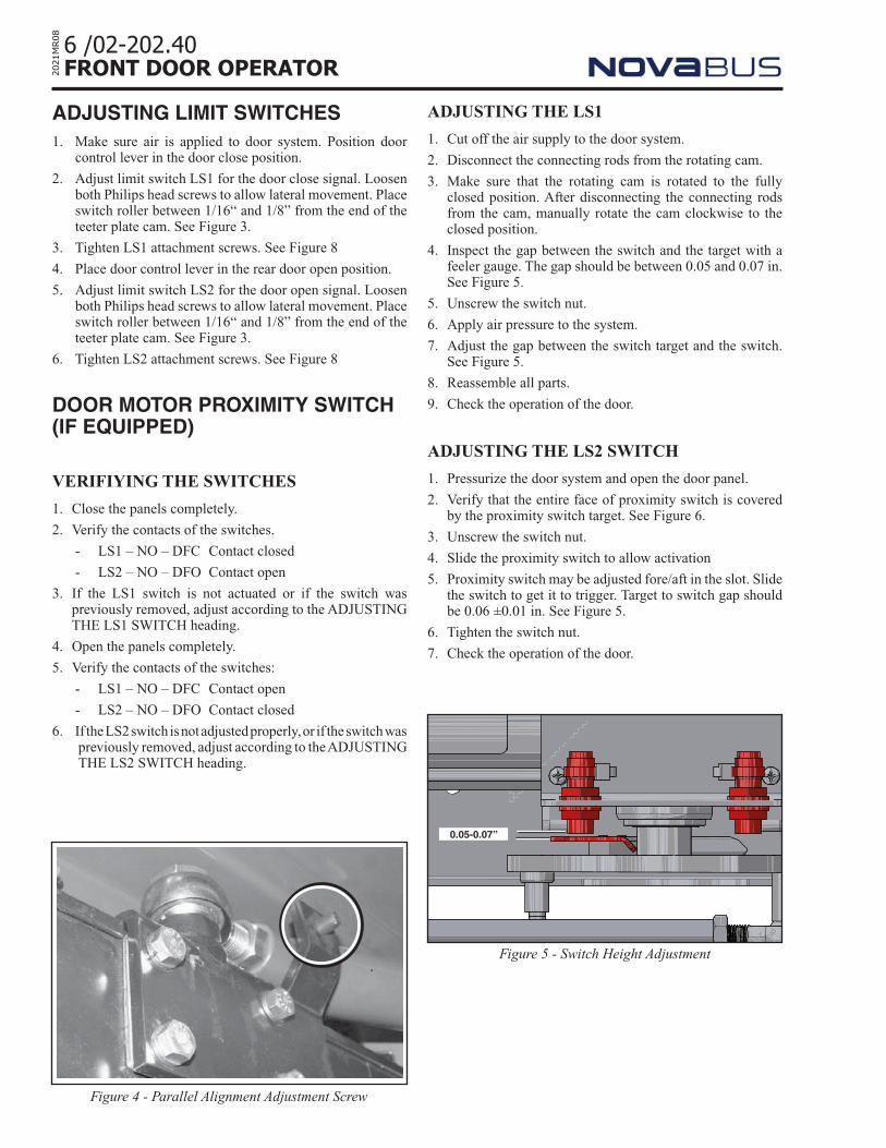
Figure 4 - Parallel Alignment Adjustment Screw
ADJUSTING THE LS1
1. Cut off the air supply to the door system.
2. Disconnect the connecting rods from the rotating cam.
3. Make sure that the rotating cam is rotated to the fully closed position. After disconnecting the connecting rods from the cam, manually rotate the cam clockwise to the closed position.
4. Inspect the gap between the switch and the target with a feeler gauge. The gap should be between 0.05 and 0.07 in. See Figure 5.
5. Unscrew the switch nut.
6. Apply air pressure to the system.
7. Adjust the gap between the switch target and the switch. See Figure 5.
8. Reassemble all parts.
9. Check the operation of the door.
ADJUSTING THE LS2 SWITCH
1. Pressurize the door system and open the door panel.
2. Verify that the entire face of proximity switch is covered by the proximity switch target. See Figure 6.
3. Unscrew the switch nut.
4. Slide the proximity switch to allow activation
5. Proximity switch may be adjusted fore/aft in the slot. Slide the switch to get it to trigger. Target to switch gap should be 0.06 ±0.01 in. See Figure 5.
6. Tighten the switch nut.
7. Check the operation of the door.
0.05-0.07’’
Figure 5 - Switch Height Adjustment
02-202.40/ 7FRONT DOOR OPERATOR 20
21M
R08
SPEED OF PANEL CLOSING
3. If the measured closing speed is not within prescribed tolerances, adjust the panel closing speed by turning the closing speed adjustment screw. See Figure 7.
a. Loosen the adjustment screw locknut.
b. Screw in the adjustment screw to slow down the closing of the panels and unscrew the screw to increase the panel closing speed.
4. Measure the speed of panel closing using a stopwatch or a Door-o-Meter.
If the measured time is again not within accepted tolerances, repeat the adjustment.
5. Tighten the locknut while ensuring that the adjustment screw maintains its setting. Ensure that the locknut is well tightened.
6. Recheck the time taken for panel closing and, if necessary, readjust.
SPEED OF PANEL OPENING
NOTE
When calculating the opening time of the door, allow 3 seconds to pass after the closing of the door between each test. This permits the application of maximum pressure to the door and has an affect on the damping at the end of the door cycle.
7. Close the door panels.
8. Measure the speed of panel opening using a stopwatch or a Door-o-Meter.
9. If the measured opening speed is not within prescribed tolerances, adjust the speed of opening of the panels by turning the opening speed adjustment screw. See Figure 7.
a. Loosen the adjustment screw locknut.
b. Screw in the adjustment screw to slow down the opening of the panels and unscrew the screw to increase the panel opening speed.
10. Measure the speed of panel opening using a stopwatch or a Door-o-Meter.
If the measured time is again not within accepted tolerances, repeat the adjustment.
11. Tighten the locknut while ensuring that the adjustment screw maintains its setting. Ensure that the locknut is well tightened.
12. Recheck the time taken for panel closing and, if necessary, readjust.
13. If the opening speed adjustment has been completed, conduct the adjusting the damping.
ADJUSTING THE DOOR PANEL SPEED
NOTE
Before proceeding, ensure that the telescopic stanchion (optional) is attached on both sides, since it influences the opening and closing times of the panels. Also ensure that the stanchion joints are parallel to the floor.
1. Activate the door and verify the time that it takes for the door panels to open and close using a stopwatch or a Door-o-Meter.
2. Before commencing the adjustment for the closing and the opening, loosen the damping adjustment screw. See Figure 7.
CAUTION
To obtain a precise adjustment, it is necessary to adjust the panel speed in the following order:
1. Speed of panel closing2. Speed of panel opening3. Damping
CAUTION
When making adjustments, never force the adjustment screws in a clockwise direction. The excessive tightening pressure will damage the motor cylinder cap.
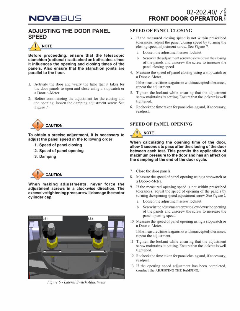
LS1 LS2
Figure 6 - Lateral Switch Adjustment
8 /02-202.40FRONT DOOR OPERATOR20
21M
R08
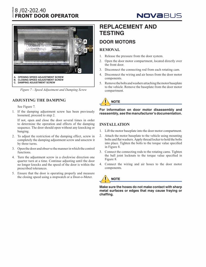
ADJUSTING THE DAMPING
See Figure 7.
1. If the damping adjustment screw has been previously loosened, proceed to step 2.
If not, open and close the door several times in order to determine the operation and effects of the damping sequence. The door should open without any knocking or banging.
2. To adjust the restriction of the damping effect, screw in completely the damping adjustment screw and unscrew it by three turns.
3. Open the door and observe the manner in which the control functions.
4. Turn the adjustment screw in a clockwise direction one quarter turn at a time. Continue adjusting until the door no longer knocks and the speed of the door is within the prescribed tolerances.
5. Ensure that the door is operating properly and measure the closing speed using a stopwatch or a Door-o-Meter.
REPLACEMENT AND TESTINGDOOR MOTORS
REMOVAL
1. Release the pressure from the door system.
2. Open the door motor compartment, located directly over the front door.
3. Disconnect the connecting rod from each rotating cam.
4. Disconnect the wiring and air hoses from the door motor components.
5. Remove the bolts and washers attaching the motor baseplate to the vehicle. Remove the baseplate from the door motor compartment.
NOTE
For information on door motor disassembly and reassembly, see the manufacturer’s documentation.
INSTALLATION
1. Lift the motor baseplate into the door motor compartment.
2. Attach the motor baseplate to the vehicle using mounting bolts and flat washers. Apply thread locker to hold the bolts into place. Tighten the bolts to the torque value specified in Figure 8.
3. Connect the connecting rods to the rotating cams. Tighten the ball joint locknuts to the torque value specified in Figure 8.
4. Connect the wiring and air hoses to the door motor components.
NOTE
Make sure the hoses do not make contact with sharp metal surfaces or edges that may cause fraying or chaffing.
Figure 7 - Speed Adjustment and Damping Screw
A. OPENING SPEED ADJUSTMENT SCREWB. CLOSING SPEED ADJUSTMENT SCREWC. DAMPING ADJUSTMENT SCREW
A
B
C
02-202.40/ 9FRONT DOOR OPERATOR 20
21M
R08
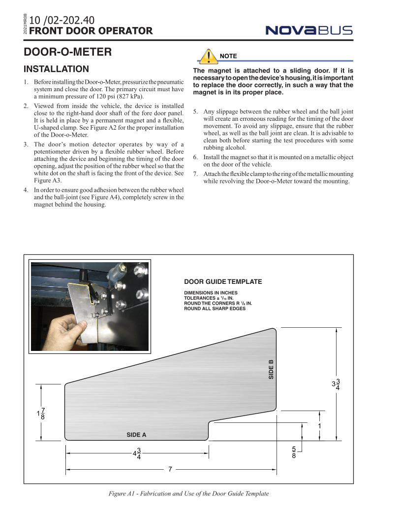
USEPress side a of the template on the panel, along the roller
support, and side b on the underside of the roller.
Make sure that side a and side b of the template are fully pressed against their respective surfaces. If they are completely pressed, the roller support is perpendicular to the top of the panel. See Figure A1.
23
1
4
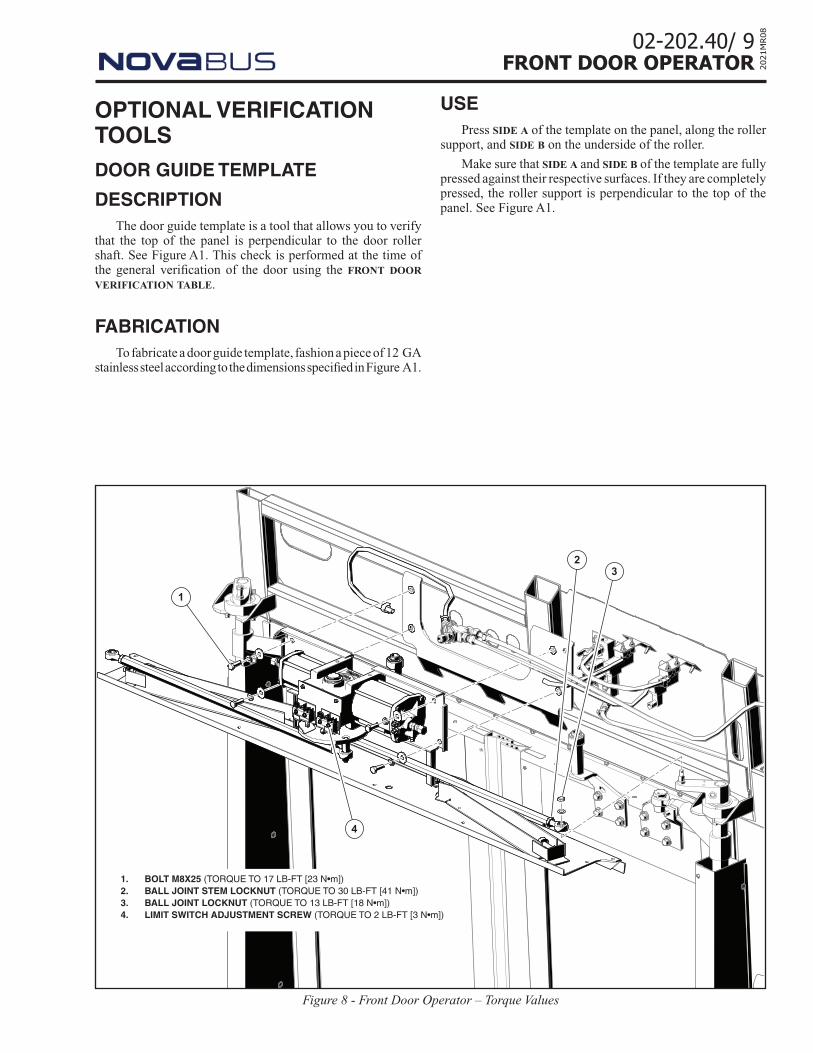
Figure 8 - Front Door Operator – Torque Values
1. BOLT M8X25 (TORQUE TO 17 LB-FT [23 N•m])2. BALL JOINT STEM LOCKNUT (TORQUE TO 30 LB-FT [41 N•m])3. BALL JOINT LOCKNUT (TORQUE TO 13 LB-FT [18 N•m])4. LIMIT SWITCH ADJUSTMENT SCREW (TORQUE TO 2 LB-FT [3 N•m])
OPTIONAL VERIFICATION TOOLS DOOR GUIDE TEMPLATE
DESCRIPTIONThe door guide template is a tool that allows you to verify
that the top of the panel is perpendicular to the door roller shaft. See Figure A1. This check is performed at the time of the general verification of the door using the front door verification table.
FABRICATIONTo fabricate a door guide template, fashion a piece of 12 GA
stainless steel according to the dimensions specified in Figure A1.
10 /02-202.40FRONT DOOR OPERATOR20
21M
R08
DOOR-O-METERINSTALLATION1. Before installing the Door-o-Meter, pressurize the pneumatic
system and close the door. The primary circuit must have a minimum pressure of 120 psi (827 kPa).
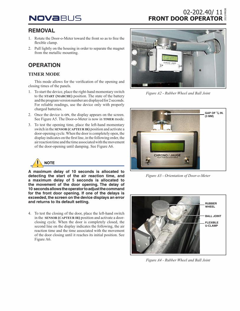
2. Viewed from inside the vehicle, the device is installed close to the right-hand door shaft of the fore door panel. It is held in place by a permanent magnet and a flexible, U-shaped clamp. See Figure A2 for the proper installation of the Door-o-Meter.
3. The door’s motion detector operates by way of a potentiometer driven by a flexible rubber wheel. Before attaching the device and beginning the timing of the door opening, adjust the position of the rubber wheel so that the white dot on the shaft is facing the front of the device. See Figure A3.
4. In order to ensure good adhesion between the rubber wheel and the ball-joint (see Figure A4), completely screw in the magnet behind the housing.
NOTE
The magnet is attached to a sliding door. If it is necessary to open the device’s housing, it is important to replace the door correctly, in such a way that the magnet is in its proper place.
5. Any slippage between the rubber wheel and the ball joint will create an erroneous reading for the timing of the door movement. To avoid any slippage, ensure that the rubber wheel, as well as the ball joint are clean. It is advisable to clean both before starting the test procedures with some rubbing alcohol.
6. Install the magnet so that it is mounted on a metallic object on the door of the vehicle.
7. Attach the flexible clamp to the ring of the metallic mounting while revolving the Door-o-Meter toward the mounting.
1 78
7
434
1
334
58
Figure A1 - Fabrication and Use of the Door Guide Template
DOOR GUIDE TEMPLATE
DIMENSIONS IN INCHESTOLERANCES ± 1/16 IN.ROUND THE CORNERS R 1/8 IN.ROUND ALL SHARP EDGES
SID
E B
SIDE A
02-202.40/ 11FRONT DOOR OPERATOR 20
21M
R08
REMOVAL1. Rotate the Door-o-Meter toward the front so as to free the
flexible clamp.
2. Pull lightly on the housing in order to separate the magnet from the metallic mounting.
OPERATION
TIMER MODE
This mode allows for the verification of the opening and closing times of the panels.
1. To start the device, place the right-hand momentary switch to the start (marche) position. The state of the battery and the program version number are displayed for 2 seconds. For reliable readings, use the device only with properly charged batteries.
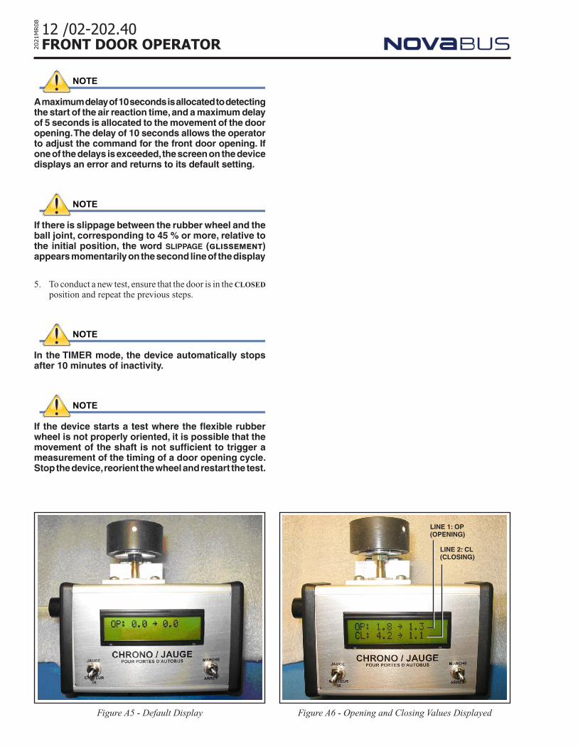
2. Once the device is on, the display appears on the screen. See Figure A5. The Door-o-Meter is now in timer mode.
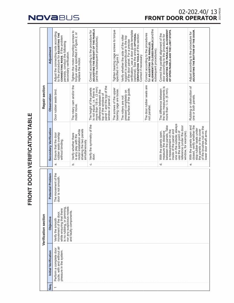
3. To test the opening time, place the left-hand momentary switch in the sensor (capteur ir) position and activate a door-opening cycle. When the door is completely open, the display indicates on the first line, in the following order, the air reaction time and the time associated with the movement of the door-opening until damping. See Figure A6.
NOTE
A maximum delay of 10 seconds is allocated to detecting the start of the air reaction time, and a maximum delay of 5 seconds is allocated to the movement of the door opening. The delay of 10 seconds allows the operator to adjust the command for the front door opening. If one of the delays is exceeded, the screen on the device displays an error and returns to its default setting.
4. To test the closing of the door, place the left-hand switch in the sensor (capteur ir) position and activate a door-closing cycle. When the door is completely closed, the second line on the display indicates the following, the air reaction time and the time associated with the movement of the door closing until it reaches its initial position. See Figure A6.
Figure A3 - Orientation of Door-o-Meter
GAP OF 1/8 IN. (3 MM)
Figure A2 - Rubber Wheel and Ball Joint
RUBBER WHEEL
Figure A4 - Rubber Wheel and Ball Joint
BALL JOINT
FLEXIBLE U-CLAMP
12 /02-202.40FRONT DOOR OPERATOR20
21M
R08
NOTE
A maximum delay of 10 seconds is allocated to detecting the start of the air reaction time, and a maximum delay of 5 seconds is allocated to the movement of the door opening. The delay of 10 seconds allows the operator to adjust the command for the front door opening. If one of the delays is exceeded, the screen on the device displays an error and returns to its default setting.
NOTE
If there is slippage between the rubber wheel and the ball joint, corresponding to 45 % or more, relative to the initial position, the word slippage (glissement) appears momentarily on the second line of the display
5. To conduct a new test, ensure that the door is in the closed position and repeat the previous steps.
NOTE
In the TIMER mode, the device automatically stops after 10 minutes of inactivity.
NOTE
If the device starts a test where the flexible rubber wheel is not properly oriented, it is possible that the movement of the shaft is not sufficient to trigger a measurement of the timing of a door opening cycle. Stop the device, reorient the wheel and restart the test.
Figure A5 - Default Display
LINE 1: OP (OPENING)
LINE 2: CL (CLOSING)
Figure A6 - Opening and Closing Values Displayed
02-202.40/ 13FRONT DOOR OPERATOR 20
21M
R08
FR
ON
T D
OO
R V
ER
IFIC
AT
ION
TA
BL
E
Ver
ifica
tio
n s
ecti
on
Rep
air
sect
ion
Seq.
Initi
al V
erifi
catio
nO
bjec
tive
Pote
ntia
l Pro
blem
Seco
ndar
y Ve
rifica
tion
Obs
erva
tion
Adj
ustm
ent
1Pe
rform
a c
ompl
ete
door
cy
cle,
with
and
with
out a
ir pr
essu
re in
the
syst
em.
Verif
y th
e sm
ooth
m
ovem
ent o
f the
doo
r, w
hile
ens
urin
g th
at th
ere
is n
o ru
bbin
g, o
r jam
min
g,
nor a
ny s
uspi
ciou
s no
ises
an
d fa
ulty
com
pone
nts.
The
mov
emen
t of t
he
door
is n
ot s
moo
th.
a.En
sure
that
the
door
ru
bber
sea
ls o
verla
p w
ithou
t bin
ding
.
Doo
r rub
ber s
eals
bin
d.Ad
just
the
conn
ectin
g ro
ds a
ccor
ding
to
the
proc
edur
e fo
r adj
usti
ng t
he
conn
ecti
ng r
ods.
If th
e pr
oble
m
pers
ists
, con
duct
the
follo
win
g se
cond
ary
verifi
catio
n.
b.Ve
rify
whe
ther
ther
e is
any
pla
y w
ith th
e m
otor
inst
alla
tion
whi
le
shak
ing
the
two
pane
ls
sim
ulta
neou
sly.
The
rota
ry c
am a
nd/o
r the
m
otor
mov
e.Ti
ghte
n th
e m
otor
mou
ntin
g sc
rew
s to
to
rque
val
ue s
peci
fied
in F
igur
e 2,
or
repl
ace
the
mot
or.
c.Ve
rify
the
sym
met
ry o
f the
do
or.
The
heig
ht o
f the
pan
els
is n
ot e
qual
, i.e
. the
re is
m
ore
than
1/8
in. (
3 m
m)
diffe
renc
e be
twee
n th
e to
p of
the
win
dow
of
pane
l 1 a
nd th
e to
p of
the
win
dow
of p
anel
2.
Cor
rect
acc
ordi
ng to
the
proc
edur
e fo
r ad
just
ing
the
heig
ht o
f the
pane
ls
(and
the
subs
eque
nt p
roce
dure
s).
The
scre
ws
of th
e up
per
bear
ing
cage
are
loos
e.Ti
ghte
n be
arin
g ca
ge s
crew
s to
torq
ue
spec
ified
in F
igur
e 2.
The
rolle
rs a
re n
ot
pres
sed
com
plet
ely
on
the
surfa
ce o
f the
gui
de.
Verif
y w
heth
er th
e si
de o
f the
rolle
r su
ppor
t is
perp
endi
cula
r to
the
top
of th
e do
or p
anel
. For
a p
reci
se
verifi
catio
n, u
se a
doo
r gui
de te
mpl
ate
(opt
iona
l). S
ee th
e an
nex
opti
onal
ve
rifi
cati
on t
ools
of t
his
sect
ion.
C
orre
ct if
nec
essa
ry
The
door
rubb
er s
eals
are
no
t par
alle
l.C
orre
ct a
ccor
ding
to th
e pr
oced
ures
fo
r adj
usti
ng t
he p
aral
lel
alig
nmen
t of c
lose
d pa
nels
(and
the
subs
eque
nt p
roce
dure
s).
d.W
ith th
e pa
nels
ope
n,
mea
sure
the
dist
ance
be
twee
n th
e pa
nels
. Tak
e a
mea
sure
men
t on
the
insi
de o
f the
pan
el a
nd
one
on th
e ou
tsid
e; a
lway
s us
e th
e sa
me
poin
t of
refe
renc
e (u
nder
the
door
w
indo
w, fo
r exa
mpl
e).
The
diffe
renc
e be
twee
n th
e tw
o m
easu
rem
ents
is
mor
e th
an 1 /
4 in.
(6 m
m).
Cor
rect
the
para
llel a
lignm
ent o
f the
do
or a
ccor
ding
to th
e pr
oced
ure
for
adju
stin
g th
e pa
rall
el a
lign
men
t of
ope
n pa
nels
and
the
lim
it s
tops
.
e.W
ith th
e pa
nels
ope
n an
d cl
osed
, ver
ify w
heth
er th
e st
op ru
bber
sea
ls u
nder
th
e pa
nels
or t
he c
over
of
the
brus
hes
rub
on th
e lo
wer
doo
r sha
ft ar
ms.
Rub
bing
or o
bstru
ctio
n of
on
e or
bot
h pa
nels
.Ad
just
acc
ordi
ng to
the
proc
edur
e fo
r ad
just
ing
the
bott
om o
f th
e do
or.
14 /02-202.40FRONT DOOR OPERATOR20
21M
R08
Ver
ifica
tio
n s
ecti
on
Rep
air
sect
ion
Seq.
Initi
al V
erifi
catio
nO
bjec
tive
Pote
ntia
l Pro
blem
Seco
ndar
y Ve
rifica
tion
Obs
erva
tion
Adj
ustm
ent
2W
hen
the
vehi
cle
is
imm
obile
, put
the
door
co
ntro
l lev
er in
one
of
the
fron
t do
or o
pen
posi
tions
.
Verif
y th
at d
oor p
erfo
rms
a co
mpl
ete
door
cyc
le.
The
door
doe
s no
t op
en.
a.Ve
rify
the
pow
er fr
om th
e su
pply
sol
enoi
d va
lve.
The
sole
noid
val
ve is
su
pplie
d.C
hang
e th
e so
leno
id v
alve
.
Ther
e is
no
supp
ly to
the
sole
noid
val
ve.
Rep
air t
he s
uppl
y ci
rcui
t for
the
sole
noid
val
ve. S
ee th
e ve
hicl
e’s
elec
tric
diag
ram
.
The
door
ope
ns
parti
ally
and
clo
ses
agai
n.
b.Ve
rify
the
stat
e of
the
inpu
t si
gnal
for t
he L
S2 s
witc
h ci
rcui
t. Se
e th
e ve
hicl
e’s
wiri
ng d
iagr
am.
The
sign
al is
act
ivat
ed.
Adju
st th
e LS
2 sw
itch
acco
rdin
g to
th
e pr
oced
ure
for a
djus
ting
lim
it
swit
ches
.
The
sign
al is
not
ac
tivat
ed.
Rep
air t
he L
S2 s
witc
h ci
rcui
t.
The
door
ope
ns a
nd
rem
ains
ope
n.c.
Verif
y th
e st
ate
of th
e in
put
sign
al fo
r the
LS2
sw
itch
circ
uit.
See
the
vehi
cle’
s w
iring
dia
gram
.
The
sign
al is
act
ivat
ed.
Adju
st th
e LS
2 sw
itch
acco
rdin
g to
th
e pr
oced
ure
for a
djus
ting
the
lim
it
swit
ches
.
The
sign
al is
not
ac
tivat
ed.
Rep
air t
he L
S2 s
witc
h ci
rcui
t.
d.Ve
rify
the
stat
e of
the
inpu
t si
gnal
for t
he L
S1 s
witc
h ci
rcui
t. Se
e th
e ve
hicl
e’s
wiri
ng d
iagr
am.
The
sign
al is
not
ac
tivat
ed.
Rep
air t
he L
S1 s
witc
h ci
rcui
t.
e.D
isco
nnec
t the
sol
enoi
d va
lve.
The
door
rem
ains
ope
n.C
hang
e th
e so
leno
id v
alve
.
3Pl
ace
the
door
con
trol
leve
r in
one
of th
e fro
nt
door
ope
n po
sitio
ns.
Ensu
re th
at th
e ci
rcui
t is
func
tioni
ng p
rope
rly a
nd
verif
y fo
r adj
ustm
ent o
f th
e do
or c
ontro
ller s
witc
h.
If eq
uipp
ed w
ith a
fron
t ra
mp,
the
inte
rlock
mus
t be
app
lied.
The
inte
rlock
is
mal
func
tioni
ng.
a.Ve
rify
the
stat
e of
the
inpu
t sig
nal o
f the
doo
r co
ntro
ller s
witc
h. S
ee th
e ve
hicl
e’s
wiri
ng d
iagr
am.
The
sign
al is
not
act
ivat
ed
for t
he th
ree
leve
r po
sitio
ns.
Verif
y an
d re
pair
the
door
con
trolle
r ci
rcui
t.
The
sign
al is
act
ivat
ed.
Proc
eed
to s
econ
dary
ver
ifica
tions
3b
and
3c.
The
brak
es a
re n
ot
appl
ied.
b.Ve
rify
the
stat
e of
the
outp
ut s
igna
l fro
m th
e br
ake
inte
rlock
val
ve.
See
the
vehi
cle’
s w
iring
di
agra
m.
The
sign
al is
not
ac
tivat
ed.
Verif
y an
d re
pair
the
elec
troni
c ci
rcui
t fo
r the
bra
ke in
terlo
ck v
alve
. See
se
ctio
n 08
-201
: bra
king
sys
tem
.
The
sign
al is
act
ivat
ed.
Verif
y an
d re
pair
the
elec
troni
c ci
rcui
t fo
r the
bra
ke in
terlo
ck v
alve
. See
se
ctio
n 08
-201
: bra
king
sys
tem
.
The
acce
lera
tor d
oes
not c
ut o
ut (o
nly
if th
e pr
ogra
mm
ing
of th
e ve
hicl
e in
clud
es th
is
func
tion)
.
c.Ve
rify
the
stat
e of
the
outp
ut s
igna
l fro
m th
e ac
cele
rato
r int
erlo
ck v
alve
. Se
e th
e ve
hicl
e’s
wiri
ng
diag
ram
.
The
sign
al is
not
ac
tivat
ed.
Verif
y an
d re
pair
the
elec
troni
c ci
rcui
t fo
r the
acc
eler
ator
inte
rlock
val
ve.
The
sign
al is
act
ivat
ed.
Verif
y an
d re
pair
the
elec
troni
c ci
rcui
t fo
r the
acc
eler
ator
inte
rlock
val
ve.
02-202.40/ 15FRONT DOOR OPERATOR 20
21M
R08
Ver
ifica
tio
n s
ecti
on
Rep
air
sect
ion
Seq.
Initi
al V
erifi
catio
nO
bjec
tive
Pote
ntia
l Pro
blem
Seco
ndar
y Ve
rifica
tion
Obs
erva
tion
Adj
ustm
ent
4Ve
rify
the
oper
atio
nal
spee
d of
the
door
. U
se a
sto
pwat
ch o
r a
Doo
r-o-M
eter
(opt
iona
l).
For t
he p
roce
dure
on
usin
g th
e D
oor-o
-Met
er,
see
the
anne
x op
tion
al
veri
fica
tion
tool
s, a
t the
en
d of
this
sec
tion.
Verif
y th
at th
e op
enin
g an
d cl
osin
g sp
eeds
are
with
in
pres
crib
ed to
lera
nces
. The
tim
e va
ries
acco
rdin
g to
th
e pr
ogra
mm
ing
of th
e ve
hicl
e.
The
open
ing
and
clos
ing
spee
ds a
re n
ot
with
in p
resc
ribed
lim
its.
a.Im
prop
er c
losi
ng s
peed
.Ad
just
the
spee
d of
clo
sing
acc
ordi
ng
to th
e pr
oced
ure
for a
djus
ting
the
sp
eed
of p
anel
clo
sing
.
b.Im
prop
er o
peni
ng s
peed
.Ad
just
the
spee
d of
ope
ning
and
th
e da
mpi
ng e
ffect
acc
ordi
ng to
the
proc
edur
e fo
r adj
usti
ng th
e sp
eed
of
pane
l op
enin
g an
d th
e pr
oced
ure
for
adju
stin
g th
e da
mpi
ng.
c.Sp
eed
of c
losi
ng a
nd/o
r op
enin
g do
es n
ot a
djus
t its
elf a
ccor
ding
to th
e pr
oced
ure
adju
stin
g th
e do
or p
anel
spe
ed.
Cha
nge
the
mot
or.

16 /02-202.40FRONT DOOR OPERATOR20
21M
R08
BLANK PAGE