Embed Size (px)
Citation preview
GARAGE DOOROPERATOR
USER’S MANUAL- DOMESTIC USE
FULLY INSULATED GARAGE DOOR SYSTEMS
TM
CIL-CD800S(Chain) | CIL-BD800S(Belt)
www.conquerordoors.com
1
GARAGE DOOR OPENER
OWNER’S MANUAL
- DOMESTIC USE
CILCILCILCIL----CD800SCD800SCD800SCD800S((((ChainChainChainChain))))
CILCILCILCIL----BD800SBD800SBD800SBD800S((((BeltBeltBeltBelt))))

www.conquerordoors.com
2
Features
� Manual locking of the door when a power failure occurs: If power failure occurs while
the door is opening, the door can be released by pulling the clutch down, then manually
moving the door to the closed position, then the door can be locked. The system can be
automatically re-engaged again once the power is back on again simply by pressing the
open/close button on the remote. The chain will travel until the spool on the chain
engages. After this, normal operation is resumed. � Rolling code: integrated circuit with specialized rolling code with over a billion random
codes. Up to 20 transmitters can be coded to the auto opener.
� Travel and limits memory: the limit and travel settings are stored on a microprocessor
chipset, even after the power is removed, the information will be retained on the chipset.
� Soft start & soft stop which lessens the impact on the door during operation, and prolongs
the life of both the door and opener. This also provides extremely quiet operation as there
is no sudden stopping or starting of the door.
� Resistance/sensitivity protection: the opener will check and set the force protection which
ensures the opener has optimum operational sensitivity. The circuitry automatically
adjusts the sensitivity control of the door during standard operation allowing manual
adjustment to be unnecessary.
� Photo cell beam sensors can be connected to the opener to ensure further protection.
� Auto closing: A function that allows the opener to be set to auto-close after a user-set time
from 1 to 9 minutes. This function requires the use of Photo Cell Beam Sensors.
� Burglar Alarm: the opener can be connected to a special alarm monitor. This alarm will
siren will activate should the door be forcibly opened outside normal operation.
� Fault checking: using the on-board diagnostics LED’s, a set of codes will determine
possible faults or errors.
� Easy operation: All opener settings are indicated on the LED display in simple codes.

www.conquerordoors.com
3
Contents
1. Required tool list 01
2. Important safety instructions 01
3. Opener installation 02
3.1 Important installation instruction 02
3.2 Installation sketch map 03
3.3 Sectional rail assembly 03
3.4 Opener assembly 04
3.5 Installing opener 05
3.6 Installation of door opening limit piece 05
4. Automated instructions & programming 06
4.1 Ready status 06
4.2 Operational instructions 06
4.3 Adjustment methods 06
4.4 Operational Diagnostics 07
5. Locking door manually 08
6. Accessories Installation 08
6.1 Photo beam installation 08
6.2 Push button installation 09
6.3 Alarm installation 09
6.4 Back-up battery installation 09
7. Maintenance and repair 09
8. Technical data 09
9. Trouble shooting 09, 10
www.conquerordoors.com
1
1. Required tool list
This automatic door opener is designed to be installed by trained professionals.
If this is to be installed as a DIY install, you will require all, but not limited to, the
following;
• Electric Drill or Battery Drill
• Timber Tec Driver Bit
• Socket Set
• Philips and Flat Screw Drivers
• Silicon Spray
• Builders Pencil
2. Important safety instructions
WARNING – INCORRECT INSTALLATION CAN LEAD TO SEVER INJURY
FOLLOW ALL INSTALLATION INSTRUCTIONS IN THIS MANUAL AND
ALWAYS DO THE FOLLOWING:
1) Your garage doors need to be kept properly balanced and in a mechanically sound
condition. Have a professional service person make repairs to cables, spring assemblies
and other hardware, and to ensure that the door is serviced on a regular basis.
2) Do not let children play near a garage door when it is opening or closing. Never operate
the door without being able to see it through the entire operation
3) Never put fingers between the sections of a garage door, even if you own a Conqueror
Pinch Free Sectional Door, best practice is always to keep your fingers away from moving
parts. Keep hands and fingers clear of section joints, hinges, tracks, springs and other door
parts.
4) Do not let children play with transmitters or remote controls, and place these items out of
reach of children.
5) Test the door operator automatically reverses on hitting an obstruction monthly. The
garage door MUST reverse on contact with a 40mm high object (or a 50mm by 100mm
board laid flat) on the floor. If the garage door does not reverse, adjust either the force or
the limit of travel, and re-test the automatic reversing function.
6) Disconnect the electrical power to the operator before attempting any repairs. Only
authorized repair and service agents are permitted to remove the outer cover of the auto
opener. Only simple repairs to the opener or door should ever be carried out. If in doubt,
call a Conqueror service agent immediately.
7) If possible, use the emergency release only when the door is closed, as should the door
have lost spring tension or the cable had come off, this may result in the door falling
rapidly which can cause serious injury or death.
8) Do not use the emergency release rope to open or close the door!
9) Keep this manual in a safe place along with a copy of the invoice.
www.conquerordoors.com
2
3. Opener Installation
3.1. Important installation instructions
In order to reduce the risk of serious injuries or death, please read and follow all
instructions provided!
1) Install only on a properly balanced door. An improperly balanced door has the potential
to inflict severe injury. Have a qualified service person make repairs to cables, spring
assemblies, and other hardware before installing the opener!
2) Remove all ropes and remove or make inoperative all locks connected to the garage door
before installing opener!
3) Where possible, install the operator at least 2.1 meters or more above the floor. For
products having an emergency release, mount the emergency release at least 1.8 meters
above the floor!
4) Locate the control button:
• Within sight of door
• At a minimum height of 1.5 meters so children are not able to reach it, and
• Away from all moving parts of the door
5) This operator is to be used only with residential sectional or one-piece doors!
6) To avoid damage to the garage door and operator, disable any door locking mechanisms
before installing and operating the operator.
7) Prior to installation ensure that all fixing points where screws and bolts will penetrate
through walls or ceilings that no electrical, gas or water lines are in the way or may come
into contact with.
8) The garage ceiling must have installed appropriate timber fixing points. The installer
must ensure that the operator is firmly attached and is not screwed into only gypsum or
plaster ceilings which are not alone structurally appropriate for fixing to.
9) The enclosed emergency release rope must be installed at a convenient height, and not at
a level that will interfere with vehicles moving in and out of the garage! Check the
emergency release operation after installation to ensure ease of operation.
10) Do not use the emergency release rope to open or close the door!
11) After installing the opener, check that the door automatically reverses when it comes into
contact with a 40mm high object on the floor during the closing sequence!
12) All electrical terminations involving mains voltage (240VAC) must be performed by a
qualified electrician. This includes the installation of the 3 pin socket. The automatic
operator comes supplied with a fixed 1 meter long power cord with a standard 3 pin plug
attached, so can be plugged directly into a standard 10 Amp power socket or extension
cord if required.
13) Any low voltage ancillary device connections can be performed by the homeowner or
qualified installer. These include safety beams, alarm control systems, wired wall control
switches etc.
For garages without a second access door or internal access, an additional emergency
release is necessary, which prevents a possible lock out!
www.conquerordoors.com
3
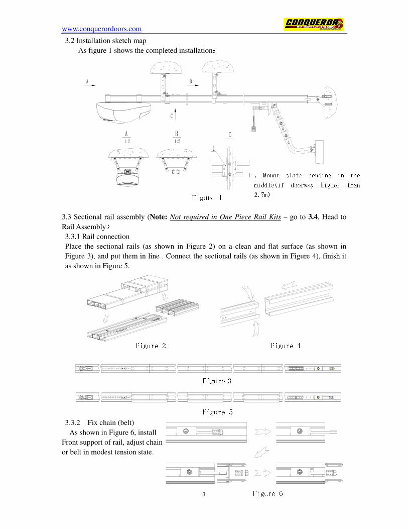
3.2 Installation sketch map
As figure 1 shows the completed installation:
3.3 Sectional rail assembly (Note: Not required in One Piece Rail Kits – go to 3.4, Head to
Rail Assembly)
3.3.1 Rail connection
Place the sectional rails (as shown in Figure 2) on a clean and flat surface (as shown in
Figure 3), and put them in line . Connect the sectional rails (as shown in Figure 4), finish it
as shown in Figure 5.
3.3.2 Fix chain (belt)
As shown in Figure 6, install
Front support of rail, adjust chain
or belt in modest tension state.
1 、 Mount plate bending in the middle(if doorway higher than 2.7m)
Figure 2 Figure 3 Figure 4 Figure 5
Figure 6
Figure 1
www.conquerordoors.com
4
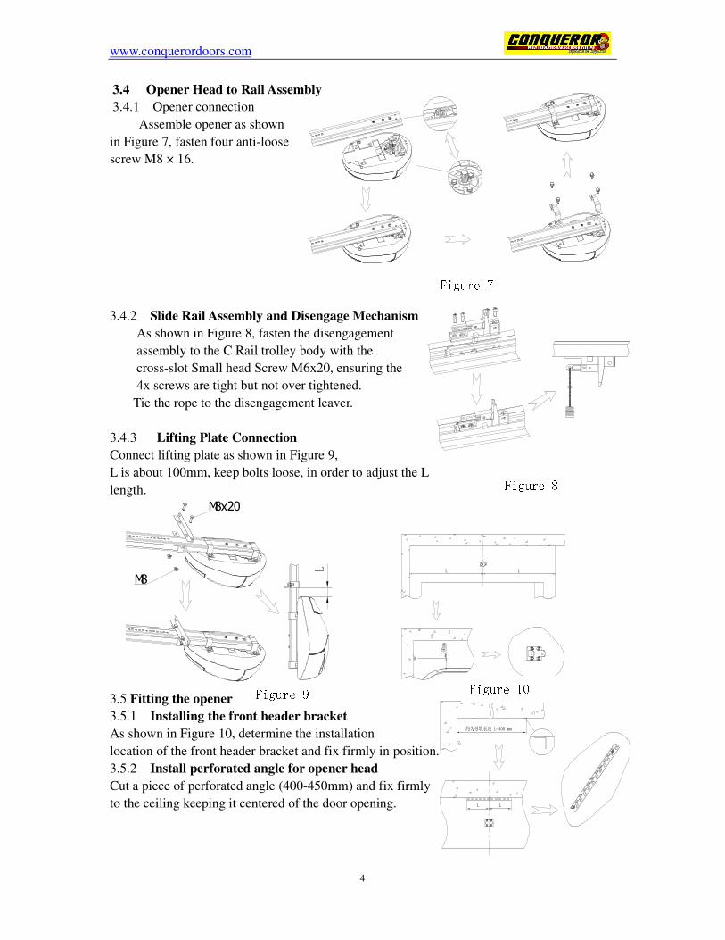
3.4 Opener Head to Rail Assembly
3.4.1 Opener connection
Assemble opener as shown
in Figure 7, fasten four anti-loose
screw M8 × 16.
3.4.2 Slide Rail Assembly and Disengage Mechanism
As shown in Figure 8, fasten the disengagement
assembly to the C Rail trolley body with the
cross-slot Small head Screw M6x20, ensuring the
4x screws are tight but not over tightened.
Tie the rope to the disengagement leaver.
3.4.3 Lifting Plate Connection
Connect lifting plate as shown in Figure 9,
L is about 100mm, keep bolts loose, in order to adjust the L
length.
3.5 Fitting the opener
3.5.1 Installing the front header bracket
As shown in Figure 10, determine the installation
location of the front header bracket and fix firmly in position.
3.5.2 Install perforated angle for opener head
Cut a piece of perforated angle (400-450mm) and fix firmly
to the ceiling keeping it centered of the door opening.
Figure 7
Figure 9 ~
Figure 8 M8x20
M8
Figure 10
www.conquerordoors.com
5
4
3
1
200-300 mm
2
1 2 5 6
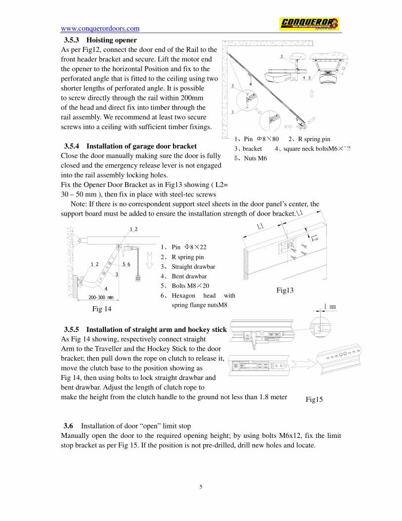
3.5.3 Hoisting opener
As per Fig12, connect the door end of the Rail to the
front header bracket and secure. Lift the motor end
the opener to the horizontal Position and fix to the
perforated angle that is fitted to the ceiling using two
shorter lengths of perforated angle. It is possible
to screw directly through the rail within 200mm
of the head and direct fix into timber through the
rail assembly. We recommend at least two secure
screws into a ceiling with sufficient timber fixings.
3.5.4 Installation of garage door bracket Close the door manually making sure the door is fully
closed and the emergency release lever is not engaged
into the rail assembly locking holes.
Fix the Opener Door Bracket as in Fig13 showing ( L2=
30 – 50 mm ), then fix in place with steel-tec screws
Note: If there is no correspondent support steel sheets in the door panel’s center, the
support board must be added to ensure the installation strength of door bracket.
3.5.5 Installation of straight arm and hockey stick As Fig 14 showing, respectively connect straight
Arm to the Traveller and the Hockey Stick to the door
bracket; then pull down the rope on clutch to release it,
move the clutch base to the position showing as
Fig 14, then using bolts to lock straight drawbar and
bent drawbar. Adjust the length of clutch rope to
make the height from the clutch handle to the ground not less than 1.8 meter
3.6 Installation of door “open” limit stop
Manually open the door to the required opening height; by using bolts M6x12, fix the limit
stop bracket as per Fig 15. If the position is not pre-drilled, drill new holes and locate.
Fig13
1
2
3
54
1、Pin Φ8×80 2、R spring pin
3、bracket 4、square neck boltsM6×12 5、Nuts M6
1、 Pin Φ8×22
2、 R spring pin
3、 Straight drawbar
4、 Bent drawbar
5、 Bolts M8×20
6、 Hexagon head with
spring flange nutsM8
Fig15
Fig 14
www.conquerordoors.com
6
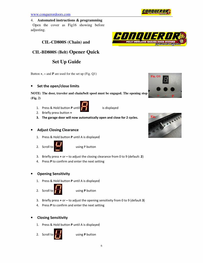
4. Automated instructions & programming
Open the cover as Fig16 showing before
adjusting.
CIL-CD800S (Chain) and
CIL-BD800S (Belt) Opener Quick
Set Up Guide
Button +, – and P are used for the set up (Fig. Q1)
• Set the open/close limits
NOTE: The door, traveler and chain/belt spool must be engaged. The opening stop must be installed
(Fig. 2)
1. Press & Hold button P until is displayed
2. Briefly press button +
3. The garage door will now automatically open and close for 2 cycles.
• Adjust Closing Clearance
1. Press & Hold button P until A is displayed
2. Scroll to using P button
3. Briefly press + or – to adjust the closing clearance from 0 to 9 (default: 2)
4. Press P to confirm and enter the next setting
• Opening Sensitivity
1. Press & Hold button P until A is displayed
2. Scroll to using P button
3. Briefly press + or – to adjust the opening sensitivity from 0 to 9 (default 3)
4. Press P to confirm and enter the next setting
• Closing Sensitivity
1. Press & Hold button P until A is displayed
2. Scroll to using P button
Fig. Q1
Fig.
+ - P
www.conquerordoors.com
7
3. Briefly press + or – to adjust the closing sensitivity from 0 to 9 (default 3)
4. Press P to confirm and enter the next setting
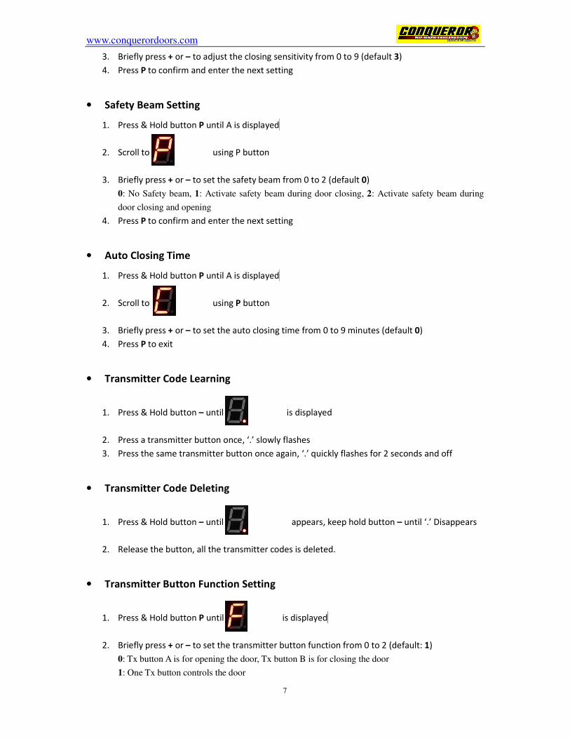
• Safety Beam Setting
1. Press & Hold button P until A is displayed
2. Scroll to using P button
3. Briefly press + or – to set the safety beam from 0 to 2 (default 0)
0: No Safety beam, 1: Activate safety beam during door closing, 2: Activate safety beam during
door closing and opening
4. Press P to confirm and enter the next setting
• Auto Closing Time
1. Press & Hold button P until A is displayed
2. Scroll to using P button
3. Briefly press + or – to set the auto closing time from 0 to 9 minutes (default 0)
4. Press P to exit
• Transmitter Code Learning
1. Press & Hold button – until is displayed
2. Press a transmitter button once, ‘.’ slowly flashes
3. Press the same transmitter button once again, ‘.’ quickly flashes for 2 seconds and off
• Transmitter Code Deleting
1. Press & Hold button – until appears, keep hold button – until ‘.’ Disappears
2. Release the button, all the transmitter codes is deleted.
• Transmitter Button Function Setting
1. Press & Hold button P until is displayed
2. Briefly press + or – to set the transmitter button function from 0 to 2 (default: 1)
0: Tx button A is for opening the door, Tx button B is for closing the door
1: One Tx button controls the door
www.conquerordoors.com
8 150mm
2: Tx button A controls the door, Tx button B controls the light
3. Press P to confirm and enter the next setting
• Auto Closing with/without Safety Beam
1. Press & Hold button P until F is displayed
2. Scroll to using P button
3. Briefly press + or – to set the auto closing from 0 to 1 (default 1)
0: Auto closing without safety beam, 1: Auto closing with safety beam
4. Press P to confirm and enter the next setting
• Reset To Factory Default
1. Press & Hold button P until F is displayed
2. Scroll to using P button
3. Briefly press + or – to select from 0 to 2 (default 0)
0: No reset, 1: Reset to factory default setting and keep transmitter codes, 2: Reset to factory
default setting and delete all the transmitter codes
4. Press P to confirm and exit 4.4 Fault information
This opener could auto detect the error during running, and display the error information.
When error occurs, digital tube could display the error code, the radix point will also flash
quickly. After 5 seconds of flash of error information, it will automatically recover to display
normally.
a) “1.”: means the journey setting fault.
b) “2.”: means protection against obstacle during opening
c) “3.”: means protection against obstacle during closing.
d) “4.”: means opto-beam shielded/blocked or photocell is damaged.
e) “5.”: means transmitter error in learning or coding.
f) “6.”: means the running time exceeded 100 seconds.
g) “7.” :means speed sensor is damaged;
h) “8.” :means DC motor is damaged.
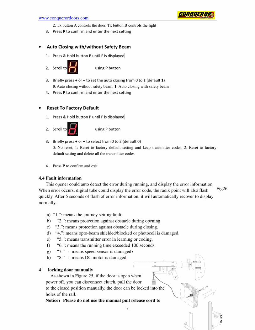
4 locking door manually
As shown in Figure 25, if the door is open when
power off, you can disconnect clutch, pull the door
to the closed position manually, the door can be locked into the
holes of the rail.
Notice::::Please do not use the manual pull release cord to
Fig26
www.conquerordoors.com
9
SW-WALL
PHOTO
AL-IN
AL-SPK
XT4
SW-WALL
PHOTO
AL-IN
AL-SPK
XT4
SW-WALL
PHOTO
AL-IN
AL-SPK
XT4
RED
BLACK
- BATTERY +
XT6
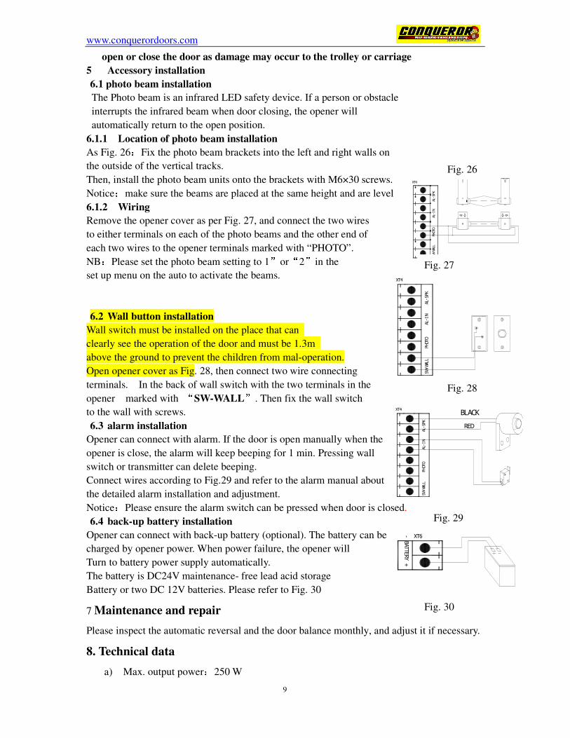
open or close the door as damage may occur to the trolley or carriage
5 Accessory installation
6.1 photo beam installation
The Photo beam is an infrared LED safety device. If a person or obstacle
interrupts the infrared beam when door closing, the opener will
automatically return to the open position.
6.1.1 Location of photo beam installation
As Fig. 26:Fix the photo beam brackets into the left and right walls on
the outside of the vertical tracks.
Then, install the photo beam units onto the brackets with M6×30 screws.
Notice:make sure the beams are placed at the same height and are level
6.1.2 Wiring
Remove the opener cover as per Fig. 27, and connect the two wires
to either terminals on each of the photo beams and the other end of
each two wires to the opener terminals marked with “PHOTO”.
NB:Please set the photo beam setting to 1”or“2”in the
set up menu on the auto to activate the beams.
6.2 Wall button installation
Wall switch must be installed on the place that can
clearly see the operation of the door and must be 1.3m
above the ground to prevent the children from mal-operation.
Open opener cover as Fig. 28, then connect two wire connecting
terminals. In the back of wall switch with the two terminals in the
opener marked with “SW-WALL”. Then fix the wall switch
to the wall with screws.
6.3 alarm installation
Opener can connect with alarm. If the door is open manually when the
opener is close, the alarm will keep beeping for 1 min. Pressing wall
switch or transmitter can delete beeping.
Connect wires according to Fig.29 and refer to the alarm manual about
the detailed alarm installation and adjustment.
Notice:Please ensure the alarm switch can be pressed when door is closed.
6.4 back-up battery installation
Opener can connect with back-up battery (optional). The battery can be
charged by opener power. When power failure, the opener will
Turn to battery power supply automatically.
The battery is DC24V maintenance- free lead acid storage
Battery or two DC 12V batteries. Please refer to Fig. 30
7 Maintenance and repair
Please inspect the automatic reversal and the door balance monthly, and adjust it if necessary.
8. Technical data
a) Max. output power:250 W
Fig. 26
Fig. 27
Fig. 28
Fig. 29
Fig. 30

www.conquerordoors.com
10
b) Max. lifting force:800 N
c) Opening and closing speed:160 mm/s
d) light:12 V(high light LED)
e) motor:DC 24 V
f) Remote control distance:≥30 m
g) Remote frequency:433.92 MHz
h) Transmitter amount:100 pcs
i) Temperature:-25� ~ +55 �
j) Back-up battery:DC24V 4-7Ah maintenance- free lead acid storage battery
www.conquerordoors.com
11
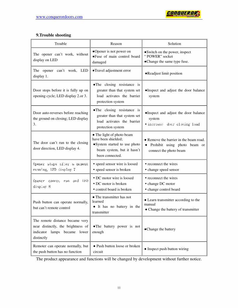
9.Trouble shooting
The product appearance and functions will be changed by development without further notice.
Trouble Reason Solution The opener can’t work, without
display on LED
●Opener is not power on
●Fuse of main control board
damaged
●Switch on the power, inspect
“ POWER” socket
●Change the same type fuse.
The opener can’t work, LED
display 1. ●Travel adjustment error
●Readjust limit position
Door stops before it is fully up on
opening cycle; LED display 2.or 3.
●The closing resistance is
greater than that system set
load activates the barrier
protection system
●Inspect and adjust the door balance
system
Door auto-reverses before reaching
the ground on closing; LED display
3. ●The closing resistance is
greater than that system set
load activates the barrier
protection system
●Inspect and adjust the door balance
system
� increase door closing load
The door can’t run to the closing
door direction, LED display 4. ● The light of photo beam
have been shielded;
●System started to use photo
beam system, but it hasn’t
been connected.
● Remove the barrier in the beam road.
● Prohibit using photo beam or
connect the photo beam Opener stops after a moment running, LED display 7 � speed sensor wire is loosed
� speed sensor is broken
� reconnect the wires
� change speed sensor Opener cannot run and LED display 8 � DC motor wire is loosed
� DC motor is broken
� control board is broken
� reconnect the wires
� change DC motor
� change control board
Push button can operate normally,
but can’t remote control
● The transmitter has not
learned
● It has no battery in the
transmitter
● Learn transmitter according to the
manual
● Change the battery of transmitter
The remote distance became very
near distinctly, the brightness of
indicator lamps became lower
distinctly
●The battery power is not
enough ●Change the battery
Remoter can operate normally, but
the push button has no function ● Push button loose or broken
circuit ● Inspect push button wiring