Embed Size (px)
Citation preview

WESTERN MUNICIPAL WATER DISTRICT Submittals LAKE HILLS 1860 BPS GENERATOR 01300-1 August 2017
SECTION 01300
SUBMITTALS
PART 1 – GENERAL
1.01 DESCRIPTION OF REQUIREMENTS
A. This Section includes provisions for Contractor submittals. Additional provisions
may be included in specific Specifications Sections.
B. This Section contains general information pertaining to the processing of
submittals. Additional detailed submittal requirements are contained within the
individual technical Specifications Sections.
C. Number of Copies Required
1. Each Submittal: The Contractor shall furnish a minimum of eight (8) copies
of each submittal unless specified otherwise. Four (4) copies will be
delivered to WMWD and four (4) copies will be delivered to Linkture at the
addresses listed below. WMWD will return three (3) copies of each
submittal to the Contractor with comments noted thereon. In lieu of hard
copies electronic PDF copies may be submitted during the review process
but final submittal shall be hard copies. Five (5) hard copies shall be
submitted for the final submittal. Contractor shall keep one (1) of the final
submittal at the job site at all times.
D. Delivery Addresses:
1. Submittals shall be mailed with the appropriate number of copies as
follows:
Wester Municipal Water District
14205 Meridian Parkway
Riverside, CA 92518
Attn: Jimmy Chen, P.E., Senior Civil Engineer
Jimmy Chen [[email protected]]
Linkture Corp.
6240 W Third Street, Suite 421
Los Angeles, CA 90036
Attn: Opty Fernandez
Opty Fernandez [[email protected]]
E. This Section specifies the general methods and requirements of submissions
applicable to the following work-related submittals: Shop Drawings, Product Data,

WESTERN MUNICIPAL WATER DISTRICT Submittals LAKE HILLS 1860 BPS GENERATOR 01300-2 August 2017
Manuals, Samples, Certificates of Compliance, Statements of Qualifications, Test
Results, Survey Data, Calculation's and Construction or Submittal Schedules.
Detailed submittal requirements will be specified in the technical Specifications
sections.
F. All submittals shall be clearly identified by reference to Specification Section,
Paragraph and Drawing No. or Detail as applicable. Submittals shall be clear and
legible and of sufficient size for sufficient presentation of data. The "Submittal
Transmittal Form" and the "Certification Statement" to be used with each submittal
is included at the end of this Section.
G. Prepare, maintain, and submit submittal logs as specified herein.
1.02 SHOP DRAWINGS, PRODUCT DATA AND SAMPLES
A. Shop Drawings
1. Shop drawings include, but are not necessarily limited to, custom-prepared
data such as fabrication and erection/installation (working) drawings,
design calculations, lists, graphs, operating instructions, scheduled
information, setting diagrams, actual shop work manufacturing instructions,
custom templates, special wiring diagrams, coordination drawings,
individual system or equipment inspection and test reports including
performance curves and certifications, as applicable to the work.
2. All details on shop drawings submitted for approval shall show clearly the
relation of the various parts of the work and control lines, and where correct
fabrication of the work depends upon field measurements such
measurements shall be made and noted on the drawings before being
submitted for approval.
3. Submittals for equipment specified under Divisions 1, 2, 13, 15 and 16 shall
include a listing of all installations where identical or similar equipment has
been installed and been in operation for a period of at least five years unless
otherwise indicated as longer in these Specifications.
B. Product Data
1. Product data as specified in individual Sections include, but are not
necessarily limited to, standard prepared data for manufactured products
(sometimes referred to as catalog data), such as the manufacturer's product
specification and installation instructions, availability of colors and
patterns, manufacturer's printed statements of compliance and applicability,
roughing-in diagrams and templates, catalog cuts, product photographs,
standard wiring diagrams, printed performance curves and operational-
range diagrams, production or quality control inspection and test reports and
certifications, mill reports, product operating and maintenance instructions

WESTERN MUNICIPAL WATER DISTRICT Submittals LAKE HILLS 1860 BPS GENERATOR 01300-3 August 2017
and recommended spare-parts listing and printed product warranties, as
applicable to the work.
C. Samples
1. Samples specified in individual Sections include, but are not necessarily
limited to, physical examples of the work, such as sections of manufactured
or fabricated work, small cuts or containers of materials, complete units of
repetitively-used products, color/texture/pattern swatches and range sets,
specimens for coordination of visual effect, graphic symbols and units of
work to be used by the District for independent inspection and testing, as
applicable to the work.
1.03 CONTRACTOR'S RESPONSIBILITIES
A. The CONTRACTOR shall prepare, approve, sign and submit to the Engineer any
and all Shop Drawings, Manufacturers' Project Data, Job References, Certificates,
Wiring Diagrams, Operation and Maintenance Manuals and Samples required by
the Contract Documents.
NOTE: All references in the Technical Sections under "Shop Drawings" or
“Submittal” to the words "approval of" shall mean "reviewed by".
B. The CONTRACTOR, by preparing, reviewing, approving and submitting the Shop
Drawings, Manufacturers' Product Data, Job References, Certifications, Wiring
Diagrams, Operation and Maintenance Manuals and Samples, represents that the
CONTRACTOR has determined and verified all materials, field measurements and
filed construction criteria related thereto, and has checked and coordinated the
information contained within such submittals with the requirements of the Work,
the Project and the Contract Documents.
C. The CONTRACTOR shall inform the Engineer, in writing, of any and all
deviations and/or questions regarding the Contract Documents, and shall properly
identify these areas of concern in the letter of transmittal of the Shop Drawings,
Manufacturers' Product Data, Job References, Certification, Wiring Diagram and
Samples for proper written disposition respectively by the Engineer. The
CONTRACTOR shall provide reproducible Shop Drawings which exceed 11-inch
x 17-inches and number of copies as described elsewhere.
D. All Shop Drawings, Manufacturers' Product Data, Wiring Diagrams, Job
References, Certifications, Operation and Maintenance Manuals and Samples
submitted, shall be accompanied by a preprinted standard transmittal form with
submittal number, and shall be addressed to the Engineer to be received and filed.
E. The Contractor is not relieved of the responsibility for any deviation from the
requirements of the Contract Documents, by virtue of Contractor’s approval and
submittal of the Shop Drawings, Manufacturers' Product Data, Wiring Diagrams,
Operation and Maintenance Manuals and Samples to the Engineer. All deviations

WESTERN MUNICIPAL WATER DISTRICT Submittals LAKE HILLS 1860 BPS GENERATOR 01300-4 August 2017
and/or interpretations of the Contract Documents must be approved in writing by
the Engineer.
F. The review of the Shop Drawings, Manufacturers' Product Data, Job References,
Certifications, Wiring Diagrams, Operation and Maintenance Manuals; and
Samples by the Engineer does not relieve the Contractor of its responsibility from
any requirements of the Contract Document, or any errors or omissions in such
submittals, or for any failure to perform the requirements and intent of Contract
Documents. The Contractor shall be responsible for a fully functional system as
intended by the Contract Documents.
G. The Contractor shall review shop drawings, product data and samples, including
those by subcontractors, prior to submission to determine and verify the following:
1. Catalog numbers and similar data.
2. Conformance with the Specifications.
E. Each shop drawing, sample and product data submitted by the Contractor shall have
affixed to it the following Certification Statement including the Contractor's
Company name and signed by the Contractor: "Certification Statement: By this
submittal, I hereby represent that I have determined and verified all materials,
dimensions, catalog numbers and similar data, and I have checked and coordinated
each item with other applicable approved shop drawings and all Contract
requirements." Shop drawings and product data sheets 11 inches x 17 inches and
smaller shall be bound together in an orderly fashion and bear the above
Certification Statement on the cover sheet. The cover sheet shall fully describe the
packaged data and include a listing of all items within the package. Provide to the
Engineer a copy of each submittal transmittal sheet for shop drawings, product data
and samples at the time of submittal of said drawings, product data and samples to
the Engineer.
F. The Contractor shall utilize a 10-character submittal identification numbering
system in the following manner:
1. The first two characters shall be SD, SL, OM, CC, SQ or TR which
represents Shop/Working Drawing and other Product Data (SD), Sample
(SL), Operating/Maintenance Manual (OM), Certificate of Compliance
(CC), Statement of Qualification (SQ), or Test Results/Report (TR).
2. The next two digits shall be the numbers 01-99 to sequentially number each
initial separate item or drawing submitted.
3. The next character shall be a letter, A-Z, indicating the submission, or
resubmission of the same Drawing, i.e., A=1st submission, B=2nd
submission, C=3rd submission, etc.
4. The next five digits shall be the applicable Specifications Section Number.

WESTERN MUNICIPAL WATER DISTRICT Submittals LAKE HILLS 1860 BPS GENERATOR 01300-5 August 2017
A typical submittal number would be as follows: SD-08-B-13122
SD = Shop Drawing
08 = The eighth initial submittal
B = The second submission (first resubmission) of that
particular shop drawing
13122 = Specifications Section
G. Notify the Engineer in writing, at the time of submittal, of any deviations in the
submittals from the requirements of the Contract Documents.
H. The review and approval of shop drawings, samples or product data by the Engineer
shall not relieve the Contractor from his/her responsibility with regard to the
fulfillment of the terms of the Contract. All risks of error and omission are assumed
by the Contractor and the Owner and Engineer will have no responsibility thereof.
I. No portion of the Work requiring a shop drawing, sample, or product data shall be
started nor shall any materials be fabricated or installed prior to the approval or
qualified approval of such item. Fabrication performed, materials purchased or on-
site construction accomplished which does not conform to approved shop drawings
and data shall be at the Contractor's risk. The Owner will not be liable for any
expense or delay due to corrections or remedies required to accomplish conformity.
J. Project Work, materials, fabrication, and installation shall conform to approved
shop drawings, applicable samples, and product data.
1.02 SUBMISSION REQUIREMENTS
D. Make submittals promptly in accordance with approved schedule, and in such
sequence as to cause no delay in the Work or in the work of any other contractor.
E. Each submittal, appropriately coded, will be returned within thirty (30) Calendar
Days following receipt of submittal by the Engineer.
F. Number of submittals required:
G. Shop Drawings: Eight (8) copies.
H. Product Data: Eight (8) copies.
I. Samples: Submit the number stated in the respective Specification Sections. D.
Submittals shall contain:
1. Submittal identification number
2. The date of submission and the dates of any previous submissions.

WESTERN MUNICIPAL WATER DISTRICT Submittals LAKE HILLS 1860 BPS GENERATOR 01300-6 August 2017
3. The Project title and number.
4. Contractor identification.
5. The names and telephone numbers of:
a. Contractor
b. Supplier
c. Manufacturer
6. Field dimensions, clearly identified as such.
7. Identification of deviations from Contract Documents.
8. Identification of revisions on resubmittals.
1.03 REVIEW OF SHOP DRAWINGS, PRODUCT DATA, WORKING DRAWINGS AND
SAMPLES
D. The review of shop drawings, data, and samples will be for general conformance
with the design concept and Contract Documents. They shall not be construed:
1. as permitting any departure from the Contract requirements;
2. as relieving the Contractor of responsibility for any errors, including details,
dimensions, and materials;
3. as approving departures from details furnished by the Owner, except as
otherwise provided herein.
E. The Contractor remains responsible for details and accuracy, for coordinating the
Work with all other associated work and trades, for selecting fabrication processes,
for techniques of assembly, and for performing work in a safe manner.
F. If the shop drawings, data or samples as submitted describe variations and show a
departure from the Contract requirements which Engineer finds to be in the interest
of the Owner and to be so minor as not to involve a change in Contract Price or
time for performance, the Engineer may return the reviewed drawings without
noting an exception.
G. WMWD will reject incomplete submittals as not complying with the Contract
requirements. Contractor shall provide space for 2.5” by 3.5” review stamp for each
submittal.
H. After receipt of a complete submittal and within the time limits described below,
the Engineer will transmit the submittal back to the Contractor marked with one of
the following review status:
WESTERN MUNICIPAL WATER DISTRICT Submittals LAKE HILLS 1860 BPS GENERATOR 01300-7 August 2017
“Reviewed, No Exceptions Taken”
“Make Corrections Noted, Do Not Resubmit”
“Revised and Resubmit”
“Rejected”
I. For items marked “Make Corrections Noted, Do Not Resubmit,” the revisions will
be marked on the submittal or will be described as comments in the response letter.
The submittal will be considered approved without formal revision. The
CONTRACTOR shall, within 7 calendar days, submit two (2) corrected record
copies of the submittal to the District Engineer for record purposes.
J. If the submittal is returned to the Contractor marked “Revised and Resubmit,” the
submittal will be transmitted to the Contractor with a statement of the deficiencies.
The Contractor shall promptly revise the submittal and resubmit eight (8) copies to
the Engineer.
K. If the submittal is returned to the Contractor marked “Rejected,” the Contractor
shall revise said submittal and shall resubmit eight (8) copies of said revised
submittal to the Engineer.
L. Revisions indicated on submittals shall be considered as changes necessary to meet
the requirements of the Contract Documents, Specifications, or Drawings.
Submittal revisions shall not be taken as the basis of claims for extra work. The
Contractor shall have no claim for damages or extension of time due to any delay
resulting from making required revisions to the submittals. The review of
submittals by WMWD shall in no way relieve the Contractor of responsibility for
errors or omissions contained therein nor will such review operate to waive or
modify any provisions or requirements contained in the Contract Documents,
Specifications, or Drawings.
M. After approval of submittals, the Contractor shall not deviate from the approved
submittal without the prior written consent from the District Engineer.
Commencement of production Work performed in advance of the receipt of
approval of submittals shall be entirely at the Contractor’s risk.
N. Resubmittals will be handled in the same manner as first submittals. On
resubmittals the Contractor shall direct specific attention, in writing on the letter of
transmittal and on resubmitted shop drawings by use of revision triangles or other
similar methods, to revisions other than the corrections requested by the Engineer,
on previous submissions. Any such revisions which are not clearly identified shall
be made at the risk of the Contractor. The Contractor shall make corrections to any
work done because of this type revision that is not in accordance to the Contract
Documents as may be required by the Engineer.

WESTERN MUNICIPAL WATER DISTRICT Submittals LAKE HILLS 1860 BPS GENERATOR 01300-8 August 2017
Partial submittals may not be reviewed. The Engineer will be the only judge as to
the completeness of a submittal. Submittals not complete will be returned
to the Contractor, and will be considered “Rejected” until resubmitted. The
Engineer may at his/her option, provide a list or mark the submittal directing
the Contractor to the areas that are incomplete.
O. Repetitive Review
1. Shop drawings and other submittals will be reviewed no more than twice at
the Engineer's expense. All subsequent reviews will be performed at times
convenient to the Engineer and at the Contractor's expense, based on the
Engineer's then prevailing rates. The Contractor shall reimburse the Owner
for all such fees invoiced to the Owner. Submittals are required until
approved.
2. Any need for more than one resubmission, or any other delay in obtaining
Engineer's review of submittals, will not entitle Contractor to extension of
the time for completion.
P. If the Contractor considers any correction indicated on the shop drawings to
constitute a change to the Contract Documents, the Contractor shall give written
notice thereof to the Owner and Engineer at least seven work days prior to release
for manufacture.
Q. When the shop drawings have been completed to the satisfaction of the Engineer,
the Contractor shall carry out the construction in accordance therewith and shall
make no further changes therein except upon written instructions from the Owner
or Engineer.
1.04 DISTRIBUTION
D. Distribute reproductions of approved shop drawings and copies of approved
product data and samples, where required, to the job site file and elsewhere as
directed by the Owner. Number of copies shall be as directed by the Owner but
shall not exceed eight.
1.05 SCHEDULES
D. Provide all schedules required by the requirements of these Specifications.
1.06 PROFESSIONAL ENGINEER (P.E.) CERTIFICATION FORM
D. If specifically required in other Sections of these Specifications, the Contractor
shall submit a P.E. Certification for each item required on the form which follows
in this Section, completely filled in and stamped.
1.07 GENERAL PROCEDURES FOR SUBMITTALS

WESTERN MUNICIPAL WATER DISTRICT Submittals LAKE HILLS 1860 BPS GENERATOR 01300-9 August 2017
D. Coordination of Submittal Times: Prepare and transmit each submittal sufficiently
in advance of performing the related work or other applicable activities, or within
the time specified in the individual sections of the Specifications so that the
installation will not be delayed by processing times including disapproval and
resubmittal (if required), coordination with other submittals, testing, purchasing,
fabrication, delivery and similar sequenced activities. No extension of the time for
completion will be authorized because of the Contractor's failure to transmit
submittals sufficiently in advance of the work.
1.08 QUALITY CONTROL SUBMITTALS
D. Certificates:
1. Manufacturer's Certificate of Compliance:
a. When specified in individual Specification sections or where
products are specified to a recognized standard or code, submit prior
to shipment of product or material to the Project site.
b. Engineer may permit use of certain materials or assemblies prior to
sampling and testing if accompanied by accepted certification of
compliance.
c. Signed by product manufacturer certifying that materials,
manufacture, and product specified conform to or exceed specified
requirements and intent for which product will be used. Submit
supporting reference data, affidavits, and certifications as
appropriate.
d. May reflect recent or previous test results on material or product,
but must be acceptable to Engineer.
2. Certificates of Successful Testing or Inspection: Submit when testing or
inspection is required by Laws and Regulations or governing agency or
specified in the individual Specification sections.
E. Operation and Maintenance Manual: Submit Operation and Maintenance Manual
in accordance with Section 01430, Operation and Maintenance Data.
F. Statements of Qualification: Evidence of qualification, certification, or registration.
As required in these Contract Documents to verify qualifications of Engineers,
materials testing laboratories, specialty Subcontractors, trades, specialists,
consultants, installers, and other professionals.
G. Written Test Reports of Each Test and Inspection: As a minimum, include the
following:

WESTERN MUNICIPAL WATER DISTRICT Submittals LAKE HILLS 1860 BPS GENERATOR 01300-10 August 2017
1. Date of test and date issued, Project title and number, testing laboratory
name, address, and telephone number, and name and signature of laboratory
inspector.
2. Date and time of sampling or inspection and record of temperature and
weather conditions.
3. Identification of product and Specification section, location of Sample, test
or inspection in the Project, type of inspection or test with referenced
standard or code, certified results of test.
4. Compliance with Contract Documents, and identifying corrective action
necessary to bring materials and equipment into compliance.
5. Provide an interpretation of test results, when requested by Engineer.
1.09 SUBMITTAL LOG
D. The Contractor shall prepare and maintain an accurate submittal log for the duration
of the project. The Contractor shall submit six copies of the initial submittal log
within 30 Calendar Days after Notice to Proceed. The Contractor shall submit six
copies of the updated submittal log once a month and upon request of the Engineer
or the District. The submittal log shall contain a listing of all submittals required by
the Contract Documents and shall include the following.
1. Submittal identification number
2. Specification Section Reference
3. Description of submittal item
4. Projected submission date
5. Actual submission date
6. Date returned by the Engineer
7. Notation of the Engineer's response
8. Notation if re-submittal or record copy is required
PART 2 - PRODUCTS (NOTUSED)
PART3 - EXECUTION (NOTUSED)

WESTERN MUNICIPAL WATER DISTRICT Submittals LAKE HILLS 1860 BPS GENERATOR 01300-11 August 2017
P. E. CERTIFICATION FORM
The undersigned hereby certifies that he/she is a Professional Engineer registered in the State of
California and that he/she has been employed by _________________________________
(Name of Contractor) to design: _________________________________________________
located in __________________________________________________________________, in
accordance with Specifications Section __________________ for the Lake Hills 1860 Booster
Station Emergency Generator Replacement Project. The undersigned further certifies that he/she
has performed the design of the
_________________________________________________________________________
____________________________________________________________________________
______________________________________________________________________________
______________________________________________________________________________
______________________________________________________________________________
______________________________________________________________________________
______________________________________________________________________________
__________________________________________________________________
that said design is in conformance with all applicable local, state and federal codes, rules, and
regulations, and that his/her signature and P.E. stamp have been affixed to all calculations and
drawings used in, and resulting from, the design.
The undersigned hereby agrees to make all original design drawings and calculations available to
the Western Municipal Water District (District), whose address is 14205 Meridian Parkway
Riverside, CA 92518 or the District's representative within seven (7) days following written
request thereof by the District.
__________________________________ ___________________________________
P.E. Name (Printed) & Title Contractor's Name (Printed) & Title
__________________________________ ___________________________________
P.E.'s Signature Contractor's Signature
__________________________________ ___________________________________
Address Address

WESTERN MUNICIPAL WATER DISTRICT Submittals LAKE HILLS 1860 BPS GENERATOR 01300-12 August 2017
Submittal Transmittal/Certification Form
Project Name: Lake Hills 1860 Pressure Zone Booster Station Generator Replacement
To: Linkture Corp.
6260 W Third Street, Suite 437
Los Angeles, California 90036
Attn: Opty Fernandez
From: _____________________________
_____________________________
_____________________________
_____________________________
Description:
____________________________________________________________________
______________________________________________________________________________
Submittal #: __________ - ____________ - __________ - ________________
Type Submittal # Submission Section
Date: _________________ Date of Previous Submission: ________________ Copies:_______
Supplier: ____________________________________ Phone No:
_________________________
Manufacturer: ________________________________Phone No:
__________________________
Additional Attachments
� PE Certificate Required � Identification of Deviations from Contract Docs
� Identification of Revisions � Certification Attached
� Field Dimensions Clearly Identified � Other
_______________________________
Remarks: ___________________________________________________________________
____________________________________________________________________________
____________________________________________________________________________
____________________________________________________________________________
____________________________________________________________________________
Relationship to Critical Features of Work:
__________________________________________

WESTERN MUNICIPAL WATER DISTRICT Submittals LAKE HILLS 1860 BPS GENERATOR 01300-13 August 2017
Certification Statement: By this submittal, I hereby represent that I have determined and verified
all materials, dimensions, catalog numbers and similar data, and I have checked and coordinated
each item with other applicable approved shop drawings and all Contract requirements.
By: ___________________________________ _____________________
Signature Date

WESTERN MUNICIPAL WATER DISTRICT Submittals LAKE HILLS 1860 BPS GENERATOR 01300-14 August 2017
END OF SECTION

WESTERN MUNICIPAL WATER DISTRICT PRODUCT SHIPMENT, HANDLING, STORAGE LAKE HILLS 1860 BPS GENERATOR AND PROTECTION August 2017 01600-1
SECTION 01600
PRODUCT SHIPMENT, HANDLING, STORAGE AND PROTECTION
PART 1 – GENERAL
1.01 SCOPE OF WORK
A. Furnish all labor, materials and incidentals required to provide shipment, handling,
storage, and protection of material and equipment products.
1.02 SUBMITTALS
A. Supplier shall submit the following:
1. Assembly instructions for parts shipped unassembled.
2. Manufacturer's instructions for unloading, handling, storage, maintenance,
and protection prior to installation, with each shipment of each product type.
3. Manufacturer's instructions for maintenance of products.
1.03 PREPARATION FOR SHIPMENT
A. When practical, factory assemble products. Match mark or tag separate parts and
assemblies to facilitate field assembly. Cover machined and unpainted parts that
maybe damaged by the elements with a strippable protective coating. Label each
package requiring space heater connection during storage. Furnish instructions for
connection of space heaters on motors during storage.
B. Package materials and equipment to facilitate handling and protect from damage
during shipping, handling and storage. Mark or tag outside of each package or crate
to indicate its purchase order number, bill of lading number, contents by name,
name of Project and Contractor, equipment number, and approximate weight.
Include complete packing lists and bills of materials with each shipment.
C. Spare Parts, Special Tools, and Maintenance Materials:
1. Furnish as required by the Specifications prior to operation of the equipment
by the District.
2. Properly package to avoid damage, in original cartons insofar as possible.
Replace parts damaged or otherwise inoperable.
3. Firmly affix to and prominently display on each package.

WESTERN MUNICIPAL WATER DISTRICT PRODUCT SHIPMENT, HANDLING, STORAGE LAKE HILLS 1860 BPS GENERATOR AND PROTECTION August 21, 2017 01600-2
a. Minimum 3- by 6-inch manila shipping tag with the following
information printed clearly with permanent ink:
(1) Manufacturer's part description and number.
(2) Applicable equipment description.
(3) Quantity of parts in package.
(4) Equipment manufacturer.
(5) Applicable Specifications section.
(6) Name of Contractor
(7) Owner and Project names as shown below. Owner: Western
Municipal Water District. Project: Lake Hills 1860 Pressure
Zone Booster Station Emergency Generator Replacement.
4. Deliver materials to the Lake Hills 1860 Booster Station site.
D. Factory Test Results: Reviewed and accepted by Engineer before product shipment
as required in individual Specifications sections.
1.04 DELIVERY
A. Deliver products in undamaged condition, in manufacturer's original container or
packaging, and with identifying labels intact and legible. Include on label date of
manufacture and shelf life, where applicable. Include UL labels on products so
specified.
1.05 RECEIVING AND INSPECTION
A. Upon receipt of products at the jobsite, Contractor shall inspect for completeness
and evidence of damage during shipment.
1. Expedite replacement of damaged, incomplete, or lost items.
1.06 HANDLING, STORAGE AND PROTECTION
A. Handling, unloading, storage and protecting materials and equipment shall be in
accordance with manufacturers' written recommendations and shall be performed
so as to avoid any damage.
B. Any damaged materials, equipment or parts shall be replaced to the satisfaction of
the Owner.
C. Provide power to space heaters to keep condensation within electrical equipment.

WESTERN MUNICIPAL WATER DISTRICT PRODUCT SHIPMENT, HANDLING, STORAGE LAKE HILLS 1860 BPS GENERATOR AND PROTECTION August 2017 01600-3
END OF SECTION

WESTERN MUNICIPAL WATER DISTRICT Manufacturer’s Field Services LAKE HILLS 1860 BPS GENERATOR 01640-1 August 2017
SECTION 01640
MANUFACTURER'S FIELD SERVICES
PART 1 - GENERAL
1.01 WORK INCLUDED
A. Manufacturer's field services shall be provided for equipment where specified in
individual Specifications sections and where deemed necessary to complete the
work. Scheduling of these services must be performed by the Contractor and
coordinated with the District and manufacturer's representative(s).
1.02 SUBMITTALS
A. Training Schedule and Materials
1. Submit written outlines of proposed training sessions during shop drawing
submittal phase and revise as necessary for acceptance.
2. Provide complete training materials to include operation and maintenance
data as required in this Section.
3. Submit training schedule for District approval.
B. Quality Control Submittals:
C. Certificate of qualification of manufacturer's representative during shop drawing
submittal phase.
D. Manufacturer's Certificate of Proper Installation.
E. Report of Successful Testing and Start-up.
1.03 QUALIFICATION OF MANUFACTURER'S REPRESENTATIVE
A. Authorized representative of the manufacturer, factory trained, and experienced in
the technical applications, installation, operation, and maintenance of respective
equipment, subsystem, or system. Representative subject to acceptance by the
District. No substitute representatives will be allowed unless prior written approval
by the District has been given.
1.04 EQUIPMENT AND SYSTEMS
A. Equipment furnished under other Divisions shall include the cost of competent
representative of the manufacturers of all equipment to supervise the installation,
WESTERN MUNICIPAL WATER DISTRICT Manufacturer’s Field Services LAKE HILLS 1860 BPS GENERATOR 01640-2 August 2017
adjustment and testing of the equipment and to instruct the Owner's operating
personnel on operation and maintenance where specified herein.
B. Equipment requiring manufacturer's field services during installation, start-up,
testing, and training/instruction are as following, but not limited to: Equipment
Installation Start-up Testing Training for the Generator, Manual Transfer Switch,
and Load Bank.
1.05 FULFILLMENT OF SPECIFIED MINIMUM SERVICES
A. Where manufacturer's services are specified, furnish manufacturer's
representative qualified to provide these services.
B. Schedule manufacturer's field services to avoid conflicting with other field testing
or other manufacturer's field services unless they are from related or
connecting components.
C. Manufacturer's services shall include as a minimum:
1. Coordinating with Contractor and District as required to schedule each field
service to be provided under these Specifications.
2. Assistance during installation to include observation, guidance, instruction
of Contractor's assembly, erection, installation or application procedures
3. Inspection, checking, and adjustment as required for equipment to function
as warranted by manufacturer and necessary to provide written approval of
installation.
4. Revisiting the site as required to correct problems and until installation and
operation are acceptable to the District.
5. Resolution of assembly or installation problems attributable to or associated
with respective manufacturer's products and systems.
6. Supervision of start-up and field testing until acceptance by the District.
7. Provide Manufacturer's Certificate of Proper Installation with applicable
certificates for proper installation and initial, interim, and final test or
service. The suggested format of such certificate is attached to this Section.
Contractor is responsible for performing all work and coordination
necessary to obtain the certificate of proper installation
1.06 TRAINING SCHEDULE
A. Coordinate training schedule to ensure training of appropriate personnel as deemed
necessary by the District and to allow full participation by manufacturers'

WESTERN MUNICIPAL WATER DISTRICT Manufacturer’s Field Services LAKE HILLS 1860 BPS GENERATOR 01640-3 August 2017
representatives. Adjustments to the schedule may be necessary depending on the
Owner's operational needs. Training which requires interruptions in the operability
of equipment may be delayed at the discretion of the Owner. No extra
compensation will be due the Contractor for such delay.
B. Provide trained, articulate personnel who are familiar with operation and
maintenance manual information to coordinate and expedite training and to be
present during training coordination meetings with the District.
C. Furnish manufacturers' representatives to provide detailed training to the District's
personnel on operation and maintenance.
1. Training services include pre-start-up classroom instruction, post-start-up
classroom instruction, and onsite hands-on instruction.
2. Manufacturer's Representative: Familiar with facility operation and
maintenance requirements as well as with specified equipment.
3. Coordinate training sessions with the District's operating personnel and with
submission of operation and maintenance manuals.
END OF SECTION

SECTION 01660 - EQUIPMENT TESTING AND PLANT START-UP
STANDARD SPECIFICATIONS FOR CIVIL ENGINEERING EQUIPMENT TESTING ANDPROJECTS AND SUBDIVISION IMPROVEMENTS PLANT START-UPDecember 2003 Page 01660-1
PART 1 - GENERAL
1.1 GENERAL
A. Equipment testing and plant start-up is requisite to satisfactory completion of the contractand, therefore, shall be completed within the Contract Time.
1.2 EQUIPMENT TESTING
A. The CONTRACTOR shall provide the services of an experienced and authorizedrepresentative of the manufacturer of each item of equipment indicated in the equipmentschedules (excluding manually-operated valves smaller than 24 inches in size, injectors,tanks, batch-type disc meters, and rotameters, and any other minor items of equipmentspecifically exempted by the ENGINEER in writing), who shall visit the site of theWORK and inspect, check, adjust if necessary, and approve the equipment installation.In each case, the CONTRACTOR shall arrange to have the manufacturer's representativerevisit the job site as often as necessary until any and all trouble is corrected and theequipment installation and operation are satisfactory to the ENGINEER.
B. The CONTRACTOR shall require that each manufacturer's representative furnish to theENGINEER a written report addressed to the OWNER certifying that the equipment hasbeen properly installed and lubricated, is in accurate alignment, is free from any unduestress imposed by connecting piping or anchor bolts, and has been operated satisfactorilyunder full-load conditions.
C. The CONTRACTOR shall be responsible for scheduling all operations testing. TheCONTRACTOR is advised that the ENGINEER and the OWNER's operating personnelwill witness operations testing and that the manufacturer's representative shall be requiredto instruct the OWNER's operating personnel in correct operation and maintenanceprocedures. Such instruction shall be scheduled at a time arranged with the OWNER atleast two weeks in advance and shall be provided while the respective manufacturer'sequipment is fully operational. On-site instruction shall be given by qualified personswho have been made familiar in advance with the equipment and systems in the plant.Prior to scheduling any operations testing, the CONTRACTOR shall have previouslyfurnished the OWNER's Manuals required under Section 01300 - Contractor Submittals.
D. The CONTRACTOR shall notify the ENGINEER at least three (3) days in advance ofeach equipment test.
E. The CONTRACTOR shall furnish all personnel, power, water, chemicals, fuel, oil,grease, and all other necessary equipment, facilities, and services required for conductingthe tests.
1.3 PLANT START-UP
A. The start-up of a treatment plant is a highly complex operation requiring the combinedtechnical expertise of the CONTRACTOR, manufacturers, Subcontractors, theENGINEER, and the OWNER. The CONTRACTOR shall provide the effectivecoordination of all parties necessary for the successful plant start-up.

SECTION 01660 - EQUIPMENT TESTING AND PLANT START-UP
STANDARD SPECIFICATIONS FOR CIVIL ENGINEERING EQUIPMENT TESTING ANDPROJECTS AND SUBDIVISION IMPROVEMENTS PLANT START-UPDecember 2003 Page 01660-2
B. It is not the intent of the ENGINEER to instruct the CONTRACTOR in the start-up of theplant; however, the ENGINEER will be available prior to and during start-up to providetechnical support to the CONTRACTOR.
C. The CONTRACTOR shall be required to start-up the plant, under direction of theOWNER, operate it, and pass a seven (7) day test prior to acceptance. All equipmentmust properly run continuously 24 hours per day for the test period at rates indicated bythe ENGINEER. If any item malfunctions during the test, the item shall be repaired andthe test restarted at day zero with no credit given for the operating time before theaforementioned malfunction.
D. Not less than three (3) months prior to start-up, the COINTRACTOR shall submit to theENGINEER for review, a detailed schedule of operations which will be necessary toeffect a successful initial operation and sustained period of operation for the duration ofthe required start-up period.
E. The CONTRACTOR shall provide operating personnel for the duration of the start-up.Additionally, the CONTRACTOR shall provide all water, power, chemicals, and otherconsumables required for the test.
F. The start-up shall not be commenced until all required leakage tests and equipment testshave been completed to the satisfaction of the ENGINEER.
G. All defects in materials or quality of WORK which appear during this test period shall beimmediately corrected by the CONTRACTOR. Time lost for equipment repairs, wiringcorrections, control point settings, or other reasons which actually interrupt the start-upmay, at the discretion of the ENGINEER, be justifiable cause for extending the start-uptest duration.
H. During the start-up, the CONTRACTOR shall provide the services of authorizedrepresentatives of the manufacturers, in addition to those services required underoperations testing, as necessary, to correct faulty equipment operation.
I. During the start-up, the CONTRACTOR shall keep records of the operations, inaccordance with the instructions of the ENGINEER.
PART 2 - PRODUCTS (Not Used)
PART 3- EXECUTION (Not Used)
END OF SECTION

WESTERN MUNICIPAL WATER DISTRICT Demolition, Modifications, and Relocation LAKE HILLS 1860 BPS GENERATOR 02050-1 August 2017
SECTION 02050
DEMOLITION, MODIFICATIONS AND RELOCATION
PART 1 - GENERAL
1.01 STATUTORY REQUIREMENTS
A. The work of this Section shall comply with current versions, with revisions, of the
following:
1. Construction Safety Orders, Division of Industrial Safety, State of
California.
2. California Department of Public Health Services (CDPH).
3. California Division of Occupational Safety and Health (Cal-OSHA).
4. California Code of Regulations (CCR).
1.02 SCOPE OF WORK
A. Furnish all labor, materials, equipment and incidentals required and demolish,
modify, relocate, remove and dispose of work shown on the Drawings and as
specified herein.
B. Work includes, but is not limited to, demolition, modifications, relocation and
removal of existing materials, and equipment or work necessary to install the new
work as shown on the Drawings and as specified herein and to connect with
existing work in approved manner.
C. Demolition, modifications and removals which may be specified under other
Sections shall conform to requirements of this Section.
D. Demolition, modifications and/or relocation include, but not limited to:
1. Concrete pad
2. Asphalt Paving
3. Others as required to install new work
E. Blasting and the use of explosives will not be permitted for any demolition work.
F. Coordinate with owners of facilities to be demolished and/or modified including
the City, County, utility companies and District, as appropriate.
1.03 RELATED WORK

WESTERN MUNICIPAL WATER DISTRICT Demolition, Modifications, and Relocation LAKE HILLS 1860 BPS GENERATOR 02050-2 August 2017
A. Submittals are included in Section 01300.
B. Earthwork is included in Section 02200.
C. Environmental Protection is included in Section 02960.
1.04 SUBMITTALS
A. Submit, in accordance with Section 01300, eight copies of proposed methods and
operations of demolition of the structures and modifications prior to the start of
work. Include in the schedule the coordination of shutoff, capping and
continuation of utility service as required.
1.05 SITE VISIT
A. It is the responsibility of the Bidders to visit the project site and make their own
determinations and conclusions as to the extent and difficulty of performing the
demolition work required in accordance with these Specifications and as shown
on the Drawings.
1.06 JOB CONDITIONS
A. Protection
1. Execute the demolition and removal work to prevent damage or injury to
structures, occupants thereof and adjacent features which might result
from falling debris or other causes, and so as not to interfere with the use
and free and safe passage to and from adjacent structures.
2. Closing or obstructing of roadways, sidewalks and passageways adjacent
to the work by the placement or storage of materials will not be permitted
and all operations shall be conducted with a minimum interference to
traffic on these ways.
3. Erect and maintain barriers, lights, sidewalk, sheds, shoring and other
required protective devices.
B. Conditions of Structures
1. The Owner and the Engineer assume no responsibility for the actual
condition of the structures to be demolished or modified.
2. Conditions existing at the time of inspection for bidding purposes will be
maintained by the Owner insofar as practicable. However, variations
within a structure may occur prior to the start of demolition work.
3. As-built drawings are provided for Contractor's information only, and
should not be considered to have accurate and complete information.

WESTERN MUNICIPAL WATER DISTRICT Demolition, Modifications, and Relocation LAKE HILLS 1860 BPS GENERATOR 02050-3 August 2017
C. Traffic Access
1. Conduct operations to ensure minimum interference with roads, streets,
walks both onsite and offsite and to ensure minimum interference with
occupied or used facilities.
2. Do not close or obstruct streets, driveways or other occupied or used
facilities unless otherwise shown on the Plans or as given permission from
the Owner and the local agency having jurisdiction. Furnish alternate
routes around closed or obstructed traffic in access ways.
1.07 NOTIFICATION
A. At least 48 hours prior to commencement of operation, notify the Owner in
writing of proposed schedule therefore. Owner shall inspect the existing
equipment and to identify and mark those items which are to remain the property
of the Owner. No removals shall be started without the permission of the Owner.
1.08 PRESERVATION OF PROPERTY
A. Existing facilities which are to remain in place or to be removed for refurbishment
and /or reinstallation shall be protected by the Contractor.
B. Promptly repair damage caused to adjacent facilities by demolition operation
when directed by the Owner and at no additional cost. Repairs shall be made to a
condition at least equal to that which existed prior to construction.
1.09 DISPOSAL OF MATERIAL
A. All material and items of equipment to be removed shall become the Contractor's
property and must be removed from the site.
B. The storage or sale of removed items on the site will not be allowed.
PART 2 - PRODUCTS (NOT USED)
PART 3 - PART 3 - EXECUTION
3.01 GENERAL
A. The Contractor shall demolish, remove and dispose of all existing facilities
identified on Drawings for removal.
B. No explosives shall be used in the demolition procedures.
C. All materials and equipment removed from existing work shall become the
property of the Contractor unless otherwise noted.

WESTERN MUNICIPAL WATER DISTRICT Demolition, Modifications, and Relocation LAKE HILLS 1860 BPS GENERATOR 02050-4 August 2017
D. Dispose of all demolition materials, equipment and debris from the site and in
conformance with all existing applicable laws and regulations.
E. Debris and refuse generated by demolition operations shall be disposed of by the
Contractor at his expense. The Contractor shall not allow the accumulation of
debris or refuse in any quantity that represents a health or safety hazard or that
impairs any operation on site. All debris and refuse shall be disposed of off-site in
a timely manner. No debris or refuse shall be used as fill material or to fill voids
caused by the removal of structures. Care shall be taken to prevent spillage on
haul routes. Any such spillage shall be removed immediately and the area shall be
cleaned to the satisfaction of the Owner and the agency having jurisdiction.
F. Pollution Controls
1. Use water sprinkling, temporary enclosures and other suitable methods to
limit the amount of dust and dirt rising and scattering in the air to the
lowest practical level. Comply with governing regulations pertaining to
environmental protection.
a. Do not use water when it may create hazardous or objectionable
conditions such as ice, flooding and pollution.
b. Clean adjacent structures, facilities, and improvements of dust, dirt
and debris caused by demolition operations. Return adjacent areas
to conditions existing prior to the start of the work.
G. Remove from the site all debris resulting from the demolition operations as it
accumulates. Upon completion of the work, all materials, equipment, waste and
debris of every sort shall be removed and premises shall be left clean, neat and
orderly.
H. After removal of subgrade facilities, voids shall be backfilled to a 95% relative
compaction density to adjacent grades unless otherwise noted.
I. Modify existing facilities as identified and shown on Drawings.
J. Relocate existing facilities as identified and shown on Drawings.
END OF SECTION

WESTERN MUNICIPAL WATER DISTRICT Earthwork LAKE HILLS 1860 BPS GENERATOR 02200-1 August 2017
SECTION 02200
EARTHWORK
PART 1 -- GENERAL
1.01 WORK INCLUDED
A. This Section covers the work necessary to perform all earthwork, including, but not
limited to, loosening, removing, loading, transporting, depositing, and compacting
earth materials in their final locations.
B. The Contractor shall comply with applicable requirements of the SSPWC Section
300 and to the requirements specified herein.
1.02 REFERENCES
A. The publications and standards referenced herein form a part of the Specifications.
B. Where a date is given for reference standards, that edition shall be used. Where no
date is given for reference standards, the latest edition shall be used.
C. Except as otherwise indicated in this Section, the Contractor shall comply with the
latest edition of the Standard Specifications for Public Works Construction
(SSPWC).
1.03 DEFINITIONS
A. Fill material is defined as material used to raise the level of a portion of the site to the
line and grade indicated.
B. Backfill material is defined as material used to refill an excavation.
1.04 SUBMITTALS
A. Submittals shall be made in accordance with Specifications Section 01300,
Submittals, and the following special provisions provided herein.
B. The Contractor 's detailed plan showing the design and calculations for all shoring,
bracing, sloping of the sides of excavation, or other provisions for worker protection
against the hazard of caving ground during the excavation of trenches or structure
excavation. The Contractor’s detailed plan shall include a description of the methods,
schedule and equipment, including trench shields, to be used for earthwork
operations. The Contractor’s plan shall identify the locations of temporary soil
stockpiles. The Contractor’s detailed plan shall be submitted before starting any
trench or structure excavation 5-feet deep or over. The Contractor’s plan shall be
approved prior to starting any earthwork. If the Contractor’s detailed plan varies
from the shoring system established in the Construction Safety Orders of the State of

WESTERN MUNICIPAL WATER DISTRICT Earthwork LAKE HILLS 1860 BPS GENERATOR 02200-2 August 2017
California, the Contractor’s detailed plan shall be prepared and signed by a civil or
structural engineer licensed in the State of California.
C. Copy of the excavation permit issued by the California Department of Industrial
Safety.
D. Report from testing laboratory verifying that imported material is asbestos free and
conforms to the specified gradations or characteristics. Samples of imported material
in accordance with SSPWC Subsection 306-1.3.5.
1.05 QUALITY ASSURANCE
A. The Contractor shall provide all testing for compliance with the Specifications. The
Owner may perform additional testing if determined necessary by the Engineer.
PART 2 - PRODUCTS
2.01 FILL AND BACKFILL MATERIALS
A. General: Fill and backfill material shall consist of select material obtained from the
excavation, imported material, bedding material, unclassified material, structure
backfill or slurry backfill. The Contractor shall import at its expense materials in
excess of the approved material obtained from excavation as required to complete the
fill, backfill, and grading work as indicated.
B. Select Material: Select material shall consist of primarily granular material obtained
from the excavation which is free of vegetation, organic matter, rubbish, debris, rocks
larger than 4 inches in diameter and other unsuitable material, has an expansion index
less than 30 (less than 20 for footings and floor slabs) as determined by ASTM D4829
- Standard Test Method for Expansion Index of Soils, has a plasticity index of 10 or
less, has a liquid limit of 30 or less, and is approved as select material by the Engineer.
C. Imported Material: Imported material shall conform to the same specifications as
select material defined above. In addition, the imported materials shall comply with
SSPWC subsection 306-1.3.7. Imported material placed in areas to be planted shall
be able to support normal plant growth. The Contractor shall obtain approval by the
Engineer before transporting imported material.
D. Unclassified Material: Unclassified material shall conform to SSPWC Subsection
300-4.
2.02 ROCK PRODUCTS
A. Rock products, consisting of crushed rock, rock dust, gravel, sand, and stone for
riprap shall be clean, hard, sound, durable, uniform in quality and free of disintegrated
material, organic matter, oil, alkali, or other deleterious substance, and shall unless
otherwise specified conform to the requirements of SSPWC Subsection 200-1.

WESTERN MUNICIPAL WATER DISTRICT Earthwork LAKE HILLS 1860 BPS GENERATOR 02200-3 August 2017
2.03 UNTREATED BASE MATERIALS
A. Untreated base materials shall conform to the requirements of SSPWC Subsection
2002.2. Materials for use as untreated base shall be crushed aggregate base.
PART 3 - EXECUTION
3.01 GENERAL
A. The Contractor shall perform earthwork as necessary to complete the Work as shown
on the Drawings and specified herein. The Contractor shall take the necessary
precautionary measures to prevent dust or other nuisances which might be created by
reason of his activities. The necessary precautionary measures shall conform to the
requirements of SSPWC Subsection 7-8. The requirements specified in Subsection
7-8 shall be extended to include paved surfaces.
B. Pursuant to California Code of Regulations, Title 8, Section 1541, at least two work
days before the start of excavation, the Contractor shall notify the Regional
Notification Center and known owners of underground facilities in the area who are
not members of the Regional Notification Center of the proposed excavation.
3.02 SITE PREPARATION
A. Areas to be excavated, filled, graded, and to be occupied by permanent construction
or embankments shall be prepared by clearing, grubbing and stripping. Clearing,
grubbing and stripping shall conform to the applicable requirements of SSPWC
Subsection 300-1. The Contractor shall comply with the Owner’s Storm Water
Pollution Prevention Plan and with other regulatory requirements.
3.03 EXCAVATION
A. General: Except when specifically provided to the contrary, excavation shall include
the removal of all materials of whatever nature encountered, including all
obstructions of any nature that would interfere with the proper execution and
completion of the work. Unless otherwise directed, the removal of said materials
shall conform to the lines and grades shown. Unless otherwise provided, prior to
performing any excavation or placing any fill the area shall be stripped of all
vegetation and debris, and such material shall be removed from the site. The
Contractor shall furnish, place, and maintain all supports and shoring that may be
required for the sides of the excavations. Excavations shall be sloped or otherwise
supported in a safe manner in accordance with the rules, orders, and regulations of
the Division of Industrial Safety of the State of California. B. Unclassified
Excavation: Unclassified excavation shall consist of all excavation, including
roadways, unless separately designated.

WESTERN MUNICIPAL WATER DISTRICT Earthwork LAKE HILLS 1860 BPS GENERATOR 02200-4 August 2017
1. Unsuitable material shall be excavated and disposed of in accordance with the
requirements of SSPWC Subsection 300-2.2.
2. Wet material, if unsatisfactory for the specified use on the project solely
because of high moisture content, may be processed to reduce the moisture
content, or may be required to be removed and replaced with suitable material
in accordance with the requirements of SSPWC Subsection 300-2.2.2.
3. The removal and disposal of slide and slipout material shall be in accordance
with SSPWC Subsection 300-2.4.
4. Excavation slopes shall be finished in conformance with the lines and grades
shown, and in accordance with SSPWC Subsection 300-2.5.
5. Surplus material shall be disposed of off-site, and in accordance with SSPWC
Subsection 300-2.6.
B. Structure Excavation: Structure excavation shall consist of the removal of material
for the construction of foundations for vaults, retaining walls, headwalls, or other
structures, and shall be in accordance with SSPWC Subsection 300-3. The treatment
of foundation material shall be in accordance with SSPWC Subsection 300-3.3.
C. Underground Conduit Excavation: Underground conduit excavation shall consist of
the trench excavation for the construction of waterlines, drain lines, or other conduits
and shall be in accordance with Section 02223.
D. Over-Excavation Ordered by Engineer: Trenches shall be over-excavated beyond the
depth shown when required by the Engineer. Such over-excavation shall be to the
depth ordered by the Engineer. The over-excavation shall then be backfilled using ¾
inch crushed rock underlain by an approved woven geotextile. The Contractor shall
then place bedding material over the crushed aggregate. All work specified in this
Section shall be performed by the Contractor at no additional cost to the Owner when
the overexcavation ordered by the Engineer is within 6 inches of the limit shown on
the Drawings. When the over-excavation ordered by the Engineer is 6 inches more
than the limit shown on the Drawings, additional payment will be made to the
Contractor for the portion that exceeds the said 6-inch distance.
E. Over-Excavation not Ordered or Indicated: Any over-excavation carried below the
grade ordered or indicated shall be backfilled to the required grade with material
specified by the Engineer and the material shall be compacted. Such work shall be
performed by the Contractor at no additional cost to the Owner.
3.04 FILL AND BACKFILL
A. General
WESTERN MUNICIPAL WATER DISTRICT Earthwork LAKE HILLS 1860 BPS GENERATOR 02200-5 August 2017
1. Fill and backfill shall be placed in accordance with the applicable provisions
of SSPWC Section 300 and the requirements stated herein.
2. Backfill shall not be dropped directly upon any structure or pipe. Backfill
shall not be placed around or upon any concrete structure until the concrete
has cured in accordance with the requirements of Section 03300, Cast-in-
Place Concrete and has attained sufficient strength to withstand the loads
imposed. Backfill around water retaining structures shall not be placed until
the structures have been tested, and the structures shall be full of water while
backfill is being placed.
B. Placing and Spreading of Materials
1. Materials shall be placed and spread evenly in layers. When compaction is
achieved using mechanical equipment the layers shall be evenly spread so that
when compacted, each layer shall not exceed 8 inches in thickness.
2. During spreading, each layer shall be thoroughly mixed as necessary to
promote uniformity of material in each layer. Bedding materials shall be
brought up evenly around the pipe so that when compacted, the material will
provide uniform bearing and side support.
3. Where the material moisture content is below the optimum moisture content
water shall be added before or during spreading until the proper moisture
content is achieved.
4. Where the material moisture content is too high to permit the specified degree
of compaction the material shall be dried until the moisture content is
satisfactory.
C. Compaction Requirements
1. The Contractor shall perform density and compaction tests in accordance with
SSPWC Subsection 211-2. The District Engineer may perform additional
tests.
2. The relative compaction of fill, backfill, and base material shall be in
accordance with SSPWC Section 300, with the following exceptions
3. 95% subgrade where trench has been over excavated
4. 95% fill beneath structures
5. In case the tests of the fill or backfill show non-compliance with the required
compaction or density, the Contractor shall accomplish such remedy as may

WESTERN MUNICIPAL WATER DISTRICT Earthwork LAKE HILLS 1860 BPS GENERATOR 02200-6 August 2017
be required to ensure compliance. Subsequent testing to show compliance
shall be by a testing laboratory selected by the Owner and shall be at the
Contractor’s expense.
D. Unclassified Fill: All fill shall be of unclassified material unless separately
designated. Construction of unclassified fill, including preparing the area on which
fill is to be placed, and the depositing, conditioning, and compacting of fill material
shall be in accordance with SSPWC Subsection 300-4.
E. Structure Backfill: Backfill at structures shall be material placed in accordance with
SSPWC Subsections 300-3.5 and 300-4.5.
3.05 PREPARATION OF SUBGRADE
A. The preparation of subgrade for pavement, curbs and gutters, driveways, sidewalks
and other improvements shall be in accordance with SSPWC Subsection 301-1.
3.06 UNTREATED BASE
A. Aggregate base material shall be spread and compacted in accordance with SSPWC
Subsection 301-2.
3.07 TEMPORARY STOCKPILES
A. Locations of temporary stockpiles shall be approved by the Engineer.
B. Temporary stockpiles shall not surcharge buried pipe, conduits, or other structures.
3.08 QUALITY CONTROL
A. The Contractor shall engage the services of an independent testing agency to perform
tests and inspections to determine compliance with these specifications.
B. Subgrade compaction
C. Optimum moisture content
D. Compaction of lifts
END OF SECTION

WESTERN MUNICIPAL WATER DISTRICT Environmental Protection LAKE HILLS 1860 BPS GENERATOR 02960-1 August 2017
SECTION 02960
ENVIRONMENTAL PROTECTION
PART 1 - GENERAL
1.01 SCOPE OF WORK
A. Furnish all labor, materials and equipment and perform all Work required for the
prevention of environmental pollution in conformance with applicable laws and
regulations during and as the result of construction operations under this Contract.
For the purpose of this Section, environmental pollution is defined as the presence
of chemical, physical, or biological elements or agents which adversely affect
human health or welfare; unfavorably alter ecological balances of importance to
human life; affect other species of importance to man; or degrade the utility of the
environment for aesthetic and/or recreational purposes.
B. The control of environmental pollution requires consideration of air, water and land
and involves management of noise and solid waste, as well as other pollutants.
C. The Contractor shall perform all required Work in accordance with the applicable
SWPPP.
D. Schedule and conduct all Work in a manner that will minimize the erosion of soils
in the area of the Work. Provide erosion control measures as required in the SWPPP
and water pollution control drawings to prevent silting and muddying of streams,
rivers, impoundments, lakes, etc. All control measures shall be in place in an area
prior to any construction activity in that area.
E. This Section is intended to ensure that construction is achieved with a minimum of
disturbance to the existing ecological balance between a water resource and its
surroundings. These are general guidelines. It is the Contractor's responsibility to
determine the specific construction techniques to meet these guidelines.
F. The Contractor shall fully comply with all applicable state and local regulations
and requirements related to storm water management and sedimentation and
erosion control.
1.02 APPLICABLE REGULATIONS
A. Comply with all applicable federal, state and local laws and regulations concerning
environmental pollution control and abatement.
1.03 NOTIFICATIONS
A. The Owner will notify the Contractor in writing of any non-compliance with the
foregoing provisions or of any environmentally objectionable acts and corrective
action to be taken. State or local agencies responsible for verification of certain

WESTERN MUNICIPAL WATER DISTRICT Environmental Protection LAKE HILLS 1860 BPS GENERATOR 02960-1 August 2017
aspects of the environmental protection requirements shall notify the Contractor in
writing, through the Owner, of any non-compliance with state or local
requirements. After receipt of such notice from the Owner or from the regulatory
agency through the Owner, immediately take corrective action. Such notice, when
delivered to the Contractor or his/her authorized representative at the site of the
Work, shall be deemed sufficient for the purpose. If the Contractor fails or refuses
to comply promptly, the Owner may issue an order stopping all or part of the Work
until satisfactory corrective action has been taken. No part of the time lost due to
any such stop orders shall be made the subject of a claim for extension of time or
for excess costs or damages by the Contractor unless it is later determined that the
Contractor was in compliance.
1.04 SUBMITTALS
A. At least 30 Calendar Days prior to the start of any Work, submit to the Engineer for
approval technical product literature for all commercial products to be used for
storm water management and erosion/sedimentation control.
1.05 QUALITY ASSURANCE
A. The Contractor shall be responsible for the timely installation of all storm water
management and erosion/sediment control devices and practices necessary to
prevent the movement of sediment from the construction site to off-site areas or
into waterways via surface runoff or underground drainage systems. Measures
necessary to prevent the movement of sediment off-site shall be installed,
maintained, removed, and cleaned up at the expense of the Contractor. No
additional charges to the Owner will be considered.
PART 2 - PRODUCTS
2.01 MATERIALS
A. The Contractor shall furnish all necessary materials and products to perform the
Work required by the SWPPP to protect streams, land resources, cultural resources
and air quality, to abate noise and dust; and to maintain installed facilities during
construction.
PART 3 - EXECUTION
3.01 STORM WATER POLLUTION PREVENTION PLAN (SWPPP)
A. Storm water management and erosion/sediment controls shall be installed in
accordance with the applicable SWPPP.

WESTERN MUNICIPAL WATER DISTRICT Environmental Protection LAKE HILLS 1860 BPS GENERATOR 02960-1 August 2017
B. The Contractor shall amend the SWPPP prior to and during the course of Work as
required by field conditions, construction procedures or as directed by the
governing agencies. All amendments shall be submitted to the Owner for approval
prior to implementation. The Contractor shall perform all Work required by the
approved amendments at no additional cost to the Owner.
C. Maintenance, Inspections and Documentation:
1. The Contractor shall perform all necessary maintenance and inspections and
complete associated documentation to keep the SWPPP in compliance with
all applicable regulations.
D. Removal and Formal Clean-up
1. Once the site has been fully stabilized against erosion, remove sediment
control devices and all accumulated silt. Dispose of silt and waste materials
in a proper manner. Regrade all areas disturbed during this process and
stabilize against erosion with surfacing materials.
E. If the Contractor fails to adopt and implement the provisions of the SWPPP and the
Contractor's amendments thereto, the District may implement any required
provisions of the SWPPP and will withhold payments in accordance with General
Conditions.
3.02 PROTECTION OF STREAMS
A. Care shall be taken to prevent or reduce to a minimum any damage to any stream
from pollution by debris, sediment or other material, or from the manipulation of
equipment and/or materials in or near such streams. Water that has been used for
washing or processing or that contains oils or sediments that will reduce the quality
of the water in the stream shall not be directly returned to the stream. Such waters
will be diverted through a settling basin or filter before being directed into the
streams.
B. Do not discharge water from dewatering operations directly into any live or
intermittent stream, channel, wetlands, surface water or any storm sewer. Water
from dewatering operations shall be treated by filtration, settling basins, or other
approved method to reduce the amount of sediment contained in the water to
allowable levels.
C. All preventative measures shall be taken to avoid spillage of petroleum products
and other pollutants. In the event of any spillage, prompt remedial action shall be
taken in accordance with the SWPPP.
D. All water being flushed from structures or pipelines after disinfection or at any other
times with a measurable chlorine concentration shall be treated with a
dechlorination solution in a method approved by the Owner prior to discharge.

WESTERN MUNICIPAL WATER DISTRICT Environmental Protection LAKE HILLS 1860 BPS GENERATOR 02960-1 August 2017
3.03 PROTECTION OF LAND RESOURCES
A. Land resources within the project boundaries and outside the limits of permanent
Work shall be restored to a condition, after completion of construction, matching
that prior to construction and not detracting from the appearance of the project area.
Confine all construction activities to areas shown on the Drawings.
B. Outside of areas requiring earthwork for the construction of the new facilities, do
not deface, damage, or destroy trees or shrubs, nor remove or cut them without prior
approval. No ropes, cables, or guys shall be fastened to or attached to any existing
nearby trees for anchorage unless specifically authorized by the Owner. Where such
special emergency use is permitted, first wrap the trunk with a sufficient thickness
of burlap or rags over which softwood cleats shall be tied before any rope, cable,
or wire is placed. The Contractor shall in any event be responsible for any damage
resulting from such use.
C. Where trees may possibly be defaced, bruised, or otherwise damaged by the
Contractor's equipment, dumping or other operations, protect such trees by placing
boards, planks, or poles around them. Monuments and markers shall be protected
similarly before beginning operations near them.
3.04 PROTECTION OF AIR QUALITY
A. Burning - The use of burning at the project site for the disposal of refuse and debris
will not be permitted.
B. Dust Control - Maintain all excavations, embankment, stockpiles, access roads,
plant sites, waste areas, borrow areas and all other Work areas within or without
the project boundaries free from dust which could cause the standards for air
pollution to be exceeded and which would cause a hazard or nuisance to others.
C. An approved method of stabilization consisting of sprinkling or other similar
methods will be permitted to control dust. The use of petroleum products is
prohibited. The use of chlorides may be permitted with approval from the Owner.
D. Sprinkling, to be approved, must be repeated at such intervals as to keep all parts
of the disturbed area at least damp at all times, and the Contractor must have
sufficient competent equipment on the job to accomplish this if sprinkling is used.
Dust control shall be performed as the Work proceeds and whenever a dust nuisance
or hazard occurs, as determined by the Owner.
3.05 MAINTENANCE OF POLLUTION CONTROL FACILITIES DURING
CONSTRUCTION
A. During the life of this Contract, maintain all facilities constructed for pollution
control as long as the operations creating the particular pollutant are being carried
out or until the material concerned has become stabilized to the extent that pollution
is no longer being created.

WESTERN MUNICIPAL WATER DISTRICT Environmental Protection LAKE HILLS 1860 BPS GENERATOR 02960-1 August 2017
3.06 NOISE CONTROL
A. Noise reduction measures shall be taken by the Contractor to limit noise produced
on site to no more than 70 dB measured at the project's property line during
construction and 65 dB measured at the project's property line for equipment to be
installed and operational after construction is complete.
B. Construction hours shall be limited as specified in Special Conditions.
C. The following measures shall be implemented with regard to equipment, as
feasible:
1. Muffle and shield construction equipment intakes and exhausts.
2. Shroud or shield impact tools.
3. Utilize electric powered, as opposed to diesel powered, construction
equipment.
4. Utilize portable noise barriers around equipment areas and stationary noise
sources (compressors, drills, pneumatic operated equipment).
5. Locate stationary noise sources in excavated areas.
END OF SECTION

WESTERN MUNICIPAL WATER DISTRICT Concrete Anchors LAKE HILLS 1860 BPS GENERATOR 03250-1 August 2017
SECTION 03250
CONCRETE ANCHORS
PART 1 - GENERAL
1.01 SUMMARY
A. This Section includes the requirements for the use and installation of concrete anchors.
1.02 REFERENCES
A. The publications and standards referenced herein form a part of this Specification.
B. Where a date is given for reference standards, that edition shall be used. Where no date is
given for reference standards, the latest edition shall be used.
1.03 SUBMITTALS
A. Submittals shall be made in accordance with Specifications Section 01300, Submittals, and
the following special provisions provided herein.
B. Product Data: The Contractor shall submit manufacturer's standard catalog data sheets.
C. Material Safety Data Sheets: The Contractor shall submit Material Safety Data Sheets
(MSDS) for each proposed product.
D. Test Reports and Certifications: The Contractor shall submit a manufacturer's certification
verifying conformance to these Specifications.
E. Manufacturer's Instructions: Manufacturer's printed instructions for shipping, storing,
mixing and application and the applicable ICC report shall be submitted prior to delivery
of the product.
F. Installation Instructions: Manufacturer's printed instructions for all phases of installation
including hole size, preparation, placement, and procedures. Specific instruction for safe
handling and installation of all concrete anchors to personnel handling and installing
concrete anchors.
1.04 QUALITY ASSURANCE
A. Manufacturer’s Service for Adhesive Anchors:
1. Jobsite training of Contractor’s personnel shall be conducted for safe and proper
installation, handling, and storage of adhesive system.
2. Training shall be scheduled with Contractor, and the Engineer shall be notified of
time and place for sessions.

WESTERN MUNICIPAL WATER DISTRICT Concrete Anchors LAKE HILLS 1860 BPS GENERATOR 03250-2 August 2017
1.05 DELIVERY, STORAGE AND HANDLING
A. Materials shall be delivered in sealed containers with labels legible and intact. Each
container shall be clearly marked with the following information:
1. Name of manufacturer
2. Manufacturer's product identification
3. Manufacturer's instructions for mixing, installation, and application
4. Warning for handling and toxicity
5. Manufacturer's batch numbers
B. Materials shall be stored at temperatures between 40°F and 100°F unless specifically
stipulated otherwise by the manufacturer.
C. Materials shall be handled safely and in a manner that will avoid breaking container seals.
D. The Contractor shall store adhesive components as recommended by the manufacturer and
approved by Engineer, and shall store and handle adhesive components in accordance with
the requirements of the International Fire Code (IFC), local fire marshal, and all health,
safety, and environmental regulations.
PART 2 PRODUCTS
2.01 GENERAL
A. Stainless steel anchors shall be used in all applications shown on the Drawings and in all
cases where concrete anchors will be intermittently or continuously in contact with water
or in a moist environment whether or not shown on the Drawings.
B. Stainless steel studs, bolts, nuts, and washers shall be stamped indicating the type of
stainless steel.
C. Concrete anchors shall be stainless steel, unless noted otherwise on the Drawings.
Galvanized concrete anchors shall be used where stainless steel anchors are not specified
on the Drawings or required based on exposure requirements noted above.
2.02 CONCRETE ADHESIVE ANCHORS
A. Concrete adhesive anchors shall be Type 316 stainless steel studs, bolts, nuts, and washers.
After anchor stud installation and prior to assembly, all threaded portions of stainless steel
bolts, studs, and cap screws shall be coated with an anti-galling compound thread lubricant,
as specified herein.

WESTERN MUNICIPAL WATER DISTRICT Concrete Anchors LAKE HILLS 1860 BPS GENERATOR 03250-3 August 2017
B. Adhesive for anchorage and doweling in hardened concrete shall be 2-component,
insensitive to moisture, and be designed for installation in adverse environments.
C. Adhesive anchors shall be preproportioned adhesive system or an adhesive capsule system.
D. Stainless steel fasteners shall conform to the requirements of ASTM A193, Grade B8MA
or B8MNA Type 316 or 316N.
E. Studs shall be Type 316 stainless steel threaded rod free of grease, oil, or other deleterious
material with 45° chisel point.
F. The cure temperature, pot life, and workability of adhesive shall be compatible for intended
use and anticipated environmental conditions.
G. Acceptable Products:
1. Hilti, Inc., HIT RE-500 V3 Adhesive Anchor System (ICC ESR-3814),
2. Or approved equal.
2.03 CONCRETE ANCHORS
A. Concrete anchors shall be used where specifically stated on the Drawings.
B. Anchors are used for the installation of comparatively light metal accessories that are not
required to be installed before the concrete is placed.
C. Anchor body, nut, washer, and expansion sleeve shall be Type 316 stainless steel. All
threaded portions of stainless steel bolts, studs, and cap screws shall be coated with an anti-
galling compound thread lubricant, as specified herein.
D. Acceptable Products:
1. Hilti, Inc., 3\4” Dia. HAS threaded rod (ICC-ESR#3814).
2. Or approved equal.
PART 3 EXECUTION
3.01 GENERAL
A. Dispensing, Metering, or Mixing Adhesive Components: The Contractor shall use
portable, automatic metering and mixing device or machine capable of maintaining
prescribed mix ratio within deviation of 5% or less, by volume. Dispensing equipment
shall be as recommended by the manufacturer and approved by Engineer.
B. The Contractor shall install anchors in accordance with the manufacturer's printed
recommendations and the applicable ICC report.

WESTERN MUNICIPAL WATER DISTRICT Concrete Anchors LAKE HILLS 1860 BPS GENERATOR 03250-4 August 2017
C. The Contractor shall dispense components through a specially designed static mixing
nozzle that thoroughly mixes components and places mixed components at base of
predrilled hole.
D. Mixing nozzles shall have non-removable internal static mixer required to ensure proper
blending of components.
3.02 PREPARATION OF CONCRETE SURFACES
A. Concrete surfaces shall be prepared in accordance with the requirements of the applicable
ICC report and the manufacturer’s written recommendations.
B. Holes for all studs shall be accurately located and drilled by using templates and drilling
jigs.
C. Drilling Equipment:
1. Drilling hammers for holes shall be electric or pneumatic rotary type with medium or
light impact.
2. The Contractor shall use drill bit diameter meeting ICC report requirements.
3. Hollow drills shall be provided with flushing air systems.
4. Where edge distances are less than 2 inches, the Contractor shall use lighter impact
equipment to prevent micro cracking and concrete spalling during drilling process.
5. Obstructions in Drill Path:
a. When existing reinforcing steel is encountered during drilling and when approved
by the Engineer, the Contractor shall enlarge the hole by 1/8 inch, core through
the existing reinforcing steel at the larger diameter, and resume drilling at original
hole diameter.
b. Misdrilled holes shall be filled with adhesive, as specified in this Section, so as
not to entrap or create air pockets.
6. Holes shall be made free of dust and loose materials by the use of moisture free and
clean compressed air or other acceptable and approved means.
7. Anchor embedment depth and spacing shall be as shown on the Drawings.
3.03 INSTALLATION
A. Concrete anchors shall be installed in accordance with the manufacturer's printed
recommendations and the requirements of the applicable ICC Report. Manufacturer's
recommended drills and equipment shall be used. Hole diameter is critical to installation;
only drills recommended by the anchor manufacturer shall be used.

WESTERN MUNICIPAL WATER DISTRICT Concrete Anchors LAKE HILLS 1860 BPS GENERATOR 03250-5 August 2017
B. Concrete anchors shall not be installed until concrete has attained the minimum design
compression strength.
C. Anchor shall be dry and grease-free.
D. Turn and agitate anchor immediately following placement to ensure the absence of voids
and to ensure that adhesive makes contact with all surfaces.
E. An anchor shall not be installed closer than 6 times its diameter to either an edge of concrete
or 12 times its diameter to another anchor, unless specifically shown on the Drawings.
F. Adhesive anchoring system shall not be used when temperature of concrete is outside the
ranges recommended by the manufacturer.
G. Specific manufacturer safe handling practices shall be followed when handling and/or
installing all concrete anchors.
H. Concrete shall be dry at the time of adhesive anchor placement.
I. Concrete adhesive anchors installation torque shall be in accordance with the provisions
stated on the Drawings. In no case shall the torque exceed the manufacturer’s installation
recommendations.
J. Concrete expansion anchors installation torque shall be in accordance with the
manufacturer’s installation recommendations.
K. Concrete screw anchors shall be installed in accordance with the manufacturer’s
installation recommendations.
3.04 CURING
A. Adhesive materials shall be protected from temperature extremes during curing. The
temperature of the base materials shall not exceed the range permitted.
3.05 FIELD QUALITY CONTROL
A. The Engineer will inspect concrete surfaces prior to application.
B. The Contractor shall engage the services of a testing agency to provide special inspection
services where required by applicable ICC product evaluation reports. Special inspection
personnel shall be certified for the specific application.
C. Concrete adhesive materials will be sampled in the field and tested for conformance with
the Specifications. At least one sample will be taken from each shipment or production
lot.
3.06 CLEANUP
A. Concrete surfaces beyond the limits of the adhesive shall be protected against spillage.

WESTERN MUNICIPAL WATER DISTRICT Concrete Anchors LAKE HILLS 1860 BPS GENERATOR 03250-6 August 2017
B. Adhesive applied or spilled beyond desired areas shall be immediately removed. Cleanup
shall be performed with material designated by the adhesive manufacturer.
END OF SECTION

WESTERN MUNICIPAL WATER DISTRICT Cast-in-Place Concrete LAKE HILLS 1860 BPS GENERATOR 03300-1 August 2017
SECTION 03300
CAST-IN-PLACE CONCRETE
PART 1 -- GENERAL
1.01 SUMMARY
A. This Section includes all Work associated with cast-in-place concrete and required
accessories as shown on the Drawings and specified in this Section.
1.02 REFERENCES
A. The publications and standards referenced herein form a part of this Specification.
B. Where a date is given for referenced standards, that edition shall be used. Where no date
is given for referenced standards, the latest edition shall be used.
1.03 SUBMITTALS
A. Submittals shall be made in accordance with Specifications Section 01300, Submittals,
and the following special provisions provided herein.
B. Concrete mix design shall be prepared and stamped by California professional civil or
structural engineer. Mix design shall show the ingredients of the mix and shall include:
1. Type, brand, source, and amounts of cement, pozzolans, admixtures, or other
additives
2. Source and amounts of water and aggregates
3. Sieve analysis of coarse and fine aggregates
4. Combined grading of each mix design
5. Specific gravity of all materials
6. Concrete Admixtures: Material specifications and instructions for use
7. Identify off-site batch plant supplier and plant location
C. Test Reports and Certifications: The following reports and certifications shall be
submitted.
1. Mill certificates and certified test reports showing physical and chemical analysis for
reinforcing steel.
WESTERN MUNICIPAL WATER DISTRICT Cast-in-Place Concrete LAKE HILLS 1860 BPS GENERATOR 03300-2 August 2017
2. Concrete delivery ticket with the information stated in ASTM C94 Section 16,
furnished before unloading at the site.
D. Concrete Procedures
1. Procedure for placement of concrete
2. Procedure for curing concrete
E. Materials Testing Laboratory
1. The name and qualifications of the Contractor proposed materials testing laboratory
shall be submitted to the Engineer for approval a minimum of 10 working days prior
to any material testing.
2. The materials testing laboratory shall be independent commercial testing firm
approved the Engineer.
1.04 DELIVERY, STORAGE, AND HANDLING
A. Reinforcing steel shall be tagged showing quantity, grade, size, and piece mark
identifying location. Unidentified reinforcing steel will be rejected.
B. Storage and Protection: Reinforcing steel shall be stored off the ground and protected
from deleterious materials.
PART 2 -- PRODUCTS
2.01 CONCRETE
A. Concrete shall be in accordance with ASTM C94 and these Specifications. If a conflict
exists between ASTM C94 and these Specifications, these Specifications shall govern.
B. Portland cement shall be in accordance with ASTM C150, type V low-alkali. Fly ash, if
used, shall not exceed 20%, as a percentage by weight of total cementitious material.
Additional cement may be used to obtain a high-early-strength concrete
C. Water shall be in accordance with ASTM C94, and shall be clean and free from
objectionable quantities of organic matter, alkali, salts, and other impurities that might
reduce the strength, durability, or quality of the concrete. Water shall contain no more
than 650 parts per million of chlorides as Cl nor more than 1000 parts per million of
sulfates as SO4.

WESTERN MUNICIPAL WATER DISTRICT Cast-in-Place Concrete LAKE HILLS 1860 BPS GENERATOR 03300-3 August 2017
D. Concrete aggregates shall be in accordance with SSPWC Section 201-1, Grading B or C.
Aggregate shall not originate from the San Fernando Valley, the lower Santa Clara River
below Sespe Creek, the Sespe Creek drainage areas of Southern California, or other
sources susceptible to producing reactive or degenerative rock products.
E. Concrete Admixtures:
1. Concrete shall contain an air-entraining admixture in accordance with ASTM C260.
The air-entraining agent shall be added to provide 4.5% ± 1% air entrainment in the
concrete as discharged from the mixer.
2. Concrete shall contain a water-reducing admixture in accordance with ASTM C494,
Type A or Type D.
3. Concrete admixtures shall be added to the concrete mix in accordance with the
manufacturer's printed recommendations to achieve optimum performance.
F. Concrete ultimate compressive strength at 28 days shall be not less than 4,500 psi.
G. Concrete shall contain a minimum cement content of 610 pounds per cubic yard of
concrete (6½ sack mix).
H. Water-cement ratio shall not exceed 0.45. Water-cement ratio shall be determined by
weight of water and Portland cement or weight of water and Portland cement plus
pozzolan.
I. Concrete slump shall be 4 inches ± 1 inch.
2.02 REINFORCING STEEL
A. Deformed reinforcing bars shall be in accordance with ASTM A615, Grade 60.
Deformed reinforcing steel to be welded shall be in accordance with ASTM A706, Grade
60.
B. Accessories:
1. Tie wire shall be 16 gauge or heavier, black, soft annealed, unless noted otherwise.
2. Reinforcement support cement mortar cubes (dobes) shall be of the same strength and
density as the concrete in the Section being placed. Plastic supports and plastic-
tipped supports shall not be used.
C. All reinforcing steel shall be fabricated in accordance with ACI 315 and ACI 318, except
as noted on the Drawings or within these Specifications.

WESTERN MUNICIPAL WATER DISTRICT Cast-in-Place Concrete LAKE HILLS 1860 BPS GENERATOR 03300-4 August 2017
D. All reinforcing steel shall be bent cold.
2.03 CONCRETE BONDING AGENT
A. Products:
1. Intralock, manufactured by W.R. Meadows
2. Armatec 110 Epocem, manufactured by Sika
3. Daraweld C, manufactured by W.R. Grace
4. Or approved equal.
2.04 CURING MATERIALS
A. Absorptive Cover: AASHTO M182, Class 2, burlap cloth made from jute or kenaf.
B. Moisture-Retaining Cover: ASTM C171, polyethylene film or white burlap-polyethylene
sheet.
C. Curing Compound: ASTM C309, Type 1, Class B, clear, waterborne, membrane-
forming compound.
2.05 NONSHRINK GROUT
A. Nonshrink grout shall be a cementitious, inorganic, nonmetallic, nonstaining,
nonshrinking, premixed grout requiring only the addition of water. Grout shall not
require mortar cap or other protection following placement and curing.
B. Nonshrink grouts shall be in accordance with ASTM C1107 except that the compressive
strength shall be not less than 5,000 psi in 7 days and not less than 7,000 psi in 28 days.
C. Products:
1. Master Flow 713, manufactured by Master Builders Company
2. Five Star Grout, manufactured by US Grout Corporation
3. Or approved equal.
PART 3 -- EXECUTION
3.01 PREPARATION
WESTERN MUNICIPAL WATER DISTRICT Cast-in-Place Concrete LAKE HILLS 1860 BPS GENERATOR 03300-5 August 2017
A. Prior to placing concrete, reinforcing steel and embedded items shall be thoroughly
cleaned of dirt, loose mill scale, excessive rust, oil, and other foreign substances that may
reduce the bond between reinforcing steel and concrete.
B. Immediately before placing concrete, the surfaces upon or against which the concrete is
to be placed shall be clean and free of standing water, mud, debris, loose material, oil,
objectionable coatings; and other materials which could adversely effect the concrete
quality. Surfaces shall be moistened with water immediately prior to placing concrete.
C. Surfaces of forms and embedded items that have been encrusted with dried mortar or
grout from concrete previously placed shall be cleaned.
D. Reinforcing steel concrete cover shall be as indicated on the Drawings. When reinforcing
steel concrete cover is not specified, reinforcing steel shall be placed not closer than:
1. 2 inches to formed concrete surfaces in contact with water, ground, or air
2. 3 inches to concrete surfaces placed directly against the earth
E. Reinforcing steel shall be placed accurately in the position with the spacing shown on the
Drawings and shall be securely fastened in position to prevent displacement during
concrete placement.
F. Before new concrete is placed against hardened concrete, the bonding surface of the
hardened concrete shall be roughened to a ¼-inch amplitude using abrasive blasting, or
high-pressure water blasting. Concrete bonding agent shall be applied in accordance with
the manufacture’s printed instructions. Fresh concrete may be green-cut with water
blasting and hand tools to remove laitance and spillage and to expose sound aggregate.
Cleaning, roughening, or cutting shall be performed without damage to embedded items
or coatings.
G. The prepared surfaces of hardened concrete shall be kept thoroughly wet during the 24-
hour period immediately prior to the placement of the new concrete. Wetting shall be
accomplished by continuous sprinkling, by covering exposed surfaces with wet burlap, or
by packing holes with burlap and keeping the burlap wet.
H. Embedded items shall be adequately secured in place against displacement during
concrete placement with templates or other approved methods. Embedded items shall be
kept clear of the reinforcement. Embedded items shall have a minimum 2 inches cover
from the nearest outer surface of concrete unless otherwise required by the Drawings.
3.02 BATCHING AND MIXING OF MATERIALS
A. Cast-in-place concrete shall be produced at a single off-site batch plant. Only one
supplier of concrete will be approved.

WESTERN MUNICIPAL WATER DISTRICT Cast-in-Place Concrete LAKE HILLS 1860 BPS GENERATOR 03300-6 August 2017
B. The quantities of cement, pozzolanic materials and aggregates entering each batch of
concrete shall be determined by automatic weighing. The quantity of water shall be
determined by weighing or volumetric measurement.
C. Dispensers for admixtures shall have the capacity of the full quantity of the properly
diluted solution required for each batch. Admixtures shall be added to the premeasured
water for the batch or shall be discharged into the batch by flowing automatically and
uniformly into the stream of mixing water from beginning to end of its flow into the
mixer. Dosing of admixtures shall be accurate to 5 percent.
D. Transit Mixing
1. Transit mixers shall be in accordance with ASTM C94.
2. Truck mixers and their operation shall ensure concrete is discharged uniformly.
3. Truck mixers shall be equipped with approved revolution counters by which the
number of revolutions of the drum or blades may readily be verified. The water tank
system of the truck shall be equipped with gauges that permit accurate determination
of the tank contents.
E. The methods and equipment used to transport concrete to the site and transportation
elapse time shall not cause segregation of coarse aggregate or slump loss in excess of 1
inch when measured at the point of discharge. Only agitating equipment shall be used to
transport concrete.
3.03 CONCRETE PLACEMENT
A. Concrete mixing, transportation, and placement on site shall be within 90 minutes after
the water has been added to the cement and aggregates, and prior to stiffening or initial
set. When air temperature is between 85ºF and 90ºF, mixing, delivery, and placement
time shall be reduce to 75 minutes. When air temperature is above 90ºF, mixing,
delivery, and placement time shall be reduced to 60 minutes.
B. Concrete chutes shall maintain a minimum slope to enable a consistent and steady flow of
concrete.
C. Concrete pumps shall be operated only by experienced operators.
D. Concrete placement shall be performed to prevent concrete mix segregation and without
high velocity.
E. Free fall of concrete shall not exceed 4 feet. The horizontal movement of concrete shall
not exceed 5 feet. Concrete shall not be dropped through reinforcement. Mortar shall not
accumulate on form surfaces above the placed concrete.

WESTERN MUNICIPAL WATER DISTRICT Cast-in-Place Concrete LAKE HILLS 1860 BPS GENERATOR 03300-7 August 2017
F. Consolidation
1. All concrete shall be consolidated with internal vibrators having a frequency of at
least 7000 vibrations per minute. The number of vibrators employed shall be
sufficient to consolidate the concrete within 15 minutes after concrete is deposited in
forms.
2. Concrete shall be consolidated by vibration to the maximum practicable density. The
concrete shall be free from pockets of coarse aggregate and entrapped air and shall
close snugly against the surfaces of forms and embedded materials. In consolidating
each layer of concrete, the vibrator shall be operated at regular and frequent intervals
and in as nearly a vertical position as practicable.
3. The vibrating head shall penetrate into the preceding layer and then be withdrawn at a
slow rate. The top part of each layer shall be re-vibrated systematically at the latest
time the concrete can be made plastic by means of vibration. Concrete shall not be
placed until the previous layer has been vibrated. The vibrating head shall not contact
the surfaces of the forms. The use of vibrators for shifting or dragging concrete will
not be permitted.
G. Horizontal construction joints shall be straight and level.
H. Vertical construction joints shall be straight and plumb.
I. Weather
1. Concrete placement will not be permitted during rainfall or when rain appears
imminent. If rain should fall subsequent to placement, the concrete shall be
completely protected until curing is complete.
2. Concrete shall not be placed on frozen ground nor mixed or placed when the
temperature is 40°F or less and dropping, and the possibility of freezing is indicated
by U.S. Weather Bureau frost warnings.
J. Protection
1. When concrete slab or other unformed concrete is placed under warm, dry, dusty, or
windy conditions, concrete surfaces shall be protected from rapid drying by use of
windbreaks, shading, fogging with properly designed nozzles, or a combination of
these methods. Dust control shall be provided in the surrounding areas during
placement.
2. Hot weather procedures provided in ACI 305R shall be used when ambient conditions
dictate.

WESTERN MUNICIPAL WATER DISTRICT Cast-in-Place Concrete LAKE HILLS 1860 BPS GENERATOR 03300-8 August 2017
3. Cold weather procedures provided in ACI 306R shall be used when ambient
conditions dictate.
4. Concrete shall be protected against damage until final acceptance by the Engineer.
3.04 FINISHING CONCRETE SURFACES
A. Formed surfaces shall conform accurately to the shape, alignment, grades, and sections
shown on the Drawings. Surfaces shall be free from fins, bulges, ridges, honeycombing,
or roughness of any kind and shall present a finished, smooth, continuous, hard surface.
B. A steel-trowel finish shall be provided on unformed concrete surfaces unless otherwise
specified. The addition of water to the surface during the finishing operation and dusting
of dry cement or sand on the surface to absorb excess moisture shall not be permitted.
C. At locations subject to light traffic, and locations indicated on the Drawings, a broom
finish shall be provided. Upon completing the steel trowel finish, the concrete surface
shall be roughened by drawing a broom over the surface.
D. Unless otherwise shown on the Drawings, exposed horizontal surfaces (e.g., floors,
walkways, and roofs) shall be sloped a minimum of 1/8-inch per foot to drain water.
E. Concrete shall be cured by any of the following methods:
1. Curing compound, in accordance with the manufacturer’s written recommendations
2. Water spray, minimum 14 days
3. Curing blanket, minimum 4-mils thickness
4. Wet burlap mat, minimum 14 days
F. Special care shall be taken to prevent concrete from drying out during the curing period
and to avoid damaging surfaces.
3.05 TOLERANCES
A. Tolerance limitations for all formwork and completed concrete structures shall conform
to the following values except that for any element of the structure the tolerances
permitted in the several categories shall not be combined to allow a total combined
tolerance greater than that allowable under a single category.
1. Variation from plumb, specified batter, or specified position of structures, including
the lines and surfaces of walls, piers, or vertical joint grooves: In forms, prior to
placement of concrete, maximum ¼ inch; change in position between any two points

WESTERN MUNICIPAL WATER DISTRICT Cast-in-Place Concrete LAKE HILLS 1860 BPS GENERATOR 03300-9 August 2017
on the form shall not exceed a rate of ¼ inch in 10 feet. In completed concrete work,
maximum ½ inch; variation from indicated shall not exceed ¾ inch in 40 feet.
2. Variation from the level or from the grades indicated on the drawings in slabs,
horizontal joints, and tops of walls, columns or other structures: In forms, prior to
placement, maximum ¼ inch; in completed concrete work, maximum 3/8 inch;
variation from indicated grades shall not exceed ¼ inch in 10 feet.
B. Abrupt Offsets in Formed Surfaces of Completed Concrete Work: At abutting edges of
individual plywood panels, steel panels, or smooth-planed boards, 1/16 inch; at abutting
edges of prefabricated form panels in a gang or continuous wall form, 1/8 inch; at
construction joints that are accentuated by a groove or reveal, ¼ inch; at construction
joints that are shown to be flush across the joint, 1/8 inch.
C. Irregularities resulting from warping and variations from planeness or true curvature of
lines and surfaces of walls, piers, or similar structures shall not exceed L/360 or ¼ inch
when tested with a 5-foot template.
D. In totally buried structures, the preceding tolerances may be doubled.
E. Departure from cross-sectional dimensions of columns, formed beams, piers, and similar
members: In forms prior to placement, ± ¼ inch; in completed concrete work, - ¼ inch, +
½ inch.
F. Departure from specified thickness of slabs, walls, and similar members: In forms prior
to placement, ± 1/8 inch; in completed concrete work, ± ¼ inch.
3.06 GROUTING
A. Concrete surface shall be roughened by abrasive blasting or other approved means to an
amplitude of approximately 1/8-inch and to remove all laitance and unsound material.
After roughening, the surface shall be cleaned using oil-free compressed air or water.
B. The concrete surface shall be saturated per the manufacturer’s recommendations prior to
grouting.
C. Water content of the grout shall not exceed the maximum or less than the minimum
stipulated by the manufacturer's printed instructions. Consistency of the grout shall be
the minimum that will reliably result in complete filling of the joint space to be grouted.
D. The exposed surfaces of newly placed grout shall be protected from drying by using wet
burlap, wet sand, plastic sheeting, or a water soaker hose and shall be kept continuously
moist for 7 days. After 7 days and while the surface is still damp, 2 coats of curing
compound shall be applied to prevent moisture loss.

WESTERN MUNICIPAL WATER DISTRICT Cast-in-Place Concrete LAKE HILLS 1860 BPS GENERATOR 03300-10 August 2017
3.07 FIELD QUALITY CONTROL
A. Tolerances shall be in accordance with ACI 117.
B. The Contractor shall engage the services of an independent commercial testing firm to
perform material tests for material compliance.
1. Concrete compressive strength tests representing concrete that has been placed shall
attain the following 28-day strength: The average of all sets of 3 consecutive strength
tests shall be equal to or greater than the specified 28-day strength. Not more than 10
percent of the tests shall be less than the specified 28-day strength. No individual test
shall be more than 500 psi below the specified 28-day strength.
2. Testing Frequency: One set of test cylinders for each 50 cubic yards of concrete or
one set of test cylinders for each day of concrete placement, whichever results in
more test cylinders.
3. Concrete that is represented by compressive strength tests and that fails to meet the
requirements of this Section shall be removed from the Work.
4. Compressive strength will be determined by testing fabricated 6-inch by 12-inch
cylinders that have been cured in accordance with ASTM C31. The cylinders will be
tested in accordance with ASTM C39.
C. Field Inspection
1. Concrete shall not be placed until all formwork, installation of embedded items, and
preparation of surfaces have been inspected and approved by the Engineer.
2. Concrete finishing and repairs shall be performed in the presence of the Engineer.
END OF SECTION

WESTERN MUNICIPAL WATER DISTRICT GENERAL ELECTRICAL REQUIREMENTS LAKE HILLS 1860 BPS GENERATOR 16010-1 August 2017
SECTION 16010
GENERAL ELECTRICAL REQUIREMENTS
PART 1 -- GENERAL
1.1 THE REQUIREMENT
A. General:
1. The CONTRACTOR shall provide all tools, supplies, materials, equipment, and all
labor necessary for the furnishing, construction, installation, testing, and operation of
all electrical work and appurtenant work necessary to provide a complete and operable
system, all in accordance with the requirements of the Contract Documents.
2. The provisions of this Section shall apply to all electrical items specified in the various
Sections of Division 16 and all other Divisions specifying electrical items of these
Specifications, except where otherwise specified or shown in the Contract Documents.
B. Responsibility:
1. The CONTRACTOR shall be responsible for:
a. Complete systems in accordance with the intent of these Contract Documents.
b. Coordinating the incoming electrical service with the electric utility company
providing service.
c. Coordinating the details of facility equipment and construction for all Specification
Divisions which affect the work covered under Division 16, Electrical.
d. Furnishing and installing all incidental items not actually shown or specified, but
which are required by good practice to provide complete functional systems.
C. Existing Conditions:
1. The electrical drawings were developed from past record drawings and information
supplied by the District.
2. Carry out any work involving the shutdown of existing services to any piece of
equipment now functioning or the tie-in of equipment to the existing system at such
time as to provide the least amount of inconvenience to the District. Do such work
when directed by the ENGINEER or the INSPECTOR.
3. After award of Contract, confer with ENGINEER/INSPECTOR to verify at each area
of construction activity the location of existing underground utilities. Protect all

WESTERN MUNICIPAL WATER DISTRICT GENERAL ELECTRICAL REQUIREMENTS LAKE HILLS 1860 BPS GENERATOR 16010-2 August 2017
existing underground utilities during construction.
4. NO work shall be started that involves the existing electrical system without first
obtaining and completing all coordination forms required by the facility. All such
coordination forms shall be submitted with drawings and procedures showing
information about what, where, why and how the work will be done in accordance with
the GENERAL REQUIREMENTS.
5. Prior to starting any underground work the CONTRACTOR shall obtain all the
information of the underground utilities or obstructions from the ENGINEER and take
proper precautions to locate the utilities by potholing or other approved means in
accordance with PROTECTION OF PERSONS AND PROPERTY AND
RESTORATION OF EXISTING IMPROVEMENTS of the GENERAL
CONDITIONS, and POTHOLING of the GENERAL REQUIREMENTS.
D. Intent of Drawings:
1. Electrical plan drawings show only general locations of equipment, devices, and
raceway, unless specifically dimensioned. The CONTRACTOR shall be responsible
for the proper routing of raceway, subject to the approval of the ENGINEER.
F. Work Included in Division 16, Electrical:
1. Electrical - General Provisions.
2. Basic Materials and Methods.
3. Raceways.
4. Conductors.
5. Diesel Engine Generator Set.
6. Grounding.
7. Electrical Tests
1.2 RELATED WORK SPECIFIED ELSEWHERE
A. The work of the following Divisions or Sections applies to the Work of this Section. Other
Sections of the Specifications, not referenced below, shall also apply to the extent required
for proper performance of this work.
1. Work Specified Under Other Divisions:

WESTERN MUNICIPAL WATER DISTRICT GENERAL ELECTRICAL REQUIREMENTS LAKE HILLS 1860 BPS GENERATOR 16010-3 August 2017
a. All concrete work required for encasement, installation, or construction of the work
specified in the various Sections of Division 16 is included as a part of the work
hereunder, and shall be 2000 psi concrete conforming to the applicable
requirements of Section 03300, "Cast-in-Place Concrete"; provided, that the
following exceptions and supplementary requirements shall apply:
1. Consolidation of encasement concrete around duct banks shall be by hand
puddling, and/or mechanical vibration.
2. A workability admixture shall be used in encasement concrete, which shall
be a hydroxylated carboxylic acid type in liquid form. Admixtures
containing calcium chloride shall not be used.
3. Concrete for encasement of conduit or duct banks shall contain an integral
red-oxide coloring pigment in the proportion of 8 pounds per cubic yard of
concrete.
B. Materials and equipment furnished and installed under other divisions with raceway and
electrical conductors furnished, installed, and connected under Division 16, Electrical.
1. 3 REFERENCE SPECIFICATIONS, CODES AND STANDARDS
A. Without limiting the generality of other requirements of these specifications, all work
specified herein shall conform to or exceed the applicable requirements of the National
Electric Code (NEC); provided, that where a local code or ordinance is in conflict with the
NEC, the provisions of said local code ordinance shall take precedence.
B. All work specified herein shall conform to or exceed the applicable requirements of the
referenced portions of the following publications to the extent that the provisions thereof
are not in conflict with other provisions of these specifications.
1. Codes and Standards:
CEC California Electrical Code, latest adopted edition.
2. Commercial Standards: All material, equipment, and construction, installation,
and testing procedures shall conform to applicable
standards of NEMA, ANSI, and IEEE except where
modified or supplemented by these Specifications. All
equipment and materials shall be in accordance with
the applicable requirements of the California Code of
Regulations (CCR), Title 8.
C. All equipment furnished by the CONTRACTOR shall be listed by and shall bear the label
of Underwriters' Laboratories, Incorporated (UL) or of an independent testing laboratory
acceptable to the District.

WESTERN MUNICIPAL WATER DISTRICT GENERAL ELECTRICAL REQUIREMENTS LAKE HILLS 1860 BPS GENERATOR 16010-4 August 2017
D. The construction and installation of all electrical equipment and materials shall comply
with all applicable provisions of the CalOSHA Safety orders (Title 8, CCR), State Building
Standards, and applicable local codes and regulations.
1.4 CONTRACTOR SUBMITTALS
A. Submittals shall be made in accordance with the GENERAL REQUIREMENTS.
B. The CONTRACTOR shall submit complete material lists for the work of this Section.
Such lists shall state manufacturer and brand name of each item or class of material. The
CONTRACTOR shall also submit shop drawings for all grounding work.
C. Shop drawings are required for materials and equipment listed in this and other sections.
Shop drawings shall provide sufficient information to evaluate the suitability of the
proposed material or equipment for the intended use, and for compliance with these
Specifications. The following shall be included:
1. Front, side, and rear elevations, footprints and top views, with dimensions.
2. Location and size of conduit entrances and access plates.
3. Component data.
4. Connection diagrams, terminal diagrams, l schematic wiring diagrams, conductor size,
and type, etc.
5. Method of anchoring and embedded structural members; weight.
6. Finish.
7. Nameplates.
8. Temperature limitations, as applicable.
9. Rating of equipment as per specifications and drawings.
10. NEMA rating of enclosures.
11. Approved listing.
D. Catalog data shall be submitted to supplement all shop drawings. Catalog cuts, bulletins,
brochures, or the like or photocopies of applicable pages thereof shall be submitted for
mass produced, non-custom manufactured material. These catalog data sheets shall be
stamped to indicate the project name, applicable Specification section and paragraph,
model number, and options. This information shall be marked in spaces designated for

WESTERN MUNICIPAL WATER DISTRICT GENERAL ELECTRICAL REQUIREMENTS LAKE HILLS 1860 BPS GENERATOR 16010-5 August 2017
such data in the stamp.
E. Materials and Equipment Schedules: The CONTRACTOR shall deliver to the ENGINEER
a complete list of all materials, equipment, apparatus, and fixtures which it proposes to use.
The list shall include sizes, names of manufacturers, catalog numbers, and such other
information required to identify the items.
F. Manuals: The CONTRACTOR shall furnish manuals as specified under TECHNICAL
MANUALS of the GENERAL REQUIREMENTS.
G. Record Drawings: In addition to the Record Drawings as a part of the record drawing
requirements specified in the GENERAL REQUIREMENTS, the CONTRACTOR shall
show depths and routing of all concealed below-grade electrical installations. Said set of
record drawings shall be available to the ENGINEER and the INSPECTOR during
construction. After final inspection, the CONTRACTOR shall transfer all record drawing
information to a set of reproducible vellums which shall then be delivered to the
ENGINEER. In addition, the Record Drawings shall show all variations between the work
as actually constructed and as originally shown on the Drawings, based upon information
supplied by the CONTRACTOR.
H. Manufacturer's Drawings: One set of equipment manufacturer's drawings shall be
submitted to the ENGINEER for its records.
I. The CONTRACTOR shall obtain and submit from the manufacturer a list of suggested
spare parts for each piece of equipment according to the provisions of SPARE PARTS of
the GENERAL REQUIREMENTS. After approval, CONTRACTOR shall furnish such
spare parts suitably packaged, identified with the equipment number, and labeled.
CONTRACTOR shall also furnish the name, address, and telephone number of the nearest
distributor for each piece of equipment. All spare parts are intended for use by the District,
only. Any spare parts which the ENGINEER permits the CONTRACTOR to use for startup
activities shall be replaced by the CONTRACTOR prior to the District’s acceptance of
beneficial use of the equipment.
1. During the term of this Contract the CONTRACTOR shall notify the ENGINEER in
writing about any manufacturer's modification of the approved spare parts, such as part
number, interchangeability, model change or others. If the ENGINEER determines
that the modified parts are no longer applicable to the supplied equipment, the
CONTRACTOR at its expense shall provide applicable spare parts.
J. The CONTRACTOR shall coordinate all necessary material and equipment inspection and
testing with the DISTRICT as specified under SAMPLING, TESTING AND
FABRICATION INSPECTION of the GENERAL REQUIREMENTS.
K. The CONTRACTOR shall clearly state deviations from the specifications and/or drawings
on the first page of the submittal.

WESTERN MUNICIPAL WATER DISTRICT GENERAL ELECTRICAL REQUIREMENTS LAKE HILLS 1860 BPS GENERATOR 16010-6 August 2017
1.5 QUALITY ASSURANCE
A. General:
1. Field Control of Location and Arrangement: The Drawings diagrammatically indicate
the desired location and arrangement of outlets, conduit runs, equipment, and other
items only. Exact locations shall be determined by the CONTRACTOR in the field
based on the physical size and arrangement of equipment, finished elevations, required
clearances and other obstructions. Locations shown on the Drawings, however, shall
be adhered to as closely as possible.
2. All conduit and equipment shall be installed in such a manner as to avoid all
obstructions and to preserve head room and keep openings and passageways clear.
Lighting fixtures, switches, convenience outlets, and similar items shall be located
within finished rooms, as shown. Where the Drawings do not indicate exact locations,
the CONTRACTOR shall submit proposed locations to the ENGINEER for review.
Where equipment is installed without instruction and must be moved, it shall be moved
without additional cost to the DISTRICT.
3. Workmanship: All materials and equipment shall be installed in accordance with
printed recommendations of the manufacturer which have been reviewed by the
ENGINEER and INSPECTOR. The installation shall be accomplished by workmen
skilled in this type of work and installation shall be coordinated in the field with other
trades so that interferences are avoided.
4. All work, including installation, connection, calibration, testing, and adjustment, shall
be accomplished by qualified, experienced personnel working under continuous,
competent supervision. The completed installation shall display competent work,
reflecting adherence to prevailing industrial standards and methods.
5. Protection of Equipment and Materials: The CONTRACTOR shall provide adequate
means for and shall fully protect all finished parts of the materials and equipment
against damage from any cause during the progress of the work and until acceptable by
the ENGINEER and the INSPECTOR.
6. All materials and equipment, both in storage and during construction, shall be covered
in such a manner that no finished surfaces will be damaged, marred, or splattered with
water, foam, plaster, or paint. All moving parts shall be kept clean and dry.
7. The CONTRACTOR shall replace or have refinished by the manufacturer, all damaged
materials or equipment, including face plates of panels and switchboard sections, at no
expense to the District.
8. Tests: The CONTRACTOR shall make all tests required by the ENGINEER or the
INSPECTOR or other authorities having jurisdictions as per applicable standards. All
such tests shall be performed in the presence of the ENGINEER or the INSPECTOR.

WESTERN MUNICIPAL WATER DISTRICT GENERAL ELECTRICAL REQUIREMENTS LAKE HILLS 1860 BPS GENERATOR 16010-7 August 2017
The CONTRACTOR shall furnish all necessary testing equipment and pay all costs of
tests, including all replacement parts and labor necessary due to damage resulting from
damaged equipment or from test and correction of faulty installation. Operational
testing shall be performed on all equipment furnished and/or connected in other
Sections of Division 16. Electrical and all other divisions specifying electrical items
including furnishing of support labor for testing.
9. Standard test reports for mass-produced equipment shall be submitted along with the
shop drawing for such equipment. Test reports on testing specifically required for
individual pieces of equipment shall be submitted to the ENGINEER and the
INSPECTOR for review prior to final acceptance of the project.
10. Any test failure shall be corrected in a manner satisfactory to the ENGINEER and
INSPECTOR.
B. Area Designations:
1. General: For purposes of delineating electrical enclosure and electrical installation
requirements of this project, certain areas have been classified in the Contract
Documents as defined below. Electrical installations within these areas shall conform
to the referenced code requirements for the area involved.
a. General Purpose Locations: Electrical work installed in areas which are not
otherwise specifically classified shall be "General Purpose." Workmanship and
enclosures shall comply with the general requirements of these Specifications.
Enclosures shall be NEMA Type 1.
b. Outdoor Locations: In outdoor locations, raceway shall be rigid galvanized steel
conduit; entrances shall be threaded; and fittings shall have gasketed covers.
Provisions shall be made to drain the fitting or conduit system. Threaded fastening
hardware shall be stainless steel. Mounting brackets shall be galvanized.
Attachments or welded assemblies shall be galvanized after fabrication.
Instruments and control cabinets, panels, switchboards and motor control centers
shall be "Weatherproof NEMA Type 4." Enclosures shall be mounted 1/4-inch
from walls to provide an air space, unless specifically shown otherwise.
c. Damp Location: Locations which are indoors and 2 feet below grade elevation or
which are classified as damp locations on the Drawings shall have electrical
installations which conform to the requirements for outdoor locations; except, that
the air space from walls may be less than 1/4-inch and enclosures shall be NEMA
Type 2. "Damp locations" shall include pipe galleries, tunnels, and basements. All
rooms housing liquid handling equipment are also classified as damp locations
regardless of grade elevation.
d. Splash Locations: Areas shown as splash-proof shall have electrical installations as
described for "outdoor locations"; except, that NEMA Type 4 enclosures shall be

WESTERN MUNICIPAL WATER DISTRICT GENERAL ELECTRICAL REQUIREMENTS LAKE HILLS 1860 BPS GENERATOR 16010-8 August 2017
provided for instruments and controls, panels, switchboards, and motor control
centers.
e. Corrosive Locations: Corrosive locations shall have stainless steel threaded
hardware; all other electrical hardware, fittings, and raceway systems shall be PVC-
coated. Enclosures shall be of 316 stainless steel and meet NEMA Type 4X
requirements.
C. Cleanup:
1. In addition to the requirements of ENVIRONMENTAL CONTROL of the GENERAL
REQUIREMENTS, in all parts of the materials and equipment shall be thoroughly
cleaned. Exposed parts shall be thoroughly clean of cement, plaster, and other
materials. All oil and grease spots shall be removed with a non-flammable cleaning
solvent. Such surfaces shall be carefully wiped and all cracks and corners scraped out.
2. During the progress of the work, the CONTRACTOR shall clean the premises and shall
leave the premises and all portions of the site free of debris.
D. Shop Inspection:
1. All electrical materials and equipment shall be subject to shop inspection by the
INSPECTOR or representative of a Testing Agency.
PART 2 -- PRODUCTS
2.1 GENERAL REQUIREMENTS
A. Unless otherwise indicated, provide all first-quality, new materials and equipment, free from
any defects, in first-class condition, and suitable for the space provided. Provide materials
and equipment listed by UL wherever standards have been established by that agency.
B. Where two or more units of the same class of material or equipment are required, provide
products of a single manufacturer. Component parts of materials or equipment of the same
manufacturer are preferred.
C. All electrical equipment shall be approved by a testing laboratory recognized by the District
(Underwriter’s Laboratory – UL Listing). Shop drawings acceptance by the ENGINEER
shall in no way invalidate the requirements for listed equipment.
2.2 STANDARD PRODUCTS
A. Unless otherwise indicated, provide materials and equipment which are the standard
products of manufacturers regularly engaged in the production of such materials and
equipment. Provide the manufacturers' latest standard design that conforms to these

WESTERN MUNICIPAL WATER DISTRICT GENERAL ELECTRICAL REQUIREMENTS LAKE HILLS 1860 BPS GENERATOR 16010-9 August 2017
Specifications.
2.3 EQUIPMENT FINISH
A. Provide materials and equipment with manufacturers' standard finish system. Provide
manufacturers' standard finish color, except where specific color is indicated. If
manufacturer has no standard color.
2.4 OUTDOOR EQUIPMENT
A. Provide equipment and devices to be installed outdoors or in unheated enclosures capable of
continuous operation within an ambient temperature range of 30 degrees F to 120 degrees F.
2.5 SPECIAL TOOLS
A. The CONTRACTOR shall provide all special tools required for operation and maintenance
of the equipment. The tools shall be considered as part of the product and become the
property of the District.
PART 3 -- EXECUTION
3.1 GENERAL
A. Install materials and equipment in a workmanlike manner utilizing craftsmen skilled in the
particular trade. Provide work which has a neat and finished appearance. Carry out work in
accordance with NECA Standard of Installation unless otherwise specified.
B. Coordinate electrical work with ENGINEER and the INSPECTOR and work of all other
trades to avoid conflicts, errors, delays, and unnecessary interference with operation of the
plant during construction.
3.2 PROTECTION DURING CONSTRUCTION
A. Throughout this Contract, provide protection for materials and equipment against loss or
damage in accordance with provisions elsewhere in these Contract Documents. Throughout
this Contract, follow manufacturers' recommendations for storage. Protect everything from
the effects of weather. Prior to installation, store items in clean, dry, indoor locations. Store
in clean, dry, indoor, heated locations items subject to corrosion under damp conditions, and
items containing electrical insulation, such as transformers, conductors, motors, and
controls. Provide temporary heating, sufficient to prevent condensation, in transformers,
switchgear, switchboards, motors, and motor control centers which do not have space
heaters.
B. Following installation, protect materials and equipment from corrosion, physical damage,

WESTERN MUNICIPAL WATER DISTRICT GENERAL ELECTRICAL REQUIREMENTS LAKE HILLS 1860 BPS GENERATOR 16010-10 August 2017
and the effects of moisture on insulation. When equipment intended for indoor installation
is installed at the CONTRACTOR's convenience in areas where it is subject to dampness,
moisture, dirt, or other adverse atmosphere until completion of construction, ensure that
adequate protection from these atmospheres is provided that is acceptable to the ENGINEER
and the INSPECTOR. Cap conduit runs during construction with manufactured seals. Keep
openings in boxes or equipment closed during construction. Energize all space heaters
furnished with equipment.
3.3 MATERIAL AND EQUIPMENT INSTALLATION
A. Follow manufacturers' installation instructions explicitly, unless otherwise indicated.
Wherever any conflict arises between the manufacturers' instructions, codes and regulations,
and these Contract Documents, follow ENGINEER's decision. Keep copy of manufacturers'
installation instructions on the jobsite available for review at all times.
B. Use appropriate conduit and conductor entry fittings with enclosures which maintain the
specified enclosure environmental capability after proper installation.
3.4 REMOVAL OR RELOCATION OF MATERIALS AND EQUIPMENT
A. Where existing materials and equipment are removed or relocated, remove all materials no
longer used such as studs, straps, conduits, and wires. Remove or cut off concealed or
embedded conduit, boxes, or other materials and equipment to a point at least 3/4-inch below
the final finished surface.
B. Repair affected surfaces to conform to the type, quality, and finish of the surrounding surface
in a neat and workmanlike manner. Follow any specific instructions given under Division
[9], Finishes. Utilize skilled craftsmen of the trades involved.
3.5 CUTTING & PATCHING
A. Lay out work carefully in advance. Do not cut or notch any structural member or building
surface without specific approval of ENGINEER or the INSPECTOR. Carefully carry out
any cutting, channeling, chasing, or drilling of floors, walls, partitions, ceilings, paving, or
other surfaces required for the installation, support, or anchorage of conduit, raceways, or
other electrical materials and equipment. Following such work, restore surfaces neatly to
original condition. Utilize skilled craftsmen of the trades involved.
3.6 LOAD BALANCE
A. The Drawings and Specifications indicate circuiting to electrical loads and distribution
equipment. Balance electrical load between phases as nearly as possible on switchboards,
panelboards, motor control centers, etc.
3.7 PHASING SEQUENCE
A Coordinate motor phasing checks with the ENGINEER/INSPECTOR and the

WESTERN MUNICIPAL WATER DISTRICT GENERAL ELECTRICAL REQUIREMENTS LAKE HILLS 1860 BPS GENERATOR 16010-11 August 2017
CONTRACTOR responsible for the driven equipment. Submit a written report to the
ENGINEER for each motor verifying that phasing has been checked and corrected.
3.8 CLEANING AND TOUCHUP PAINTING
A. Keep the premises free from accumulation of waste material or rubbish. Upon completion
of work, remove all materials, scraps, and debris from premises and from interior and
exterior of all devices and equipment. Touch up scratches, scrapes, or chips in interior and
exterior surfaces of devices and equipment with finishes matching as nearly as possible the
type, color, consistency, and type of surface of the original finish. If extensive damage is
done to equipment paint surfaces, refinish the entire equipment in a manner that provides a
finish equal to or better than the factory finish, that meets the requirements of the
Specifications, and that is acceptable to the ENGINEER and the INSPECTOR.
3.9 INSPECTION
A. Allow materials, equipment, and workmanship to be inspected at any time by the
ENGINEER or the INSPECTOR. Correct work, materials, or equipment not in accordance
with these Contract Documents or found to be deficient or defective in a manner satisfactory
to the ENGINEER and the INSPECTOR.
3.10 SERVICE CONTINUITY
A. Maintain continuity of electric service to all functioning portions of the process or buildings
during hours they are normally in use. Temporary outages will be permitted during cutover
work at such times and places as can be prearranged with ENGINEER and the electric utility
company providing service to the facility. Such outages shall be kept to a minimum number
and minimum length of time. Make no outages without prior written authorization of the
ENGINEER and notification of the INSPECTOR. Include all costs for temporary wiring
and overtime work required in the Contract price. Remove all temporary wiring at the
completion of the work.
3.11 CHECKOUT AND STARTUP
A. During checkout and startup of the various plant systems, provide a crew of skilled craftsmen
to be available for checkout and troubleshooting activities as required by the ENGINEER.
Since coordination with other crafts and CONTRACTORS will often be required, the
craftsmen assigned to checkout must be available outside normal working hours when
necessary.
3.12 TESTS
A. General: Carry out tests specified hereinafter and as indicated under individual items of
materials and equipment specified in other sections.
B. Operations: After the electrical system installation is completed, at such time the
WESTERN MUNICIPAL WATER DISTRICT GENERAL ELECTRICAL REQUIREMENTS LAKE HILLS 1860 BPS GENERATOR 16010-12 August 2017
ENGINEER or the INSPECTOR may indicate or conduct an operating test for approval.
Demonstrate that the equipment operates in accordance with the requirements of these
Specifications and Drawings. Demonstrate that protective functions are operating properly
and are properly incorporated in control system, circuit breaker, and motor control center
circuitry. Perform the test in the presence of the ENGINEER and the INSPECTOR. Furnish
all instruments and personnel required for the tests.
END OF SECTION

WESTERN MUNICIPAL WATER DISTRICT ELECTRICAL TESTING REQUIREMENTS EMERGENCY GENERATOR CONSTRUCTION PROJECT 16030-1 August 2017
SECTION 16030
ELECTRICAL TESTING REQUIREMENTS
PART 1 -- GENERAL
1.1 THE REQUIREMENT
A. This Section specifies the work necessary to test, commission and demonstrate that the
electrical work satisfies the criteria of these Specifications and functions as required by the
Contract Documents.
B. The work of this Section includes furnishing the labor, equipment and power required to
support the testing specified in other Divisions of these Specifications. Electrical testing
specified herein, and functional testing of all power and controls shall be completed before
commencement of plant start-up. This scope may require the CONTRACTOR to activate
circuits, shutdown circuits, and run equipment, make electrical measurements, replace
blown fuses, install temporary jumpers, etc.
1.2 RELATED WORK SPECIFIED ELSEWHERE
A. Division 16 Electrical as applicable.
B. Other Technical Sections which include requirements for factory testing, test standards,
and test report submittals when requirements are applicable.
1.3 REFERENCE SPECIFICATIONS, CODES AND STANDARDS: NETA Latest Edition.
1.4 CONTRACTOR SUBMITTALS:
A. Test equipment and calibration report.
B. Test Report Forms and Procedures.
C. Test Results and Certificate of Test Result Compliance.
1.5 QUALITY ASSURANCE
A. The following test requirements are intended to supplement test and acceptance criteria
that may be stated elsewhere.
1. Lighting: Switching, including remote control, as shown. Circuitry is in accordance
with panel schedules. Lighting fixtures located to minimize obstruction of
illumination by mechanical equipment or building structural elements.

WESTERN MUNICIPAL WATER DISTRICT ELECTRICAL TESTING REQUIREMENTS EMERGENCY GENERATOR CONSTRUCTION PROJECT 16030-2 August 2017
2. Power Metering: Demonstrate that voltmeter and ammeter switches are functional.
Demonstrate that meters are within catalog accuracy as installed with specific
reference to kilowatt meters.
3. Demonstrate mechanical and/or electrical interlocking by attempting to subvert the
intended sequence.
4. Activate ground fault tripping by operating test features provided with ground current
protective systems and by injecting a known, and reasonable, current in the ground
current sensor circuit. In general, ground fault tripping should occur at a ground
current equivalent to 20 percent of phase current. Current injection is not required of
circuit 400 amperes or less.
5. Cable testing: 480-volt circuits shall be tested for insulation resistance with a 1000-
volt megaohm meter. Testing shall be done after the 480-volt equipment is
terminated. Phase-to-phase A-B, B-C, A-C and phase-to-ground insulation resistance
tests shall be performed on each cable prior to 5-kV and 25-kV cable termination at
equipment but subsequent to stress cone makeup. Test results shall be submitted for
review 30 days prior to plant operation and any system testing. Equipment which may
be damaged during this test shall be disconnected. Perform tests with all other
equipment connected to the circuit. In order to be acceptable, the cable must withstand
the test high voltage without breakdown, have steady or decreasing leakage current
during the high potential test, and have satisfactory comparable megger readings in
each megger test. Test results shall be submitted to the engineer and shall state
equipment used and time of test. Cable operating at more than 2,000 volts shall be
tested in accordance with ICEA publications S-68-61, S-61-402, S-19-81, and S-68-
516. Cable testing and report submittal shall be performed by an organization
sanctioned by the Manufacturer of the cable to be tested. Testing shall verify the
quality of cable terminations. Test results for medium and high voltage cable shall
be submitted to the ENGINEER 30 days prior to the time schedule for equipment
energizing.
6. Test ground fault interrupter (GFI) receptacles and circuit breakers for proper
operation by methods sanctioned by the receptacle Manufacturer.
7. A functional test and check of all electrical components is required prior to
performing subsystem testing and commissioning. Components and equipment shall
be cleaned as required by other provisions of these Specifications before
commencement of functional testing. Functional testing shall comprise:
a. Visual and physical check of cables, busswork, circuit breakers, transformers,
and connections associated with all new and modified equipment.
b. Setting of protective relays in conformance with results of the Protective
Devices Coordination Study and testing of relays to assure that relays will
operate at the current value and time required by the Study.

WESTERN MUNICIPAL WATER DISTRICT ELECTRICAL TESTING REQUIREMENTS EMERGENCY GENERATOR CONSTRUCTION PROJECT 16030-3 August 2017
c. Circuit breakers which are specified with adjustable time or pick-up settings for
ground current, instantaneous overcurrent, short-time overcurrent, or longtime
overcurrent, shall be field adjusted by a representative of the circuit breaker
Manufacturer. Time and pickup setting shall correspond to the
recommendations of the Protective Devices Coordination Study. Setting shall
be tabulated and proven for each circuit breaker in its installed position; test
results shall be certified by the tester and transmitted to the ENGINEER (7
copies).
8. Complete ground testing of all grounding electrodes and grid prior to testing the
equipment.
B. Subsystem testing shall occur after the proper operation of alarm and status contacts has
been demonstrated or otherwise accepted by the ENGINEER and after process control
devices have been adjusted as accurately as possible. It is intended that the
CONTRACTOR will adjust limit switches and level switches to their operating points prior
to testing and will set pressure switches, flow switches, and timing relays as dictated by
operating results.
C. After initial settings have been completed, each subsystem shall be operated in the manual
mode and it shall be demonstrated that operation is in compliance with the Contract
Documents. Once the manual mode of operation has been proven, automatic operation
shall be demonstrated to verify such items as proper start and stop sequence of pumps,
proper operation of valves, proper speed control, etc.
D. Motor operated valves shall be tested after having been phased and tested for correct motor
rotation and after travel and torque limit switches have been adjusted by a representative
of the valve Manufacturer. Tests shall verify status indication, proper valve travel, and
correct command control from local and remote devices.
E. Subsystems, in the context discussed here, shall mean individual and groups of pumps,
conveyor systems, chemical feeders, air conditioning units, ventilation fans, air
compressors, etc.
F. Start-up commissioning shall not be attempted until all subsystems have been found to
operate satisfactorily. Start-up shall only be attempted as a function of normal plant
operation in which plan process flows and levels are routine and equipment operates
automatically in response to flow and level parameters shall be considered only upon
receipt of a written request by the CONTRACTOR.
PART 2 -- (NOT USED)
PART 3 -- EXECUTION

WESTERN MUNICIPAL WATER DISTRICT ELECTRICAL TESTING REQUIREMENTS EMERGENCY GENERATOR CONSTRUCTION PROJECT 16030-4 August 2017
3.1 CONDUCTORS FIELD TEST
A. Conductors 600 Volts and less
1. Perform insulation resistance testing of all power and control circuits 600 volts and
less with a 500-volt megger.
2. Prepare a written test report of the results and submit to the ENGINEER prior to final
inspection.
3. Minimum acceptable value for insulation resistance is 10 megaohm at five (5)
minutes.
4. Disconnect equipment that might be damaged by this test. Perform tests with all other
equipment connected to the circuit.
B. After instrumentation cable installation and conductor termination by the instrumentation
and control supplier, perform tests witnessed by the ENGINEER and the INSPECTOR to
ensure that instrumentation cable shields are isolated from ground, except at the grounding
point. Remove all improper grounds.
3.2 GROUNDING
A. Field Tests
1. Test in the ENGINEER’s presence the ground resistance of the grounding system.
Ground resistance shall not exceed 5 ohms.
2. Test all ground fault interrupter (GFI) receptacles and circuit breakers for proper
connection and operation with methods and instruments prescribed by the
manufacturer.
3. Provide copies of reports of all grounding system tests for inclusion in Technical
Manuals and for review by the ENGINEER.
4. Provide ground resistance tests in the presence of the ENGINEER and submit results.
Utilize a ground resistance megger “Earth” tester with a minimum resistance capacity
range of 0-5000 megaohms at 2000 VDC. Utilize the full potential method or the
three-terminal method as described by Biddle or NETA national electrical test
association.
3.3 EMERGENCY STANDBY ENGINE GENERATOR SET

WESTERN MUNICIPAL WATER DISTRICT ELECTRICAL TESTING REQUIREMENTS EMERGENCY GENERATOR CONSTRUCTION PROJECT 16030-5 August 2017
A. Factory Test: This is performed by the supplier and not the Contractor. The engine
generator unit shall be tested at the manufacturer’s plant before shipment. The test shall
consist of a steady load run of at least 60 minutes duration at 100 percent full-rated load.
Complete test reports shall be made which shall show the engine fuel consumption and kW
output. Contractor shall provide twice the amount of the necessary fuel for the duration of
the test. Test results shall be reviewed by the ENGINEER prior to shipment.
B. Field Test: This test is supplied by the generator manufacturer but the Contractor to provide
support as needed. Upon completion of the engine installation, running tests shall be
carried out. The engine shall be operated for a period of not less than 2 hours and all
necessary adjustments made by a factory representative of the engine manufacturer. The
test shall demonstrate the ability of the engine generator to carry the specified loads. Upon
completion of the tests, final adjustments shall be made to the equipment, fuel and oil filters
shall be replaced, belt drive tensions checked, provide a full tank of fuel and the proper
operation of all equipment demonstrated to the ENGINEER and the WMWD’s
representative. The ENGINEER shall be instructed in the maintenance and operation of the
equipment.
C. Load starting capability: The engine shall be able to start out under 1/2, 3/4 and full load.
D. The engine shall maintain voltage and frequency regulation during starting of 1/2, 3/4 and
full load.
E. Automatic starting feature upon loss of regular source of power.
F. Connect load bank and test each setting for fifteen minutes.
3.4 STAND BY POWER SYSTEM SWITCH
A. Field Test
1. Test of system shall be done as operation described in Section 16420 2.6.
2. Protective and control relays shall be Field Calibrated and Tested based on set values
of the Coordination Study at the stand by system and or manufacturers
recommendation.
3. Alarms and status indicating services shall be field checked for proper operation as
described in specification Section 16410. Instrumentation loops shall be field
checked-calibrated as indicated in Instrumentation section.
B. Alarm and Status indicating device shall be factory checked for proper operation as
described in specification Section 16410.

WESTERN MUNICIPAL WATER DISTRICT ELECTRICAL TESTING REQUIREMENTS EMERGENCY GENERATOR CONSTRUCTION PROJECT 16030-6 August 2017
END OF SECTION

WESTERN MUNICIPAL WATER DISTRICT BASIC MATERIALS AND METHODS EMERGENCY GENERATOR CONSTRUCTION PROJECT 16050-1 August 2017
SECTION 16050
BASIC MATERIALS AND METHODS
PART 1 -- GENERAL
1.1 THE REQUIREMENT
A. The CONTRACTOR shall furnish all tools, equipment, materials, and supplies and shall
perform all labor required to complete the work as indicated on the Drawings and specified
herein.
B. This section covers the work necessary to furnish and install, complete, the materials
specified hereinafter.
1.2 RELATED WORK SPECIFIED ELSEWHERE
A. The WORK of the following Sections and Divisions applies to the WORK of this Section.
Other Sections and Divisions, not referenced below, shall apply to the extent required for
proper performance of this WORK.
1. Section 16010 Electrical General Provisions
2. Work Specified Under Other Divisions:
a. Components for emergency generator, including conductors for control wiring,
unless specifically shown on Electrical Drawings.
B. Materials and equipment furnished and installed under other Divisions with raceway and
electrical conductors furnished, installed and connected under Division 16, Electrical.
1.3 REFERENCE SPECIFICATIONS, CODES AND STANDARDS
A. All work specified herein shall conform to or exceed the applicable requirements of the
referenced portions of the following publications to the extent that the provisions thereof
are not in conflict with other provisions of these specifications.
1. Codes and Standards:
NEC National Electrical Code, latest adopted edition.
Title 8, Industrial Relations, Subchapter 5, Electrical Safety Orders, California Code of
Regulations.
2. Government Standards:

WESTERN MUNICIPAL WATER DISTRICT BASIC MATERIALS AND METHODS EMERGENCY GENERATOR CONSTRUCTION PROJECT 16050-2 August 2017
FS WW-C-581E Conduit, Metal, Rigid, and Intermediate; and Coupling, Elbow, and
Nipple, Electrical Conduit: Steel, Zinc Coated.
3. Commercial Standards:
ANSI B16.5 Pipe Flanges and Flanged Fittings, Steel, Nickel Alloy, and
Other Special Alloys.
ANSI C80.1 Rigid Steel Conduit, Zinc Coated, specification for.
ANSI Z55.1 Gray Finishes for Industrial Apparatus and Equipment.
ANSI/UL 467 Grounding and Bonding Equipment, Safety Standard For.
NEMA WD-1-1.10 General Requirements for Wiring Devices.
NEMA AB-1 Molded Case Circuit Breakers.
NEMA KS-1 Enclosed Switches.
ICEA S-61-402 Thermoplastic - Insulated Wire and Cable for the
Transmission and Distribution of Electrical Energy.
ICEA S-19 Rubber - Insulated Wire and Cable for the
Transmission and Distribution of Electrical Energy.
B. All equipment furnished by the CONTRACTOR shall be listed by and shall bear the label
of Underwriters' Laboratories, Incorporated, (UL) or of an independent testing laboratory
acceptable to the District.
C. The construction and installation of all electrical equipment and materials shall comply
with all applicable provisions of the Cal/ OSHA Safety Orders (Title 8, CCR), State
Building Standards, and applicable local codes and regulations.
1.4 CONTRACTOR SUBMITTALS
A. Submittals shall be made in accordance with the requirements of Section 16010 Electrical
General Provisions.
1.5 QUALITY ASSURANCE
A. Quality assurance shall be in accordance with all applicable requirements of Section 16010
Electrical General Provisions.
PART 2 -- PRODUCTS

WESTERN MUNICIPAL WATER DISTRICT BASIC MATERIALS AND METHODS EMERGENCY GENERATOR CONSTRUCTION PROJECT 16050-3 August 2017
2.1 CIRCUIT BREAKERS, INDIVIDUAL, 0 TO 600 VOLTS
A. Mount individual circuit breakers in the existing MCC enclosure. Circuit Breakers shall
be molded case type unless otherwise indicated. Breakers shall be quick-make and quick-
break on manual and automatic operation. Provide circuit breakers with handles that can
be locked in the OFF position. Interlock enclosure and circuit breaker to prevent opening
the cover with the circuit breaker in the ON position. Provide thermal magnetic circuit
breakers of the indicating type showing ON/OFF and TRIPPED positions of the operating
handle. Utilize multipole circuit breakers designed so that an overload on one pole
automatically causes all poles to open. Provide circuit breakers meeting the requirements
of NEMA AB 1 and having a minimum interrupting rating of 65,000 amps RMS
symmetrical at 460 volts. Provide circuit breakers [with terminals] suitable for use with
75o C wire at full NEC 75o C ampacity. Unit shall be Square D Class 611 J-Frame, no
equal.
2.2 FUSES, 600 VOLTS AND LESS
A. Provide a complete set of current-limiting fuses wherever fuses are indicated. Supply a set
of six spare fuses of each type and each current rating installed. Utilize fuses that fit
mountings specified with switches and which provide features rejecting Class H fuses.
Provide the following types:
1. For motor and transformer circuits, 600 volts and less, 0 to 600 amps, UL Class RK-1
with time delay, Bussmann Type LPS-RK, Shawmut Type A6D-R, no equal.
2. For motor and transformer circuits, 250 volts and less, 0 to 600 amps, UL Class RK-1
with time delay, Bussmann Type LPN-RK, Shawmut Type A2D-R, no equal.
2.3 PUSHBUTTONS, INDICATING LIGHTS, AND SELECTOR SWITCHES
A. For nonhazardous, indoor, dry locations, including motor control centers, control panels,
and individual stations, provide heavy-duty, oil tight type, NEMA 4, 30mm pushbuttons,
indicating lights, selector switches, and stations for these devices. Utilize Square D Class
9001, Type K, no equal.
B. For nonhazardous, outdoor, or normally wet locations, or where otherwise indicated,
provide heavy-duty corrosion-resistant, watertight type pushbuttons, indicating lights, or
selector switches mounted in NEMA 4X 316 stainless steel watertight enclosures. Provide
special gasketing required to make complete station watertight. Utilize Square D Class
9001, Type SK, no equal.
C. Provide devices meeting the requirements of NEMA ICS 2, and having individual, extra
large nameplates indicating their specific function. Provide pushbutton stations with
laminated plastic nameplates indicating the drive they control. Provide contacts with
NEMA designation rating A600.

WESTERN MUNICIPAL WATER DISTRICT BASIC MATERIALS AND METHODS EMERGENCY GENERATOR CONSTRUCTION PROJECT 16050-4 August 2017
D. Utilize selector switches having standard operating levers. Make all indicating lights
transformer push-to-test type. Provide ON or START pushbuttons colored black. Provide
OFF or STOP pushbuttons colored red.
2.4 TERMINAL BLOCKS 600 VOLTS AND LESS
A. Provide 600-volts terminal blocks for termination of all control circuits entering or leaving
equipment, panels, or boxes. Provide screw clamp compression, dead front barrier type
terminal blocks with current bar providing direct contact with wire between the
compression screw and yoke. Provide yoke, current bar, and clamping screw constructed
of high strength and high conductivity metal. Utilize yoke that guides all strands of wire
into the terminal. Utilize current bar providing dependable vibration-proof connection.
Supply terminals constructed to allow connection of wire without any special preparation
other than stripping. Rail mount individual terminals to create a complete assembly and
provide terminals constructed such that jumpers can be installed with no loss of space on
terminal or rail.
B. Size all terminal block components to allow insertion of all necessary wire sizes and types.
Supply terminal blocks with marking system allowing the use of preprinted or field-marked
tags. Supply CSA certified and UL approved terminal blocks manufactured by
Weidmuller, Ideal, Electrovert, or equal. Provide terminal blocks with 25 percent spare
termination points for OWNER’S use following completion of installation.
2.5 CONTROL RELAYS
A. Provide magnetic control relays, NEMA Class A300 (300 volts, 10 amps continuous,
7,200VA make, 720VA break), industrial control type with field convertible contacts, and
meeting the requirements of NEMA ICS 2. Provide Square D Class 8501, Type KP relay
with pilot light and #NR51 , no equal.
B. Where time delay relays are specified or required, unless otherwise noted, provide
magnetic control relays with a timer attachment adjustable over the range specified on the
Drawings. Provide Square D Class 9050, Type JCK timers with socket, no equal.
C. Where latching (mechanically held) relays or motor thermal detector relays are specified,
provide magnetic control relays with mechanical latch attachment with unlatching coil and
coil clearing contacts. Utilize an attachment allowing easy manual latching and unlatching.
2.6 ELAPSED TIME METERS
A. Provide synchronous-motor-driven, elapsed time meters, 0 to 99,999.9 hours range,
nonreset type, suitable for semiflush, panel mounting. Provide Cramer, model 635, style
X, 120 VAC, no equal.
2.7 MAGNETIC CONTACTORS

WESTERN MUNICIPAL WATER DISTRICT BASIC MATERIALS AND METHODS EMERGENCY GENERATOR CONSTRUCTION PROJECT 16050-5 August 2017
A. Provide contactors of the NEMA sizes indicated. Mount contactors in the existing MCC
enclosure unless otherwise indicated. Utilize contactors manufactured and rated in
accordance with NEMA ICS 2. Magnetic contactors shall be Square D Class 8502, Type,
no equal.
2.8 OVERLOAD RELAYS
A. Overload relays shall be an ambient compensated bimetallic-type with interchangeable
heaters, calibrated for 1.0 and 1.15 service factor motors. Electrically isolated normally
open and normally closed contacts shall be provided on the relay. Visual trip indication
shall be standard. A test trip feature shall be provided for ease of troubleshooting and shall
be conveniently operable without removing components or the motor starter. Overload to
have (+/-) 24% adjustability, single-phase sensitivity, isolated alarm contact, and manual
or automatic reset. Overload relays shall be Square D Class 9068, Type SEO, no equal.
2.9 LINE REACTORS
A. Provide a drive input line reactor mounted within the drive system section. Line reactor
shall have impedance value of 3%, maximum system voltage 460 Volts, Class H insulation,
temperature rise of 155°C maximum, ambient temperature of 40°C, and fundamental
frequency of 60 Hz. Core shall be electrical grade silicon steel magnetic laminations.
Windings shall have 3000 volts RMS dielectric strength coil-to-coil & coil-to-core.
Windings shall be assembled onto EI laminations, secured in place & epoxy impregnated
for minimum noise & maximum structural rigidity. Line reactor shall bear UL listing for
UL-508. Line reactor shall be MTE model RL, Trans-Coil, Inc. type KLR, no equal.
2.10 CONTROL TRANSFORMER
A. Provide single-phase control transformer with secondary voltage of 120 volts, two primary
side and one secondary side fuses as shown. Size transformer to accommodate all required
control power requirements plus an additional 200 VA for remote devices and future use.
Control transformer shall be Square D Class 9070, Type T, no equal.
PART 3 -- EXECUTION
3.1 DRY TYPE TRANSFORMERS (600-VOLTS AND LESS PRIMARY)
A. Mount transformers approximately where indicated. Load any vibration isolators external
to the unit properly and provide complete isolation with no direct transformer unit metal in
contact with the mounting surface. Connect electrical circuits to transformers by means of
moistureproof, flexible conduit in a manner that prevents transformer vibrations from being
transmitted to the building or other equipment.
B. Ground neutrals and enclosures of all transformers and all moisture proof flexible conduit
in accordance with applicable codes and as otherwise may be indicated. Connect voltage
WESTERN MUNICIPAL WATER DISTRICT BASIC MATERIALS AND METHODS EMERGENCY GENERATOR CONSTRUCTION PROJECT 16050-6 August 2017
taps on all transformers to give as close as possible to rated output voltage under normal
plant load conditions.
END OF SECTION

WESTERN MUNICIPAL WATER DISTRICT CONDUITS AND RACEWAYS EMERGENCY GENERATOR CONSTRUCTION PROJECT 16110-1 August 2017
SECTION 16110
CONDUITS AND RACEWAYS
PART 1 - GENERAL
1.1 THE REQUIREMENT
A. The CONTRACTOR shall furnish all tools, equipment, materials, and supplies and shall
perform all labor required to complete the work as indicated on the Drawings and specified
herein.
1.2 RELATED WORK SPECIFIED ELSEWHERE
A. The WORK of the following Divisions and Sections applies to the WORK of this Section.
Other Sections of the Specifications, not referenced below, shall also apply to the extent
required for proper performance of this WORK.
1. Division 11 Equipment, applicable Sections.
2. Division 16 Electrical, applicable Sections.
B. Materials and equipment furnished and installed under this Contracts with raceway and
electrical conductors furnished, installed, and connected under Division 16, Electrical.
1.3 REFERENCE SPECIFICATIONS, CODES AND STANDARDS
A. All work specified herein shall conform to or exceed the applicable requirements of the
referenced portions of the following publications to the extent that the provisions thereof are
not in conflict with other provisions of these specifications.
B. Comply with the current provisions of the following Codes and Standards.
1. Codes and Standards:
CEC California Electrical Code, latest adopted edition.
2. Government Standards:
FS WW-C-581E Conduit, Metal, Rigid, and Intermediate; And
Coupling, Elbow, and Nipple, Electrical Conduit:
Steel, Zinc Coated.
3. Commercial Standards:
ANSI C80.1 Rigid Steel Conduit, Zinc Coated, specification

WESTERN MUNICIPAL WATER DISTRICT CONDUITS AND RACEWAYS EMERGENCY GENERATOR CONSTRUCTION PROJECT 16110-2 August 2017
for.
ANSI Z55.1 Gray Finishes for Industrial Apparatus and
Equipment.
ANSI/UL 467 Grounding and Bonding Equipment, Safety
Standard For.
C. All equipment furnished by the CONTRACTOR shall be listed by and shall bear the label of
Underwriters' Laboratories, Incorporated (UL), or of an independent testing laboratory
acceptable to the District.
D. The construction and installation of all electrical equipment and materials shall comply with
all provisions of the CAL OSHA Safety Orders Title 8 CCR, as applicable), State Building
Standards, and applicable local codes and regulations.
1.4 CONTRACTOR SUBMITTALS
A. Submittals shall be made in accordance with the requirements of Section 16010 General
Electrical Requirements.
B. The following submittals and specific information shall be provided.
1. Catalog cuts, bulletins, or brochures shall be submitted for mass produced non-
custom material.
2. The CONTRACTOR shall furnish copies of the manufacturer’s certified test reports
for the material being supplied to establish compliance with NEMA RN-1.
1.5 QUALITY ASSURANCE
A. Quality Assurance shall be in accordance with Section 16010 General Electrical
Requirements.
PART 2 - PRODUCTS
Not all products listed below are applicable to this project. Contractor shall provide and install all
applicable products. the District’s Construction Manager shall have final determination as to the
product to be used.
2.1 CONDUITS AND RACEWAYS
A. Conduit Size: In accordance with the NEC, but not less than 3/4 inch above grade or
interior and 1-inch for underground, unless otherwise shown. Where permitted by the
NEC, 3/4 inch flexible conduit may be used for tap connections to equipment.

WESTERN MUNICIPAL WATER DISTRICT CONDUITS AND RACEWAYS EMERGENCY GENERATOR CONSTRUCTION PROJECT 16110-3 August 2017
B. Conduit:
1. Rigid galvanized steel: Shall Conform to UL 6, ANSI C80.1.
2. Liquid-tight flexible metal conduit: Shall Conform to UL 360.
3. Direct burial plastic conduit: Shall conform to UL 651 and UL 651A, heavy wall
PVC.
C. Conduit Fittings:
1. Rigid steel conduit fittings:
a. Fittings shall meet the requirements of UL 514B and ANSI/ NEMA FB1.
b. Standard threaded couplings, locknuts, bushings, and elbows: Only steel or
malleable iron materials are acceptable.
c. Locknuts: Bonding type with sharp edges for digging into the metal wall of an
enclosure.
d. Bushings: Metallic insulating type, consisting of an insulating insert molded or
locked into the metallic body of the fitting. Bushings made entirely of metal or
nonmetallic material are not permitted.
2. Electrical metallic tubing fittings:
a. Fittings shall meet the requirements of UL 514B and ANSI/ NEMA FB1.
b. Only steel or malleable iron materials are acceptable.
c. Couplings and connectors: Concrete tight and rain tight, with connectors having
insulated throats. Use gland and ring compression type couplings and connectors
for conduit sizes 50 mm (2 inches) and smaller. Use set screw type couplings with
four set screws each for conduit sizes over 50 mm (2 inches). Use set screws of
case-hardened steel with hex head and cup point to firmly seat in wall of conduit
for positive grounding.
d. Indent type connectors or couplings are prohibited.
e. Die-cast or pressure-cast zinc-alloy fittings or fittings made of "pot metal" are
prohibited.
3. Liquid-tight flexible metal conduit fittings:
a. Fittings shall meet the requirements of UL 514B and ANSI/ NEMA FB1.
b. Only steel or malleable iron materials are acceptable.
WESTERN MUNICIPAL WATER DISTRICT CONDUITS AND RACEWAYS EMERGENCY GENERATOR CONSTRUCTION PROJECT 16110-4 August 2017
c. Fittings must incorporate a threaded grounding cone, a steel or plastic
compression ring, and a gland for tightening. Connectors shall have insulated
throats.
4. Direct burial plastic conduit fittings:
a. Fittings shall meet the requirements of UL 514C and NEMA TC3.
b. As recommended by the conduit manufacturer.
D. Conduit Supports:
1. Parts and hardware: Zinc-coat or provide equivalent corrosion protection.
2. Individual Conduit Hangers: Designed for the purpose, having a pre-assembled
closure bolt and nut, and provisions for receiving a hanger rod.
3. Multiple conduit (trapeze) hangers: Not less than 1-1/2 by 1-1/2 inch, 12 gage steel,
cold formed, lipped channels; with not less than 3/8 inch diameter steel hanger rods.
4. Solid Masonry and Concrete Anchors: Self-drilling expansion shields, or machine
bolt expansion.
E. Outlet, Junction, and Pull Boxes:
1. UL-50 and UL-514A.
2. Cast metal where required by the NEC or shown, and equipped with rustproof boxes.
3. Sheet metal boxes: Galvanized steel, except where otherwise shown.
4. Flush mounted wall or ceiling boxes shall be installed with raised covers so that front
face of raised cover is flush with the wall. Surface mounted wall or ceiling boxes
shall be installed with surface style flat or raised covers.
F. Wireways: Equip with hinged covers, except where removable covers are shown.
G. Warning Tape: Buried 12 inches below finished grade a Standard, 4-Mil polyethylene 3
inch wide tape detectable type, red with black letters, and imprinted with “CAUTION
BURIED ELECTRIC LINE BELOW”.
PART 3 - EXECUTION
3.1 INSTALLATION OF CONDUITS AND RACEWAYS
A. Procedure:
1. All conduit joints shall be cut square, threaded, reamed smooth and drawn up tight.

WESTERN MUNICIPAL WATER DISTRICT CONDUITS AND RACEWAYS EMERGENCY GENERATOR CONSTRUCTION PROJECT 16110-5 August 2017
Bends or offsets shall be made with standard conduit ells, field bends made with an
approved bender or hickey, or hub-type conduit fittings. Number of bends per run shall
conform to Code limitations.
2. Paint male threads of field threaded conduit with homogenized blend of colloidal
copper and rust and corrosion inhibitor pipe compound, Thomas and Betts Kopr-Shield
or equal. Butt conduit ends.
3. Conduits shall be secured to all boxes with locknuts and bushings in such manner that
each system shall be electrically continuous throughout.
4. Conduits shall be securely fastened in place on maximum 10 foot intervals; and within
24" of every outlet box, hangers, supports, or fastenings shall be provided at each elbow
and at end of each straight run terminating at a box or cabinet.
5. Underground conduit runs shall be marked with a 3-inch wide red plastic tape installed
12 inches below finished grade, marking shall be "CAUTION BURIED ELECTRICAL
LINE BELOW".
6. Furnish and install pullboxes where required by Code and where necessary in the
raceway system to facilitate conductor installation. In general, conduit runs of more
than 100 ft., or with more than three right-angle bends, shall have a pullbox installed at
a convenient intermediate location. Support boxes independently of raceways, walls
and partitions. Boxes shall have removable screw covers and shall be accessible.
B. Raceways shall be run concealed, except as noted.
C. Supports Shall Be as Follows:
1. Ceiling trapeze, strap hangers, or wall brackets.
2. U-bolt or pipe straps at each grating level of riser raceways.
3. Raceways shall be secured to support with pipe straps or U-bolts.
4. Spacing shall be a maximum 10 foot on centers for metallic conduit and wireways.
5. Supports Shall Be Mounted to Structure With:
a. Toggle bolts on hollow masonry.
b. Expansion shields or inserts on concrete and brick.
D. Exposed raceways and raceways in hung ceilings shall be run parallel with or at right angles
to walls.

WESTERN MUNICIPAL WATER DISTRICT CONDUITS AND RACEWAYS EMERGENCY GENERATOR CONSTRUCTION PROJECT 16110-6 August 2017
E. Clearance from Water, Steam or Other Piping: Minimum three inches separation from hot
water pipes, except one inch from pipe cover at crossings.
F. Keep raceways clear of motor foundations.
G. Run raceways in walls vertically.
H. Maintain grounding continuity of interrupted metallic raceways with ground conductor,
and in flexible conduit for feeders and motor terminal connections.
1. Include equipment grounding conductor in exposed, damp or wet locations.
I. Raceways Located Underground, Under Building:
1. Use steel conduit for bends.
2. Transition from PVC to steel must occur underground.
3. Separate pull boxes/handholes for normal and emergency circuits.
4. Concrete encasement to be continuous with floor.
J. Vibration and Noise Control:
1. Provide flexible conduit connections to all vibrating equipment.
K. Rigid Steel Conduit:
1. In slabs (see 3.01.C), maximum outside diameter not to exceed 1/3 of the slab
thickness.
2. Direct Buried Conduit Transition from PVC to RGC: Provide with half lapped 5 mil
plastic protective tape approved for the purpose over the entire RGC.
3. Minimum one-inch cover in concrete fill.
L. Flexible Metallic Conduit:
1. For short motor or vibrating equipment connections where rigid conduit is
impracticable.
2. For Final Connection to Motor Terminal Box, Transformers and Other Vibrating
Equipment: With polyvinyl sheathing and ground conductor. Minimum length: 18
inches with minimum 50 percent slack. Connect ground conductor to enclosure or
raceway at each end.

WESTERN MUNICIPAL WATER DISTRICT CONDUITS AND RACEWAYS EMERGENCY GENERATOR CONSTRUCTION PROJECT 16110-7 August 2017
3. Provide liquid tight flexible conduit with separate insulated stranded copper equipment
ground conductor for connections in area exposed to weather, damp locations and
connections to transformers enclosures regardless of location. Use for all connections
to kitchen and other appliances.
M. Plastic Conduit: (PVC)
1. Permitted Use: Underground with minimum of 1-inch and interior of underground
vaults, chemical rooms and chemical buildings with minimum of ¾-inch.
2. Cut ends square, ream smooth, wipe clean apply approved solvent weld cement and
quarter turn as drawing up tight to shoulder. Seal joints watertight.
3. Convert to steel conduit through adaptors when entering building and for risers.
4. Provide ground wire with power wiring and increase size as required.
5. Under roads, roadways and parking areas: outside the outside walls of the building,
concrete encase underground.
6. General Interior Use: Where permitted above.
N. Junction and Terminal Boxes:
1. Motor Terminal Boxes: Coordinate with motor branch circuit conduit and wiring.
3.2 TESTS
A. Continuity:
1. Test resistance of feeder conduits from service to point of final distribution using 1
conductor return.
2. Maximum: 25 ohms resistance.
END OF SECTION

WESTERN MUNICIPAL WATER DISTRICT CONDUCTORS EMERGENCY GENERATOR CONSTRUCTION PROJECT 16120-1 August 2017
SECTION 16120
CONDUCTORS
PART 1 -- GENERAL
1.1 THE REQUIREMENT
A. The CONTRACTOR shall furnish all tools, equipment, material, and supplies and shall
perform all labor required to complete the work as indicated on the Drawings and specified
herein.
1.2 RELATED WORK SPECIFIED ELSEWHERE
A. The WORK of the following Sections or Divisions applies to the WORK of this Section.
Other Sections of the Specifications, not referenced below, shall also apply to the extent
required for proper performance of this WORK.
1. Division 11 Equipment, applicable Sections.
2. Division 16 Electrical, applicable Sections.
B. Materials and equipment furnished and installed under other divisions with raceway and
electrical conductors furnished, installed, and connected under Division 16, Electrical.
1.3 REFERENCE SPECIFICATIONS, CODES AND STANDARDS
A. All work specified herein shall conform to or exceed the applicable requirements of the
referenced portions of the following publications to the extent that the provisions thereof
are not in conflict with other provisions of these specifications.
B. Comply with the current provisions of the following Codes and Standards.
1. Codes and Standards:
CEC California Electrical Code, latest adopted edition.
2. Commercial Standards:
ANSI/UL 467 Grounding and Bonding Equipment, Safety Standard
For.
ICEA S-61-402/NEMA WC-5 Thermoplastic - Insulated Wire and Cable for the
Transmission and Distribution of Electrical Energy.
ANSI/UL 62 Flexible Cord and Fixture Wire.

WESTERN MUNICIPAL WATER DISTRICT CONDUCTORS EMERGENCY GENERATOR CONSTRUCTION PROJECT 16120-2 August 2017
ANSI/UL 510 Insulating Tape.
NEMA WC-55 Instrumentation Cables and Thermocouple Wire
NEMA WC-57 Control Cables
C. All Conductors furnished by the CONTRACTOR shall be listed by and shall bear the label
of Underwriters' Laboratories, Incorporated, (UL).
D. The construction and installation of all electrical equipment and materials shall comply
with all provisions of the CAL OSHA Safety Orders Title 8 CCR, as applicable), State
Building Standards, and applicable local codes and regulations.
1.4 CONTRACTOR SUBMITTALS
A. Submittals shall be made in accordance with the Section 16010 Electrical General
Provisions.
B. CONTRACTOR shall submit the following items.
1. Catalog cuts and other brochures depicting conductor characteristics.
2. Manufacturer’s certified test records and factory test procedures.
3. Manufacturer’s recommended splicing, testing, and installation procedures and
practices.
4. Field testing using attached Cable Test Data Form, HI-POT and Megger tests
including certified test reports. Also, include splicing personnel qualifications.
1.5 QUALITY ASSURANCE
A. Conductor Identification System:
1. Provide complete power and control conductor identification system so that after
installation, circuits can be easily traced from origin to final destination.
2. Identify power and control conductors at each termination and in all accessible
locations such as maintenance holes, handholes, panels, switchboards, pull boxes,
terminal boxes, etc. For identification, use type of tags specified herein.
3. Tag conductors using a three-segment conductor numbering scheme which defines
the origin of the conductor, the function of the conductor, and the destination of the
conductor.
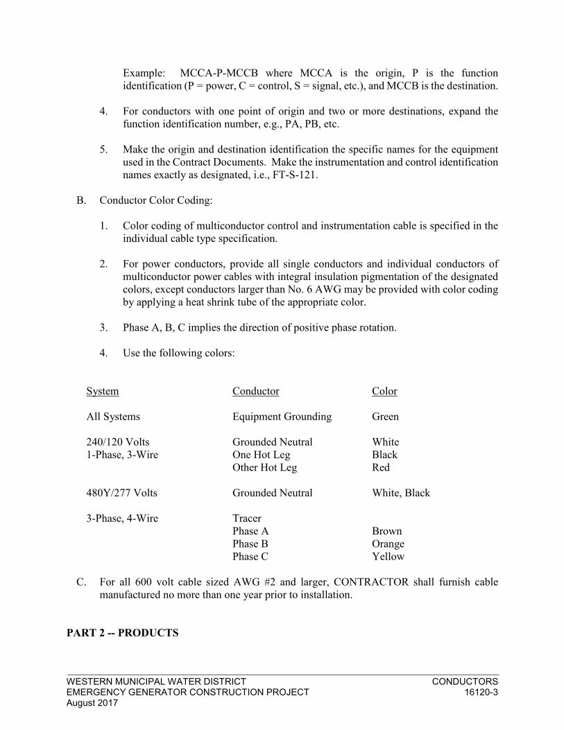
WESTERN MUNICIPAL WATER DISTRICT CONDUCTORS EMERGENCY GENERATOR CONSTRUCTION PROJECT 16120-3 August 2017
Example: MCCA-P-MCCB where MCCA is the origin, P is the function
identification (P = power, C = control, S = signal, etc.), and MCCB is the destination.
4. For conductors with one point of origin and two or more destinations, expand the
function identification number, e.g., PA, PB, etc.
5. Make the origin and destination identification the specific names for the equipment
used in the Contract Documents. Make the instrumentation and control identification
names exactly as designated, i.e., FT-S-121.
B. Conductor Color Coding:
1. Color coding of multiconductor control and instrumentation cable is specified in the
individual cable type specification.
2. For power conductors, provide all single conductors and individual conductors of
multiconductor power cables with integral insulation pigmentation of the designated
colors, except conductors larger than No. 6 AWG may be provided with color coding
by applying a heat shrink tube of the appropriate color.
3. Phase A, B, C implies the direction of positive phase rotation.
4. Use the following colors:
System Conductor Color
All Systems Equipment Grounding Green
240/120 Volts Grounded Neutral White
1-Phase, 3-Wire One Hot Leg Black
Other Hot Leg Red
480Y/277 Volts Grounded Neutral White, Black
3-Phase, 4-Wire Tracer
Phase A Brown
Phase B Orange
Phase C Yellow
C. For all 600 volt cable sized AWG #2 and larger, CONTRACTOR shall furnish cable
manufactured no more than one year prior to installation.
PART 2 -- PRODUCTS
WESTERN MUNICIPAL WATER DISTRICT CONDUCTORS EMERGENCY GENERATOR CONSTRUCTION PROJECT 16120-4 August 2017
2.1 GENERAL
A. The use of a manufacturer's name and model or catalog number is for the purpose of
establishing the standard of quality and general configuration desired only. Products of
other manufacturers will be considered in accordance with the GENERAL
REQUIREMENTS.
2.2 CONDUCTORS
A. Conductors 600 Volts and Below:
1. Unless otherwise indicated, provide stranded conductors.
2. Provide conductors with Type THHN/THWN insulation.
3. Use only copper conductors.
5. Where flexible cords and cables are specified, provide Type SO, 600-volt, with the
number and size of copper conductors indicated.
6. Conductors for applications of 600 volts and below shall be rated for 600 volts unless
otherwise specified.
7. The name of the manufacturer, insulation type, voltage rating and wire size shall be
clearly and permanently imprinted throughout the length of each conductor. All
conductors and cables supplied shall bear the UL label.
B. Multi-Conductor Cable:
1. Provide cable that is UL listed Type TC and conforms to the requirements of UL 1277
and NEC Article 340, or UL listed Power Limited Circuit Cable that conforms to the
requirements of Article 725 of the LAEC. Provide cables permanently and legibly
marked with the manufacturer's name, the maximum working voltage for which the
cable was tested, the type of cable, and labeled UL (or submit evidence of UL listing).
2. Provide cables as specified under the type number in this section (Type 1, Type 2,
etc.). Conduits shown on the Drawings and in the Circuit/Raceway Schedule have
been sized to accommodate the outside diameter for each type. For this reason, use
cable diameters equal to or less than the diameters specified.
a. Type 1 (600-Volt Multi-Conductor Control Cable, Type TC):
(1) General: Multi-conductor control circuit interconnection cable with
ground. Suitable for installation in open air, in cable trays, conduit, or other
approved raceways. Maximum cable temperature rating 90 degrees C dry
locations, 75 degrees C wet locations. Passes vertical tray flame test.

WESTERN MUNICIPAL WATER DISTRICT CONDUCTORS EMERGENCY GENERATOR CONSTRUCTION PROJECT 16120-5 August 2017
(2) Individual Conductors: No. 14 AWG, 7-strand copper.
(3) Insulation and Jackets: Provide conductors having 15-mil PVC insulation
with 4-mil nylon jacket, and UL listed as Type THHN/THWN. Color code
the conductor group in accordance with ICEA S-61-402, Appendix K,
Method 1, Table K-2. Include one full size green equipment grounding
conductor. Bind conductor group with a spiral wrap of barrier tape. Provide
cable with overall outer PVC jacket which is flame-retardant, sunlight- and
oil-resistant, and has a nominal thickness as shown in the table below.
(4) Manufacturers: The Okonite Company, Rome Cable, or equal.
b. Type 3 (600-Volt No. 16 AWG Twisted, Shielded Pair Instrumentation
Cable, Type TC) (UL 62 & 1277):
(1) General: Single pair instrumentation cable designed for noise rejection
for process control, computer, or data log applications. Suitable for
installation in cable trays, conduit, or other approved raceways.
Maximum cable temperature rating shall be 90 degrees C dry locations,
75 degrees C wet locations.
(2) Individual Conductors: Bare soft annealed copper, Class B, 7-strand
concentric per ASTM B 8; 20 AWG, 7-strand tinned copper drain wire.
(3) Insulation and Jacket: Each conductor 15-mil nominal PVC and 4-mil
nylon insulation. Pair conductors pigmented black and red. Jacket
flame-retardant and sunlight- and oil-resistant PVC with 45 mils
nominal thickness. Shield 1.35-mil aluminum/mylar overlapped to
provide 100 percent coverage.
(4) Dimension: 0.31 inch nominal OD.
(5) Manufacturers: The Okonite Company, Alpha Wire Corporation,
Belden or equal.
c. Type 4 (600-Volt No. 16 Twisted, Shielded Triad Instrumentation Cable,
Type TC) (UL 62 & 1277):
(1) General: Single triad instrumentation cable designed for noise rejection
for process control, computer, or data log applications. Suitable for
installation in cable tray, conduit, or other approved raceways.
Maximum cable temperature rating shall be 90 degrees C dry locations,
75 degrees C wet locations.
(2) Conductors: Bare soft annealed copper, Class B, 7-strand concentric per

WESTERN MUNICIPAL WATER DISTRICT CONDUCTORS EMERGENCY GENERATOR CONSTRUCTION PROJECT 16120-6 August 2017
ASTM B 8; 20 AWG, 7-strand, tinned copper drain wire.
(3) Insulation and Jacket: Each conductor, 15-mil nominal PVC and 4-mil
nylon insulation. Triad conductors pigmented black, red, and blue.
Jacket flame-retardant and sunlight- and oil-resistant PVC with 45 mils
nominal thickness. Shield 1.35-mil aluminum/mylar, overlapped to
provide 100 percent coverage.
(4) Dimension: 0.32 inch nominal OD.
(5) Manufacturers: The Okonite Company, Alpha Wire Corporation,
Belden or equal.
d. Type 5 (600-Volt No. 18 AWG, Multi-twisted Shielded Pairs with a
Common Overall Shield Instrumentation Cable, Type TC)(UL 62 & 1277):
(1) General: Twisted, shielded pairs of instrument cables, grouped in a
single cable, designed for use as instrumentation, process control, and
computer cable. Suitable for installation in cable tray, conduit, or other
approved raceways. Maximum cable temperature rating shall be
90 degrees C dry locations, 75 degrees C wet locations.
(2) Conductors: Bare soft annealed copper, Class B, 7-strand, concentric
per ASTM B 8. Tinned copper drain wires. Pair drain wire size
AWG 20, group drain wire size AWG 18.
(3) Insulation and Jacket: Each conductor 15-mil PVC and 4-mil nylon
insulation. Pair conductors pigmented black and red with red conductor
numerically printed for group identification. Outer jacket flame-
retardant and sunlight- and oil-resistant PVC with nominal thickness as
shown in table. Individual pair shield 1.35-mil aluminum/mylar. Group
shield 2.35-mil aluminum/mylar, overlapped for 100 percent coverage.
(4) Dimensions as noted in table below:
Number Maximum Outside Nominal Jacket
of Pairs Dimension (inches) Thickness (mils)
4 0.50 45
8 0.68 60
12 0.82 60
16 0.95 80
20 1.05 80
24 1.16 80
36 1.33 80
50 1.56 80

WESTERN MUNICIPAL WATER DISTRICT CONDUCTORS EMERGENCY GENERATOR CONSTRUCTION PROJECT 16120-7 August 2017
(5) Manufacturers: The Okonite Company, Alpha Wire Corporation,
Belden or equal.
C. Conductor and Cable Tags:
1. Tags relying on adhesives or taped-on markers are not acceptable.
2. Provide conductor tags for conductors No. 12 AWG and below with legible
permanent sleeve of yellow or white PVC with machine printed black marking.
3. Provide tags for cables, and for conductors No. 10 AWG and larger, consisting of
permanent nylon marker plates with legible designations hot stamped on the plate.
Attach these marker plates to conductors and cables with nylon tie cord.
D. Equipment Grounding Conductors:
1. Provide soft-drawn copper conductors, not smaller than #12 AWG and as indicated
or as required by NEC, for equipment grounding.
2. Provide conductors with green insulation of the same type as all other circuit wires.
E. Direct Buried Grounding Conductors:
1. Provide bare stranded copper conductors, size as indicated, for the ground system
grid at transformers, switchgear, and where indicated.
PART 3 -- EXECUTION
3.1 GENERAL
A. Do not exceed cable manufacturer's recommendations for maximum pulling tensions
and minimum bending radii. Where pulling compound is used, use only UL listed
compound compatible with the cable outer jacket and with the raceway involved.
contractor shall perform and submit pulling calculation per manufacturers
recommendation to ascertain that there is no overstrain to the cable. The calculation
shall be submitted to the ENGINEER for approval.”
B. Tighten all screws and terminal bolts using torque type wrenches and/or drivers to
tighten to the inch-pound requirements of the NEC and UL.
C. Single conductors and cables in maintenance holes, handholes, vaults, cable trays, and
other indicated locations shall be wrapped together by arc and fireproofing tapes, and
shall be bundled throughout their exposed length with nylon, self-locking, releasable,
cable ties placed at intervals not exceeding 18 inches on centers.

WESTERN MUNICIPAL WATER DISTRICT CONDUCTORS EMERGENCY GENERATOR CONSTRUCTION PROJECT 16120-8 August 2017
D. Wires and cables in each voltage classification shall be installed in separate raceways
and shall be completely isolated at the cable and wire terminations.
E. No vehicles shall be used to pull conductors.
F. A means of monitoring cable tension shall be provided at all pulls. (I.e. dynamometer)
3.2 CONDUCTOR 600 VOLTS AND BELOW
A. Provide conductor sizes indicated on Drawings.
B. Wire nuts may be used on solid conductors of 120-volt and 277-volt lighting and 120-
volt receptacle circuits only. Place no more than one conductor in any single-barrel
pressure connection. Use crimp connectors with tools by same manufacturer and/or UL
listed for connectors of all stranded conductors.
C. Soldered mechanical joints insulated with tape will not be acceptable.
D. Vinyl plastic insulating tape for wire and cable splices and terminations shall be flame
retardant, 7-mil thick minimum, rated for 90 degrees C minimum meeting the
requirements of UL 510.
E. Provide terminals and connectors acceptable for the type of material used.
F. Arrange wiring in cabinets, panels, and motor control centers neatly cut to proper length,
remove surplus wire, and bridle and secure in an acceptable manner. Identify all circuits
entering motor control centers or other control cabinets in accordance with the
conductor identification system specified herein.
G. Terminate control and instrumentation wiring with methods consistent with terminals
provided, and in accordance with terminal manufacturer's instructions. Where terminals
provided will accept such lugs, terminate all control and instrumentation wiring (except
solid thermocouple leads) with insulated, locking-fork compression lugs, Thomas &
Betts Sta-Kon or equal.
H. For terminals designed to accept only bare wire compression terminations, use only
stranded wire, and terminate only one wire per terminal. Tighten all terminal screws
with torque screwdriver to recommended torque values.
I. Attach compression lugs with a tool specifically designed for that purpose which
provides a complete, controlled crimp where the tool will not release until the crimp is
complete. Use of plier type crimpers is not acceptable.
J. Cap spare conductors and conductors not terminated with UL listed end caps.
K. Where conductors pass through holes or over edges in sheet metal, remove all burrs,

WESTERN MUNICIPAL WATER DISTRICT CONDUCTORS EMERGENCY GENERATOR CONSTRUCTION PROJECT 16120-9 August 2017
chamfer all edges, and install bushings and protective strips of insulating material to
protect the conductors.
L. For conductors that will be connected by others, provide at least 6 feet spare conductor
in freestanding panels and at least 2 feet spare in other assemblies. Provide more spare
conductor in any particular assembly where it is obvious that more conductor will be
needed to reach the termination point.
M. CONTRACTOR shall provide cable pulling tension calculations for review and
approval before pulling cables sized 4/0 and larger.
3.3 CONDUCTORS ABOVE 600 VOLTS
A. Splices will not be permitted unless specifically indicated or approved by the
ENGINEER.
B. Make all joints and terminations with high voltage splice and termination kits specified
herein and in accordance with splice or termination manufacturer's instructions. Once
started, install splices or terminations as a continuous operation.
C. Identify all circuits in accordance with the conductor identification system specified at
load centers, maintenance holes, splices, terminations, etc.
D. Provide terminals or connectors acceptable for the type of conductor material used.
E. Give 2 working days notice to the ENGINEER and the INSPECTOR prior to the making
of joints or terminations.
F. Cable splices shall be made by qualified cable splicers in accordance with the
recommendations of the manufacturer. CONTRACTOR shall furnish documentation
detailing the qualifications of each cable splicer to be working on the job.
G. CONTRACTOR shall provide cable pulling tension calculations prior to pulling any
medium or high voltage cable.
3.4 CABLES
A. Do not splice without permission of the ENGINEER or the INSPECTOR. Locate
splices, when permitted, only in readily accessible cabinets or junction boxes using
terminal strips. Splices will not be permitted unless deemed necessary by approved
pulling tension calculations.
B. Where connections of cables installed under this section are to be made under Division
Instrumentation and Controls, leave pigtails of adequate length for neat bundled type
connections.

WESTERN MUNICIPAL WATER DISTRICT CONDUCTORS EMERGENCY GENERATOR CONSTRUCTION PROJECT 16120-10 August 2017
C. Instrumentation, computer, and control cables run under infinite access floors in control
rooms may be installed under the floor without protection. Run individual wires, pairs,
or triads in flex conduit under the floor or grouped into bundles at least ½ inch in
diameter.
D. Maintaining the integrity of shielding of instrumentation cables is essential to the
operation of the control systems. Take special care in cable installation to ensure that
grounds do not occur because of damage to the jacket over the shield.
E. Cables entering maintenance holes, handholes or vaults shall be sealed using an
expanding foam product approved for the purpose.
3.5 CONDUCTOR ARC AND FIREPROOFING TAPES
A. Use arc and fireproofing tapes on all 600-volt single conductors and cables except those
rated Type TC at splices in all maintenance holes, handholes, vaults, cable trays, and
other indicated locations.
B. Wrap together as a single cable all conductors entering from each conduit.
C. Follow tape manufacturer's installation instructions. Secure the arc and fireproofing
tape at frequent intervals with bands of the specified glass cloth electrical tape. Make
each band of at least two wraps of tape directly over each other.
D. Wrap together as far as possible, conductors carrying phases A, B, and C of the same
feeder. Do not wrap together conductors carrying only two of the three phases.
E. The cables shall be trained as closely as possible to their final positions.
F. The cables shall be cleaned of all oil, grease, and cable pulling compounds using suitable
solvents and cleaners non-injurious to cable and then wiped completely dry.
G. Any projecting surfaces such as fittings, ground connectors or bonding connections
shall be covered with an insulating compound to present a smooth continuous surface
for taping.
H. Fireproofing tapes shall be submitted as shop drawings for approval. Tapes shall be 3-
inch width half-lapped and extend a minimum of 6-inches into the raceway. Use ¾”
glass tape at three foot intervals to hold tape in place.
3.6 FIELD TESTS
A. Field test shall be performed on conductors in accordance with Section 16030 Electrical
Tests.

WESTERN MUNICIPAL WATER DISTRICT CONDUCTORS EMERGENCY GENERATOR CONSTRUCTION PROJECT 16120-11 August 2017
END OF SECTION

WESTERN MUNICIPAL WATER DISTRICT CABINETS AND ENCLOSURES
EMERGENCY GENERATOR CONSTRUCTION PROJECT 16170-1
August 2017
SECTION 16170
CABINETS AND ENCLOSURES
PART 1 - GENERAL
1.1 GENERAL CONDITIONS:
A. See the Conditions of the Contract (General, Supplementary and Special Conditions) and the General Requirements (Division 1).
1.2 WORK INCLUDED:
A. This section covers all equipment cabinets and enclosures as shown on the drawings or as required to house the specified devices and equipment. The work under this section consists of furnishing materials and equipment, performing labor and services necessary for the installation of the cabinets and enclosures required for the security system.
1.3 RELATED WORK SPECIFIED ELSEWHERE:
A. Refer to all other Division 16 specification sections and drawings, and to the specifications and drawings under the General Construction Contract to ascertain the extent of work included.
1.4 REFERENCED SPECIFICATIONS, MATERIALS AND/OR CODES:
A. California Electrical Code (CEC)
1.5 COOPERATION WITH OTHER TRADES:
A. The Contractor shall coordinate the work of the section with that of other sections as required to ensure that the entire work of this Project will be carried out in an orderly, complete and coordinated fashion.
1.6 SUBMITTALS:
A. General: Submittals shall be made in accordance with the General Provisions (Section 16000) of these specifications.
PART 2 - PRODUCTS
2.1 MATERIALS:
A. Cabinets - Wall Mounted:
1. All equipment cabinets installed indoors shall be NEMA 1 enclosures.
2. All equipment cabinets installed outside or exposed to weather shall be NEMA 3 enclosures.

WESTERN MUNICIPAL WATER DISTRICT CABINETS AND ENCLOSURES
EMERGENCY GENERATOR CONSTRUCTION PROJECT 16170-2
August 2017
3. Cabinets shall be constructed of 14 gauge rolled steel.
4. Cabinet doors shall be furnished with key lockable doors with all cabinets under Division 16 keyed alike.
5. All cabinets shall be furnished with removable steel back panels for mounting equipment.
6. Cabinets shall be furnished with appropriate size and quantity of knock-outs for conduit entry.
7. Cabinets shall be grounded as specified in Section 16450.
8. Cabinets shall be provided with adequate vents.
9. All cabinets shall be furnished with white-on- black laminated plastic name plates identifying each cabinet as noted on the drawings. Lettering shall be minimum 3/16” high.
10. Cabinet finish shall be ANSI 61 gray inside and out.
11. Cabinets shall be sized in strict accordance with the CEC.
12. Cabinet back panels shall be furnished with a ground buss bar.
13. Door size shall be selected to allow a minimum door swing of 90 degrees within the dimensional constraints of the equipment room.
14. Cabinets shall be equipped with index card holders and cards mounted behind heavy plastic on inside of cabinet doors.
15. Affix nameplates to cabinet doors with a minimum of two escutcheon pins or screws.
B. Vertical Cabinet - Floor Mounted:
1. All free-standing floor mounted type shall have features and/or characteristics as follows:
a. Panel Width - not less than 20"
b. Panel Height - not more than 78-3/4"
c. Overall Height - not more than 87"
d. Overall Depth - 25" Nominal
e. Rear Door - Vented, except as otherwise specified.
f. Front door with vents at top and bottom, except as otherwise specified.
g. Plain top panel with sunshield on all sides when installed outdoor without shade.

WESTERN MUNICIPAL WATER DISTRICT CABINETS AND ENCLOSURES
EMERGENCY GENERATOR CONSTRUCTION PROJECT 16170-3
August 2017
h. Frame- 14 ga. CRS
i. Side panels - 18 ga.
j. Styled frames with trim
k. 19" EIA adjustable mounting rails for front and rear equipment mounting
l. Locks - all cabinets to be keyed alike
m. Units shall be pre-assembled type
n. Color - ANSI 61
2. Cabinets grouped side-by-side shall have side panels on each section.
PART 3 - EXECUTION
3.1 EXECUTION:
A. Cabinets:
1. Provide cabinets as necessary for proper installation of the equipment specified and in compliance with all codes and regulations.
2. Secure all cabinets in place with lead shield anchors and lag bolts.
3. Unused openings in cabinets shall be closed to afford protection equivalent to that of the wall of the cabinet.
B. Ventilation:
1. Furnish and install ventilation fans, vents, and filters for all cabinets where forced air cooling is required to maintain interior cabinet temperature at or below 95°F.
2. For cabinets with forced ventilation, doors and side panels shall be solid with no louvers.
3. Division 17 Subcontractor shall select vented vs. forced air cabinets based on the environment's conditions of the equipment room and equipment to be installed in each cabinet.
3.2 COMPLETION:
A. General:
1. Upon completion of the work, remove excess debris, materials, equipment,
apparatus, tools and the like and leave the premises clean, neat and orderly.
2. All cables shall be dressed neatly in each cabinet and enclosure. Excess cable
shall be trimmed and disposed of.

WESTERN MUNICIPAL WATER DISTRICT CABINETS AND ENCLOSURES
EMERGENCY GENERATOR CONSTRUCTION PROJECT 16170-4
August 2017
END OF SECTION

WESTERN MUNICIPAL WATER DISTRICT EMERGENCY – STANDBY STATIONARY GENERATOR LAKE HILLS 1860 BPS GENERATOR 16410-1 August 2017
SECTION 16410
EMERGENCY - STANDBY STATIONARY GENERATORS
PART 1 - GENERAL
1.1 THE REQUIREMENT
A. The Contractor shall supply one (1) stationary Caterpillar 350 kW/437.5 KVA diesel
generator model C13, Feature Code C13DE50 as permitted by SCAQMD for the Lake
Hills 1860 BPS for the District. Contractor shall obtain a copy of the permit to ascertain
the generator being supplied is the same as permitted by SCAQMD.
B. The District has applied and obtained the necessary permits from SCAQMD for permit to
construct and permit to operate the generator. The permits are included herein for
Contractors review. The Contractor shall be responsible for obtaining the proper generator
which has been permitted by SCAQMD.
C. The Contractor shall furnish all tools, equipment, materials, and supplies and shall perform
all labor required to complete the work as indicated on the Drawings and specified herein.
D. The Contractor shall provide a full tank of fuel prior to final acceptance.
E. This section covers the work necessary to complete the standby engine power generating
system.
1.2 RELATED WORK SPECIFIED ELSEWHERE
The WORK of the following Sections and Division applies to the WORK of this Section.
Other Sections of the Specifications, not referenced below, shall also apply to the extent
required for proper performance of this WORK.
1. Section 03300 Cast-in-Place Concrete.
2. Section 16030 Electrical Testing Requirements.
3. Section 16100 Basic Materials and Methods.
4. Section 16110 Raceways
5. Section 16150 Conductors
6. Section 16300 Grounding.
1.3 REFERENCE SPECIFICATIONS, CODES AND STANDARDS
A. All work specified herein shall conform to or exceed the applicable requirements of the
referenced portions of the following publications to the extent that the provisions thereof
are not in conflict with other provisions of these specifications.
B. Comply with the current provisions of the following Codes and Standards.

WESTERN MUNICIPAL WATER DISTRICT EMERGENCY – STANDBY STATIONARY GENERATOR LAKE HILLS 1860 BPS GENERATOR 16410-2 August 2017
1. Codes and Standards:
CEC California Electrical Code, latest adopted edition.
2. Government Standards:
FS W-C-596E/GEN (1) Connector, Plug, Receptacle and Cable Outlet, Electrical
Power.
FS W-S-896E/GEN (1) Switches, Toggle (Toggle and Lode), Flush Mounted
(ac).
FS WW-C-581E Conduit, Metal, Rigid, And Intermediate; And Coupling,
Elbow, and Nipple, Electrical Conduit: Steel, Zinc
Coated.
3. Commercial Standards:
ANSI B16.5 Pipe Flanges and Flanged Fittings, Steel, Nickel Alloy,
and Other Special Alloys.
ANSI C80.1 Rigid Steel Conduit, Zinc Coated, specification for.
ANSI Z55.1 Gray Finishes for Industrial Apparatus and Equipment.
ANSI/UL 467 Grounding and Bonding Equipment, Safety Standard
For.
ICEA S-61-402 Thermoplastic - Insulated Wire and Cable for the
Transmission and Distribution of Electrical Energy.
ICEA S-19 Rubber - Insulated Wire and Cable for the Transmission
and Distribution of Electrical Energy.
C. All equipment furnished by the CONTRACTOR shall be listed by and shall bear the label
of Underwriters' Laboratories, Incorporated, (UL) or of an independent testing laboratory
acceptable to the local Code-enforcement agency having jurisdiction.
D. The construction and installation of all electrical equipment and materials shall comply
with all provisions of the Cal/OSHA Safety Orders (Title 8, CCR) State Building
Standards, and applicable local codes and regulations.
1.4 SUBSTITUTION
A. Proposed deviations from the specifications shall be treated as follows:
1. Substitution Time Requirement

WESTERN MUNICIPAL WATER DISTRICT EMERGENCY – STANDBY STATIONARY GENERATOR LAKE HILLS 1860 BPS GENERATOR 16410-3 August 2017
2. Requests for substitutions shall be made a minimum of ten (10) days prior to bid date.
Manufacturers catalog data shall accompany each request and authorized acceptance
shall be addenda only.
B. Substitution Responsibility
1. The power system has been designed to the specified manufacturer's electrical and
physical characteristics. The equipment sizing, spacing, amounts, electrical wiring,
and other characteristics have all been sized and designed around CATERPILLAR
supplied equipment. Should any substitutions be made, the bidder shall bear
responsibility for the installation, coordination and operation of the system as well as
any engineering and redesign costs, which may result from such substitutions.
1.5 CONTRACTOR SUBMITTALS
A. Submittals shall be made in accordance with Section 01300 Submittals and Section 16010
General Electrical Requirements.
1.6 QUALITY ASSURANCE
A. Quality assurance shall be in accordance with all applicable requirements of Section 16010
General Electrical Requirements.
B. Guarantee/Warranty:
C. The manufacturer shall warrant for one year from date of acceptance of installation that
equipment and systems will be free from defects in material and workmanship if properly
installed, maintained, and operated in accordance with manufacturer's instruction manuals.
PART 2 - PRODUCTS
ENGINE FOR THE 350 KW GENERATOR
A. General: The Contractor shall responsible for obtaining the proper engine as permitted by
SCAQMD. The permit is included herein for Contractor’s review. The general design of
the engines furnished shall be the standards of the various manufacturers, except where
these differ from the requirements of these Specifications. The design shall be such as to
provide adequate strength of all parts for the specified duty. The complete engine generator
unit shall be mounted on a common steel sub base.
B. Engine: The engine shall be the full four-cycle diesel type suitable for a standby output of
350 kW, 437.5 KVA, 0.8 PF when driving a synchronous generator at a speed not
exceeding 1800 rpm. Horsepower ratings shall be adequate for 500 feet above sea level
operation. Engine may be supercharged or naturally aspirated. Engine may be
turbocharged, equipped with an intercooler and/or aftercooler of not fewer than eight (8)
and not more than sixteen (16) cylinders.
C. Starting System: The engine shall be equipped with automatic starting by a 12-volt or a
24-volt battery driven starter acting in response to the automatic starting panel, hereinafter

WESTERN MUNICIPAL WATER DISTRICT EMERGENCY – STANDBY STATIONARY GENERATOR LAKE HILLS 1860 BPS GENERATOR 16410-4 August 2017
specified. Batteries shall be 200 amp-hour capacity and the 24-volt system may be either
one 24-volt or two 12-volt batteries in series. The batteries shall be housed in an acid-
resistant frame, or box, which shall be mounted on a concrete pad adjacent to the engine.
Location of the battery container shall not interfere with maintenance and inspection of the
engine.
Fuel and Governing System:
1. Generator shall have an integral sub-base fuel tank rated for 24-hour operation at full
load.
2. The governor shall be either mechanical or hydraulic and shall provide not more than
5 percent regulation over the speed range. Governor adjustment shall be by means of
an external vernier scale. An overspeed trip shall be provided.
Cooling System:
1. The jacket water cooling system shall consist of an engine mounted radiator with jacket
water pump, fan, assembly, and fan guard. The radiator shall be fitted with a duct
flange outlet. The connecting ductwork is to be provided under another section.
2. Provide an engine thermostat to regulate engine water temperature as recommended by
the manufacturer. Provide a high-coolant temperature device to shut down the engine
through the engine control panel when the engine temperature exceeds 200 degrees F.
Jacket water heaters suitable for operation on 120-volt, 60-Hz current shall be provided
to maintain engine water temperature at 120 degrees F with an ambient temperature of
50 degrees F. Heaters shall be thermostatically controlled. The engine cooling system
shall be filled with a mixture of water and permanent type antifreeze to protect the
system to a temperature of -10 degrees F.
Lubricating System:
1. The engine lubricating system shall be full-pressure type with a device to shut down
the engine through the engine control panel on low oil pressure. Provide an oil filter
with replaceable element and a bayonet type oil level stick. Provide a valved oil drain
extension as shown.
2. Lubrication oil shall be cooled by a water-cooled pressurized type heat exchanger
utilizing jacket water.
Exhaust System: The muffler shall be rated for critical silencing. Exhaust pipe shall be
Schedule 40 steel pipe conforming to ASTM A 53. Fittings shall be either screwed cast
iron or Schedule 40 butt welding type. Connection of the exhaust pipe to the engine shall
be by means of a flanged, flexible, corrugated, stainless steel pipe especially suited for
diesel exhaust service. Flexible length shall be 18 inches.
Air Intake System: The engine air intake shall be equipped with a dry type air cleaner
with filter service indicator.
Engine Instrumentation: Instrumentation to be provided shall include an oil pressure
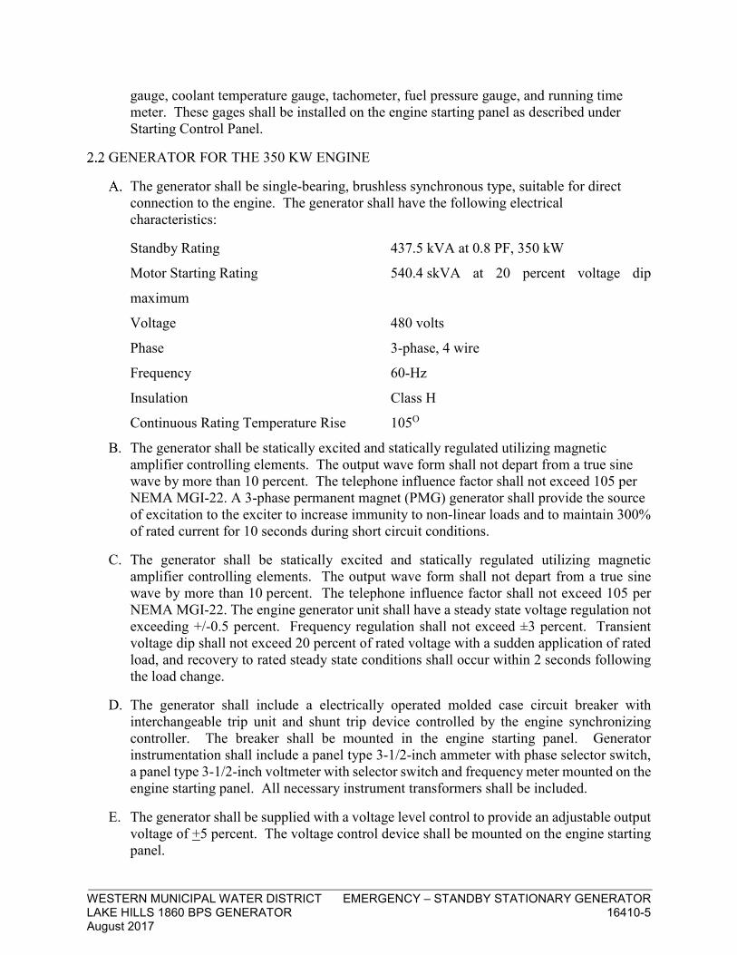
WESTERN MUNICIPAL WATER DISTRICT EMERGENCY – STANDBY STATIONARY GENERATOR LAKE HILLS 1860 BPS GENERATOR 16410-5 August 2017
gauge, coolant temperature gauge, tachometer, fuel pressure gauge, and running time
meter. These gages shall be installed on the engine starting panel as described under
Starting Control Panel.
GENERATOR FOR THE 350 KW ENGINE
The generator shall be single-bearing, brushless synchronous type, suitable for direct
connection to the engine. The generator shall have the following electrical
characteristics:
Standby Rating 437.5 kVA at 0.8 PF, 350 kW
Motor Starting Rating 540.4 skVA at 20 percent voltage dip
maximum
Voltage 480 volts
Phase 3-phase, 4 wire
Frequency 60-Hz
Insulation Class H
Continuous Rating Temperature Rise 105O
B. The generator shall be statically excited and statically regulated utilizing magnetic
amplifier controlling elements. The output wave form shall not depart from a true sine
wave by more than 10 percent. The telephone influence factor shall not exceed 105 per
NEMA MGI-22. A 3-phase permanent magnet (PMG) generator shall provide the source
of excitation to the exciter to increase immunity to non-linear loads and to maintain 300%
of rated current for 10 seconds during short circuit conditions.
C. The generator shall be statically excited and statically regulated utilizing magnetic
amplifier controlling elements. The output wave form shall not depart from a true sine
wave by more than 10 percent. The telephone influence factor shall not exceed 105 per
NEMA MGI-22. The engine generator unit shall have a steady state voltage regulation not
exceeding +/-0.5 percent. Frequency regulation shall not exceed ±3 percent. Transient
voltage dip shall not exceed 20 percent of rated voltage with a sudden application of rated
load, and recovery to rated steady state conditions shall occur within 2 seconds following
the load change.
D. The generator shall include a electrically operated molded case circuit breaker with
interchangeable trip unit and shunt trip device controlled by the engine synchronizing
controller. The breaker shall be mounted in the engine starting panel. Generator
instrumentation shall include a panel type 3-1/2-inch ammeter with phase selector switch,
a panel type 3-1/2-inch voltmeter with selector switch and frequency meter mounted on the
engine starting panel. All necessary instrument transformers shall be included.
E. The generator shall be supplied with a voltage level control to provide an adjustable output
voltage of +5 percent. The voltage control device shall be mounted on the engine starting
panel.

WESTERN MUNICIPAL WATER DISTRICT EMERGENCY – STANDBY STATIONARY GENERATOR LAKE HILLS 1860 BPS GENERATOR 16410-6 August 2017
PARTICULATE FILTER
A. Passive Diesel Particulate Filter: Generator shall be equipped with a passive diesel
particulate filter that complies with the current SCAQMD regulations. Filter shall be
mounted above and supported by the generator enclosure. Access to the generator and
engine shall not be hindered by the installation of the filter. Passive diesel particulate filter
shall be Johnson Matthey or Miratech as recommended by the generator manufacturer.
SOUND ATTENUATED ENCLOSURE
A. Sound attenuated drip-proof, weather protective enclosure shall be constructed of 0.063”
(14 gauge equivalent) marine grade 5052 aluminum alloy. The enclosure shall be primed
and finish coated with powder baked paint. The paint color shall be standard manufacturer
color. The enclosure shall be fabricated and mounted to the sub-base fuel tank by the
generator manufacturer. The enclosure roof shall be peaked to direct water runoff away
from all components.
B. Two doors per side and one rear door shall be provided for operator and service access.
Hinges shall allow the doors to swing open or be removed easily for access and service.
Access to the controller and main line circuit breaker must meet the requirements of the
National Electric Code (current edition accepted by jurisdiction having authority). All door
locks shall be stainless steel and shall be keyed alike.
C. Exhaust piping and internally insulated super critical grade silencer shall be mounted inside
the enclosure.
D. Cooling and combustion air shall enter the enclosure through wire screened panels. Engine
exhaust gases and cooling air shall discharge vertically through a screened opening.
E. Sound shall be reduced by UL approved polyether acoustic material with protective facing
film which is securely attached to the enclosure interior. Sound shall not exceed 70 dBA,
23 feet from the enclosure center with the generator set operating at full load. Sound
enclosure shall be Level 2 per manufacturer’s standard enclosures.
Enclosure manufacturer shall provide all necessary hardware to internally mount the
specified exhaust silencer(s) and maintain the weatherproof integrity of the system.
Silencer and exhaust flex shall be insulated. Include a 10’ stainless steel concentric
exhaust extension when required by local code.
TORSIONAL VIBRATION
The complete engine generator set shall be so designed, constructed, and installed as to
be free from objectionable vibration in any mode. Freedom from torsional vibration shall
be demonstrated by torsiograph records taken during the factory test of this or a similar
unit.
FACTORY PAINT
A. The complete engine generator set, including the instrument panel, shall be given a
factory-applied primer and two finish coats of the manufacturer's standard heat-resistant

WESTERN MUNICIPAL WATER DISTRICT EMERGENCY – STANDBY STATIONARY GENERATOR LAKE HILLS 1860 BPS GENERATOR 16410-7 August 2017
engine paint. The color shall be as selected by the ENGINEER. All areas damaged
during shipment shall be touched up after installation.
STARTING CONTROL PANEL FOR GENERATOR
Generator control panel shall be Caterpillar EMCP 4.4 or equal.
When engine fires, starting control shall automatically disconnect cranking control and
prevent recranking for a definite period of time after engine stops.
4 cranking cycles of 10 seconds ON, 10 seconds OFF shall be provided prior to lockout
on overcranking.
Fault indicating lamps on the panel shall be of the push-to test type and shall indicate low
oil pressure, high water temperature, overspeed, and overcrank. The engine shall shut
down under any of these conditions and may not be restarted until the system is manually
reset. Provide a contact in the panel which closes under any alarm condition and a
contact which closes to indicate that the engine is running. Provide Ethernet
communication card for monitoring status and alarms via existing SCADA system.
Provide necessary software and drivers if necessary. Existing SCADA utilizes
Wonderware HMI.
A four-position selector switch shall be provided in the panel for HANDCRANK, STOP,
AUTOMATIC, and ENGINE TEST.
A battery charger, suitable for operation on 120-volt input power, with an adjustable
0.05-amp to 2.0-amp charging rate shall be furnished within the starting panel. The
charger shall have an ammeter to indicate charging rate which shall be mounted on the
face of the cranking panel and match the generator instrumentation.
The starting control panel shall have sufficient space to permit mounting of the engine
and generator instrumentation specified above on the face. All instruments shall be
identified either on the instrument face or by engraved, black, laminated plastic
nameplates with white 1/4-inch high letters. Inscriptions shall be as directed by the
ENGINEER. Provide a thermostat controlled space heater for the Control panel
enclosure.
Emergency Stop: Provide an emergency stop on each of the generators at an easily
accessible and conspicuous location.
FUEL STORAGE TANK
The atmospheric package double wall tank systems shall be of extra heavy construction
with all components assembled, mounted, wired and plumbed on the tank by the
manufacturer. Each tank shall be tested as a complete package prior to shipping from the
factory. The tank shall be UL listed.
B. Fuel Tank: Mounted above grade, factory-fabricated assembly of a Nationally Recognized
Testing Laboratory listed fuel tank with integral, float-controlled transfer pump and the
following features:

WESTERN MUNICIPAL WATER DISTRICT EMERGENCY – STANDBY STATIONARY GENERATOR LAKE HILLS 1860 BPS GENERATOR 16410-8 August 2017
1. Containment: integral rupture basin with a capacity of 110 to 120 percent of nominal
capacity of day tank.
a. Leak detector: locate in rupture basin and connect to provide audible and visual
alarm in the event of a tank leak.
2. Tank Capacity: 24-hours at full load.
3. Pump Capacity: Exceeds maximum flow of fuel drawn by engine-mounted fuel supply
pump at 110 percent of rated capacity, including fuel returned from engine.
4. Unit, Including Alarm Contacts shall comply with UL 142.
5. Low-Level Warning Sensor: Separate device operates alarm contacts at 75% of max
fuel level.
6. Low-Level Alarm Sensor: Separate device operates alarm contacts at 50% max fuel
level.
7. High-Level Alarm Sensor: Separate device operates alarm and redundant fuel shutoff
contacts at 98% of max fuel level.
8. Piping Connection: Include fuel suction and return lines to fuel storage tank, fuel
supply and return lines to engine, local fuel fill, vent line, overflow line and tank drain
line complete with shut-off valve.
9. Fuel Gauge: Direct recording fuel level gauge.
10. Prove a 2” threaded opening on the top of the day tank to accommodate a fuel oil pump
control probe.
11. Prove a 2” threaded opening on the top of the day tank to accommodate a float for the
mechanical shut-off of the supply fuel upon high level.
TANK VENT CAP
A. OPW No. 23, Buckeye 4103-A, or equal, 1-1/2-inch aluminum vent with brass screen.
Vent cap shall be at least 12 feet above the finish surface or above the bottom of the sub-
base fuel tank.
FOOT VALVE AND EXTRACTOR ASSEMBLY
A. Foot valve shall be 1-1/2-inch OPW Model 22 with double poppet valve with metal-to-
metal seat and 20-mesh Monel screen. Body and poppets shall be constructed of bronze.
B. The extractor assembly shall be OPW 1003 Series with 4-inch OPW 116 pipe cap, 7-1/2-
inch OPW 104A manhole, and 1-1/2-inch OPW 233 extractor fitting.
FILL CONNECTION
A. Provide overfill prevention valve OPW No. 61-ST, Buckeye AZ-0752, or equal, 4-inch

WESTERN MUNICIPAL WATER DISTRICT EMERGENCY – STANDBY STATIONARY GENERATOR LAKE HILLS 1860 BPS GENERATOR 16410-9 August 2017
bronze fill adapter with 4-inch fill cap. Provide a 5-gallon spill containment bucket at the
fill port.
DISCHARGE HEAD BOX
A. Box shall be 22-inch by 22-inch by 10-inch deep galvanized steel box with galvanized
steel cover ACP by Ace Tank and Equipment Company, A.O. Smith 4204, or equal.
FUEL TANK VENTS
A. Provide a 2” black iron vent pipe for the standard fuel tank vent to terminate 12 feet above
finish surface and a 3” black iron vent pipe for the emergency fuel tank vent to terminate
12 feet above finish surface.
GENERATOR MOUNTING PAD
A. Provide a 4” wide and 1” thick mounting pad underneath and all around the perimeter of
the tank. Pad shall be installed seamless to prohibit intrusion of fluid underneath the fuel
tank. Chalk with silicone where the meet prior to the installation of the generator.
Mounting pad shall be CalDyn FP-Pad, 1” ribbed neoprene sandwich pad.
SIGNS
A. Provide a sign on the generator within view of the operator stating “CLASS II
COMBUSTIBLE LIQUID” per CFC 3403.5 and local fire department guidelines.
SPECIAL TOOLS
A. A set of specialty tools necessary for routine maintenance of the equipment shall be
furnished. Included shall be a hydrometer and two-pronged battery voltmeter.
SPARE PARTS
A. The following spare parts shall be furnished in accordance with the provisions of Section
16010 General Electrical Requirements:
1. Three Sets fuel oil filter elements and gaskets
2. Three Lubricating oil filter elements and gaskets
3. One Air cleaner filter element
4. Two Sets packing for each auxiliary pump
5. Two Sets V-belts for fan and pump drives
PART 3 - EXECUTION
3.1 TESTS
A. The engine generator unit shall be tested in accordance with the requirements of Section

WESTERN MUNICIPAL WATER DISTRICT EMERGENCY – STANDBY STATIONARY GENERATOR LAKE HILLS 1860 BPS GENERATOR 16410-10 August 2017
16030 Wastewater Facilities Electrical Testing Requirements or 16570 Municipal
Facilities Electrical Testing Requirements.
3.2 SERVICE
A. The engine-generator supplier shall maintain 24-hour parts and service capability within
100 miles of the buyer’s location. The distributor shall stock parts as needed to support
the generator set package for this specific project. The supplier must carry sufficient
inventory to cover no less than 80% parts service within 24hrs and 95% within 48 hours.
The supplier shall provide factory certified electric power service technicians.
3.3 EXTENDED SERVICE COVERAGE
A. The genset supplier shall provide firm quote for an optional extended service coverage
contract for 5 years and 2500 hours with no deductible. Extended Service Coverage
provides for 100 percent of usual and customary parts and labor costs for failures due to
defects in materials and workmanship to the “as shipped consist” from the factory,
excluding certain items such as trailer components and consumables as outlined in the ESC
contract document up to 8 hours and 320 miles per incident.
END OF SECTION

WESTERN MUNICIPAL WATER DISTRICT GROUNDING EMERGENCY GENERATOR CONSTRUCTION PROJECT 16450-1 August 2017
SECTION 16450
GROUNDING
PART 1 -- GENERAL
1.1 THE REQUIREMENT
A. The CONTRACTOR shall furnish all tools, equipment, materials, and supplies and shall
perform all labor required to complete the work as indicated on the Drawings and specified
herein.
1.2 RELATED WORK SPECIFIED ELSEWHERE
A. The work of the following Divisions and Sections applies to the work of this Section. Other
Division and Sections of the Specifications, not referenced below, shall also apply to the
extent required for proper performance of this work.
1. Division 16 Electrical, applicable sections.
B. Materials, equipment and devices furnished and installed under other Divisions with
raceway and electrical conductors furnished, installed, and connected under Division 16,
Electrical.
1.3 REFERENCED SPECIFICATIONS, CODES AND STANDARDS
A. All work specified herein shall conform to or exceed the applicable requirements of the
referenced portions of the following publications to the extent that the provisions thereof
are not in conflict with other provisions of these specifications.
B. Comply with the current provisions of the following Codes and Standards.
1. Codes and Standards:
CEC California Electrical Code, latest adopted edition.
California Code of Regulations Title 8, Industrial Relations, Subchapter 5, Electrical
Safety Orders.
2. Commercial Standards:
ANSI/UL 467 Safety Standard for Grounding and Bonding Equipment.
IEEE 142 Grounding of Industrial and Commercial Power Systems
C. All equipment furnished by the CONTRACTOR shall be listed by and shall bear the label

WESTERN MUNICIPAL WATER DISTRICT GROUNDING EMERGENCY GENERATOR CONSTRUCTION PROJECT 16450-2 August 2017
of Underwriters' Laboratories, Incorporated, (UL) or of an independent testing laboratory
acceptable to the District.
D. The construction and installation of all electrical equipment and materials shall comply
with all applicable provisions of the CAL OSHA Safety orders. (Title 8 CCR, as
applicable), State Building Standards, and applicable local codes and regulations.
1.4 CONTRACTOR SUBMITTALS
A. Submittals shall be made in accordance with the requirements of Section 16010 Electrical
General Provisions.
B. General Provisions - Submittals shall conform to the requirements of Section 16030
Electrical Tests, Section 16120 Conductors and additional requirements specified herein.
Submittals shall be made for, but not be limited to the following:
1. Catalog literature for all products.
2. Certified copies of ground test results.
3. Field test procedures including lists of test equipment to be used.
1.5 QUALITY ASSURANCE
A. Quality assurance shall be in accordance with the requirements of Section 16010 Electrical
General Provisions and Section 16030 Electrical Tests.
PART 2 -- PRODUCTS
2.1 GROUND CONDUCTORS
A. Provide grounding conductors of the size shown and the type specified in Section 16120,
"Conductors". In no case shall the size of any grounding conductor be less than that
stipulated by the NEC for that specific application.
B. All grounding conductors furnished shall be composed of material resistant to any existing
corrosive conditions or shall be suitably protected against such conditions.
2.2 GROUND CONNECTIONS
A. For below grade connections, provide exothermic-welded connectors.
B. For above grade connections, provide bolted connectors.
PART 3 -- EXECUTION

WESTERN MUNICIPAL WATER DISTRICT GROUNDING EMERGENCY GENERATOR CONSTRUCTION PROJECT 16450-3 August 2017
3.1 GENERAL
A. Except where specifically indicated otherwise, ground all exposed noncurrent-carrying
metallic parts of electrical equipment, raceway systems, and the neutral of all wiring
systems in strict accordance with the state, and other applicable laws and regulations.
Use the following three paragraphs wherever it is decided to run individual equipment
grounding wires, rather than rely on raceways as return paths for fault current. Such a
grounding wire should be included on all low voltage circuits.
B. Where grounding conductors are shown, bond the wires to metallic enclosures at each end
and to all intermediate metallic enclosures. Connect grounding conductors to all grounding
bushings on raceways. Where any equipment contains a ground bus, extend and connect
grounding conductors to that bus. Connect the enclosure of the equipment containing the
ground bus to that bus. Run ground conductors inside conduits enclosing the power
conductors.
C. Ground connection to equipment and ground buses shall be by copper ground lugs or
clamps. Connections to enclosures not provided with ground buses or ground terminals
shall be by clamp type lugs added under permanent assembly bolts or under new bolts
drilled and added through enclosures other than explosion proof, or by grounding locknuts
or bushings. Ground cable connections to anchor bolts, against gaskets, paint, or varnish,
or on bolts holding removable access covers will not be permitted.
C. Ground shields of any shielded power cable at each splice or termination in accordance
with recommendations of the splice or termination manufacturer. Ground shields of any
control cables in accordance with the details shown.
D. Ground metal sheathing and any exposed metal vertical structural elements of buildings.
Ground metal fences enclosing electrical equipment. Bond any metal equipment platforms
which support electrical equipment to that equipment. Provide good electrical contact
between metal frames and railings supporting pushbutton stations, receptacles, instrument
cabinets, etc., and raceways carrying circuits to these devices.
E. Bond neutrals of transformers within buildings to the system ground network, or to any
additional indicated grounding electrodes.
F. Ground cable penetrations through building exterior walls shall enter within 3 feet below
finish grade and shall be prepared with a water stop. Unless otherwise indicated, the water
stop shall include filling the space between the strands with solder and soldering a 12-inch
copper disc over the cable.
G. Ground cable near the base of a structure shall be in earth and as far from the structure as
the excavation permits but not closer than 6 inches.
H. The main grounding conductor when exposed within a building shall be copper bar

WESTERN MUNICIPAL WATER DISTRICT GROUNDING EMERGENCY GENERATOR CONSTRUCTION PROJECT 16450-4 August 2017
supported with suitable spacers at ½ to one inch from the structure. Unless otherwise
indicated on the drawings, the ground bus shall not be smaller than 1/4 by one inch
rectangular.
I. The grounding system shall be bonded to station piping by connection to the first flange
inside the building on either a suction or discharge pipe which will form a good ground
connection. The connection shall be made with a copper bar or strap by drilling and tapping
the flange and providing a bolted connection.
J. Ground conductors on equipment shall be formed to the contour of the equipment and
firmly supported.
K. All ground connection hardware, bolts, and nuts shall be high strength, high conductivity
copper alloy.
L. Ground cables with encased underground conduit banks shall be as indicated on the
drawings.
M. Ground cables in underground circuits shall be bonded with main ground cables in each
maintenance hole and handhold. Maintenance hole hardware and cover shall be effectively
grounded.
N. Liquid tight flexible conduits shall be provided with separate equipment grounding
conductors sized in accordance with the NEC. The equipment grounding conductor shall
be bonded to an approved grounding bushing and terminal lug. The grounding conductor
can be installed outside the conduit if the required size is greater that No. 10.
O. Exposed splices and connections for bare copper conductors and buses shall be protected
by wrapping with heat shrink tape or covering.
3.2 GROUNDING CONNECTIONS
A. Unless shown otherwise, make connections of grounding conductors to ground rods at
the upper end of the rod with the end of the rod and the connection point below finished
grade.
B. Make connections of sections of outdoor or other equipment underground. Make
connections of other grounding conductors generally accessible.
C. When making exothermic welds, wire brush or file the point of contact to a bare metal
surface. Use exothermic welding cartridges and molds in accordance with the
manufacturer's recommendations. After welds have been made and cooled, brush slag
from the weld area and thoroughly clean the joint.
D. Use connectors of proper size for conductors and ground rods specified. Use connector
manufacturer's compression tool. Notify the ENGINEER and the INSPECTOR prior to

WESTERN MUNICIPAL WATER DISTRICT GROUNDING EMERGENCY GENERATOR CONSTRUCTION PROJECT 16450-5 August 2017
backfilling any ground connections.
3.3 FIELD TESTS
A. Perform all field tests in accordance with Section 16030 Electrical tests.
END OF SECTION