Embed Size (px)
Citation preview
SECONDARY MIRROR FINE POINTING AND ALIGNMENT MECHANISM FOR
CRYOGENIC TELESCOPE APPLICATIONS
Christian Neugebauer (1), Hannes Plank (1), Daniel Ruckser (1), Jarmila Suhajdova (1)
(1) RUAG Space GmbH, Stachegasse 16, 1120 Vienna, Austria, E-Mail: [email protected]
ABSTRACT
As one of the most innovative fine pointing mechanisms
presently under development at RUAG Space this paper
presents the high precision secondary mirror focusing
and alignment mechanism (M2M) for cryogenic
telescope applications.
The developed M2M is formed of universal cryogenic
linear actuator building blocks – Nano Struts – which
can be combined in Hexapod configuration for a 6-DoF
mechanism, in tripod configuration for a 3-DoF
mechanism, or used as a high-resolution single degree
of freedom (DoF) actuator building block. For the
purpose of the hardware phase a 3-DoF tripod
configuration (tip/tilt & focus) without hold-down and
release mechanism (HDRM) was chosen as baseline
design for a dedicated qualification model to be built
and tested.
The Nano Strut is a linear stage with high resolution
(65 nm) and high stroke (0.9 mm), high load capability
in axial and lateral direction, high stiffness and high
Eigenfrequency within restricted envelope and low
mass. Each Nano Strut comprises a RUAG NEMO high
detent torque stepper motor, a 4-stage planetary gear
with integrated hard end-stops and a 2-stage flexure-
based kinematic reduction. The kinematic reduction
converts the rotational output of the planetary gear into
a linear motion with high resolution.
For the tripod configuration three identical Nano Struts
are combined and connected to each other via lower and
upper interface frames towards the spacecraft and the
mirror and via three identical side frames for lateral
stability. The connecting framework as well as the main
parts of the Nano Strut flexure kinematic levers are
made of Invar 36. The effective CTE of the mechanism
matches Invar 36 to achieve minimized cool-down drift.
The specified in-orbit operating temperature (<20 K)
and the associated demanding pointing performance and
accuracy requirements resulted not only in design
challenges but also verification challenges, like the
development of a cryogenic environment compatible
high accuracy interferometric pointing measurement
system. In addition, the development of high accuracy
reference switches compatible with the cryogenic
environment became necessary.
This paper provides a design, development and
verification overview of the built and tested M2M
qualification model, summarizes the main performance
and accuracy parameters with emphasis on the results
achieved during performance and life testing in
cryogenic environment as well as the respective lessons
learned.
1. MAIN FUNCTIONS
The application of such mechanisms are telescopes.
Typically, in such telescopes the secondary mirror is
utilized for focusing of the instrument. The M2M
mechanism targets this refocusing task.
The following main functions of this mirror pointing
mechanism are required:
• The mechanism shall provide a stable support for
the M2 mirror.
• It shall have the ability of a 1-axis linear adjustment
in direction of the light path in order to perform the
main focusing tasks.
• It shall allow 2-axis rotational adjustment around
the mirror in-plane axes for compensation of
angular misalignments.
• The capability to maintain the mirror position in
unpowered condition in orbit.
• The capability to maintain the mirror position in
unpowered condition during launch and to transfer
the launch loads without the use of a hold-down
and release mechanism.
• The provision of hard end stops to securely limit
the pointing range.
• Referencing functionality via end switches at both
ends of the pointing range.
• The ability to cope with the challenges of operation
in cryogenic environment.

Figure 1. Typical Telescope Configuration with M2M
2. MAIN PARAMETERS
An overview of the main parameters of the developed
high precision secondary mirror pointing mechanism is
presented in the following summary table, highlighting
for example the piston pointing range of 0.9 mm, the
piston pointing step resolution of 65 nm and the
challenging operating temperatures down to 5K which
was one of the main design drivers of this development.
Figure 2. M2M Main Parameters
A main driver was to achieve a compact and low mass
mechanism design providing high stiffness and high
load capability. Big effort was spent to cover all the
given boundaries including the specified dynamic
environment and without the need for a hold-down and
release mechanism for the benefit of minimized cost and
assembly, integration and test effort as well as higher
reliability.
At the same time the design was persistently pushed
towards modularity and scalability to allow swift
adaptation to different adjustment requirements or
bigger/heavier M2 mirrors. This modularity was
achieved by the development of a versatile linear
actuator building block on which all of the envisaged
degree of freedom configurations are based.
3. CRYOGENIC LINEAR ACTUATOR “NANO
STRUT”
The developed versatile cryogenic linear actuator
building block is the so called “Nano Strut”.
Figure 3. Cryogenic Linear Actuator “Nano Strut”
3.1. Properties
The Nano Strut has a total stroke of 0.9 mm and it offers
a step resolution of 65 nm. These are stable steps which
are kept with the Nano Strut in unpowered condition. It
has a stiffness of 4.8 N/µm and an axial load capability
of 1400 N. The high stiffness and high load capability
are needed for hold down less designs. The total Nano
Strut mass is 850 grams and it has an overall length of
144 mm with a cylindrical enveloping diameter of
80 mm.
3.2. Configuration
The Nano Strut is built around a geared actuator
consisting of a RUAG NEMO high detent torque
stepper motor and a 4-stage planetary gear with
integrated hard end-stops. For cryogenic environment
compatibility the gears and bearings are dry lubricated
with MoS2 supplied by ESTL. A torsion spring is
preloading the actuator output to suppress backlash.
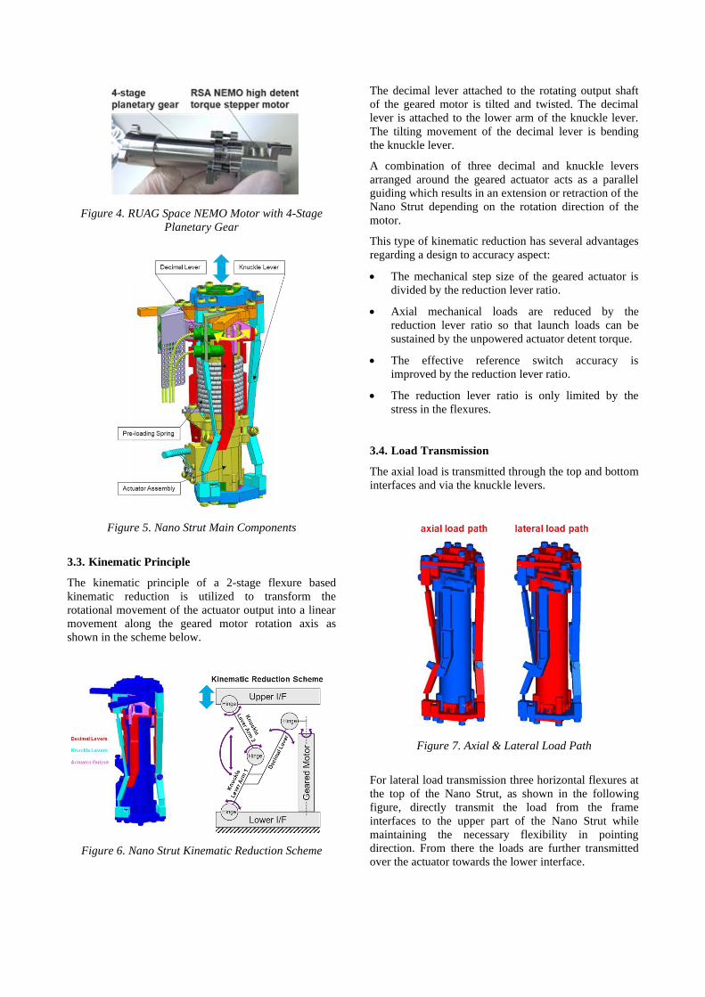
Figure 4. RUAG Space NEMO Motor with 4-Stage
Planetary Gear
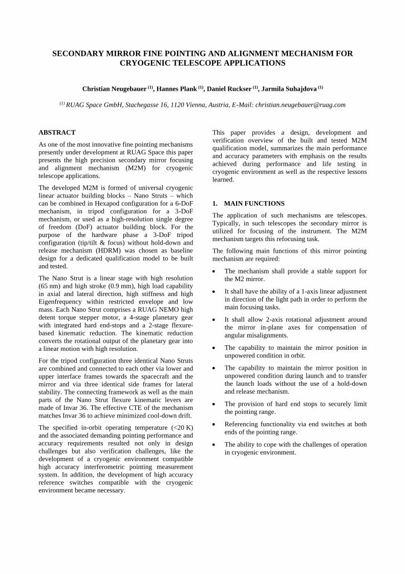
Figure 5. Nano Strut Main Components
3.3. Kinematic Principle
The kinematic principle of a 2-stage flexure based
kinematic reduction is utilized to transform the
rotational movement of the actuator output into a linear
movement along the geared motor rotation axis as
shown in the scheme below.
Figure 6. Nano Strut Kinematic Reduction Scheme
The decimal lever attached to the rotating output shaft
of the geared motor is tilted and twisted. The decimal
lever is attached to the lower arm of the knuckle lever.
The tilting movement of the decimal lever is bending
the knuckle lever.
A combination of three decimal and knuckle levers
arranged around the geared actuator acts as a parallel
guiding which results in an extension or retraction of the
Nano Strut depending on the rotation direction of the
motor.
This type of kinematic reduction has several advantages
regarding a design to accuracy aspect:
• The mechanical step size of the geared actuator is
divided by the reduction lever ratio.
• Axial mechanical loads are reduced by the
reduction lever ratio so that launch loads can be
sustained by the unpowered actuator detent torque.
• The effective reference switch accuracy is
improved by the reduction lever ratio.
• The reduction lever ratio is only limited by the
stress in the flexures.
3.4. Load Transmission
The axial load is transmitted through the top and bottom
interfaces and via the knuckle levers.
Figure 7. Axial & Lateral Load Path
For lateral load transmission three horizontal flexures at
the top of the Nano Strut, as shown in the following
figure, directly transmit the load from the frame
interfaces to the upper part of the Nano Strut while
maintaining the necessary flexibility in pointing
direction. From there the loads are further transmitted
over the actuator towards the lower interface.
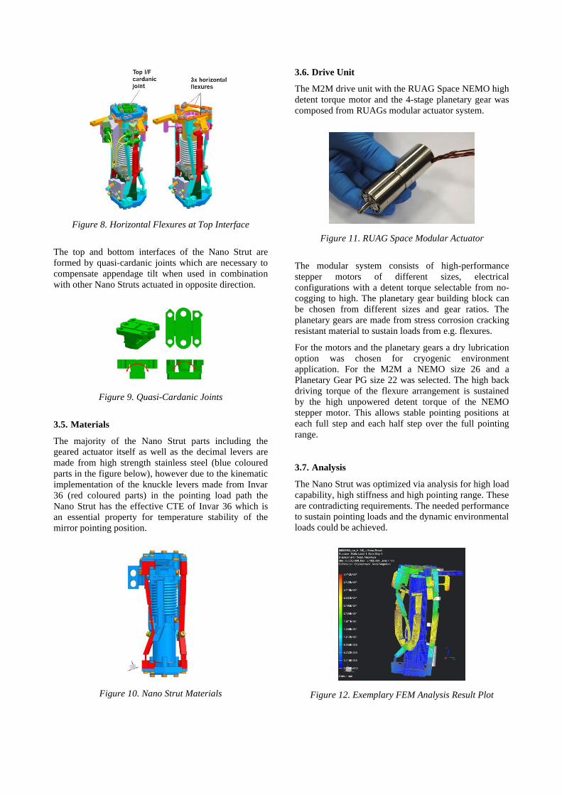
Figure 8. Horizontal Flexures at Top Interface
The top and bottom interfaces of the Nano Strut are
formed by quasi-cardanic joints which are necessary to
compensate appendage tilt when used in combination
with other Nano Struts actuated in opposite direction.
Figure 9. Quasi-Cardanic Joints
3.5. Materials
The majority of the Nano Strut parts including the
geared actuator itself as well as the decimal levers are
made from high strength stainless steel (blue coloured
parts in the figure below), however due to the kinematic
implementation of the knuckle levers made from Invar
36 (red coloured parts) in the pointing load path the
Nano Strut has the effective CTE of Invar 36 which is
an essential property for temperature stability of the
mirror pointing position.
Figure 10. Nano Strut Materials
3.6. Drive Unit
The M2M drive unit with the RUAG Space NEMO high
detent torque motor and the 4-stage planetary gear was
composed from RUAGs modular actuator system.
Figure 11. RUAG Space Modular Actuator
The modular system consists of high-performance
stepper motors of different sizes, electrical
configurations with a detent torque selectable from no-
cogging to high. The planetary gear building block can
be chosen from different sizes and gear ratios. The
planetary gears are made from stress corrosion cracking
resistant material to sustain loads from e.g. flexures.
For the motors and the planetary gears a dry lubrication
option was chosen for cryogenic environment
application. For the M2M a NEMO size 26 and a
Planetary Gear PG size 22 was selected. The high back
driving torque of the flexure arrangement is sustained
by the high unpowered detent torque of the NEMO
stepper motor. This allows stable pointing positions at
each full step and each half step over the full pointing
range.
3.7. Analysis
The Nano Strut was optimized via analysis for high load
capability, high stiffness and high pointing range. These
are contradicting requirements. The needed performance
to sustain pointing loads and the dynamic environmental
loads could be achieved.
Figure 12. Exemplary FEM Analysis Result Plot

The Nano Strut was sized to the following parameters:
• Axial stiffness: 4.78 N/µm
• Axial load capability: 1400 N
• Lateral load capability: 850 N
4. MODULARITY
With the Nano Strut building block, the envisaged
modularity could be achieved. It is possible to utilize the
same Nano Strut for single axis focusing concepts as
well as more complex tripod or hexapod configurations
enabling mirror alignment in 3 or 6 degrees of freedom.
Figure 13. Single Axis, Tripod (3-DoF) & Hexapod
(6-DoF) Configurations
Analyses have been performed for all variants whereas
the sweet spot for the market demand was found within
the tripod configuration which therefore was selected
for the hardware phase of the M2M.
4.1. Hexapod Assembly
The Hexapod configuration consists of 6 identical Nano
Struts which are connected via a lower and upper
interface frame towards the M2 mirror and the
spacecraft. The interface frames as well as the main
parts of the Nano Strut pointing load path are made
from Invar 36 material as mentioned before. Thus, the
effective CTE of the mechanism matches that of Invar
36 to achieve minimized cool-down drift.
A full analysis of the M2M in Hexapod configuration
has been carried out. The performance was confirmed
by analysis results. No hold down is needed due to the
sufficiently stiff Hexapod arrangement with a first
eigenfrequency of 110 Hz.
4.2. M2M Tripod Qualification Model
The developed M2M tripod qualification model consists
of 3 identical Nano Struts which are arranged in an
equilateral triangle and with their actuator rotation axes
aligned parallel to each other. The Nano Struts are
connected to each other via the lower and upper
interface frames towards M2 mirror and spacecraft
interface and 3 identical side frames for lateral stability
of the tripod. Also, in this configuration the framework
as well as the main parts of the Nano Strut pointing load
path are made from Invar 36 material to achieve the
effective CTE of Invar 36 for high temperature stability.
Figure 14. M2M Tripod Qualification Model

A full analysis has been performed for the M2M in
tripod configuration. The performance was confirmed
by analysis results. No hold down is needed due to the
sufficiently stiff Tripod arrangement with a first
eigenfrequency of 132 Hz.
5. QUALIFICATION CAMPAIGN
A full qualification test campaign has been performed
and successfully completed with all functional and
performance testing carried out in vacuum for MoS2
preservation.
The comprehensive test campaign started with initial
workmanship testing on motor, geared motor and Nano
Strut level. On M2M level standard physical properties
and electrical characterization testing was carried out
followed by the begin of life functional and
performance testing at room temperature in vacuum.
After the necessary sine, random and shock testing as
well as a TV cycling test, the performance and life test
in cryogenic environment was conducted.
Figure 15. M2M Tripod Qualification Test Flow
5.1. Performance and Accuracy Verification
For the purpose of the performance and accuracy
verification RUAG has developed an automated and
remotely controllable M2M Tripod control EGSE and
data acquisition system as well as a cryogenic
environment compatible high accuracy interferometric
pointing measurement system which allowed
continuous 6-degree of freedom measurement of the
mirror dummy pointing motion with nanometer
accuracy.
These systems were used during performance and
accuracy verification stages in vacuum at room
temperature but also during performance and life testing
in cryogenic environment. The ability to remotely
control pointing and acquisition proved to be very
beneficial due to Covid19 restrictions in place at the
time of the cryo test slot.
5.2. Vibration and Shock Testing
Vibration and shock testing have been successfully
performed with the M2M Tripod Qualification Model in
the specified worst-case launch pointing position. The
measured results were in line with the prediction. The
picture is giving some impressions of the vibration test
setup with the M2M Tripod on its vibration test adapter
and attached mirror mass dummy.
Figure 16. Vibration Test In-Plane Configuration
In the course of the vibration testing the shown random
input spectra for in- and out-of-plane excitation were
applied for 120 seconds at full level, resulting to 6.4 grms
for in-plane and about 10 grms in out-of-plane excitation.
Respective notches, as visualized in the plot below,
were agreed and applied to reduce accelerations and
stresses in the structure.
Axial Qualification Notched (OOP)
Frequency
[Hz]
ASD
[g2/Hz]dB #OCT dB / #OCT AREA grms
20 0.0142 - - - - -
100 0.3500 13.92 2.32 6.0 11.61 3.41
200 0.3500 0.00 1.00 0.0 46.61 6.83
280 0.1790 -2.91 0.49 -6.0 66.63 8.16
285 0.0036 -16.97 0.03 -664.4 66.85 8.18
365 0.0036 0.00 0.36 0.0 67.14 8.19
370 0.1040 14.61 0.02 744.2 67.29 8.20
2000 0.0036 -14.61 2.43 -6.0 98.78 9.94
Lateral Qualification Notched (IP)
Frequency
[Hz]
ASD
[g2/Hz]dB #OCT dB / #OCT AREA grms
20 0.0022 - - - - -
100 0.0550 13.98 2.32 6.0 1.82 1.35
115 0.0550 0.00 0.20 0.0 2.64 1.63
120 0.0150 -5.64 0.06 -91.9 2.80 1.67
130 0.0150 0.00 0.12 0.0 2.95 1.72
135 0.0550 5.64 0.05 103.6 3.10 1.76
270 0.0550 0.00 1.00 0.0 10.53 3.24
280 0.0150 -5.64 0.05 -107.5 10.83 3.29
350 0.0150 0.00 0.32 0.0 11.88 3.45
360 0.0550 5.64 0.04 138.8 12.19 3.49
500 0.0550 0.00 0.47 0.0 19.89 4.46
2000 0.0035 -12.00 2.00 -6.0 40.59 6.37
0.0001
0.0010
0.0100
0.1000
1.0000
10.0000
20 200 2000
ASD
[g2
/Hz]
Frequency [Hz]
Axial Qualification Notched (OOP) Lateral Qualification Notched (IP)
Figure 17. Notched Random Input

5.3. Thermal Cycling
Three thermal vacuum cycles as specified between
300 K and 100 K were performed with initial and final
functional tests carried out as well as function and
performance tests at the respective temperature
extremes.
1st cycle 2nd cycle
Ambient
3rd cycle
T [°C]
t [hrs]
Hot / 300K
Cold / 100K
Figure 18. Thermal Cycling Scheme
5.4. Performance and Life Testing in Cryogenic
Environment
The most challenging test during the whole qualification
campaign, was the performance and life testing in
cryogenic environment. Life testing as well as the
respective pre- and post-life performance testing was
carried out at below 20 K on all mechanism sensors.
Overall 180 full stroke and 1260 small stroke movement
cycles were performed to cover the specified on-ground
and in-orbit cycles with the M2M qualification model
showing no degradation of the pointing performance
and accuracy between pre- and post-life in cryogenic
environment and compared to begin-of-life results at
room temperature.
Ambient
T [°C]
t [hrs]
Cryo / K Life Cycling
Pointing Performance
Test
Pointing Performance
Test
Figure 19. Cryogenic Environment Testing Scheme
5.5. Resolution Measurement
The following plot depicts a typical resolution
measurement result acquired during piston pointing via
the interferometric measurement system. The plot
shows an actual piston displacement measurement
continuously recorded over time through which a
typical saw tooth profile over ±20 motor half steps was
commanded. The vertical axis of this plot shows the
linear displacement of the mirror interface, unit is µm. It
is visible that the mechanism makes clean steps with a
step size of 65 nm, so 0.065 µm step resolution. It shall
be noted that these steps are stable steps which the
mechanism is able to hold also in unpowered condition.
Figure 20. Exemplary Piston Pointing Step Resolution
Measurement
5.6. Pointing Space Exploration
In the Tripod configuration piston movement and
rotation around X and Y is possible. The movement of
the mirror is composed of the coupled three Nano Strut
positions.
Figure 21. Coupled Pointing & Piston Movement in Z
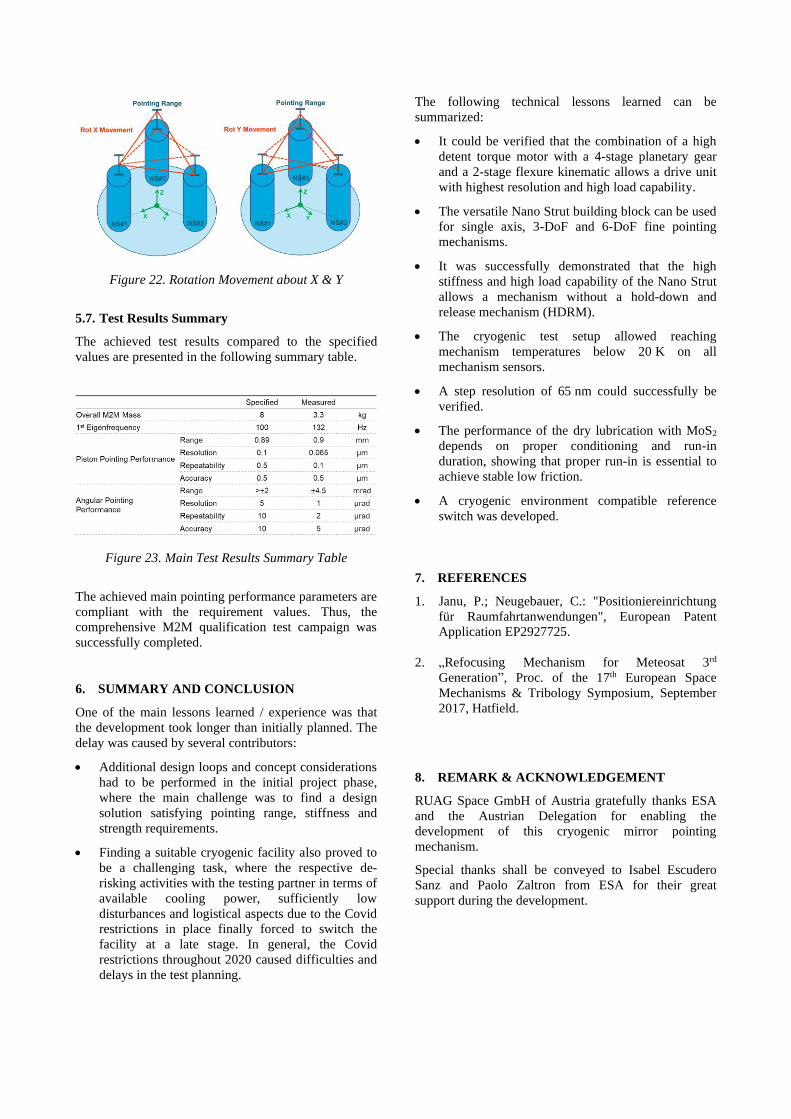
Figure 22. Rotation Movement about X & Y
5.7. Test Results Summary
The achieved test results compared to the specified
values are presented in the following summary table.
Figure 23. Main Test Results Summary Table
The achieved main pointing performance parameters are
compliant with the requirement values. Thus, the
comprehensive M2M qualification test campaign was
successfully completed.
6. SUMMARY AND CONCLUSION
One of the main lessons learned / experience was that
the development took longer than initially planned. The
delay was caused by several contributors:
• Additional design loops and concept considerations
had to be performed in the initial project phase,
where the main challenge was to find a design
solution satisfying pointing range, stiffness and
strength requirements.
• Finding a suitable cryogenic facility also proved to
be a challenging task, where the respective de-
risking activities with the testing partner in terms of
available cooling power, sufficiently low
disturbances and logistical aspects due to the Covid
restrictions in place finally forced to switch the
facility at a late stage. In general, the Covid
restrictions throughout 2020 caused difficulties and
delays in the test planning.
The following technical lessons learned can be
summarized:
• It could be verified that the combination of a high
detent torque motor with a 4-stage planetary gear
and a 2-stage flexure kinematic allows a drive unit
with highest resolution and high load capability.
• The versatile Nano Strut building block can be used
for single axis, 3-DoF and 6-DoF fine pointing
mechanisms.
• It was successfully demonstrated that the high
stiffness and high load capability of the Nano Strut
allows a mechanism without a hold-down and
release mechanism (HDRM).
• The cryogenic test setup allowed reaching
mechanism temperatures below 20 K on all
mechanism sensors.
• A step resolution of 65 nm could successfully be
verified.
• The performance of the dry lubrication with MoS2
depends on proper conditioning and run-in
duration, showing that proper run-in is essential to
achieve stable low friction.
• A cryogenic environment compatible reference
switch was developed.
7. REFERENCES
1. Janu, P.; Neugebauer, C.: "Positioniereinrichtung
für Raumfahrtanwendungen", European Patent
Application EP2927725.
2. „Refocusing Mechanism for Meteosat 3rd
Generation”, Proc. of the 17th European Space
Mechanisms & Tribology Symposium, September
2017, Hatfield.
8. REMARK & ACKNOWLEDGEMENT
RUAG Space GmbH of Austria gratefully thanks ESA
and the Austrian Delegation for enabling the
development of this cryogenic mirror pointing
mechanism.
Special thanks shall be conveyed to Isabel Escudero
Sanz and Paolo Zaltron from ESA for their great
support during the development.


![Monongalia mirror (Morgantown, Va. [W. Va.]).(Morgantown, Va. … · 2017-12-17 · to themovementsofthe moon, answerin.; to the tides of the ocean, and pointing its apex to that](https://img.pdfslide.us/doc/110x75/5e7e19c33bf39b5134340645/monongalia-mirror-morgantown-va-w-vamorgantown-va-2017-12-17-to-themovementsofthe.jpg)