Embed Size (px)
DESCRIPTION
SECCHI 3D Reconstruction Efforts at NRL. Angelos Vourlidas Naval Research Laboratory. With inputs from: R. Howard, J. Newmark, J. Cook, P. Reiser. Outline. Currently pursuing three approaches for 3D reconstructions of CMEs and coronal structures (plumes, streamers, etc). - PowerPoint PPT Presentation
Citation preview

SECCHI 3D Reconstruction Efforts at NRL
Angelos VourlidasNaval Research Laboratory
With inputs from:R. Howard, J. Newmark, J. Cook, P. Reiser

STEREO SWG, Hamburg May 2005 Angelos Vourlidas, NRL
Outline
• Currently pursuing three approaches for 3D reconstructions of CMEs and coronal structures (plumes, streamers, etc).
– Parametric modeling (RayTrace)
Thernisien, Howard
– Tomographic modeling (Pixon)
Cook, Newmark, Reiser
– Hybrid Approach (Pixon w/ ARM)
Reiser
STEREO SWG, Hamburg May 2005 Angelos Vourlidas, NRL
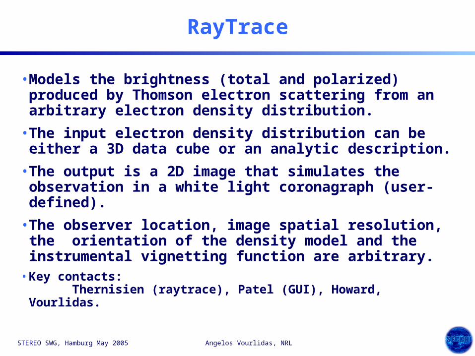
RayTrace
• Models the brightness (total and polarized) produced by Thomson electron scattering from an arbitrary electron density distribution.
• The input electron density distribution can be either a 3D data cube or an analytic description.
• The output is a 2D image that simulates the observation in a white light coronagraph (user-defined).
• The observer location, image spatial resolution, the orientation of the density model and the instrumental vignetting function are arbitrary.
• Key contacts: Thernisien (raytrace), Patel (GUI), Howard, Vourlidas.

STEREO SWG, Hamburg May 2005 Angelos Vourlidas, NRL
RayTrace Frontend
From Thernisien et al. 2004

STEREO SWG, Hamburg May 2005 Angelos Vourlidas, NRL
RayTrace Visualization
• Example of a fluxrope visualization in RayTrace.
From Thernisien et al. 2004
STEREO SWG, Hamburg May 2005 Angelos Vourlidas, NRL
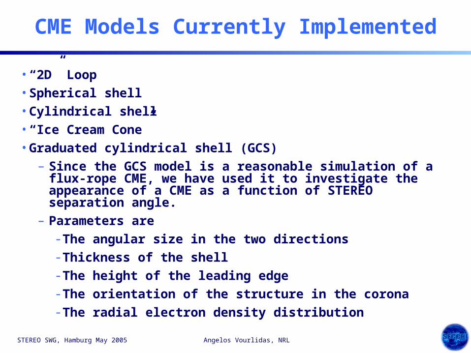
CME Models Currently Implemented
• “2D” Loop
• Spherical shell
• Cylindrical shell
• “Ice Cream Cone”
• Graduated cylindrical shell (GCS)
– Since the GCS model is a reasonable simulation of a flux-rope CME, we have used it to investigate the appearance of a CME as a function of STEREO separation angle.
– Parameters are
- The angular size in the two directions
- Thickness of the shell
- The height of the leading edge
- The orientation of the structure in the corona
- The radial electron density distribution

STEREO SWG, Hamburg May 2005 Angelos Vourlidas, NRL
Spherical Shell

STEREO SWG, Hamburg May 2005 Angelos Vourlidas, NRL
“Flux Rope” Calculated in 3 Orientations

STEREO SWG, Hamburg May 2005 Angelos Vourlidas, NRL
“Horizontal” Flux Rope
• We present views of the horizontal flux rope as a function of angle from the observer’s viewpoint
– A halo CME is 0 degrees
– A limb CME is 90 degrees
• The SECCHI COR2 vignetting function as been applied

STEREO SWG, Hamburg May 2005 Angelos Vourlidas, NRL
Horizontal “Flux Rope”

STEREO SWG, Hamburg May 2005 Angelos Vourlidas, NRL
RayTrace Summary
• We have simulated the effect of the STEREO orbit separation on the appearance and the ability to reconstruct the 3D geometry
• Spherical Shell, Loop, Cone and Graduated Cylinder give recognizable differences
• Stereo separation angles of <20 degrees show little to no stereo effect.
• Polarized Brightness (pB) images have little effect on CMEs at the limb, but considerable effect at large angles from the plane of the sky.
• Complementary to 3D inversion and MHD techniques.
• Could provide constraints to the MHD models.

STEREO SWG, Hamburg May 2005 Angelos Vourlidas, NRL
Tomographic Modeling
• Strategy:
– Apply 3D tomographic electron density reconstruction techniques to solar features (mainly CMEs).
– Utilize B, pB, temporal evolution from 2/3 vantage points.
– Construct (time dependent) 3D electron density distribution.
• Focus:
– Use theoretical CME models and existing LASCO observations to identify the range of conditions and features where reconstruction techniques will be applicable.
• Goal:
– Provide a practical tool that will achieve ~daily CME 3D electron density models during the STEREO mission.
• Key contacts:
– J. Newmark, J. Cook, P. Reiser

STEREO SWG, Hamburg May 2005 Angelos Vourlidas, NRL
Key Aspects
• Renderer:
– Physics (Thomson scattering), tangential and radial pB, total B, finite viewer geometry, optically thin plasma.
• Reconstruction Algorithm:
– PIXON (Pixon LLC), Pina, Puetter, Yahil (1993, 1995) - non-parametric, locally adaptive, iterative image reconstruction.
– Chosen for speed (<10^9 voxels): small number of iterations, intelligent guidance to declining complexity per iteration. Sample times: 323 <15 min, 643 ~1 hr, 1283 ~6 hrs (1 GHz PC).
– Minimum complexity: With this underdetermined problem, we make minimal assumptions in order to progress. Another possibility is forward modeling
• Visualization:
– 3D electron density distribution, time dependent (movies), multiple instrument, multiple spacecraft, physics MHD models.

STEREO SWG, Hamburg May 2005 Angelos Vourlidas, NRL
3D Reconstruction: CME model (J. Chen)Three Orthogonal Viewpoints

STEREO SWG, Hamburg May 2005 Angelos Vourlidas, NRL
3D Reconstruction: CME model (J. Chen)Three Ecliptic Viewpoints

STEREO SWG, Hamburg May 2005 Angelos Vourlidas, NRL
3D Reconstruction: CME model (J. Chen)Two Viewpoints
STEREO SWG, Hamburg May 2005 Angelos Vourlidas, NRL
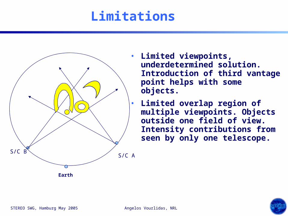
Limitations
• Limited viewpoints, underdetermined solution. Introduction of third vantage point helps with some objects.
• Limited overlap region of multiple viewpoints. Objects outside one field of view. Intensity contributions from seen by only one telescope.
S/C A S/C B
Earth

STEREO SWG, Hamburg May 2005 Angelos Vourlidas, NRL
Hybrid (ARM) Modeling
• Recently we started exploring a 3rd approach to electron density reconstruction.
– Namely, to incorporate a priori knowledge to the tomograhic method (Additional Regularization Method (ARM) ).
– For example, we “know”
- that electrons should be distributed smoothly along LOS,
- that the emission should be positive,
- that the large scale envelope of the CME should be symmetric.
• Paul Reiser tested the effect of several constraints on synthetic data

STEREO SWG, Hamburg May 2005 Angelos Vourlidas, NRL
A Priori Knowledge
1. Electron Density Distribution is Smooth
2. Axial Symmetry
But• Problem is underdetermined (2N2 equations, N3 unknowns)
• Solutions are noisy
Let’s add two constraints:

STEREO SWG, Hamburg May 2005 Angelos Vourlidas, NRL
Hybrid Modeling w/ Axial Symmetry

STEREO SWG, Hamburg May 2005 Angelos Vourlidas, NRL
Another Example - Unmatched Scenes
What to do when one viewpoint contains additional structure?

STEREO SWG, Hamburg May 2005 Angelos Vourlidas, NRL
Unmatched Scenes- ARM Result

STEREO SWG, Hamburg May 2005 Angelos Vourlidas, NRL
Conclusions
• Useful 3D reconstructions are achievable!
• Parametric modeling is easy to implement, fast, and intuitive. It can be directly linked to MHD models. Unlikely to match observations in detail.
• Tomographic techniques achieve better agreement with observations. Time-consuming, error analysis is difficult/complex.
• Incorporation of a priori knowledge in tomographic reconstruction shows great promise. Minimization subject to “magic” selection of parameters (different for each reconstruction). Still time-consuming
• Tomographic reconstructions are significantly improved with the addition of a third viewpoint (LASCO continuing operation is extremely important).
• Application to SECCHI will require substantial effort and collaboration; we appreciate all help on scientific preparations.
• Web Site: http://stereo.nrl.navy.mil/ (follow link to 3D R&V). This contains past presentations and all necessary details to test reconstruction methods on our sample problems.

STEREO SWG, Hamburg May 2005 Angelos Vourlidas, NRL
Backup

STEREO SWG, Hamburg May 2005 Angelos Vourlidas, NRL
Views From STEREO-A and -B

STEREO SWG, Hamburg May 2005 Angelos Vourlidas, NRL
SECCHI Telescopes
• The SECCHI suite consists of 5 telescopes to observe CMEs from their birth at the solar surface through the corona and into the inner heliosphere
Telescope EUVI COR1 COR2 HI-1 HI-2
FOV (Rsun) disk -1.7 1.3 - 4 2.5 - 15 12 - 85 66 - 318
Pixel Size (arcsec)
1.7 arc sec 1.3 - 8 2.5 - 15 70 243
Fe IX 17.1 nm White Light White Light White Light White Light
Fe XII 19.5 nm
Fe XV 28.4 nm
He II 30.4 nm
Bandpass

STEREO SWG, Hamburg May 2005 Angelos Vourlidas, NRL
Science - Examples
• Geometric figures - uniform density, no background
• Polar Plumes - hydrostatic equilibrium solution of density vs. height, tube expansion, statistics.
• Equatorial streamers - projection of current sheets, effect of AR’s, compare to 3D reconstruction using tie points (Liewer 2001), density enhancements vs. folds.
• CME’s – Use models to prepare for SECCHI, effect of viewpoint angles, velocity, polarization, structure evolution, etc. CME models include time dependence
– J. Chen – CME, no background
– P. Liewer – CME + background – not yet studied
– Z. Mikic – CME, K corona evolution
– S.T. Wu – CME - not yet studied
• Questions: How to isolate CME? Assume subtraction of F+minimum K corona, but how to handle time dependent K corona? Why we want to: decrease complexity, eliminate structures of equal or greater brightness

STEREO SWG, Hamburg May 2005 Angelos Vourlidas, NRL
3-D Reconstruction Using the Pixon Method
• The problem is to invert the integral equation with noise:
• But there are many more model voxels than data pixels.• And the reconstruction significantly amplifies the noise.• All reconstruction methods try to overcome these problems by restricting the
model; they differ in how they do that.• A good first restriction is non-negative n(r).
Non-Negative Least-Squares (NNLS) fit.• Minimum complexity (Ockham’s razor): restrict n(r) by minimizing the number of
parameters used to define it.• The number of possible parameter combinations is large.
An exhaustive parameter search is not possible.• The Pixon method is an efficient iterative procedure that approximates minimum
complexity by finding the smoothest solution that fits the data (details: Puetter and Yahil 1999).
• New modification: Adaptive (Hierarchical) Gridding
)()(),()( 3 xrrxrdx nnn NnHD

STEREO SWG, Hamburg May 2005 Angelos Vourlidas, NRL
“Flux Rope” Calculated in Total B and pB
pBB
STEREO SWG, Hamburg May 2005 Angelos Vourlidas, NRL
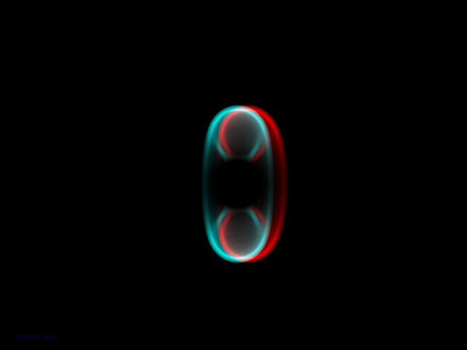
Evolution of Vertical “Flux Rope”
as a Halo

STEREO SWG, Hamburg May 2005 Angelos Vourlidas, NRL

STEREO SWG, Hamburg May 2005 Angelos Vourlidas, NRL

STEREO SWG, Hamburg May 2005 Angelos Vourlidas, NRL

STEREO SWG, Hamburg May 2005 Angelos Vourlidas, NRL

STEREO SWG, Hamburg May 2005 Angelos Vourlidas, NRL

STEREO SWG, Hamburg May 2005 Angelos Vourlidas, NRL

STEREO SWG, Hamburg May 2005 Angelos Vourlidas, NRL

STEREO SWG, Hamburg May 2005 Angelos Vourlidas, NRL

STEREO SWG, Hamburg May 2005 Angelos Vourlidas, NRL

STEREO SWG, Hamburg May 2005 Angelos Vourlidas, NRL
STEREO SWG, Hamburg May 2005 Angelos Vourlidas, NRL

STEREO SWG, Hamburg May 2005 Angelos Vourlidas, NRL

STEREO SWG, Hamburg May 2005 Angelos Vourlidas, NRL