Embed Size (px)
Citation preview

Pile Driveability and Installation
Seaway Heavy Lifting Engineering B.V.Albert Einsteinlaan 502719 ER ZoetermeerThe Netherlands
Tel: +31 (0)79 363 77 00Fax: +31 (0)79 363 77 99Email: [email protected]
www.shl.nl
3
Contents
Introduction and Conclusions 4
Soil Investigation 7
Platform Foundation Piles 13
Followers 16
Pile-Driving Hammers 18
Pile Make-Up and Driveability 22
Aspects of Premature Refusals 28
Pile Monitoring 30
Cost Savings of a Proper Pile Design 33
Acknowledgements 42

4 5
• Installation contractors are focused on an optimum vessel schedule with the lowest
uncertainty about durations. Hence, the installation contractor requires a pile design
that allows the use of a larger hammer in case of heavy driving. This approach
reduces the chance for remedial work caused by pile refusal.
Pile refusal is an unacceptable risk for an installation contractor as it could double
or triple the overall installation duration and these unanticipated delays (due to
remedial work), cause disruption to their schedule and may well affect subsequent
projects. An installation contractor’s bid will reflect this potential commercial impact.
Therefore, the installation contractor always puts great effort into analysing the
driveability of the piles.
In the section “Pile Make-Up and Driveability” the effect of the pile wall thickness on its
driveability is explored further. The commercial implications for two different pile designs
are examined at the end of this booklet.
Key Features
• Proper pile design can save millions.
• Pile refusal is an unacceptable risk for installation contractors.
• Pile driveability analysis must be part of the platform foundation design.
• Pile wall thickness is of major importance to the pile’s driveability.
Introduction and Conclusions
Introductions
This booklet provides information about the installation of foundation piles for fixed
platforms. It is provided by Seaway Heavy Lifting Engineering (SHL), and it incorporates
the experience of SHL as a successful installation contractor for the oil and gas industry.
This booklet intends to provide additional information to come to a “total cost” approach
for platform foundation designs. From SHL experience, the pile installation aspects of a
platform are not always properly incorporated into the design. Typically, pile design
is based on ultimate axial and lateral capacity requirements only. Driveability of the piles,
which are of major importance to the economics of an overall platform installation, is
often not considered. With this booklet, SHL clarifies that investing in pile material can
have a very compelling money saving potential for the overall project.
Specific Interests of Parties Involved
Operators, EPIC contractors and installation contractors have different interests in
a platform design:
• The operator requires a sound platform at the lowest cost. The platform must last for
many years so that it can become a hub in the event of substantial finds in the same area.
• The EPIC contractor designs the platform at the lowest fabrication cost. These
contractors generally bid for the work in a very competitive market especially in case
of a design competition. The competitive process causes bidders to ignore the
installation aspects of the platform and the
piles, which may add to the material costs.
Soil mechanics is not an exact science and
soil properties are not always precisely
known. These factors often cause EPIC
contractors to select the lightest possible
pile design and by doing so, they jeop-
ardise pile driveability. These contractors
assume that the pile can be driven to an
acceptable penetration without requiring
remedial actions.
6 7
Soil Investigation
General
Site investigations are often in progress when budgets are restricted because the final
investment decision has not yet been made. There is always pressure to minimise costs
and therefore, also the scope of work. Furthermore, platform location may not yet be
certain. These factors, unfortunately, conflict with the future success of the project.
The extent of the soil investigation has significant implications on the cost of a project.
If only limited information is available to the engineering contractor, a conservative
approach with regards to the pile design is adopted with subsequent cost effects.
Since soil investigations are the first site works, the soils information may not yet be
available to the engineering contractor or EPIC contractor to optimize the foundation
design. This approach can lead to piled foundations that are often over-designed.
This “waste”, which is ultimately paid for by the operator, can be greatly reduced if
sufficient soils data is available before the pile design starts.
Furthermore, the cost and time overruns are attributable to inadequate information
about the soil conditions. It is important therefore, to strike the correct balance between
the cost of the soil investigation and its accuracy. Identification of the type of tests
performed, the required results and the correct borehole locations optimise the total
project cost.
Effective soil investigation has the purpose of risk and cost reduction. Hence, it is
important that these investigations have an accurate specification and direction.
Any soil investigation should be carried out by a specialised geotechnical company,
preferably under the supervision of an operator representative. At the proposed
platform location, typically one or two boreholes are drilled to a depth likely exceeding
the pile’s design penetration. At regular intervals, or when soil layer changes are
foreseen, soil samples are taken for laboratory tests.
Conclusions
• A good foundation design not only results in an efficient installation, but also it
reduces the overall cost of a platform.
• Premature refusal could cost millions of dollars exceeding the original price for the
platform installation itself. Therefore, to reduce this risk, a proper driveability study
during the design phase is required.
• Remedial work on the pile foundation could take weeks. This delay may jeopardise
the first production date of the platform and incur costs for remedial work.
• In a good pile design, the pile wall thickness must be sufficient to transfer the
hammer’s energy.
• An optimal pile design allows for a more powerful hammer to be stabbed when
harder than expected driving is encountered.
• Installation aspects, such as allowable freestanding pile lengths versus required
hammer energy, should be considered for the final pile make-up.
• The accuracy of a pile driveability study can be highly optimised by incorporating
other knowledge, such as performing back analyses using the observed blow counts
of the as-installed piles of a nearby platform.

8 9
This lack of information and this intolerance for risk of an inadequate pile design often
leads to over-designed (deeper) target penetration when hard driving is foreseen.
Ultimately, in the event of pile refusal, the operator runs a significant risk of budget
overrun and late platform delivery.
Soils Investigation and Pile Installation
Piled platforms are common worldwide. Offshore pile driving has been carried out
at numerous locations by many contractors, although not always with success.
Sometimes, premature refusal or too-easy driving to target penetration is encountered.
In both cases, the platform installation work stagnates. Installation can be resumed only
after the problem is resolved – initiate remedial activities or accept the situation. If
remedial action is required, which remedial action needs to be carried out? Whatever
action is chosen, the overall platform installation time takes longer and costs more than
expected. These additional costs can be very high, especially if specific equipment for a
remedial activity was not mobilised with the installation spread.
Therefore, it is important to establish the pile make-up, not only on the soil strength
reported and on the required design loads for the piles, but also incorporating the
installation aspects. The platform loads define a pile target penetration only. However, hard
layers might be evident between the seabed and the defined target penetration. In such
cases, premature refusal might occur in the hard layer. If the pile make-up is designed to
cope with that hard layer and the piles are matched with a properly selected pile-driving
hammer, then that premature refusal probably can be avoided.
Soils can be classified in different groups, with their own characteristics in relation to
pile ultimate static capacity. Likewise, soils can be characterized by their behaviour
during pile driving. A desk study to define the suitable hammer to drive the piles is
always needed to evaluate the most economical installation for the given situation.
The study avoids the requirement for too many add-ons and reduces beforehand
the risks related to premature refusal or drop falls (loss of hammer-pile contact,
damage to the crane) caused by a pile resistance that is too low.
The goal of these laboratory tests is to indicate the soil’s characteristics. A cone
penetration test (CPT) can be carried out in the hole and indicates the density of the
soil. A CPT generally consists of two measurements: tip resistance and shaft friction.
An electrical cone is pushed into the undisturbed strata at a preset speed. The cone
resistance is an indication of the in-situ density of the soil and the shaft friction is an
indication of the likely friction the soil can mobilise. Other kinds of special tests can also
be performed in the borehole. For example, a vane shear test and dissipation test can be
added. Where harder clays, higher density sands, or cemented materials are encountered
and if the CPT capacity is insufficient, coring is advised. With the soil sample, the soil engi-
neer can observe and determine the properties of the material. It is important to assess
the hardness or strength of the material, as well as the thickness of the layer.
When a soil investigation is performed and reported, pile axial and lateral ultimate
capacity computations are made. Piles are then designed as a foundation for the
proposed structure. If the soil investigation is
of poor quality, for example, if the investigation
has unreliable CPTs and is done without
proper sampling or coring, then lower limits
are applied for the ultimate static capacity
calculations. This application of lower limits
might result in an approach that is too
conservative and as such, the foundation is
over-designed, which is not economical.
For an effective installation, the installation contractor must know the upper boundary
strength of the soils. With this knowledge, the contractor can select the hammer that will
“certainly” drive the piles to their target penetration. Often this data is not available due
to a poor quality CPT or the lack of cores taken and tested, particularly in areas where
cemented soils, calcarenite, or gypsum are evident.

10 11
Soil Set Up
Due to pile driving, the soils will remould (fatigue) along the pile wall. After a pause
or stop in pile driving, the soil has a tendency to obtain its original strength again.
This phenomenon is called soil set up. Set up is dependant on the soil type: The set-up
factor in sands is relatively low, while the set-up factor in plastic clays is high. Therefore,
consider set up when planning the intermediate stops to reach target penetration.
Stops during pile driving are caused
by a hammer breakdown, bad
weather or scheduled stops to weld
add-ons. Planned stops should be
carefully scheduled for welding
add-ons. Do not schedule a stop
when the pile toe is at or in a hard
layer. In this case, not only will the pile
toe have to overcome the increased
frictional resistance due to set up, but
also it must overcome a higher pile tip
resistance to penetrate into a hard
layer at the same time. This combination can easily lead to premature refusal when
a change-over to a larger hammer cannot be initiated. The larger hammer may have
a restriction in relation to the pile-free length. Or, the hammer needed to overcome the
soil resistance may exceed the pile’s maximum allowable driving stress. Therefore,
a good driveability study must account for set up.
Shaft Friction and Tip Resistance
Soils that typically cause premature refusal are cemented layers, calcarenite, gypsum,
large boulders as well as very hard clays and very dense sands. Associated problems
are the depth at which these layers or boulders are found: near the seabed or at greater
depth. Regardless of where the hard layer is encountered, if low frictional resistance
occurs in the soft layers above, then practically all hammer energy can still be trans-
ferred to the pile toe to obtain tip displacement. However, if substantial frictional
resistance is already built up along the pile wall when the hard layer is reached, then
much of the hammer energy is needed to overcome the frictional resistance. In this
case, only a small portion of energy is available to achieve tip displacement into the
hard layer. Therefore, the risk of refusal is higher when the hard layer occurs at deeper
depth, especially in combination with a high friction resistance buildup.
In some soils, soft layers are present over intervals and low frictional soil resistance is
built up along the pile wall at that depth. Driving in these soils brings the risk that the
pile falls free after a single blow, even at a low energy setting of a hydraulic hammer.
In such a situation, the pile-hammer contact is lost and another blow might then
damage the crane. A similar situation could occur where the resistance is unexpectedly
low near target penetration. Too much energy in the hammer blows might force the pile
farther than the target penetration, i.e., the pile might be “lost” in the leg or sleeve.
Such situations are more common with a steam hammer than with a hydraulic hammer.
The reason is that the energy output in a hydraulic hammer can be fully controlled.
12 13
Platform Foundation Piles
General
To account for natural variations in soil conditions and soil behaviour, there could be
a preference to minimize the shear load on foundation piles, in particular when the top
soils are soft. Minimum shear loads are realised by inclining the piles. By doing so, the
piles are installed through the platform legs and the whole pile installation operation is
performed battered.
Skirt Piles
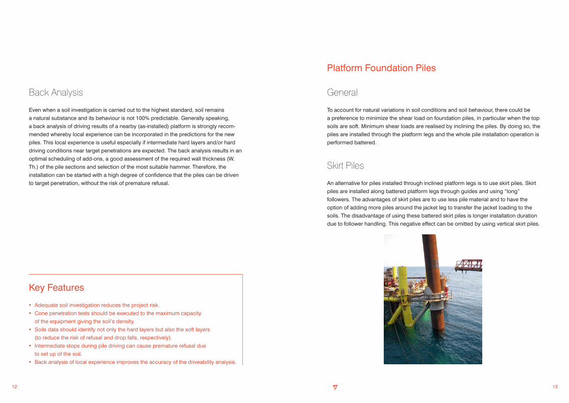
An alternative for piles installed through inclined platform legs is to use skirt piles. Skirt
piles are installed along battered platform legs through guides and using “long”
followers. The advantages of skirt piles are to use less pile material and to have the
option of adding more piles around the jacket leg to transfer the jacket loading to the
soils. The disadvantage of using these battered skirt piles is longer installation duration
due to follower handling. This negative effect can be omitted by using vertical skirt piles.
Back Analysis
Even when a soil investigation is carried out to the highest standard, soil remains
a natural substance and its behaviour is not 100% predictable. Generally speaking,
a back analysis of driving results of a nearby (as-installed) platform is strongly recom-
mended whereby local experience can be incorporated in the predictions for the new
piles. This local experience is useful especially if intermediate hard layers and/or hard
driving conditions near target penetrations are expected. The back analysis results in an
optimal scheduling of add-ons, a good assessment of the required wall thickness (W.
Th.) of the pile sections and selection of the most suitable hammer. Therefore, the
installation can be started with a high degree of confidence that the piles can be driven
to target penetration, without the risk of premature refusal.
Key Features
• Adequate soil investigation reduces the project risk.
• Cone penetration tests should be executed to the maximum capacity
of the equipment giving the soil’s density.
• Soils data should identify not only the hard layers but also the soft layers
(to reduce the risk of refusal and drop falls, respectively).
• Intermediate stops during pile driving can cause premature refusal due
to set up of the soil.
• Back analysis of local experience improves the accuracy of the driveability analysis.

14 15
• A vertical skirt pile is typically installed in one section. This pile configuration is
possible since allowable freestanding pile lengths are much longer for vertical skirt
piles than for inclined piles.The hydraulic hammer can be regulated at a low energy
setting at the start of driving. Gradually, the energy setting can be increased in
accordance with soil resistance met during driving (SRD). Therefore, often only one
piling hammer is needed for the installation.
• Consequently, no driving stops for stabbing and splicing of add-ons are required.
Thus, fast installation and less risk of premature refusal are realised.
• During installation, the loading on the jacket’s mud mats is substantially less when
vertical skirt piles are used than for a main pile. When a very soft seabed is evident,
vertical skirt piles also reduce the installation risk of additional levelling upon
completion of the piling operation.
• Skirt pile installation is faster than main pile installation because fewer pile sections
are used.
• Vertical skirt pile can accommodate hydraulic hammers directly in contrast to inclined
skirt piles, which require followers.
• The jacket is secured faster with vertical skirt piles than with inclined skirt piles or
main piles.
Vertical Skirt Piles
The most economical solution is to drive
vertical skirt piles. The hydraulic hammer
drives directly on top of the skirt pile or is
used in combination with a “short” front
follower. The driveability of vertical skirt
piles is of crucial importance. If the pile
meets refusal, it must be drilled out. The
drilling assembly must be operated above
water at a relatively large distance from the
jacket top elevation and the assembly
requires a special outrigger. Therefore, a
vertical skirt pile is recommended only if
the driveability of the piles is verified properly
and the risk of premature refusal is negligible.
For vertical skirt piles combined with soft top soils, a thicker W.Th. is required for the pile
section near seabed. This added thickness is needed because the shear loads in this
case are not transferred as per battered piles. Vertical skirt piles have the following
advantages:
• The total installed pile length is much shorter than a pile installed through a jacket
leg, saving significant pile material.
• If a front follower is used, then the pile head can be driven almost flush with the top
of the pile sleeve, again saving pile material. In this context, it must be noted that the
required front follower is costly and only favourable if a series of skirt piles are to be
installed.

16 17
Flying Follower
A flying follower is a follower extending the generally inclined pile above its support.
A flying follower is typically applied when the top of a main or skirt pile is to be driven
through the top of the leg or through a top guide. Depending on the hammer sched-
uled, follower length and pile batter, severe bending moments may occur in the gravity
connector of the follower. For that purpose, these followers are equipped with a moment
resistant gravity connector.
Long Follower, Supported by Vessel
A long follower is used for the installation of
a freestanding anchor pile with the follower supported
against the installation vessel. The pile can be kept
upright and installed within vertical tolerances.
Depending on the hammer selected, follower stiffness,
pile stiffness and the water depth, the gravity connector
can encounter a high bending moment.
Front Follower
A front follower is typically used in combination with a hydraulic hammer to drive the
piles flush with the template or jacket skirt pile sleeve. Front followers are usually short
and the piles to be driven with them are usually vertical. Thus, bending moments in the
gravity connector of a front follower are small.
Followers
General
Followers are used for the installation of piles when driving directly on top of the pile is not
possible or not preferred. The stabbing point of a follower may be subjected to severe
acceleration forces. External forces acting on the gravity connector are caused by:
• Pile inclination
• Jacket out of level
• Rotation due to clearance in guides
• Rotation due to clearance in the gravity connector
• Bending of the pile or follower string, including second-order effects caused
by dead loads, hammer weight, wind, waves, current and vessel excursion
Driving heads for followers are subject
to the same design rules as piles.
Follower attachments must be
designed for acceleration forces.
Vent holes are required in a front
follower when driving directly on a pile
under water. A vent hole discharges a
volume of water equal to the reduction
of the volume inside the pile under the
fastest progress during driving. Drill
vent holes carefully to prevent cracks
during pile driving.
The effect of the use of a follower in
relation to energy transfer from the top
of the follower to the top of the pile is
typically a loss of approximately 10%.
18 19
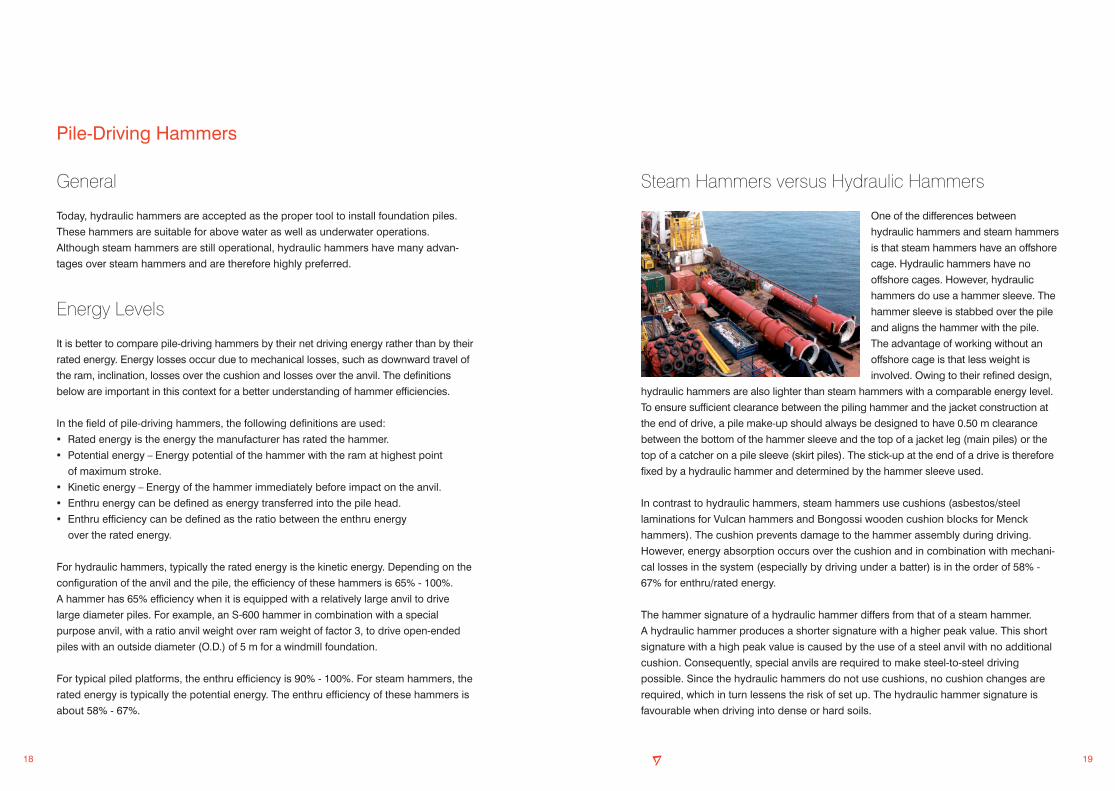
Steam Hammers versus Hydraulic Hammers
One of the differences between
hydraulic hammers and steam hammers
is that steam hammers have an offshore
cage. Hydraulic hammers have no
offshore cages. However, hydraulic
hammers do use a hammer sleeve. The
hammer sleeve is stabbed over the pile
and aligns the hammer with the pile.
The advantage of working without an
offshore cage is that less weight is
involved. Owing to their refined design,
hydraulic hammers are also lighter than steam hammers with a comparable energy level.
To ensure sufficient clearance between the piling hammer and the jacket construction at
the end of drive, a pile make-up should always be designed to have 0.50 m clearance
between the bottom of the hammer sleeve and the top of a jacket leg (main piles) or the
top of a catcher on a pile sleeve (skirt piles). The stick-up at the end of a drive is therefore
fixed by a hydraulic hammer and determined by the hammer sleeve used.
In contrast to hydraulic hammers, steam hammers use cushions (asbestos/steel
laminations for Vulcan hammers and Bongossi wooden cushion blocks for Menck
hammers). The cushion prevents damage to the hammer assembly during driving.
However, energy absorption occurs over the cushion and in combination with mechani-
cal losses in the system (especially by driving under a batter) is in the order of 58% -
67% for enthru/rated energy.
The hammer signature of a hydraulic hammer differs from that of a steam hammer.
A hydraulic hammer produces a shorter signature with a higher peak value. This short
signature with a high peak value is caused by the use of a steel anvil with no additional
cushion. Consequently, special anvils are required to make steel-to-steel driving
possible. Since the hydraulic hammers do not use cushions, no cushion changes are
required, which in turn lessens the risk of set up. The hydraulic hammer signature is
favourable when driving into dense or hard soils.
Pile-Driving Hammers
General
Today, hydraulic hammers are accepted as the proper tool to install foundation piles.
These hammers are suitable for above water as well as underwater operations.
Although steam hammers are still operational, hydraulic hammers have many advan-
tages over steam hammers and are therefore highly preferred.
Energy Levels
It is better to compare pile-driving hammers by their net driving energy rather than by their
rated energy. Energy losses occur due to mechanical losses, such as downward travel of
the ram, inclination, losses over the cushion and losses over the anvil. The definitions
below are important in this context for a better understanding of hammer efficiencies.
In the field of pile-driving hammers, the following definitions are used:
• Rated energy is the energy the manufacturer has rated the hammer.
• Potential energy – Energy potential of the hammer with the ram at highest point
of maximum stroke.
• Kinetic energy – Energy of the hammer immediately before impact on the anvil.
• Enthru energy can be defined as energy transferred into the pile head.
• Enthru efficiency can be defined as the ratio between the enthru energy
over the rated energy.
For hydraulic hammers, typically the rated energy is the kinetic energy. Depending on the
configuration of the anvil and the pile, the efficiency of these hammers is 65% - 100%.
A hammer has 65% efficiency when it is equipped with a relatively large anvil to drive
large diameter piles. For example, an S-600 hammer in combination with a special
purpose anvil, with a ratio anvil weight over ram weight of factor 3, to drive open-ended
piles with an outside diameter (O.D.) of 5 m for a windmill foundation.
For typical piled platforms, the enthru efficiency is 90% - 100%. For steam hammers, the
rated energy is typically the potential energy. The enthru efficiency of these hammers is
about 58% - 67%.
20 21
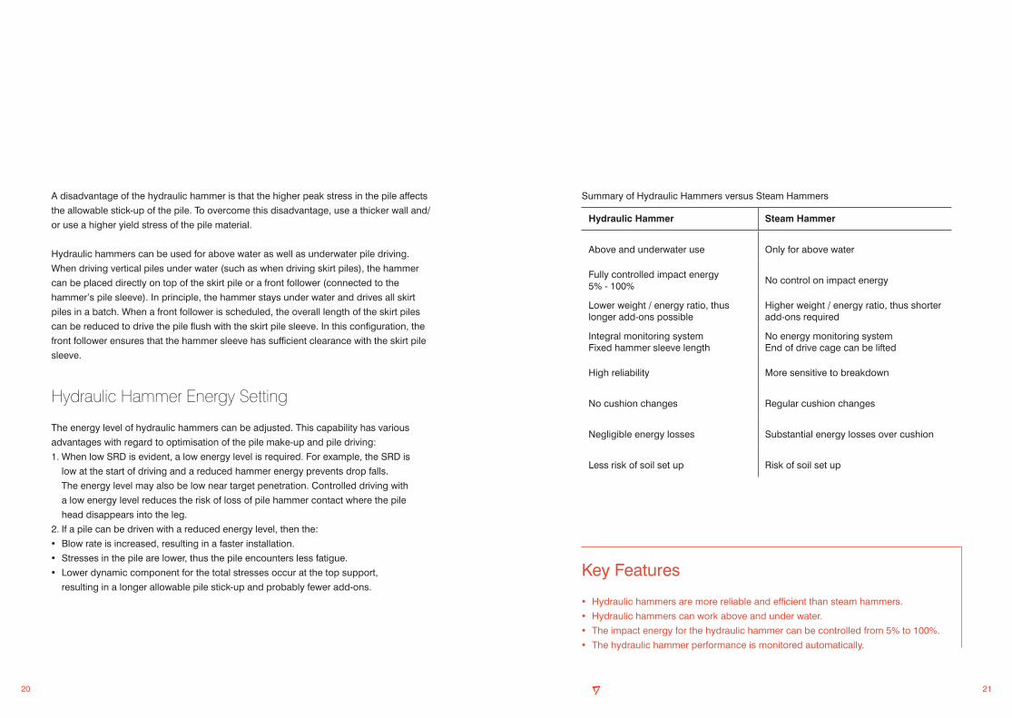
Summary of Hydraulic Hammers versus Steam Hammers
Key Features
• Hydraulic hammers are more reliable and efficient than steam hammers.
• Hydraulic hammers can work above and under water.
• The impact energy for the hydraulic hammer can be controlled from 5% to 100%.
• The hydraulic hammer performance is monitored automatically.
Hydraulic Hammer Steam Hammer
Above and underwater use Only for above water
Fully controlled impact energy 5% - 100%
No control on impact energy
Lower weight / energy ratio, thus longer add-ons possible
Higher weight / energy ratio, thus shorter add-ons required
Integral monitoring systemFixed hammer sleeve length
No energy monitoring systemEnd of drive cage can be lifted
High reliability More sensitive to breakdown
No cushion changes Regular cushion changes
Negligible energy losses Substantial energy losses over cushion
Less risk of soil set up Risk of soil set up
A disadvantage of the hydraulic hammer is that the higher peak stress in the pile affects
the allowable stick-up of the pile. To overcome this disadvantage, use a thicker wall and/
or use a higher yield stress of the pile material.
Hydraulic hammers can be used for above water as well as underwater pile driving.
When driving vertical piles under water (such as when driving skirt piles), the hammer
can be placed directly on top of the skirt pile or a front follower (connected to the
hammer’s pile sleeve). In principle, the hammer stays under water and drives all skirt
piles in a batch. When a front follower is scheduled, the overall length of the skirt piles
can be reduced to drive the pile flush with the skirt pile sleeve. In this configuration, the
front follower ensures that the hammer sleeve has sufficient clearance with the skirt pile
sleeve.
Hydraulic Hammer Energy Setting
The energy level of hydraulic hammers can be adjusted. This capability has various
advantages with regard to optimisation of the pile make-up and pile driving:
1. When low SRD is evident, a low energy level is required. For example, the SRD is
low at the start of driving and a reduced hammer energy prevents drop falls.
The energy level may also be low near target penetration. Controlled driving with
a low energy level reduces the risk of loss of pile hammer contact where the pile
head disappears into the leg.
2. If a pile can be driven with a reduced energy level, then the:
• Blow rate is increased, resulting in a faster installation.
• Stresses in the pile are lower, thus the pile encounters less fatigue.
• Lower dynamic component for the total stresses occur at the top support,
resulting in a longer allowable pile stick-up and probably fewer add-ons.

22 23
Pile Make-Up Aspects for Installation
• Pile-driving hammers required
• Pile wall thickness
• The number of add-ons
• Jacket un-piled stability
• Stoppers, driving head and/or driving shoe requirements
• The SRD at initial pile driving
• Intermediate hard layers
• Driving resistance set up
Effect of Wall Thickness on the Pile Driveability
A stiffer pile is strongly recommended when pile driving through dense sands and/or hard
layers. A stiffer pile requires a lower blow count and thus, the installation has less risk for
premature refusal and/or pile damage. A stiffer pile can be obtained by increasing the wall
thickness above the requirement for the in-place condition. To illustrate this effect, a
comparison of the expected blow count is shown in the graph overleaf: The predictions are
made for a pile with an O.D. of 1219 mm and a W.Th. of 25.4 mm, 38.1 mm and 50.8 mm
(O.D. 48” with a W.Th. of 1”, 1.5” and 2”) in combination with the S-500 hydraulic hammer
driving into very dense sands.
Key Features
• A larger wall thickness improves the pile driveability and reduces the risk of pile refusal.
• A proper pile wall thickness allows a bigger hammer to be used earlier.
• A proper pile wall thickness reduces overall installation time.
• Pile driveability assessment should always be an integral part of the pile make-up design.
• A pile make-up design is “good” when the pile can be driven to penetration with “certainty”
(i.e., the expected blow count remains less than 50 - 60 blows/250 mm for continuous driving).
• When harder layers are met prior to target penetration, the pile make-up should be
designed for a large hammer.
Pile Make-Up and Driveability
General
Often the driveability of the piles is not thoroughly investigated by the engineering
company due to a lack of knowledge or experience. When the pile driveability is to
be assessed on inadequate soil data, the result might be a too optimistic driveability
expectation. For instance, piles are predicted to reach target penetration with a
relatively low-capacity hammer.
The allowable freestanding pile length above the top of pile guide or jacket leg is related to
the weight of the hammer used. A heavier hammer allows for less freestanding pile length.
A check for dynamic stresses combined with bending stresses must always be made.
The criterion is usually static buckling. Hence, the lighter hydraulic hammers tend to allow
greater freestanding pile lengths than steam hammers with comparable energy levels.
At the end of pile driving (target penetration) the soil resistance during driving is usually
high. Therefore, a hammer with appropriate energy to overcome the expected SRD is
required. A high-capacity hammer is heavier than a low-capacity hammer. Thus, the
associated allowable stick-ups become shorter.
If change-out from a smaller hammer to a larger hammer is scheduled, the change-out
should occur before refusal is met. Furthermore, the expected blow count at the start of
driving with the new hammer preferably shall not be greater than 50 - 60 blows/250 mm.
The pile lead section must be made as long as possible considering all installation
aspects, followed by assessment of the add-ons length. Installation aspects such as
allowable freestanding length, pile top interference and pile wall thickness will determine
the add-on length. It is emphasised that the installation is more economical with fewer
add-ons to a pile.

24 25
0 50 100 150 200 250
10
20
30
40
50
60
70
PIL
E T
OE
PE
NE
TRA
TIO
N, m
to m
udlin
e
EXPECTED BLOWCOUNT (for continous driving) blows/250 mm
Best Estimate Dia 48” - W. Th 1.0”
Best Estimate Dia 48” - W. Th 1.5”
Best Estimate Dia 48” - W. Th 2.0”
Target Penetration
Driving Stresses
The hammer blow introduces a stress wave into the pile head. The highest driving
stresses may occur at the following locations in the pile:
1. At the pile head. The anvil should be flat and rest on the full cross-sectional area
of the pile. To avoid pile-head damage, no eccentricity of the stress wave transfer
to the pile head should occur; otherwise, the pile head can be damaged and get
stuck in the hammer sleeve. Consequently, the pile must be cut to remove the
hammer from the pile. A driving head reduces risk of pile-head damage. For each
project, it is recommended to check whether a driving head is required.
2. At the transition of pile to shoe (i.e., in the thinner section of the two wall thicknesses).
Typically, a changeover of wall thickness occurs at the start of the pile shoe. At
that location, the risk is high of overstressing the pile. For example, if the pile toe
is at a hard layer and the hammer is at high energy level, in combination with low
frictional resistance along the pile wall and the pile is made of low-yield stress
material, then the pile could become overstressed at the wall thickness transition
above the pile shoe.
3. Near the pile toe. If almost no frictional resistance is built up, then practically the
full stress wave travels to the pile toe.
4. At interface of a soil layer change. If a pile has a uniform thickness, then the highest
stresses may occur at a transition layer in the soil.
Peak driving stresses by hydraulic hammers are higher compared to driving stresses of
steam hammers for comparable enthru energy level. However, the duration of this peak
value is very short. When driving, the governing criteria with regards to the maximum
allowable stress level in the pile are whichever of the following criteria is met first:
• Start driving is allowed only if the driving (dynamic) stresses in the pile at the top
support level do not exceed 80% - 90% of the pile’s yield strength.
• The total pile stresses (static + dynamic) may not exceed the pile’s yield strength.
• The maximum driving stress shall not exceed 80% - 90% of the yield stress of the piles.

26 27
Vent Holes
When driving a pile under water, the space inside the piles containing water is reduced.
To avoid driving on the water column, the water must be discharged. Vent holes are
provided in the pile or follower to let the water bleed off during driving. The holes shall
not be closed off by the soil or by any structural element (including the grout sleeve) at
any stage of driving under water.
The vent holes must be designed carefully. The holes must be large enough to
discharge the water to keep pace with a fast rate of driving. Periodic inspection of the
holes is also necessary. The holes are an irregularity in the smooth pile or follower wall
and are therefore sensitive to fatigue. Moreover, cracks can initiate along the edges of
the holes. Also, the vent holes in followers are frequently used for suspending the
follower from the hammer. This suspension can be done either with use of a bar through
the holes or with slings. The holes must be checked for bearing stresses and radius of
rounding.
Pile Toe Provision
A driving shoe is a strengthened section at the pile toe. The function of a driving shoe is to:
• Reduce the (inside) driving resistance in clay
• Prevent damage to the pile toe during hard driving
When hard driving is expected in clay or where a high pile toe resistance could be
encountered, a driving shoe of at least one diameter in length is recommended.
The wall thickness of the shoe will be approximately 1.5 times the section above.
Typically, 1 m - 3 m long internal driving shoes are used.
Driving Head
In general, a top 500 mm to 1500 mm of pile section should be removed after the end of
driving of that particular section before splicing another section. This cut-off allowance is
needed to:
• Allow perfect fit up of the next section
• Remove the magnetized pile section (due to driving); otherwise, welding is not possible.
Risk of damage of the pile top is considered to be higher in the following conditions and
should therefore be prevented:
• Hammer blows that are too eccentric in case of battered piles
• Hammer energy levels that are too high
A driving head, which is a strengthened section at the top of a pile, may be required if
driving stresses are such that pile-head damage can be expected. Moreover, a driving
head is used where a front follower is required to ensure a proper fitting between the
front follower and the pile or where very hard driving conditions are expected. The
function of a driving head is:
Without follower:
• To resist eccentricities of the hammer blow
• To prevent local buckling
With a follower the driving head has the following additional purposes:
• To fit the gravity connector of the follower correctly
• To prevent the pile top from splitting open
The length of the driving head should be one to two times the outside diameter of the
pile. A driving head of such length reduces the risk of buckling of the pile head. The wall
thickness of the driving head shall be at least equal to or exceeding the wall thickness of
the pile section below the driving head. When designing driving heads, consider the
driving stresses and material yield strength of the pile and anvil.
28 29
• Soil removal below the pile toe.
Soil below the pile toe is removed either by drilling an undersized hole or by jetting.
Drilling an undersized hole has unpredictable effect on pile ultimate capacity unless
there has been previous local experience under similar conditions. Jetting below the
pile toe has unpredictable results and should be avoided.
• Drilling an oversized hole under the pile toe.
Typically, this form of drilling is done where a pile has to penetrate a calcarenite
or a rock layer.
Use two-stage driven piles.
• A first stage or outer pile (casing) is driven to a predetermined depth, the soil plug is
removed, and a second stage or inner pile (insert pile) is driven inside the first-stage
pile. The annulus between the two piles is grouted to permit load transfer and develop
composite action. In a pre-planned situation, the performance can be good, although
material costs are higher than for normal piles.
• If insert piles are deployed as a remedial action, consideration must be given to
ensure that the grouted connection between the two piles is effective. The initial pile
was not designed for this use. Moreover, special attention must also be given to the
pile’s heavy wall section, when applied, which might now be at the wrong elevation.
Aspects of Premature Refusals
General
When a pile refuses to drive to its target penetration, one or more of the following
sequential actions can be taken:
1. Review of hammer performance using hammer and pile instrumentation.
In case of a driving hammer malfunction, the problem can be solved by improvement
of hammer operation (such as adjustment of hammer energy) or by the use of a more
powerful hammer.
Whatever changes are made, they must keep driving stresses within tolerance.
2. Re-evaluation of the pile design.
Reconsideration of pile loads, deformations, required capacities of individual piles
and the foundation as a whole must be done. This effort may identify available
reserve capacity.
3. Review and interpret the pile driving records in conjunction with pile instrumentation
results. This review could lead to design soil parameters or stratification revisited
and pile capacity being increased.
4. Remedial action.
Possible Remedial Actions
Possible remedial actions include:
• Plug removal.
The soil plug inside the pile is removed by jetting and air lifting or by drilling to reduce
pile driving resistance. If plug removal results in inadequate pile capacities, the
removed soil plug should be replaced by a gravel grout or concrete plug.
The replacement plug must have sufficient load carrying ultimate capacity to replace
that of the removed soil plug. Attention should be paid to plug/pile load transfer
characteristics, particularly in cohesive soils.
30 31
During pile driving, energy losses occur over the anvil and cushion. Furthermore,
energy may be lost due to deformation of the pile head. Therefore, the energy the ram
delivers at impact is higher than the energy that drives the pile. Pile monitoring allows
the measurement of the latter energy, which is the enthru energy and as such gives an
indication of the performance of the hammer.
Pile monitoring also provides the input for the computation of the soil resistance the pile
meets during driving. This dynamic resistance can be converted into estimates of the
static ultimate pile capacity using generally accepted engineering practice. Should
structural damage to the pile occur during driving, the instruments would show it
immediately.
The technique requires that two sets of instrumentation, comprising a strain transducer
and an accelerometer, be mounted on opposite sides of the pile. The instruments are
bolted onto the pile in pre-drilled holes, such that they are not sheared off by the
hammer cage/sleeve or pile sleeve. Hardwire connects the instrumentation to the data
acquisition system onboard the installation vessel.
For the analyses, the strains are converted into forces. The accelerations are integrated
once or twice to determine velocities and displacements, respectively.
From instrumentation, the following information can then be calculated and/or present-
ed per blow in real time:
• Enthru energy, forces, accelerations, velocities and pile head displacements as
a function of time. Hammer performance is monitored on a blow-to-blow basis.
• Soil resistance during driving.
• Values for blow count, blow rate, centricity of the blows, maximum stresses in the
pile and estimated static soil resistance.
Pile Monitoring
General
The design of offshore piles is based on anticipated loading conditions, local soil
conditions and pile installation studies. Foundation piles must meet the design capacity
required for their specific function. Offshore projects especially, require detailed
pre-installation studies that include several assumptions. During or shortly after driving,
these predictions can be checked against actual hammer, pile and soil performance
through pile and/or hammer monitoring.
Certifying agencies, consultants and contractors more often than not require reliable
installation data before accepting offshore installations. This data is especially important
in situations where premature refusal or too-easy driving to target penetration might
occur. The results from pile monitoring can greatly assist in the derivation of the
predicted pile ultimate bearing capacity after full set up has occurred.
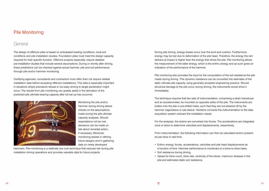
Monitoring the pile and/or
hammer during driving allows
checks on the assumptions
made during the pile ultimate
capacity analyses. Should
expectations not be met,
decisions can be made on
site about remedial action,
if necessary. Moreover,
monitoring assists in refining
future designs and in gathering
data on newly developed
hammers. Pile monitoring is a relatively low-cost technique that reduces risk during pile
installation driving operations and provides valuable data for future projects.
32 33
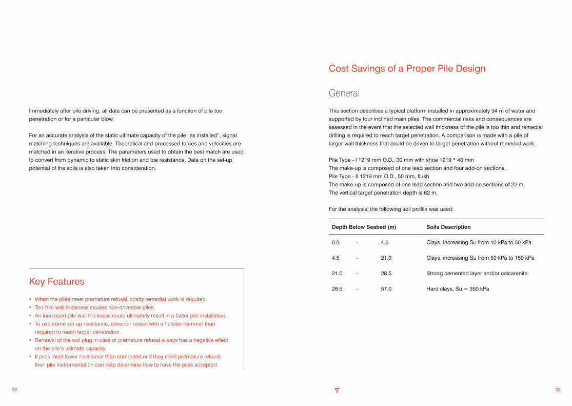
Cost Savings of a Proper Pile Design
General
This section describes a typical platform installed in approximately 34 m of water and
supported by four inclined main piles. The commercial risks and consequences are
assessed in the event that the selected wall thickness of the pile is too thin and remedial
drilling is required to reach target penetration. A comparison is made with a pile of
larger wall thickness that could be driven to target penetration without remedial work.
Pile Type - I 1219 mm O.D., 30 mm with shoe 1219 * 40 mm
The make-up is composed of one lead section and four add-on sections.
Pile Type - II 1219 mm O.D., 50 mm, flush
The make-up is composed of one lead section and two add-on sections of 22 m.
The vertical target penetration depth is 62 m.
For the analysis, the following soil profile was used:
Depth Below Seabed (m) Soils Description
0.0 - 4.5 Clays, increasing Su from 10 kPa to 50 kPa
4.5 - 21.0 Clays, increasing Su from 50 kPa to 150 kPa
21.0 - 28.5 Strong cemented layer and/or calcarenite
28.5 - 57.0 Hard clays, Su = 350 kPa
Immediately after pile driving, all data can be presented as a function of pile toe
penetration or for a particular blow.
For an accurate analysis of the static ultimate capacity of the pile “as installed”, signal
matching techniques are available. Theoretical and processed forces and velocities are
matched in an iterative process. The parameters used to obtain the best match are used
to convert from dynamic to static skin friction and toe resistance. Data on the set-up
potential of the soils is also taken into consideration.
Key Features
• When the piles meet premature refusal, costly remedial work is required.
• Too-thin wall thickness causes non-driveable piles.
• An increased pile wall thickness could ultimately result in a faster pile installation.
• To overcome set-up resistance, consider restart with a heavier hammer than
required to reach target penetration.
• Removal of the soil plug in case of premature refusal always has a negative effect
on the pile’s ultimate capacity.
• If piles meet lower resistance than computed or if they meet premature refusal,
then pile instrumentation can help determine how to have the piles accepted.

34 35
0 50 100 150 200 250
10
20
30
40
50
60
70
Upper Bound
Target Penetration
PIL
E T
OE
PE
NE
TRA
TIO
N, m
to m
udlin
e
EXPECTED BLOWCOUNT (for continous driving) blows/250 mm
Best Estimate
The relatively thin wall of Pile Type I causes higher static stresses (due to hammer
stabbing and environmental conditions) as well as higher dynamic stresses (due to
driving). This make-up not only requires a higher blow count, but also it reduces the
maximum stick-up lengths. The add-on lengths have to be reduced to allow for the
application of the S-500 hammer at the proper energy level.
The Type - I pile meets the refusal criteria when driving through the hard layer at
21.0 m - 28.5 m for the upper-bound condition, and thus pile refusal is to be expected at
that depth and remedial work might be required. Drilling equipment must be mobilised,
at least as a contingency measure. In addition, this pile make-up needs to
be installed with two additional add-ons compared with the Type - II pile make-up.
Mobilisation of a hammer larger than the S-500 is not an option. The wall thickness of
30 mm limits higher energy input, even with the application of the two extra add-ons.
The driveability expectation for the Type - I pile is given on page 34.
The Type - II pile, with a flush wall thickness of 50 mm can be driven with the S-500
hammer through the hard layer found at 21.0 m - 28.5 m and to the target penetration
of 62 m without meeting the refusal criteria even in the upper-bound prediction.
The S-500 hammer can be used at any moment at an energy setting of 90%,
including at restart after welding an add-on.
The driveability expectation for pile Type - II is given on page 36.

36 37
0 50 100 150 200 250
10
20
30
40
50
60
70
Upper Bound
Target Penetration
PIL
E T
OE
PE
NE
TRA
TIO
N, m
to m
udlin
e
EXPECTED BLOWCOUNT (for continous driving) blows/250 mm
Best Estimate
Commercial Implications
An indication of the cost associated with premature refusal and the economical impact
of pile make-up choices is presented hereafter. The figures used are indicative only.
With the volatile market, the ultimate cost to the client could be much higher, especially if
the heavy lift vessel (HLV) rescheduling cost and late first production costs are included.
Premature refusal with the Type - I pile make-up could add about US$ 4 million to the
cost of the project. In contrast, with the Type - II pile make-up an additional cost of only
US$ 213,500 for pile material reduces the risk of premature refusal considerably.
The details of this assessment are elaborated in the next sections.
Additional Costs
Description Type - I US$ Type - II US$
Extra pile material 213,500
Costs associated with difference in:
Installation duration 625,000
Remedial work (including drill rig on standby)
3,039,000
Continue piling and weld backAdd-on (after remedial work)
125,000
Grout spread on board 200,000
TOTAL EXTRA COST 3,989,000 213,500

38 39
Remedial Action
Drilling Out the Piles:
When the piles reach refusal before target
penetration, remedial activity, like drilling out
the piles, is required. In our example, the
installation contractor identified this risk and
mobilised a drill rig to be operational onboard
together with its crew. This advance planning
prevents unnecessary standby of the HLV.
Unfortunately, in many cases, more remedial action is needed when the piles are drilled
out. Often, premature refusal occurs when the top of the pile extends substantially
above the jacket can. Consequently, prior to commencement of drilling, a temporary
cut-off needs to be made and the section needs to be reinstated before driving can be
resumed. It is assumed that remedial work is required at all four piles.
The costs associated with a drilling out of the piles are as follows:
Remedial Costs for Type I Pile
Mobilisation Cost
Mobilisation of the drill rig and its crew: US$ 450,000
Six-man drilling crew on stand by during jacket installation
US$ 24,000
Drilling:
Drill rig working: US$ 20,000/day
HLV spread: US$ 250,000/day
Total HLV spread: US$ 270,000/day
Remedial work:
9.5 days @ US$ 270,000/day US$ 2,565,000
TOTAL REMEDIAL WORK US$ 3,039,000
Courtesy Wirth Maschinen- und Bohrgeräte-Fabrik GmbH
Material
Based on a steel price of US$ 3,500/t, the cost of four numbers piles is compared in the
table below.
Material Cost Comparison
Installation
For the assessment of the overall project duration, it was assumed that all piles can be
driven in batches of four.
The welding of a Type - II pile add-on takes longer due to the increased pile wall
thickness. However, because the add-ons are longer, fewer of them are needed.
Therefore, the total time to weld Type - II add-ons is less. Furthermore, the increased
wall thickness reduces the driving time.
Additional Installation Cost
Consequently, the balance for the pile design is $411,500 in favour of Type II even when
no remedial work is considered.
Type - I Piles (97 mt) Type - II Piles (158 mt)
US$ 339,500 US$ 553,000
DescriptionType - I Piles
2.5 days extra installation time
Type - II Piles
Assumed day rate of US$ 250,000 for a HLV
US$ 625,000 213,500

40 41
Key Features
• An inadequate pile design can increase the installation costs by 50% - 100%.
• An inadequate pile design can result in the platform being delivered late and
thus missing the targeted first production date.
• Additional measures to reach target penetration always hamper the platform
foundation and could cause pile capacity limitations in the future.
• Remedial actions to drive the pile to penetration could cost millions even exceeding
the installation costs.
Continue Driving:
Once the pile has been drilled out, the pile section removed is reinstated before driving
is resumed. It is expected that welding of the last add-on occurs only on the vessel’s
critical path. Stabbing and welding of the last pile section takes approximately 12 hours
at vessel’s day rate at US$ 250,000/day.
Setting a Grout Plug:
The cost associated with the grouting spread is about US$ 200,000. This cost includes
its specialised crew, grouting spread, grout, silos, mobilisation and so on to set four
numbers of grout plugs; one in each pile.
Conclusions
1. A top-quality pile design, which includes superior foundation quality at an economical
price, reduces the risk and associated hazards for the main contractor and operator.
2. A good pile foundation gives the operator the option of future expansion of the
platform. In a properly driven foundation pile, the safety margin with regard to ultimate
bearing capacity is higher than that of a foundation pile that needs remedial activities
to reach target penetration.
3. Even when the operator insists on having drilling and grouting equipment onboard
(as a contingency to address the encounter of an unexpected hard layer) a good
driveable pile remains much less expensive than a pile that encounters refusal.
4. The “total installed cost” for a good driveable pile is less than for foundation concepts
focusing on material cost only.

42 43
Acknowledgements
The author thanks Mr. Dirk Pluimgraaff of Conewel BV for his contribution to this
booklet. His expertise on pile driveability and pile monitoring, his enthusiasm and his
continuous aim to include related cases have made this booklet more extensive,
complete and relevant.
If the reader has any questions or any suggestions, please do not hesitate to contact us.
Aart Ligterink,
Manager Marketing and Business Development
Jan-Peter Breedeveld,
Engineering Manager
Dirk Pluimgraaff
Zoetermeer, May 2009
Seaway Heavy Lifting Engineering B.V.
The Netherlands
Tel: +31 79 363 77 00
Fax: +31 79 363 77 77
Web: www.shl.nl
Notes

44 45
NotesNotes

46
Notes

Disclaimer
This Pile Driveability and Installation booklet gives general information about foundation
pile installation for fixed platforms. It is subject to change without notice.
Seaway Heavy Lifting Engineering (SHL) ensures that the information contained is
reliable. However, SHL does not warrant its accuracy and completeness, nor the
opinions, analyses and furnished information in any way. SHL shall not in any case or
circumstance be held responsible or liable for any errors in this booklet, neither for any
cost or claims whatsoever caused directly or indirectly by interpretation or usage of, or
reliance upon, any information contained in this booklet.
Published in May 2009
By Seaway Heavy Lifting Engineering B.V.
The Netherlands
Copyright © Seaway Heavy Lifting Engineering B.V.
All content in this Pile Driveability and Installation booklet is the property of SHL and
protected by copyright. All rights reserved. You may copy this booklet for personal, non-
commercial use only. You may not modify, publish, transmit, transfer or sell, reproduce,
create derivative work from, distribute, perform, display, or in any way exploit any of the
content, in whole or in part, except as expressly permitted in writing by SHL.