Embed Size (px)
Citation preview

Portable Appliance TestingA Practical Guide
www.seaward.co.uk

The Apollo Series. Making life simpler.
Visit www.apollo-series.com or call +44 (0)191 587 8741Follow us on Twitter: @SeawardPAT #Apolloseries
Apollo 500With advanced data transfer andstorage features, a great value‘plug and play’ PAT tester
Apollo 600A multi-tasking PAT, the all in oneHealth and Safety management
tool with camera
PATGuard 3The ultimate PAT testingand Health and Safetymanagement software
Excellencemade simpleAt a price youwouldn’t believe

Contents
2. Legislation 02
3. Who has responsibility? 03
4. Competence, Training andExperience 03
5. Types of Equipment 04
6. Classes of Equipment Construction 07
7. The Inspection Process 07
8. Combined Inspection andTesting Procedure 09
9. Electrical Tests 13
10. Frequency of inspection and testingbased on risk assessment 18
11. Record Keeping 20
Appendix 23
Seaward:making yourlife easier andmore efficientWorld-Leading Electrical TestEquipment from Seaward
At Seaward Group, we have over 70 years in thedesign and manufacture of innovative electricalsafety test equipment. Today, our first-class rangeof products serves a wide variety of testing andprecision measurement applications.
For the last 30 years we’ve moved ourdevelopments on. Our portable appliance testersare the benchmark for the portable appliancetesting (PAT) market and are regarded as numberone by the industry. Our PAT testing equipmenthas always been designed with the needs of ourcustomers in mind. Safety in the workplace is ofparamount importance and our testers providethe quick and effective key to electrical equipmentpreventative maintenance programmes. That’swhy each Seaward PAT tester is backed by ahuge range of accessories, printers, assetmanagement software and technical support.Peace of mind is guaranteed for our customersbecause they know that help and advice is onlya phone call away.

2. Legislation
Although reference is made to legislation, thisguide should not be considered to be legaladvice. The reader should refer to the specificlegislation and seek legal advice wherenecessary, which may vary from time to time.
Health and Safety at Work Act 1974 (HSW 1974)places a duty of care on both the employer andemployee to ensure the safety of all persons usingthe work premises.
Management of Health and Safety at WorkRegulations 1999 state that every employer shallmake suitable assessment of the risks to health andsafety of his employees to which they are exposedwhilst at work and the risk to the health and safety ofpersons not in his employment arising of or inconnection with the conduct by him of hisundertaking.
The Management of Health and Safety at WorkRegulations 1999 also state that:
Every employer shall make a suitable andsufficient assessment of the risks to the healthand safety of his employees to which they areexposed whilst they are at work.
Where the employer employs five or moreemployees, he shall record the significantfindings of the assessment.
Electricity at Work Regulations 1989 apply toevery type of electrical equipment and state: “Asmaybe necessary to prevent danger, all systems shall bemaintained so as to prevent, so far as is reasonablypracticable, such danger.” (Regulation 4(2))
Provision and Use of Work EquipmentRegulations 1998 places general duties onemployers and lists minimum requirements for workequipment to deal with selected hazards whateverthe industry.
The Regulations implement an EUDirective aimed atthe protection of workers and the “general duties” willrequire the need to:
a. Make sure that equipment is suitable for theuse for which it is provided.
b. Take into account the working conditions andhazards in the workplace.
c. Ensure equipment is used only for theoperations for which, and under conditions forwhich, it is suitable.
d. Ensure that equipment is maintained in anefficient state, in efficient working order and ingood repair.
e. Provide equipment that conforms to EUproduct safety directives
f. Plus certain other general duties and specificrequirements etc.
HousingAct 2004 (England andWales) introduceda new method for assessing risk in residentialproperties, called the Housing Health and SafetyRating System, to provide a safe and healthyenvironment for any potential occupiers or visitors.This includes portable electrical equipment and thecondition of associated leads and plugs should betaken into account if they are provided as part of arented dwelling. Portable appliance testing is onemethod of ensuring that electrical equipment is safefor continued use.
2

Housing (Scotland) Act 2006 defines the statutoryrequirements that have to be met by a privatelandlord and includes the electrical installation andelectrical appliances. The landlord must ensure thatthe property meets the requirements at the start ofthe tenancy and at all times during the tenancywherethe landlord is made aware of possible defects.
3. Who has responsibility?
Users of Electrical Equipment
Users of electrical equipment have a responsibility toensure that equipment they use has no obviousvisual damage or defects. The employer has aresponsibility to provide andmaintain a safe plant forevery employee to use (HSW Act 1974 Sect 2(a)).This requirement is endorsed by the (EAWR 1989)Regs 4(1) and 4(2) with specific reference to electricalequipment. The (EAWR 1989) Reg 3(1) also placesthe same duties upon the self-employed.
Administrators
The IET Code of Practice gives advice to personsmanaging maintenance schemes. Administrators ormanagers of premises are required to understandand apply the legislation and assess the risks inrespect of electrical equipment and applianceswithintheir charge. Administrators have a legal responsibilityto ensure that the electrical equipment in their chargeis safe.
Test Operative
The person performing the inspections and tests onan item of equipment should be competent to carryout the inspections and tests, assess the results andthe conditions in which the item is being used andstate whether the item is safe for continued use.Training and experience will both be necessary.
4. Competence, Training and Experience
The User
Users may require training in identification of defectsthat can occur in electrical equipment. Users shouldbe aware that:
a. Equipment that is faulty or suspected of beingfaulty should not be used.
b. Equipment that is faulty should be labelled andremoved from service immediately.
c. The administrator or manager should benotified.
The Duty Holder
The duty holder, normally amanager or supervisor, isrequired to know their legal responsibilities as laiddown in the Electricity atWork Regulations 1989 andhave a legal responsibility to ensure that equipmentin their charge is safe.
Duty holdersmay require training to allow them carryout risk assessments, maintain records ofinspections, tests and repairs of equipment andmanage the inspections and tests at appropriateintervals. Duty holders are required to interpret therecorded results and take appropriate actions or toprovide relevant information and reports to a moresenior person within the organisation. Competenceto interpret records and results is achieved byappropriate training and experience.
The Test Operative
In the context of safety testing, the term “competence”refers to a person’s ability to perform the task withoutdanger to themselves or others and to make a validjudgement based on the results, as towhether the unit
3

4
under test is safe to use and is likely to remain safe atleast until the next scheduled test date.
It will be appreciated that the test person will requirecertain knowledge and information to enable suchvalid prospective judgements to bemade. In additionthe test person will require both the knowledge andthe information necessary to make judgementsregarding the testing process and its safety and theskill and ability to put such judgements into practice,this producing a safe system of work. Training andexperience will both be necessary.
It is suggested that the following criteria areconsidered:
a. An adequate knowledge and practicalexperience of electricity and its hazards.
b. A clear understanding of precautions requiredto avoid danger.
c. The ability to recognise at all times whether it issafe for work to continue.
d. The ability to identify equipment and appliancetypes to determine the test procedures andfrequency of inspection and testing.
e. Adequate understanding of the operatingprinciples of both the test equipment and theunit under test.
f. The ability to create test records and takeresponsibility for the work.
g. Adequate knowledge of the required safetystandards.
h. Adequate knowledge of possible hazards at a“strange” site.
The tester’s skill and ability should encompass:
a. Adequate experience of relevant electricalwork.
b. Adequate experience of appliance testing andthe test equipment.
c. Adequate training where (b) cannot beotherwise satisfied.
d. Experience in the interpretation of results.
e. Practical “technical” experience of the type ofequipment being tested.
Suitable sources of information may include:
a. Employer’s safety manuals or instructions.
b. Equipment manufacturer’s handbooks.
c. British Standards (see Appendix).
d. Health and Safety Executive (HSE) GuidanceNotes (see Appendix).
e. IET Code of Practice for In-Service Inspectionand Testing of Electrical Equipment.
Managers and Supervisors responsible for testingpersonnel should adjust their degree of supervision totake into account any inadequacy of the test person.The (EAWR 1989) Reg. 3 places a duty on the selfemployed to assess their own competence andsubsequently to work within their limitations.
5. Types of Equipment
The IET Code of Practice applies to equipmentsupplied at voltages up to and including 1000VACor1500VDCbetween conductors or 600VACor 900VDC. between conductors and earth including single,two and three-phase equipment supplied at 400V,230V and 110V and at extra-low voltage includingSELV (Separated Extra-Low Voltage). Several typesof electrical equipment are defined in the IETCode ofPractice.

Portable Equipment
An appliance of less than 18kg in mass that isintended to be moved whilst in operation or anappliance which can easily be moved whilst inoperation or an appliancewhich can easily bemovedfrom one place to another e.g. vacuum cleaner,toaster, food mixer, etc.
Hand Held Equipment or Appliances
This is portable equipment intended to be held in thehand during normal use e.g. drill, hair dryer.
The risk of damage which may cause the safety ofhand held equipment to be compromised can behigh. Also, the use of some hand held equipmentcarries a high risk due to the very nature of its use i.e.the user is in direct contact with the equipment.
Moveable Equipment (Transportable)
This equipment is either:
18kg or less in mass and not fixed, e.g electricfire or:
Equipment with wheels, castors or othermeans to facilitate movement by the operatoras required to perform its intended use e.g. airconditioning unit
Such equipment may be considered “transportable”rather than portable, but will still be connected to itssupply where applicable by a flexible cable and plug.The risk of damage which may cause the safety oftransportable equipment to be compromised can behigh. Also, the use of some transportable equipmentcarries a high risk due to the very nature of its use(e.g. a high pressure steam/water cleaner) and insuch circumstances transportable equipment canpresent a greater hazard than most portableequipment, therefore the requirement to periodicallytest must also apply to transportable equipment.
Experts in what we do.
5

Stationary Equipment or Appliances
This equipment has a mass exceeding 18kg and isnot provided with a carrying handle e.g. refrigerator,washing machine
Fixed Equipment/Appliances
This equipment or an appliance which is fastened toa support or otherwise secured in a specific locatione.g. bathroomheater, towel rail. Fixed equipment canalso be movable or portable equipment, whenconnected to the fixed installation via a fusedconnection unit (FCU), for security purposes. Thispractice is common in areas used by the generalpublic, e.g. hotels, changing rooms etc. Equipmenttypes connected in this way are numerous e.g.kettles, lamps, hair dryers etc
Appliances or Equipment for Building In
This equipment is intended to be installed in aprepared recess such as a cupboard e.g. a built-incooker.
Information Technology Equipment
This equipment includes electrical businessequipment such as computers, mains poweredtelecommunications equipment and otherequipment for general business use e.g. printers,photocopiers, typewriters etc.
Extension Leads and RCD ExtensionLeads
Extensions leads are usedwhere an itemof equipmentrequires connection to amains supply but a convenientoutlet is not available. An RCD extension lead is anextension lead that is fittedwitha residual currentdevice.
6

Multi-way Adaptors and RCD Adaptors
Multi-way adaptors are used where sufficient mainsoutlets are not available. RCD adaptors are used toprovide protection for users of portable equipment,particularly when used outdoors.
6. Classes of Equipment Construction
Before an item of equipment can be tested theconstruction class must be determined in order toidentify the appropriate tests. The equipment to betested will normally be constructed in one of threebasic classes, designated Class I, II or III.Constructional methods are summarised below, fulldetails can be found in BS2754.
Class I equipment is constructed such thatprotection against electric shock does not rely onbasic insulation alone. In addition to basic insulationaround live internal parts, exposed conductive partsare connected to the protective conductor in thefixed wiring of the electrical installation. Class Iequipment relies upon a connection to the protectiveconductor to prevent exposed conductive partsbecoming live in the event of a failure in the basicinsulation.
Class II equipment is constructed such thatprotection against electric shock does not rely onbasic insulation alone. In addition to basic insulationaround live internal parts, supplementary insulation isprovided, there being no provision for connection ofexposed conductive parts to the protectiveconductor. Such equipment is often described as“double insulated” and should carry the symbol .
Class III equipment is equipment in which protectionagainst electric shock relies on a supply from a
separated extra-low voltage source (SELV). In a SELVsupply the voltage is less than 50V rms and noexposed conductive parts are connected to theprotective conductor.
Note: Not all double insulated equipment bearsthe mark, however, if the mark is applied theequipment must be double insulated. For thepurposes of electrical safety testing, if a piece ofequipment does not bear the it should betreated as Class I.
7. The Inspection Process
User Check
User checks are performed before equipment isplugged in and switched on. The check involves avisual inspection of the mains plug, mains flex andthe appliance for obvious signs of damage ordegradation. An assessment should also be madeof the suitability of the environment and the purposefor which the equipment is to be used. User checksare an important safety precaution as the user of theequipment is most familiar with its operation. Userchecks do not need to be recorded unless a problemis discovered, in which case the equipment shouldbe labelled to show it is not to be used and removedfrom service as soon as possible. The administratoror manager should be notified.
Formal Visual Inspection
In practise, many equipment defects can be foundduring a formal visual inspection. Many potentialhazards arise due to the way in which a piece ofequipment is used or abused. For example,portable equipment may be prone to being droppedor a piece of movable equipment with a long,
7

trailingmains flexmay be damaged as the equipmentis moved around. Potential hazards such asenclosure damage, damage to the mains flex, signsof overheating, incorrectly fitted mains plugs,incorrect fuses etc. can be identified by a thoroughvisual examination.
A formal visual inspection carried out by a competentperson will make the greatest contribution tominimising risk and eliminating potential safetyhazards. Advice on the frequency of formal visualinspections is given in Table G (see page 19).
A formal visual inspection should include aninspection of the following:
1. Manufacturer’s instructions
a. The equipment should be installed andused in accordance with the manufacturer’sinstructions.
b. The correct voltage, frequency and currentrequirements should be verified.
c. Requirements for ventilation or heatdissipation should be met.
2. Environment
a. Suitability of the equipment for theenvironment or purpose for which it isbeing used e.g. risk of mechanical damage,exposure to weather, temperature, fluids,corrosives, flammable materials.
3. Switching of equipment
a. The inspector should determine whetherthere are suitable means of disconnectingthe equipment from the mains supplyunder normal use, to carry outmaintenance and in the event of anemergency (if applicable to the equipment).
4. User feedback
a. Where possible the user of the equipmentshould be consulted as to whether thereare any known problems or faults. The usermay be aware of intermittent problems thatmay not be apparent during the inspection.
5. The equipment enclosure/casing
a. Physical damage such as cracks or chemicalcorrosion. Particular attention should be paidto areas around switches, fuses, protectivecovers andmains couplers where damagemay result in live parts becoming exposed.
b. Signs of overheating.
c. Signs of ingress of fluids or foreign bodies.
6. Mains plugs
a. Correct fit in the mains outlet – not looseand can be removed without difficulty.
b. Cracks or damage.
c. Signs of overheating.
d. Properly tightened off terminal screws.
e. Correct wiring.
f. Mains flex is properly secured by the cablegrip.
g. Correct fuse rating and type.
7. Mains cables
a. Damage, cuts or fraying. Extension leadsshould be checked along the entire length.
b. Joints or connections which are unsafe e.g.taped joints.
c. Appropriate length.
d. Correct rating for the equipment.
8. RCD protected adaptors or extension leads
a. Correct operation of the RCD shouldbe confirmed.
8

Operator accessible fuses on the outside of theequipment should be checked for correct type andrating. If the equipmentmanufacturer has specified aparticular rating for the plug fuse, this should also bechecked. If themanufacturer has not specified a fuserating for the plug the maximum current carryingcapacity is detailed in Table H (see page 22) relatedto the cross-sectional area of the cable conductors.Ensure that properly manufactured cartridge fusesare used and that fuses have not been replacedwitha metal bar, wrapped in metallic foil or similarnon-standard method.
Note: The requirements of a formal visualinspection will vary according to the equipmentbeing inspected and the environment in which itis used. The ‘prompts’ built into SeawardPortable Appliance Testers (Apollo 600,Supernova Elite, Europa Plus and PrimeTestrange) are intended to provide guidance andshould not be taken as a comprehensive list ofitems to be checked during a formal visualinspection.
8. Combined Inspection andTesting Procedure
Safety Considerations
Inspection and testing should only be carried out bya personwho is competent to perform the inspectionand testing and interpret the results obtained.
Preliminary Inspection
Before inspection and testing is carried out the testoperative should obtain a copy of any previous testrecords if they are available. This will allow anassessment to be made of any degradation of theequipment under test.
Before attempting to carry out any electrical safetytests, the following preliminary inspection should becarried out:
a. Ensure that the equipment can bedisconnected from the mains supply and otherpower sources. If permission is received,disconnect the equipment from the supply.
b. Disconnect the equipment from all otherequipment, communication links and telecomlines.
c. Where the equipment under test has theprovision to supply mains power to otheraccessories (for example a monitor poweredfrom PC base station) the mains connectioncan remain in place during the tests.
d. Ensure that equipment is not in contact withextraneous metalwork such as parts of officefurniture.
e. Thoroughly inspect the equipment under testfor damage, as described in Formal VisualInspection.
9

f. Inspect the mains plug as described in FormalVisual Inspection.
g. Inspect the mains cable as described in FormalVisual Inspection.
h. Assess the suitably of the equipment for theenvironment.
i. Where possible, consult the user as to whetherthere are any known problems with theequipment.
Note: Special care should be taken whereequipment is powered from an uninterruptiblepower supply (UPS) or has internal batterybackup.
In-Service Tests
The IET “Code of Practice for In-Service Inspectionand Testing of Electrical Equipment” recommends asystem of periodic inspection and testing, with up-to-date records, as a means of demonstratingcompliance with the Electricity at Work Regulations1989. Most companies and organisations that wishto comply with the requirements of the Electricity atWork Regulations 1989 will carry out in-service testsat intervals determined by risk assessment.
The order in which the tests are performed isimportant to the safety of the test operative. Thetesting sequence of Seaward portable appliancetesters is designed to contribute towards a safesystem of work. The sequence should always be:
1. Earth continuity test
2. Insulation resistance test
3. Protective conductor/touch current test oralternative/substitute leakage test
4. Functional check
An insulation test should always be carried out beforeattempting any tests which involve applying mainspower to the equipment under test as it may detecta dangerous insulation failure.
The recommendations given by the IET Code ofPractice for In-Service Testing of Electrical Equipmentare as follows:
Class I Appliances
Earth continuity test
Insulation resistance test or protectiveconductor current test or alternative/substituteleakage
Functional checks
Class II Appliances
Insulation resistance test or touch current testor alternative/substitute leakage test
Functional checks
Fixed Equipment or Appliances
Fixed equipment or appliances are more difficult toinspect and test due to their connection to the fixedwiring of an installation. This does not mean that onlyvisual inspections are required for these types of
10

equipment and they should be subjected to a fullcombined inspection and test at intervals determinedby risk assessment.
Testing fixed equipment or appliances must be carriedout by a competent person, in accordance with thespecific tests for particular class of equipment. Theperson carrying out the inspection and testing:
must be competent to carry out safe isolationprocedures,
must be competent to carry out this morecomplex arrangement of work,
must ensure safe systems of work areobserved at all times,
must ensure all inspections and tests, arerelevant to the class of equipment.
Where the frequencies of any combined inspectionand testing for permanently fixed equipment,determined by risk assessment, are similar to thosefor the fixed installation, inspection and testing canbe undertaken during periodic inspection and testingof the fixed installation. Where equipment could besubjected to higher use or have a greater risk ofdamage, additional formal inspections may berequired.
Appliance Cable Sets
A3-core appliance cable should be tested as aClassI appliance and the following tests should be made:
Earth continuity
Insulation resistance
Wiring polarity check
A 2-core appliance cable should be tested as aClassII appliance and the following tests should be made:
Insulation resistance
Wiring polarity check
Note: Seaward portable appliance testers areequipped with appliance cable tests thatautomatically perform all of the recommendedtests, including wiring polarity.
Extension leads, multi-way adaptorsand RCD adaptors.
Extension leads and multi-way adaptors are testedas a Class I appliance and the following tests shouldbe performed:
Earth continuity
Insulation resistance
Wiring polarity check
When the extension lead or multi-way adaptor isfitted with an RCD, the RCD must have a ratedresidual operating current (the current at which theRCD is designed to operate) not exceeding 30mA.
11

Testing After Repair
The IET Code of Practice recommends thatequipment that has been repaired should beinspected and tested either in accordance with themanufacturer’s production tests or in-service tests.The decision is based upon the type of equipmentand the nature of the repair.
Class I Appliances
Earth continuity test
Insulation resistance test
Dielectric strength test
Protective conductor current test
Functional checks
Class II Appliances
Insulation resistance test
Dielectric strength test
Touch current test
Functional checks
Testing after repair is performed to ensure that therepair has not compromised the electrical safety ofthe electrical equipment and this is reflected by therecommended electrical tests. For example, the earthcontinuity test will demonstrate that all protective earthconnections have been replacedwhen the applianceis reassembled. Similarly, the dielectric strength testis a useful means of ensuring that all insulatingmaterials has been correctly reassembled and thatthe insulation on live conductors has not beendamaged during reassembly, for example, whenwires are trapped or damaged by fixing screws.
12
The IET Code of Practice for In-Service Inspectionand Testing of Electrical Equipment also recommendsthat the operation of the RCD should be checkedusing an RCD test instrument to determine that thetrip time is within the limits specified in Table A below:
RCD Type Maximum tripping time at ratedcurrent
Maximum tripping time at 5x ratedcurrent
Portable devices to BS 7071 RCD trip time ≤ 200ms RCD trip time ≤ 40ms
BS EN 61008BS EN 61009 RCD trip time ≤ 300ms RCD trip time ≤ 40ms
TABLE A
Note: Many Seaward portable appliance testers are equipped with an RCD trip time test for testingthe operation of RCDs in accordance with the recommendations of the IET Code of Practice forIn-Service Testing of Electrical Equipment.

Experts in what we do.
13
Testing Hire Equipment
The IET Code of Practice does not coverinspection and testing of equipment or appliancesthat are used for commercial gain hire purposes.Equipment hire companies should refer to the HireAssociation of Europe (HAE) and Event HireAssociation (EHA) document, HAEEST2012:‘Guidance on Electrical Safety Testing in the HireIndustry’, which gives guidance on in-serviceinspection and testing for hire equipment prior toits release to customers/clients.
The HAE/EHA Code of Practice recommends thatcombined inspection and testing should compriseof some or all of the following:
Visual Inspection
Earth continuity test
Insulation resistance or protectiveconductor/touch current test
Dielectric strength test
Load (Run) Test
Polarity check
Functional checks
9. Electrical Tests
Earth Continuity
This test is performed onClass I equipment ormainscables and is used to verify the integrity of theconnection between the protective conductor and allexposed metal parts intended to be connected tothe protective conductor.
The IET Code of Practice for In-service Inspectionand Testing of Electrical Equipment recommendseither of the following:
A continuity measurement with a short circuittest current within the range 20mA to 200mA.
orA continuity measurement with a test currentnot less than 1.5 times the rating of the fuseand no greater than 25A for a period ofbetween 5 and 20 seconds.
Note: Some appliances, for example ITequipment, may have accessible metal partswhich are connected to earth for functional orshielding purposes only. If the high current testoption above is used, the test current will flowthrough sensitive components or wiring notintended to provide a protective earthconnection. Inappropriate use of a high testcurrent may damage the equipment under test.If in doubt, a low test current should be used.
When testing equipment with a mains cable, thecontinuity test is made between all accessibleearthed metal parts of the equipment and theearth pin of the plug. When testing equipmentwithout a mains cable, the continuity test is madebetween the earth pin of the mains input socketand all exposed metal parts. The resistancemeasurement should be observed while flexingthe cable and an inspection of the flexible cableterminations at the equipment and the plug or flexoutlet should be made. Variations in measuredresistance should be investigated.
The measured resistance should not exceed thevalues given in Table B on the following page.
Note: Nominal values for resistance of theprotective conductor of the supply cable aregiven in Table G (see page 22)

Where possible, it is advisable to test equipmenttogether with its supply cable. If the mains cable isnot detachable, no practical alternative exists.
Care should be taken to ensure that test connectionsto the equipment under test make clean metal-to-metal contact otherwise contact resistance mayintroduce significant errors.
It is possible for Class I equipment to have conductivemetal parts which are not accessible to the operator,accessiblemetal partswith protection against electricshock being provided by double or reinforcedinsulation or to have ‘unearthed’ metal parts whichare in casual or fortuitous contact with earthedmetal.In this case no earth continuity test is specified.
Insulation Resistance
Insulation resistance is measured by applying a testvoltage of 500V DC and measuring the resistance.
When testing a Class I appliance the voltage isapplied between both live conductors (phase andneutral) and the protective conductor (earth).When testing a Class II appliance, the test voltageis applied between both live conductors (phaseand neutral) and a test probe. The test probeshould be applied to any exposed metal parts orany suspect parts of the enclosure whereconductive material may have accumulated.Multiple tests may be required.
Modern portable appliance testers produce a testvoltage which is current limited. The voltage is notdangerous but could be uncomfortable.Appliances should not be touched during aninsulation test.
This test may not be suitable for certain types ofappliance. In the case of equipment fitted withmains filters, voltage limiting devices or surge
Class of Construction Minimum Insulation Resistance
Class I heating and cooking equipmentWith a rating ≥ to 3kW 0.3Mohm
All other Class I equipment 1.0Mohm
Class II equipment 2.0Mohm
Class III equipment 0.25Mohm
TABLE C Minimum Acceptable Insulation Resistance Values
14
TABLE B
Appliances with a supply cable (0.1 + R) ohm
Appliances without a supply cable 0.1 ohm
3 core appliance mains cables (0.1 + R) ohm
Extension leads, multi-way adaptors and RCD adaptors (0.1 + R) ohm
Note: R is the resistance of the protective conductor of the supply cable

Experts in what we do.
15
protection it may not be possible to obtain asatisfactory insulation resistance measurementwith a 500V DC test voltage. IT equipment whichdoes not comply with BS EN 60950 may bedamaged by the 500V DC test voltage.
An alternative/substitute leakage, an insulationresistance test at a reduced test voltage such as250V DC or a protective conductor/touchcurrent measurement may be more appropriate.
This test should be performed with theequipment switch ON. Some electronicequipment may contain mains filter circuitsconnected between live/neutral and earth.Such devices could cause the insulationresistance to be less than specified. Themanufacturer/supplier must be consulted inthese cases as to the acceptable value ofinsulation resistance.
Insulation Resistance for Heating andCooking Appliances
For equipment such as portable cookers theinsulation resistance when cold can be very low.Switching on the appliance for a period of timedrives out any absorbed moisture, enabling morerealistic resistances to be obtained.
Alternative or Substitute LeakageMeasurement
Alternative or substitute leakage is measuredusing a technique similar to that used whenmeasuring insulation resistance. A test voltage isapplied between both live conductors (phase andneutral) and the protective conductor (earth)during a Class I test, or, a test probe connected tothe equipment enclosure during a Class II test.The resultant current is measured and then scaled
to indicate the current that would flow at thenominal supply voltage.
The test voltage is 50Hz AC and normally in therange of 40V to 250V. The test voltage is currentlimited and so there is no hazard to the testoperative. As the test voltage has the samenominal frequency as the mains supply theleakage paths are similar to those found when theequipment is in operation. Similarly, because thetest voltage is not greater than the nominal supplyvoltage of the equipment under testmeasurements are not affected by transientsuppressors, MOVs or other voltage limitingdevices.
Portable appliance testers automatically make thenecessary connection between the live andneutral conductors and apply the correct scalefactor to the measured current. The equipmentunder test must be switched ON during the test.
Dielectric Strength Test
This test is also known as the “high voltageleakage test”, “high pot test” or “flash test” and isa ‘type approval test’ or ‘production test’.

Standard Basic Insulation SupplementaryInsulation
ReinforcedInsulation
EN 60335 Safety of Household Electrical Appliances 1000V 2500V 2500V
EN 60065 Audio, Video and Similar Electronic Apparatus– Safety Requirements 1500V 2500V 2500V
EN 60950 Safety of Information Technology Equipment,Including Electrical Business Equipment 1500V 1500V 3000V
Table D Dielectric Strength Test Voltages
16
Test voltages of 1500V AC and 3000V AC areavailable on selected Seaward testers that includethis test.
The 1500V AC is applied at the mains plug of theappliance under test, between the protective earthconductor and the live/neutral conductors connectedtogether. The 3000 V AC test is applied between thelive/neutral conductors connected together at themains plug and a high voltage test probe applied tothe enclosure of the appliance under test. No otherconnection is necessary.
EN 60335 “Safety of household and similar electricalappliances” allows a high voltage leakage current of0.75mA/kW with an overall maximum of 5mA. AsSeaward testers are intended to test equipment witha maximum power consumption of approximately3kVA the pass level defaults to 3mA. Equipment toBS2769 “Hand held electric motor operated tools”requires a ‘flash’ test voltage of 1.5kV and themaximum permitted leakage is 0.75mA. The testshould be conducted with the unit under testswitched ON.
Table D defines the test voltages for a range ofappliances
Warning:During flash testing, close proximity tothe high level of charge present could causedamage to certain types of electronic equipmentwhich incorporates semi-conductor devices.The advice of the equipment manufacturershould always be sought before testing whensuch conditions are suspected.
The IET Code of Practice does not recommend theuse of the dielectric test as an in-service test but doesstate that it may be appropriate after a repair inaccordancewith themanufacturer’s production or in-service tests, depending on the equipment and thenature of the repair.
The Hire Association Europe (HAE) and Event HireAssociation (EHA) Guidance on ElectricalSafety Testing in the Hire Industry includesrecommendations and guidance on the use ofdielectric strength testing.
Preload Check
Seaward portable appliance testers automaticallyperform a pre-check before tests which involvesapplying mains power to the equipment undertest. This is included to protect the test personfrom potential hazards produced by a very lowimpedance or short circuit being present between

Class of Construction Maximum Permissible Current
Portable or hand-held Class I equipment 0.75mA
Class I Heating appliances 0.75mA or 0.75mA per kW, whichever is greater, with amaximum of 5mA
Other Class I equipment 3.5mA
Class II equipment 0.25mA
Class III equipment 0.5mA
Table E Protective Conductor/Touch Current Limits
Experts in what we do.
17
LIVE and NEUTRAL. The test should beconducted with the equipment switched ON.
Load Test
A load test is not a ‘required’ safety test, howeverit can provide useful information regarding theoperation of the equipment under test. Theportable appliance tester will apply the supplyvoltage to the equipment under test and measurethe power consumption in kVA or load current inamperes.
The test is included since a higher power thanexpected from the specification may indicatereduced functional efficiency. A significant changefrom a previously recorded figure may provide anearly warning of bearing failure in an electricalmachine or shorted turns within a transformer, bothconditions indicating the need for maintenance.Abnormally low power could be the indication of anopen circuit, ruptured fuse or other form of fault.
Protective Conductor/Touch CurrentMeasurement
The protective conductor/touch current is measuredfrom live parts to protective earth for Class Iequipment, or from live parts to accessible metal
parts of the enclosure on Class II equipment undernormal operating conditions. This test is analternative to the insulation test where the insulationtest is inappropriate. This test will provide evidence ofpossible deterioration of certain components underload andmay indicate that themethod of connectionof the equipment to the supply is inappropriate.
Table E defines the limits for protective conductor ortouch current.
Note: Should the equipment contain a mainsinterference suppression capacitor or filter,some residual leakage will be measured; thiswill not necessarily indicate a fault condition.
Warning: Special care should be takenduring tests where the equipment under testis energised. Portable tools and rotatingmachines etc. should be rendered safebefore the complete test sequence begins.All such machines should therefore bephysically secure and have their cutting,grinding, drilling bits etc. removed wherepossible; where guards are provided theyshould be in place.

18
10. Frequency of inspection based
on risk assessment
Guidance on the frequency of testing and/orinspection is provided in the IET Code of Practiceand in HSE Guidance Notes such as ‘MaintainingPortable Electrical Equipment in Low-riskEnvironments’. The duty holder should determinethe appropriate interval between inspection andtesting based on robust risk assessment.
Risk AssessmentAny risk based assessments are the responsibility ofthe duty holder however a duty holder may enlist theservices of a competent person to assist in thisprocess. Risk assessments should be reviewedregularly to ensure that any control measures areeffective and that there are no changes which mayalter the level of risk. If there are any significantchanges, the risk assessment should be updated.
When assessing risk, the following factors should beconsidered:
1. The environment2. The users3. The equipment class of construction4. The equipment type5. The frequency of use6. Type of installation methods7. Previous records
Guidance on the initial frequency of suggestedinspection and test periods is given in the IET Codeof Practice for In-Service Inspection and Testing ofElectrical Equipment, and can also be found in theHSE publications HSG107 Maintaining PortableElectrical Equipment and INDG236 MaintainingPortable Electric Equipment in Low-RiskEnvironments.
The table overleaf appears in the HSE GuidanceNote HSG107 ‘Maintaining Portable ElectricalEquipment’ and provides suggested initialmaintenance intervals.

Experts in what we do.
19
Type of business User checks Formal visual inspection Combined inspection and test
Equipment hire N/A Before issue/after return Before issue
Battery operated equipment(less than 40 V)
No No No
Extra low voltage (lessthan 50 V ac), telephoneequipment, low-voltage desklights
No No No
110Vequipment
Yes. weekly Yes, monthlyYes, before first use on sitethen 3-monthly
230V equipment Yes, daily/every shift Yes, weeklyYes, before first use on sitethen monthly
Fixed RCDs Yes, daily/every shift Yes, weeklyYes, before first use on sitethen 3-monthly (portableRCDs monthly)
Equipmentsite offices
Yes, monthly Yes, 6 monthlyYes, before first use on sitethen yearly
Heavy industrial/high riskof equipment damage (notconstruction)
Yes, daily Yes, weekly Yes, 6-12 months
Light industrial YesYes, before initial usethen 6-monthly
Yes, 6-12 months
Office information technologyrarely moved, eg desktopcomputers, photocopiers, faxmachines
No Yes, 2-4 yearNo if double insulated, otherwise up to5 years
Double insulated (Class II)equipment moved occasionally(not hand-held), eg fans, tablelamps
No 2-4 years No
Hand-held, double insulated(Class II) equipment, eg somefloor cleaners, some kitchenequipment
Yes Yes, 6 months - 1 year No
Earthed (Class I) equipment,eg electric kettles, some floorcleaners
Yes Yes, 6 months - 1 year Yes, 1-2 years
Cables, leads and plugsconnected to Class Iequipment, extensionleads and battery chargingequipment
Yes
Yes, 6 months - 4years depending ontype of equipment itis connected to
Yes, 1 - 5 years dependingon the equipment it isconnected to
Note: Cables, leads and plugs connected to Class II equipment should be maintained as part ofthat equipment. Cables leads and plugs not dedicated to an item of equipment should bemaintained as individual items as appropriate. Over time, when you look at the results of userchecks, formal visual inspections and portable appliance tests you will notice trends. These maytell you that you need to look at or test electrical equipment more or less often, depending on thenumber of problems being found. If electrical equipment is grouped together for testing at the sametime, you should use the shortest testing interval in the group rather than the longest. Alternatively,it may be appropriate to group your electrical equipment by testing interval. The IET Code ofPractice has a similar table but with the information presented in a slightly different manner. In someinstances with more detail and specifics, however, the two sets of information are considered tobe consistent with each other.
Table F: Suggested Initial Maintenance IntervalsMaintaining portable electrical equipment HSG107 (3rd. edition) HSE 2013
Co
nstr
ucti
on
20
11. Record Keeping
Although there is no legal requirement to keeprecords of inspection and testing, the HSEMemorandumof Guidance on the Electricity atWorkRegulations 1989 advises that records ofmaintenance including tests should be keptthroughout the working life of the equipment.
In any proceedings for an offence consisting of acontravention of the EAWR 1989 Rep 4 (4).5 and 8to 16 inclusive (i.e. those Regulations requiring“absolute” compliance); Regulation 29 states that itshall be a defence for any person to prove that theytook all reasonable steps and exercised all duediligence to avoid the commission of that offence.
The most effective method for the duty holder toprove that he “exercised all due diligence” etc., is toproduce proper records of the measures taken toprevent the accident. Hence full and accuraterecords made at the time of testing becomeessential, and the managed system designed toachieve this must be in place before the accident.
Step By Step Approach
A step-by-step approach would include thefollowing:
a. Conduct a survey to identify all portable andtransportable appliances which exist with theduty holder’s control.
b. Each appliance should be marked with aunique identification code, cross referencingtest results and inspection details.
c. A register of all equipment should then becreated to include the following details:
1. Identification number
2. Location in which the equipment is kept
3. A description of the appliance
4. Serial number
5. Periods between tests
6. Any other details.
Due to the large number of appliances and the detailsthat must be recorded a computer database is likelyto be the most effective and efficient method of datacollection and storage.
A comprehensive software package, such asSeaward’s PATGuard, will enable the user to set upa detailed database of all items at any particularlocation easily.
By recording the information outlined in (c) aboveworking documents can be produced which are auseful aid to proficiency and safety. For example awork schedule can be generated grouping productsby test date, task sheets can be printed providing theperson conducting the tests with a list of all items duefor testing, together with their location, identificationnumber etc.
Use of Advanced Portable ApplianceTesters
Where advanced portable appliance testers such asSeaward’s Apollo 600, Supernova Elite, Europa Plus,and PrimeTest 300/350 testers are used, data canbe transferred directly from the instrument to thedatabase providing automatic creation or update ofrecords.
In such situations reports of untested appliances andthose which failed the tests can be produced andsubmitted to the duty holder for the appropriateaction to be taken, this insures the investigation isthorough and avoids oversight.

Action on Completion of Tests
Any equipment found unsafe must immediately beremoved from use, labelled with its fault andtransferred to the repair facility and the appropriateperson informed.
Although there isno requirement in theElectricityatWorkRegulations 1989 to label equipment, the duty holdermay find it useful to label equipmentwith the informationshown below to indicate that it has been tested:
a. Unique identifier or asset ID
b. Current safety status e.g. PASS or FAIL
c. The date tested
d. The identity of the test person
Such information will enable the duty holder tomanage this aspect of the overall safety of the areawith his control. The IET Code of Practice 4th Editionrecommends that the date for re-testing should notbe marked on the label.
A convenient method of labelling equipment mayincorporate a barcode. Seaward have a range ofinstruments which can be used with a barcodereader and collect appliance number and test codeswithout the need formanual data input. A full range oflabels and data collection accessories are availablefrom Seaward.
Data Transfer Between TestInstrument and PC
Advanced Seaward PAT Testers such as the Apollo600, Supernova Elite, Europa Plus, PrimeTest300/350 contain output ports which allow the testerto be connected to a PC running PATGuard software.Selected appliances from various locations can havetheir test data sent directly to the PAT (this is calledupload) which after disconnection from the PC maythen be taken to the location where the appliancesare to be tested.
Simply by inputting the appliance number, the PATwill search the upload memory in an attempt toidentify that particular appliance. If the appliance isidentified the pre-determined sequence of testswill be suggested to the user. If this is accepted,the instrument will then automatically conduct thetests and record the results.
The advantage of this approach is that it helps avoiduncertainty as to which tests should be conductedon a particular appliance.
Experts in what we do.
21
22
Nominalconductorc.s.a.mm2
NominalconductorResistance At20°CmΩ/metre
Length metresResistance at20°CmΩ
Max currentcarryingcapacityA
Max. diameterof individualwire inconductormm
Approx. No ofwires inconductor
0.75 26
1.01.52.02.53.04.05.0
2639526578104130
6 0.21 24
1 19.5
1.01.52.02.53.04.05.0
19.529.339.048.858.578.097.5
10 0.21 32
1.25 15.6
1.01.52.02.53.04.05.0
15.623.431.239.046.862.478.0
13 0.21 24
1.5 13.3
1.01.52.02.53.04.05.0
13.320.026.633.339.953.266.5
15 0.26 30
2.5 8
1.01.52.02.53.04.05.0
8121620243240
20 0.26 50
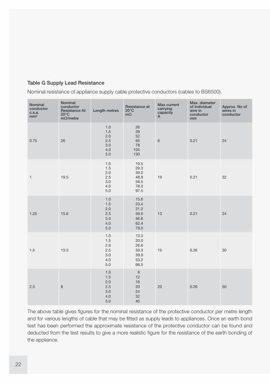
Table G Supply Lead Resistance
Nominal resistance of appliance supply cable protective conductors (cables to BS6500).
The above table gives figures for the nominal resistance of the protective conductor per metre lengthand for various lengths of cable that may be fitted as supply leads to appliances. Once an earth bondtest has been performed the approximate resistance of the protective conductor can be found anddeducted from the test results to give a more realistic figure for the resistance of the earth bonding ofthe appliance.

Experts in what we do.
23
Appendix
HSE Guidance Notes
HSG13 Electrical Testing
HSG107 Maintaining Portable Electrical Equipment
HSR18 Administrative guidance on the application of the EC ‘Low Voltage Directive’
HSR25 Memorandum of guidance on the Electricity at Work Regulations 1989
PM29 Electrical hazards from steam/water pressure cleaners
PM32 The safe use of portable electrical apparatus
PM38 Selection and use of portable electric handlamps
GS27 Protection against electric shock
GS37 Flexible leads, plugs and sockets.
Codes of Practice
IET Code of Practice for In-service Inspection and Testing of ElectricalEquipment 4th Edition ISBN 978-1-84919-626-0
Hire Association of Europe (HAE) and Event Hire Association (EHA)document, ‘Guidance on Electrical Safety Testing in the Hire Industry’ HAEEST2012
Legislation
The Health and Safety at Work etc. Act 1974 ISBN 0 10 5437743
The Electricity at Work Regulations 1989 (S.I.1989 No 635) ISBN 0 11 096635X
The Plugs and Sockets etc. (Safety) Regulations 1987 (S.I.1987 No.603) ISBN 0 11 076603
Contains public sector information licensed under the Open Government Licence v2.0 -http://www.nationalarchives.gov.uk/doc/open-government-licence/version/2/

24
PAT testers fromSeaward
For supreme data management and proof of
visual inspection, Apollo 600 is the only PAT
tester to incorporate an on-board digital camera,
allowing time and date stamped visual evidence
of inspections to be recorded alongside test data
and risk assessment for complete traceability.
Apollo 600 offers a superior range of electrical
safety tests including point to point. It also
provides the ability to carry out risk assessments
for any workplace hazard and complete reports
and certificates for non-electrical test and
inspections including fire detection and
emergency lighting.
Apollo Series. Change the way you work
PAT tester: Full suite of advancedelectrical safety tests
Risk assessment: For both electricaland universal workplace hazards
On-board camera: Visual evidence totag against records
Health & safety forms: Generatesreports and certificates via PATGuard 3Software
Apollo 600, the only PATtester with onboard camera

Experts in what we do.
25
Apollo 500 offers fast and efficient electrical
safety testing with secure and complete data
management. Designed to enable simple,
professional and fast PAT testing the Apollo 500
features point-to-point testing, remote data
transfer, USB upload/download, risk-based retest
calculator and a memory to store up to 10,000
complete test sets.
It’s light weight, small size, battery or mains
power modes, fast boot up and power
scavenging features mean it’s good to go in
seconds. Apollo 500 is the ideal companion for
high-volume testing to the 4th Edition Code of
Practice.
Apollo Series. Change the way you work
PAT tester: Full suite of advancedelectrical safety tests
Risk assessment: For both electricaland universal workplace hazards
On-board camera: Visual evidence totag against records
Health & safety forms: Generatesreports and certificates via PATGuard 3Software
Plug ‘n’ Play
Point to Pointtesting
PATGuard 3compatible
Electrical RiskAssessment
Apollo 500, a great value‘plug and play’ PAT tester

26
ToughRugged enclosure can withstand theharshest of environments
Dual voltageTrue dual voltage for testing both 230V &110V appliances, whether the tester ispowered by a 230v or 110v supply
ReliableProven to be extremely reliable, accurateand hardworking
Primetest 250+
Handheld, compact and featurepacked to testmostworkplaceappliances
Accurate and reliable earth continuity testingFeatures Seaward’s unique zap circuit (patentpending). Go to www.seaward.co.uk/zap-circuitfor more information
Simple data managementStore up to 999 test records and downloadto a PC with a single key press
Plug and printPrint pass and fail labels to the Test n Tag Proprinter via serial cable with no setup
Acomprehensivedual voltagePATwith flash test
SupernovaElite

27
Experts in what we do.
Handheld unit for testing earth continuity,insulation resistance and substitute leakage
Accurate and reliable earth continuity testingFeatures Seaward’s unique zap circuit (patentpending). Go to www.seaward.co.uk/zap-circuitfor more information
Handheld and battery poweredThis lightweight tester is extremely portable
Long battery lifeConducts up to 5000 tests before battery requiresreplacing
Primetest 100
Primetest 50BasicPass/Fail handheldunit for testingearthcontinuity and insulation resistanceof appliances.
Simple to useEasy to use push button operation
Accurate and reliable earth continuity testingFeatures Seaward’s unique zap circuit (patentpending). Go to www.seaward.co.uk/zap-circuitfor more information
Handheld and battery poweredThis lightweight tester is extremely portable

28
This intuitive software program enables you to record, store and report on a range of health and safety
requirements, including PAT testing, risk assessments and other workplace tests and inspections. It’s
also useful for tagging records with images as visual evidence, scheduling retest periods and producing
professional reports and certificates for total traceability. PATGuard 3 is compatible with a wide range
of portable appliance testers, including Seaward’s Apollo series, and offers secure data management
with access control.
Comprehensive PAT Records
Offers total traceability when it comes to maintaining PAT records, enabling images taken with Apollo
600, or any camera/phone, to be tagged against sites, locations, asset IDs and test results – providing
evidence of visual inspection. Tagged images can be included in the vast range of
detailed reports that can be created. These are easily stored, printed or emailed.
A Risk-based Approach
The built in electrical risk assessment tool can be used to ensure a risk-based
approach is taken to PAT testing; automatically determining retest periods
proportionate to risk for assets as required by the IET Code of Practice. The
universal risk assessment tool means that it has never been simpler to record details
of any workplace hazard, calculate risk scores and schedule corrective actions.
Complete Health and Safety Management
A range of additional health and safety test and inspection certificates are built
into PATGuard 3, allowing records for the inspection of emergency lighting and
fire alarm systems to be kept and easily managed. The software program is
upgradeable to include more health and safety reports and certificates as updates
are released.
Tag & Recordphotographs
RiskAssessment
H&S Reporting& Certification
PAT RecordManagement
PATGuard 3

29
Simple Asset Management
PATGuard 3 features a simple checkbox system to help you keep track of
assets which are in service. It is also easy to keep asset repair and
maintenance records, including any associated costs where applicable.
The ability to tag images next to asset records has an added benefit of aiding
quick and easy identification of appliances and equipment to make life simpler
when it comes to retesting.
Compatible with Apollo Series
PATGuard 3 is the ultimate companion for the Apollo Series, a total safety
management tool. When used with Apollo 600 it is simple to upload and
download reports, images, test results and risk assessments to and from
the tester via Bluetooth or USB connectivity. As well as being compatible
with all Seaward PAT testers, PATGuard 3 is also suitable to use with a range
of other manufacturers’ testers.
Security and Traceability Assured
PATGuard 3 offers a secure and non-editable record system ensuring that records downloaded from
your tester cannot be changed at a later date; this ensures complete security and integrity of test data.
In addition, user accounts can be set up with varying access levels, including a read-only view if required.
For full details of how this intuitive software will revolutionise your productivity and to download a free
trial visit: www.seaward.co.uk/pg3trial
Experts in what we do.
PATGuard 3 Elite PATGuard 3 Elements
Premier edition. Features allfunctionality detailed above
Manual data entry edition. Features all functionality detailedfor PATGuard 3 Elite, except those related to compatibilitywith downloadable testers.
Compatible with: Apollo 600 Apollo 500 Supernova Elite Primetest 250+
Compatible with: PrimeTest 100 PrimeTest 50 Any non-downloading tester

Printers and ScannersA selection of tough and portable label printers interact with Seaward testers to enable direct printing of assetinformation or test results to label in no time. The barcode scanners also aid faster testing when used inconjunction with a compatible tester.
Test n Tag Elite printerRobust and compact, connects via Bluetooth to theApollo series testers.
Part No: 339A980
Test n Tag Pro printerLightweight and compact, connects via Bluetoothto the Apollo series testers or serial cable to PT250+.Bluetooth model Part No: 339A970Serial only model Part No: 339A933
Bluetooth scannerIdeal for use with the Apollo series, fast and compactlabel scanning.
Part No: 339A923
Test n Tag Elite printer labelsThermal label with resistant finish.
Label roll (approx. 180 off 52 x 74mm labels)Part no. 339A041Label roll without perforations (approx. 160 off52 x 74mm labels) Part no. 339A944
Test n Tag Pro printer labelsThermal label with resistant finish.
Label roll (approx. 160 off 52 x 74mm labels)Part no. 339A944 (not compatible when usingPrimeTest 250+) Label roll (approx. 400 off 52 x25mm labels) Part no. 339A945
CCD scannerInput and access data quickly into Supernova Elite.
Part No: 194A922
30

PAT Testing LabelsFor all your replacement labels, Seawards supplies a variety to suit any requirement.
Leads and AdaptorsTesting different types of workplace appliances may mean that different leads and adaptors are required.
Verification UnitsUse a Seaward verification unit to carry out performance checks between periodic calibration of your tester.
1000 x PASS labelsPaper labels for visual identification that an electricalappliance has passed the relevant electricalsafety tests.
Part No: 91B038
1000 x FAIL labelsThese high visibility labels are designed for use on itemsthat have failed the PAT test (ie. formal visual inspectionand / or electrical safety tests).
Part No: 91B311
100 x RhinotagsAlmost indestructible, ideal for use in demandingenvironments.
Part No: 91B309
250 x Barcode appliance no. labelsPrinted white labels containing an individual appliancenumber and barcode used for marking appliances.
Part No: 194A307
PowerCheckSuitable for verifying PATand installation testers.
Part No: 369A910
NTB-1 RCD isolatorPrevents tripping the main RCDduring RCD trip time tests using the PrimeTest 250.
Part No: 372A953
TPA Series 3 Phase leakage and earthcontinuity adaptorEnables leakage testing on 3 phase machinery,plant and equipment.
16A Part No: 391A92032A Part No: 391A910
3 Phase adaptorsAvailable in 16 & 32 Amp and 4 or 5 pin Configuration.Allows earth continuity and insulation resistancemeasurements to be made on 3 phase equipment usingPAT testers with a standard UK 240V test socket.16A 4 Pin Part No: 209A91016A 5 Pin Part No: 209A91132A 4 Pin Part No: 209A91232A 5 Pin Part No: 209A913
PAT checkboxA safe and simple way tocheck your PAT tester.
Part No: 227A910
230/110V adaptorAllows earth continuity and insulation resistancemeasurements to be made on 110V equipment.
Supernova Specific Part No: 281A075All other models: 270A076
31

32
Seaward Group provides electrical test and measurement instruments and services. Our products meet
the demands of all types of safety legislation and standards. We are an international market leader in
a number of highly technical market sectors. We pride ourselves on high quality product design and
manufacturing.
We believe in putting you, the international customer, at the heart of everything we do. Our multi-lingual
customer services department, overseas technical support centres and global distribution network all
help us to excel.
Rigel Medical, a Seaward Group company, currently holds The Queen’s Award for Enterprise, one of
the most prestigious awards that a UK-based company can achieve.
World LeadingElectricalTest Solutions
Seaward Clare Cropico Rigel Solar Calibrationhouse
PAT, installation andhigh voltage testand measurement
solutions
www.seaward.co.uk
Test solutionsfor electrical
manufacturers andhire companies
www.clare.co.uk
High precisionresistance andtemperaturemeasurementinstruments
www.cropico.com
Advanced solutionsfor testing biomedical
equipment
www.rigelmedical.com
Safe, efficienttest solutions for PV
installers
www.seawardsolar.com
Taking care of your testand measurement
equipment
www.calibrationhouse.com
Our six brands operate to the same high standards; innovating and enhancing electricalsafety testing in their individual markets.
www.seaward-group.com
TrainingWe offer a number of training courses designed to support those in the PAT testing industry,some of which are City & Guilds approved. We also offer product training to ensure you get themost out of your Seaward product.
www.seaward.co.uk/training

Visit www.seaward.co.uk or call +44 (0)191 587 8741Follow us on Twitter: @SeawardPAT
Introducing the all new PrimeTest 250+ from Seaward.The most compact and easy to use fully featured PAT tester. With data storage,downloading and direct label printing. No setup required for faster and easier testing.
ResultA no-setup, PAT testerwith results downloading
as standard
The all new PrimeTest 250+
FREEData Logger
Softwareincluded

Seaward, Bracken Hill, South West Industrial Estate,Peterlee, County Durham, SR8 2SW United Kingdom
Tel: +44 (0) 191 586 3511 Fax: +44 (0) 191 586 0227Email: [email protected] Web: www.seaward.co.uk
l@SeawardPAT iFind Seaward Group on Linkedin
Rev 4.2
Copyright © 2014 Seaward Electronic Ltd.
RRP £20