Embed Size (px)
Citation preview

8/6/2019 se lab filw
http://slidepdf.com/reader/full/se-lab-filw 1/8
INTRODUCTION TO RATIONAL ROSE
Rational Machines was founded by Paul Levy and Mike Devlin in 1981 to provide tools to
expand the use of modern software engineering practices, particularly explicit modular
architecture and iterative development. Rational was sold for US$2.1 billion to IBM on
February 20, 2003.
Rational Rose is an object-oriented Unified Modeling Language (UML) software design tool
intended for visual modeling and component construction of enterprise-level software
applications. In much the same way a theatrical director blocks out a play, a software
designer uses Rational Rose to visually create (model) the framework for an application by
blocking out classes with actors (stick figures), use case elements (ovals), objects (rectangles)
and messages/relationships (arrows) in a sequence diagram using drag-and-drop symbols.
Rational Rose documents the diagram as it is being constructed and then generates code in
the designer's choice of C++, Visual Basic, Java, Oracle8, Corba or Data Definition
Language.
Two popular features of Rational Rose are its ability to provide iterative development and
round-trip engineering. Rational Rose allows designers to take advantage of iterative
development (sometimes called evolutionary development) because the new application can
be created in stages with the output of one iteration becoming the input to the next. (This is in
contrast to waterfall development where the whole project is completed from start to finish
before a user gets to try it out.) Then, as the developer begins to understand how the
components interact and makes modifications in the design, Rational Rose can perform what
is called "round-trip engineering" by going back and updating the rest of the model to ensure
the code remains consistent.
Rational Rose is extensible, with downloadable add-ins and third-party partner applications.
It supports COM/DCOM (ActiveX), JavaBeans, and Corba component standards.

8/6/2019 se lab filw
http://slidepdf.com/reader/full/se-lab-filw 2/8
INTRODUCTION TO USE CASE DIAGRAM
A use case diagram in the Unified Modeling Language (UML) is a type of behavioral
diagram defined by and created from a Use-case analysis. Its purpose is to present a graphical
overview of the functionality provided by a system in terms of actors, their goals (represented
as use cases), and any dependencies between those use cases.
The main purpose of a use case diagram is to show what system functions are performed for
which actor. Roles of the actors in the system can be depicted.
Diagram Building Blocks
Interaction among actors is not shown on the use case diagram. If this interaction is essential
to a coherent description of the desired behavior, perhaps the system or use case boundaries
should be re-examined. Alternatively, interaction among actors can be part of theassumptions used in the use case.
Use cases
A use case describes a sequence of actions that provide something of measurable value to an
actor and is drawn as a horizontal ellipse.
Actors
An actor is a person, organization, or external system that plays a role in one or more
interactions with the system.
System boundary boxes (optional)
A rectangle is drawn around the use cases, called the system boundary box, to indicate the
scope of system. Anything within the box represents functionality that is in scope and
anything outside the box is not.
Actor Generalization
One popular relationship between Actors is Generalization/Specialization. This is useful in
defining overlapping roles between actors. The notation is a solid line ending in a hollow
triangle drawn from the specialized to the more general actor.
8/6/2019 se lab filw
http://slidepdf.com/reader/full/se-lab-filw 3/8
Use Case Relationships
Four relationships among use cases are used often in practice.
Include
In one form of interaction, a given use case may include another. "Include is a Directed
Relationship between two use cases, implying that the behavior of the included use case is
inserted into the behavior of the including use case".
The first use case often depends on the outcome of the included use case. This is useful for
extracting truly common behaviors from multiple use cases into a single description. The
notation is a dashed arrow from the including to the included use case, with the label"«include»". This usage resembles a macro expansion where the included use case behavior
is placed inline in the base use case behavior. There are no parameters or return values. To
specify the location in a flow of events in which the base use case includes the behavior of
another, you simply write include followed by the name of use case you want to include.
Extend
In another form of interaction, a given use case (the extension) mayextend another. The
relationship indicates that the behavior of the extension use case may be inserted in the
extended use case under some conditions. The notation is a dashed arrow from the extension
to the extended use case, with the label "«extend»". The notes or constraints may beassociated with this relationship to illustrate the conditions under which this behavior will be
executed.
Modelers use the «extend» relationship to indicate use cases that are "optional" to the base
use case. Depending on the modeler's approach "optional" may mean "potentially not
executed with the base use case" or it may mean "not required to achieve the base use case
goal".
Generalization
In the third form of relationship among use cases, a generalization/specialization relationshipexists. A given use case may have common behaviors, requirements, constraints, and
assumptions with a more general use case. In this case, describe them once, and deal with it
in the same way, describing any differences in the specialized cases. The notation is a solid
line ending in a hollow triangle drawn from the specialized to the more general use case
(following the standard generalization notation)

8/6/2019 se lab filw
http://slidepdf.com/reader/full/se-lab-filw 4/8
Associations
Associations between actors and use cases are indicated in use case diagrams by solid lines.
An association exists whenever an actor is involved with an interaction described by a use
case. Associations are modeled as lines connecting use cases and actors to one another, with
an optional arrowhead on one end of the line. The arrowhead is often used to indicate thedirection of the initial invocation of the relationship or to indicate the primary actor within
the use case. The arrowheads imply control flow and should not be confused with data flow.

8/6/2019 se lab filw
http://slidepdf.com/reader/full/se-lab-filw 5/8
EXPE E T 1
________________________________________________________________
:To
draw use case diagram f o
r R egistration
system.
DIAGRAM:
The use case diagram f or the registration system is:

8/6/2019 se lab filw
http://slidepdf.com/reader/full/se-lab-filw 6/8
DISCUSSION
In the use case diagram for the registration system we have two actors student and faculty .
Actor student has four use cases login ,fill details,print and submit. Now the login further
extends to two use cases user id and password.Fill details also extends to the use cases fill
name ,fill address,fill place of stay during the year ,fill phone number and save .Print has the
use case print preview as it includes from print on clicking print preview new window
opens.The actor faculty has the use case receive ,verify and the use case submit is common
between the two actors student and faculty. Use cases receive and verify has fee receipt
,registration form and affadavits as common use cases. Associations between actors and use
cases are indicated in use case diagrams by solid lines with an arrow head. Associations of
the use cases with the further use cases are indicated by dotted lines with an arrow head.
8/6/2019 se lab filw
http://slidepdf.com/reader/full/se-lab-filw 7/8
E ERIMENT 2
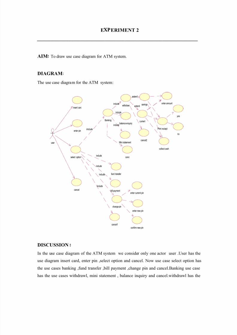
AIM To draw use case diagram for ATM system.
DIAGRAM
The use case diagram for the ATM system:
DISCUSSION
In the use case diagram of the ATM system we consider only one actor user .User has the
use diagram insert card, enter pin ,select option and cancel. Now use case select option has
the use cases banking ,fund transfer ,bill payment ,change pin and cancel.Banking use case
has the use cases withdrawl, mini statement , balance inquiry and cancel.withdrawl has the
insert card
enter pin
select option
user
cancel
Banking
fund transfer
bill payment
change pin
cancel1
withdrawl
balance enquiry
Mini statement
cancl
savings
current
cancel2
enter amount
Print reciept
yes
no
collect cash
imclude
include
include
include
include
enter current pin
enter new pin
confirm new pin
include
include
include
extend
extend

8/6/2019 se lab filw
http://slidepdf.com/reader/full/se-lab-filw 8/8
use cases savings ,current and cancel .Now saving and current has the same use cases enter
amount ,print receipt and collect cash . Further print receipt has two use cases yes and no.
There is a use case change pin has three use cases enter current pin,enter new pin and confirm
new pin . Associations between actors and use cases are indicated in use case diagrams by
solid lines with an arrow head. Associations of the use cases with the further use cases are
indicated by dotted lines with an arrow head