Embed Size (px)
DESCRIPTION
https://www.google.ae/search?newwindow=1&hl=ar&biw=1360&bih=623&tbm=isch&sa=1&q=experiment+to+steam+dryness+fraction+measurement&oq=experiment+to+steam+dryness+fraction+measurement&gs_l=img.12...0.0.0.679985.0.0.0.0.0.0.0.0..0.0....0...1c..64.img..0.0.0.yvKz0Ndm6IY#imgrc=MxxCp02UvWiARM%3A
Citation preview
LABORATORY MANUAL
ENGINEERING THERMODYNAMICS
(ME-203)
DEPARTMENT OF MECHANICAL ENGINEERING
MGM’S
JAWAHARLAL NEHRU ENGINEERING COLLEGE
N-6, CIDCO, AURANGABAD-431003
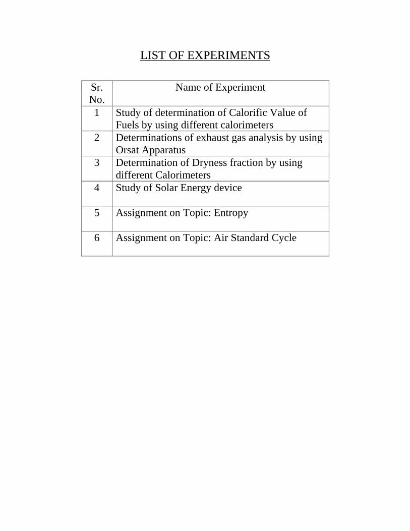
LIST OF EXPERIMENTS
Sr.
No.
Name of Experiment
1 Study of determination of Calorific Value of
Fuels by using different calorimeters
2 Determinations of exhaust gas analysis by using
Orsat Apparatus
3 Determination of Dryness fraction by using
different Calorimeters
4 Study of Solar Energy device
5 Assignment on Topic: Entropy
6 Assignment on Topic: Air Standard Cycle
EXPERIMENT NO. 1
Study of determination of Calorific Value of Fuels by using different calorimeters
Aim: - A. To study determination of Calorific Value of Fuels by using Bomb calorimeter.
Apparatus: - Bomb Calorimeter
Theory:-
The “calorific value or heating value” of the fuel is defined as the energy liberated
by the complete oxidation of a unit mass or volume of a fuel. It is expressed in kJ/kg for
solid and liquid fuels and kJ/m3 for gases.
The higher heating value, HHV, is obtained when the water formed by
combustion is completely condensed.
The lower heating value, LHV, is obtained when the water formed by combustion
exists completely in the vapour phase.
Bomb calorimeter:
The calorific value of solid and liquid fuels is determined in the laboratory by
‘Bomb calorimeter’.
It is so named because its shape resembles that of a bomb. Fig. 1 shows the
schematic sketch of a bomb calorimeter.
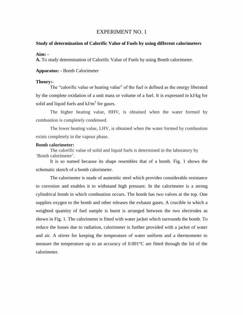
The calorimeter is made of austenitic steel which provides considerable resistance
to corrosion and enables it to withstand high pressure. In the calorimeter is a strong
cylindrical bomb in which combustion occurs. The bomb has two valves at the top. One
supplies oxygen to the bomb and other releases the exhaust gases. A crucible in which a
weighted quantity of fuel sample is burnt is arranged between the two electrodes as
shown in Fig. 1. The calorimeter is fitted with water jacket which surrounds the bomb. To
reduce the losses due to radiation, calorimeter is further provided with a jacket of water
and air. A stirrer for keeping the temperature of water uniform and a thermometer to
measure the temperature up to an accuracy of 0.001°C are fitted through the lid of the
calorimeter.
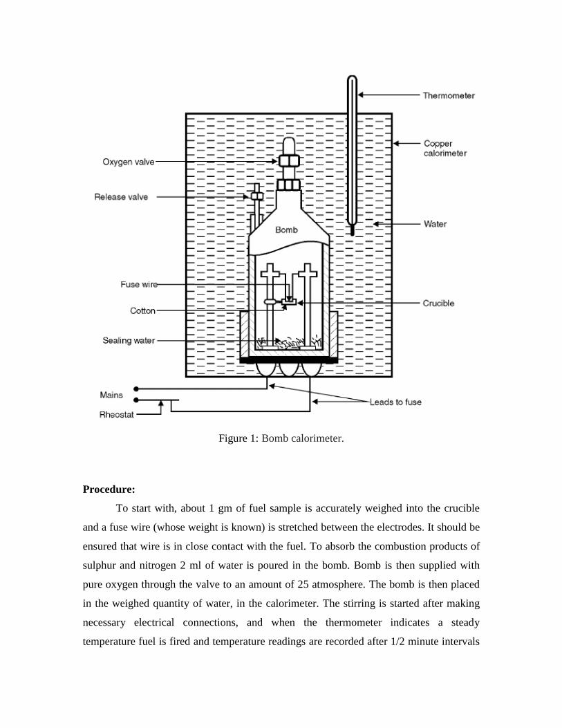
Figure 1: Bomb calorimeter.
Procedure:
To start with, about 1 gm of fuel sample is accurately weighed into the crucible
and a fuse wire (whose weight is known) is stretched between the electrodes. It should be
ensured that wire is in close contact with the fuel. To absorb the combustion products of
sulphur and nitrogen 2 ml of water is poured in the bomb. Bomb is then supplied with
pure oxygen through the valve to an amount of 25 atmosphere. The bomb is then placed
in the weighed quantity of water, in the calorimeter. The stirring is started after making
necessary electrical connections, and when the thermometer indicates a steady
temperature fuel is fired and temperature readings are recorded after 1/2 minute intervals
until maximum temperature is attained. The bomb is then removed; the pressure slowly
released through the exhaust valve and the contents of the bomb are carefully weighed for
further analysis.
The heat released by the fuel on combustion is absorbed by the surrounding water
and the calorimeter.
From the above data the calorific value of the fuel can be found in the following way:
Let Wf = Weight of fuel sample (kg),
W = Weight of water (kg),
C = Calorific value (higher) of the fuel (kJ/kg),
We = Water equivalent of calorimeter (kg),
T1 = Initial temperature of water and calorimeter,
T2 = Final temperature of water and calorimeter,
Tc = Radiation corrections, and
c = Specific heat of water.
Heat released by the fuel sample = Wf × C
Heat received by water and calorimeter
= (Ww + We) × c × [(T2 – T1) + Tc].
Heat lost = Heat gained
Wf × C = (W + We) × c × [(T2 + T1) + Tc]
i.e., 2 1( ) [( ) ]e c
f
W W c T T TC
W
[Value of c is 4.18 in SI units and unity in MKS units.]
Note:
1. Corrections pertain to the heat of oxidation of fuse wire, heat liberated as a result of
formation of sulphuric and nitric acids in the bomb itself.
2. It should be noted that bomb calorimeter measures the higher or gross calorific value
because the fuel sample is burnt at a constant volume in the bomb. Further the bomb
calorimeter will measure the H.C.V. directly if the bomb contains adequate amount of
water before firing to saturate the oxygen. Any water formed from combustion of

hydrogen will, therefore, be condensed. The procedure of determining calorific values of
liquid fuels is similar to that described above. However, if the liquid fuel sample is
volatile, it is weighed in a glass bulb and broken in a tray just before the bomb is closed.
In this way the loss of volatile constituents of fuels during weighing operation is
prevented.
Aim: -
B. To study determination of Calorific Value of Fuels by using
Boys Gas calorimeter.
Apparatus: - Boys Gas Calorimeter
Theory:-
This calorimeter is suitable for determination of calorific value of gaseous fuels.
Figure 2 shows the components of the Boys gas calorimeter. It consists of a gas burner B
with arrangement to measure flow quantity and pressure of the gas supplied to the burner.
A gas pressure regulator is used in the gas supply line to damp down any pressure
fluctuations which would affect the results adversely. The fuel supplied burns within a
cylindrical container which is surrounded by a cooling coil from a constant head tank.
The flue gas moves up in the cylindrical container and then it flows down from the top of
the container as shows in the figure. The steam formed due to the combustion of
hydrogen in the fuel and carried with the gases condenses around the cooling coil and
drips down into the trap below as shown in the figure. The overflow of the condensate is
taken out in a glass beaker as shown in the figure.
Figure 2: Boys gas calorimeter
The outer casing of the calorimeter is provided with heavy insulation to prevent any heat
loss to the surrounding:
The following readings are taken during the test:
1. Time of run
2. Pressure and temperature of the gas supply
3. Volume of gas consumed
4. Mass of water circulated
5. Rise in temperature of water
6. Mass of condensate collected
7. Barometric reading
From the above readings, the calorific value of the gas is calculated as follows:
V’g = Volume of gas consumed in m3
mw = Mass of water circulated in kg
(∆T)w= Rise in temperature of water circulated.
Pressure of the gas= hw cm of water above the atmosphere,
Barometer reading= hb cm of Hg.
Temperature of the gas supply= Tg
Vg = Volume of gas supplied
If the volume of gas supplied is converted to N.T.P. conditions, then the volume of gas at
N.T.P. is given by
Vg= Vg’ X 273/Tg X (hb+hw/12.6)/760 --------------- (1)
The calorific value of the fuel is given by
Vg X H.C.V. = mw(∆T)w
Therefore,
H.C.V. = mw (∆T)w/Vg kj/m3 atv N.T.P. --------------------(2)
RESULT: Hence we study the Boys gas calorimeter for determination of calorific value
of gaseous fuel.
Note: In calculating the calorific value, it is assumed that the flue gas temperature at the
calorimeter exit is equal to the air temperature entering in to the calorimeter.
The equation (2) gives the H.C.V. of the fuel as the H2O vapour formed due to the
burning of H2 in fuel is condensed and collected.
For finding L.C.V. the heat carried by H2O should be deducted from the H.C.V.
EXPERIMENT NO. 2
Determinations of exhaust gas analysis by using Orsat Apparatus
Aim: - Determination of exhaust gas analysis by using Orsat apparatus.
Apparatus: - Orsat apparatus
Theory:-
The combustion products are mainly gaseous. When a sample is taken for analysis
it is usually cooled down to a temperature which is below the saturation temperature of
the steam present. The steam content is therefore not included in the analysis, which is
then quoted as the analysis of the dry products. Since the products are gaseous, it is usual
to quote the analysis by volume. An analysis which includes the steam in the exhaust is
called a wet analysis.
Practical analysis of combustion products:
The most common means of analysis of the combustion products is the Orsat apparatus
which is described below:
Construction: An Orsat’s apparatus consists of the following:
(i) A burette
(ii) A gas cleaner
(iii) Four absorption pipettes 1, 2, 3, 4.
The pipettes are interconnected by means of a manifold fitted with cocks S1, S2, S3 and
S4 and contain different chemicals to absorb carbon dioxide (CO2), carbon monoxide
(CO) and oxygen (O2). Each pipette is also fitted with a number of small glass tubes
which provide a greater amount of surface. These tubes are wetted by the absorbing
agents and are exposed to the gas under analysis. The measuring burrette is surrounded
by a water jacket to prevent, changes in temperature and density of the gas. The pipettes
1, 2, 3, 4 contain the following chemicals:
Pipette 1: Contains ‘KOH’ (caustic soda) to absorb CO2 (carbon dioxide)
Pipette 2: Contains an alkaline solution of ‘pyrogallic acid’ to absorb O2 (oxygen)
Pipette 3, 4 : Contain an acid solution of ‘cuprous chloride’ to absorb CO (carbon
monoxide) Furthermore the apparatus has a levelling bottle and a three way cock to
connect the apparatus either to gases or to atmosphere.
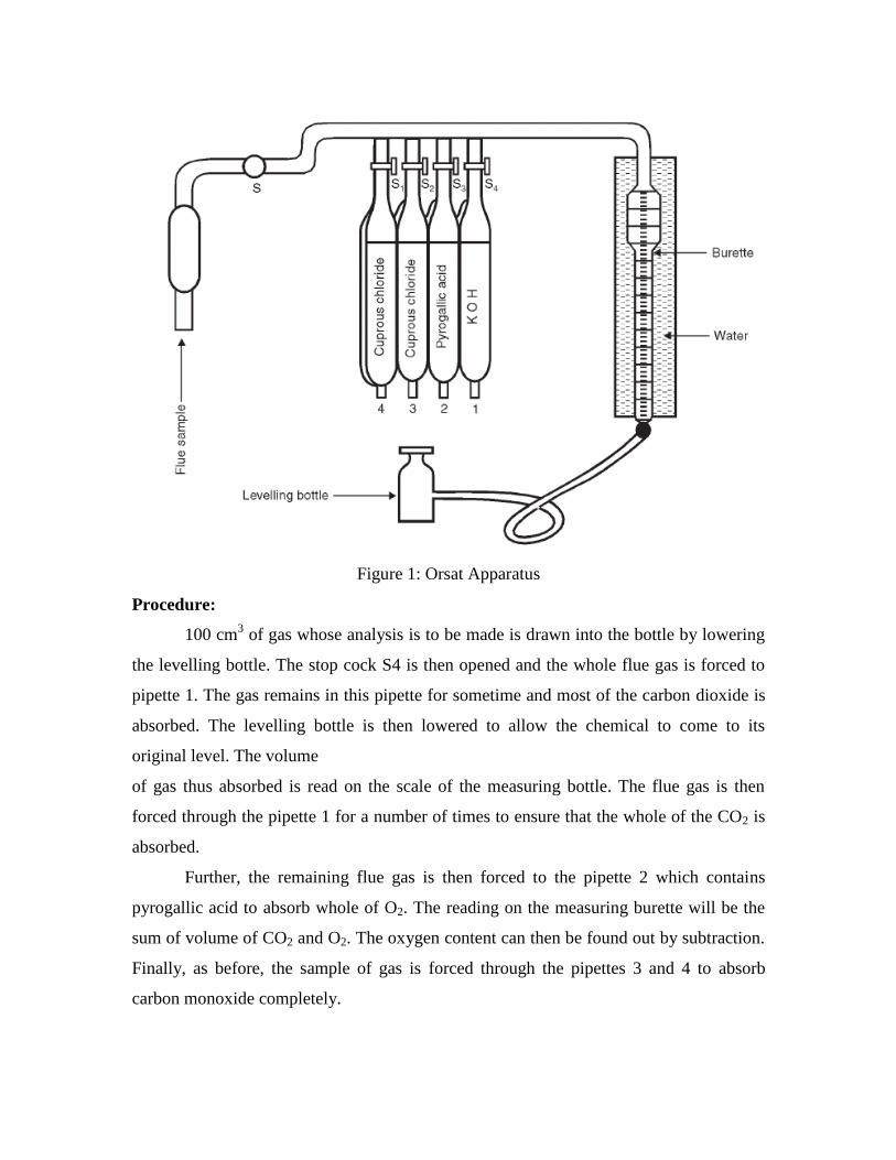
Figure 1: Orsat Apparatus
Procedure:
100 cm3 of gas whose analysis is to be made is drawn into the bottle by lowering
the levelling bottle. The stop cock S4 is then opened and the whole flue gas is forced to
pipette 1. The gas remains in this pipette for sometime and most of the carbon dioxide is
absorbed. The levelling bottle is then lowered to allow the chemical to come to its
original level. The volume
of gas thus absorbed is read on the scale of the measuring bottle. The flue gas is then
forced through the pipette 1 for a number of times to ensure that the whole of the CO2 is
absorbed.
Further, the remaining flue gas is then forced to the pipette 2 which contains
pyrogallic acid to absorb whole of O2. The reading on the measuring burette will be the
sum of volume of CO2 and O2. The oxygen content can then be found out by subtraction.
Finally, as before, the sample of gas is forced through the pipettes 3 and 4 to absorb
carbon monoxide completely.
The amount of nitrogen in the sample can be determined by subtracting from total
volume of gas the sum of CO2, CO and O2contents. Orsat apparatus gives an analysis of
the dry products of combustion. Steps may have been taken to remove the steam from the
sample by condensing, but as the sample is collected over water it becomes saturated
with water. The resulting analysis is nevertheless a true analysis of the dry products. This
is because the volume readings are taken at a constant temperature and pressure, and the
partial pressure of the vapour is constant. This means that the sum of the partial pressures
of the remaining constituents is constant. The vapour then occupies the same proportion
of the total volume at each measurement. Hence the vapour does not affect the result of
the analysis.
RESULT: Hence we studied the Orsat apparatus for analysis of flue gases.
Note:
Quantitatively the dry product analysis can be used to calculate A/F ratio. This
method of obtaining the A/F ratio is not so reliable as direct measurement of air
consumption and fuel consumption of the engine. More caution is required when
analysing the products of consumption of a solid fuel since some of the products do not
appear in the flue gases (e.g. ash and unburnt carbon). The residual solid must be
analysed as well in order to determine the carbon content, if any. With an engine using
petrol or diesel fuel the exhaust may include unburnt particles of carbon and this quantity
will not appear in the analysis. The exhaust from internal combustion engines may
contain also some CH4 and H2 due to incomplete combustion. Another piece of
equipment called the Heldane apparatus measures the CH4 content as well as CO2, O2and
CO.
EXPERIMENT NO. 3
Determination of Dryness fraction by using different Calorimeters
Aim: - To determine dryness fraction of steam by using Separating throttling calorimeter
OBJECTIVE:
The objective of this experiment is to study the determination of the dryness
fraction of wet steam by using
1. Tank Calorimeter
2. Separating Calorimeter
3. Throttling Calorimeter
4. Separating and Throttling Calorimeter
THEORY:
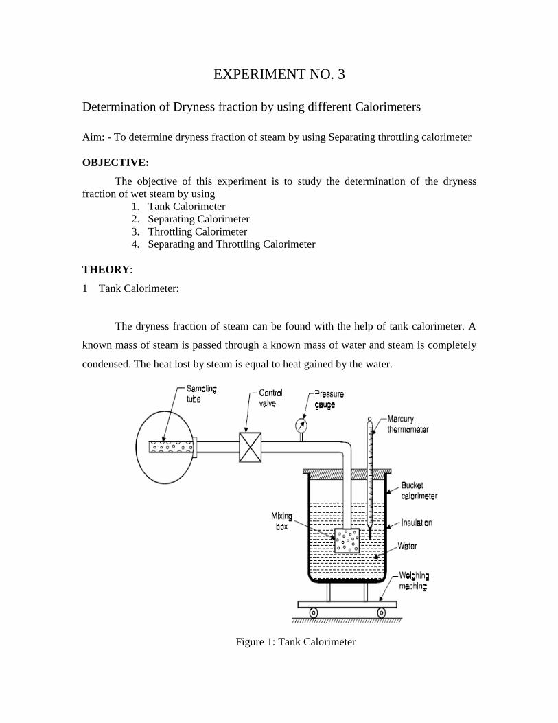
1 Tank Calorimeter:
The dryness fraction of steam can be found with the help of tank calorimeter. A
known mass of steam is passed through a known mass of water and steam is completely
condensed. The heat lost by steam is equal to heat gained by the water.
Figure 1: Tank Calorimeter
The arrangement of this calorimeter is shown in figure. The steam is passed
through the sample tube in to the bucket calorimeter containing a known mass of water.
The weight of calorimeter with water before mixing the steam and after mixing the steam
is obtained by weighing. The temperature of water before and after mixing the steam is
measured by mercury thermometer. The pressure of steam passed through the sample
tube is measured with the help of pressure gauge.
Ps= gauge pressure of steam (KPa)
Pa= atmospheric pressure (KPa)
Ts= saturation temperature of steam known from the steam table at pressure
(Ps+Pa)
hfg= latent heat of steam
X= dryness fraction of steam
mc= mass of calorimeter in kg
m1= mass of calorimeter and water in kg
mw= (m1-mc)= mass of water in calorimeter
m2= mass of calorimeter, water and condensed steam
ms= (m2-m1)= mass of steam condensed in calorimeter in kg
T1= Temperature of water and calorimeter before mixing the steam in oC
T2= Temperature of water and calorimeter after mixing the steam in oC
Neglecting the losses and assuming the heat lost by steam is gained by the water
and calorimeter, we can write
2 1 2 1 2 2 1 2 1fg g pw c pcm m xh T T m m C T T m C T T
Where Cpw and Cpc are the specific heats of water and calorimeter respectively.
2 2 1 1 2 1s fg s c pw c pcm xh T T T T m m C m C T T
2 1 2pw w pc c s s
s fg
C m C m T T m T Tx
m h
The mcCpc is known as water equivalent of calorimeter.
NOTE:- As the losses due to convection and radiation are not taken into account, the
dryness fraction determined involves some inaccuracy. The calculated value of dryness
fraction neglecting losses is always less than the actual value of the dryness.
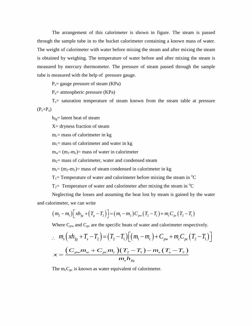
2 Separating Calorimeter
This calorimeter is used to measure the probable value of dryness fraction of steam
when the steam is very wet.
The arrangement of the calorimeter is shown in figure. The steam is passed through a
sample tube as shown in the figure. The moisture is separated mechanically from the
steam. The steam is passed through perforated trays and water partials are separated due
to inertia of the droplets. The outgoing steam is condensed in the bucket calorimeter.
Figure 2: Separating Calorimeter
mw= mass of water separated from the steam
ms= mass of steam condensed in the bucket calorimeter which can be calculated by the
difference in mass of the bucket calorimeter before and after mixing the steam.
X= dryness fraction of steam.
Therefore,
s
s w
mx
m m
In calculating the dryness fraction of steam by this method it is assumed that all the water
partials are removed in the separating section and the steam entering in the bucket
calorimeter is completely dry.
NOTE:-
In practice, it is not possible to remove all the water particles from the steam by this
mechanical process and, therefore, the dryness fraction obtained by this calorimeter will
not be very accurate. The dryness fraction calculated by this method is always greater
than the actual. The only advantage of this method is the quick determination of the
dryness fraction of a very wet steam.
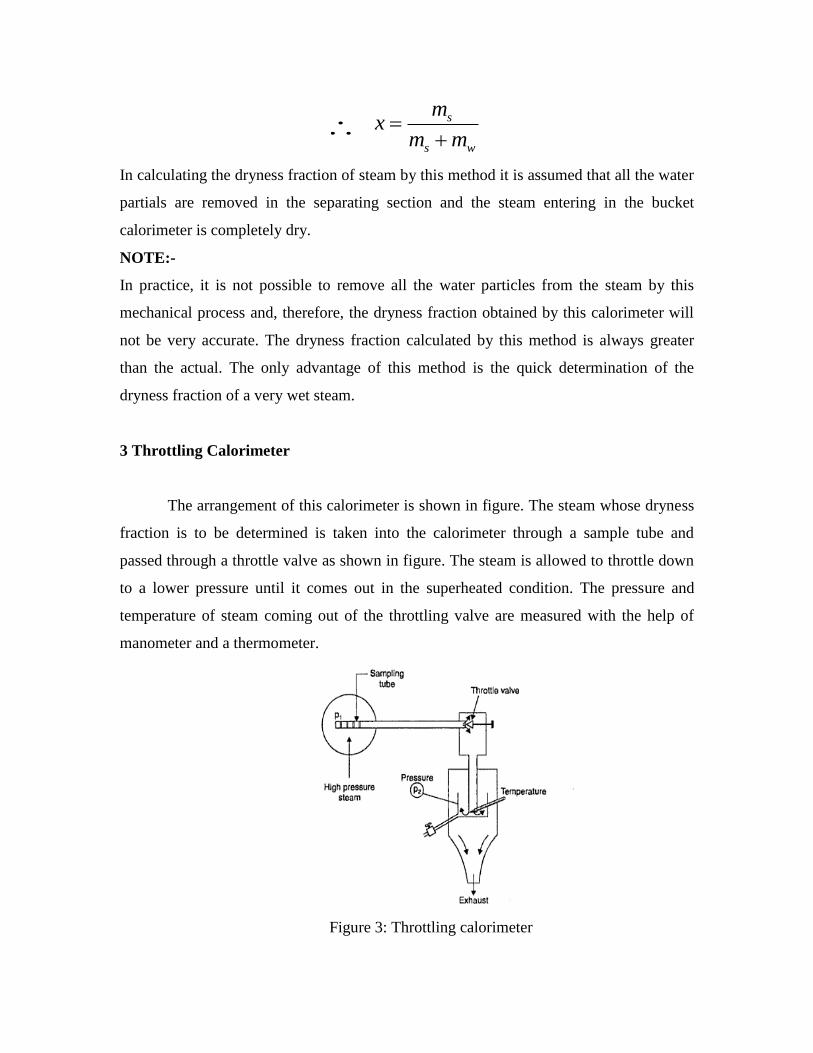
3 Throttling Calorimeter
The arrangement of this calorimeter is shown in figure. The steam whose dryness
fraction is to be determined is taken into the calorimeter through a sample tube and
passed through a throttle valve as shown in figure. The steam is allowed to throttle down
to a lower pressure until it comes out in the superheated condition. The pressure and
temperature of steam coming out of the throttling valve are measured with the help of
manometer and a thermometer.
Figure 3: Throttling calorimeter
P1= gauge pressure of steam in bar
X2= dryness fraction of steam
pa= atmospheric pressure in bar
Ts1= saturation temperature of steam at a pressure of (p1+pa) known from steam tables.
hfg1= latent heat of steam at pressure (p1+pa).
Hw= manometer reading in cm of water above atmospheric pressure.
Therefore,
Absolute pressure of steam after throttling
2
1.03
13.6 76
wa
Hp p
Ts2= saturation temperature of steam at pressure p2
hg2= Enthalpy of saturated steam at pressure p2
Cps= specific heat of superheated steam
Tsup2= temperature of steam after throttling
The enthalpy of steam remains constant during throttling process.
Enthalpy before throttling= Enthalpy after throttling
21 1 1 2 2 sup2 2 2 2pf fg f fg ps s g ps s sh x h h h C T T h C T T
22 2 1
1
1
pg ps s s f
fg
h C T T hx
h
NOTE:-
The condition for the successful operation of this calorimeter is that the steam must be
superheated after throttling. This condition requires a high dryness fraction of the steam
before throttling. This calorimeter cannot be used if the dryness fraction of the steam is
above 0.95. The minimum dryness fraction of the steam that can be measured by
throttling calorimeter depends upon the initial pressure of the steam as the pressure after
throttling virtually remains near atmospheric.
4 Separating and Throttling Calorimeter
The dryness fraction measured with the help of separating calorimeter is always
higher than the actual. This is because of incomplete separation of moisture by
mechanical means.
If the steam is highly wet (0.6 to 0.9), then its dryness fraction cannot be measured, by
throttling calorimeter as it will not become superheated after throttling. Therefore the
dryness fraction of highly wet steam is measured accurately by combining in series
separating and throttling calorimeter.
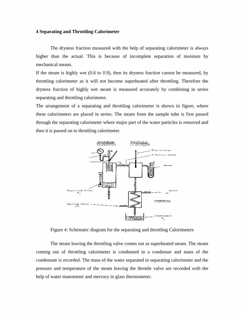
The arrangement of a separating and throttling calorimeter is shown in figure, where
these calorimeters are placed in series. The steam from the sample tube is first passed
through the separating calorimeter where major part of the water particles is removed and
then it is passed on to throttling calorimeter.
Figure 4: Schematic diagram for the separating and throttling Calorimeters
The steam leaving the throttling valve comes out as superheated steam. The steam
coming out of throttling calorimeter is condensed in a condenser and mass of the
condensate is recorded. The mass of the water separated in separating calorimeter and the
pressure and temperature of the steam leaving the throttle valve are recorded with the
help of water manometer and mercury in glass thermometer.
ms= mass of steam condensed and collected from condenser.
mw= mass of water collected from separating calorimeter.
X= actual dryness fraction of steam in main pipe.
X1= apparent dryness fraction of steam measured by separating calorimeter assuming that
the steam coming out of separating calorimeter is completely dry.
X2= actual dryness fraction of steam entering in to the throttling calorimeter.
The apparent dryness fraction is given by
1s
s w
mx
m m
----------------------1
Amount of water carried by the steam before entering into the calorimeter
= 1 s wx m m -----------------------2
Amount of water separated in separating calorimeter
= 11 s wx m m ----------------3
And amount of carried by the steam in in to the throttling calorimeter
= 21 sx m ----------------4
The mass of water in the steam given by the equation (2) must be equal to the quantities
of water given by equations (3) and (4).
1 21 1 1s w s w sx m m x m m x m
1 21 1 1 s
s w
mx x x
m m
But 1
s
s w
mx
m m
Substituting the value in the above equation
1 2 1 1 1 1 21 1 1 1x x x x x x x x
1 2x x x
This calorimeter gives very accurate value of the dryness fraction of the steam when it is
considerably wet and which cannot be measured accurately by any other method.
RESULT: Hence we studied different calorimeters for determination of dryness fraction
of steam.
EXPERIMENT NO. 4
Study of Solar Energy device
Aim: - To study the solar energy devices.
Apparatus:
Theory:
1 Solar dryers-
In contrast to water heating and the generation of electricity, crop drying utilizes
the sun's energy directly. Using solar energy to dry crops is nothing new in the tropics.
Many edible and even cash crops such as cocoa and coffee beans, have for decades been
dried on racks placed in the sun.
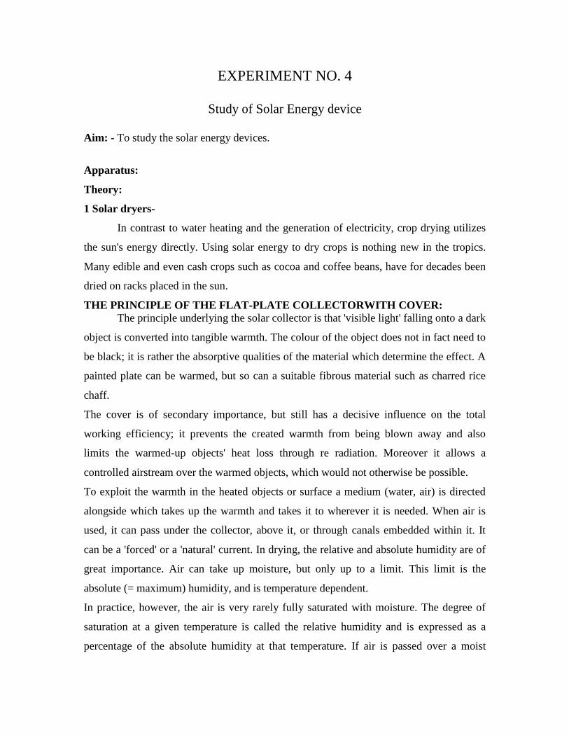
THE PRINCIPLE OF THE FLAT-PLATE COLLECTORWITH COVER:
The principle underlying the solar collector is that 'visible light' falling onto a dark
object is converted into tangible warmth. The colour of the object does not in fact need to
be black; it is rather the absorptive qualities of the material which determine the effect. A
painted plate can be warmed, but so can a suitable fibrous material such as charred rice
chaff.
The cover is of secondary importance, but still has a decisive influence on the total
working efficiency; it prevents the created warmth from being blown away and also
limits the warmed-up objects' heat loss through re radiation. Moreover it allows a
controlled airstream over the warmed objects, which would not otherwise be possible.
To exploit the warmth in the heated objects or surface a medium (water, air) is directed
alongside which takes up the warmth and takes it to wherever it is needed. When air is
used, it can pass under the collector, above it, or through canals embedded within it. It
can be a 'forced' or a 'natural' current. In drying, the relative and absolute humidity are of
great importance. Air can take up moisture, but only up to a limit. This limit is the
absolute (= maximum) humidity, and is temperature dependent.
In practice, however, the air is very rarely fully saturated with moisture. The degree of
saturation at a given temperature is called the relative humidity and is expressed as a
percentage of the absolute humidity at that temperature. If air is passed over a moist
substance it will take up moisture until it is virtually fully saturated, that is to say until
absolute humidity has been reached.
However, the capacity of the air for taking up this moisture is dependent on its
temperature. The higher the temperature, the higher the absolute humidity, and the larger
the uptake of moisture. If air is warmed the amount of moisture in it remains the same,
but the relative humidity falls; and the air is therefore enabled to take up more moisture
from its surroundings.
If fully-saturated air is warmed and then passed over the objects to be dried, the rise in
absolute humidity (and the fall in relative humidity) allows still more water to be taken
up.
Figure 1: Simple solar dryer
DIFFERENT DESIGNS AND CONSTRUCTIONS OF SOLAR DRIERS
Solar driers can be constructed out of ordinary, locally available materials,
making them well suited for domestic manufacture.
Solar driers can be divided into two categories:
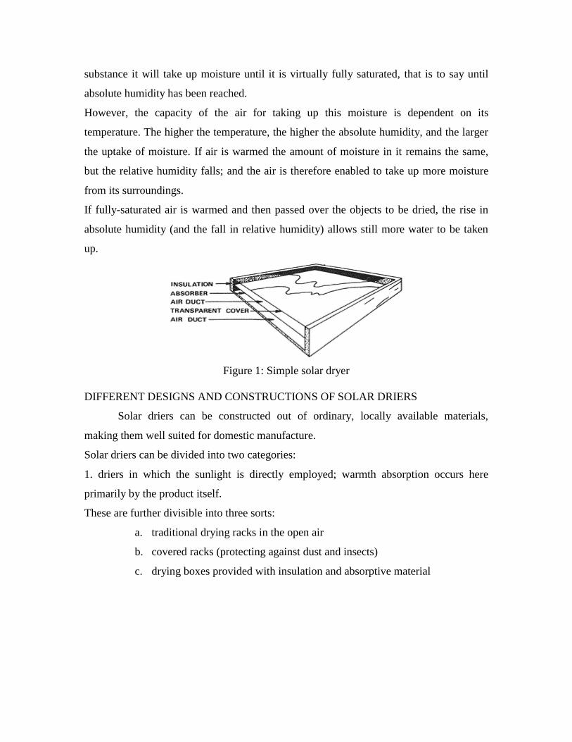
1. driers in which the sunlight is directly employed; warmth absorption occurs here
primarily by the product itself.
These are further divisible into three sorts:
a. traditional drying racks in the open air
b. covered racks (protecting against dust and insects)
c. drying boxes provided with insulation and absorptive material
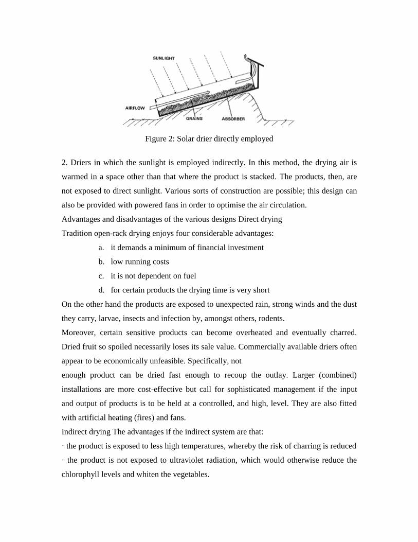
Figure 2: Solar drier directly employed
2. Driers in which the sunlight is employed indirectly. In this method, the drying air is
warmed in a space other than that where the product is stacked. The products, then, are
not exposed to direct sunlight. Various sorts of construction are possible; this design can
also be provided with powered fans in order to optimise the air circulation.
Advantages and disadvantages of the various designs Direct drying
Tradition open-rack drying enjoys four considerable advantages:
a. it demands a minimum of financial investment
b. low running costs
c. it is not dependent on fuel
d. for certain products the drying time is very short
On the other hand the products are exposed to unexpected rain, strong winds and the dust
they carry, larvae, insects and infection by, amongst others, rodents.
Moreover, certain sensitive products can become overheated and eventually charred.
Dried fruit so spoiled necessarily loses its sale value. Commercially available driers often
appear to be economically unfeasible. Specifically, not
enough product can be dried fast enough to recoup the outlay. Larger (combined)
installations are more cost-effective but call for sophisticated management if the input
and output of products is to be held at a controlled, and high, level. They are also fitted
with artificial heating (fires) and fans.
Indirect drying The advantages if the indirect system are that:
· the product is exposed to less high temperatures, whereby the risk of charring is reduced
· the product is not exposed to ultraviolet radiation, which would otherwise reduce the
chlorophyll levels and whiten the vegetables.

However, its use demands some care. Faulty stacking of the product to be dried can lead
to condensation; rising hot air in the lowest layers becomes saturated, but cools so
quickly as it rises that the water condenses out again in the upper layers.
This problem can be overcome by
· stacking the product less high
· stacking it less close together
· a larger collector, higher working temperature, faster circulation of more air, or
· a deeper collector, the same working temperature and speed of circulation but more
volume.
The higher cost and the complexity of the indirect method drier are also disadvantages.
Figure 3: Solar drier indirectly employed
2 Warming water with solar energy-
Water distillation
The simplest application of a thermal solar energy installation is in the distillation of
water. The solar distiller purifies water by first evaporating and then condensing it.
Distilled water contains no salts, minerals or organic impurities. Distilled water can be
used for: drinking water, applications in hospitals, battery water, and so on. Such an
installation is suited to areas where water is ample but polluted, salty or brackish;
naturally, there must also be abundant sun. Finally, glass or UV-resistant transparent foil
– the most important materials in the construction - must be available and affordable. A
reasonably functional solar distiller is able to produce an average of four litres of distilled
water per day per square meter of working surface.
Figure 4: Solar still: simplified cross-sectional diagram
The radiation (A) falls through the glass or plastic screen (D) onto the absorber. In
this case the absorber is a tray or basin filled with dirty water (B). Just as in the flat plate
collector's absorber, this absorber works best if the basin is black. This is especially
important if the water is clear; turbid water absorbs well enough on its own. The absorbed
radiation, then, warms the basin and, gradually, the water. To reduce heat loss to a
minimum it is vital to insulate the sides and bottom of the basin; if the basin rests on a
dry surface this actually forms a reasonable insulation. The water warms and then
evaporates, leaving the impurities behind. This vapour (C) condenses
on the underside of the screen (D) when this has a temperature appreciably lower than
that of the water and the water vapour. This will certainly be the case if wind is cooling
the screen, or the outside temperature falls as night falls. The condensate runs along the
sloping screen and into a collecting gutter. To prevent the condensate from falling back
into the water, the screen must be filled by at least 10 degrees from the horizontal. The
whole distiller must be made as airtight as possible, to prevent loss of vapour. To achieve
the best results the dirty water must be daily replaced by more water. Setting the whole
distiller at a slight angle makes this straightforward.
It will be clear from this description that this distiller lends itself well to independent
construction.
3 Solar boiler
Slightly more complex than the distiller is the solar boiler. This consists of one or more
flat plate collectors and a insulated storage tank, and is designed for use as a water heater
for hospitals, laundries, kitchens, showers, and so on.
A solar boiler with a collector surface of 3 to 4 m² and a storage capacity of 200 litres can
provide 300 to 400 litres per day of water between 40þC and 60þC in temperature.
The yield is naturally dependent on the amount of sun and on a judicious use of the
installation. The conditions for the useful application of such a solar boiler are: one, a
spot in direct sunlight as close as possible to the point of water use, and two, the
straightforward supply of (unheated) water. If a water mains system is available, this of
course offers the best solution.
Finally, the collector surface area and tank volume demand for warm water. The yield
already mentioned, 300 - 400 litres per day at 40 – 60oC for a ollector of 4 m and a 2001
tank, can be used as a guideline. If more water is
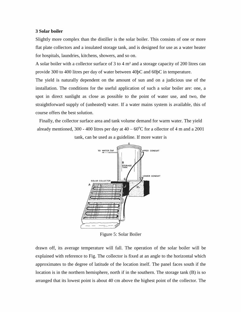
Figure 5: Solar Boiler
drawn off, its average temperature will fall. The operation of the solar boiler will be
explained with reference to Fig. The collector is fixed at an angle to the horizontal which
approximates to the degree of latitude of the location itself. The panel faces south if the
location is in the northern hemisphere, north if in the southern. The storage tank (B) is so
arranged that its lowest point is about 40 cm above the highest point of the collector. The
warm water outlet (C) connects the higher outlet of the connector to the top of the warm
water tank; a cold water supply pipe runs from the bottom of the storage tank to the lower
part of the collector. The cold mains water supply also runs into the bottom of the tank,
and the warm water draw-off pipe is fixed to the top of the tank. If the tank is now filled
with cold water it will pass via (D) into the (lower) collector. If the sun shines the water
will warm up and will pass via (C) to the top of the tank. This happens on its own,
because warm water moves upwards The sun therefore generates a circulation of water
between the collector and the tank, called 'natural circulation' or 'thermosyphon'. No
pump is needed. The water in the tank gradually warms up until it is drawn off and cold
water comes in to replace it. If the storage tank is well insulated, the water remains warm
into the evening and even the early morning. The nice thing about this self-starting
system is that it is practically maintainance-free.
4 Cooking with solar energy
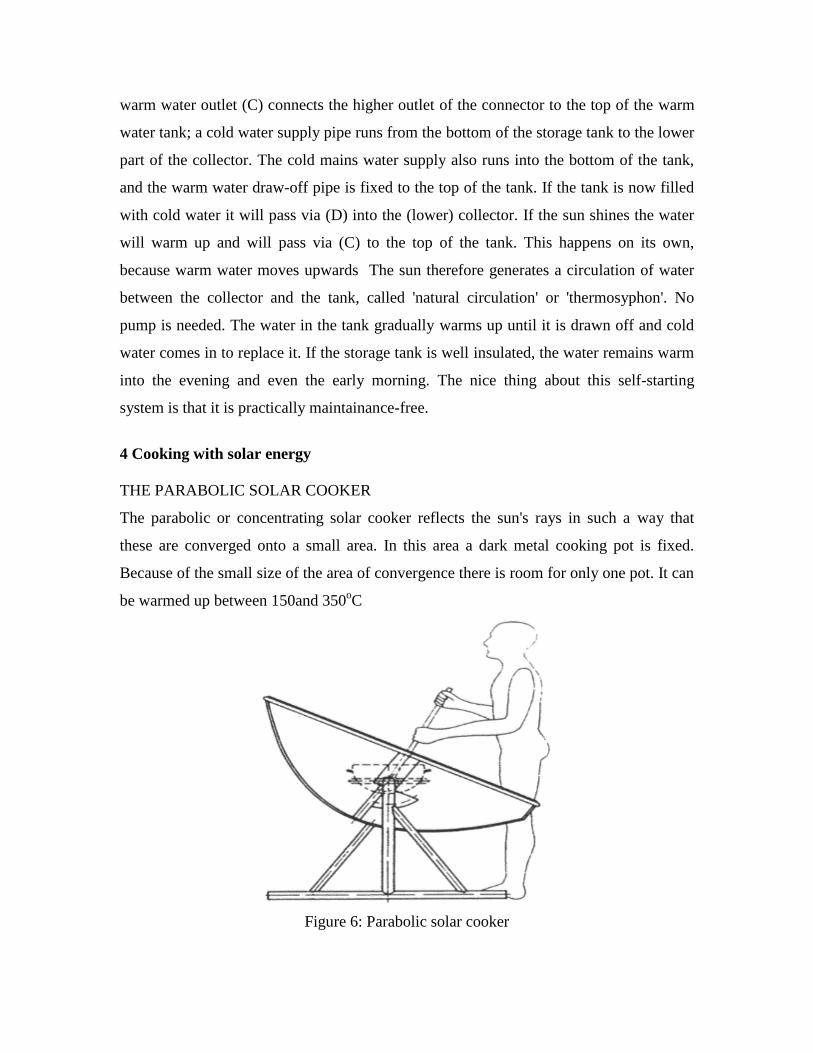
THE PARABOLIC SOLAR COOKER
The parabolic or concentrating solar cooker reflects the sun's rays in such a way that
these are converged onto a small area. In this area a dark metal cooking pot is fixed.
Because of the small size of the area of convergence there is room for only one pot. It can
be warmed up between 150and 350oC
Figure 6: Parabolic solar cooker
However, the design does suffer some serious disadvantages. The reflector has to be
realigned as often as every ten minutes, because the sun's movement shifts the
convergence point accordingly. This means continual attention during cooking. Another
disadvantage is the higher temperature - carelessness can result in burns - and the
disagreeable reflections of light.
Besides the problems of its use, the construction of such a parabolic reflector poses
difficulties. The reflecting surface's curve must be extremely precise; this exactness is not
always achieved. The apparatus is, moreover, often sensitive to wind.
THE COOKING BOX
The cooking box works on the principle of the retention of warmth. The box must be well
insulated, so as to retain the energy that shines into it; for this reason the box cannot be
opened during cooking. If this should happen, the loss of heat will considerably slow
down the preparation of the meal. This limitation also means that meals that need to be
prepared step by step are unsuited; so an effective menu plan, prepared beforehand, is
viral. A cooking box is easy enough to make on one's own; the following introduction
looks at what comes into such construction.
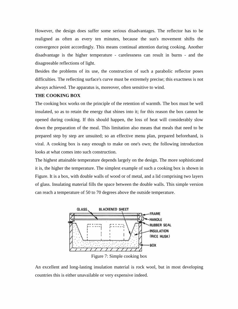
The highest attainable temperature depends largely on the design. The more sophisticated
it is, the higher the temperature. The simplest example of such a cooking box is shown in
Figure. It is a box, with double walls of wood or of metal, and a lid comprising two layers
of glass. Insulating material fills the space between the double walls. This simple version
can reach a temperature of 50 to 70 degrees above the outside temperature.
Figure 7: Simple cooking box
An excellent and long-lasting insulation material is rock wool, but in most developing
countries this is either unavailable or very expensive indeed.
Other insulating materials include cotton, wood shavings, coconut fibre and straw. These
materials do not need to be packed densely in, or scattered loosely; firm pressure is
enough. The material must be very dry and it must remain so; for this reason a metal
inner box is preferable to a wooden one which is comparatively difficult to make
watertight. It is advisable to paint the bottom of the inner surface of the cooker matt
black. The sides can be painted reflective (shining). As this is to obtain the best possible
absorption of the sun's rays, a matt paint is most important, and a matt dark blue works
better than a shiny black. It is advisable to have outward-tapering walls rather than
upright ones, as these prevent shadowing the interior; and high temperatures are more
likely if the whole box is shallow. The food to be cooked is placed, in a matt black pan, in
the box. The pan may be made of thin metal; this often gives the best results, but such
pans are not too strong. The pan should be covered with a lid, to prevent condensation
forming on the glass and to speed the cooking. The cooking time in such a cooking box is
considerably longer than normal. The temperatures reached by the design shown in
Figure would be too low for many cooking purposes. Filling the box with one or more
reflectors can appreciably raise the maximum temperature. An example of a cooking box
filled with a reflector. The reflector increases the amount of incident light, whereby
higher temperatures are attained more quickly.
RESULT: Hence we studied different solar energy devices.
EXPERIMENT NO. 5
Assignment on Topic: Entropy
Q.1 What do you mean by the term ‘Entropy’?
Q.2 Prove that entropy is a property of a system.
Q.3 What is a temperature-entropy diagram?
Q.4 Give an expression for entropy changes for an open system.
Q.5 Two unsolved problems.
EXPERIMENT NO. 6
Assignment on Topic: Air Standard Cycle
Q.1 Explain “Air standard analysis” which has been adopted for I.C. engine
cycles. State the assumptions made for air standard cycles.
Q.2 Derive expressions of efficiency in the following cases:
(i) Carnot cycle
(ii) Diesel cycle
(iii) Dual combustion cycle.
Q.3 What is a cycle? What is the difference between an ideal and actual
Cycle ?
Q.4 Two unsolved problems.


![ESL Lab Manual1[1]](https://img.pdfslide.us/doc/110x75/577d33ef1a28ab3a6b8c24dd/esl-lab-manual11.jpg)