Embed Size (px)
Citation preview

- 2 - SCS Static Control Systems S.r.l. - ITALY -
www.scs.it - Verderio Inf. (LC) 23879 - via Piave n.84 Tel. +39-039.99956.1 Fax. +39-039.99956.30
The Company SCS Static Control Systems has been successfully operating in the industrial automation field since 1977. In the beginning, the company designed and manufactured static electrical controls for automated machines and systems and, starting in 1978, it began designing and manufacturing analog converters for DC-powered motors. Thanks to its technical expertise, in 1986 SCS was chosen by Mitsubishi Electric as the sole distributor for Italy. In 1994, the company began manufacturing analog drives for trapezoidal brushless motors and in 1997, it designed and manufactured the first family of digital drives for sinusoidal brushless motors. In just a few years, the sinusoidal vector converter became the company’s leading product and in 2005, a new generation of brushless motor drives was launched to upgrade the control section of the motor. The recent release of third-generation brushless servo drives crowns the 10 years evolution of the product line. SCS operates in Italy and abroad currently offering a wide services portfolio. From analog and digital systems design, based on the expertise of its R&D department, to system integration design and deliver, based on the experience and know-how of its Engineering Department. The corporate mission is focused on quality, flexibility and the ability to assist the customer through all phases of machine realisation. After-sales service and technical support have also always been a significant part of corporate policy and have become well-known and appreciated by all operators in the industry. The Research & Development Dept. SCS’ pride is its R&D team, which designs innovative solutions to support the most demanding performance requirements of the market. The company provides consulting and engineering services while continuously ensuring a complete product customization. Qualified engineers always up-to-date to the latest technologies concerning development platforms, design the hardware and software for our products while focusing on innovation and reliability. Digital solutions have been studied to facilitate the task of machine design engineers and the most advanced tools have been used to simulate, debug and test new-generation DSP and FPGA platforms. The daily exchange of information between the Technical Support and R&D department leads to continuous product evolution, which not only allows the customer to make the most suitable technical choices, but also guides our company to identify specifications for new product generations. The Engineering Dept. The significant experience gained by designing systems based on all state-of-the-art products on the market, has allowed SCS’ Engineering Department to ensure maximum reliability and expertise. Specifically, SCS is a SIEMENS Certified System Integrator, thanks to 30 years of experience using specific products for the industrial automation industry. Our Engineering Department’s hardware and software design engineers look for increasingly innovative solutions to simplify the commissioning and the maintenance of the systems and to achieve increasingly high performance. Our technicians’ significant design experience allows them to manage commissioning and start-up phases in a timely and safe manner. The production Every internal phase including production, assembly and testing is performed by qualified personnel under the supervision of highly experienced managers. Thanks to close collaboration and co-design with our suppliers, the quality of our components is also constantly under control, thus guaranteeing maximum product reliability. In fact, SCS products undergo rigorous static and functional testing procedures, both for the Systems Division as well as for the Drives Division. Our personnel is continuously trained and this contributes to spread inside the company the mission concepts such as quality assurance, proactive testing and specific expertise regarding all production process phases. The R&D department provides technicians and testing operators, support regarding all requests for personalisation or to successfully pass the commissioning phase. These are just a few reasons why SCS is truly an ideal partner when it comes to positive, long-lasting collaboration based on significant technological value. SCS has made its name in the sector over the years thanks to the excellent quality of its staff. Our staff has played an important role in this growth through constant updates and professional improvements in order to respond to increasingly strict quality standards, thereby making a vital contribution to the success of the company.
- 3 - SCS Static Control Systems S.r.l. - ITALY -
www.scs.it - Verderio Inf. (LC) 23879 - via Piave n.84 Tel. +39-039.99956.1 Fax. +39-039.99956.30
INTRO
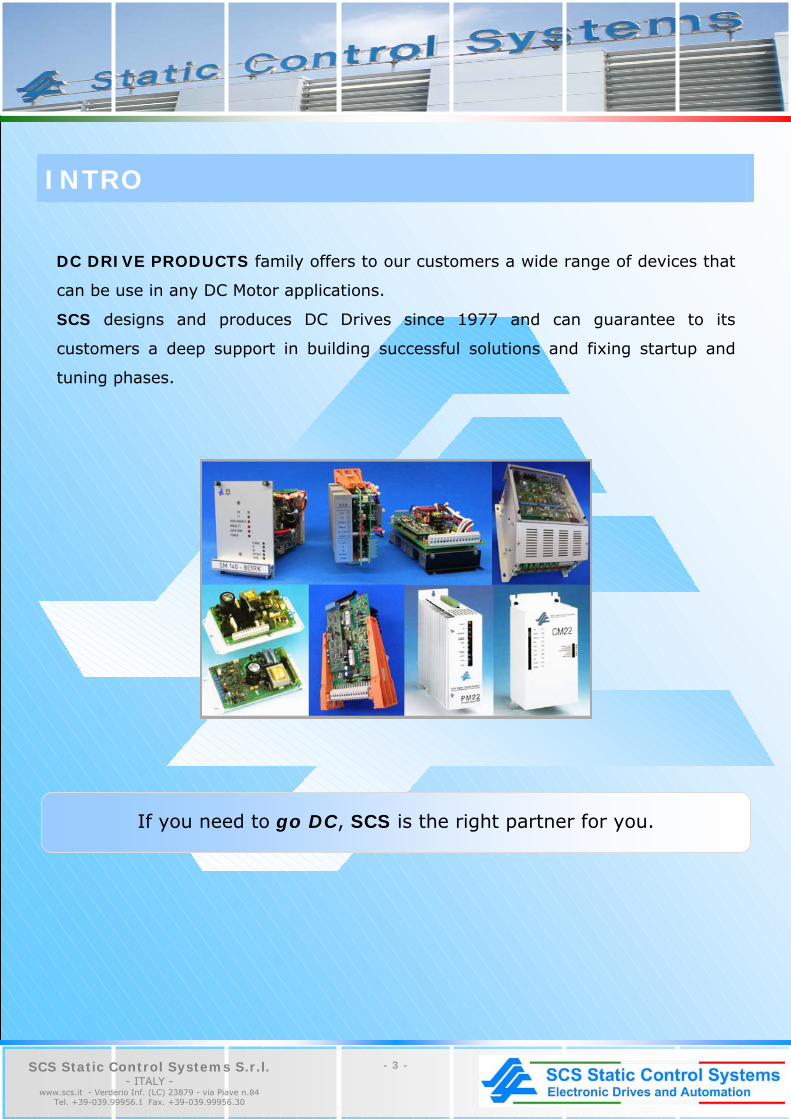
DC DRIVE PRODUCTS family offers to our customers a wide range of devices that
can be use in any DC Motor applications.
SCS designs and produces DC Drives since 1977 and can guarantee to its
customers a deep support in building successful solutions and fixing startup and
tuning phases.
If you need to go DC, SCS is the right partner for you.

- 4 - SCS Static Control Systems S.r.l. - ITALY -
www.scs.it - Verderio Inf. (LC) 23879 - via Piave n.84 Tel. +39-039.99956.1 Fax. +39-039.99956.30
SUMMARY
FULL CONTROLLED
CT38 2/4 QUADRANT FULL CONTROLLED THREE-PHASE DRIVES FOR D.C. MOTORS – SERIES CT 6
CM38 4 QUADRANT FULL CONTROLLED SINGLE PHASE DRIVES FOR D.C. MOTORS – SERIES CM 9
CM220-TR 4 QUADRANT FULL CONTROLLED SINGLE PHASE DRIVES FOR D.C. MOTORS – SERIES CM 11 HALF CONTROLLED
CM22 HALF-CONTROLLED SINGLE PHASE CONVERTER 14
CM 220-9S UNIDIRECTIONAL SINGLE-PHASE HALF-CONTROLLER CONVERTER OPERATIONS ON 1 QUADRANT 16 DC SERVO DRIVES
CH220 - CH22 UNIDIRECTIONAL MOSFET DRIVE 19
ST EUROCARD E1 ST SERIES TRANSISTOR PWM SERVO AMPLIFIER FOR D.C. MOTORS 21
SM EUROCARD E1 SERIES MOSFET PWM SERVO AMPLIFIERS FOR D.C. MOTORS 24 PHASE SHIFTERS
PM22 FULL-WAVE PHASE CONTROL CHARACTERISTICS 28
PS380 FULL-WAVE PHASE CONTROL CHARACTERISTICS 30

- 5 - SCS Static Control Systems S.r.l. - ITALY -
www.scs.it - Verderio Inf. (LC) 23879 - via Piave n.84 Tel. +39-039.99956.1 Fax. +39-039.99956.30
CT38 2/4 QUADRANT FULL CONTROLLED THREE-PHASE DRIVES
CM38 4 QUADRANT FULL CONTROLLED SINGLE PHASE DRIVES
CM220-TR 4 QUADRANT FULL CONTROLLED SINGLE PHASE DRIVES

- 6 - SCS Static Control Systems S.r.l. - ITALY -
www.scs.it - Verderio Inf. (LC) 23879 - via Piave n.84 Tel. +39-039.99956.1 Fax. +39-039.99956.30
CT38 2/4 QUADRANT FULL CONTROLLED THREE-PHASE DRIVES FOR D.C. MOTORS – SERIES CT APPLICATIONS Unidirectional and bidirectional drives for medium and large power d.c. motors. Constant power and constant torque speed adjustment for spindles, CNC’s and machine tools. Processing lines for plastic and rubber materials, extruders, pinch roll trains, winding machines, mixers, calenders. Metal wire and sheet working machines, shears, reels, cutters, wire drawing benches, spooling machines, stranding machines, rolling mills, forging machines, flattening machines. Paper product making and packaging machines, paper mills, packaging industries. Printing machines, including silk-screen printing, offset, rotogravure and continuous machines. Voltage and/or current regulators for controlling processes, RL loads, galvanic baths, electrophoresis. MAIN FEATURES Full standardization design philosophy. Removable personalization board. Standard control boards without calibration. Optimum power, size, performance and cost ratio. Direct connection to mains with wide tolerance (± 20%) and random phase sequence. Very wide current range from 30A to 2700A; built-in voltage changes for mains 220, 380,440, 480 V ± 20%. Galvanic isolation, also in armature feedback, with compensation Rxl. Adjustable speed relay (0.5 to 120%). Thermal overload prealarm relay (l2t). Electronic thermal images. Provision for setting (1.5x In per 30 s.) and disabling overload. Commands for controlling references and functions, with LED signalling handled by the PLC or process controls. Analog current and speed outputs. Differential proportional amplifier, configurable by the
user. Transmission outside of the status of the protective devices, optically isolated parallel and serial. Standard built-in protective devices (controls of mains and internal power supplies, pulse suppression, solid-state and/or electromechanical fuse alarm, overvoltages, tacho generator failure, field circuit checking, overtemperature, external alarm available) all with LED signalling.
1.1. GENERAL DESCRIPTION The compact modular construction uses standard PC boards for the entire range, with high level of integration of the components mounted. Thanks to this it is possible to have a series with practically all the most frequently used system auxiliary functions. Through external commands (contacts or PLC commands signalled by LED’s), it is possible to have full control over the switching of the reference signals, Forward/Reverse commands, selection of inputs and use of the ramp. The Forward/Reverse of the reference signals and JOG presettings are interlocked. All protective devices are memorized individually.Moreover they are signalled by LED's, with external communication in optically isolated parallel form, or transmission in serial form. The PC board is standard without adjustment. The personalization and calibration board contains all the adjustments and presettings with an amplifier which can be configured as required. A special thermal image calculation circuit allows both overloading (3 to 30 s.) as well as boosted continuous service, which is useful for current regulators in “pull mode” with unit torque (torque controls). In order to afford full protection to the drive, all fuses necessary for the power section are installed internally (SCR bridge, ventilation, field circuit, power supply). The drive is built to IEC standards 146,146A,146.2,VDE110b, IEC 494-CT 22-2 and the ANIE recommendations. Components with UL, CSA and VDE mark are used. There is provision for mounting fuses to BS88 part 4-1976 and IEC 269 part 4 (standard) and type XL-F and SF to UL standards (upon request). The drive is rated for mains power supplies up to 500V±10%.
1.2. INTERNAL PROTECTIVE DEVICES Main fuses (3) for the power bridge (version CT..T/VT) with fuses on the dc side (external) only when used as an inverter rectifier (unidirectional, 2 quadrants) Branch fuses (6) for version CT..TR/VTR (reversible, 4 quadrants) Fuses for the field bridge (2) Fuses for the fan (2) when provided (only for CT…V) Fuses for the control circuit (3) Checking of firing of each single SCR, solid-state fuse alarm, with provision for optional internal and/or external additional electromechanical checking (AF), provision for disabling. Pulse suppression for uncontrollable d.c. overcurrent (200%) (SI). Check for mains tolerance missing phases, mains failures presence of – 15V (CR). Check for overvoltages and efficiency of peak voltage killer filter (only for high power ratings) (FS) Checking for tacho generator failure (ADT). Checking of field circuit by means of adjustable transducer (MCE) Thermal overload protection through thermal element on the radiator and calculation of thermal image limiting (TH) Signalling of prealarms through relays at 80% of time limit (l2t). Auxiliary protection available (external trip); provision for use as signalling or memorized stop (ET) N.B.: all protective devices are sent at output through connector X3, individually through OPTO and in serial form for connection to receiver RX8.
- 7 - SCS Static Control Systems S.r.l. - ITALY -
www.scs.it - Verderio Inf. (LC) 23879 - via Piave n.84 Tel. +39-039.99956.1 Fax. +39-039.99956.30
2.0. CALIBRATION AND PERSONALIZATION BOARD (i.e. T-RT2, T-RT2R) Implemented with passive and/or calibration components (apart from the auxiliary amplifier). The board is with plug-in connector and can be replaced by a more sophisticated uP board. settings through trimmers Nmax, Nmin, JOG, + a, - a, + Imax, - Imax, AZZ, Rxl, D-VEL, P-VEL, I-VEL, G2, P-COR, I-COR, In, TI2t, IE, VO. Available presettings AR/DT, JCR/JSR,CR/SR, - E1/E1 8 – position dip switches for programming and/or disabling certain protective devices or commands.
3.0. ADJUSTMENT BOARD RT2-RTR2 Fully standard, without any calibration Provision for back panel mounting of an optional board in E1 format (100x160). 4.0. POWER SECTION Full controlled three phase SCR bridge (6SRC’s) for the CT..T/VT version and with 6+6 SCR’s in anti-parallel (CT..TR/VTR) complete with fuses, filters, single RC filters and protection against overvoltage and dv/dt. SCR firing board (ZT6/ZT12) adiacent to the modules. Board with filters, auxiliary fuses and isolating transducers for armature and field.
5.0. SPECIFICATION Standard supply voltage for control circuit, 3 x 220, 380, 440, 480 ± 20% with built-in voltage change (200 ± 10%, 235±10%, 415±10%, 420±15%, 460±15%, 500V±10%). Set of 3 fases with random sequence. Standard power circuit supply voltage (3x 415V) ± 10% max. Max voltage 3x500V± 10% (upon request, for CT44..CT48..) Frequency 50Hz ± 4% or else 60 Hz ± 4% (set by SW6) Forced ventilation: 220V single phase 50/60 Hz only for types CT..VT/VTR Operating temperature range: 0°C to 45°C (effective) (inside the control panel) for unventilated models, at nominal current (35°C for ventilated models) Max permissible operating temperature : 65°C with down grading of 1.25% for each degree from 45° (35°) up to 65°C. Storage temperature range : - 25°C to + 85°C. Relative humidity 50% without condensate Altitude 1000 m above sea level, with down grading of 1.2% for every 100m above this altitude. Max form factor 1.05 Field circuit supply voltage 2x415V ± 10%max; complete with fuses, transducer, protective devices. Single phase full bridge. Max current 12A (20A upon request) Adjustment characteristic : double closed loop in series, for current (TA) and speed (DT) or voltage (VA) Adaptive characteristic adjustable with trimmers (P-COR, I_COR) for current loop, D-VEL, P-VEL, I-VEL for speed loop). Typical range of adjustment 1/200 with tacho gen. Feedback 1/20 with armature feedback and RX1 compensation. Static speed error with tacho feedback with transient finished and excluding the speed transducers errors :
± 0.01% of max speed for load variation from 5% to 100%; ± 0.05% of actual speed for mains fluctuations of 20%; ± 0.01% of actual speed for each degree in ambient
temperature change from 0° to 65°C.
Internal reference voltage ± 10V ± 2% typical, 20mA max Reference potentiometer : standard value 5K (from 1K to 10K) Input impedance of reference signal : 44K ± 2% (0.23 mA typical) Positive logic commands (standard + 24V ± 20% 5mA), immunity level 13V at 1.5mA. Contacts or PNP outputs from PLC Thermal image l2t, adjustable (3s±30s) with duty cycle 1/20; can be disabled. Standard overloading 1.5x In for 30 sec. Optically isolated outputs for the protective devices, loading capacity 30mA/35V max Serial output for connection with alarms receiver Rx8 Relay output 5A/220V load R, 3A/220V load RL Available outputs + 15V/20mA, -15V/20mA, + 24V/100mA Analog outputs for speed and current signals, with actual sign; ± 10Vmax ± 1mA max Auxiliary circuits mounted as standard: Speed ramp: 2 to 60 sec. (0.2 to 6 sec. In RAP), independent +a, -a, reset (RV) Speed relay: adjustable from 0.5% to 120% (NR) Check for field failure: adjustable from 0.25% to 100% (MCE) Thermal image l2t; total time adjustable from 3 to 30 s. Current from 50 to 100% Prealarm relay Mains check (CR) – Pulse suppression (SI) – Tacho generator alarm (ADT) – Check for switching on and solid-state fuse alarm (CA+AF) – Armature transducer (TV) – Proportional amplifier (1/2 AP2)

- 8 - SCS Static Control Systems S.r.l. - ITALY -
www.scs.it - Verderio Inf. (LC) 23879 - via Piave n.84 Tel. +39-039.99956.1 Fax. +39-039.99956.30
6.0. APPLICATION TABLE
ARMATURE VOLTAGE (3)
MOTOR POWER KW (4)
DIMENSIONS
DRIVE
In
Ip
Ith
CT..T
CT..TR
CT..T
CT..TR
W
H
D
MAIN IND.
WEIGHT kg CT..TR
CT38 30…
CT38 46…
CT38 55…
CT38 75…
CT38 83…(x)
CT38 105V…
CT38 135V…
CT38 155V…
CT38 240V…
CT38 300V…
CT38 330V…
CT38 390V…
CT38 425V…
CT38 510V…
CT38 600V…
CT38 735V…
CT38 1000V…
CT38 1270V…
CT38 1400V…
30
46
55
75
83
105
135
155
240
300
330
390
425
510
600
735
1000
1270
1400
45
70
85
110
125
155
200
230
360
450
495
585
635
765
900
1100
1500
1900
2100
37
55
70
90
103
135
180
200
325
405
445
530
575
620
750
900
1200
1550
1750
440
440
440
440
440
440
440
440
440
440
440
440
440
440
440
440
440
440
440
400
400
400
400
400
400
400
400
400
400
400
400
400
400
400
400
400
400
400
11 (14)
(20)
(26)
(33)
(38)
(50)
50 (70)
62 (79)
94 (128)
118 (160)
130 (176)
155 (209)
168 (227)
202 (273)
237 (297)
291 (356)
396 (475)
503 (614)
555 (693)
(12)
(19)
(24)
(31)
(36)
(47)
47 (64)
55 (72)
85 (117)
108 (145)
118 (160)
140 (190)
153 (207)
183 (248)
216 (270)
264 (324)
360 (432)
457 (558)
505 (630)
280
280
280
280
280
280
280
280
350
350
450
450
450
450
xx
xx
xx
xx
xx
385
385
385
385
385
505
505
505
605
605
630
630
630
630
xx
xx
xx
xx
xx
230
230
230
230
230
230
230
230
275
275
290
290
290
290
xx
xx
xx
xx
xx
LT40
LT41
LT42
LT43
LT44
LT45
LT46
LT47
LT48
LT49
LT50
LT51
LT52
LT53
LT54
LT55
LT56
LT57
LT58
10
10
10
11,5
11,5
13
13
13
23,5
23,5
33
33
33
33
NOTE: Other sizes upon request, up to 2700A 1 – Max permissible overcurrent for 30 sec. (60 sec. For CT38 – 600 ÷ 1400) – duty cycle 1/20 2 – Thermal current permissible without overload (IEC 146 – class I) 3 – Armature voltage for power supply 3x380 ± 10% IEC 146 4 – Typical motor power ratings which can be used, with efficency between 0,85 and 0,9, overload of 50%, and mains 380V. In brakets are stated the typical powers without overload, calculated with Ith. For mains different from 380V, calculate the proportion. (x) – Only upon request xx – To be built in the cabinet; see NT099 – 5.16 for dimensions
Ordering code:
CT 38 155 (V) T (R)
Digital converter
Mains voltage: 38 for mains from 200 to 415V
44 for mains from 200 to 460V 48 for mains from 200 to 500V Continuous current (from 30A to 1400A)
Forced ventilation
Full controlled (2Q)
Reversible (4Q)

- 9 - SCS Static Control Systems S.r.l. - ITALY -
www.scs.it - Verderio Inf. (LC) 23879 - via Piave n.84 Tel. +39-039.99956.1 Fax. +39-039.99956.30
CM38 4 QUADRANT FULL CONTROLLED SINGLE PHASE DRIVES FOR D.C. MOTORS – SERIES CM APPLICATIONS Bidirectional drives for small and medium power D.C. motors Processing lines for plastic and rubber materials extruders, pinch roll trains, winding machines. Metal wire and sheet working machines, shears, cutters, spooling machines, strading machines. Paper product making and packing machines, packaging industries. Printing machines, including silk screen, offset. Positioning gauges, transfer.
MAIN FEATURES Full standardization design philosophy Standard control board with SMT technology Optimum power, size, performance and cost ratio Direct connection to single phase mains with wide tolerance (±20%) Selection of the full range current iî binary code (4 bit) Selection on terminal board for main 220, 380, or 240, 440,480 ±20% Galvanic insulation, also in armature feedback, with compensation Rxl Double slope speed ramps, selectable and with separate zeroing Adjustable speed relay(0,5 ÷ 120%) OK relay cumulative of all the protective devices ‘DRIVER OK’ Thermal overload prealarm relay (l2t). Electronic thermal images Provision for setting (1,5 x In per 30 s.) and disabling overload Commands for controlling reference and functions, with LED signalling Analog current and speed outputs Standard built-it protective devices (controls of mains and internal power supplies, solid state and/or electromechanical fuse alarm, tacho generator failure, field circuit checking disabling by external command, overtemperature) all with LED signalling.
1.0 GENERAL DESCRIPTION The compact modular construction uses standard PC boards for the entire range. The high level of integration of the components mounted, made possible to have a series with practically all the most frequently used system auxiliary functions. Through external commands(contacts or PLC commands signalled by LED's), it is possible to have full control over the switching of the reference signals, Forward/Reverse commands and use of the ramp. All protective devices are memorized individually and signalled by LED's. The PC board is standard. A special thermal calculation circuit allows both overloading (30s) and boosted continuous service, which is useful for current regulator in 'pull mode’ with unit torque (torque controls). The drive is built accordinç to IEC standards 146, IEC 326, VDE 110b, CEI 494-CT22-2 and the ANIE recommendations. The drive is rated for mains power supplies up to 500V ± 10%. All auxiliary fuses (field, regulation) are internally mounted. Power fuses are externally mounted. 2.0 INTERNAL PROTECTIVE DEVICES Fuses for the field bridge (2) Fuses for the control circuit (1) Checking of firing of each single SCR, solid-state fuse alarm, with provision for optional external additional electromechanical checking (AF) and provision for disabling. Check for mains tolerance, missing phases, mains failure, presence of -15V Checking for tacho generator failure Checking of field circuit by means of adjustable transducer; provisions for disabling by command
Thermal overload protection through thermal element on the radiator and calculation of thermal image limit Signalling of prealarms through relays at 80% of time limit of thermal images
2.1 STATUS LED ON BARGRAPH PW: power alarm (mains, fuses) TG: tacho generator alarm FC: field circuit checking TH: thermal alarm(thermostat/I2t) MP: positive modulator (forward bridge) MN: negative modulator (reverse bridge) I>In: start of thermal image calculation I2t: thermal prealarm N≠0: speed relay OKD: driver OK (alarm cumulative)
3.0 CONTROL BOARD RR2 CARD Fully standard for all ranges Available presetting AR/DT, JCR/JSR, RV1/RV2 4-positions dip switches for programming and/or disabling certain protective devices or commands
4.0 POWER SECTION PR2 CARD Full controlled single phase 4+4 SCR's in anti-parallel, complete with single RC filters and protection against overvoltage and dv/dt Boards with filters, auxiliary fuses and insulating transducers for armature and field

- 10 - SCS Static Control Systems S.r.l. - ITALY -
www.scs.it - Verderio Inf. (LC) 23879 - via Piave n.84 Tel. +39-039.99956.1 Fax. +39-039.99956.30
5.0 TECHNICAL DATA Standard supply voltage for control circuit 220, 380, or 240/440, or 240/480 ±20% with selection on terminal board (200 ± 10%, 235 ± 10%, 240 ± 20%, 415 ± 10%, 420 ± 15%, 460 ± 15%, 500V ± 10%). Standard power circuit supply voltage 415V ± 10% max Max voltage 500V ± 10% (upon request, for CM44...CM48) Frequency 50Hz ± 4% or 60Hz ± 4% (set by SW 1-4) Ref. ambient temperature: 0° to 45°C effective (inside the control panel) Max operating temperature: 65°C with derating of 1,25% for each degree from 45° up to 65°C Storage temperature range: da –25° a +85°C Relative humidity ≤50% without condensation Altitude ≤1000 m.a.s.l. with derating of 1,2% for every 100m above this altitude Max form factor 1,2 Field circuit supply voltage 2 x 415V ± 10% max, with single phase bridge, complete with fuses, transducer, protective devices. Max current 2,5A. Adjustment characteristic: double closed loop in series, for current (TA) and speed (DT) or voltage Typical range of adjustment 1/100 with tacho gen. feedback or 1/10 with armature feedback and RXI compensation. Static speed error with tacho feedback and transient finished and excluding the speed transducer errors
± 0,01% of max speed for load variation from 5% to 100% ± 0,05% of actual speed for mains fluctuations of ± 20% ± 0,01% of actual speed for each degree in ambient temperature change from 0° to 65°C Internal reference voltage ± 10V ± 2% 10mA max Reference potentiomenter: standard value 5K (da 1K a 10K) Input impendance of reference signal: 200K ± 2% (0,05mA typical) Positive logic commands (standard ± 24V ± 20% 5mA) immunity level ≥13V at 1,5mA. Contacts or PNP outputs from PLC Thermal image I2t with duty cycle 1/20; can be disabled. Standard overloading 1,5xIn for 30sec. Relay outputs 5A/220V load R, 3A/220V load RL Available outputs: +15V/10mA, -15V/10mA, +24V/30mA Analog outputs for speed and current signals, with actual sign: ±10Vmax, ±4mA max Auxiliary circuits mounted as standard Speed ramp: 3÷90 sec., ±20% (or 0,3÷9 sec., or 3ms.÷0,1sec.) independent +a, -a, independent stop Speed relay: adjustable from 0,5% to 120% with trimmer Check of field failure: adjustable from 100mA to 2,5A. Standard value 100mA ± 20% Thermal image I2t: total time 30sec. ±20% Prealarm relay
6.0 APPLICATION TABLE
CURRENT VOLTAGE (3)
VOLTAGE (3)
DIMENSIONS
WEIGHT
DRIVE
In Ith
(1) Ip 2)
mains V~
arm.V=
MOTOR POWER KW (4)
mains V~
arm.V=
MOTOR POWER KW (4)
W
H
D
Kg
CM38-11 TR
CM38-14 TR
CM38-22 TR
CM38-33 TR
(x) CM44-11 TR
(x) CM44-14 TR
(x) CM44-22 TR
(x) CM44-33 TR
(x) CM48-11 TR
(x) CM48-14 TR
(x) CM48-22 TR
(x) CM48-33 TR
11
14
22
33
11
14
22
33
11
14
22
33
14
18
26
40
14
18
26
40
14
18
26
40
16
21
33
50
16
21
33
50
16
21
33
50
220
220
220
220
240
240
240
240
240
240
240
240
150
150
150
150
170
170
170
170
170
170
170
170
1,3
1,7
2,8
4,2
1,4
1,9
3,1
4,7
1,4
1,9
3,1
4,7
380
380
380
380
440
440
440
440
480
480
480
480
260
260
260
260
300
300
300
300
330
330
330
330
2,3
3
4,8
7,2
4,6
6
9,6
14
5
6,6
10,5
15
190
190
190
190
190
190
190
190
190
190
190
190
275
275
275
275
275
275
275
275
275
275
275
275
165
165
165
165
165
165
165
165
165
165
165
165
2,3
2,5
3,7
3,8
2,3
2,5
3,7
3,8
2,3
2,5
3,7
3,8
NOTE (1) – Thermal current permissible without overload (IEC 146 – class I) (2) – Max permissible overcurrent for 30 sec. duty cycle 1/20 (3) – Mains and motor voltage according to IEC 146 (for other power supplies, please check manual) (4) – Typical motor power ratings which can be used, with efficency between 0,8 and 0,85, overload of 50% and typical power supplies. For different mains, calculate the proportion (see manual) (x) – Only upon request Order code : CM 38 - 14 TR
Single phase converter
Mains voltage (CM38… CM44… CM48…)
Continuous current (from 11A to 33A)
Full controlled Reversible (4Q)

- 11 - SCS Static Control Systems S.r.l. - ITALY -
www.scs.it - Verderio Inf. (LC) 23879 - via Piave n.84 Tel. +39-039.99956.1 Fax. +39-039.99956.30
CM220-TR 4-QUADRANT SCR BIDIRECTIONAL FULL CONTROLLED SINGLE-PHASE CONVERTER APPLICATIONS • reversible control of low power D.C. motors • Silkscreen machinery • Footwear machinery • Copying machines • Conveyors MAIN FEATURES • Direct installation on single-phase mains supply • Excellent dimension/cost/performance ratio • Operating range: from 5A to 10 A • Independent circuit for the supply of the field circuit • Internal fuses protection GENERAL DESCRIPTION The converter CM 220/5-9-16TR is intended for the reversible supply of low power D.C. motors. The output current is of 5A, 9A, 16A, while the max. output voltage is of 150V. It allows operation in the 4 quadrants, with 8 SCR static switching. An independent circuit for the supply of the field circuit is available. The protection with fuses of the power, field and control circuits is internal. The speed ramp circuit is standard supplied, and can be separately adjusted for the 2 directions of acceleration. A zero speed relay, analog current and speed output are, current limit analog input also available; GENERAL DESCRIPTION The converter CM 220/5-9-16TR is intended for the reversible supply of low power D.C. motors. The output current is of 5A, 9A, 16A, while the max. output voltage is of 150V. It allows operation in the 4 quadrants, with 8 SCR static switching. An independent circuit for the supply of the field circuit is available. The protection with fuses of the power, field and control circuits is internal. The speed ramp circuit is standard supplied, and can be separately adjusted for the 2 directions of acceleration. A zero speed relay, analog current and speed output are, current limit analog input also available; APPLICATION TABLE
CM220 5TR 9TR 15TR Max. armature voltage V 150 150 150 Max. armature current A 5 9 16 Max. form factor 1.2 1.2 1.2 Converter power KW 0.750 1.35 2.4 Typical motor power KW (with n=0.8 and Cp=1.5Cn)
0.4 0.72 1.2
Armature inductance mH (typical for F.F. = 1.1)
175 100 50
It A 4 7.5 11 Is A 6 10 17 Field voltage V 198 198 198 Field current A 1.5 1.5 1.5 Converter weight Kg 1.2 1.2 1.8 Dimensions: width mm 138 138 140 height mm 222 222 200 depth mm 70 70 70
- 12 - SCS Static Control Systems S.r.l. - ITALY -
www.scs.it - Verderio Inf. (LC) 23879 - via Piave n.84 Tel. +39-039.99956.1 Fax. +39-039.99956.30
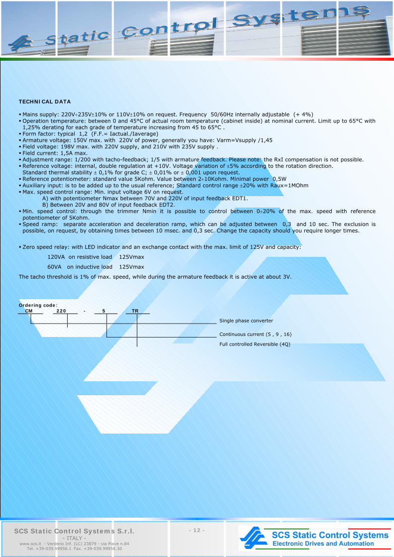
TECHNICAL DATA Mains supply: 220V÷235V±10% or 110V±10% on request. Frequency 50/60Hz internally adjustable (+ 4%) Operation temperature: between 0 and 45°C of actual room temperature (cabinet inside) at nominal current. Limit up to 65°C with 1,25% derating for each grade of temperature increasing from 45 to 65°C . Form factor: typical 1,2 (F.F.= Iactual./Iaverage) Armature voltage: 150V max. with 220V of power, generally you have: Varm=Vsupply /1,45 Field voltage: 198V max. with 220V supply, and 210V with 235V supply . Field current: 1,5A max. Adjustment range: 1/200 with tacho-feedback; 1/5 with armature feedback. Please note: the RxI compensation is not possible. Reference voltage: internal, double regulation at +10V. Voltage variation of ±5% according to the rotation direction. Standard thermal stability ± 0,1% for grade C; ± 0,01% or ± 0,001 upon request. Reference potentiometer: standard value 5Kohm. Value between 2÷10Kohm. Minimal power 0,5W Auxiliary input: is to be added up to the usual reference; Standard control range ±20% with Raux=1MOhm Max. speed control range: Min. input voltage 6V on request.
A) with potentiometer Nmax between 70V and 220V of input feedback EDT1. B) Between 20V and 80V of input feedback EDT2. Min. speed control: through the trimmer Nmin it is possible to control between 0÷20% of the max. speed with reference potentiometer of 5Kohm. Speed ramp: separate acceleration and deceleration ramp, which can be adjusted between 0,3 and 10 sec. The exclusion is possible, on request, by obtaining times between 10 msec. and 0,3 sec. Change the capacity should you require longer times.
Zero speed relay: with LED indicator and an exchange contact with the max. limit of 125V and capacity:
120VA on resistive load 125Vmax
60VA on inductive load 125Vmax
The tacho threshold is 1% of max. speed, while during the armature feedback it is active at about 3V. Ordering code: CM 220 - 5 TR
Single phase converter
Continuous current (5 , 9 , 16)
Full controlled Reversible (4Q)

- 13 - SCS Static Control Systems S.r.l. - ITALY -
www.scs.it - Verderio Inf. (LC) 23879 - via Piave n.84 Tel. +39-039.99956.1 Fax. +39-039.99956.30
CM22 HALF-CONTROLLED SINGLE PHASE CONVERTER
CM 220-9S UNIDIRECTIONAL SINGLE-PHASE HALF-CONTROLLED

- 14 - SCS Static Control Systems S.r.l. - ITALY -
www.scs.it - Verderio Inf. (LC) 23879 - via Piave n.84 Tel. +39-039.99956.1 Fax. +39-039.99956.30
CM22 HALF-CONTROLLED SINGLE PHASE CONVERTER CHARACTERISTICS CM22 is a family of converters suitable for driving d.c. motors at wound field
of low and medium power. They are available in the standard version for
connection at single-phase main 230/400V±10% 50-60 Hz, to be selected
through jumper; on request also the CM25 is available, for connection at
single-phase main 440÷500V ±10% 50-60Hz. CM22 can be supplied in three
current sizes from 9 to 27A nominal with overload equal to 150% of the
nominal for 30 sec. and with electronic thermal motor protection. CM22 has
a mains jumper for the field supply of motor protected by extrarapid fuses
and of circuit for field loss. Feedback motors both in armature or in tacho-
dynamo can be driven, which can be connected to the converter without
polarity constraints. The circuit of tacho-lack allows to eliminate overspeed
conditions, which are not wished and which could be caused by accidental
breaks of the cables coming from the dynamo itself. CM22 is in short a
complete product with reference to the group to which it belongs, it can be
easily configured through dip switches and jumpers, which allow the
selection of main voltage, motor current, value of the armature or tacho-
dynamo voltage. The modular structure allows to optimise the space inside
the electrical cabinets and, thanks to the metallic covering, a good grade of
noises immunity and a protection grade IP20 in the sizes 9A and 18A are
reached.
Type CM22-09S CM22-18S CM22-27S Dimensions (mm) (Front view)
L=135 H= 294 P=115
L=135 H=294 P=140 L=135 H=294 P=140
Nominal current
9A 18A 27A
Peak current
150% of the nominal current for 30 sec.
Main voltage and frequency
~ 230/400V±10% 50/60Hz
Protection grade
Ip20 (Ip00 for CM22-27S)
Nominal Temperature
0÷ +45°C

- 15 - SCS Static Control Systems S.r.l. - ITALY -
www.scs.it - Verderio Inf. (LC) 23879 - via Piave n.84 Tel. +39-039.99956.1 Fax. +39-039.99956.30
Hardware
Function details
Analog inputs Speed reference Aux. reference External current limit Speed ramp Tacho-dynamo (126÷220V) Tacho-dynamo (6÷130V)
Logic inputs Drive enabling input Reference enabling input Jog running Ramp enabling input
Logic outputs Contact N.O. relay driver OK Contact N.O. speed relay
Signaling leds Electronic thermal protection Field lack Tacho-dynamo alarm Main alarm Driver OK Speed threshold
Trimming potentiometers Max. speed Min. speed Jog speed Positive acceleration Current limit Speed threshold Offset Stability RXI compensation
Protections Control and field fuses Electronic thermal Field loss Tacho-dynamo alarm Main alarm
Reference standard EN 60146-1-1
Emission EMC Immunity EN 50081-2 for interferences with ext. filter EN 50082-2

- 16 - SCS Static Control Systems S.r.l. - ITALY -
www.scs.it - Verderio Inf. (LC) 23879 - via Piave n.84 Tel. +39-039.99956.1 Fax. +39-039.99956.30
CM 220-9S UNIDIRECTIONAL SINGLE-PHASE HALF-CONTROLLER CONVERTER OPERATIONS ON 1 QUADRANT APPLICATIONS • Unidirectional control of low powerd.c.motors • Silkscreen machinery • Footwear machinery • Copying machines • Conveyors SPECIAL CHARACTERISTICS • Direct installation on single-phase mains supply • Excellent dimension/cost/performance ratio • Operating range: from 2.5A-5A-9A • Acc/dec ramps standard appliances on the CM 220/5S-CM
220/9S • Internal selection of armature or tacho feedback • Extreme flexibility of use OPTIONS AVAILABLE ON REQUEST • Zero speed relay (No) with change over contact on the terminal
board (only for CM 220/5S-CM 220/9S) • Levelling inductance for connection to d.c. side (indispensable for
permanent magnet motors) • Rack version for CM 220/2.5S and CM 220/5S
1.1.GENERAL DESCRIPTION The CM 220/2.5-5-9S series is designed for the unidirectional power supply of low-powered direct current motors. The output currents are 2.5A-5A-9A continuous, while the maximum output voltages are 170V for mains supplies of 220/Vac-50/60 HZ. On request, other input voltages are available (110-48 Vac-50/60 Hz) 1.2. POWER UNIT It is made up of a full wave half-controlled single-phase bridge with flywheel diode, complete with filters, fuses and protections. Unidirectional operations on one quadrant. A self-poweres field bridge is included. For the CM 220/9S power may be supplied externally to the control circuit and field bridge. 1.3. CONTROL UNIT Series-connected double closed loop. External speed (generator) or voltage (armature) loop. Internal current (shunt) loop. 1.4. LED SIGNALLING *LED1-ON - shows that converter is enabled (green). *LED2-No - shows that motor is turning (red) (speed relay excited). *only for CM 220/5S - CM 220/9S versions. 1.5. ADJUSTMENT TRIMMERS Nmax=maximum speed Nmin=minimum speed Imax=maximum current Stab.=stability Rxl=internal drop compensation (only for CM220/5S CM 220/9S) + a / - a = acc/dec ramp on CM 220/9S a = acc/dec ramp on CM 220/5S
- 17 - SCS Static Control Systems S.r.l. - ITALY -
www.scs.it - Verderio Inf. (LC) 23879 - via Piave n.84 Tel. +39-039.99956.1 Fax. +39-039.99956.30
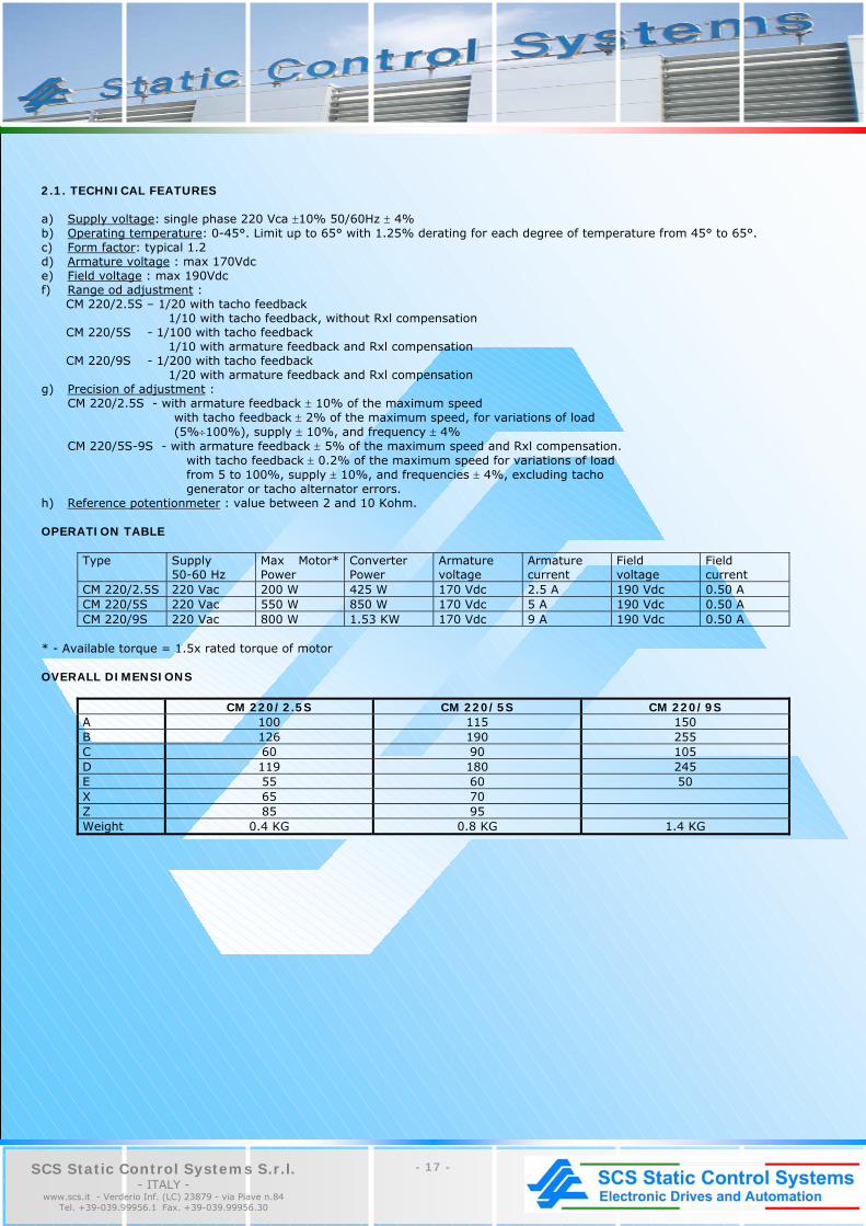
2.1. TECHNICAL FEATURES a) Supply voltage: single phase 220 Vca ±10% 50/60Hz ± 4% b) Operating temperature: 0-45°. Limit up to 65° with 1.25% derating for each degree of temperature from 45° to 65°. c) Form factor: typical 1.2 d) Armature voltage : max 170Vdc e) Field voltage : max 190Vdc f) Range od adjustment : CM 220/2.5S – 1/20 with tacho feedback 1/10 with tacho feedback, without Rxl compensation CM 220/5S - 1/100 with tacho feedback 1/10 with armature feedback and Rxl compensation CM 220/9S - 1/200 with tacho feedback 1/20 with armature feedback and Rxl compensation g) Precision of adjustment :
CM 220/2.5S - with armature feedback ± 10% of the maximum speed with tacho feedback ± 2% of the maximum speed, for variations of load (5%÷100%), supply ± 10%, and frequency ± 4% CM 220/5S-9S - with armature feedback ± 5% of the maximum speed and Rxl compensation. with tacho feedback ± 0.2% of the maximum speed for variations of load from 5 to 100%, supply ± 10%, and frequencies ± 4%, excluding tacho generator or tacho alternator errors.
h) Reference potentionmeter : value between 2 and 10 Kohm. OPERATION TABLE
Type Supply 50-60 Hz
Max Motor* Power
Converter Power
Armature voltage
Armature current
Field voltage
Field current
CM 220/2.5S 220 Vac 200 W 425 W 170 Vdc 2.5 A 190 Vdc 0.50 A CM 220/5S 220 Vac 550 W 850 W 170 Vdc 5 A 190 Vdc 0.50 A CM 220/9S 220 Vac 800 W 1.53 KW 170 Vdc 9 A 190 Vdc 0.50 A
* - Available torque = 1.5x rated torque of motor OVERALL DIMENSIONS
CM 220/2.5S CM 220/5S CM 220/9S A 100 115 150 B 126 190 255 C 60 90 105 D 119 180 245 E 55 60 50 X 65 70 Z 85 95 Weight 0.4 KG 0.8 KG 1.4 KG
- 18 - SCS Static Control Systems S.r.l. - ITALY -
www.scs.it - Verderio Inf. (LC) 23879 - via Piave n.84 Tel. +39-039.99956.1 Fax. +39-039.99956.30
CH220 - CH22 UNIDIRECTIONAL MOSFET DRIVE
ST EUROCARD SERIES TRANSISTOR PWM SERVO AMPLIFIER
SM EUROCARD E1 SERIES MOSFET PWM SERVO AMPLIFIERS

- 19 - SCS Static Control Systems S.r.l. - ITALY -
www.scs.it - Verderio Inf. (LC) 23879 - via Piave n.84 Tel. +39-039.99956.1 Fax. +39-039.99956.30
CH220 - CH22 UNIDIRECTIONAL MOSFET DRIVE CHARACTERISTICS CH220 and CH22 are unidirectional drives, which use mosfets as power elements. These drives are suitable for driving low power motors at wound field or highly efficient permanent magnets motors. They are available in the standard version to be connected to 110/220±20% 50-60Hz single -phase net, protected by extrarapid fuses (on request also the version 24/48V±10% is available). The high commutation frequency (16KHz for CH220 and 10KHz for CH22) allows to obtain a very good form factor, even without using armature inductance. CH220 is available in three current sizes from 3 to 10A nominal with peak current of 150% of the nominal for 30 sec. and is able to drive motors with powers till 2Kw. CH22 is available in only one size with nominal current of 3.3A and peak current of 5A and is able to drive motors with max. power of 0.55Kw. Both families of products are manufactured in accordance with the product standard for power electronics EN 60146-1-1. Concerning the electromagnetical compatibility (EMC), CH220 and CH22 are immune from electromagnetical interferences in industrial environment in accordance with EN 50082-2 and respect the emission specifications in industrial environment in accordance with EN 50081-2 if they are coupled to an external filter and correctly installed in a system, as stated in the instruction manual.
Type
CH22-03
Nominal current
3.3A
Max. current
5A adjustable with jumper
Main voltage and frequency
1~220/110V±20% 50/60 Hz
Nominal temperature
0÷ +40°C
Protection grade
IP00 (IP20 on request)
Analog inputs
No. 1 reference
Logic inputs
Enabling input
Logic outputs Contact N.O. Zero speed
Signaling leds
Power ON
Trimming potentiometers Stability Max. speed Ramp Min. speed
Dimensions [mm] (front view)
L=190 H=115 D=80

- 20 - SCS Static Control Systems S.r.l. - ITALY -
www.scs.it - Verderio Inf. (LC) 23879 - via Piave n.84 Tel. +39-039.99956.1 Fax. +39-039.99956.30
Type
CH220-03G CH220-06G CH220-10G
Dimensions [mm] (front view)
L=190 H=100 D=67
L=180 H=100 D=80
L=180 H=100 D=80
Nominal current 3A
6A 10A
Peak current 150% of the nominal current with automatic return (electronicthermic relay)
Main voltage and frequency ~ 220/110V±10% 50/60Hz
Protection grade IP00 (IP20 on request) Rack version on request
Nominal Temperature 0÷ +45°C
Options Zero speed relay (CH-NO)
Galvanic insulation (CH-GI)
Analog inputs No. 1 main reference
Logic inputs Enabling input
Logic outputs Driver OK Contact N.O. zero speed
Signaling leds Power ON Power alarm Electronic thermic intervention Zero speed
Trimming potentiometers Stability Max. speed Min. speed No. 2 speed ramps Current limit RXI compensation Zero speed
Protections Low value of armature inductance Load short circuit Equalization condensers degradation Tachymetric dynamo inversion Heatsink overtemp. (only 6 and 10A)

- 21 - SCS Static Control Systems S.r.l. - ITALY -
www.scs.it - Verderio Inf. (LC) 23879 - via Piave n.84 Tel. +39-039.99956.1 Fax. +39-039.99956.30
ST EUROCARD E1 ST SERIES TRANSISTOR PWM SERVO AMPLIFIER FOR D.C. MOTORS GENERAL • Single axis version incorporating power supply and clamp
circuit • Rack or panel mounting • Optimum quality, size and cost ratio • Compact design 3U/14TE FEATURES • 2KHz four quadrant PWM operation • Motor voltage range from 10 to 80V • Continuous current up to 4A • Peak current up to 8A • Internal armature feedback • Thermal image and current limit • Differential reference input • 3 LED status indicators
Removable calibration board with surface mounting technology (smt)
MAIN FEATURES The SCS Servocontrol of the ST series has been designed to drive small power, high performance permanent magnet motors. It features four quadrant reversible operation, while its internal clamp circuit ensures dissipation of inertial deceleration energy. The built-in fuse cuts off the power supply from the power bridge in the event of faults or short circuits. The series ST Servocontrol is part of a system consisting of: • Servo amplifier: in open-frame or connector version • Minimum inductance: to guarantee a form factor of 1.005 • Single phase transformer with central socket: required for supplying the power and control circuits. • Connector board RK16: for version with DIN 41612 connector; output with terminal board and PC board holder guides. The following table gives details of the entire system supplied by SCS plus relative order codes:
Converter
Armature current
Type
Transformer drop ≤ 5%
Minimum inductance
Nominal voltage IN IP
Type Pow.W Va.c. Type mH IT IS V A
ST 24 – 4 ST 48 – 4 ST 65 – 4 ST 80 – 4
TR01 TR02 TR03 TR04
200 350 475 580
25 42 57 66
L01 L02 L03 L04
5 9
11 14
5 5 5 5
9 9 9 9
24 48 65 80
4 4 4 4
8 8 8 8
N.B.: To obtain the max r.p.m. at nominal torque (I nom.), decrease the max motor voltages by the percentage no-load/load drop of the transformer, which is 5-6% on the average. ADJUSTMENT TRIMMERS:
Maximum speed: through Nmax [P1] Maximum current: through IP [P2] Nominal current: through IN [P3] Offset: through AZZ [P4] Stability: through STAB [P5]
LED STATUS INDICATORS LD1 (red) OK External enable LD2 (red) l2t Thermal image intervention LD3 (red) ± 15V Voltages present
GENERAL RULES
(Italian D.P.R. n.224 dated 24/05/88 – EEC Directive n.374/85) This equipment should only be used, installed and adjusted by specialized and qualified personnelwho are familiar with the construction and operation of both system and equipment, on the basis of the technical specifications of the product. All the necessary precautions should be taken in the system where the product is used in order to safeguard the operator in the event of equipment failure.

SCS Static Control Systems S.r.l. - ITALY -
(Milan Area)
23879 - via Piave n.84 Verderio Inferiore (LC) Tel. +39-039.99956.1
Fax. +39-039.99956.30 [email protected] - www.scs.it