Embed Size (px)
Citation preview
400
JIS symbol
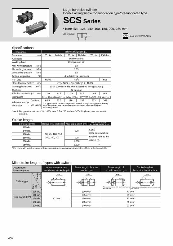
Large bore size cylinderDouble acting/single rod/lubrication type/pre-lubricated type
SCS Series• Bore size: 125, 140, 160, 180, 200, 250 mm
SpecificationsDescriptions SCS/SCS-N/SCS-LN
Bore size mm
Actuation
Working fluid
Max. working pressure MPa
Min. working pressure MPa
Withstanding pressure MPa
Ambient temperature °CPort size
Stroke tolerance (Note 1) mm
Working piston speed mm/s
Cushion
Effective cushion length mm
Lubrication
Cushioned
Non cushion
250 dia.
Rc1
26.6
362
200 dia.
26.6
233
180 dia.
21.6
152
160 dia.
21.6
116
Double acting
Compressed air
1.0
0.05
1.6
-5 to 60 (to be unfrozen)
Rc /
(to 300), (to 500), (to 1000)
20 to 1000 (use this within absorbed energy range.)
Air cushion
Required (when lubrication, use turbine oil Class 1 ISO VG32), For SCS- N/LN, not required
140 dia.
21.6
91.5
125 dia.
Rc /
21.6
63.5
+1.00
+1.40
+1.40
1 23
4
* For types with switch, minimum stroke varies depending on installation method. Refer to the below table.
Note 1: For type with switches (to 1000), Note 2: For 250 mm bore SCS-LN cylinder, switches are not available.
Stroke lengthBore size (mm)
125 dia.
140 dia.
160 dia.
180 dia.
200 dia.
250 dia.
Standard stroke length (mm) Max. stroke length (mm)
800
900
1,000
1,200
50, 75, 100, 150,
200, 250, 300
When with switch, min. stroke length (mm)*
20(10)
When one switch is
installed, refer to the
value in ( ).
+2.0 0
Min. stroke length of types with switch
20 over
125 dia.
140 dia.
160 dia.
180 dia.
200 dia.
120 over
125 over
130 over
135 over
140 over
The position at rod side stroke end cannot be detected.
The position at head side stroke end cannot be detected.
When same surfaceinstallation, stroke length
DescriptionsBore size (mm)
Switch type
Rou
ghsk
etch
Bor
esi
ze
Reed switch (R *)
Stroke length of center trunnion type
Stroke length of rod side trunnion type
Stroke length of head side trunnion type
70 over
75 over
80 over
85 over
90 over
Port PortPort Port
The types without cushioning cannot absorb a large energy generated by an external load. We recommend installation of an external shock absorbing device.
Allowable energy
absorption J
CAD DATA AVAILABLE.
401
Standard type
Larg
e bo
re size cylind
er
SCP * 2
CMK2
CMA2
SCM
SCA2
SCS
CKV2
CAT
MDC2
MVC
SMD2
SSD
FC *
JSB3
UCAC
LCS
LCY
STR2
UCA2
STK
USSD
USC
MFC
GLC
SHC
CAC3
HCM
HCA
MRL2
SRL2
SRG
SRM
SRT
SRB2
CAV2/COV * 2
MSD/MSDG
ULKP/ULKJSK2/JSM2
STS/STL
SSD (large)
JSC3 (medium)JSC3 (large)
SCS Series
Specifications
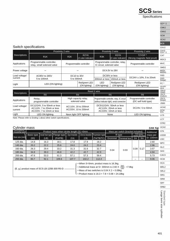
Cylinder mass
Axial foot type
(LB)
125 dia.
140 dia.
160 dia.
180 dia.
200 dia.
250 dia.
Additional mass per S= 100mmBore size (mm)
Descriptions/mounting style Product mass when stroke length (S) =0mm Mass per switch (bracket included)
16.3
22.2
29.4
39.3
53.3
92.1
Basic type
(00)
14.8
20.2
26.3
34.8
47.6
83.7
Flange type
(FA/FB)
18.1
25.6
33.2
46.8
61.3
109.6
Eye bracket
(CA)
17.8
24.0
31.3
42.2
57.1
107.7
Clevis bracket
(CB)
17.9
24.2
31.6
42.7
57.3
102.2
Trunnion type
(TA/TB/TC)
18.2
23.4
32.7
42.9
59.4
112.4
Grommet
0.04
Terminal box
0.03
T2YD (strong magnetic field proof)R type
0.09
1m 3m
0.17
- -
2.60
2.96
3.57
4.94
5.73
9.06
(Unit: Kg)(Unit: Kg)
(E. g.) product mass of SCS-LB-125B-300-R0-D
• When S=0mm, product mass is 16.3kg.
• Additional mass at S= 300mm is 2.60 X =7.8kg
• Mass of two switches is 0.04 X 2 = 0.08kg.
• Product mass is 16.3 + 7.8 + 0.08 = 24.18kg
300100
Note: Please refer to Ending 1 about other switch specifications.
R1K
R0 R4 R5 R6
LED ON lighting Neon light OFF lighting None LED ON lighting
DC12/24V, 5 to 50mA or lessAC110V, 7 to 20mA or lessAC220V, 7 to 10mA or less
AC110V, 20 to 200mAAC220V, 10 to 200mA
DC5/12/24V, 50mA or lessAC110V, 20mA or lessAC220V, 10mA or less
DC24V, 5 to 50mA
High capacity relay, solenoid valve
Relay, programmable controller
Programmable controller, relay, IC circuit (without indicator light), serial connection
Programmable controller(DC self hold type)
Applications
Power voltage
Load voltage/current
Light
Applications
Load voltage/
current
Light
R2KR2YK
(2 color indicator)
Red/green LED(ON lighting)
R3KR3YK
(2 color indicator)
200mA or less 150mA or less
T2YDP *(Strong magnetic field proof)
LED (ON lighting)LED
(ON lighting)Red/green LED
(ON lighting)Red/green LED
(ON lighting)
AC85V to 265V5 to 100mA
DC10 to 30V5 to 300mA DC24V ± 10%, 5 to 20mA
Programmable controller, relay, small solenoid valve Programmable controller
Programmable controller, relay, IC circuit, solenoid valve Programmable controller
- - DC4.5V to 28V
DC30V or less
-
Switch specifications
Descriptions
Proximity 2 wire Proximity 3 wire Proximity 2 wire
Reed 2 wireDescriptions
402
A
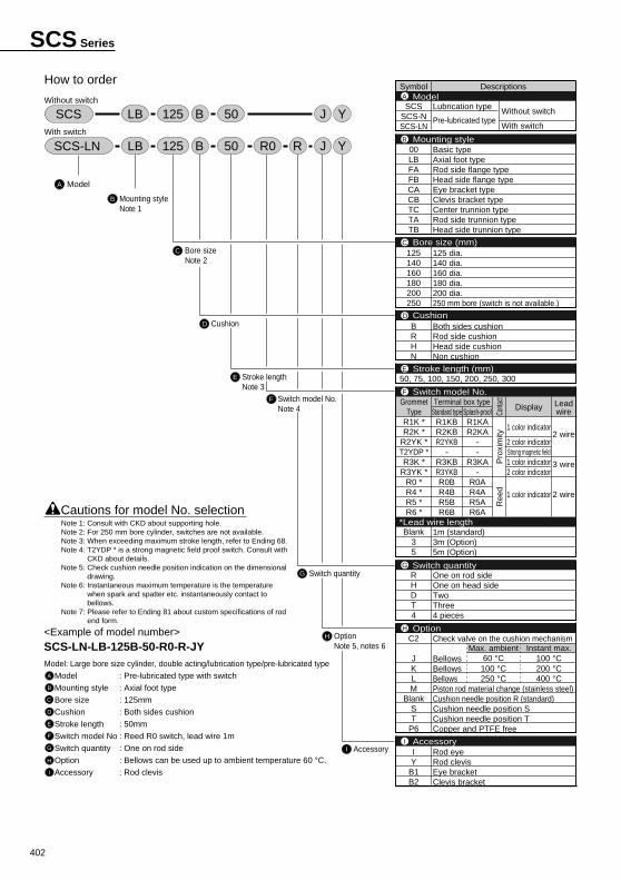
How to order
Without switch
With switch
Model
B Mounting styleNote 1
C Bore sizeNote 2
D Cushion
F Switch model No.Note 4
E Stroke lengthNote 3
G Switch quantity
I Accessory
H OptionNote 5, notes 6
<Example of model number>SCS-LN-LB-125B-50-R0-R-JYModel: Large bore size cylinder, double acting/lubrication type/pre-lubricated type
Model : Pre-lubricated type with switch
Mounting style : Axial foot type
Bore size : 125mm
Cushion : Both sides cushion
Stroke length : 50mm
Switch model No : Reed R0 switch, lead wire 1m
Switch quantity : One on rod side
Option : Bellows can be used up to ambient temperature 60 °C.
Accessory : Rod clevis
A
B
C
D
E
F
G
H
I
Cautions for model No. selection
SCS-LN LB 125 JRB YR050
SCS LB 125 JB Y50
Symbol Descriptions
SCSSCS-NSCS-LN
00LBFAFBCACBTCTATB
125140160180200250
BRHN
Blank35
RHDT4
C2
JKLM
BlankST
P6
IYB1B2
ModelA
Mounting styleB
Bore size (mm)C
CushionD
Stroke length (mm)E
Switch model No.F
Switch quantityG
OptionH
AccessoryI
*Lead wire length
Leadwire
2 wire
3 wire
2 wireCo
ntact
Pro
xim
ityR
eed
Terminal box typeDisplay
1 color indicator
2 color indicatorStrong magnetic field1 color indicator2 color indicator
1 color indicator
Lubrication type
Pre-lubricated type
Basic typeAxial foot typeRod side flange typeHead side flange typeEye bracket typeClevis bracket typeCenter trunnion typeRod side trunnion typeHead side trunnion type
125 dia.140 dia.160 dia.180 dia.200 dia.250 mm bore (switch is not available.)
Both sides cushionRod side cushionHead side cushionNon cushion
1m (standard)3m (Option)5m (Option)
One on rod sideOne on head sideTwoThree4 pieces
Check valve on the cushion mechanism
BellowsBellowsBellowsPiston rod material change (stainless steel)Cushion needle position R (standard)Cushion needle position SCushion needle position TCopper and PTFE free
Rod eyeRod clevisEye bracketClevis bracket
Without switch
With switch
50, 75, 100, 150, 200, 250, 300
Standard typeR1KBR2KBR2YKB
-R3KBR3YKBR0BR4BR5BR6B
Splash-proofR1KAR2KA
--
R3KA-
R0AR4AR5AR6A
GrommetType
R1K *R2K *
R2YK *T2YDP *R3K *
R3YK *R0 *R4 *R5 *R6 *
Max. ambient60 °C100 °C250 °C
Instant max.100 °C200 °C400 °C
Note 1: Consult with CKD about supporting hole.Note 2: For 250 mm bore cylinder, switches are not available.Note 3: When exceeding maximum stroke length, refer to Ending 68.Note 4: T2YDP * is a strong magnetic field proof switch. Consult with
CKD about details.Note 5: Check cushion needle position indication on the dimensional
drawing.Note 6: Instantaneous maximum temperature is the temperature
when spark and spatter etc. instantaneously contact to bellows.
Note 7: Please refer to Ending 81 about custom specifications of rod end form.
SCS Series
403
Standard type
Larg
e bo
re size cylind
er
SCP * 2
CMK2
CMA2
SCM
SCA2
SCS
CKV2
CAT
MDC2
MVC
SMD2
SSD
FC *
JSB3
UCAC
LCS
LCY
STR2
UCA2
STK
USSD
USC
MFC
GLC
SHC
CAC3
HCM
HCA
MRL2
SRL2
SRG
SRM
SRT
SRB2
CAV2/COV * 2
MSD/MSDG
ULKP/ULKJSK2/JSM2
STS/STL
SSD (large)
JSC3 (medium)JSC3 (large)
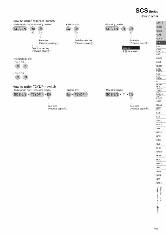
Switch model No.(Previous page )
How to order discrete switch• Switch main body + mounting bracket
SCS-LN R0 125C
C F
F
F
Bore size(Previous page )
C
CBore size(Previous page )
Switch model No.(Previous page )
• Mounting bracket
SCS-LN 125RC
CBore size(Previous page )
Bracket
R R type switch
• Switch only
SW R0F
C
C
Bore size(Previous page )
How to order T2YDP * switch• Switch main body + mounting bracket
T2YDP * 125• Mounting bracket
SCS-LN 125T• Switch only
SWSCS-LN T2YDP *
• Terminal box only • For R * B
SW RB
• For R * A
SW RA
SCS Series
How to order
404
Bore size (mm) Kit number Repair parts number
125 dia.
140 dia.
160 dia.
180 dia.
200 dia.
250 dia.
SCS-125K
SCS-140K
SCS-160K
SCS-180K
SCS-200K
SCS-250K
2 3 5 7 8
14 22
2 3 5 7 8
14 22
Bore size (mm) Kit number Repair parts number
125 dia.
140 dia.
160 dia.
180 dia.
200 dia.
250 dia.
SCS-N-125K
SCS-N-140K
SCS-N-160K
SCS-N-180K
SCS-N-200K
SCS-N-250K
27
27
2 3 5 7 8
14 22 27
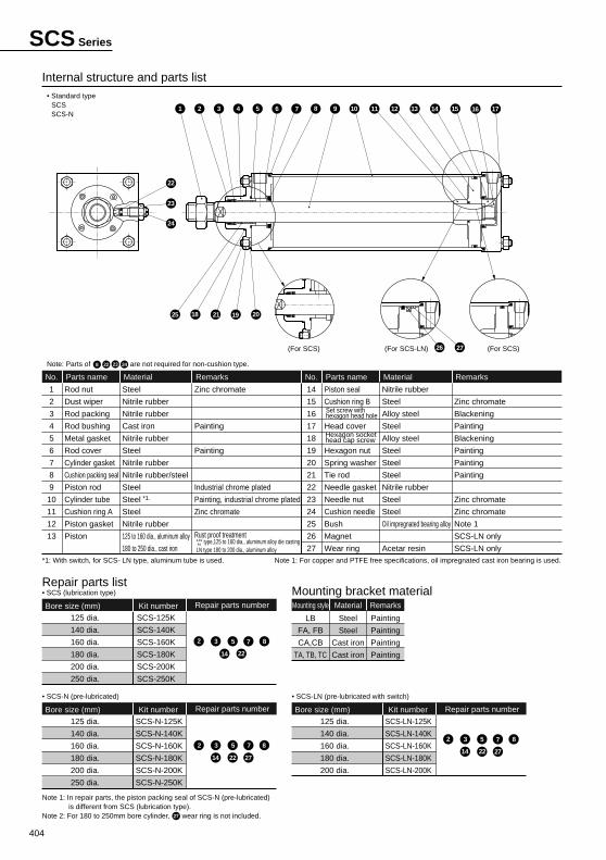
Internal structure and parts list
1
2
3
4
5
6
7
8
9
10
11
12
13
Rod nut
Dust wiper
Rod packing
Rod bushing
Metal gasket
Rod cover
Cylinder gasket
Cushion packing seal
Piston rod
Cylinder tube
Cushion ring A
Piston gasket
Piston
*1.
Parts name
Steel
Nitrile rubber
Nitrile rubber
Cast iron
Nitrile rubber
Steel
Nitrile rubber
Nitrile rubber/steel
Steel
Steel
Steel
Nitrile rubber
125 to 160 dia., aluminum alloy
180 to 250 dia., cast iron
Material
Zinc chromate
Painting
Painting
Industrial chrome plated
Painting, industrial chrome plated
Zinc chromate
Rust proof treatment type,125 to 160 dia., aluminum alloy die casting LN type 180 to 200 dia., aluminum alloy
Remarks
Zinc chromate
Blackening
Painting
Blackening
Painting
Painting
Painting
Zinc chromate
Zinc chromate
Note 1
SCS-LN only
SCS-LN only
No.
14
15
16
17
18
19
20
21
22
23
24
25
26
27
Piston seal
Cushion ring B
Head cover
Hexagon nut
Spring washer
Tie rod
Needle gasket
Needle nut
Cushion needle
Bush
Magnet
Wear ring
Parts name
Nitrile rubber
Steel
Alloy steel
Steel
Alloy steel
Steel
Steel
Steel
Nitrile rubber
Steel
Steel
Oil impregnated bearing alloy
Acetar resin
Material RemarksNo.
*1: With switch, for SCS- LN type, aluminum tube is used. Note 1: For copper and PTFE free specifications, oil impregnated cast iron bearing is used.
Repair parts list
• SCS-N (pre-lubricated)
• SCS (lubrication type) Mounting bracket material
LB
FA, FB
CA,CB
TA, TB, TC
Mounting style
Steel
Steel
Cast iron
Cast iron
Material
Painting
Painting
Painting
Painting
Remarks
• Standard typeSCSSCS-N
Note: Parts of are not required for non-cushion type.
LNN
Note 1: In repair parts, the piston packing seal of SCS-N (pre-lubricated) is different from SCS (lubrication type).
Note 2: For 180 to 250mm bore cylinder, wear ring is not included.
Bore size (mm) Kit number Repair parts number
125 dia.
140 dia.
160 dia.
180 dia.
200 dia.
SCS-LN-125K
SCS-LN-140K
SCS-LN-160K
SCS-LN-180K
SCS-LN-200K
• SCS-LN (pre-lubricated with switch)
Set screw with hexagon head hole
Hexagon socket head cap screw
22 24238
(For SCS) (For SCS-LN) (For SCS)
6 981 102
22
23
24
74 53 11 12 13 14 15 16 17
25 18 21 19 20
26 27
SCS Series
405
Standard type
Larg
e bo
re size cylind
er
SCP * 2
CMK2
CMA2
SCM
SCA2
SCS
CKV2
CAT
MDC2
MVC
SMD2
SSD
FC *
JSB3
UCAC
LCS
LCY
STR2
UCA2
STK
USSD
USC
MFC
GLC
SHC
CAC3
HCM
HCA
MRL2
SRL2
SRG
SRM
SRT
SRB2
CAV2/COV * 2
MSD/MSDG
ULKP/ULKJSK2/JSM2
STS/STL
SSD (large)
JSC3 (medium)JSC3 (large)
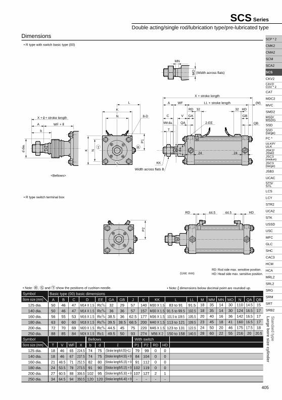
• R type with switch basic type (00)
• R type switch terminal box
(Unit: mm)
Dimensions
RD: Rod side max. sensitive position.HD: Head side max. sensitive position.
50
50
56
63
72
88
A
46
46
55
60
70
85
B
M14 X 1.5
M14 X 1.5
M16 X 1.5
M18 X 1.5
M20 X 1.5
M24 X 1.5
D
47
47
53
60
69
84
C
Rc /
Rc /
Rc /
Rc /
Rc /
Rc1
EE
32
36
38.5
39.5
44.5
49.5
GA
29
36
36
38.5
45
50
GB
57
57
62.5
68.5
75
93
J
140
157
177
200
220
274
K
M30 X 1.5
M30 X 1.5
M36 X 1.5
M40 X 1.5
M45 X 1.5
M56 X 2
KK
83 to 91
91.5 to 99.5
101.5 to 109.5
113 to 121
123 to 131
150 to 158
L
91.5
102.5
105.5
109.5
122.5
140.5
LL35
35
40
45
50
60
MM14
14
16
18
20
22
MN18
18
20
23
24
28
M30
30
36
41
46
55
MO110
124
142
160
175
216
N14.5
16.5
16.5
16.5
17.5
20
QA15
17
17
17
18
20.5
QB
18
18
21
24
27
34
T
46
46
48.5
53.5
60.5
64.5
V
224.5
237.5
252.5
273.5
306.5
350.5
X
65
67
71
78
88
94
WF
74
74
82
91
102
120
b
75
75
80
90
95
120
d(Stroke length/4.55)+11
(Stroke length/4.55) + 9
(Stroke length/5.15) + 9
(Stroke length/5.15) + 9
(Stroke length/5.30) + 9
(Stroke length/6.40) + 9
Basic type (00) basic dimensions
125 dia.
140 dia.
160 dia.
180 dia.
200 dia.
250 dia.
Symbol
Bore size (mm)
125 dia.
140 dia.
160 dia.
180 dia.
200 dia.
250 dia.
Bellows
79
84
91
102
107
-
P1
99
104
112
119
127
-
P2
0
0
0
0
2
-
RD
0
0
0
0
1
-
HD
With switchSymbol
Bore size (mm)
• Note: dimensions below decimal point are rounded up.
1
3
3
3
3
2
4
4
4
4
• Note: R , S and T show the positions of cushion needle.
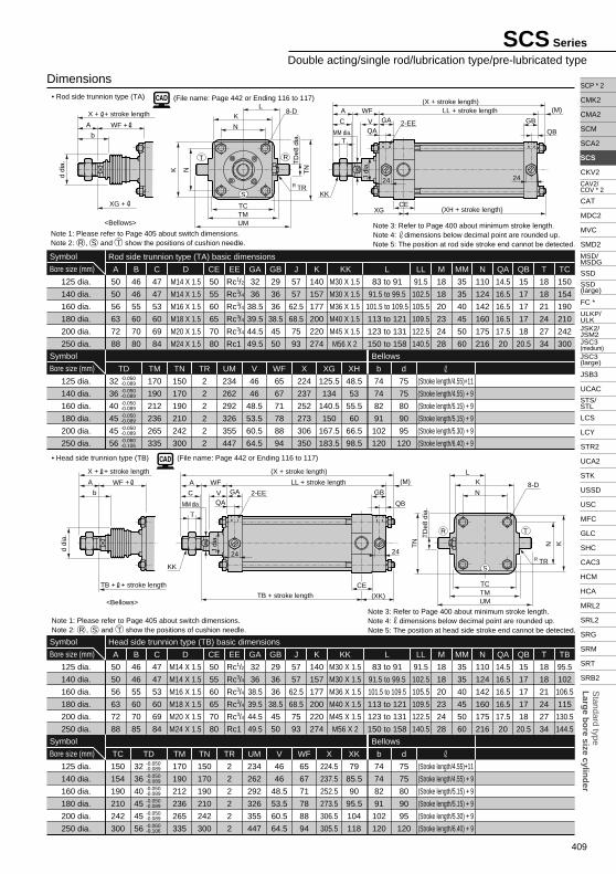
SCS Series
Double acting/single rod/lubrication type/pre-lubricated type
RD HD
P2
44.5 44.5
d di
a.
X + + stroke length
<Bellows>
WF +A
b
MN
MO (Width across flats)
RD HD
P1
J di
a.
32 32
K N
QA 2-EE
V GA
MM dia.
Width across flats B
KK
C GB
24 24
QB
A WF (M)LL + stroke length
X + stroke length
T
K
N
L
T
S
R
8-D
406
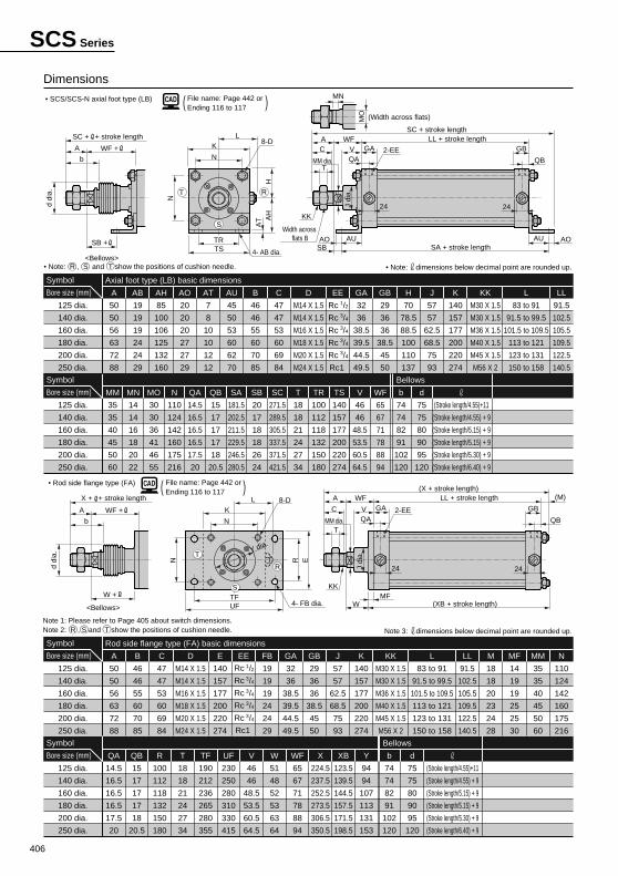
File name: Page 442 or Ending 116 to 117( )
File name: Page 442 or Ending 116 to 117( )
• SCS/SCS-N axial foot type (LB)
Dimensions
• Rod side flange type (FA)
50
50
56
63
72
88
A
46
46
55
60
70
85
B
M14 X 1.5
M14 X 1.5
M16 X 1.5
M18 X 1.5
M20 X 1.5
M24 X 1.5
D
47
47
53
60
69
84
C
140
157
177
200
220
274
E EE
19
19
19
24
24
29
FB
32
36
38.5
39.5
44.5
49.5
GA
29
36
36
38.5
45
50
GB
57
57
62.5
68.5
75
93
J
140
157
177
200
220
274
K
M30 X 1.5
M30 X 1.5
M36 X 1.5
M40 X 1.5
M45 X 1.5
M56 X 2
KK
83 to 91
91.5 to 99.5
101.5 to 109.5
113 to 121
123 to 131
150 to 158
L
91.5
102.5
105.5
109.5
122.5
140.5
LL
14
19
19
25
25
30
MF
18
18
20
23
24
28
M
35
35
40
45
50
60
MM
110
124
142
160
175
216
N
14.5
16.5
16.5
16.5
17.5
20
QA
15
17
17
17
18
20.5
QB
100
112
118
132
150
180
R
18
18
21
24
27
34
T
190
212
236
265
280
355
TF
230
250
280
310
330
415
UF
46
46
48.5
53.5
60.5
64.5
V
51
48
52
53
63
64
W
65
67
71
78
88
94
WF
224.5
237.5
252.5
273.5
306.5
350.5
X
123.5
139.5
144.5
157.5
171.5
198.5
XB
94
94
107
113
131
153
Y
74
74
82
91
102
120
b
75
75
80
90
95
120
d
(Stroke length/4.55)+11
(Stroke length/4.55) + 9
(Stroke length/5.15) + 9
(Stroke length/5.15) + 9
(Stroke length/5.30) + 9
(Stroke length/6.40) + 9
Rod side flange type (FA) basic dimensions
125 dia.
140 dia.
160 dia.
180 dia.
200 dia.
250 dia.
Symbol
Bore size (mm)
125 dia.
140 dia.
160 dia.
180 dia.
200 dia.
250 dia.
BellowsSymbol
Bore size (mm)
Note 3: dimensions below decimal point are rounded up.
Rc /
Rc /
Rc /
Rc /
Rc /
Rc1
1
3
3
3
3
2
4
4
4
4
50
50
56
63
72
88
A
19
19
19
24
24
29
AB
85
100
106
125
132
160
AH
20
20
20
27
27
29
AO
7
8
10
10
12
12
AT
45
50
53
60
62
70
AU
46
46
55
60
70
85
B
M14 X 1.5
M14 X 1.5
M16 X 1.5
M18 X 1.5
M20 X 1.5
M24 X 1.5
D
47
47
53
60
69
84
C
Rc /
Rc /
Rc /
Rc /
Rc /
Rc1
EE
32
36
38.5
39.5
44.5
49.5
GA
29
36
36
38.5
45
50
GB
70
78.5
88.5
100
110
137
H
57
57
62.5
68.5
75
93
J
140
157
177
200
220
274
K
M30 X 1.5
M30 X 1.5
M36 X 1.5
M40 X 1.5
M45 X 1.5
M56 X 2
KK
83 to 91
91.5 to 99.5
101.5 to 109.5
113 to 121
123 to 131
150 to 158
L
91.5
102.5
105.5
109.5
122.5
140.5
LL
35
35
40
45
50
60
MM
14
14
16
18
20
22
MN
30
30
36
41
46
55
MO
110
124
142
160
175
216
N
14.5
16.5
16.5
16.5
17.5
20
QA
15
17
17
17
18
20.5
QB
181.5
202.5
211.5
229.5
246.5
280.5
SA
20
17
18
18
26
24
SB
271.5
289.5
305.5
337.5
371.5
421.5
SC
18
18
21
24
27
34
T
100
112
118
132
150
180
TR
140
157
177
200
220
274
TS
46
46
48.5
53.5
60.5
64.5
V
65
67
71
78
88
94
WF
74
74
82
91
102
120
b
75
75
80
90
95
120
d
(Stroke length/4.55)+11
(Stroke length/4.55) + 9
(Stroke length/5.15) + 9
(Stroke length/5.15) + 9
(Stroke length/5.30) + 9
(Stroke length/6.40) + 9
Axial foot type (LB) basic dimensions
125 dia.
140 dia.
160 dia.
180 dia.
200 dia.
250 dia.
Symbol
Bore size (mm)
125 dia.
140 dia.
160 dia.
180 dia.
200 dia.
250 dia.
BellowsSymbol
Bore size (mm)
• Note: dimensions below decimal point are rounded up.
1
3
3
3
3
2
4
4
4
4
• Note: R , S and T show the positions of cushion needle.
Note 1: Please refer to Page 405 about switch dimensions.Note 2: R , S and T show the positions of cushion needle.
d di
a.
X + + stroke length
<Bellows>
WF +A
b
W +
MM dia.
J di
a.
4- FB dia.
8-D2-EE
KK
A WF
T
24 24
C GAL
V
LL + stroke length(X + stroke length)
(XB + stroke length)
K
N
TF
Y dia.
UF
ERN
WMF
QA
GB
(M)
QB
T
S
R
SCS Seriesd
dia.
SC + + stroke length
WF +A
b
SB +
MM dia.
J di
a.
4- AB dia.
8-D2-EE
KK
Width across flats B
A WF
T
24 24
C GA
L
VLL + stroke length
SC + stroke length
SA + stroke length
K
N
TRTS
HA
HA
T
SBAO AU AOAU
QA
GB
QBN
MN
MO (Width across flats)
T
S
R
<Bellows>
407
Standard type
Larg
e bo
re size cylind
er
SCP * 2
CMK2
CMA2
SCM
SCA2
SCS
CKV2
CAT
MDC2
MVC
SMD2
SSD
FC *
JSB3
UCAC
LCS
LCY
STR2
UCA2
STK
USSD
USC
MFC
GLC
SHC
CAC3
HCM
HCA
MRL2
SRL2
SRG
SRM
SRT
SRB2
CAV2/COV * 2
MSD/MSDG
ULKP/ULKJSK2/JSM2
STS/STL
SSD (large)
JSC3 (medium)JSC3 (large)
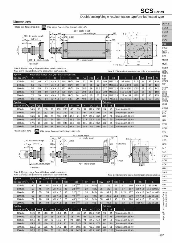
(File name: Page 442 or Ending 116 to 117)
(File name: Page 442 or Ending 116 to 117)• Head side flange type (FB)
50
50
56
63
72
88
A
46
46
55
60
70
85
B
M14 X 1.5
M14 X 1.5
M16 X 1.5
M18 X 1.5
M20 X 1.5
M24 X 1.5
D
47
47
53
60
69
84
C
140
157
177
200
220
274
E
19
19
19
24
24
29
FB
32
36
38.5
39.5
44.5
49.5
GA
29
36
36
38.5
45
50
GB
57
57
62.5
68.5
75
93
J
140
157
177
200
220
274
K
M30 X 1.5
M30 X 1.5
M36 X 1.5
M40 X 1.5
M45 X 1.5
M56 X 2
KK
83 to 91
91.5 to 99.5
101.5 to 109.5
113 to 121
123 to 131
150 to 158
L
91.5
102.5
105.5
109.5
122.5
140.5
LL
14
19
19
25
25
30
MF
35
35
40
45
50
60
MM
110
124
142
160
175
216
N
14.5
16.5
16.5
16.5
17.5
20
QA
15
17
17
17
18
20.5
QB
100
112
118
132
150
180
R
18
18
21
24
27
34
T
190
212
236
265
280
355
TF
230
250
280
310
330
415
UF
46
46
48.5
53.5
60.5
64.5
V
65
67
71
78
88
94
WF
94
94
107
113
131
153
Y b
74
74
82
91
102
120
75
75
80
90
95
120
d
220.5
238.5
251.5
275.5
307.5
52.5
ZC
170.5
188.5
195.5
212.5
235.5
264.5
ZR
Head side flange type (FB) basic dimensions
125 dia.
140 dia.
160 dia.
180 dia.
200 dia.
250 dia.
Symbol
Bore size (mm)
125 dia.
140 dia.
160 dia.
180 dia.
200 dia.
250 dia.
BellowsSymbol
Bore size (mm)
Note 1: Please refer to Page 405 about switch dimensions.Note 2: R , S and T show the positions of cushion needle. Note 3: dimensions below decimal point are rounded up.
EE
Rc /
Rc /
Rc /
Rc /
Rc /
Rc1
1
3
3
3
3
2
4
4
4
4
(Stroke length/4.55)+11
(Stroke length/4.55) + 9
(Stroke length/5.15) + 9
(Stroke length/5.15) + 9
(Stroke length/5.30) + 9
(Stroke length/6.40) + 9
Dimensions
50
50
56
63
72
88
A
46
46
55
60
70
85
B
M14 X 1.5
M14 X 1.5
M16 X 1.5
M18 X 1.5
M20 X 1.5
M24 X 1.5
D
47
47
53
60
69
84
C
35
40
40
55
55
65
CC CD
20
22
24
25
30
35
CF EE
32
36
40
50
50
63
EW
32
36
38.5
39.5
44.5
49.5
GA
29
36
36
38.5
45
50
GB
57
57
62.5
68.5
75
93
J
140
157
177
200
220
274
K
M30 X 1.5
M30 X 1.5
M36 X 1.5
M40 X 1.5
M45 X 1.5
M56 X 2
KK
83 to 91
91.5 to 99.5
101.5 to 109.5
113 to 121
123 to 131
150 to 158
L
Eye bracket (CA) basic dimensions
125 dia.
140 dia.
160 dia.
180 dia.
200 dia.
250 dia.
Symbol
Bore size (mm)
91.5
102.5
105.5
109.5
122.5
140.5
LL
35
35
40
45
50
60
MM
110
124
142
160
175
216
N
25
28
32
40
40
50
MR
14.5
16.5
16.5
16.5
17.5
20
QA
15
17
17
17
18
20.5
QB
18
18
21
24
27
34
T
46
46
48.5
53.5
60.5
64.5
V
65
67
71
78
88
94
WF
294.5
322.5
339.5
380.5
412.5
482.5
XC
219.5
244.5
251.5
277.5
300.5
344.5
XD
74
74
82
91
102
120
b
75
75
80
90
95
120
d
(Stroke length/4.55)+11
(Stroke length/4.55) + 9
(Stroke length/5.15) + 9
(Stroke length/5.15) + 9
(Stroke length/5.30) + 9
(Stroke length/6.40) + 9
125 dia.
140 dia.
160 dia.
180 dia.
200 dia.
250 dia.
BellowsSymbol
Bore size (mm)
• Eye bracket (CA)
25
28
32
40
40
50
+0.084+0+0.084+0+0.100+0+0.100+0+0.100+0+0.100+0
Rc /
Rc /
Rc /
Rc /
Rc /
Rc1
1
3
3
3
3
2
4
4
4
4
Note 1: Please refer to Page 405 about switch dimensions.Note 2: R , S and T show the positions of cushion needle. Note 3: dimensions below decimal point are rounded up.
SCS Series
Double acting/single rod/lubrication type/pre-lubricated typed
dia.
XC + + stroke length
<Bellows>
XD + + stroke length
WF +A
bMM dia.
J di
a.
R MR
CDH10 dia.
8-D2-EE
KK
A WF
T
24 24
C GAL
V
LL + stroke lengthXC + stroke length
XD + stroke length
K
N
KN
EW -0.1-0.4
QA
GB
CF
QB
CC
T
S
R
d di
a.
ZC + + stroke length
<Bellows>
ZR + + stroke length
WF +A
bMM dia.
J di
a.
4- FB dia.
8-D
2-EE
KK
A WF
T
24 24
C GA
L
VLL + stroke length
ZC + stroke length
ZR + stroke length
K
N
TFUF
E R N
QA
GBMF
QB
T
S
RY dia.
408
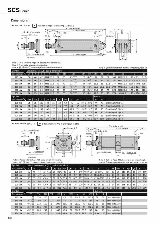
(File name: Page 442 or Ending 116 to 117)
(File name: Page 442 or Ending 116 to 117)
32
36
40
50
50
63
CB
25
28
32
40
40
50
MR
64
72
80
100
100
126
UB
Clevis bracket (CB) basic dimensions
125 dia.
140 dia.
160 dia.
180 dia.
200 dia.
250 dia.
Symbol
Bore size (mm)
125 dia.
140 dia.
160 dia.
180 dia.
200 dia.
250 dia.
BellowsSymbol
Bore size (mm)
• Clevis bracket (CB)
50
50
56
63
72
88
A
46
46
55
60
70
85
B
M14 X 1.5
M14 X 1.5
M16 X 1.5
M18 X 1.5
M20 X 1.5
M24 X 1.5
D
47
47
53
60
69
84
C
35
40
40
55
55
65
CC CD
20
22
24
25
30
35
CF EE
32
36
38.5
39.5
44.5
49.5
GA
29
36
36
38.5
45
50
GB
57
57
62.5
68.5
75
93
J
140
157
177
200
220
274
K
M30 X 1.5
M30 X 1.5
M36 X 1.5
M40 X 1.5
M45 X 1.5
M56 X 2
KK
83 to 91
91.5 to 99.5
101.5 to 109.5
113 to 121
123 to 131
150 to 158
L
91.5
102.5
105.5
109.5
122.5
140.5
LL
35
35
40
45
50
60
MM
110
124
142
160
175
216
N
14.5
16.5
16.5
16.5
17.5
20
QA
15
17
17
17
18
20.5
QB
18
18
21
24
27
34
T
46
46
48.5
53.5
60.5
64.5
V
65
67
71
78
88
94
WF
294.5
322.5
339.5
380.5
412.5
482.5
XC
219.5
244.5
251.5
277.5
300.5
344.5
XD
74
74
82
91
102
120
b
75
75
80
90
95
120
d
(Stroke length/4.55)+11
(Stroke length/4.55) + 9
(Stroke length/5.15) + 9
(Stroke length/5.15) + 9
(Stroke length/5.30) + 9
(Stroke length/6.40) + 9
25
28
32
40
40
50
+0.084 0+0.084 0+0.100 0+0.100 0+0.100 0+0.100 0
Rc /
Rc /
Rc /
Rc /
Rc /
Rc1
1
3
3
3
3
2
4
4
4
4
Note 1: Please refer to Page 405 about switch dimensions.Note 2: A pin and a snap ring are attached.Note 3: R , S and T show the positions of cushion needle. Note 4: dimensions below decimal point are rounded up.
Note 1: Please refer to Page 405 about switch dimensions.Note 2: R , S and T show the positions of cushion needle.
• Center trunnion type (TC)
50
55
60
65
70
80
CE
18
18
20
23
24
28
M
150
154
190
210
242
300
TC
170
190
212
236
265
335
TM
150
170
190
210
242
300
TN
2
2
2
2
2
2
TR
234
262
292
326
355
447
UM
224.5
237.5
252.5
273.5
306.5
350.5
X
64
69.5
73
78
85.5
98.5
XL
110.5
118
123.5
132.5
149
164
XV
Center trunnion type (TC) basic dimensions
125 dia.
140 dia.
160 dia.
180 dia.
200 dia.
250 dia.
Symbol
Bore size (mm)
125 dia.
140 dia.
160 dia.
180 dia.
200 dia.
250 dia.
BellowsSymbol
Bore size (mm)
Dimensions
50
50
56
63
72
88
A
46
46
55
60
70
80
B
M14 X 1.5
M14 X 1.5
M16 X 1.5
M18 X 1.5
M20 X 1.5
M24 X 1.5
D
47
47
53
60
69
84
C EE
32
36
38.5
39.5
44.5
49.5
GA
29
36
36
38.5
45
50
GB
57
57
62.5
68.5
75
93
J
140
157
177
200
220
274
K
M30 X 1.5
M30 X 1.5
M36 X 1.5
M40 X 1.5
M45 X 1.5
M56 X 2
KK
83 to 91
91.5 to 99.5
101.5 to 109.5
113 to 121
123 to 131
150 to 158
L
91.5
102.5
105.5
109.5
122.5
140.5
LL
35
35
40
45
50
60
MM
110
124
142
160
175
216
N
14.5
16.5
16.5
16.5
17.5
20
QA
15
17
17
17
18
20.5
QB
18
18
21
24
27
34
T
Rc /
Rc /
Rc /
Rc /
Rc /
Rc1
1
3
3
3
3
2
4
4
4
4
Note 3: Refer to Page 400 about minimum stroke length.Note 4: dimensions below decimal point are rounded up.
46
46
48.5
53.5
60.5
64.5
V
65
67
71
78
88
94
WF
74
74
82
91
102
120
b
75
75
80
90
95
120
d
(Stroke length/4.55)+11
(Stroke length/4.55) + 9
(Stroke length/5.15) + 9
(Stroke length/5.15) + 9
(Stroke length/5.30) + 9
(Stroke length/6.40) + 9
TD
32
36
40
45
45
56
-0.050-0.089-0.050-0.089-0.050-0.089-0.050-0.089-0.050-0.089-0.060-0.106
SCS Series
d di
a.
XC + + stroke length
<Bellows>
XD + + stroke length
WF +A
bMM dia.
J di
a.R MR
CDH10 dia.
8-D2-EE
KK
A WF
T
24 24
C GA
L
VLL + stroke length
XC + stroke length
XD + stroke length
KN
KN
CB + 0.4+ 0.1
-0.1-0.4UB
QA
GBCF
QB
CC
T
S
R
d di
a.
X + + stroke length
<Bellows>
WF +A
bMM dia.
J di
a.
R TR
8-D
2-EE
KK
A WF
T
24 24
C GA
L
VLL + stroke length
XV +
(X + stroke length)
K
N
K N
TCTM
TN
TDe8
dia
.
CE
QAGB
QB
(M)
T
S
R
UM
Stroke length2
XV + + Stroke length2 (XL + )Stroke length
2
409
Standard type
Larg
e bo
re size cylind
er
SCP * 2
CMK2
CMA2
SCM
SCA2
SCS
CKV2
CAT
MDC2
MVC
SMD2
SSD
FC *
JSB3
UCAC
LCS
LCY
STR2
UCA2
STK
USSD
USC
MFC
GLC
SHC
CAC3
HCM
HCA
MRL2
SRL2
SRG
SRM
SRT
SRB2
CAV2/COV * 2
MSD/MSDG
ULKP/ULKJSK2/JSM2
STS/STL
SSD (large)
JSC3 (medium)JSC3 (large)
(File name: Page 442 or Ending 116 to 117)
79
85.5
90
95.5
104
118
XK
Head side trunnion type (TB) basic dimensions
125 dia.
140 dia.
160 dia.
180 dia.
200 dia.
250 dia.
Symbol
Bore size (mm)
125 dia.
140 dia.
160 dia.
180 dia.
200 dia.
250 dia.
BellowsSymbol
Bore size (mm)
Dimensions
50
55
60
65
70
80
CE
18
18
20
23
24
28
M
95.5
102
106.5
115
130.5
144.5
TB
50
50
56
63
72
88
A
46
46
55
60
70
85
B
M14 X 1.5
M14 X 1.5
M16 X 1.5
M18 X 1.5
M20 X 1.5
M24 X 1.5
D
47
47
53
60
69
84
C EE
32
36
38.5
39.5
44.5
49.5
GA
29
36
36
38.5
45
50
GB
57
57
62.5
68.5
75
93
J
140
157
177
200
220
274
K
M30 X 1.5
M30 X 1.5
M36 X 1.5
M40 X 1.5
M45 X 1.5
M56 X 2
KK
83 to 91
91.5 to 99.5
101.5 to 109.5
113 to 121
123 to 131
150 to 158
L
91.5
102.5
105.5
109.5
122.5
140.5
LL
35
35
40
45
50
60
MM
110
124
142
160
175
216
N
14.5
16.5
16.5
16.5
17.5
20
QA
15
17
17
17
18
20.5
QB
18
18
21
24
27
34
T
Rc /
Rc /
Rc /
Rc /
Rc /
Rc1
1
3
3
3
3
2
4
4
4
4
74
74
82
91
102
120
b
75
75
80
90
95
120
d
(Stroke length/4.55)+11
(Stroke length/4.55) + 9
(Stroke length/5.15) + 9
(Stroke length/5.15) + 9
(Stroke length/5.30) + 9
(Stroke length/6.40) + 9
170
190
212
236
265
335
TM
150
170
190
210
242
300
TN
2
2
2
2
2
2
TR
234
262
292
326
355
447
UM
224.5
237.5
252.5
273.5
306.5
305.5
X
46
46
48.5
53.5
60.5
64.5
V
65
67
71
78
88
94
WFTD
32
36
40
45
45
56
-0.050-0.089-0.050-0.089-0.050-0.089-0.050-0.089-0.050-0.089-0.060-0.106
150
154
190
210
242
300
TC
• Head side trunnion type (TB)
Note 1: Please refer to Page 405 about switch dimensions.Note 2: R , S and T show the positions of cushion needle.
Note 3: Refer to Page 400 about minimum stroke length.Note 4: dimensions below decimal point are rounded up.Note 5: The position at head side stroke end cannot be detected.
(File name: Page 442 or Ending 116 to 117)• Rod side trunnion type (TA)
125.5
134
140.5
150
167.5
183.5
XG
48.5
53
55.5
60
66.5
98.5
XH
Rod side trunnion type (TA) basic dimensions
125 dia.
140 dia.
160 dia.
180 dia.
200 dia.
250 dia.
Symbol
Bore size (mm)
125 dia.
140 dia.
160 dia.
180 dia.
200 dia.
250 dia.
BellowsSymbol
Bore size (mm)
74
74
82
91
102
120
b
75
75
80
90
95
120
d
(Stroke length/4.55)+11
(Stroke length/4.55) + 9
(Stroke length/5.15) + 9
(Stroke length/5.15) + 9
(Stroke length/5.30) + 9
(Stroke length/6.40) + 9
170
190
212
236
265
335
TM
150
170
190
210
242
300
TN
2
2
2
2
2
2
TR
234
262
292
326
355
447
UM
224
237
252
273
306
350
X
46
46
48.5
53.5
60.5
64.5
V
65
67
71
78
88
94
WFTD
32
36
40
45
45
56
-0.050-0.089-0.050-0.089-0.050-0.089-0.050-0.089-0.050-0.089-0.060-0.106
50
55
60
65
70
80
CE
18
18
20
23
24
28
M
150
154
190
210
242
300
TC
50
50
56
63
72
88
A
46
46
55
60
70
80
B
M14 X 1.5
M14 X 1.5
M16 X 1.5
M18 X 1.5
M20 X 1.5
M24 X 1.5
D
47
47
53
60
69
84
C EE
32
36
38.5
39.5
44.5
49.5
GA
29
36
36
38.5
45
50
GB
57
57
62.5
68.5
75
93
J
140
157
177
200
220
274
K
M30 X 1.5
M30 X 1.5
M36 X 1.5
M40 X 1.5
M45 X 1.5
M56 X 2
KK
83 to 91
91.5 to 99.5
101.5 to 109.5
113 to 121
123 to 131
150 to 158
L
91.5
102.5
105.5
109.5
122.5
140.5
LL
35
35
40
45
50
60
MM
110
124
142
160
175
216
N
14.5
16.5
16.5
16.5
17.5
20
QA
15
17
17
17
18
20.5
QB
18
18
21
24
27
34
T
Rc /
Rc /
Rc /
Rc /
Rc /
Rc1
1
3
3
3
3
2
4
4
4
4
Note 3: Refer to Page 400 about minimum stroke length.Note 4: dimensions below decimal point are rounded up.Note 5: The position at rod side stroke end cannot be detected.
Note 1: Please refer to Page 405 about switch dimensions.Note 2: R , S and T show the positions of cushion needle.
SCS Series
Double acting/single rod/lubrication type/pre-lubricated typed
dia.
X + + stroke length
<Bellows>
TB + + stroke length
WF +A
b
MM dia.
J di
a.
R TR
8-D2-EE
KK
A WF
T
24 24
C GA
L
V
LL + stroke length
(X + stroke length)
TB + stroke length
K
N
KN
TCTM
TN
(XK)
CE
QA
GB
QB
(M)
T
S
R
UM
TD
e8 d
ia.
d di
a.
X + + stroke length
<Bellows>
WF +A
b
XG +
MM dia.
J di
a.
R TR
8-D
2-EE
KK
A WF
T
24 24
C GA
L
V
LL + stroke length(X + stroke length)
(XH + stroke length)
K
N
K N
TCTM
TN
TD
e8 d
ia.
XGCE
QA
GB
QB
(M)
T
S
R
UM
410
JIS symbol
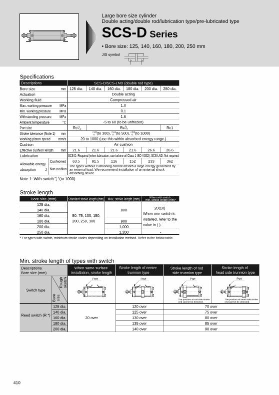
Large bore size cylinderDouble acting/double rod/lubrication type/pre-lubricated type
SCS-D Series• Bore size: 125, 140, 160, 180, 200, 250 mm
Descriptions SCS-D/SCS-LND (double rod type)
Bore size mm
Actuation
Working fluid
Max. working pressure MPa
Min. working pressure MPa
Withstanding pressure MPa
Ambient temperature °CPort size
Stroke tolerance (Note 1) mm
Working piston speed mm/s
Cushion
Effective cushion length mm
Lubrication
Cushioned
Non cushion
250 dia.
Rc1
26.6
362
200 dia.
26.6
233
180 dia.
21.6
152
160 dia.
21.6
116
Double acting
Compressed air
1.0
0.1
1.6
-5 to 60 (to be unfrozen)
Rc /
(to 300), (to 500), (to 1000)
20 to 1000 (use this within absorbed energy range.)
Air cushion
SCS-D: Required (when lubrication, use turbine oil Class 1 ISO VG32), SCS-LND: Not required
140 dia.
21.6
91.5
125 dia.
Rc /
21.6
63.5
+1.00
+1.40
+2.00
12
34
Note 1: With switch (to 1000)+2.0 0
Specifications
* For types with switch, minimum stroke varies depending on installation method. Refer to the below table.
Stroke lengthBore size (mm)
125 dia.
140 dia.
160 dia.
180 dia.
200 dia.
250 dia.
Standard stroke length (mm) Max. stroke length (mm)
800
900
1,000
1,200
50, 75, 100, 150,
200, 250, 300
When with switch, min. stroke length (mm)*
20(10)
When one switch is
installed, refer to the
value in ( ).
-
The types without cushioning cannot absorb a large energy generated by an external load. We recommend installation of an external shock absorbing device.
Min. stroke length of types with switch
20 over
125 dia.
140 dia.
160 dia.
180 dia.
200 dia.
120 over
125 over
130 over
135 over
140 over
The position at rod side stroke end cannot be detected.
The position at head side stroke end cannot be detected.
When same surface installation, stroke length
DescriptionsBore size (mm)
Switch type
Rou
ghsk
etch
Bor
esi
ze
Reed switch (R *)
Stroke length of center trunnion type
Stroke length of rod side trunnion type
Stroke length of head side trunnion type
70 over
75 over
80 over
85 over
90 over
Port PortPort Port
Allowable energy
absorption J
411
Standard type
Larg
e bo
re size cylind
er
SCP * 2
CMK2
CMA2
SCM
SCA2
SCS
CKV2
CAT
MDC2
MVC
SMD2
SSD
FC *
JSB3
UCAC
LCS
LCY
STR2
UCA2
STK
USSD
USC
MFC
GLC
SHC
CAC3
HCM
HCA
MRL2
SRL2
SRG
SRM
SRT
SRB2
CAV2/COV * 2
MSD/MSDG
ULKP/ULKJSK2/JSM2
STS/STL
SSD (large)
JSC3 (medium)JSC3 (large)
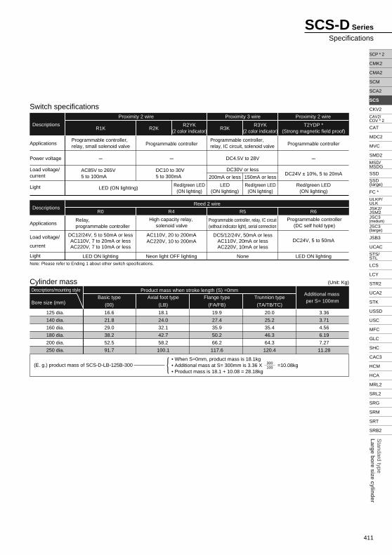
(E. g.) product mass of SCS-D-LB-125B-300• When S=0mm, product mass is 18.1kg• Additional mass at S= 300mm is 3.36 X =10.08kg• Product mass is 18.1 + 10.08 = 28.18kg
300100
Cylinder mass
Axial foot type
(LB)
125 dia.
140 dia.
160 dia.
180 dia.
200 dia.
250 dia.
Additional mass per S= 100mmBore size (mm)
Descriptions/mounting style Product mass when stroke length (S) =0mm
18.1
24.0
32.1
42.7
58.2
100.1
Basic type
(00)
16.6
21.8
29.0
38.2
52.5
91.7
Flange type
(FA/FB)
19.9
27.4
35.9
50.2
66.2
117.6
Trunnion type
(TA/TB/TC)
20.0
25.2
35.4
46.3
64.3
120.4
3.36
3.71
4.56
6.19
7.27
11.28
(Unit: Kg)
Note: Please refer to Ending 1 about other switch specifications.
R1K
R0 R4 R5 R6
LED ON lighting Neon light OFF lighting None LED ON lighting
DC12/24V, 5 to 50mA or lessAC110V, 7 to 20mA or lessAC220V, 7 to 10mA or less
AC110V, 20 to 200mAAC220V, 10 to 200mA
DC5/12/24V, 50mA or lessAC110V, 20mA or lessAC220V, 10mA or less
DC24V, 5 to 50mA
High capacity relay, solenoid valve
Relay, programmable controller
Programmable controller, relay, IC circuit(without indicator light), serial connection
Programmable controller(DC self hold type)
Applications
Power voltage
Load voltage/current
Light
Applications
Load voltage/
current
Light
R2KR2YK
(2 color indicator)
Red/green LED(ON lighting)
R3KR3YK
(2 color indicator)
200mA or less 150mA or less
T2YDP *(Strong magnetic field proof)
LED (ON lighting)LED
(ON lighting)Red/green LED
(ON lighting)Red/green LED
(ON lighting)
AC85V to 265V5 to 100mA
DC10 to 30V5 to 300mA DC24V ± 10%, 5 to 20mA
Programmable controller, relay, small solenoid valve Programmable controller
Programmable controller, relay, IC circuit, solenoid valve Programmable controller
- - DC4.5V to 28V
DC30V or less
-
Switch specifications
Descriptions
Proximity 2 wire Proximity 2 wireProximity 3 wire
Reed 2 wireDescriptions
SCS-D Series
Specifications
412
SCS-D Series
A
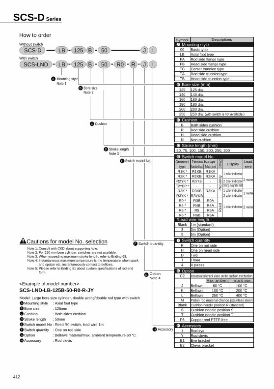
How to order
Without switch
With switch
Mounting styleNote 1
B Bore sizeNote 2
C Cushion
D Stroke lengthNote 3
E Switch model No.
G OptionNote 4
H Accessory
F Switch quantity
<Example of model number>SCS-LND-LB-125B-50-R0-R-JYModel: Large bore size cylinder, double acting/double rod type with switch
Mounting style : Axial foot type
Bore size : 125mm
Cushion : Both sides cushion
Stroke length : 50mm
Switch model No : Reed R0 switch, lead wire 1m
Switch quantity : One on rod side
Option : Bellows material/max. ambient temperature 60 °CAccessory : Rod clevis
A
B
C
D
E
F
G
H
Cautions for model No. selection
SCS-LND LB 125 JRB IR050
SCS-D LB 125 JB I50
Symbol Descriptions
00LBFAFBTCTATB
125140160180200250
BRHN
Blank35
RHDT4
C2
JKLM
BlankST
P6
IY
B1B2
Mounting styleA
Bore size (mm)B
CushionC
Stroke length (mm)D
Switch model No.E
*Lead wire length
OptionG
AccessoryH
Switch quantityF
Basic typeAxial foot typeRod side flange typeHead side flange typeCenter trunnion typeRod side trunnion typeHead side trunnion type
125 dia.140 dia.160 dia.180 dia.200 dia.250 dia. (with switch is not available.)
Both sides cushionRod side cushionHead side cushionNon cushion
1m (standard)3m (Option)5m (Option)
One on rod sideOne on head sideTwoThree4 pieces
Incorporated check valve on the cushion mechanism
BellowsBellowsBellowsPiston rod material change (stainless steel)Cushion needle position R (standard)Cushion needle position SCushion needle position TCopper and PTFE free
Rod eyeRod clevisEye bracketClevis bracket
50, 75, 100, 150, 200, 250, 300
Leadwire
2 wire
3 wire
2 wire
Cont
act
Pro
xim
ityR
eed
Terminal box typeDisplay
1 color indicator
2 color indicatorStrong magnetic field1 color indicator2 color indicator
1 color indicator
Standard typeR1KBR2KBR2YKB
-R3KB
R3YKBR0BR4BR5
R6B
Splash-proofR1KAR2KA
--
R3KA-
R0AR4AR5AR6A
Grommettype
R1K *R2K *
R2YK *T2YDP *R3K *
R3YK *R0 *R4 *R5 *R6 *
Max. ambient60 °C100 °C250 °C
Instant max.100 °C200 °C400 °C
Note 1: Consult with CKD about supporting hole.Note 2: For 250 mm bore cylinder, switches are not available.Note 3: When exceeding maximum stroke length, refer to Ending 68.Note 4: Instantaneous maximum temperature is the temperature when spark
and spatter etc. instantaneously contact to bellows.Note 5: Please refer to Ending 81 about custom specifications of rod end
form.
413
Standard type
Larg
e bo
re size cylind
er
SCP * 2
CMK2
CMA2
SCM
SCA2
SCS
CKV2
CAT
MDC2
MVC
SMD2
SSD
FC *
JSB3
UCAC
LCS
LCY
STR2
UCA2
STK
USSD
USC
MFC
GLC
SHC
CAC3
HCM
HCA
MRL2
SRL2
SRG
SRM
SRT
SRB2
CAV2/COV * 2
MSD/MSDG
ULKP/ULKJSK2/JSM2
STS/STL
SSD (large)
JSC3 (medium)JSC3 (large)
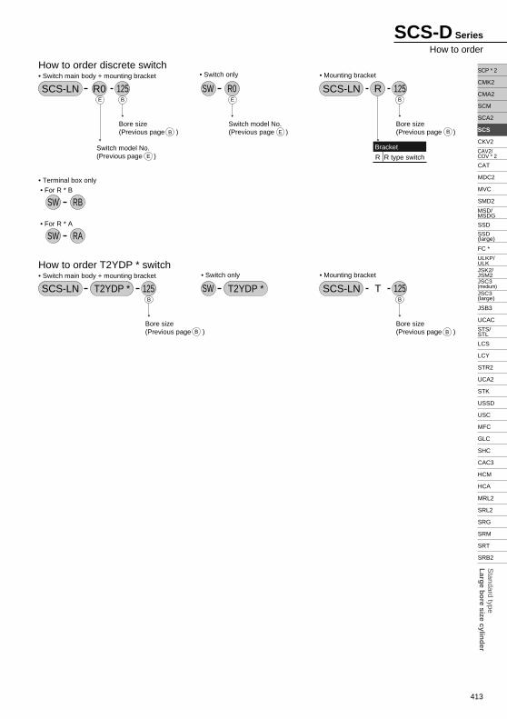
Switch model No.(Previous page )
How to order discrete switch• Switch main body + mounting bracket
SCS-LN R0 125B
B
E E
E
E
Bore size(Previous page )
B
BBore size(Previous page )
B
BBore size(Previous page )
Switch model No.(Previous page )
• Mounting bracket
SCS-LN 125RB
BBore size(Previous page )
Bracket
R R type switch
• Switch only
SW R0
How to order T2YDP * switch• Switch main body + mounting bracket
T2YDP * 125• Mounting bracket
SCS-LN 125T• Switch only
SWSCS-LN T2YDP *
• Terminal box only • For R * B
SW RB
• For R * A
SW RA
SCS-D Series
How to order
414
SCS-D Series
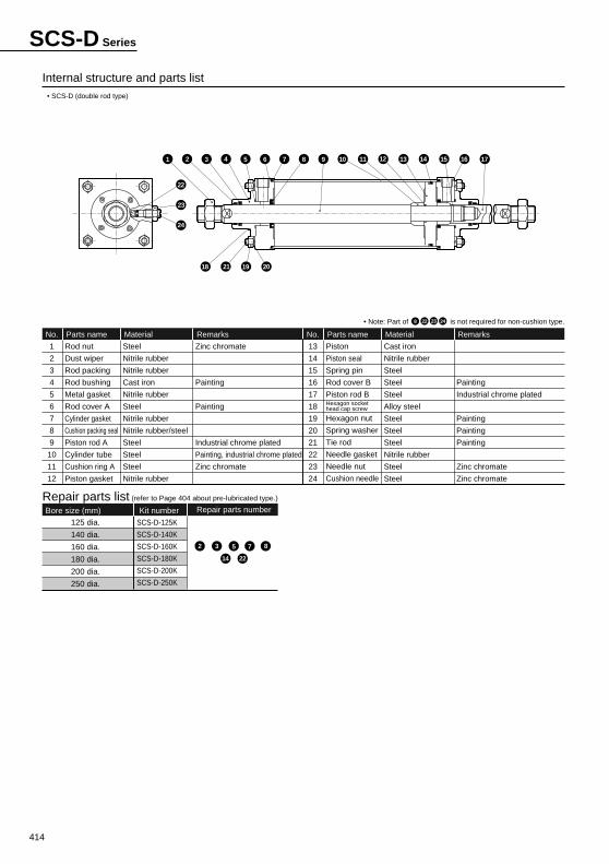
Internal structure and parts list
1
2
3
4
5
6
7
8
9
10
11
12
Rod nut
Dust wiper
Rod packing
Rod bushing
Metal gasket
Rod cover A
Cylinder gasket
Cushion packing seal
Piston rod A
Cylinder tube
Cushion ring A
Piston gasket
Parts name
Steel
Nitrile rubber
Nitrile rubber
Cast iron
Nitrile rubber
Steel
Nitrile rubber
Nitrile rubber/steel
Steel
Steel
Steel
Nitrile rubber
Material
Zinc chromate
Painting
Painting
Industrial chrome plated
Painting, industrial chrome plated
Zinc chromate
Remarks
Painting
Industrial chrome plated
Painting
Painting
Painting
Zinc chromate
Zinc chromate
No.
13
14
15
16
17
18
19
20
21
22
23
24
Piston
Piston seal
Spring pin
Rod cover B
Piston rod BHexagon socket head cap screw
Hexagon nut
Spring washer
Tie rod
Needle gasket
Needle nut
Cushion needle
Parts name
Cast iron
Nitrile rubber
Steel
Steel
Steel
Alloy steel
Steel
Steel
Steel
Nitrile rubber
Steel
Steel
Material RemarksNo.
Repair parts list (refer to Page 404 about pre-lubricated type.)
• SCS-D (double rod type)
• Note: Part of is not required for non-cushion type.
Bore size (mm) Kit number Repair parts number
125 dia.
140 dia.
160 dia.
180 dia.
200 dia.
250 dia.
SCS-D-125K
SCS-D-140K
SCS-D-160K
SCS-D-180K
SCS-D-200K
SCS-D-250K
2 3 5 7 8
14 22
22 24238
6 981 102
22
23
24
74 53 11 12 13 14 15 16 17
18 21 19 20
415
Standard type
Larg
e bo
re size cylind
er
SCP * 2
CMK2
CMA2
SCM
SCA2
SCS
CKV2
CAT
MDC2
MVC
SMD2
SSD
FC *
JSB3
UCAC
LCS
LCY
STR2
UCA2
STK
USSD
USC
MFC
GLC
SHC
CAC3
HCM
HCA
MRL2
SRL2
SRG
SRM
SRT
SRB2
CAV2/COV * 2
MSD/MSDG
ULKP/ULKJSK2/JSM2
STS/STL
SSD (large)
JSC3 (medium)JSC3 (large)
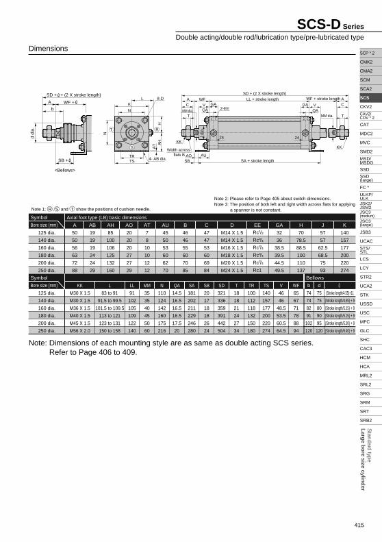
Dimensions
50
50
56
63
72
88
A
19
19
19
24
24
29
AB
85
100
106
125
132
160
AH
20
20
20
27
27
29
AO
7
8
10
10
12
12
AT
45
50
53
60
62
70
AU
46
46
55
60
70
85
B
M14 X 1.5
M14 X 1.5
M16 X 1.5
M18 X 1.5
M20 X 1.5
M24 X 1.5
D
47
47
53
60
69
84
C EE
32
36
38.5
39.5
44.5
49.5
GA
70
78.5
88.5
100
110
137
H
57
57
62.5
68.5
75
93
J
140
157
177
200
220
274
K
M30 X 1.5
M30 X 1.5
M36 X 1.5
M40 X 1.5
M45 X 1.5
M56 X 2.0
KK
83 to 91
91.5 to 99.5
101.5 to 109.5
113 to 121
123 to 131
150 to 158
L
91
102
105
109
122
140
LL
35
35
40
45
50
60
MM
110
124
142
160
175
216
N
14.5
16.5
16.5
16.5
17.5
20
QA
181
202
211
229
246
280
SA
20
17
18
18
26
24
SB
321
336
359
391
442
504
SD
18
18
21
24
27
34
T
100
112
118
132
150
180
TR
140
157
177
200
220
274
TS
46
46
48.5
53.5
60.5
64.5
V
65
67
71
78
88
94
WF
Axial foot type (LB) basic dimensions
125 dia.
140 dia.
160 dia.
180 dia.
200 dia.
250 dia.
Symbol
Bore size (mm)
125 dia.
140 dia.
160 dia.
180 dia.
200 dia.
250 dia.
Symbol
Bore size (mm)
Note 2: Please refer to Page 405 about switch dimensions.Note 3: The position of both left and right width across flats for applying
a spanner is not constant.
Rc /
Rc /
Rc /
Rc /
Rc /
Rc1
1
3
3
3
3
2
4
4
4
4
Note: Dimensions of each mounting style are as same as double acting SCS series. Refer to Page 406 to 409.
74
74
82
91
102
120
b
75
75
80
90
95
120
d
(Stroke length/4.55)+11
(Stroke length/4.55) + 9
(Stroke length/5.15) + 9
(Stroke length/5.15) + 9
(Stroke length/5.30) + 9
(Stroke length/6.40) + 9
Bellows
Note 1: R , S and T show the positions of cushion needle.
SCS-D Series
Double acting/double rod/lubrication type/pre-lubricated type
MM dia.
J di
a.
4- AB dia.
8-D
2-EE
KK
Width across flats B
KK
A WF
T MM dia. T
24 24
C GAL
VLL + stroke length WF + stroke length
SD + (2 X stroke length)
SA + stroke length
K
N
TRTS
HA
HA
T
SBAO AU
QAGA
QAV C
AN
T
S
R
SD + + (2 X stroke length)
d di
a.
WF +A
b
SB +
<Bellows>
416
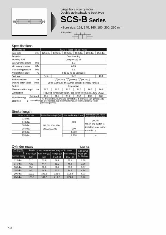
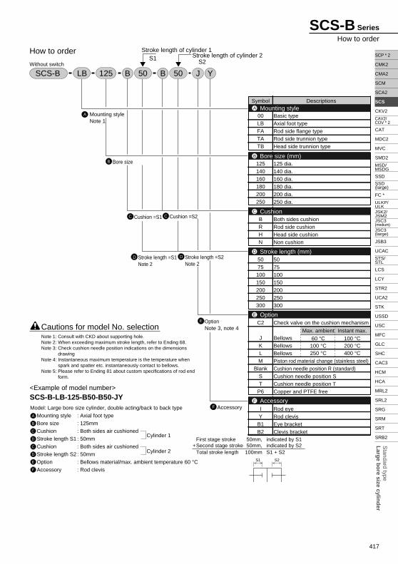
Large bore size cylinderDouble acting/back to back type
SCS-B Series• Bore size: 125, 140, 160, 180, 200, 250 mm
SpecificationsDescriptions SCS-B (back to back type)
Bore size mm
Actuation
Working fluid
Max. working pressure MPa
Min. working pressure MPa
Withstanding pressure MPa
Ambient temperature °CPort size
Stroke tolerance mm
Working piston speed mm/s
Cushion
Effective cushion length mm
Lubrication
Cushioned
Non cushion
250 dia.
Rc1
26.6
362
200 dia.
26.6
233
180 dia.
21.6
152
160 dia.
21.6
116
Double acting
Compressed air
1.0
0.05
1.6
-5 to 60 (to be unfrozen)
Rc /
(to 300), (to 500), (to 1000)
20 to 1000 (use this within absorbed energy range.)
Air cushion
Required (when lubrication, use turbine oil Class 1 ISO VG32)
140 dia.
21.6
91.5
125 dia.
Rc /
21.6
63.5
+1.00
+1.40
12
34
Stroke lengthBore size (mm)
125 dia.
140 dia.
160 dia.
180 dia.
200 dia.
250 dia.
Standard stroke length (mm) Max. stroke length (mm)
800
900
1,000
1,200
50, 75, 100, 150,
200, 250, 300
When types with switch,min. stroke length (mm)
20(10)
When one switch is
installed, refer to the
value in ( ).
-
+1.40
The types without cushioning cannot absorb a large energy generated by an external load. We recommend installation of an external shock absorbing device.
Cylinder mass
Axial foot type
(LB)
125 dia.
140 dia.
160 dia.
180 dia.
200 dia.
250 dia.
Additionalmass per S= 100mmBore size (mm)
Descriptions/mounting style Product mass when stroke length (S) =0mm
32.6
44.4
58.8
78.6
106.6
184.2
Basic type
(00)
31.1
42.2
55.7
74.1
100.9
175.8
Flange type
(FA/FB)
36.2
51.2
66.4
93.6
122.6
219.2
Trunnion type
(TA/TB)
36.4
46.8
65.4
85.8
118.8
224.8
2.60
2.96
3.57
4.94
5.73
9.06
(Unit: Kg)
Allowable energy
absorption J
JIS symbol
417
Standard type
Larg
e bo
re size cylind
er
SCP * 2
CMK2
CMA2
SCM
SCA2
SCS
CKV2
CAT
MDC2
MVC
SMD2
SSD
FC *
JSB3
UCAC
LCS
LCY
STR2
UCA2
STK
USSD
USC
MFC
GLC
SHC
CAC3
HCM
HCA
MRL2
SRL2
SRG
SRM
SRT
SRB2
CAV2/COV * 2
MSD/MSDG
ULKP/ULKJSK2/JSM2
STS/STL
SSD (large)
JSC3 (medium)JSC3 (large)
SCS-B Series
How to order
A
B
How to order
C C Cushion =S2
D Stroke length =S1Note 2
D Stroke length =S2Note 2
E OptionNote 3, note 4
F Accessory
Symbol Descriptions
00LBFATATB
125140160180200250
BRHN
5075
100150200250300
C2
JKLM
BlankST
P6
IY
B1B2
Basic typeAxial foot typeRod side flange typeRod side trunnion typeHead side trunnion type
125 dia.140 dia.160 dia.180 dia.200 dia.250 dia.
Both sides cushionRod side cushionHead side cushionNon cushion
5075100150200250300
Check valve on the cushion mechanism
BellowsBellowsBellowsPiston rod material change (stainless steel)Cushion needle position R (standard)Cushion needle position SCushion needle position TCopper and PTFE free
Rod eyeRod clevisEye bracketClevis bracket
Mounting styleA
Bore size (mm)B
CushionC
Option
Stroke length (mm)
E
D
AccessoryF
JB YSCS-B LB 50 B 50125
<Example of model number>SCS-B-LB-125-B50-B50-JYModel: Large bore size cylinder, double acting/back to back type
Mounting style : Axial foot type
Bore size : 125mm
Cushion : Both sides air cushioned
Stroke length S1 : 50mm
Cushion : Both sides air cushioned
Stroke length S2 : 50mm
Option : Bellows material/max. ambient temperature 60 °CAccessory : Rod clevis
A
B
C
D
C
D
E
F
Stroke length of cylinder 1S1 S2
Stroke length of cylinder 2
First stage stroke 50mm, indicated by S1+Second stage stroke 50mm, indicated by S2
Total stroke length 100mm S1 + S2Cylinder 2
Cylinder 1
Without switch
Cushion =S1
Bore size
Mounting styleNote 1
S1 S2
Cautions for model No. selection Max. ambient
60 °C100 °C250 °C
Instant max.
100 °C200 °C400 °C
Note 1: Consult with CKD about supporting hole.Note 2: When exceeding maximum stroke length, refer to Ending 68.Note 3: Check cushion needle position indications on the dimensions
drawingNote 4: Instantaneous maximum temperature is the temperature when
spark and spatter etc. instantaneously contact to bellows.Note 5: Please refer to Ending 81 about custom specifications of rod end
form.
418
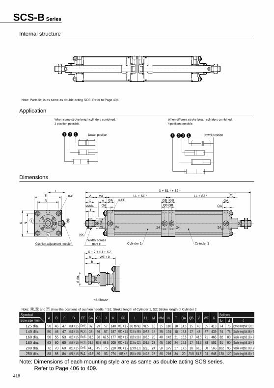
Internal structure
Application
Dimensions
50
50
56
63
72
88
A
M14 X 1.5
M14 X 1.5
M16 X 1.5
M18 X 1.5
M20 X 1.5
M24 X 1.5
D
47
47
53
60
69
84
C
46
46
55
60
70
85
B EE
32
36
38.5
39.5
44.5
49.5
GA
29
36
36
38.5
45
50
GB
57
57
62.5
68.5
75
93
J
140
157
177
200
220
274
K
M30 X 1.5
M30 X 1.5
M36 X 1.5
M40 X 1.5
M45 X 1.5
M56 X 2
KK
83 to 91
91.5 to 99.5
101.5 to 109.5
113 to 121
123 to 131
150 to 158
L
91.5
102.5
105.5
109.5
122.5
140.5
LL
18
18
20
23
24
28
M
35
35
40
45
50
60
MM
110
124
142
160
175
216
N
18
18
21
24
27
34
T
14.5
16.5
16.5
16.5
17.5
20
QA
15
17
17
17
18
20.5
QB
46
46
48.5
53.5
60.5
64.5
V
65
67
71
78
88
94
WF
413
439
465
501
565
645
X
125 dia.
140 dia.
160 dia.
180 dia.
200 dia.
250 dia.
Symbol
Bore size (mm)
Note: Parts list is as same as double acting SCS. Refer to Page 404.
When same stroke length cylinders combined.3 position possible.
When different stroke length cylinders combined.4 position possible.
Rc /
Rc /
Rc /
Rc /
Rc /
Rc1
1
3
3
3
3
2
4
4
4
4
74
74
82
91
102
120
b
75
75
80
90
95
120
d
(Stroke length/4.55)+11
(Stroke length/4.55) + 9
(Stroke length/5.15) + 9
(Stroke length/5.15) + 9
(Stroke length/5.30) + 9
(Stroke length/6.40) + 9
Bellows
Note: Dimensions of each mounting style are as same as double acting SCS series. Refer to Page 406 to 409.
Note: R , S and T show the positions of cushion needle. * S1: Stroke length of Cylinder 1, S2: Stroke length of Cylinder 2
SCS-B Series
MM dia.
J di
a.
8-D4-EE
KK
Width acrossflats B
A WF
T
24 2424 24
C GA
L
V
LL + S1 * LL + S2 *
X + S1 * + S2 *
Cylinder 1Cushion adjustment needle Cylinder 2
K
N
K N
QA
GA
QAQB QB
(M)
GBGB
T
S
R
Dowel position3 2 1 Dowel position34 2 1
d di
a.
X + + S1 + S2
WF +A
b
<Bellows>
420
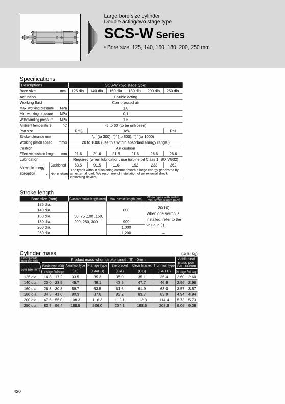
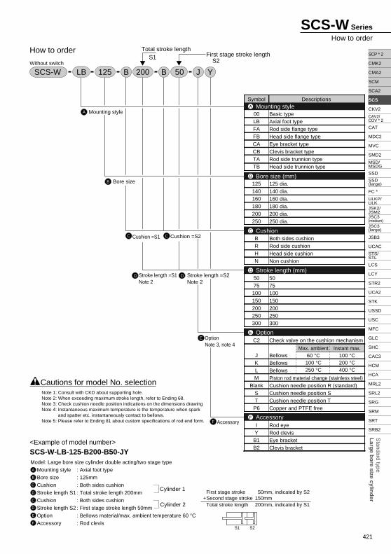
Large bore size cylinderDouble acting/two stage type
SCS-W Series• Bore size: 125, 140, 160, 180, 200, 250 mm
SpecificationsDescriptions SCS-W (two stage type)
Bore size mm
Actuation
Working fluid
Max. working pressure MPa
Min. working pressure MPa
Withstanding pressure MPa
Ambient temperature °CPort size
Stroke tolerance mm
Working piston speed mm/s
Cushion
Effective cushion length mm
Lubrication
Cushioned
Non cushion
250 dia.
Rc1
26.6
362
200 dia.
26.6
233
180 dia.
21.6
152
160 dia.
21.6
116
Double acting
Compressed air
1.0
0.1
1.6
-5 to 60 (to be unfrozen)
Rc /
(to 300), (to 500), (to 1000)
20 to 1000 (use this within absorbed energy range.)
Air cushion
Required (when lubrication, use turbine oil Class 1 ISO VG32)
140 dia.
21.6
91.5
125 dia.
Rc /
21.6
63.5
+1.00
+1.40
+1.40
12
34
Stroke lengthBore size (mm)
125 dia.
140 dia.
160 dia.
180 dia.
200 dia.
250 dia.
Standard stroke length (mm) Max. stroke length (mm)
800
900
1,000
1,200
50, 75 ,100 ,150,
200, 250, 300
When types with switch, min. stroke length (mm)
20(10)
When one switch is
installed, refer to the
value in ( ).
-
The types without cushioning cannot absorb a large energy generated by an external load. We recommend installation of an external shock absorbing device.
Cylinder mass
Axial foot type
(LB)
125 dia.
140 dia.
160 dia.
180 dia.
200 dia.
250 dia.
Additionalmass per S= 100mm
Bore size (mm)
Descriptions/mounting style Product mass when stroke length (S) =0mm
33.5
45.7
59.7
80.3
108.3
188.5
Basic type (00)
14.8
20.0
26.3
34.8
47.6
83.7
17.2
23.5
30.3
41.0
55.0
96.4
1st stage 2nd stage
Flange type
(FA/FB)
35.3
49.1
63.5
87.8
116.3
206.0
Eye bracket
(CA)
35.0
47.5
61.6
83.2
112.1
204.1
Clevis bracket
(CB)
35.1
47.7
61.9
83.7
112.3
198.6
Trunnion type
(TA/TB)
35.4
46.9
63.0
83.9
114.4
208.8
2.60
2.96
3.57
4.94
5.73
9.06
2.60
2.96
3.57
4.94
5.73
9.06
2nd stage1st stage
(Unit: Kg)
Allowable energy
absorption J
421
Standard type
Larg
e bo
re size cylind
er
SCP * 2
CMK2
CMA2
SCM
SCA2
SCS
CKV2
CAT
MDC2
MVC
SMD2
SSD
FC *
JSB3
UCAC
LCS
LCY
STR2
UCA2
STK
USSD
USC
MFC
GLC
SHC
CAC3
HCM
HCA
MRL2
SRL2
SRG
SRM
SRT
SRB2
CAV2/COV * 2
MSD/MSDG
ULKP/ULKJSK2/JSM2
STS/STL
SSD (large)
JSC3 (medium)JSC3 (large)
SCS-W Series
How to order
A
B
How to order
CC Cushion =S2
D Stroke length =S1Note 2
D Stroke length =S2Note 2
E OptionNote 3, note 4
F Accessory
Symbol Descriptions
00LBFAFBCACBTATB
125140160180200250
BRHN
5075
100150200250300
C2
JKLM
BlankST
P6
IY
B1B2
Basic typeAxial foot typeRod side flange typeHead side flange typeEye bracket typeClevis bracket typeRod side trunnion typeHead side trunnion type
125 dia.140 dia.160 dia.180 dia.200 dia.250 dia.
Both sides cushionRod side cushionHead side cushionNon cushion
5075100150200250300
Check valve on the cushion mechanism
BellowsBellowsBellowsPiston rod material change (stainless steel)Cushion needle position R (standard)Cushion needle position SCushion needle position TCopper and PTFE free
Rod eyeRod clevisEye bracketClevis bracket
Mounting styleA
Bore size (mm)B
CushionC
Option
Stroke length (mm)
E
D
AccessoryF
SCS-W
<Example of model number>
SCS-W-LB-125-B200-B50-JYModel: Large bore size cylinder double acting/two stage type
Mounting style : Axial foot type
Bore size : 125mm
Cushion : Both sides cushion
Stroke length S1 : Total stroke length 200mm
Cushion : Both sides cushion
Stroke length S2 : First stage stroke length 50mm
Option : Bellows material/max. ambient temperature 60 °CAccessory : Rod clevis
A
B
C
D
C
D
E
F
Cautions for model No. selection
Total stroke lengthS1 S2
First stage stroke length
First stage stroke 50mm, indicated by S2+Second stage stroke 150mm
Total stroke length 200mm, indicated by S1Cylinder 2
Cylinder 1
Without switch
S1 S2
BLB 125 J YB200 50
Cushion =S1
Bore size
Mounting style
Max. ambient60 °C100 °C250 °C
Instant max.100 °C200 °C400 °C
Note 1: Consult with CKD about supporting hole.Note 2: When exceeding maximum stroke length, refer to Ending 68.Note 3: Check cushion needle position indications on the dimensions drawingNote 4: Instantaneous maximum temperature is the temperature when spark
and spatter etc. instantaneously contact to bellows.Note 5: Please refer to Ending 81 about custom specifications of rod end form.
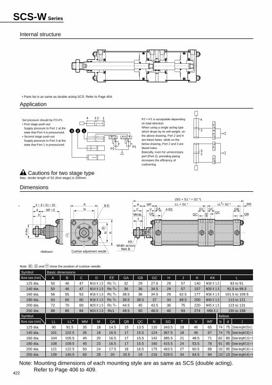
422
Internal structure
Application
Basic dimensions
125 dia.
140 dia.
160 dia.
180 dia.
200 dia.
250 dia.
Symbol
Bore size (mm)
125 dia.
140 dia.
160 dia.
180 dia.
200 dia.
250 dia.
Symbol
Bore size (mm)
Dimensions
Cautions for two stage type
50
50
56
63
72
88
A
46
46
55
60
70
85
B
47
47
53
60
69
84
C
M14 X 1.5
M14 X 1.5
M16 X 1.5
M18 X 1.5
M20 X 1.5
M24 X 1.5
D EE
32
36
38.5
39.5
44.5
49.5
GA
29
36
36
38.5
45
50
GB
27.6
34.5
34.5
37
43.5
48.5
GC
29
29
29
34
36
40
H
57
57
62.5
68.5
75
93
J
140
157
177
200
220
274
K
M30 X 1.5
M30 X 1.5
M36 X 1.5
M40 X 1.5
M45 X 1.5
M56 X 2
KK
83 to 91
91.5 to 99.5
101.5 to 109.5
113 to 121
123 to 131
150 to 158
L
90
101
104
108
121
139
LL
91.5
102.5
105.5
109.5
122.5
140.5
LL
35
35
40
45
50
60
MM
18
18
20
23
24
28
M
14.5
16.5
16.5
16.5
17.5
20
QA
15
17
17
17
18
20.5
QB
13.5
15.5
15.5
15.5
16.5
19
QC
110
124
142
160
175
216
N
343.5
367.5
385.5
415.5
463.5
529.5
SG
18
18
21
24
27
34
T
46
46
48.5
53.5
60.5
64.5
V
65
67
71
78
88
94
WF
Rc /
Rc /
Rc /
Rc /
Rc /
Rc1
1
3
3
3
3
2
4
4
4
4
Max. stroke length of S2 (first stage) is 200mm.
Note: Mounting dimensions of each mounting style are as same as SCS (double acting). Refer to Page 406 to 409.
• Parts list is as same as double acting SCS. Refer to Page 404.
P2 = P1 is acceptable depending on load direction.When using a single acting type which drops by its self weight, on the above drawing, Port 2 and 4 are bleed holes, while on the below drawing, Port 2 and 3 are bleed holes.Basically, even for unnecessary port (Port 2), providing piping increases the efficiency of cushioning.
74
74
82
91
102
120
b
75
75
80
90
95
120
d
(Stroke length/4.55)+11
(Stroke length/4.55) + 9
(Stroke length/5.15) + 9
(Stroke length/5.15) + 9
(Stroke length/5.30) + 9
(Stroke length/6.40) + 9
Bellows
Note: R , S and T show the position of cushion needle.
Set pressure should be P2>P1.• First stage push-out
Supply pressure to Port 1 at the state that Port 4 is pressurized.
• Second stage push-outSupply pressure to Port 3 at the state that Port 1 is pressurized.
SCS-W Series
MM dia.
J di
a.
8-D4-EE
KKWidth across
flats BCushion adjustment needle
A WF
T
C GAV
LL + S1 * LL + S2 *
(SG + S1 * + S2 *)
K
N
N K
QA
GB
QB
(M)
GC GC
QCQC
T
S
R
P2P1
1234
3 2 1 2
4
23
d d
ia.
X + + S1 + S2
WF +A
b
<Bellows>
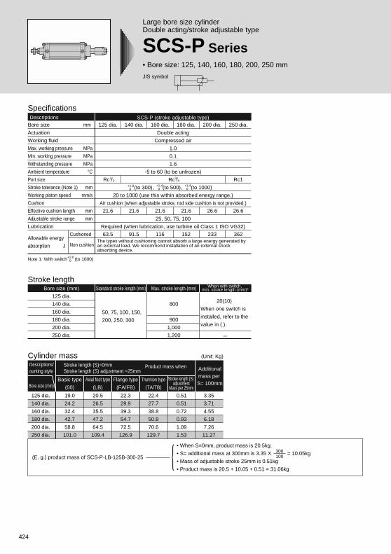
424
JIS symbol
Large bore size cylinderDouble acting/stroke adjustable type
SCS-P Series• Bore size: 125, 140, 160, 180, 200, 250 mm
SpecificationsDescriptions SCS-P (stroke adjustable type)
Bore size mm
Actuation
Working fluid
Max. working pressure MPa
Min. working pressure MPa
Withstanding pressure MPa
Ambient temperature °CPort size
Stroke tolerance (Note 1) mm
Working piston speed mm/s
Cushion
Effective cushion length mm
Adjustable stroke range mm
Lubrication
Cushioned
Non cushion
250 dia.
Rc1
26.6
362
200 dia.
26.6
233
180 dia.
21.6
152
160 dia.
21.6
116
Double acting
Compressed air
1.0
0.1
1.6
-5 to 60 (to be unfrozen)
Rc /
(to 300), (to 500), (to 1000)
20 to 1000 (use this within absorbed energy range.)
Air cushion (when adjustable stroke, rod side cushion is not provided.)
25, 50, 75, 100
Required (when lubrication, use turbine oil Class 1 ISO VG32)
140 dia.
21.6
91.5
125 dia.
Rc /
21.6
63.5
+1.0 0
+1.4 0
+1.4 0
12
34
Note 1: With switch (to 1000)
Stroke lengthBore size (mm)
125 dia.
140 dia.
160 dia.
180 dia.
200 dia.
250 dia.
Standard stroke length (mm) Max. stroke length (mm)
800
900
1,000
1,200
50, 75, 100, 150,
200, 250, 300
When with switch, min. stroke length (mm)*
20(10)
When one switch is
installed, refer to the
value in ( ).
+2.0 0
-
The types without cushioning cannot absorb a large energy generated by an external load. We recommend installation of an external shock absorbing device.
Cylinder mass
Axial foot type
(LB)
125 dia.
140 dia.
160 dia.
180 dia.
200 dia.
250 dia.
Additionalmass per S= 100mmBore size (mm)
Descriptions/ounting style
Stroke length (S)=0mmStroke length (S) adjustment =25mm
Product mass when
20.5
26.5
35.5
47.2
64.5
109.4
Basic type
(00)
19.0
24.2
32.4
42.7
58.8
101.0
Flange type
(FA/FB)
22.3
29.9
39.3
54.7
72.5
126.9
Trunnion type
(TA/TB)
22.4
27.7
38.8
50.8
70.6
129.7
Stroke length (S) adjustment
Mass per 25mm
0.51
0.51
0.72
0.93
1.09
1.53
3.35
3.71
4.55
6.18
7.26
11.27
(Unit: Kg)
(E. g.) product mass of SCS-P-LB-125B-300-25
• When S=0mm, product mass is 20.5kg.
• S= additional mass at 300mm is 3.35 X = 10.05kg
• Mass of adjustable stroke 25mm is 0.51kg
• Product mass is 20.5 + 10.05 + 0.51 = 31.06kg
300100
Allowable energy
absorption J
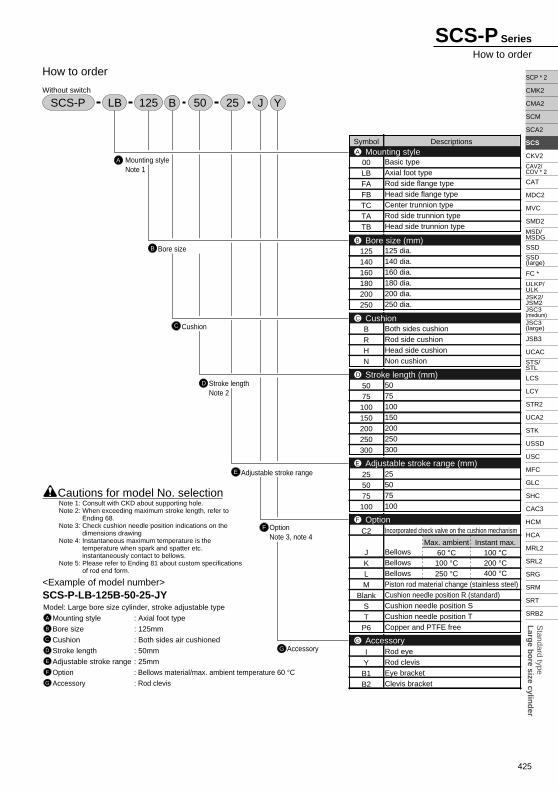
425
Standard type
Larg
e bo
re size cylind
er
SCP * 2
CMK2
CMA2
SCM
SCA2
SCS
CKV2
CAT
MDC2
MVC
SMD2
SSD
FC *
JSB3
UCAC
LCS
LCY
STR2
UCA2
STK
USSD
USC
MFC
GLC
SHC
CAC3
HCM
HCA
MRL2
SRL2
SRG
SRM
SRT
SRB2
CAV2/COV * 2
MSD/MSDG
ULKP/ULKJSK2/JSM2
STS/STL
SSD (large)
JSC3 (medium)JSC3 (large)
SCS-P Series
How to order
A
B
How to order
Mounting styleNote 1
Bore size
C Cushion
D Stroke lengthNote 2
E Adjustable stroke range
F OptionNote 3, note 4
G Accessory
Symbol Descriptions
00LBFAFBTCTATB
125140160180200250
BRHN
5075100150200250300
255075100
C2
JKLM
BlankST
P6
IYB1B2
Basic typeAxial foot typeRod side flange typeHead side flange typeCenter trunnion typeRod side trunnion typeHead side trunnion type
125 dia.140 dia.160 dia.180 dia.200 dia.250 dia.
Both sides cushionRod side cushionHead side cushionNon cushion
5075100150200250300
255075100
Incorporated check valve on the cushion mechanism
BellowsBellowsBellowsPiston rod material change (stainless steel)Cushion needle position R (standard)Cushion needle position SCushion needle position TCopper and PTFE free
Rod eyeRod clevisEye bracketClevis bracket
Mounting styleA
Bore size (mm)B
CushionC
Adjustable stroke range (mm)
Stroke length (mm)
E
D
OptionF
AccessoryG
SCS-P
<Example of model number>SCS-P-LB-125B-50-25-JYModel: Large bore size cylinder, stroke adjustable type
Mounting style : Axial foot type
Bore size : 125mm
Cushion : Both sides air cushioned
Stroke length : 50mm
Adjustable stroke range : 25mmOption : Bellows material/max. ambient temperature 60 °CAccessory : Rod clevis
A
B
C
D
E
F
G
Without switch
LB JB Y50 25125
Cautions for model No. selection
Max. ambient60 °C100 °C250 °C
Instant max.100 °C200 °C400 °C
Note 1: Consult with CKD about supporting hole.Note 2: When exceeding maximum stroke length, refer to
Ending 68.Note 3: Check cushion needle position indications on the
dimensions drawingNote 4: Instantaneous maximum temperature is the
temperature when spark and spatter etc. instantaneously contact to bellows.
Note 5: Please refer to Ending 81 about custom specifications of rod end form.
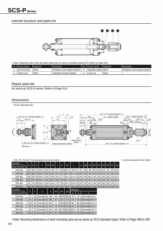
426
74
74
82
91
102
120
b
75
75
80
90
95
120
d
(Stroke length/4.55)+11
(Stroke length/4.55) + 9
(Stroke length/5.15) + 9
(Stroke length/5.15) + 9
(Stroke length/5.30) + 9
(Stroke length/6.40) + 9
Bellows
Internal structure and parts list
Dimensions
Repair parts listAs same as SCS-D series. Refer to Page 414.
1
2
Rod bushing
Piston rod
Parts name
Steel
Steel
Material
Phosphoric acid mangan treatment
Industrial chrome plated
Remarks
Phosphoric acid mangan treatment
No.
3
4
Adjustable stopper
Lock nut
Parts name
Steel
Steel
Material RemarksNo.
• Note: Materials other than the table below are as same as double acting SCS. Refer to Page 404.
50
50
56
63
72
88
A
46
46
55
60
70
85
B
M14 X 1.5
M14 X 1.5
M16 X 1.5
M18 X 1.5
M20 X 1.5
M24 X 1.5
D
47
47
53
60
69
84
C EE
32
36
38.5
39.5
44.5
49.5
GA
57
57
62.5
68.5
75
93
J
140
157
177
200
220
274
K
M30 X 1.5
M30 X 1.5
M36 X 1.5
M40 X 1.5
M45 X 1.5
M56 X 2
KK
83 to 91
91.5 to 99.5
101.5 to 109.5
113 to 121
121 to 131
150 to 158
L
91
102
105
109
122
140
LL
35
35
40
45
50
60
MM
46
46
48.5
53.5
60.5
64.5
PA
35.5
35.5
40
44
48
58
PB
102.5
103
114.5
126.5
140.5
161.5
PC
21
21
26
29
32
39
PD
70
70
80
90
100
115
PE
93
93
106
112
130
152
PF
14.5
16.5
16.5
16.5
17.5
20
QA
12
12
14.5
16
18
22.5
S
18
18
21
24
27
34
T
10 dia. depth 10
10 dia. depth 10
14 dia. depth 15
14 dia. depth 15
14 dia. depth 15
14 dia. depth 15
U
46
46
48.5
53.5
60.5
64.5
V
65
67
71
78
88
94
WF
308.5
322
346.5
376.5
422.5
483.5
XA
258.5
272
290.5
313.5
350.5
395.5
XB
125 dia.
140 dia.
160 dia.
180 dia.
200 dia.
250 dia.
Symbol
Bore size (mm)
125 dia.
140 dia.
160 dia.
180 dia.
200 dia.
250 dia.
Symbol
Bore size (mm)
• Note: R , S and T show position of cushion needle. * a shows adjustable stroke length.
• Note: Mounting dimensions of each mounting style are as same as SCS (standard type). Refer to Page 406 to 409.
• Stroke adjustable type
Rc /
Rc /
Rc /
Rc /
Rc /
Rc1
1
3
3
3
3
2
4
4
4
4
SCS-P Series
1 2 43
MM dia.
J di
a.
4-D2-EE
2-UKK
Width acrossflats B
A WF
T
C GA
L
V
LL + stroke length PC + stroke length + a *
PB + a *
XA + (2 X stroke length) + a *
XB + (2 X stroke length) + a *Cushion adjustment needle
K
N
K N
QA
GA PA PD
PE
dia
.
QA S T
PF
dia
.T
S
R
Stroke length
d di
a.
XA + + (2 X stroke length) + a
XB + + (2 X stroke length) + a
WF +A
b
<Bellows>
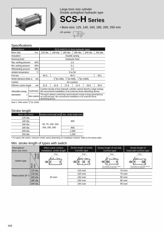
428
JIS symbol
Large bore size cylinderDouble acting/low hydraulic type
SCS-H Series• Bore size: 125, 140, 160, 180, 200, 250 mm
Stroke lengthBore size (mm)
125 dia.
140 dia.
160 dia.
180 dia.
200 dia.
250 dia.
Standard stroke length (mm) Max. stroke length (mm)
800
900
1,000
1,200
50, 75, 100, 150,
200, 250, 300
SpecificationsDescriptions SCS-H/SCS-LH (low hydraulic type)
Bore size mm
Actuation
Working fluid
Max. working pressure MPa
Min. working pressure MPa
Withstanding pressure MPa
Ambient temperature °CPort size
Stroke tolerance (Note 1) mm
Cushion
Effective cushion length mm
250 dia.
Rc1
26.6
200 dia.
26.6
180 dia.
21.6
160 dia.
21.6
Double acting
Hydraulic fluid
1.0
0.1
1.6
5 to 50
Rc /
(to 300), (to 500), (to 1000)
Air cushion
140 dia.
21.6
125 dia.
Rc /
21.6
+1.0 0
+1.4 0
+1.4 0
12
34
Note 1: With switch (to 1000)
* For types with switch, minimum stroke varies depending on installation method. Refer to the below table.
+2.0 0
The types without cushioning cannot absorb a large energy generated by an external load. We recommend installation of an external shock absorbing device.
Min. stroke length of types with switch
20 over
125 dia.
140 dia.
160 dia.
180 dia.
200 dia.
120 over
125 over
130 over
135 over
140 over
The position at rod side stroke end cannot be detected.
The position at head side stroke end cannot be detected.
When same surfaceinstallation, stroke length
DescriptionsBore size (mm)
Switch type
Rou
ghsk
etch
Bor
esi
ze
Reed switch (R *)
Stroke length of centertrunnion type
Stroke length of rod side trunnion type
Stroke length ofhead side trunnion type
70 over
75 over
80 over
85 over
90 over
Port PortPort Port
Cushion faculty of low hydraulic cylinder cannot absorb a large energy. We recommend installation of an external shock absorbing device.Allowable energy
absorption J
Cushioned
Non cushion
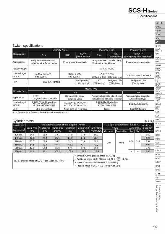
429
Standard type
Larg
e bo
re size cylind
er
SCP * 2
CMK2
CMA2
SCM
SCA2
SCS
CKV2
CAT
MDC2
MVC
SMD2
SSD
FC *
JSB3
UCAC
LCS
LCY
STR2
UCA2
STK
USSD
USC
MFC
GLC
SHC
CAC3
HCM
HCA
MRL2
SRL2
SRG
SRM
SRT
SRB2
CAV2/COV * 2
MSD/MSDG
ULKP/ULKJSK2/JSM2
STS/STL
SSD (large)
JSC3 (medium)JSC3 (large)
SCS-H Series
Specifications
Note: Please refer to Ending 1 about other switch specifications.
R1K
R0 R4 R5 R6
LED ON lighting Neon light OFF lighting None LED ON lighting
DC12/24V, 5 to 50mA or lessAC110V, 7 to 20mA or lessAC220V, 7 to 10mA or less
AC110V, 20 to 200mAAC220V, 10 to 200mA
DC5/12/24V, 50mA or lessAC110V, 20mA or lessAC220V, 10mA or less
DC24V, 5 to 50mA
High capacity relay, solenoid valve
Relay, programmable controller
Programmable controller, relay, IC circuit(without indicator light), serial connection
Programmable controller(DC self hold type)
Applications
Power voltage
Load voltage/current
Light
Descriptions
Proximity 2 wire Proximity 2 wire
Reed 2 wire
Proximity 3 wire
Applications
Load voltage/current
Light
Descriptions
R2KR2YK
(2 color indicator)
Red/green LED(ON lighting)
R3KR3YK
(2 color indicator)
200mA or less 150mA or less
T2YDP *(Strong magnetic field proof)
LED (ON lighting)LED
(ON lighting)Red/green LED
(ON lighting)Red/green LED
(ON lighting)
AC85V to 265V5 to 100mA
DC10 to 30V5 to 300mA DC24V ± 10%, 5 to 20mA
Programmable controller, relay, small solenoid valve Programmable controller
Programmable controller, relay, IC circuit, solenoid valve Programmable controller
- - DC4.5V to 28V
DC30V or less
-
Switch specifications
Cylinder mass
Axial foot type
(LB)
125 dia.
140 dia.
160 dia.
180 dia.
200 dia.
250 dia.
Additional mass per S= 100mmBore size (mm)
Descriptions/mounting style Product mass when stroke length (S) =0mm Mass per switch (bracket included)
16.3
22.2
29.4
39.3
53.3
92.1
Basic type
(00)
14.8
20.2
26.3
34.8
47.6
83.7
Flange type
(FA/FB)
18.1
25.6
33.2
46.8
61.3
109.6
Eye bracket
(CA)
17.8
24.0
31.3
42.2
57.1
107.7
Clevis bracket
(CB)
17.9
24.2
31.6
42.7
57.3
102.2
Trunnion type
(TA/TB/TC)
18.2
23.4
32.7
42.9
59.4
112.4
Grommet
0.04
Terminal boxR type
0.03
T2YD (strongmagnetic field proof)
0.09
1m 3m
0.17
- -
2.60
2.96
3.57
4.94
5.73
9.06
(Unit: Kg)(Unit: Kg)
(E. g.) product mass of SCS-H-LB-125B-300-R0-D
• When S=0mm, product mass is 16.3kg.
• Additional mass at S= 300mm is 2.60 X =7.8kg
• Mass of two switches is 0.04 X 2 = 0.08kg.
• Product mass is 16.3 + 7.8 + 0.08 = 24.18kg
300100
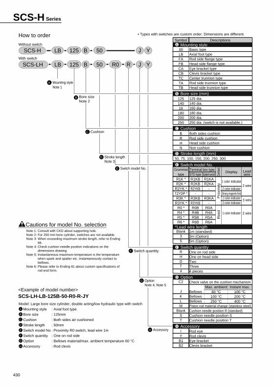
430
• Types with switches are custom order. Dimensions are different.
<Example of model number>SCS-LH-LB-125B-50-R0-R-JYModel: Large bore size cylinder, double acting/low hydraulic type with switch
Mounting style : Axial foot type
Bore size : 125mm
Cushion : Both sides air cushioned
Stroke length : 50mm
Switch model No : Proximity R0 switch, lead wire 1m
Switch quantity : One on rod side
Option : Bellows material/max. ambient temperature 60 °CAccessory : Rod clevis
A
B
C
D
E
F
G
H
Cautions for model No. selection
A
How to order
Without switch
With switch
Mounting styleNote 1
B Bore sizeNote 2
C Cushion
D Stroke lengthNote 3
E Switch model No.
G OptionNote 4, Note 5
F Switch quantity
H Accessory
SCS-LH LB 50125 B JR YR0
LB 50125 B J YSCS-H
Symbol Descriptions
00LBFAFBCACBTCTATB
12514016180200250
BRHN
Blank35
RHDT4
C2
JKLM
BlankST
IYB1B2
Mounting styleA
Bore size (mm)B
CushionC
Stroke length (mm)D
Switch model No.E
*Lead wire length
OptionG
AccessoryH
Switch quantityF
Basic typeAxial foot typeRod side flange typeHead side flange typeEye bracket typeClevis bracket typeCenter trunnion typeRod side trunnion typeHead side trunnion type
125 dia.140 dia.160 dia.180 dia.200 dia.250 dia. (switch is not available.)
Both sides cushionRod side cushionHead side cushionNon cushion
1m (standard)3m (Option)5m (Option)
One on rod sideOne on head sideTwoThree4 pieces
Check valve on the cushion mechanism
BellowsBellowsBellowsPiston rod material change (stainless steel)Cushion needle position R (standard)Cushion needle position SCushion needle position T
Rod eyeRod clevisEye bracketClevis bracket
50, 75, 100, 150, 200, 250, 300
Leadwire
2 wire
3 wire
2 wireCo
ntac
tP
roxi
mity
Ree
d
Terminal box typeDisplay
1 color indicator
2 color indicatorStrong magnetic field1 color indicator2 color indicator
1 color indicator
STD typeR1KBR2KBR2YKB
-R3KBR3YKBR0BR4BR5BR6B
Splash-proofR1KAR2KA
--
R3KA-
R0AR4AR5AR6A
Grommettype
R1K *R2K *
R2YK *T2YDP *R3K *
R3YK *R0 *R4 *R5 *R6 *
Max. ambient60 °C
100 °C250 °C
Instant max.100 °C200 °C400 °C
Note 1: Consult with CKD about supporting hole.Note 2: For 250 mm bore cylinder, switches are not available.Note 3: When exceeding maximum stroke length, refer to Ending
68.Note 4: Check cushion needle position indications on the
dimensions drawingNote 5: Instantaneous maximum temperature is the temperature
when spark and spatter etc. instantaneously contact to bellows.
Note 6: Please refer to Ending 81 about custom specifications of rod end form.
SCS-H Series
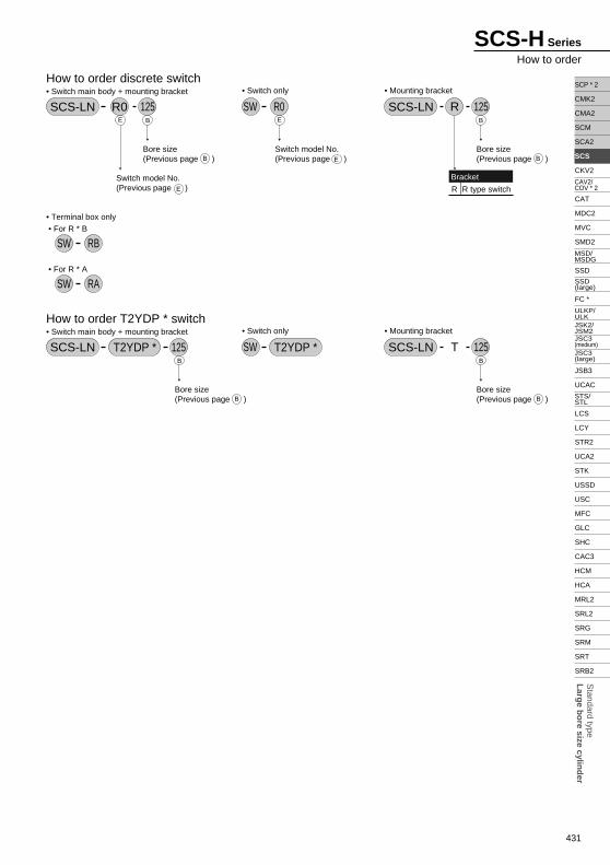
431
Standard type
Larg
e bo
re size cylind
er
SCP * 2
CMK2
CMA2
SCM
SCA2
SCS
CKV2
CAT
MDC2
MVC
SMD2
SSD
FC *
JSB3
UCAC
LCS
LCY
STR2
UCA2
STK
USSD
USC
MFC
GLC
SHC
CAC3
HCM
HCA
MRL2
SRL2
SRG
SRM
SRT
SRB2
CAV2/COV * 2
MSD/MSDG
ULKP/ULKJSK2/JSM2
STS/STL
SSD (large)
JSC3 (medium)JSC3 (large)
SCS-H Series
How to order
Switch model No.(Previous page )
How to order discrete switch• Switch main body + mounting bracket
SCS-LN R0 125
B
B B
B
E E
E
E
Bore size(Previous page )
B
B
Bore size(Previous page ) B
B
Bore size(Previous page )
Switch model No.(Previous page )
• Mounting bracket
SCS-LN 125R
Bore size(Previous page )
Bracket
R R type switch
• Switch only
SW R0
How to order T2YDP * switch• Switch main body + mounting bracket
T2YDP * 125• Mounting bracket
SCS-LN 125T• Switch only
SWSCS-LN T2YDP *
• Terminal box only • For R * B
SW RB
• For R * A
SW RA
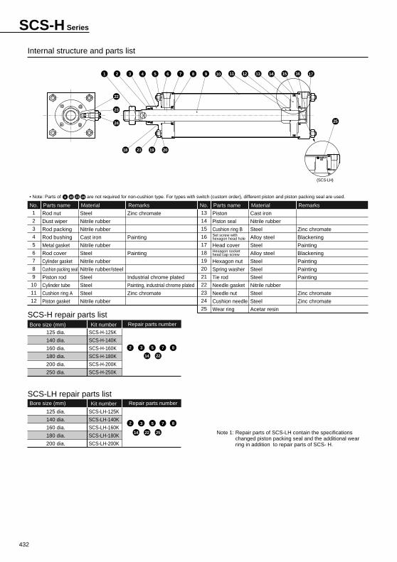
432
1
2
3
4
5
6
7
8
9
10
11
12
Rod nut
Dust wiper
Rod packing
Rod bushing
Metal gasket
Rod cover
Cylinder gasket
Cushion packing seal
Piston rod
Cylinder tube
Cushion ring A
Piston gasket
Parts name
Steel
Nitrile rubber
Nitrile rubber
Cast iron
Nitrile rubber
Steel
Nitrile rubber
Nitrile rubber/steel
Steel
Steel
Steel
Nitrile rubber
Material
Zinc chromate
Painting
Painting
Industrial chrome plated
Painting, industrial chrome plated
Zinc chromate
Remarks
Zinc chromate
Blackening
Painting
Blackening
Painting
Painting
Painting
Zinc chromate
Zinc chromate
No.13
14
15
16
17
18
19
20
21
22
23
24
25
Piston
Piston seal
Cushion ring BSet screw with hexagon head hole
Head coverHexagon socket head cap screw
Hexagon nut
Spring washer
Tie rod
Needle gasket
Needle nut
Cushion needle
Wear ring
Parts name
Cast iron
Nitrile rubber
Steel
Alloy steel
Steel
Alloy steel
Steel
Steel
Steel
Nitrile rubber
Steel
Steel
Acetar resin
Material RemarksNo.
SCS-H repair parts list
SCS-LH repair parts list
• Note: Parts of are not required for non-cushion type. For types with switch (custom order), different piston and piston packing seal are used.
Note 1: Repair parts of SCS-LH contain the specifications changed piston packing seal and the additional wear ring in addition to repair parts of SCS- H.
Internal structure and parts list
Bore size (mm) Kit number Repair parts number
125 dia.
140 dia.
160 dia.
180 dia.
200 dia.
SCS-LH-125K
SCS-LH-140K
SCS-LH-160K
SCS-LH-180K
SCS-LH-200K
22 2514
Bore size (mm) Kit number Repair parts number
125 dia.
140 dia.
160 dia.
180 dia.
200 dia.
250 dia.
SCS-H-125K
SCS-H-140K
SCS-H-160K
SCS-H-180K
SCS-H-200K
SCS-H-250K
2 3 5 7 8
2 3 5 7 8
14 22
22 24238
(SCS-LH)
6 981 102
22
23
24
74 53 11 12 13 14 15 16 17
18 21 19 20
25
SCS-H Series
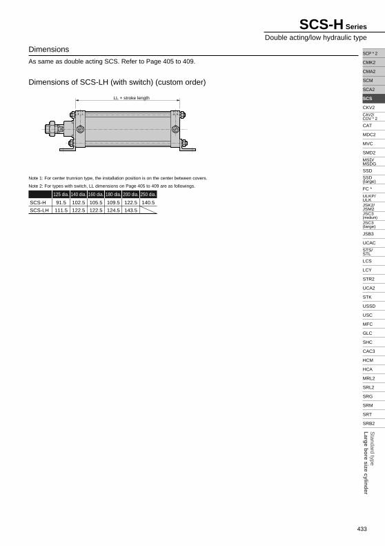
433
Standard type
Larg
e bo
re size cylind
er
SCP * 2
CMK2
CMA2
SCM
SCA2
SCS
CKV2
CAT
MDC2
MVC
SMD2
SSD
FC *
JSB3
UCAC
LCS
LCY
STR2
UCA2
STK
USSD
USC
MFC
GLC
SHC
CAC3
HCM
HCA
MRL2
SRL2
SRG
SRM
SRT
SRB2
CAV2/COV * 2
MSD/MSDG
ULKP/ULKJSK2/JSM2
STS/STL
SSD (large)
JSC3 (medium)JSC3 (large)
SCS-H Series
Double acting/low hydraulic type
Dimensions of SCS-LH (with switch) (custom order)
Note 1: For center trunnion type, the installation position is on the center between covers.
125 dia. 140 dia. 160 dia. 180 dia. 200 dia. 250 dia.
91.5
111.5
SCS-H
SCS-LH
102.5
122.5
105.5
122.5
109.5
124.5
122.5
143.5
140.5
Dimensions
As same as double acting SCS. Refer to Page 405 to 409.
Note 2: For types with switch, LL dimensions on Page 405 to 409 are as followings.
LL + stroke length
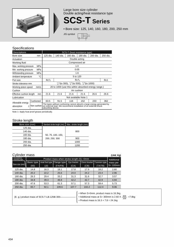
434
JIS symbol
Large bore size cylinderDouble acting/heat resistance type
SCS-T Series• Bore size: 125, 140, 160, 180, 200, 250 mm
SpecificationsDescriptions SCS-T (heat resistance type)
Bore size mm
Actuation
Working fluid
Max. working pressure MPa
Min. working pressure MPa
Withstanding pressure MPa
Ambient temperature °CPort size
Stroke tolerance mm
Working piston speed mm/s
Cushion
Effective cushion length mm
Lubrication
250 dia.
Rc1
26.6
362
200 dia.
26.6
233
180 dia.
21.6
152
160 dia.
21.6
116
Double acting
Compressed air
1.0
0.05
1.6
5 to 120
Rc /
(to 300), (to 500), (to 1000)
20 to 1000 (use this within absorbed energy range.)
Air cushion
Not available Note 1
140 dia.
21.6
91.5
125 dia.
Rc /
21.6
63.5
+1.0 0
+1.4 0
+1.4 0
12
34
Stroke lengthBore size (mm)
125 dia.
140 dia.
160 dia.
180 dia.
200 dia.
250 dia.
Standard stroke length (mm) Max. stroke length (mm)
800
900
1000
1200
50, 75, 100, 150,
200, 250, 300
The types without cushioning cannot absorb a large energy generated by an external load. We recommend installation of an external shock absorbing device.
Cylinder mass
Axial foot type
(LB)
125 dia.
140 dia.
160 dia.
180 dia.
200 dia.
250 dia.
Additionalmass per S= 100mmBore size (mm)
Descriptions/mounting style Product mass when stroke length (S) =0mm
16.3
22.2
29.4
39.3
53.3
92.1
Basic type
(00)
14.8
20.2
26.3
34.8
47.6
83.7
Flange type
(FA/FB)
18.1
25.6
33.2
46.8
61.3
109.6
Eye bracket
(CA)
17.8
24.0
31.3
42.2
57.1
107.7
Clevis bracket
(CB)
17.9
24.2
31.6
42.7
57.3
102.2
Trunnion type
(TA/TB)
18.2
23.4
32.7
42.9
59.4
112.4
2.60
2.96
3.57
4.94
5.73
9.06
(Unit: Kg)(Unit: Kg)
(E. g.) product mass of SCS-T-LB-125B-300
• When S=0mm, product mass is 16.3kg.
• Additional mass at S= 300mm is 2.60 X =7.8kg
• Product mass is 16.3 + 7.8 = 24.1kg
300100
Note 1: Apply heat proof grease periodically.
Allowable energy
absorption J
Cushioned
Non cushion
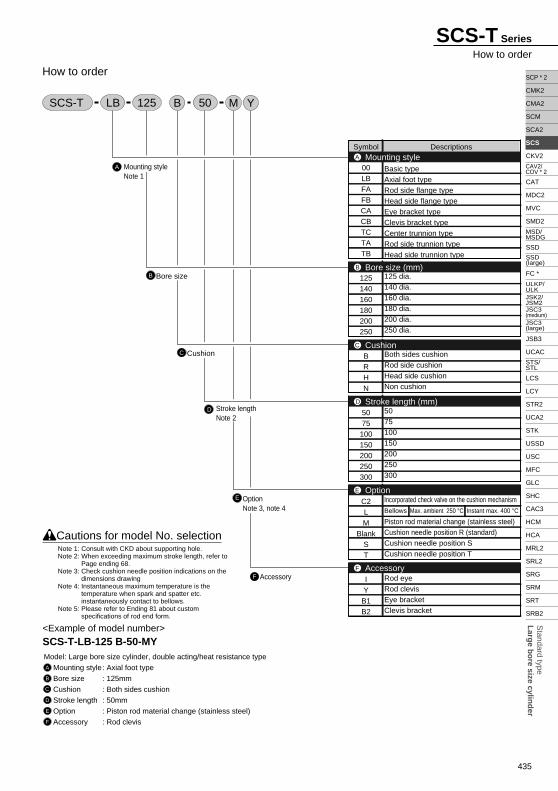
435
Standard type
Larg
e bo
re size cylind
er
SCP * 2
CMK2
CMA2
SCM
SCA2
SCS
CKV2
CAT
MDC2
MVC
SMD2
SSD
FC *
JSB3
UCAC
LCS
LCY
STR2
UCA2
STK
USSD
USC
MFC
GLC
SHC
CAC3
HCM
HCA
MRL2
SRL2
SRG
SRM
SRT
SRB2
CAV2/COV * 2
MSD/MSDG
ULKP/ULKJSK2/JSM2
STS/STL
SSD (large)
JSC3 (medium)JSC3 (large)
SCS-T Series
How to order
A
B
How to order
Mounting styleNote 1
Bore size
C Cushion
D Stroke lengthNote 2
E OptionNote 3, note 4
F Accessory
Symbol Descriptions
00LBFAFBCACBTCTATB
125140160180200250
BRHN
5075
100150200250300
C2LM
BlankST
IY
B1B2
Basic typeAxial foot typeRod side flange typeHead side flange typeEye bracket typeClevis bracket typeCenter trunnion typeRod side trunnion typeHead side trunnion type
125 dia.140 dia.160 dia.180 dia.200 dia.250 dia.
Both sides cushionRod side cushionHead side cushionNon cushion
5075100150200250300
Incorporated check valve on the cushion mechanismBellows Max. ambient 250 °C Instant max. 400 °C
Piston rod material change (stainless steel)Cushion needle position R (standard)Cushion needle position SCushion needle position T
Rod eyeRod clevisEye bracketClevis bracket
Mounting styleA
Bore size (mm)B
CushionC
Stroke length (mm)D
OptionE
AccessoryF
SCS-T
<Example of model number>SCS-T-LB-125 B-50-MYModel: Large bore size cylinder, double acting/heat resistance type
Mounting style: Axial foot type
Bore size : 125mm
Cushion : Both sides cushion
Stroke length : 50mm
Option : Piston rod material change (stainless steel)
Accessory : Rod clevis
A
B
C
D
E
F
Cautions for model No. selection
LB MB Y50125
Note 1: Consult with CKD about supporting hole.Note 2: When exceeding maximum stroke length, refer to
Page ending 68.Note 3: Check cushion needle position indications on the
dimensions drawingNote 4: Instantaneous maximum temperature is the
temperature when spark and spatter etc. instantaneously contact to bellows.
Note 5: Please refer to Ending 81 about custom specifications of rod end form.
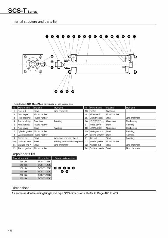
436
Internal structure and parts list
Dimensions
As same as double acting/single rod type SCS dimensions. Refer to Page 405 to 409.
1
2
3
4
5
6
7
8
9
10
11
12
Rod nut
Dust wiper
Rod packing
Rod bushing
Metal gasket
Rod cover
Cylinder gasket
Cushion packing seal
Piston rod
Cylinder tube
Cushion ring A
Piston gasket
Parts name
Steel
Fluoro rubber
Fluoro rubber
Cast iron
Fluoro rubber
Steel
Fluoro rubber
Fluoro rubber
Steel
Steel
Steel
Fluoro rubber
Material
Zinc chromate
Painting
Painting
Industrial chrome plated
Painting, industrial chrome plated
Zinc chromate
Remarks
Zinc chromate
Blackening
Painting
Blackening
Painting
Painting
Painting
Zinc chromate
Zinc chromate
No.
13
14
15
16
17
18
19
20
21
22
23
24
Piston
Piston seal
Cushion ring B
Head cover
Hexagon nut
Spring washer
Tie rod
Needle gasket
Needle nut
Cushion needle
Parts name
Cast iron
Fluoro rubber
Steel
Alloy steel
Steel
Alloy steel
Steel
Steel
Steel
Fluoro rubber
Steel
Steel
Material RemarksNo.
Repair parts list
• Note: Parts of and are not required for non-cushion type.
Bore size (mm) Kit number Repair parts number
125 dia.
140 dia.
160 dia.
180 dia.
200 dia.
250 dia.
SCS-T-125K
SCS-T-140K
SCS-T-160K
SCS-T-180K
SCS-T-200K
SCS-T-250K
2 3 5 7 8
14 22
Set screw with hexagon head hole
Hexagon socket head cap screw
22 24238
SCS-T Series
6 981 102
22
23
24
74 53 11 12 13 14 15 16 17
18 21 19 20

438
JIS symbol
Large bore size cylinderDouble acting/heavy duty scraper type
SCS-G Series• Bore size: 125, 140, 160, 180, 200, 250 mm
SpecificationsDescriptions SCS-G (heavy duty scraper type)
Bore size mm
Actuation
Working fluid
Max. working pressure MPa
Min. working pressure MPa
Withstanding pressure MPa
Ambient temperature °CPort size
Stroke tolerance mm
Working piston speed mm/s
Cushion
Effective cushion length mm
Lubrication
Cushioned
Non cushion
250 dia.
Rc1
26.6
362
200 dia.
26.6
233
180 dia.
21.6
152
160 dia.
21.6
116
Double acting
Compressed air
1.0
0.05
1.6
-5 to 60 (to be unfrozen)
Rc /
(to 300), (to 500), (to 1000)
20 to 1000 (use this within absorbed energy range.)
Air cushion
Required (when lubrication, use turbine oil Class 1 ISO VG32)
140 dia.
21.6
91.5
125 dia.
Rc /
21.6
63.5
+1.0 0
+1.4 0
+1.4 0
12
34
Stroke lengthBore size (mm)
125 dia.
140 dia.
160 dia.
180 dia.
200 dia.
250 dia.
Standard stroke length (mm) Max. stroke length (mm)
800
900
1,000
1,200
50, 75, 100, 150,
200, 250, 300
When types with switch, min. stroke length (mm)
20(10)
When one switch is
installed, refer to the
value in ( ).
-
The types without cushioning cannot absorb a large energy generated by an external load. We recommend installation of an external shock absorbing device.
Cylinder mass
Axial foot type
(LB)
125 dia.
140 dia.
160 dia.
180 dia.
200 dia.
250 dia.
Additionalmass per S= 100mmBore size (mm)
Descriptions/mounting style Product mass when stroke length (S) =0mm
16.3
22.2
29.4
39.3
53.3
92.1
Basic type
(00)
14.8
20.0
26.3
34.8
47.6
83.7
Flange type
(FA/FB)
18.1
25.6
33.2
46.8
61.3
109.6
Eye bracket
(CA)
17.8
24.0
31.3
42.2
57.1
107.7
Clevis bracket
(CB)
17.9
24.2
31.6
42.7
57.3
102.2
Trunnion type
(TA/TB/TC)
18.2
23.4
32.7
42.9
59.4
112.4
2.60
2.96
3.57
4.94
5.73
9.06
(Unit: Kg)
(E. g.) product mass of SCS-G-LB-125B-300• When S=0mm, product mass is 16.3kg.
• Additional mass at S= 300mm is 2.60 X =7.8kg
• Product mass is 16.3 + 7.8 = 24.1kg
300100
Dimensions
As same as double acting/standard single rod type SCS. Refer to Page 405 to 409.
Allowable energy
absorption J
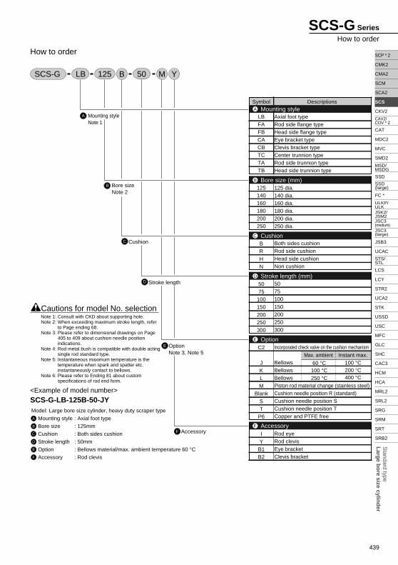
439
Standard type
Larg
e bo
re size cylind
er
SCP * 2
CMK2
CMA2
SCM
SCA2
SCS
CKV2
CAT
MDC2
MVC
SMD2
SSD
FC *
JSB3
UCAC
LCS
LCY
STR2
UCA2
STK
USSD
USC
MFC
GLC
SHC
CAC3
HCM
HCA
MRL2
SRL2
SRG
SRM
SRT
SRB2
CAV2/COV * 2
MSD/MSDG
ULKP/ULKJSK2/JSM2
STS/STL
SSD (large)
JSC3 (medium)JSC3 (large)
SCS-G Series
How to order
A
B
How to order
Mounting styleNote 1
Bore sizeNote 2
C Cushion
D Stroke length
E OptionNote 3, Note 5
F Accessory
Symbol Descriptions
LBFAFBCACBTCTATB
125140160180200250
BRHN
5075
100150200250300
C2
JKLM
BlankST
P6
IY
B1B2
Axial foot typeRod side flange typeHead side flange typeEye bracket typeClevis bracket typeCenter trunnion typeRod side trunnion typeHead side trunnion type
125 dia.140 dia.160 dia.180 dia.200 dia.250 dia.
Both sides cushionRod side cushionHead side cushionNon cushion
5075100150200250300
Incorporated check valve on the cushion mechanism
BellowsBellowsBellowsPiston rod material change (stainless steel)Cushion needle position R (standard)Cushion needle position SCushion needle position TCopper and PTFE free
Rod eyeRod clevisEye bracketClevis bracket
Mounting styleA
Bore size (mm)B
CushionC
Stroke length (mm)D
OptionE
AccessoryF
SCS-G LB MB Y50125
<Example of model number>SCS-G-LB-125B-50-JYModel: Large bore size cylinder, heavy duty scraper type
Mounting style : Axial foot type
Bore size : 125mm
Cushion : Both sides cushion
Stroke length : 50mm
Option : Bellows material/max. ambient temperature 60 °CAccessory : Rod clevis
A
B
C
D
E
F
Cautions for model No. selection
Max. ambient
60 °C100 °C250 °C
Instant max.100 °C200 °C400 °C
Note 1: Consult with CKD about supporting hole.Note 2: When exceeding maximum stroke length, refer
to Page ending 68.Note 3: Please refer to dimensional drawings on Page
405 to 409 about cushion needle position indications.
Note 4: Rod metal bush is compatible with double acting single rod standard type.
Note 5: Instantaneous maximum temperature is the temperature when spark and spatter etc. instantaneously contact to bellows.
Note 6: Please refer to Ending 81 about custom specifications of rod end form.
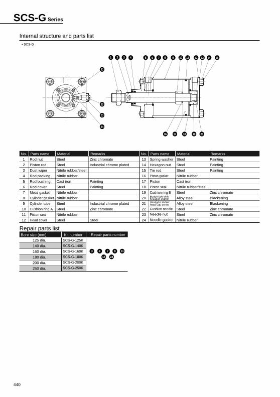
440
Internal structure and parts list
1
2
3
4
5
6
7
8
9
10
11
12
Rod nut
Piston rod
Dust wiper
Rod packing
Rod bushing
Rod cover
Metal gasket
Cylinder gasket
Cylinder tube
Cushion ring A
Piston seal
Head cover
Parts name
Steel
Steel
Nitrile rubber/steel
Nitrile rubber
Cast iron
Steel
Nitrile rubber
Nitrile rubber
Steel
Steel
Nitrile rubber
Steel
Material
Zinc chromate
Industrial chrome plated
Painting
Painting
Industrial chrome plated
Zinc chromate
Steel
Remarks
Painting
Painting
Painting
Zinc chromate
Blackening
Blackening
Zinc chromate
Zinc chromate
No.
13
14
15
16
17
18
19
20
21
22
23
24
Spring washer
Hexagon nut
Tie rod
Piston gasket
Piston
Piston seal
Cushion ring BButton bolt withhexagon indentHexagon socket head cap screw
Cushion needle
Needle nut
Needle gasket
Parts name
Steel
Steel
Steel
Nitrile rubber
Cast iron
Nitrile rubber/steel
Steel
Alloy steel
Alloy steel
Steel
Steel
Nitrile rubber
Material RemarksNo.
Repair parts list
• SCS-G
Bore size (mm) Kit number Repair parts number
125 dia.
140 dia.
160 dia.
180 dia.
200 dia.
250 dia.
SCS-G-125K
SCS-G-140K
SCS-G-160K
SCS-G-180K
SCS-G-200K
SCS-G-250K
3 4 7 8 11
18 24
SCS-G Series
1 2 3 4 5 6 7 8 9 10 11 12 13 14 15
16
21
22
23
24
17 18 19 20
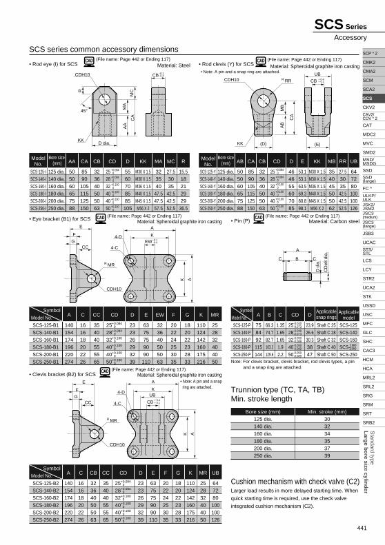
441
Standard type
Larg
e bo
re size cylind
er
SCP * 2
CMK2
CMA2
SCM
SCA2
SCS
CKV2
CAT
MDC2
MVC
SMD2
SSD
FC *
JSB3
UCAC
LCS
LCY
STR2
UCA2
STK
USSD
USC
MFC
GLC
SHC
CAC3
HCM
HCA
MRL2
SRL2
SRG
SRM
SRT
SRB2
CAV2/COV * 2
MSD/MSDG
ULKP/ULKJSK2/JSM2
STS/STL
SSD (large)
JSC3 (medium)JSC3 (large)
(File name: Page 442 or Ending 117)• Rod eye (I) for SCS Material: Steel
SCS-125-ISCS-140-ISCS-160-ISCS-180-ISCS-200-ISCS-250-I
ModelNo.
125 dia.140 dia.160 dia.180 dia.200 dia.250 dia.
Bore size (mm)
505060657588
AA
8590
105115125150
CA
323640505063
CB
252832404050
+0.084 0+0.084 0+0.100 0+0.100 0+0.100 0+0.100 0
CD
5560708585105
D
M30 X 1.5M30 X 1.5M36 X 1.5M40 X 1.5M45 X 1.5M56 X 2
KK
323540
47.547.557.5
MA
27.53035
42.542.552.5
MC
15.518212929
36.5
R
(File name: Page 442 or Ending 117)• Eye bracket (B1) for SCS Material: Spheroidal graphite iron casting
SCS-125-B1SCS-140-B1SCS-160-B1SCS-180-B1SCS-200-B1SCS-250-B1
140154174196220274
A
161618202226
C
354040555565
CC CD
232326293239
D
6375759090110
E
323640505063
EW
202224253035
F
182022232833
G
110124142160175216
K
252832404050
MR
(File name: Page 442 or Ending 117)• Rod clevis (Y) for SCS Material: Spheroidal graphite iron casting
SCS-125-YSCS-140-YSCS-160-YSCS-180-YSCS-200-YSCS-250-Y
ModelNo.
125 dia.140 dia.160 dia.180 dia.200 dia.250 dia.
Bore size(mm)
505060657588
AB
464655607085
D
53.153.163.569.380.898.1
E
354045505062
MB
27.5303542.542.552.5
RR
647280100100126
UB
8590105115125150
CA
323640505063
CB
252832404050
+0.084 0+0.084 0+0.100 0+0.100 0+0.100 0+0.100 0
CD
M30 X 1.5M30 X 1.5M36 X 1.5M40 X 1.5M45 X 1.5M56 X 2
KK
• Note: A pin and a snap ring are attached.
SymbolModel No.
252832404050
+0.084 0+0.084 0+0.100 0+0.100 0+0.100 0+0.100 0
(File name: Page 442 or Ending 117)• Clevis bracket (B2) for SCS Material: Spheroidal graphite iron casting
SCS-125-B2SCS-140-B2SCS-160-B2SCS-180-B2SCS-200-B2SCS-250-B2
140154174196220274
A
161618202226
C
323640505063
CB
354040555565
CC
232326293239
D
6375759090110
E
202224253035
F
182022232833
G
110124142160175216
K
252832404050
MR
647280100100126
UBSymbol
Model No.
(File name: Page 442 or Ending 117)• Pin (P)
Trunnion type (TC, TA, TB)Min. stroke length
Cushion mechanism with check valve (C2)
Material: Carbon steel
SCS-125-PSCS-140-PSCS-160-PSCS-180-PSCS-250-P
758492115144
Bore size (mm)125 dia.140 dia.160 dia.180 dia.200 dia.250 dia.
Min. stroke (mm)303234353739
A
66.374.782.7103.2129.6
B
1.351.651.651.92.2
C
23.926.630.33847
D
Shaft C 25Shaft C 28Shaft C 32Shaft C 40Shaft C 50
Applicablesnap rings
SCS-125SCS-140SCS-160SCS-180SCS-250
Applicablemodel
SymbolModel No. CD
2528324050
-0.040-0.073-0.040-0.073-0.050-0.089-0.050-0.089-0.050-0.089
Note: For clevis bracket, clevis bracket, rod clevis types, a pin and a snap ring are attached.
180200
CD
252832404050
+0.084 0+0.084 0+0.100 0+0.100 0+0.100 0+0.100 0
Larger load results in more delayed starting time. When
quick starting time is required, use the check valve
integrated cushion mechanism (C2).
• Note: A pin and a snap ring are attached.
SCS series common accessory dimensions
CDH10
R MR
4-D
4-C
E
CC
F
CB
UB G+ 0.4+ 0.1
AK
A
K
CDH10
MB
R RR
KK
UB
(E) (D)
CB + 0.4+ 0.1
AB
CA
MC
CDH10
KK
CA
MA
R
AA
D dia.
CB -0.4-0.1
45°
D d
ia.
CD
e8 d
ia.
BC C
A
SCS Series
Accessory
CDH10
R MR
4-D
4-C
E
CC
F
EW G -0.1-0.4
AK
A
K
![Air Servo Cylinder air.pdf · How to Order Bore size 125 125 mm 160 160 mm 200 200 mm 250 250 mm 320 320 mm Stroke [mm] 125 250 160 200, 300 200 200, 300 250 350, 450 320 200, 350,](https://img.pdfslide.us/doc/110x75/60c57874778cca0a96064de1/air-servo-cylinder-airpdf-how-to-order-bore-size-125-125-mm-160-160-mm-200-200.jpg)