Embed Size (px)
Citation preview
Miami-Dade Limestone Products Association 13292 N.W. 118th Avenue Miami, FL 33178 December 2011
SCOPE OF WORK Construction of Phase 1 Cement-Bentonite Seepage Barrier
L-31N Canal, Miami-Dade County Florida Prepared on behalf of the Miami-Dade Limestone Products Association by MacVicar, Federico & Lamb, Inc./AMEC-BCI Engineers & Scientists, Inc.
Background Recent investigations by the U.S. Geological Survey documented the distinct layering within the Biscayne Aquifer, with highly conductive horizontal flow zones separated by much denser limestone strata. One of the high flow layers is the Miami Limestone, which makes up the top 10 to 15 feet of the aquifer. Other high flow zones exist in the underlying Fort Thompson formation. The upper layers of porous rock appear to transmit much of the water from the wetlands within the adjacent Everglades National Park (ENP) to the L-31N Canal. The goal of the Phase 1 seepage barrier is to document, in the field, the performance of a partially penetrating flow barrier in reducing groundwater interception by the canal. The test will consist of constructing a flow barrier in a narrow trench excavated through the Miami Limestone and Upper Ft. Thompson formations of the aquifer just west of the L-31N Canal. The test barrier will start just south of Tamiami Trail (US Highway 41) and proceed south for two miles, as shown on the project plans. General Test Description The seepage barrier, consisting of a cement-bentonite (CB) slurry wall 2-miles long will be constructed in a 32-inch wide trench excavated to a depth of 35 feet below ground surface using a large chain-type trenching machine. After the trench is excavated, it will be backfilled with excavated sand and rock fragments (4 inches maximum dimension). Using a track hoe, the trench will be re-excavated in panels and simultaneously backfilled with CB slurry prepared in a mixing plant and pumped to the trench location. In order to ensure that the barrier is homogeneous and consistent throughout the full depth, an air lift pump will be utilized behind the track hoe to clean the bottom of the trench of any sediment. In addition, the CB mix will utilize approximately 35% more bentonite and cement than a conventional mix for similar geologic conditions. Further, the Quality Control/Quality Assurance program will be considerably more extensive than normally employed, involving closely-spaced probing of slurry depth, and frequent testing and sampling of the slurry to confirm that project specifications are met throughout the entire depth of the barrier wall.
Scope of Work Construction of Phase 1Cement-Bentonite Seepage Barrier L-31N The Project will be constructed and completed in accordance with the plans and specifications prepared by AMEC-BCI Engineers and Scientists, Inc. (Engineer of Record for the Slurry Wall), which are attached to this Scope of Work as Appendices A and B, respectively. The Owner of the Project is the Miami Dade Limestone Products Association, Inc. (MDLPA) and the Project Engineer of Record is MacVicar Federico & Lamb, Inc. Compliance with SFWMD Right-Of-Way Permit The project will be constructed adjacent to the L-31N levee, south of Tamiami Trail (US Highway 41), on property owned by the South Florida Water Management District (SFWMD). A right-of-way permit has been issued by SFWMD for access to the site to construct the Project. The permit is part of the plans and specifications for the Project, and the Contractor shall comply with all provisions of the permit. Scope of Work The rock formations will be excavated using an Austin Trencher Model AT-750 double chain trenching machine (or equivalent), modified to excavate up to 40 feet below ground surface. Specifications for the AT-750 are shown in Appendix C. As the 32-inch wide trench is excavated to a bottom depth of 35 feet, the sand and rock fragments will be discharged onto the work platform adjacent to the machine. A bulldozer following the trencher will backfill the trench with the excavated material. The trench will be excavated by H.L. Chapman Pipeline Construction, Inc. of Leander, Texas. It will take approximately 3 months to excavate the 2-mile long trench along the center line of the wall alignment shown on the project plans. The Trenching Contractor’s Scope of Work includes the following items: 1. Coordinate with SFWMD regarding the General and Special Conditions of the Right-
of-Way Permit.
2. Excavate Phase 1 trench 32 inches in width, 35 feet in depth, and 2 miles in length along the alignment staked by others.
3. Place excavated material on work platform adjacent to trench for utilization by CB Wall Contractor.
4. Perform trench excavation work in accordance with Project Plans and Specifications. Construction of the CB slurry wall will follow closely behind the trenching operation, and will be completed in approximately 5 months; that is, 2 months after the trenching is complete. The CB wall contractor is Geo Solutions, Inc. (GSI) of New Kensington, Pennsylvania. Preparatory site work by GSI will include installation of silt fences and runoff control berm; grading and stabilization of work platforms on both sides of the canal; and removal of the 1000 foot long by 18 feet deep test CB wall constructed in 2009. The excavated material will be placed in haul trucks and disposed off-site by others.
December 2011 2
Scope of Work Construction of Phase 1Cement-Bentonite Seepage Barrier L-31N The CB wall construction will utilize a track hoe to re-excavate the backfilled trench in progressive panels, which will be simultaneously backfilled with CB slurry prepared in a mixing plant and pumped to the trench location. The CB slurry consists of a viscous mixture of Wyoming bentonite and Portland cement in water. GSI plans to mobilize the mixing plant on the east side of the L-31N canal, where the right-of-way is considerably wider and will facilitate delivery of materials and equipment, as well as avoiding interference with the trenching and wall construction activities. A double-walled floating pipeline will extend from the mixing station across the L-31N canal to the wall construction area. The CB wall construction will include several special procedures In order to ensure that the barrier is homogeneous and consistent throughout the full depth. It will include an air lift system on a trolley that will follow the track hoe and clean the bottom of the trench of any sediment. In addition, the CB mix will contain 117 lbs. bentonite and 364 lbs. cement per cubic yard of mix, which is approximately 35% more bentonite and cement than a conventional mix for similar geologic conditions. Further, the Quality Control/Quality Assurance program will be considerably more extensive than normally employed, involving closely-spaced, repeated probing of slurry depth, and frequent sampling and testing of the slurry to confirm that project specifications are met throughout the entire depth of the barrier wall. A description of the QA/QC Plan is in Appendix D. A list of the major equipment items to be furnished by the CB wall contractor is provided in Appendix E. The CB Wall Contractor’s Scope of Work includes the following items: 1. Coordinate with SFWMD and Owner’s Representative regarding the General and
Special Conditions of the Right-of-Way Permit.
2. Implement safety and access controls.
3. Implement site security and fencing as needed.
4. Provide office space if needed by Contractors.
5. Install silt fences adjacent to the L-31N canal extending beyond the boundaries of the work areas.
6. Grade and stabilize work platforms on both sides of the canal and construct a runoff control berm adjacent to the silt fences.
7. Layout trench alignment and install survey controls.
8. Remove the 1000 ft long x 18 feet deep test CB wall constructed in 2009, and place the excavated material in haul trucks for off-site disposal.
9. Construct CB slurry wall in accordance with plans and specifications.
10. Implement and maintain the Quality Control Program throughout construction.
December 2011 3
Scope of Work Construction of Phase 1Cement-Bentonite Seepage Barrier L-31N
December 2011 4
11. Load haul trucks for disposal of excess soils, slurry materials, empty bags, and other wastes.
12. Cleanup and restore all work areas.
13. Grade and re-vegetate site in accordance with plans and specifications.
14. Complete an as-built survey of the slurry wall alignment, including major project features.
The Owner will provide the following items to facilitate the work:
1. Permits required to access and utilize the site
2. Access to water from adjacent canal
3. Portland cement for CB slurry, delivered and blown into Contractor’s silo.
4. Engineering Representative and Full-time Technician to implement and maintain
Quality Assurance Program and to conduct additional sampling and testing.
Miami-Dade Limestone Products Association 13292 N.W. 118th Avenue Miami, FL 33178 October 2011
APPENDIX A PROJECT CONSTRUCTION PLANS
(sent under separate cover)
Scope of Work Construction of Phase 1Cement-Bentonite Seepage Barrier L-31N
APPENDIX B PROJECT SPECIFICATIONS
October 2010
TECHNICAL SPECIFICATIONS L-31N SEEPAGE CONTROL PROJECT PHASE 1
CEMENT-BENTONITE SLURRY WALL
1.0 GENERAL This Specification describes requirements for the construction of a Cement-Bentonite (CB) Slurry Trench Seepage Barrier (also termed CB wall) and related work, as indicated on the plans and project drawings and as hereinafter specified. The work consists of furnishing all labor, equipment, materials, and means of performing all operations, as required, for installing a CB wall. All references to the “Contractor” or “he” in this document refer to the company that will perform the operations for installing the CB wall. The CB wall will have a minimum width of 32 inches and a minimum depth of 35 feet below ground surface as indicated on the plans and project drawings. The completed CB wall is intended to provide a partial barrier to groundwater and will have a permeability in the 10-6 cm/sec range and a minimum 28-day unconfined compressive strength (UCS) of 10 psi. The CB wall will be constructed within a trench previously excavated in rock to the specified depth by others using an Austin Trencher Model AT 750 or equivalent mechanical drive chain trencher. The excavated trench will be backfilled to approximately ground surface using clean material less than 4 inches in maximum dimension excavated by the Trencher. The CB wall construction will involve re-excavation of the backfilled trench with simultaneous placement of CB slurry, as shown in the plans and project drawings and described in this specification. Due to unique site conditions, and the importance of achieving satisfactory performance of the seepage barrier, Quality Control and Quality Assurance monitoring and testing will be exceptionally extensive and thorough. The first 1000’ of trench construction will be a test section, with concentrated QA/QC testing to confirm that project specifications are being met, and satisfactory wall construction is being achieved. Results from the QA/QC testing in this section will be available while the contractor is proceeding with wall construction. If the results indicate unsatisfactory performance, construction will be suspended until an acceptable modification to the construction method can be implemented and tested. Any sections of constructed wall that do not meet specifications will be replaced. The site is adjacent to Everglades National Park, which is a national treasure and environmentally sensitive. Precautions must be taken to avoid any on-site or off-site contamination. All areas disturbed by construction activities must be restored by the Contractor to pre-construction conditions. 1.1. Qualifications The person responsible for the supervision and quality control of the CB slurry wall construction is designated as the CB Specialist. The CB Specialist shall be knowledgeable in all phases of CB wall construction including testing, inspection, quality control, and recordkeeping, and shall possess a minimum of five years experience including a minimum of five projects of similar size and scope, or larger. In particular, the CB Specialist shall be familiar with the means and
Cement-Bentonite Slurry Wall Specification Page 2
methods to perform the following: controlling composition, mixing, placing, cleaning, and maintaining slurry; supervising alignment and depth of slurry trenches; controlling mixing and placement of CB backfill, including backhoe operation and use of air lift. The CB Specialist shall be on the Site at all times during slurry trenching/backfill operations. 1.2. Characterization of Overburden Materials and Buried Utilities A description of the typical strata through which the CB slurry wall is to be excavated is indicated by boring logs included in the plans and project drawings. In general, the slurry wall shall extend through the overburden and rock to a depth of 35 feet, which will penetrate lower permeability strata underlying the shallow Miami Oolite formation, as indicated in the plans and project drawings. The CB wall is not expected to encounter buried utilities. Any known buried utilities will be identified by others prior to initial trenching by the Trenching operation, and any conflicts resolved prior to the start of CB work. 1.3. Reference Standards Following is a list of standards, which will be referenced in this specification. Such referenced standards shall be considered part of this specification as if fully presented herein.
REFERENCE TITLE OR DESCRIPTION API Spec 13A Specification for Drilling-Fluid Materials
API RP 13B-1 Recommended Practice Standard Procedure for Field Testing Water-Based Drilling Fluids
ASTM C 150 Standard Specification for Portland Cement
ASTM D 1633 Compressive Strength of Molded Soil-Cement Cylinders
ASTM D 4380 Density of Bentonite Slurries
ASTM D 4832 Preparation and Testing of Controlled Low Strength Material Test Cylinders
ASTM D 5084 Measurement of Hydraulic Conductivity of Saturated Porous Materials Using a Flexible Wall Permeameter
1.4. Submittals
A. Qualifications – The Contractor shall submit evidence that he is experienced and competent to construct a cement-bentonite slurry trench. The specialty slurry wall contractor shall have at least five years of prior experience in successful CB wall projects of similar size or larger.
Cement-Bentonite Slurry Wall Specification Page 3
The submittal shall include the qualifications of the CB Specialist who will supervise the construction, slurry preparation, and quality control, documenting at least five years of experience and at least five successful CB wall projects of similar size or larger during the past fifteen years. The company name, key contact, and qualifications of the Contractor’s Laboratory shall also be submitted. The laboratory shall have previous experience with CB slurry wall materials, experienced laboratory technicians, and permeability testing equipment meeting ASTM Standard D 5084.
B. CB Design Mix – At least two weeks prior to construction, the Contractor shall
submit proportions and properties of the proposed CB design mix including cement, bentonite, additives, and water proportions; viscosity, density, Unconfined Compressive Strength, and permeability to the Owner’s Representative for review and approval. A new project-specific laboratory design mix program is required.
The Contractor shall also perform a laboratory-scale test to verify that the CB design mix will meet the strength and permeability requirements of this Specification when diluted by a flowable sand-water mixture, in the ratio of 1 part sand-water to 3 parts CB slurry.. The diluted design mix will establish the maximum water content and minimum viscosity criteria for the wall construction. The Contractor shall also submit the results of a laboratory test demonstrating the stability of the CB design mix when subjected to a standard Pinhole Dispersion Test (ASTM D4647).
C. Record Documents – Within thirty days after completing all field activities,
Contractor shall submit a final report detailing mix proportions, testing data, daily logs, and all quality control records as specified herein.
The results of at least five laboratory tests shall be submitted demonstrating that the installed CB wall provides an Unconfined Compressive Strength within the range of 10 to 50 psi and a maximum permeability of 9 x 10⁻⁶ cm/sec.
D. Record Drawing – The Owner’s Representative will make necessary surveys and
measurements for “as-built” record drawings showing the actual depths and location of barrier wall together with any supplementary details at direction changes and other information as may be required to fully describe the installed Works.
2.0 CEMENT BENTONITE SLURRY 2.1 Materials
A. All materials used in the CB slurry wall will be subject to prior approval by the Owner’s Representative. Owner, at his option, may provide suitable equipment and materials for Contractor’s use.
Cement-Bentonite Slurry Wall Specification Page 4
B. Bentonite – Pulverized natural Wyoming sodium montmorillonite clay complying with American Petroleum Institute Specification API 13A, Section 9, 2004 edition.
C. Cement – ASTM C 150 Portland Type I or Type I-II and/or ASTM C 989 Ground
Granular Blast Furnace Slag Grade 120 or a mixture of both.
D. Water – Water shall be clean, fresh, and free from excessive oil, acid, organic matter, or other deleterious substances. At the Contractor’s option, water may be obtained from the adjacent L-31N canal, provided water quality requirements are met.
Cement-Bentonite Slurry Wall Specification Page 5
E. Additives –
• Additives of any kind must be approved by the Owner’s Representative.
• Common water treatment additives may be used to correct water quality or enhance bentonite hydration and mixing. These additives may include soda ash, lime, or alum.
• Admixtures of softening agents, dispersants, retarders, or plugging or bridging agents may be added to the water or the slurry to permit efficient use of bentonite and proper workability of the cement-bentonite slurry.
• Retarders, thinners, and accelerators may be used to correct specific problems.
• Peptizing or bulking agents will not be permitted for mixing with slurry. 2.2 Delivery, Storage and Handling of Materials
A. Contractor shall make all arrangements for transportation, delivery, and handling of materials required for execution and completion of the CB wall. Owner, at his option, may provide equipment and materials for Contractor’s use.
B. Materials shall be protected from moisture, spillage, and deterioration during transit
to and storage at the Site.
C. For each shipment of materials, Contractor shall provide written certification of compliance from the manufacturer verifying that the materials meet the requirements of this Specification. Supplier’s certified weight of each delivery of materials shall also be provided.
D. Any materials not meeting this Specification shall be promptly removed from the
Site, and replaced with materials conforming to these requirements. 2.3 Mixtures The proportions of the CB slurry shall be supervised by the Specialist. The Specialist may alter the proportions of the ingredients for workability or to provide greater strength where needed. The CB slurry shall harden to a material within the specified ranges of strength and permeability. 2.4 Panel Construction CB wall construction is completed in discrete sections of backfilled trench known as panels. A portion of the CB slurry that hardens in the trench creates a vertical panel and the joined panels create the completed barrier wall. In general, each day’s work, or separate portions of the day’s work, may be considered a panel. Successful panel construction relies upon the proper placement of the CB slurry. The proper placement of CB slurry in panel construction includes the following:
Cement-Bentonite Slurry Wall Specification Page 6
A. Panel Construction – The slurry trench may be extended by alternating panels, by continuous excavation, or by a combination thereof provided the overlap requirements are met.
B. Overlaps – Panels are joined by excavating new panels into previously constructed
panels, which is termed an overlap. Overlaps are generally limited to a distance of 2 feet as measured along the bottom of the slurry trench. Newly constructed panels shall not be disturbed, except for the jointing, topping-off, or capping, until the panel has hardened for a minimum of three days and demonstrates cement hydration. Untimely disturbing of a new panel may cause the panel to fail to harden properly.
C. Topping Off – It is normal for the surface of the CB panel to shrink, settle, bleed, and
crack as it hardens. Shrinkage and bleed shall not be greater than 10%, and cracking shall not extend to a depth exceeding 1 foot. After the CB has hardened, the panel shall be completed by filling with fresh CB. After final filling, the CB shall be covered and capped as shown in the project drawings using a soil and bentonite mixture in order to prevent desiccation and damage.
D. Overbreak – The CB slurry will fill voids in the trench walls, grout soil pores, and fill
the trench. In addition, CB slurry will be wasted in creating overlaps and by normal spillage. The volume of CB used, compared to the neat volume of the trench, shall be calculated daily. The excess volume, known as the overbreak, shall be monitored by the CB Specialist to ensure quality control, minimize waste, and avoid environmental impact.
3.0 EXECUTION 3.1 Sequence of CB Wall Construction
A. As the trenching machine excavation proceeds, the Contractor shall backfill the trench using excavated sand and gravel. Any peat or organic deposits will be separated from the backfill and removed from the construction area. Any cobbles greater than 4 inches in maximum dimension shall be removed from the backfill material and hauled from the site by others.
B. A previously constructed test CB wall extends for 1000 feet between approximate
Station 48+00 to Station 58+00 to an approximate depth of 18 feet below ground surface, as shown on the Project Plans. Before the trenching machine reaches this area, Contractor shall pre-excavate the test wall and place the excavated material into haul trucks for removal by others.
C. The CB wall will be constructed by continuous excavation to the extent practical. If
alternating panels are constructed, they shall be tied together by overlap into adjacent previously constructed panels to provide a continuous watertight barrier.
Cement-Bentonite Slurry Wall Specification Page 7
3.2 Equipment Requirements
A. Trench Excavation Equipment – A hydraulic excavator or backhoe shall be used for excavation. The design of the bucket shall maintain the specified width of the trench and minimize raveling of the trench sides during use. Equipment shall be capable of excavating the minimum required width in a single pass.
B. Slurry Mixing and Placing Equipment.
• Colloidal Mixer – A high-speed/high-shear colloidal mixer or high-velocity/ high-pressure venturi jet mixer shall be used in conjunction with a high speed/high-shear centrifugal pump. The pump may be dedicated to mixing and/or can be used to mix and deliver CB slurry to the trench.
• Colloidal Mix Tank – The mix tank shall be equipped with a mechanically or hydraulically agitated sump including vanes, valves, hoses, and other equipment as required to prepare slurry mixtures.
• Slurry shall not be prepared or mixed in the trench.
• CB slurry that has been in the mixer for more than three hours shall be wasted and not used for trench fill.
C. Field Laboratory Equipment – The following equipment shall be provided:
• Marsh funnel and cup.
• Mud balance (direct reading of density).
• Slurry sampler (backhoe bucket may be used).
• Cylinders to mold laboratory samples (2 inches diameter x 12 inches long).
• Water test kit including hardness, pH and alkalinity.
• Thermometer to measure slurry temperature and ambient temperature.
D. Trench Bottom Preparation Equipment – After the final pass of the excavator bucket at each location, the trench bottom will be cleaned using an appropriate air lift. If loose sediments are detected after passage of the air lift, additional excavating and air lift will be conducted until the trench bottom is clean of sediment.
3.2 Working Platform The slurry trench shall be installed from a prepared, level, and stable surface. The purpose of the working platform is to support the excavation and to ensure access for proper measuring and quality control of the work. The working platform shall be maintained in a condition that minimizes the potential for loose soils or debris falling into the completed trench.
Cement-Bentonite Slurry Wall Specification Page 8
The cement-bentonite wall will be installed from the working platform, which will be along the centerline of the trench excavated by others on the lines and grades shown on the project drawings. 3.3 Slurry Trench Excavation
A. Excavate the backfilled 32-inch minimum width trench to a minimum depth of 35 feet at all points along the centerline of the excavation. Excavate the trench from the working platform by the slurry method.
B. Maintain trench full of slurry for trench support. Do not excavate below the
groundwater table without slurry.
C. Excavation shall proceed in panels. CB slurry shall be introduced into the trench during trenching and slurry shall be maintained in the trench during excavation.
D. Maintain the stability of the excavated trench at all times for the full depth.
E. Slurry shall always be at least 2 feet above groundwater level and not more than 3
feet below the top of trench during excavation. F. Once the CB mix is introduced into the trench, excavation shall be continuous. If
excavation is delayed for more than two hours, agitate the panel by other means or incorporate additives to prevent the slurry from setting. If slurry in the trench begins to set or becomes unworkable before excavation is completed, terminate the panel. Do not add water to the slurry in the trench. CB slurry that does not set shall be removed and replaced.
G. When a trench segment is extended, and the slurry in the previously excavated trench
has taken an initial set, the excavation shall extend into the previously excavated trench to provide a minimum overlap distance of 2 feet at the bottom of the trench.
H. Take precautionary measures necessary to minimize damage to the work from
groundwater and surface runoff water.
I. Maintain the cement-bentonite slurry at all times in a condition that meets the requirements of this Specification. Provide constant circulation for any slurry that is not pumped directly to the trench.
3.4 Trench Bottom Treatment
A. After the final pass of the excavator bucket at each location, the trench bottom will be cleaned using an appropriate air lift capable of lifting gravel to cobble size particles. The air lift shall follow as close as practical behind the excavator bucket. The air lift shall discharge at the top of the slurry, at a location and depth readily accessible for observation and sampling.
Cement-Bentonite Slurry Wall Specification Page 9
B. The volume displaced by the air lift shall be sufficient to maintain the bottom of the trench free from sediment.
C. The Contractor shall sound the trench at 10-foot intervals behind the air lift using a
weighted tape to determine the depth of the slurry. If the sounding indicates inadequate excavation or sedimentation of sand/gravel, additional excavation and air lift shall be conducted until the sounding indicates full depth of CB slurry.
D. If sediment is detected at the bottom of the trench after passage of the air lift, the
viscosity and density of the CB slurry will be measured at the discharge of the air lift and increased as necessary using additional cement and bentonite.
E. At any location where sediment is detected, excavation shall not proceed until
uniform slurry with entrained sand/gravel is determined to exist from top to bottom of the trench.
F. As the excavation proceeds, soundings at 10-foot spacing shall be repeated at every
50-foot interval, starting at the beginning of the 50-foot interval. All depth soundings shall be recorded and compared with subsequent soundings.
G. If any of the repeat soundings indicate sedimentation of sand/gravel, a sample will be
taken at the bottom of the trench using an appropriate thief or piston sediment sampler. All such samples taken shall be photographed and placed in a 2-inch diameter sample mold for laboratory testing Based on the viscosity, water content, and composition of the sample, the Owner’s Representative will determine if the sample meets the diluted design mix acceptance criteria, or whether additional excavation, air lift operation, or change in design mix composition is required..
H. The final depth of the CB wall shall be measured and checked by the Contractor and
approved by the Owner’s Representative following excavation. Unless otherwise directed, the bottom of the slurry trench will be the minimum depth of excavation by the trenching machine.
3.5 Trench Top Treatment After initial hardening of the CB slurry, the top of the completed trench shall be checked for free water or surface depressions. Any free water or cracked CB material shall be removed and the trench filled with fresh CB slurry to the elevation specified in the project drawings. Following initial set of this additional CB grout, the top of the trench shall be protected to prevent drying of the slurry by placing a minimum 6 inches of loose soil. After the CB slurry strength achieves the minimum specified strength, a soil-bentonite mixture shall be placed in 6-inch maximum loose lifts and compacted to a minimum 90% of standard Proctor density. The final cover shall be at the same elevation as the natural ground surface.
Cement-Bentonite Slurry Wall Specification Page 10
3.6 Cleanup
A. Material excavated from the trench shall be disposed of in designated off-site disposal areas by others. The Contractor shall be responsible for loading the excess material onto haul trucks in a suitable condition for over-the-road transport. After completion of the CB wall, the work areas shall be cleared of excess slurry and excavated materials, and graded to restore the original topography.
B. Prior to demobilizing, all wastes and excess materials and equipment shall be
removed and all disturbed surface areas restored to original condition. Disturbed areas shall be grassed as shown on the project drawings.
3.7 Environmental Requirements
A. Erosion and sedimentation controls shall be placed as shown on the project drawings. If additional controls are needed to prevent damage or runoff to surrounding areas, they shall be provided by the Contractor.
B. Dust and particulate emissions during construction shall be controlled in accordance
with local and Federal laws.
C. Any spills or releases, whether on-site or off-site, shall be immediately reported to the Owner’s Representative. Any emergency actions required to minimize potential damage or impacts shall be immediately initiated by the Contractor.
D. Until project completion and demobilization, the installed barrier wall shall be
protected from damage caused by equipment, vehicles, and other possible damaging influences.
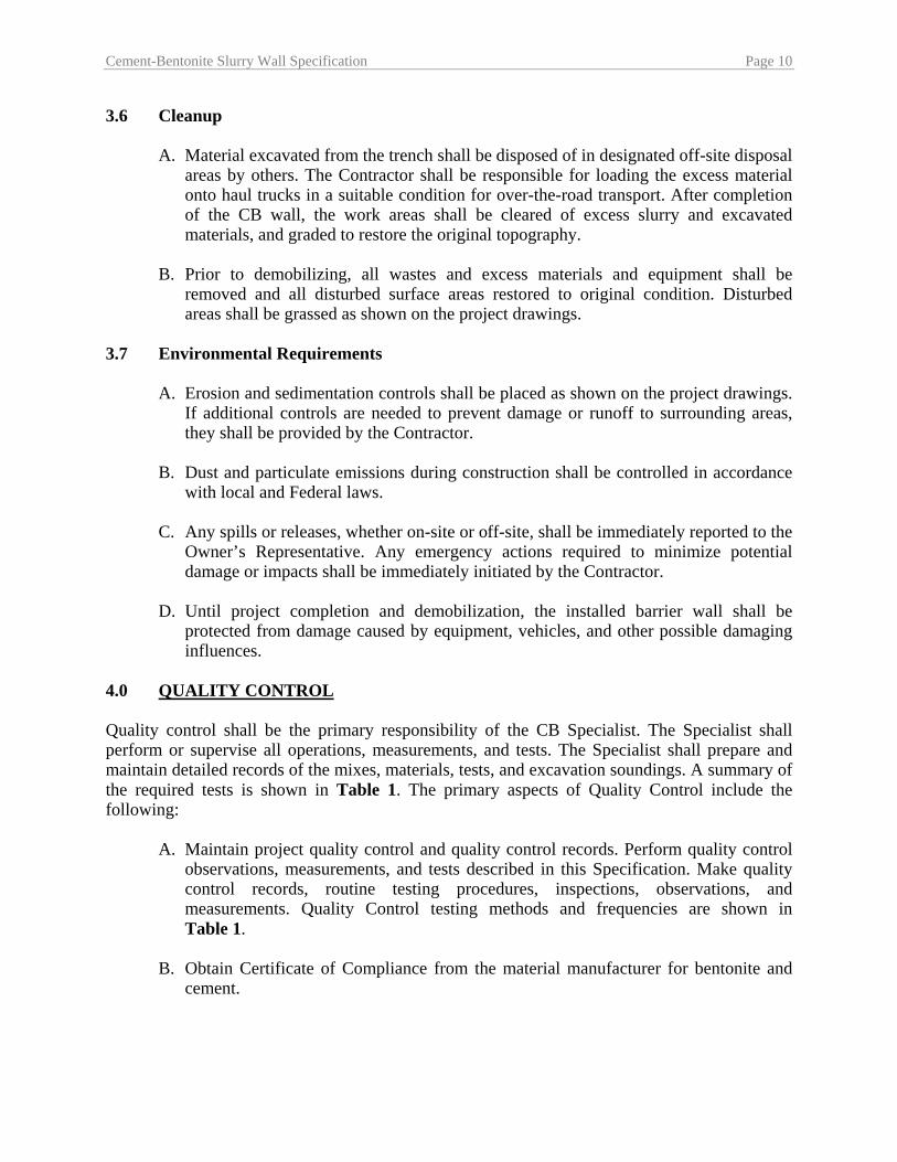
4.0 QUALITY CONTROL Quality control shall be the primary responsibility of the CB Specialist. The Specialist shall perform or supervise all operations, measurements, and tests. The Specialist shall prepare and maintain detailed records of the mixes, materials, tests, and excavation soundings. A summary of the required tests is shown in Table 1. The primary aspects of Quality Control include the following:
A. Maintain project quality control and quality control records. Perform quality control observations, measurements, and tests described in this Specification. Make quality control records, routine testing procedures, inspections, observations, and measurements. Quality Control testing methods and frequencies are shown in Table 1.
B. Obtain Certificate of Compliance from the material manufacturer for bentonite and
cement.
Cement-Bentonite Slurry Wall Specification Page 11
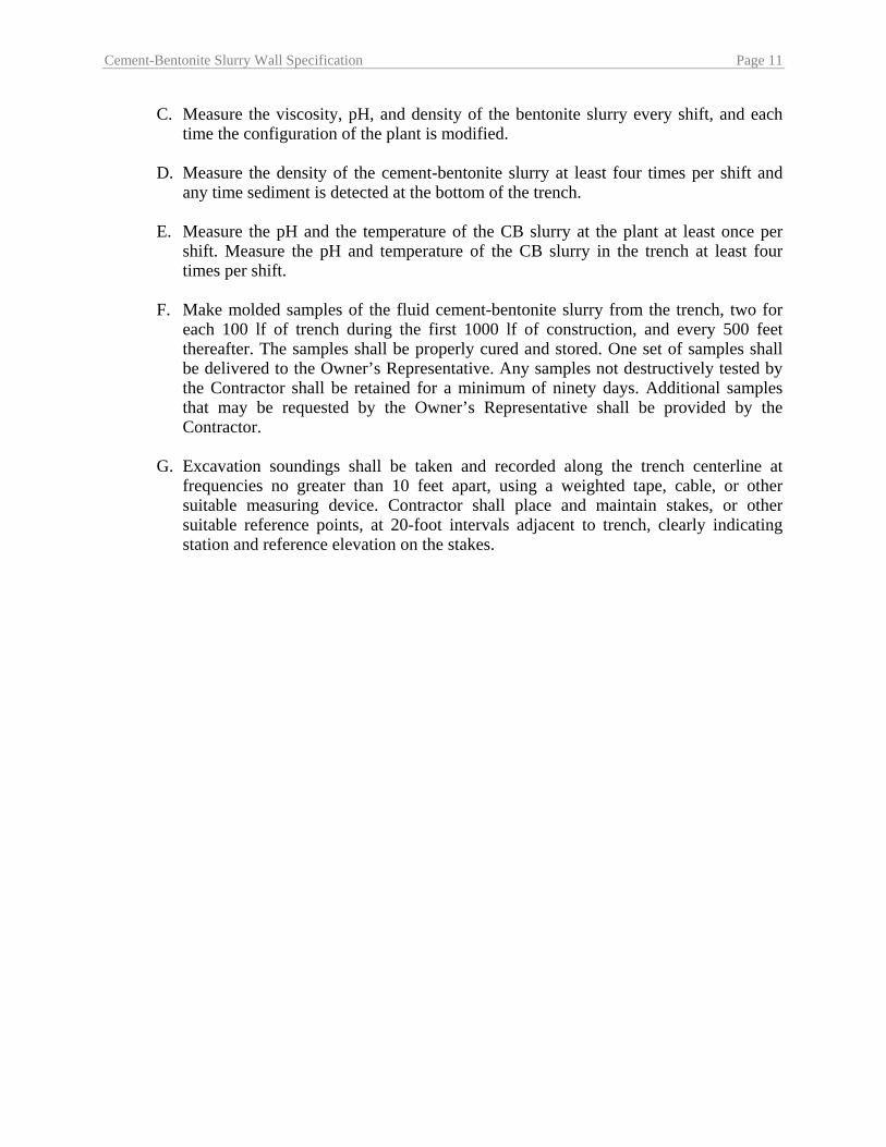
C. Measure the viscosity, pH, and density of the bentonite slurry every shift, and each time the configuration of the plant is modified.
D. Measure the density of the cement-bentonite slurry at least four times per shift and
any time sediment is detected at the bottom of the trench.
E. Measure the pH and the temperature of the CB slurry at the plant at least once per shift. Measure the pH and temperature of the CB slurry in the trench at least four times per shift.
F. Make molded samples of the fluid cement-bentonite slurry from the trench, two for
each 100 lf of trench during the first 1000 lf of construction, and every 500 feet thereafter. The samples shall be properly cured and stored. One set of samples shall be delivered to the Owner’s Representative. Any samples not destructively tested by the Contractor shall be retained for a minimum of ninety days. Additional samples that may be requested by the Owner’s Representative shall be provided by the Contractor.
G. Excavation soundings shall be taken and recorded along the trench centerline at
frequencies no greater than 10 feet apart, using a weighted tape, cable, or other suitable measuring device. Contractor shall place and maintain stakes, or other suitable reference points, at 20-foot intervals adjacent to trench, clearly indicating station and reference elevation on the stakes.

Cement-Bentonite Slurry Wall Specification Page 12
H. Records – Contractor shall maintain records of testing, measurements, and inspections performed to ascertain that the CB barrier wall construction meets the requirements of the Plans and Specifications. Contractor shall furnish reports, records, and documentation to Owner’s Representative on a weekly basis during construction. Contractor shall maintain the following records:
• As-built profile of the trench bottom, including descriptions of typical materials encountered in the excavation, as determined from soundings.
• Results of construction control testing required by this Specification, including water tests, slurry tests, strength, and permeability tests. Records of observations, measurements, and tests shall be identified by Station No.
• Bentonite slurry and cement-bentonite grout mix quantities, and proportions of additives utilized, if any. Report any adjustments made to slurry mixes.
• Construction log of daily activities including delays encountered during construction, causes of delays, locations of affected areas, and extent of delays. Record unusual conditions or problems encountered and the dispositions made.
Cement-Bentonite Slurry Wall Specification Page 13
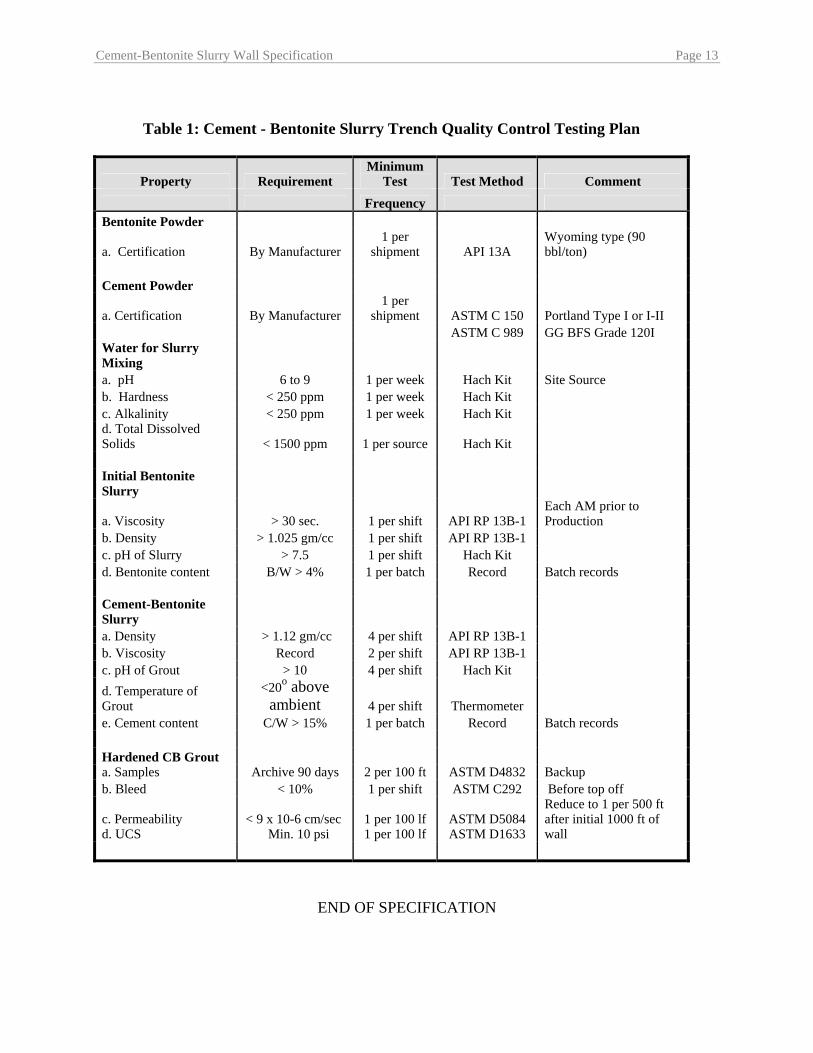
Table 1: Cement - Bentonite Slurry Trench Quality Control Testing Plan
Property Requirement Minimum
Test Test Method Comment
Frequency Bentonite Powder
a. Certification By Manufacturer 1 per
shipment API 13A Wyoming type (90 bbl/ton)
Cement Powder
a. Certification By Manufacturer 1 per
shipment ASTM C 150 Portland Type I or I-II ASTM C 989 GG BFS Grade 120I Water for Slurry Mixing a. pH 6 to 9 1 per week Hach Kit Site Source b. Hardness < 250 ppm 1 per week Hach Kit c. Alkalinity < 250 ppm 1 per week Hach Kit d. Total Dissolved Solids < 1500 ppm 1 per source Hach Kit
Initial Bentonite Slurry
a. Viscosity > 30 sec. 1 per shift API RP 13B-1 Each AM prior to Production
b. Density > 1.025 gm/cc 1 per shift API RP 13B-1 c. pH of Slurry > 7.5 1 per shift Hach Kit d. Bentonite content B/W > 4% 1 per batch Record Batch records Cement-Bentonite Slurry a. Density > 1.12 gm/cc 4 per shift API RP 13B-1 b. Viscosity Record 2 per shift API RP 13B-1 c. pH of Grout > 10 4 per shift Hach Kit d. Temperature of Grout
<20o above ambient 4 per shift Thermometer
e. Cement content C/W > 15% 1 per batch Record Batch records Hardened CB Grout a. Samples Archive 90 days 2 per 100 ft ASTM D4832 Backup b. Bleed < 10% 1 per shift ASTM C292 Before top off
c. Permeability d. UCS
< 9 x 10⁻⁶ cm/sec Min. 10 psi
1 per 100 lf 1 per 100 lf
ASTM D5084 ASTM D1633
Reduce to 1 per 500 ft after initial 1000 ft of wall
END OF SPECIFICATION

Scope of Work Construction of Phase 1Cement-Bentonite Seepage Barrier L-31N
APPENDIX C AT-750 TRENCHING MACHINE SPECIFICATIONS
October 2010
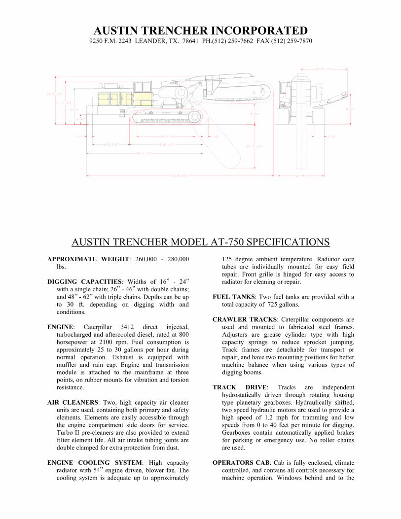
AUSTIN TRENCHER INCORPORATED 9250 F.M. 2243 LEANDER, TX. 78641 PH.(512) 259-7662 FAX (512) 259-7870
AUSTIN TRENCHER MODEL AT-750 SPECIFICATIONS
APPROXIMATE WEIGHT: 260,000 - 280,000
lbs.
DIGGING CAPACITIES: Widths of 16” - 24”
with a single chain; 26” - 46” with double chains;
and 48” - 62” with triple chains. Depths can be up
to 30 ft. depending on digging width and
conditions.
ENGINE: Caterpillar 3412 direct injected,
turbocharged and aftercooled diesel, rated at 800
horsepower at 2100 rpm. Fuel consumption is
approximately 25 to 30 gallons per hour during
normal operation. Exhaust is equipped with
muffler and rain cap. Engine and transmission
module is attached to the mainframe at three
points, on rubber mounts for vibration and torsion
resistance.
AIR CLEANERS: Two, high capacity air cleaner
units are used, containing both primary and safety
elements. Elements are easily accessible through
the engine compartment side doors for service.
Turbo II pre-cleaners are also provided to extend
filter element life. All air intake tubing joints are
double clamped for extra protection from dust.
ENGINE COOLING SYSTEM: High capacity
radiator with 54” engine driven, blower fan. The
cooling system is adequate up to approximately
125 degree ambient temperature. Radiator core
tubes are individually mounted for easy field
repair. Front grille is hinged for easy access to
radiator for cleaning or repair.
FUEL TANKS: Two fuel tanks are provided with a
total capacity of 725 gallons.
CRAWLER TRACKS: Caterpillar components are
used and mounted to fabricated steel frames.
Adjusters are grease cylinder type with high
capacity springs to reduce sprocket jumping.
Track frames are detachable for transport or
repair, and have two mounting positions for better
machine balance when using various types of
digging booms.
TRACK DRIVE: Tracks are independent
hydrostatically driven through rotating housing
type planetary gearboxes. Hydraulically shifted,
two speed hydraulic motors are used to provide a
high speed of 1.2 mph for tramming and low
speeds from 0 to 40 feet per minute for digging.
Gearboxes contain automatically applied brakes
for parking or emergency use. No roller chains
are used.
OPERATORS CAB: Cab is fully enclosed, climate
controlled, and contains all controls necessary for
machine operation. Windows behind and to the
side of the operator swing open for ventilation if
required. Cab elevates hydraulically up to 42”,
and is fully insulated for noise reduction. The
high backed operators seat has folding arm rests,
is adjustable up and down, forward and backward,
and swivels for operator comfort and increased
visibility.
COUNTERWEIGHT: Extendible counterweight is
attached to the front of the machine to maintain
stability when the boom is in the raised position.
The weight is approximately 13,000 lbs. and
hydraulically extends out 48”.
HYDRAULIC SYSTEM: Closed loop hydrostatic
transmissions operate the tracks and conveyor,
open loop gear type systems operate all other
functions. The hydraulic oil reservoir is mounted
to the side of the machine and has a capacity of
220 gallons. A side mounted oil cooler with a
hydraulically driven fan provides adequate
cooling.
CONVEYOR: A 42” width, belt conveyor with an
arched frame is used to discharge the spoil. The
conveyor frame is shiftable from side to side and
the belt is reversible. Solid, low friction slide
material is used to support the belt. No bearings
are used except on the end rollers. The frame
consists of a center section with folding
extensions on each end. Both long and short
extensions are available for various spoil
placement or overall width requirements. The
conveyor shifting mechanism automatically locks
when the desired position is reached.
BOOM HOIST: The boom is elevated by three, 12”
diameter cylinders mounted on top of the
mainframe and two, 7 1/2” diameter cylinders
mounted to the sides of the mainframe. Two hoist
speeds are provided, SLOW: for making small
grade corrections and, FAST: for positioning the
boom into or out of the ditch quickly.
DIGGING ASSEMBLY DRIVE: The digging chain
is driven mechanically through a large power shift
transmission mounted directly to the engine. The
transmission contains a torque converter which
multiplies the engine torque when the digging
chain attempts to stall. The transmission and
torque converter is cooled by two oil coolers
mounted to the side of the machine along with a
separate, hydraulically driven fan. A differential
gearbox is used for extra reduction and to divide
the power to each side of the machine. The
headshaft is driven through multiple strand roller
chains with eccentric idlers for adjustment.
Digging chain speeds are approximately 189, 347,
476, and 614 feet per minute.
DIGGING ASSEMBLY: Caterpillar type chains are
used with high strength plates bolted across them.
Tooth holders for carbide tipped teeth are welded
to these plates. These plates also contain drag bars
to help carry the excavated material out of the
trench. The digging chain is adjusted with large
grease type hydraulic cylinders mounted to each
side of the boom. The adjustment is maintained
with shims and bolts which keep the boom from
sliding in or out. The boom is fabricated of heavy
steel plate with extra weight added to increase
diggability. Replaceable, abrasive resistant wear
plates are provided on the surfaces where the
digging chain contacts the boom. The tailwheels
are 48” diameter and mounted in large spherical
roller bearings. Double seals are provided for dirt
and moisture exclusion. Extra weight can also be
added to the tailwheels if necessary.
Scope of Work Construction of Phase 1Cement-Bentonite Seepage Barrier L-31N
APPENDIX D QUALITY CONTROL/QUALITY ASSURANCE PLAN
October 2010
CONSTRUCTION QUALITY CONTROL/QUALITY ASSURANCE PLAN
The slurry wall specialty Contractor will perform the field quality control (QC) testing, and the Geotechnical Engineer will provide full time monitoring inspection during construction, and will also provide quality assurance (QA) testing services. The scope of services for the QC/QA work, described below, has been developed following recommendations published by the Portland Cement Association and the USACE. Additional testing and monitoring items, beyond what are required on typical slurry wall projects, have been included based on a comprehensive review and evaluation of the demonstration wall constructed at the site in August 2009. In particular, the Plan requires intensive probing, sampling, and testing during the initial phase of the project—defined as the first 1000 feet of wall construction. The purpose of the increased QC/QA activities is to confirm that the as-built wall has suitable composition and properties meeting the project specifications, and extends from top to bottom of trench with limited entrainment of sand and gravel particles. Contractor’s Quality Control Requirements The slurry wall Contractor will provide QC testing during design, construction, and post-construction as described in the following paragraphs. Industry standard test procedures apply to this project, and will be part of the Contractor’s QC program:
REFERENCE TITLE OR DESCRIPTION API Spec 13A Specification for Drilling-Fluid Materials API RP 13B-1 Recommended Practice Standard Procedure for Field
Testing Water-Based Drilling Fluids ASTM C 150 Standard Specification for Portland Cement ASTM D 1633 Compressive Strength of Molded Soil-Cement Cylinders ASTM D 4380 Density of Bentonite Slurries ASTM D 4832 Preparation and Testing of Controlled Low Strength
Material Test Cylinders ASTM D 5084 Measurement of Hydraulic Conductivity of Saturated
Porous Materials Using a Flexible Wall Permeameter Initial Testing The Contractor shall perform mix design testing to document that the selected mix design meets the project specifications. The tests will include a bench scale demonstration that documents satisfactory performance of the slurry in an environment that replicates conditions at the L-31N site after trenching and before slurry placement. (specifications for test include demonstration tank of appropriate size with flowing sand + water placed in bottom 25% of volume, design mix in top 75% of volume, and appropriate mixing/blending instrument). The results of this slurry dilution test will determine the maximum water content and sediment content for field placement.
Contractor will also run a Pinhole Dispersion Test (ASTM D4767) on a sample of hardened diluted design mix to demonstrate stability of the mix under high hydraulic gradient. At least two weeks prior to construction, Contractor shall submit proportions and properties of the proposed CB design mix, including cement, bentonite, additives, and water proportions; viscosity, density, unconfined compressive strength, and permeability values. Design mix and properties will be submitted to the Owner’s Representative for review and approval. Equipment The Contractor shall mobilize slurry mixing, storage, and delivery equipment of suitable capacity and manufacture to accomplish the mixing, blending, and delivery of cement bentonite slurry to the trench excavation at the rate required for construction, and with the properties required to meet the material specifications. The Contractor shall employ trench bottom preparation equipment, including air-lift system to remove loose particles or debris on the trench bottom, and provide full penetration of the cement bentonite slurry.
The Contractor shall provide field sampling and testing equipment as required to meet the Quality Control specifications. As a minimum, the equipment shall include the following: Standard Marsh funnel viscometer, Mud Balance Scale for direct reading of density, Slurry Sampler (piston or thief sampler), Sounding Tape for measuring depth to bottom of excavation, API Filter Press for filtrate loss, Standard Test Cylinders for laboratory test samples, 200 mesh Sieve for sand/gravel determination, and Water Test Kit (pH, hardness, alkalinity, dissolved solids, temperature). Slurry Placement and Blending Slurry placement will begin with excavation of the backfilled trench down to the design depth of 35 feet below land surface (or to the depth that trench was cut with trenching machine, whichever is greater), using appropriate mechanical excavation equipment. As the backfill is excavated, CB slurry will be introduced into the excavation at a rate sufficient to maintain the slurry at least 2 feet above groundwater level. An air lift system will follow as close as practical behind the excavator. The air lift will be placed with its suction intake as close as practical to the bottom of the excavation. The discharge will be at the top of the slurry, at a location and depth readily accessible for observation and sampling. The volume displaced by the air lift will be adequate to maintain the bottom of the trench free from sand and gravel sediment. CB slurry shall be maintained at all times in a condition that meets the Specifications with regard to composition, viscosity, and density. If sediment is measured or sampled at the bottom of the trench after passage of the air lift, the viscosity and density of the CB slurry will be measured and increased as necessary using additional cement and bentonite. Excavation shall cease until uniform slurry with suspended sediment is determined to exist from top to bottom of the trench. Quality Control Testing and Sampling Program Quality control shall be the responsibility of the Contractor. The quality control testing and monitoring program is designed to ensure that the CB slurry placed in the trench excavation has (a) suitable composition and properties meeting the project specifications, (b) consistent placement from top to bottom of trench, and (c) limited entrainment of sand and gravel particles. During the installation process, slurry density, viscosity, pH, temperature, and filtrate properties shall be monitored to check that the slurry meets all specified properties. These properties are designed to ensure the slurry will have the characteristics required to maintain a stable excavation and avoid dilution by sedimented backfill or groundwater. All of these slurry properties are checked using field testing equipment according to American Petroleum Institute (API) methods listed above.
The scope of QC testing is further defined in the Project Specifications. It includes testing of the bentonite slurry and water used to prepare the slurry, testing of the CB slurry at the mix plant and in the trench during construction. As the excavation proceeds, the depth of the trench shall be sounded at 10 ft intervals behind the air lift, using the weighted tape. After every 50 foot interval of wall construction, soundings shall be repeated, starting at the beginning of the 50 foot interval. All depth soundings shall be recorded and compared with subsequent soundings. If any soundings indicate sedimentation, a sample will be taken at the bottom of the trench using an appropriate thief or piston sampler. Based on the sample viscosity, water content, and composition, the Owner’s Representative will determine if the sample meets Specifications for diluted design mix. If any samples do not exhibit satisfactory slurry behavior, the Contractor will utilize the air lift and the excavator to remix and blend the slurry until satisfactory slurry composition is achieved. Additional cement and bentonite may be added to the slurry to assist in achieving compliance with the Specifications. At the Contractor’s option, air-lifted sediment may be removed from the trench to assist in achieving compliance. To determine the CB properties and composition during the initial 1000 lineal feet of slurry wall construction, both samples and test cylinders of slurry will be taken in the trench every 100 lineal feet. The test samples will be taken at three locations: the air lift discharge, mid-depth of the wall (17.5 feet below ground surface), and bottom of wall (35 feet below ground surface). Samples will be placed in test cylinders, cured and tested at an off-site laboratory for strength and permeability values, as described in the Specifications. Additional jar samples will be taken for classification testing at the site. Following the initial phase of wall construction, if the test results indicate satisfactory slurry installation in terms of consistency and depth, the sample interval will be extended to 500 feet. At any time, in the judgment of the Owner’s Representative, additional probing and sampling may be required. QUALITY ASSURANCE TESTING AND MONITORING The project Geotechnical Engineer will be responsible for the Quality Assurance (QA) testing program. The scope and schedule of testing and oversight are described in the following sections. Hand Cone Penetrometer Testing During the initial phase of slurry wall construction, hand cone penetrometer testing will be done every 100 feet along the wall. Approximately 72 hours after placement of the slurry, a penetration test will be performed using an instrumented cone penetrometer advanced by hand pushing. The penetrometer will be mounted in a centering rig spanning the width of the trench. The resistance to penetration will be measured every 1
foot below top of wall, down to refusal. Data will be recorded and the total depth of penetration compared to the depth soundings taken during installation. If the data indicate significant variations in the consistency of the wall, or in the total depth, samples will be taken using a slurry sampler. A truck-mounted Cone Penetration Test rig may also be used to assist the evaluation. An unsatisfactory evaluation, indicating failure to meet project, will require reconstruction of the wall in the failed area. Provided the wall construction during the initial phase is satisfactory, the hand cone testing during subsequent construction will be conducted at 500-foot intervals along the wall. Truck-mounted Cone Penetration Tests (CPT) Following construction of each 2500 lineal feet of wall, cone penetration tests using a truck-mounted rig will be made each 500 feet to determine the final as-built properties of the wall. These tests will be scheduled at least 30 days after installation of the wall at each test section. Based on the results of the CPT tests, additional sampling using SPT borings plus undisturbed Shelby tube sampling will be completed at selected locations, based on variations in wall construction identified by the CPT tests. Additional QA Testing During construction, an experienced geotechnical technician will be on site full-time to observe and record the progress of the work for the Owner. The technician will record depth soundings and make additional soundings as needed to confirm the data. The geotechnical technician will observe and note trench location and depth during the operation of the trenching machine, and will record the daily progress of both the trenching contractor and the slurry wall contractor. The technician will also take additional samples of representative slurry materials for independent testing to confirm physical properties such as strength, permeability, and sand/gravel content. The geotechnical technician will also perform the hand cone penetrometer tests and other probing and sampling following construction needed to confirm that Specifications are being met. The geotechnical technician will also note any environmental or safety issues that are observed, and bring them immediately to the attention of the Contractor and Owner.
Scope of Work Construction of Phase 1Cement-Bentonite Seepage Barrier L-31N
October 2010
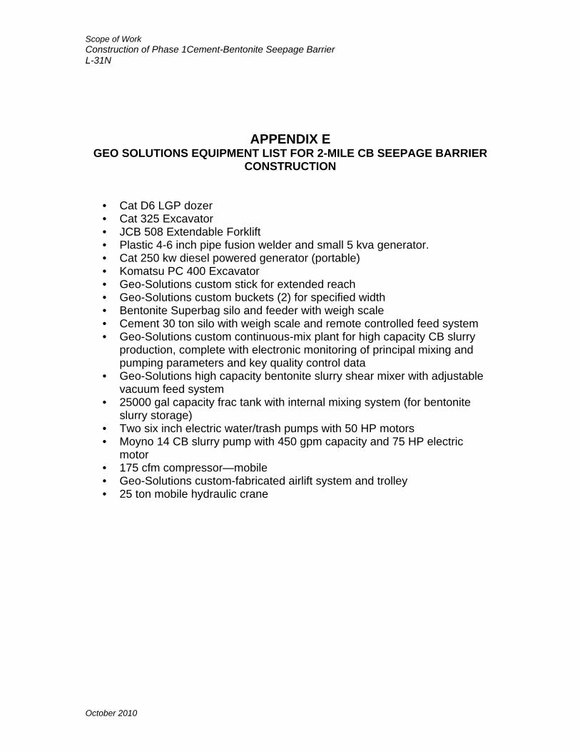
APPENDIX E GEO SOLUTIONS EQUIPMENT LIST FOR 2-MILE CB SEEPAGE BARRIER
CONSTRUCTION
• Cat D6 LGP dozer • Cat 325 Excavator • JCB 508 Extendable Forklift • Plastic 4-6 inch pipe fusion welder and small 5 kva generator. • Cat 250 kw diesel powered generator (portable) • Komatsu PC 400 Excavator • Geo-Solutions custom stick for extended reach • Geo-Solutions custom buckets (2) for specified width • Bentonite Superbag silo and feeder with weigh scale • Cement 30 ton silo with weigh scale and remote controlled feed system • Geo-Solutions custom continuous-mix plant for high capacity CB slurry
production, complete with electronic monitoring of principal mixing and pumping parameters and key quality control data
• Geo-Solutions high capacity bentonite slurry shear mixer with adjustable vacuum feed system
• 25000 gal capacity frac tank with internal mixing system (for bentonite slurry storage)
• Two six inch electric water/trash pumps with 50 HP motors • Moyno 14 CB slurry pump with 450 gpm capacity and 75 HP electric
motor • 175 cfm compressor—mobile • Geo-Solutions custom-fabricated airlift system and trolley • 25 ton mobile hydraulic crane