Embed Size (px)
Citation preview
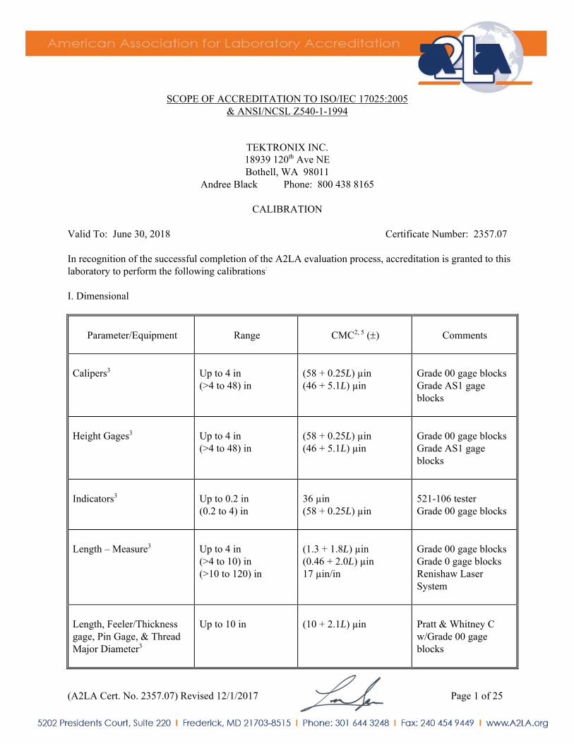
(A2LA Cert. No. 2357.07) Revised 12/1/2017 Page 1 of 25
SCOPE OF ACCREDITATION TO ISO/IEC 17025:2005 & ANSI/NCSL Z540-1-1994
TEKTRONIX INC. 18939 120th Ave NE Bothell, WA 98011
Andree Black Phone: 800 438 8165
CALIBRATION Valid To: June 30, 2018 Certificate Number: 2357.07 In recognition of the successful completion of the A2LA evaluation process, accreditation is granted to this laboratory to perform the following calibrations:
I. Dimensional
Parameter/Equipment
Range
CMC2, 5 ()
Comments
Calipers3
Up to 4 in (>4 to 48) in
(58 + 0.25L) µin (46 + 5.1L) µin
Grade 00 gage blocks Grade AS1 gage blocks
Height Gages3
Up to 4 in (>4 to 48) in
(58 + 0.25L) µin (46 + 5.1L) µin
Grade 00 gage blocks Grade AS1 gage blocks
Indicators3
Up to 0.2 in (0.2 to 4) in
36 µin (58 + 0.25L) µin
521-106 tester Grade 00 gage blocks
Length – Measure3
Up to 4 in (>4 to 10) in (>10 to 120) in
(1.3 + 1.8L) µin (0.46 + 2.0L) µin 17 µin/in
Grade 00 gage blocks Grade 0 gage blocks Renishaw Laser System
Length, Feeler/Thickness gage, Pin Gage, & Thread Major Diameter3
Up to 10 in
(10 + 2.1L) µin
Pratt & Whitney C w/Grade 00 gage blocks
(A2LA Cert. No. 2357.07) Revised 12/1/2017 Page 2 of 25
Parameter/Equipment
Range
CMC2, 5 ()
Comments
Micrometers3
Up to 4 in (>4 to 48) in
(58 + 0.25L) µin (46 + 5.1L) µin
Grade 00 gage blocks Grade AS1 gage blocks
Optical Flats3
Up to 5 in (>5 to 9) in
3.8 µin 4.6 µin
Comparison to master optical flats
Threaded Plug Pitch Diameter (4 to 80) TPI
(0.05 to 4) in
(77 + 0.3L) µin
P&W supermic with Grade 00 gage blocks with thread wires
Surface Dimensional 2D3 –
Flatness Parallelism
Up to 12 x 12 in
69 in 20 in
Surface plate, indicator
Surface Plates3 –
Repeat Flatness
Up to 96x96 in Up 157 in Diagonal Length
21 µin (6.6 + 1.95D) µin
Repeat-o-meter Leveling system
Gage Blocks
(0.01 to 1) in (1 to 4) in (4 to 12) in (12 to 20) in
(1.3 + 1.4L) µin (0.90 + 1.8L) µin (0.25 + 2.0L) µin (0.59 + 1.9L) µin
Federal comparator with gage blocks
Ring Gages
(0.05 to 4) in
(9 + 2.3L) in
P&W Lab Master™
Tape Measure, Ruler, Pi Tapes, CMM3
Up to 120 in 17 µin/in
Renishaw Laser System
(A2LA Cert. No. 2357.07) Revised 12/1/2017 Page 3 of 25
II. Electrical – DC/Low Frequency
Parameter/Range
Frequency
CMC2, 4 () Comments
AC Current – Generate3
(9 to 220) A (0.22 to 2.2) mA (2.2 to 22) mA (22 to 220) mA
(0.22 to 2.2) A (2.2 to 11) A (11 to 20.5) A Clamp-On Only (20 to 149.999) A (150 to 1025) A
(10 to 20) Hz (20 to 40) Hz 40 Hz to 1 kHz (1 to 5) kHz (5 to 10) kHz (10 to 20) Hz (20 to 40) Hz 40 Hz to 1 kHz (1 to 5) kHz (5 to 10) kHz (10 to 20) Hz (20 to 40) Hz 40 Hz to 1 kHz (1 to 5) kHz (5 to 10) kHz (10 to 20) Hz (20 to 40) Hz 40 Hz to 1 kHz (1 to 5) kHz (5 to 10) kHz 20 Hz to 1 kHz (1 to 5) kHz (5 to 10) kHz 40 Hz to 1 kHz (1 to 5) kHz (5 to 10) kHz (45 to 100) Hz (0.1 to 1) kHz (1 to 5) kHz (45 to 65) Hz (65 to 440) Hz (45 to 65) Hz (65 to 440) Hz
0.23 mA/A + 16 nA 0.16 mA/A + 10 nA 0.11 mA/A + 8 nA 0.27 mA/A + 12 nA 1.0 mA/A + 65 nA 0.23 mA/A + 40 nA 0.16 mA/A + 35 nA 0.11 mA/A + 35 nA 0.19 mA/A + 110 nA 1.0 mA/A + 650 nA 0.23 mA/A + 0.4 μA 0.16 mA/A + 0.35 μA 0.11 mA/A + 0.35 μA 0.19 mA/A + 0.55 μA 1.0 mA/A + 5 μA 0.23 mA/A + 4 μA 0.16 mA/A + 3.5 μA 0.11 mA/A + 2.5 μA 0.19 mA/A + 3.5 μA 1.0 mA/A + 10 μA 0.26 mA/A + 35 μA 0.39 mA/A + 80 μA 6.2 mA/A + 160 μA 0.37 mA/A + 170 μA 0.75 mA/A + 380 μA 2.8 mA/A + 750 μA 0.94 mA/A + 3.9 mA 1.2 mA/A + 3.9 mA 23 mA/A + 3.9 mA 2.8 mA/A + 8 mA 2.8 mA/A + 340 mA 8 mA/A + 8 mA 8 mA/A + 350 mA
Fluke 5720A Fluke 5720A w/ 5725A Fluke 5520A Fluke 5520A w/ coil
(A2LA Cert. No. 2357.07) Revised 12/1/2017 Page 4 of 25
Parameter/Range
Frequency
CMC2, 4 () Comments
AC Current – Measure3
(9 to 199.99) µA (0.2 to 1.9999) mA (2 to 19.999) mA (20 to 199.99) mA (0.2 to 1.9999) A (2 to 19.999) A
(1 to 10) Hz 10 Hz to 10 kHz (10 to 30) kHz (30 to 100) kHz (1 to 10) Hz 10 Hz to 10 kHz (10 to 30) kHz (30 to 100) kHz (1 to 10) Hz 10 Hz to 10 kHz (10 to 30) kHz (30 to 100) kHz (1 to 10) Hz 10 Hz to 10 kHz (10 to 30) kHz (1 to 10) Hz 10 Hz to 10 kHz (10 to 30) kHz 10 Hz to 2 kHz (2 to 10) kHz
0.58 mA/A + 20 nA 0.52 mA/A + 20 nA 0.65 mA/A + 20 nA 3.1 mA/A + 20 nA 0.42 mA/A + 0.20 µA 0.31 mA/A + 0.20 µA 0.63 mA/A + 0.20 µA 3.1 mA/A + 0.20 µA 0.41 mA/A + 2 µA 0.31 mA/A + 2 µA 0.63 mA/A + 2 µA 3.7 mA/A + 2 µA 0.41 mA/A + 20 µA 0.30 mA/A + 20 µA 0.68 mA/A + 20 µA 0.57 mA/A + 0.20 mA 0.85 mA/A + 0.20 mA 2.4 mA/A + 0.20 mA 0.74 mA/A + 2 mA 2.1 mA/A + 2 mA
Fluke 8508A, opt 01
AC Voltage – Generate3
(0.2 to 2.2) mV
(10 to 20) Hz (20 to 40) Hz 40 Hz to 20 kHz (20 to 50) kHz (50 to 100) kHz (100 to 300) kHz (300 to 500) kHz (0.5 to 1) MHz
0.19 mV/V + 4 μV 70 μV/V + 4 μV 62 μV/V + 4 μV 0.16 mV/V + 4 μV 0.39 mV/V + 5 μV 0.81 mV/V + 10 μV 1.1 mV/V + 20 μV 2.1 mV/V + 20 μV
Fluke 5720A
(A2LA Cert. No. 2357.07) Revised 12/1/2017 Page 5 of 25
Parameter/Range
Frequency
CMC2, 4 () Comments
AC Voltage – Generate3 (cont)
(2.2 to 22) mV (22 to 220) mV
(0.22 to 2.2) V (2.2 to 22) V
(22 to 220) V
(10 to 20) Hz (20 to 40) Hz 40 Hz to 20 kHz (20 to 50) kHz (50 to 100) kHz (100 to 300) kHz (300 to 500) kHz (0.5 to 1) MHz (10 to 20) Hz (20 to 40) Hz 40 Hz to 20 kHz (20 to 50) kHz (50 to 100) kHz (100 to 300) kHz (300 to 500) kHz (0.5 to 1) MHz (10 to 20) Hz (20 to 40) Hz 40 Hz to 20 kHz (20 to 50) kHz (50 to 100) kHz (100 to 300) kHz (300 to 500) kHz (0.5 to 1) MHz (10 to 20) Hz (20 to 40) Hz 40 Hz to 20 kHz (20 to 50) kHz (50 to 100) kHz (100 to 300) kHz (300 to 500) kHz (0.5 to 1) MHz (10 to 20) Hz (20 to 40) Hz 40 Hz to 20 kHz (20 to 50) kHz (50 to 100) kHz (100 to 300) kHz (300 to 500) kHz (0.5 to 1) MHz
0.19 mV/V + 4μV 70 μV/V + 4 μV 62 μV/V + 4 μV 0.16 mV/V + 4 μV 0.39 mV/V + 5 μV 0.81 mV/V + 10 μV 1.1 mV/V + 20 μV 2.1 mV/V + 20 μV 0.19 mV/V + 12 μV 70 μV/V + 7 μV 63 μV/V+ 7 μV 0.16 mV/V + 7 μV 0.39 mV/V +17 μV 0.81 mV/V + 20 μV 1.1 mV/V + 25 μV 2.1 mV/V + 45 μV 0.19 mV/V + 40μV 81 μV/V + 15 μV 70 μV/V + 8 μV 0.16 mV/V + 10 μV 0.36 mV/V + 30 μV 0.70 mV/V + 80 μV 1.1 mV/V + 200 μV 2.1 mV/V + 300 μV 0.21 mV/V + 400 μV 83 μV/V + 150 μV 56 μV/V + 50 μV 65 μV/V + 100 μV 91 μV/V + 200 μV 0.33 mV/V + 600 μV 0.78 mV/V + 2000 μV 1.2 mV/V + 3200 μV 0.21 mV/V + 4.0 mV 89 μV/V + 1.5 mV 54 μV/V+ 0.6 mV 69 μV/V+ 1.0 mV 0.12 mV/V + 2.5 mV 0.70 mV/V + 18 mV 3.4 mV/V + 40 mV 6.2 mV/V + 80 mV
Fluke 5720A Fluke 5720A w/ 5725A
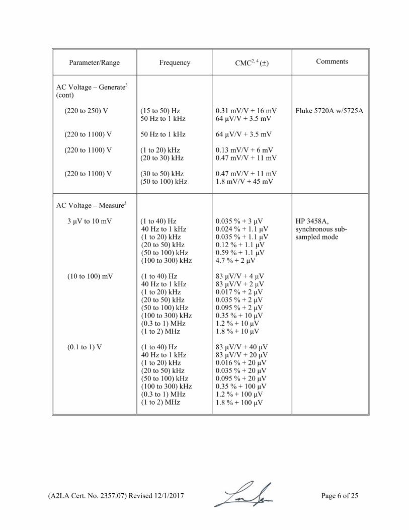
(A2LA Cert. No. 2357.07) Revised 12/1/2017 Page 6 of 25
Parameter/Range
Frequency
CMC2, 4 () Comments
AC Voltage – Generate3 (cont)
(220 to 250) V (220 to 1100) V (220 to 1100) V (220 to 1100) V
(15 to 50) Hz 50 Hz to 1 kHz 50 Hz to 1 kHz (1 to 20) kHz (20 to 30) kHz (30 to 50) kHz (50 to 100) kHz
0.31 mV/V + 16 mV 64 μV/V + 3.5 mV 64 µV/V + 3.5 mV 0.13 mV/V + 6 mV 0.47 mV/V + 11 mV 0.47 mV/V + 11 mV 1.8 mV/V + 45 mV
Fluke 5720A w/5725A
AC Voltage – Measure3
3 μV to 10 mV (10 to 100) mV (0.1 to 1) V
(1 to 40) Hz 40 Hz to 1 kHz (1 to 20) kHz (20 to 50) kHz (50 to 100) kHz (100 to 300) kHz (1 to 40) Hz 40 Hz to 1 kHz (1 to 20) kHz (20 to 50) kHz (50 to 100) kHz (100 to 300) kHz (0.3 to 1) MHz (1 to 2) MHz (1 to 40) Hz 40 Hz to 1 kHz (1 to 20) kHz (20 to 50) kHz (50 to 100) kHz (100 to 300) kHz (0.3 to 1) MHz (1 to 2) MHz
0.035 % + 3 μV 0.024 % + 1.1 μV 0.035 % + 1.1 μV 0.12 % + 1.1 μV 0.59 % + 1.1 μV 4.7 % + 2 μV 83 μV/V + 4 μV 83 μV/V + 2 μV 0.017 % + 2 μV 0.035 % + 2 μV 0.095 % + 2 μV 0.35 % + 10 μV 1.2 % + 10 μV 1.8 % + 10 μV 83 μV/V + 40 μV 83 μV/V + 20 μV 0.016 % + 20 μV 0.035 % + 20 μV 0.095 % + 20 μV 0.35 % + 100 μV 1.2 % + 100 μV 1.8 % + 100 μV
HP 3458A, synchronous sub-sampled mode
(A2LA Cert. No. 2357.07) Revised 12/1/2017 Page 7 of 25
Parameter/Range
Frequency CMC2, 4 () Comments
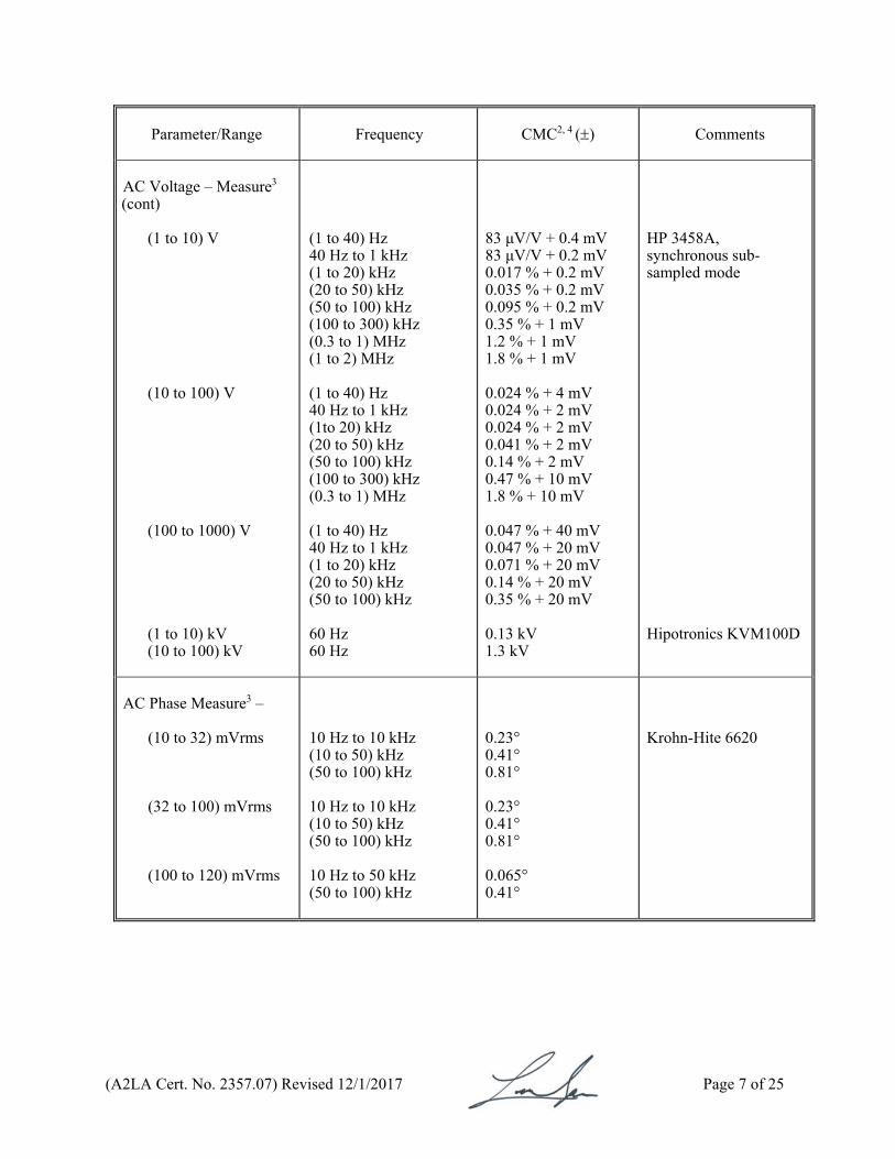
AC Voltage – Measure3 (cont)
(1 to 10) V (10 to 100) V (100 to 1000) V
(1 to 10) kV (10 to 100) kV
(1 to 40) Hz 40 Hz to 1 kHz (1 to 20) kHz (20 to 50) kHz (50 to 100) kHz (100 to 300) kHz (0.3 to 1) MHz (1 to 2) MHz (1 to 40) Hz 40 Hz to 1 kHz (1to 20) kHz (20 to 50) kHz (50 to 100) kHz (100 to 300) kHz (0.3 to 1) MHz (1 to 40) Hz 40 Hz to 1 kHz (1 to 20) kHz (20 to 50) kHz (50 to 100) kHz 60 Hz 60 Hz
83 μV/V + 0.4 mV 83 μV/V + 0.2 mV 0.017 % + 0.2 mV 0.035 % + 0.2 mV 0.095 % + 0.2 mV 0.35 % + 1 mV 1.2 % + 1 mV 1.8 % + 1 mV 0.024 % + 4 mV 0.024 % + 2 mV 0.024 % + 2 mV 0.041 % + 2 mV 0.14 % + 2 mV 0.47 % + 10 mV 1.8 % + 10 mV 0.047 % + 40 mV 0.047 % + 20 mV 0.071 % + 20 mV 0.14 % + 20 mV 0.35 % + 20 mV 0.13 kV 1.3 kV
HP 3458A, synchronous sub-sampled mode
Hipotronics KVM100D
AC Phase Measure3 –
(10 to 32) mVrms (32 to 100) mVrms (100 to 120) mVrms
10 Hz to 10 kHz (10 to 50) kHz (50 to 100) kHz 10 Hz to 10 kHz (10 to 50) kHz (50 to 100) kHz 10 Hz to 50 kHz (50 to 100) kHz
0.23° 0.41° 0.81° 0.23° 0.41° 0.81° 0.065° 0.41°
Krohn-Hite 6620
(A2LA Cert. No. 2357.07) Revised 12/1/2017 Page 8 of 25
Parameter/Range
Frequency
CMC2, 4 () Comments
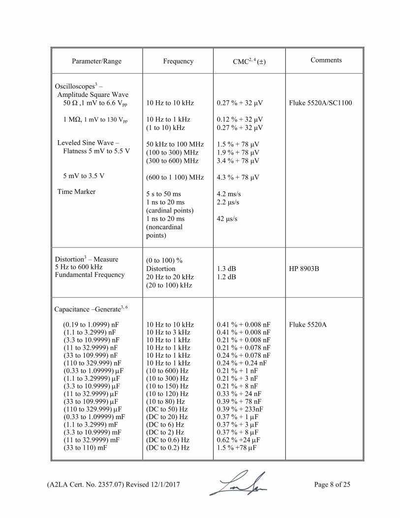
Oscilloscopes3 – Amplitude Square Wave
50 Ω ,1 mV to 6.6 Vpp 1 MΩ, 1 mV to 130 Vpp
Leveled Sine Wave –
Flatness 5 mV to 5.5 V
5 mV to 3.5 V Time Marker
10 Hz to 10 kHz 10 Hz to 1 kHz (1 to 10) kHz 50 kHz to 100 MHz (100 to 300) MHz (300 to 600) MHz (600 to 1 100) MHz 5 s to 50 ms 1 ns to 20 ms (cardinal points) 1 ns to 20 ms (noncardinal points)
0.27 % + 32 μV 0.12 % + 32 μV 0.27 % + 32 μV 1.5 % + 78 μV 1.9 % + 78 μV 3.4 % + 78 μV 4.3 % + 78 μV 4.2 ms/s 2.2 μs/s 42 μs/s
Fluke 5520A/SC1100
Distortion3 – Measure 5 Hz to 600 kHz Fundamental Frequency
(0 to 100) % Distortion 20 Hz to 20 kHz (20 to 100) kHz
1.3 dB 1.2 dB
HP 8903B
Capacitance –Generate3, 6
(0.19 to 1.0999) nF (1.1 to 3.2999) nF (3.3 to 10.9999) nF (11 to 32.9999) nF (33 to 109.999) nF (110 to 329.999) nF (0.33 to 1.09999) F (1.1 to 3.29999) F (3.3 to 10.9999) F (11 to 32.9999) F (33 to 109.999) F (110 to 329.999) F (0.33 to 1.09999) mF (1.1 to 3.2999) mF (3.3 to 10.9999) mF (11 to 32.9999) mF (33 to 110) mF
10 Hz to 10 kHz 10 Hz to 3 kHz 10 Hz to 1 kHz 10 Hz to 1 kHz 10 Hz to 1 kHz 10 Hz to 1 kHz (10 to 600) Hz (10 to 300) Hz (10 to 150) Hz (10 to 120) Hz (10 to 80) Hz (DC to 50) Hz (DC to 20) Hz (DC to 6) Hz (DC to 2) Hz (DC to 0.6) Hz (DC to 0.2) Hz
0.41 % + 0.008 nF 0.41 % + 0.008 nF 0.21 % + 0.008 nF 0.21 % + 0.078 nF 0.24 % + 0.078 nF 0.24 % + 0.24 nF 0.21 % + 1 nF 0.21 % + 3 nF 0.21 % + 8 nF 0.33 % + 24 nF 0.39 % + 78 nF 0.39 % + 233nF 0.37 % + 1 F 0.37 % + 3 F 0.37 % + 8 F 0.62 % +24 F 1.5 % +78 F
Fluke 5520A
(A2LA Cert. No. 2357.07) Revised 12/1/2017 Page 9 of 25
Parameter/Equipment
Range
CMC2, 4 () Comments
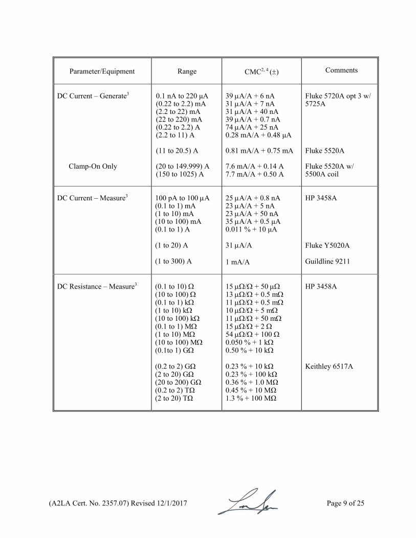
DC Current – Generate3
Clamp-On Only
0.1 nA to 220 μA (0.22 to 2.2) mA (2.2 to 22) mA (22 to 220) mA (0.22 to 2.2) A (2.2 to 11) A (11 to 20.5) A (20 to 149.999) A (150 to 1025) A
39 A/A + 6 nA 31 A/A + 7 nA 31 A/A + 40 nA 39 A/A + 0.7 nA 74 A/A + 25 nA 0.28 mA/A + 0.48 μA 0.81 mA/A + 0.75 mA 7.6 mA/A + 0.14 A 7.7 mA/A + 0.50 A
Fluke 5720A opt 3 w/ 5725A Fluke 5520A Fluke 5520A w/ 5500A coil
DC Current – Measure3
100 pA to 100 A (0.1 to 1) mA (1 to 10) mA (10 to 100) mA (0.1 to 1) A (1 to 20) A (1 to 300) A
25 A/A + 0.8 nA 23 A/A + 5 nA 23 A/A + 50 nA 35 A/A + 0.5 μA 0.011 % + 10 μA 31 A/A 1 mA/A
HP 3458A Fluke Y5020A Guildline 9211
DC Resistance – Measure3
(0.1 to 10) (10 to 100) (0.1 to 1) k (1 to 10) k (10 to 100) k (0.1 to 1) M (1 to 10) M (10 to 100) M (0.1 to 1) G (0.2 to 2) GΩ (2 to 20) GΩ (20 to 200) GΩ (0.2 to 2) TΩ (2 to 20) TΩ
15 / + 50 13 / + 0.5 m 11 / + 0.5 m 10 / + 5 m 11 / + 50 m 15 / + 2 54 / + 100 0.050 % + 1 k 0.50 % + 10 k 0.23 % + 10 kΩ 0.23 % + 100 kΩ 0.36 % + 1.0 MΩ 0.45 % + 10 MΩ 1.3 % + 100 MΩ
HP 3458A Keithley 6517A
(A2LA Cert. No. 2357.07) Revised 12/1/2017 Page 10 of 25
Parameter/Equipment
Range
CMC2, 4 () Comments
DC Resistance – Generate3
(0 to 10.9999) (11 to 32.9999) (33 to 109.9999) (110 to 329.9999) (330 to 1099.999) (1.1 to 3.299999) k (3.3 to 10.99999) k (11 to 32.99999) k (33 to 109.9999) k (110 to 329.9999) k (330 to 1099.999) k (1.1 to 3.299999) M (3.3 to 10.99999) M (11 to 32.99999) M (33 to 109.9999) M (110 to 329.9999) M (330 to 1099.999) M
37 / + 0.78 m 27 / + 1.2 m 23 / + 1.1 m 29 / + 1.6 m 23 / + 1.6 m 26 / + 20 m 25 / + 20 m 26 / + 0.16 28 / + 0.16 32 / + 1.6 28 / + 1.6 49 / + 30 0.010 % + 40 0.065 % + 1.9 k 0.041 % + 2.3 k 0.23 % + 78 k 1.2 % + 0.39 M
Fluke 5520A
DC Resistance – Generate3 Fixed Points
1 1.9 10 19 100 190 1 k 1.9 k 10 k 19 k 100 k 190 k 1 M 1.9 M 10 M 19 M 100 M
0.13 m 0.18 m 0.28 m 0.53 m 1.6 m 3.1 m 12 m 23 m 0.11 0.21 1.3 3.0 50 60 4 k 4.9 k 26 k
Fluke 5720A
DC Voltage – Measure3
Up to 200 mV 200 mV to 2 V (2 to 20) V (20 to 200) V (200 to 1050)V
6.0 µV/V + 0.10 µV 3.6 µV/V + 0.40 µV 3.6 µV/V + 4.0 µV 5.5 µV/V + 40 µV 5.5 µV/V + 0.53 mV
Fluke 8508A, opt 01
(A2LA Cert. No. 2357.07) Revised 12/1/2017 Page 11 of 25
Parameter/Equipment
Range
CMC2, 4 () Comments
DC Voltage – Measure3 (cont)
(1 to 10) kV (10 to 100) kV
59 V 590 V
Hipotronics KVM100D
DC Voltage – Generate3
(0 to 220) mV 220 mV to 2.2 V (2.2 to 11) V (11 to 22) V (22 to 220) V 220 V to 1.1 kV 1.018 V 1 V 10 V
8.5 μV/V + 0.4 μV 4.9 μV/V + 0.7 μV 3.3 μV/V + 2.5 μV 3.3 μV/V + 4 μV 4.9 μV/V + 40 μV 6.6 μV/V + 400 μV 9.5 μV 9.3 μV 16 μV
Fluke 5720A Fluke 732B
Electrical Calibration of Thermocouple Indicators3 –
Type B Type C Type E
(600 to 800) °C (800 to 1000) °C (1000 to 1550) °C (1550 to 1820) °C (0 to 150) °C (150 to 650) °C (650 to 1000) °C (1000 to 1800) °C (1800 to 2316) °C (-250 to -100) °C (-100 to -25) °C (-25 to 350) °C (350 to 650) °C (650 to 1000) °C
0.46 °C 0.36 °C 0.33 °C 0.35 °C 0.33 °C 0.29 °C 0.33 °C 0.51 °C 0.85 °C 0.52 °C 0.19 °C 0.17 °C 0.19 °C 0.24 °C
Fluke 5520A
(A2LA Cert. No. 2357.07) Revised 12/1/2017 Page 12 of 25
Parameter/Equipment
Range CMC2 () Comments
Electrical Calibration of Thermocouple Indicators – (cont)
Type J
Type K Type N Type R
Type S Type T Type U
(-210 to -100) °C (-100 to -30) °C (-30 to 150) °C (150 to 760) °C (760 to 1200) °C (-200 to -100) °C (-100 to -25) °C (-25 to 120) °C (120 to 1000) °C (1000 to 1372) °C (-200 to -100) °C (-100 to -25) °C (-25 to 120) °C (120 to 410) °C (410 to 1300) °C (0 to 250) °C (250 to 400) °C (400 to 1000) °C (1000 to 1767) °C (0 to 250) °C (250 to 1 000) °C (1000 to 1400) °C (1400 to 1767) °C (-250 to -150) °C (-150 to 0) °C (0 to 120) °C (120 to 400) °C (-200 to 0) °C (0 to 600) °C
0.32 °C 0.20 °C 0.18 °C 0.21 °C 0.26 °C 0.35 °C 0.23 °C 0.21 °C 0.31 °C 0.42 °C 0.42 °C 0.26 °C 0.24 °C 0.22 °C 0.29 °C 0.58 °C 0.37 °C 0.36 °C 0.43 °C 0.50 °C 0.39 °C 0.41 °C 0.48 °C 0.65 °C 0.27 °C 0.23 °C 0.17 °C 0.58 °C 0.29 °C
Fluke 5520A
(A2LA Cert. No. 2357.07) Revised 12/1/2017 Page 13 of 25
Parameter/Equipment
Range
CMC2 () Comments
Electrical Calibration of RTDs3 –
Pt 385, 100
Pt 3926, 100 Pt 3916, 100 Pt 385, 200 Pt 385, 500
(-200 to -80) C (-80 to 0) C (0 to 100) C (100 to 300) C (300 to 400) C (400 to 630) C (630 to 800) C (-200 to -80) C (-80 to 0) C (0 to 100) C (100 to 300) C (300 to 400) C (400 to 630) C (-200 to -190) C (-190 to -80) C (-80 to 0) C (0 to 100) C (100 to 260) C (260 to 300) C (300 to 400) C (400 to 600) C (600 to 630) C (-200 to -80) C (-80 to 0) C (0 to 100) C (100 to 260) C (260 to 300) C (300 to 400) C (400 to 600) C (600 to 630) C (-200 to -80) C (-80 to 0) C (0 to 100) C (100 to 260) C (260 to 300) C (300 to 400) C (400 to 600) C (600 to 630) C
0.06 C 0.06 C 0.08 C 0.10 C 0.10 C 0.12 C 0.23 C 0.05 C 0.06 C 0.07 C 0.09 C 0.10 C 0.13 C 0.25 C 0.05 C 0.05 C 0.06 C 0.07 C 0.08 C 0.09 C 0.11 C 0.23 C 0.05 C 0.05 C 0.05 C 0.05 C 0.12 C 0.13 C 0.14 C 0.16 C 0.05 C 0.06 C 0.06 C 0.06 C 0.08 C 0.08 C 0.09 C 0.11 C
Fluke 5520A
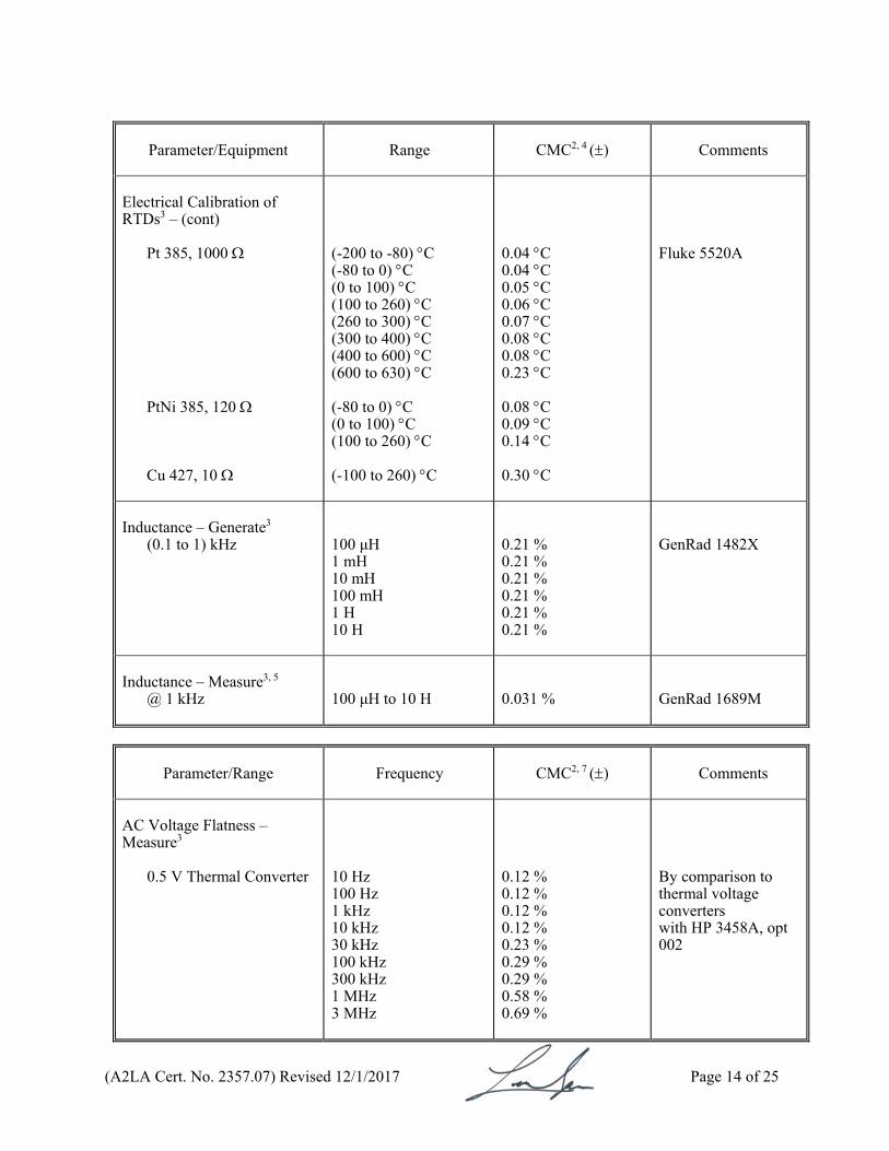
(A2LA Cert. No. 2357.07) Revised 12/1/2017 Page 14 of 25
Parameter/Equipment
Range CMC2, 4 () Comments
Electrical Calibration of RTDs3 – (cont)
Pt 385, 1000
PtNi 385, 120 Cu 427, 10
(-200 to -80) C (-80 to 0) C (0 to 100) C (100 to 260) C (260 to 300) C (300 to 400) C (400 to 600) C (600 to 630) C (-80 to 0) C (0 to 100) C (100 to 260) C (-100 to 260) C
0.04 C 0.04 C 0.05 C 0.06 C 0.07 C 0.08 C 0.08 C 0.23 C 0.08 C 0.09 C 0.14 C 0.30 C
Fluke 5520A
Inductance – Generate3
(0.1 to 1) kHz
100 μH 1 mH 10 mH 100 mH 1 H 10 H
0.21 % 0.21 % 0.21 % 0.21 % 0.21 % 0.21 %
GenRad 1482X
Inductance – Measure3, 5
@ 1 kHz
100 μH to 10 H
0.031 %
GenRad 1689M
Parameter/Range
Frequency CMC2, 7 () Comments
AC Voltage Flatness – Measure3
0.5 V Thermal Converter
10 Hz 100 Hz 1 kHz 10 kHz 30 kHz 100 kHz 300 kHz 1 MHz 3 MHz
0.12 % 0.12 % 0.12 % 0.12 % 0.23 % 0.29 % 0.29 % 0.58 % 0.69 %
By comparison to thermal voltage converters with HP 3458A, opt 002
(A2LA Cert. No. 2357.07) Revised 12/1/2017 Page 15 of 25
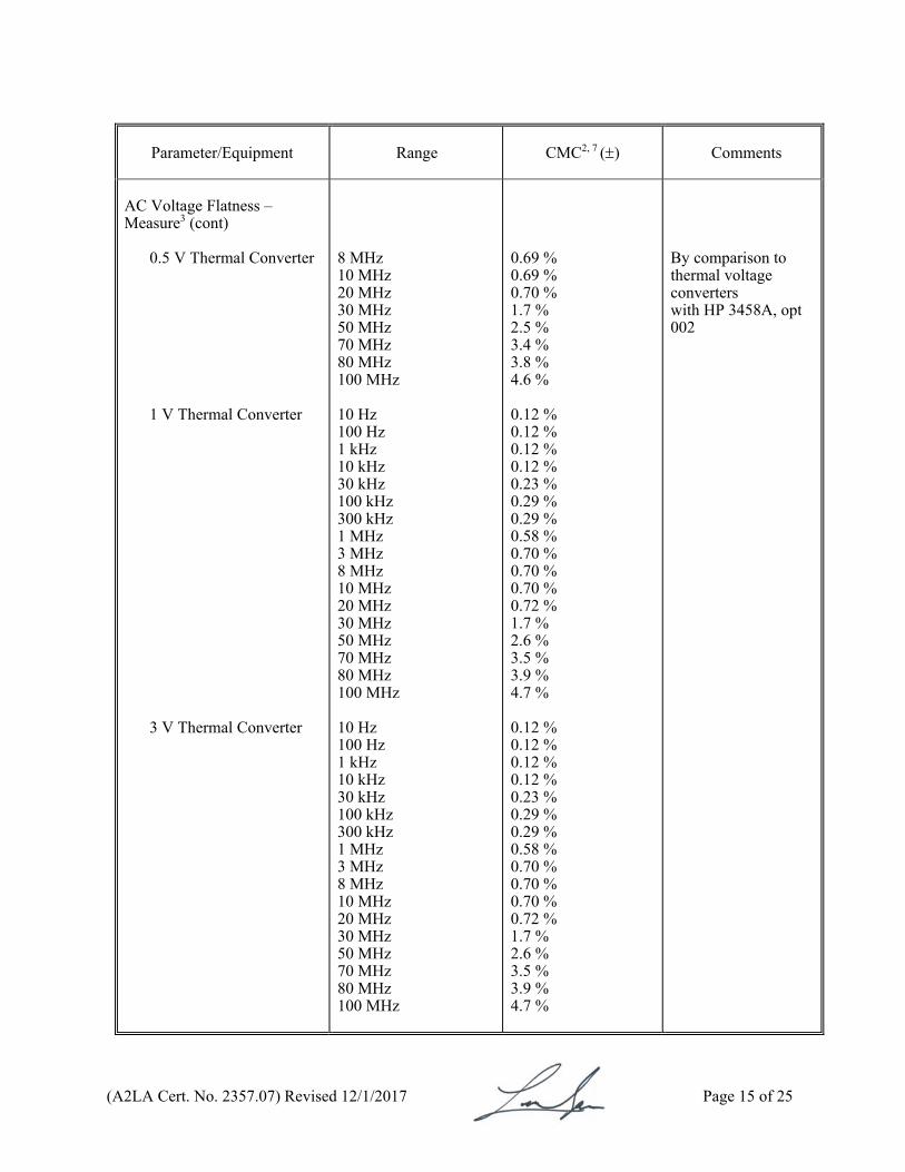
Parameter/Equipment
Range CMC2, 7 () Comments
AC Voltage Flatness – Measure3 (cont)
0.5 V Thermal Converter
1 V Thermal Converter
3 V Thermal Converter
8 MHz 10 MHz 20 MHz 30 MHz 50 MHz 70 MHz 80 MHz 100 MHz 10 Hz 100 Hz 1 kHz 10 kHz 30 kHz 100 kHz 300 kHz 1 MHz 3 MHz 8 MHz 10 MHz 20 MHz 30 MHz 50 MHz 70 MHz 80 MHz 100 MHz 10 Hz 100 Hz 1 kHz 10 kHz 30 kHz 100 kHz 300 kHz 1 MHz 3 MHz 8 MHz 10 MHz 20 MHz 30 MHz 50 MHz 70 MHz 80 MHz 100 MHz
0.69 % 0.69 % 0.70 % 1.7 % 2.5 % 3.4 % 3.8 % 4.6 % 0.12 % 0.12 % 0.12 % 0.12 % 0.23 % 0.29 % 0.29 % 0.58 % 0.70 % 0.70 % 0.70 % 0.72 % 1.7 % 2.6 % 3.5 % 3.9 % 4.7 % 0.12 % 0.12 % 0.12 % 0.12 % 0.23 % 0.29 % 0.29 % 0.58 % 0.70 % 0.70 % 0.70 % 0.72 % 1.7 % 2.6 % 3.5 % 3.9 % 4.7 %
By comparison to thermal voltage converters with HP 3458A, opt 002
(A2LA Cert. No. 2357.07) Revised 12/1/2017 Page 16 of 25
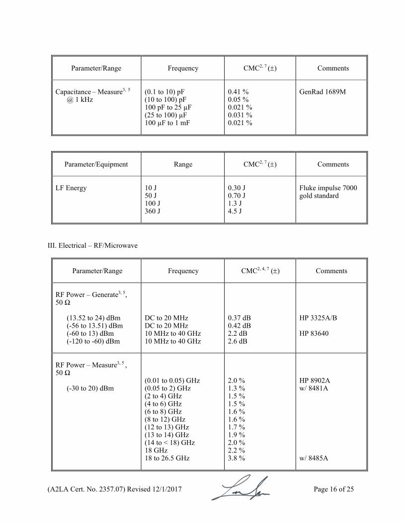
Parameter/Range
Frequency CMC2, 7 () Comments
Capacitance – Measure3, 5
@ 1 kHz
(0.1 to 10) pF (10 to 100) pF 100 pF to 25 µF (25 to 100) µF 100 µF to 1 mF
0.41 % 0.05 % 0.021 % 0.031 % 0.021 %
GenRad 1689M
Parameter/Equipment
Range CMC2, 7 () Comments
LF Energy
10 J 50 J 100 J 360 J
0.30 J 0.70 J 1.3 J 4.5 J
Fluke impulse 7000 gold standard
III. Electrical – RF/Microwave
Parameter/Range
Frequency CMC2, 4, 7 () Comments
RF Power – Generate3, 5,
50 Ω
(13.52 to 24) dBm (-56 to 13.51) dBm (-60 to 13) dBm (-120 to -60) dBm
DC to 20 MHz DC to 20 MHz 10 MHz to 40 GHz 10 MHz to 40 GHz
0.37 dB 0.42 dB 2.2 dB 2.6 dB
HP 3325A/B HP 83640
RF Power – Measure3, 5 ,
50 Ω
(-30 to 20) dBm
(0.01 to 0.05) GHz (0.05 to 2) GHz (2 to 4) GHz (4 to 6) GHz (6 to 8) GHz (8 to 12) GHz (12 to 13) GHz (13 to 14) GHz (14 to < 18) GHz 18 GHz 18 to 26.5 GHz
2.0 % 1.3 % 1.5 % 1.5 % 1.6 % 1.6 % 1.7 % 1.9 % 2.0 % 2.2 % 3.8 %
HP 8902A w/ 8481A w/ 8485A
(A2LA Cert. No. 2357.07) Revised 12/1/2017 Page 17 of 25
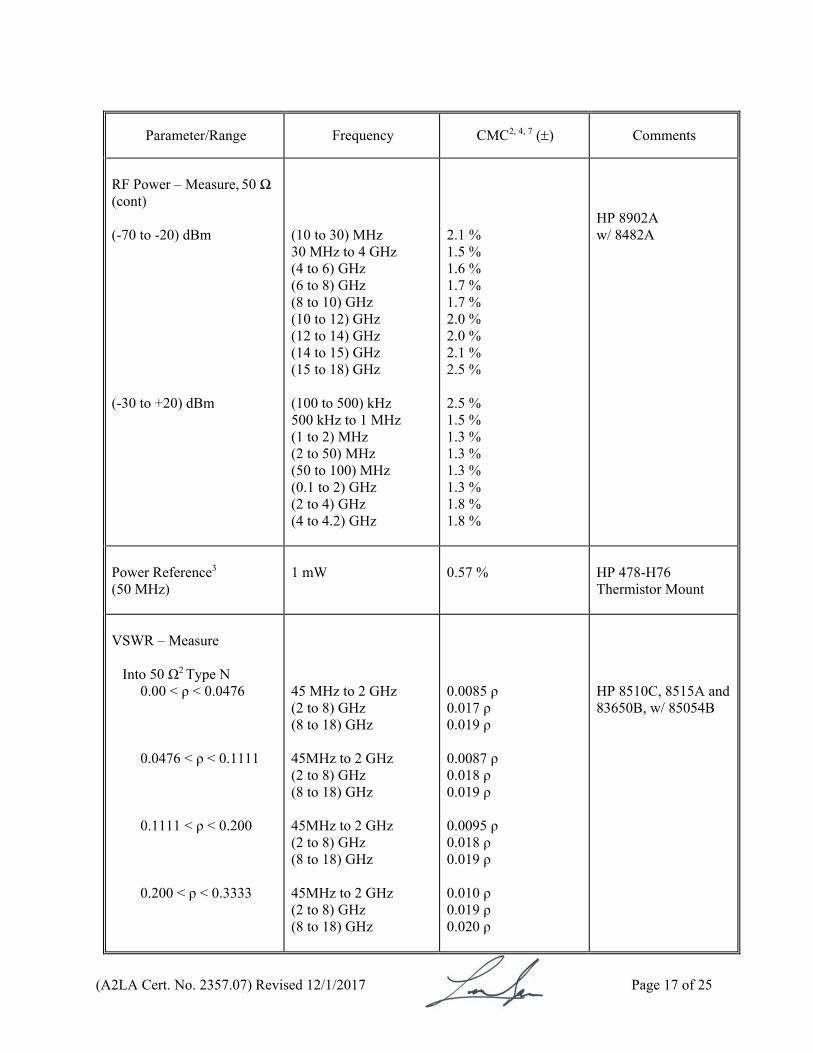
Parameter/Range
Frequency CMC2, 4, 7 () Comments
RF Power – Measure, 50 Ω (cont) (-70 to -20) dBm (-30 to +20) dBm
(10 to 30) MHz 30 MHz to 4 GHz (4 to 6) GHz (6 to 8) GHz (8 to 10) GHz (10 to 12) GHz (12 to 14) GHz (14 to 15) GHz (15 to 18) GHz (100 to 500) kHz 500 kHz to 1 MHz (1 to 2) MHz (2 to 50) MHz (50 to 100) MHz (0.1 to 2) GHz (2 to 4) GHz (4 to 4.2) GHz
2.1 % 1.5 % 1.6 % 1.7 % 1.7 % 2.0 % 2.0 % 2.1 % 2.5 % 2.5 % 1.5 % 1.3 % 1.3 % 1.3 % 1.3 % 1.8 % 1.8 %
HP 8902A w/ 8482A
Power Reference3
(50 MHz)
1 mW
0.57 %
HP 478-H76 Thermistor Mount
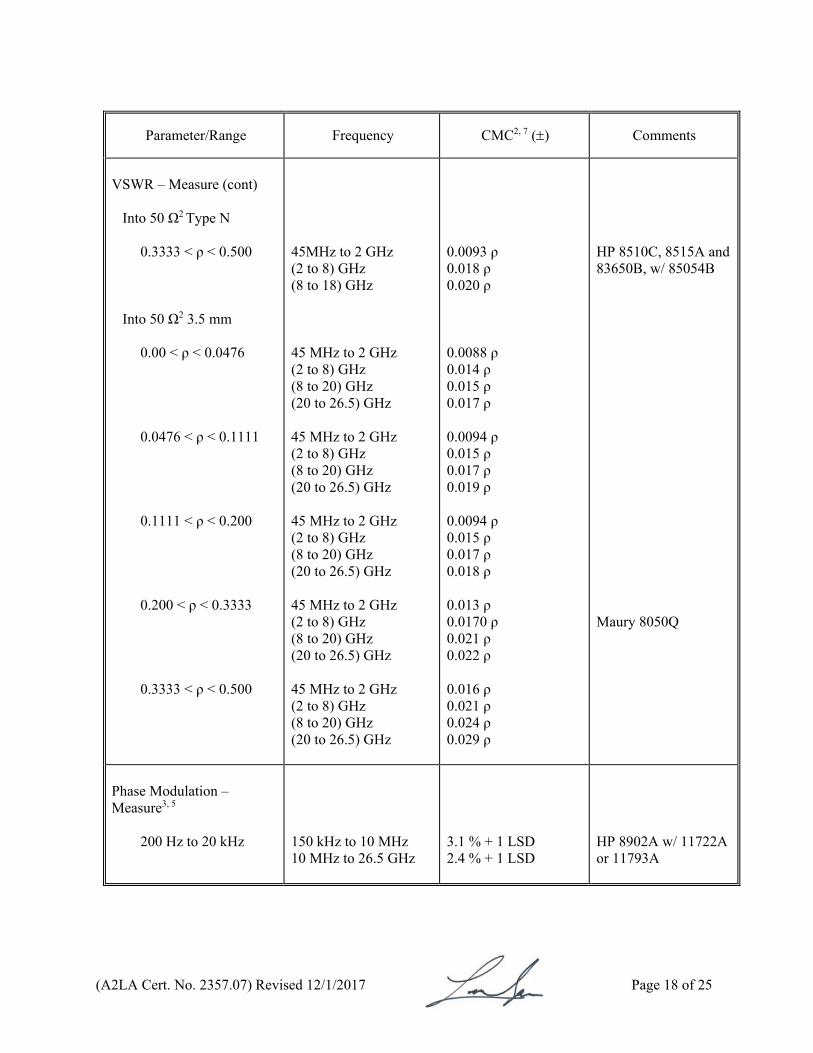
VSWR – Measure
Into 50 Ω2 Type N
0.00 < ρ < 0.0476 0.0476 < ρ < 0.1111 0.1111 < ρ < 0.200 0.200 < ρ < 0.3333
45 MHz to 2 GHz (2 to 8) GHz (8 to 18) GHz 45MHz to 2 GHz (2 to 8) GHz (8 to 18) GHz 45MHz to 2 GHz (2 to 8) GHz (8 to 18) GHz 45MHz to 2 GHz (2 to 8) GHz (8 to 18) GHz
0.0085 ρ 0.017 ρ 0.019 ρ 0.0087 ρ 0.018 ρ 0.019 ρ 0.0095 ρ 0.018 ρ 0.019 ρ 0.010 ρ 0.019 ρ 0.020 ρ
HP 8510C, 8515A and 83650B, w/ 85054B
(A2LA Cert. No. 2357.07) Revised 12/1/2017 Page 18 of 25
Parameter/Range
Frequency CMC2, 7 () Comments
VSWR – Measure (cont)
Into 50 Ω2 Type N
0.3333 < ρ < 0.500
Into 50 Ω2 3.5 mm
0.00 < ρ < 0.0476
0.0476 < ρ < 0.1111 0.1111 < ρ < 0.200 0.200 < ρ < 0.3333 0.3333 < ρ < 0.500
45MHz to 2 GHz (2 to 8) GHz (8 to 18) GHz 45 MHz to 2 GHz (2 to 8) GHz (8 to 20) GHz (20 to 26.5) GHz 45 MHz to 2 GHz (2 to 8) GHz (8 to 20) GHz (20 to 26.5) GHz 45 MHz to 2 GHz (2 to 8) GHz (8 to 20) GHz (20 to 26.5) GHz 45 MHz to 2 GHz (2 to 8) GHz (8 to 20) GHz (20 to 26.5) GHz 45 MHz to 2 GHz (2 to 8) GHz (8 to 20) GHz (20 to 26.5) GHz
0.0093 ρ 0.018 ρ 0.020 ρ 0.0088 ρ 0.014 ρ 0.015 ρ 0.017 ρ 0.0094 ρ 0.015 ρ 0.017 ρ 0.019 ρ 0.0094 ρ 0.015 ρ 0.017 ρ 0.018 ρ 0.013 ρ 0.0170 ρ 0.021 ρ 0.022 ρ 0.016 ρ 0.021 ρ 0.024 ρ 0.029 ρ
HP 8510C, 8515A and 83650B, w/ 85054B Maury 8050Q
Phase Modulation – Measure3, 5
200 Hz to 20 kHz
150 kHz to 10 MHz 10 MHz to 26.5 GHz
3.1 % + 1 LSD 2.4 % + 1 LSD
HP 8902A w/ 11722A or 11793A
(A2LA Cert. No. 2357.07) Revised 12/1/2017 Page 19 of 25
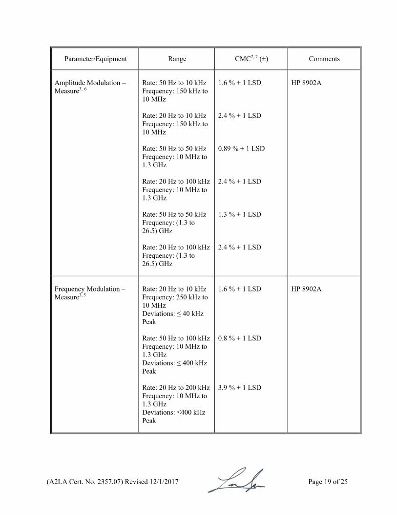
Parameter/Equipment
Range CMC2, 7 () Comments
Amplitude Modulation – Measure3, 6
Rate: 50 Hz to 10 kHz Frequency: 150 kHz to 10 MHz Rate: 20 Hz to 10 kHz Frequency: 150 kHz to 10 MHz Rate: 50 Hz to 50 kHz Frequency: 10 MHz to 1.3 GHz Rate: 20 Hz to 100 kHz Frequency: 10 MHz to 1.3 GHz Rate: 50 Hz to 50 kHz Frequency: (1.3 to 26.5) GHz Rate: 20 Hz to 100 kHz Frequency: (1.3 to 26.5) GHz
1.6 % + 1 LSD 2.4 % + 1 LSD 0.89 % + 1 LSD 2.4 % + 1 LSD 1.3 % + 1 LSD 2.4 % + 1 LSD
HP 8902A
Frequency Modulation – Measure3, 5
Rate: 20 Hz to 10 kHz Frequency: 250 kHz to 10 MHz Deviations: ≤ 40 kHz Peak Rate: 50 Hz to 100 kHz Frequency: 10 MHz to 1.3 GHz Deviations: ≤ 400 kHz Peak Rate: 20 Hz to 200 kHz Frequency: 10 MHz to 1.3 GHz Deviations: ≤400 kHz Peak
1.6 % + 1 LSD 0.8 % + 1 LSD 3.9 % + 1 LSD
HP 8902A
(A2LA Cert. No. 2357.07) Revised 12/1/2017 Page 20 of 25
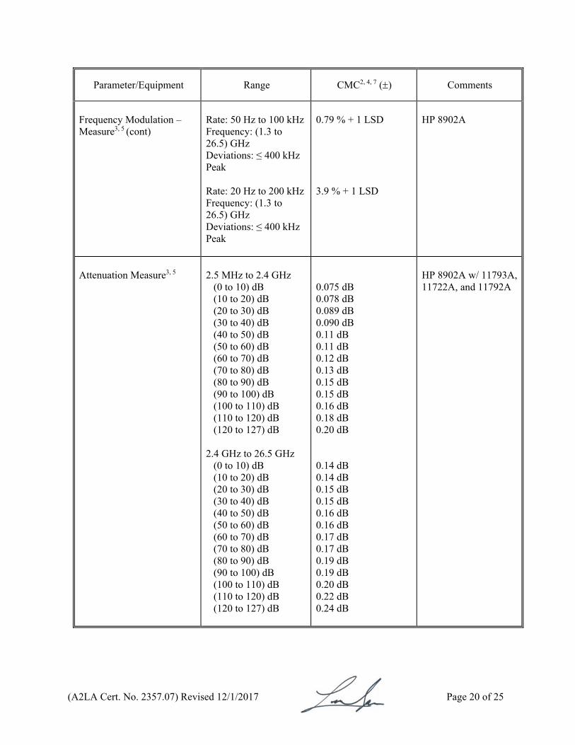
Parameter/Equipment
Range CMC2, 4, 7 () Comments
Frequency Modulation – Measure3, 5 (cont)
Rate: 50 Hz to 100 kHz Frequency: (1.3 to 26.5) GHz Deviations: ≤ 400 kHz Peak Rate: 20 Hz to 200 kHz Frequency: (1.3 to 26.5) GHz Deviations: ≤ 400 kHz Peak
0.79 % + 1 LSD 3.9 % + 1 LSD
HP 8902A
Attenuation Measure3, 5
2.5 MHz to 2.4 GHz
(0 to 10) dB (10 to 20) dB (20 to 30) dB (30 to 40) dB (40 to 50) dB (50 to 60) dB (60 to 70) dB (70 to 80) dB (80 to 90) dB (90 to 100) dB (100 to 110) dB (110 to 120) dB (120 to 127) dB
2.4 GHz to 26.5 GHz
(0 to 10) dB (10 to 20) dB (20 to 30) dB (30 to 40) dB (40 to 50) dB (50 to 60) dB (60 to 70) dB (70 to 80) dB (80 to 90) dB (90 to 100) dB (100 to 110) dB (110 to 120) dB (120 to 127) dB
0.075 dB 0.078 dB 0.089 dB 0.090 dB 0.11 dB 0.11 dB 0.12 dB 0.13 dB 0.15 dB 0.15 dB 0.16 dB 0.18 dB 0.20 dB 0.14 dB 0.14 dB 0.15 dB 0.15 dB 0.16 dB 0.16 dB 0.17 dB 0.17 dB 0.19 dB 0.19 dB 0.20 dB 0.22 dB 0.24 dB
HP 8902A w/ 11793A,11722A, and 11792A
(A2LA Cert. No. 2357.07) Revised 12/1/2017 Page 21 of 25
Parameter/Equipment
Range CMC2, 7 () Comments
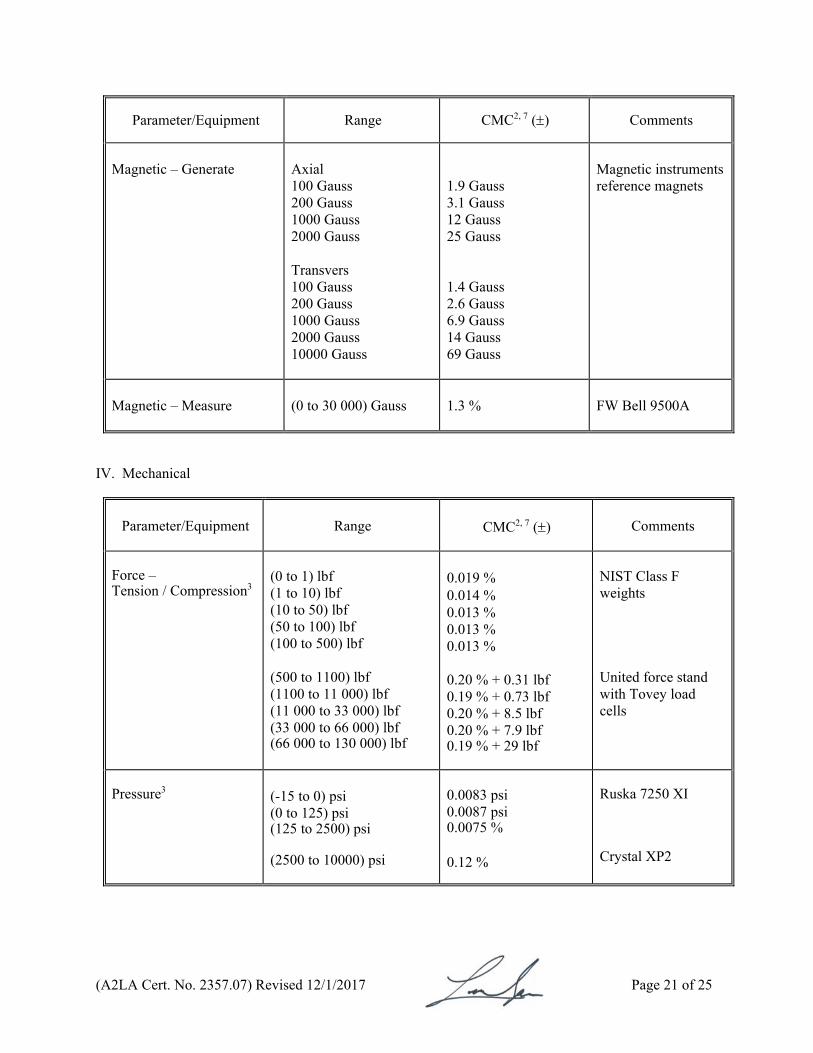
Magnetic – Generate
Axial 100 Gauss 200 Gauss 1000 Gauss 2000 Gauss Transvers 100 Gauss 200 Gauss 1000 Gauss 2000 Gauss 10000 Gauss
1.9 Gauss 3.1 Gauss 12 Gauss 25 Gauss 1.4 Gauss 2.6 Gauss 6.9 Gauss 14 Gauss 69 Gauss
Magnetic instruments reference magnets
Magnetic – Measure
(0 to 30 000) Gauss
1.3 %
FW Bell 9500A
IV. Mechanical
Parameter/Equipment
Range
CMC2, 7 ()
Comments
Force – Tension / Compression3
(0 to 1) lbf (1 to 10) lbf (10 to 50) lbf (50 to 100) lbf (100 to 500) lbf (500 to 1100) lbf (1100 to 11 000) lbf (11 000 to 33 000) lbf (33 000 to 66 000) lbf (66 000 to 130 000) lbf
0.019 % 0.014 % 0.013 % 0.013 % 0.013 % 0.20 % + 0.31 lbf 0.19 % + 0.73 lbf 0.20 % + 8.5 lbf 0.20 % + 7.9 lbf 0.19 % + 29 lbf
NIST Class F weights United force stand with Tovey load cells
Pressure3
(-15 to 0) psi (0 to 125) psi (125 to 2500) psi (2500 to 10000) psi
0.0083 psi 0.0087 psi 0.0075 % 0.12 %
Ruska 7250 XI Crystal XP2
(A2LA Cert. No. 2357.07) Revised 12/1/2017 Page 22 of 25
Parameter/Equipment
Range
CMC2, 7 ()
Comments
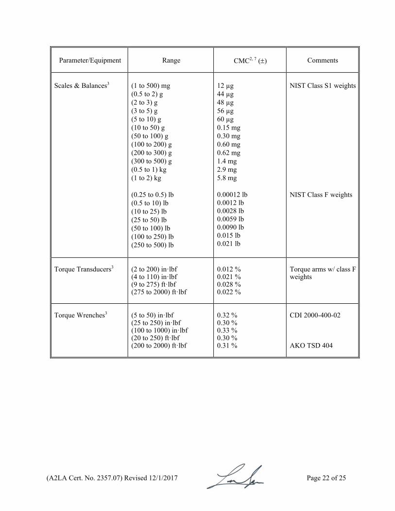
Scales & Balances3
(1 to 500) mg (0.5 to 2) g (2 to 3) g (3 to 5) g (5 to 10) g (10 to 50) g (50 to 100) g (100 to 200) g (200 to 300) g (300 to 500) g (0.5 to 1) kg (1 to 2) kg (0.25 to 0.5) lb (0.5 to 10) lb (10 to 25) lb (25 to 50) lb (50 to 100) lb (100 to 250) lb (250 to 500) lb
12 µg 44 µg 48 µg 56 µg 60 µg 0.15 mg 0.30 mg 0.60 mg 0.62 mg 1.4 mg 2.9 mg 5.8 mg 0.00012 lb 0.0012 lb 0.0028 lb 0.0059 lb 0.0090 lb 0.015 lb 0.021 lb
NIST Class S1 weights NIST Class F weights
Torque Transducers3
(2 to 200) in·lbf (4 to 110) in·lbf (9 to 275) ft·lbf (275 to 2000) ft·lbf
0.012 % 0.021 % 0.028 % 0.022 %
Torque arms w/ class F weights
Torque Wrenches3
(5 to 50) in·lbf (25 to 250) in·lbf (100 to 1000) in·lbf (20 to 250) ft·lbf (200 to 2000) ft·lbf
0.32 % 0.30 % 0.33 % 0.30 % 0.31 %
CDI 2000-400-02 AKO TSD 404
(A2LA Cert. No. 2357.07) Revised 12/1/2017 Page 23 of 25
Parameter/Equipment
Range
CMC2 ()
Comments
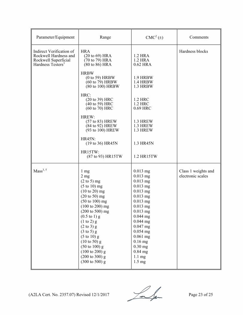
Indirect Verification of Rockwell Hardness and Rockwell Superficial Hardness Testers3
HRA
(20 to 69) HRA (70 to 79) HRA (80 to 86) HRA
HRBW
(0 to 59) HRBW (60 to 79) HRBW (80 to 100) HRBW
HRC: (20 to 39) HRC (40 to 59) HRC (60 to 70) HRC
HREW:
(57 to 83) HREW (84 to 92) HREW (93 to 100) HREW
HR45N:
(19 to 36) HR45N HR15TW:
(87 to 93) HR15TW
1.2 HRA 1.2 HRA 0.62 HRA 1.9 HRBW 1.4 HRBW 1.3 HRBW 1.2 HRC 1.2 HRC 0.69 HRC 1.3 HREW 1.3 HREW 1.3 HREW 1.3 HR45N 1.2 HR15TW
Hardness blocks
Mass3, 5
1 mg 2 mg (2 to 5) mg (5 to 10) mg (10 to 20) mg (20 to 50) mg (50 to 100) mg (100 to 200) mg (200 to 500) mg (0.5 to 1) g (1 to 2) g (2 to 3) g (3 to 5) g (5 to 10) g (10 to 50) g (50 to 100) g (100 to 200) g (200 to 300) g (300 to 500) g
0.013 mg 0.013 mg 0.013 mg 0.013 mg 0.013 mg 0.013 mg 0.013 mg 0.013 mg 0.013 mg 0.044 mg 0.044 mg 0.047 mg 0.054 mg 0.061 mg 0.16 mg 0.30 mg 0.84 mg 1.1 mg 1.5 mg
Class 1 weights and electronic scales
(A2LA Cert. No. 2357.07) Revised 12/1/2017 Page 24 of 25
Parameter/Equipment
Range CMC2 ()
Comments
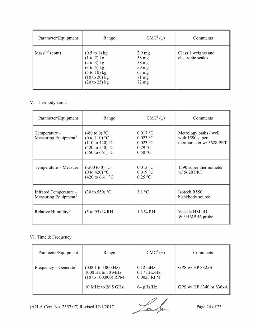
Mass3, 5 (cont)
(0.5 to 1) kg (1 to 2) kg (2 to 3) kg (3 to 5) kg (5 to 10) kg (10 to 20) kg (20 to 25) kg
2.9 mg 58 mg 58 mg 59 mg 65 mg 71 mg 72 mg
Class 1 weights and electronic scales
V. Thermodynamics
Parameter/Equipment
Range CMC2 ()
Comments
Temperature – Measuring Equipment3
(-80 to 0) °C (0 to 110) °C (110 to 420) °C (420 to 550) °C (550 to 661) °C
0.017 °C 0.023 °C 0.023 °C 0.29 °C 0.50 °C
Metrology baths / well with 1590 super thermometer w/ 5628 PRT
Temperature – Measure
3 (-200 to 0) °C (0 to 420) °C (420 to 661) °C
0.013 °C 0.019 °C 0.25 °C
1590 super thermometer w/ 5628 PRT
Infrared Temperature – Measuring Equipment
3
(30 to 550) °C 3.1 °C
Isotech R550 blackbody source
Relative Humidity
3
(5 to 95) % RH
1.3 % RH
Vaisala HMI 41 Wi/ HMP 46 probe
VI. Time & Frequency
Parameter/Equipment
Range CMC2 ()
Comments
Frequency – Generate3
(0.001 to 1000 Hz) 1000 Hz to 50 MHz (10 to 100,000) RPM 10 MHz to 26.5 GHz
0.12 mHz 0.17 nHz/Hz 0.0023 RPM 64 pHz/Hz
GPS w/ HP 3325B GPS w/ HP 8340 or 836xA
(A2LA Cert. No. 2357.07) Revised 12/1/2017 Page 25 of 25
Parameter/Equipment
Range CMC2 ()
Comments
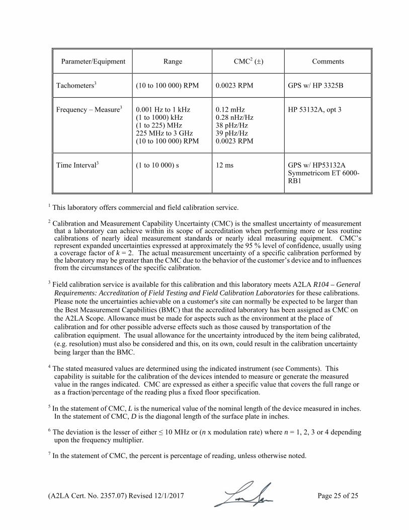
Tachometers3
(10 to 100 000) RPM
0.0023 RPM GPS w/ HP 3325B
Frequency – Measure3
0.001 Hz to 1 kHz (1 to 1000) kHz (1 to 225) MHz 225 MHz to 3 GHz (10 to 100 000) RPM
0.12 mHz 0.28 nHz/Hz 38 pHz/Hz 39 pHz/Hz 0.0023 RPM
HP 53132A, opt 3
Time Interval3
(1 to 10 000) s 12 ms
GPS w/ HP53132A Symmetricom ET 6000-RB1
1 This laboratory offers commercial and field calibration service. 2 Calibration and Measurement Capability Uncertainty (CMC) is the smallest uncertainty of measurement
that a laboratory can achieve within its scope of accreditation when performing more or less routine calibrations of nearly ideal measurement standards or nearly ideal measuring equipment. CMC’s represent expanded uncertainties expressed at approximately the 95 % level of confidence, usually using a coverage factor of k = 2. The actual measurement uncertainty of a specific calibration performed by the laboratory may be greater than the CMC due to the behavior of the customer’s device and to influences from the circumstances of the specific calibration.
3 Field calibration service is available for this calibration and this laboratory meets A2LA R104 – General
Requirements: Accreditation of Field Testing and Field Calibration Laboratories for these calibrations. Please note the uncertainties achievable on a customer's site can normally be expected to be larger than the Best Measurement Capabilities (BMC) that the accredited laboratory has been assigned as CMC on the A2LA Scope. Allowance must be made for aspects such as the environment at the place of calibration and for other possible adverse effects such as those caused by transportation of the calibration equipment. The usual allowance for the uncertainty introduced by the item being calibrated, (e.g. resolution) must also be considered and this, on its own, could result in the calibration uncertainty being larger than the BMC.
4 The stated measured values are determined using the indicated instrument (see Comments). This
capability is suitable for the calibration of the devices intended to measure or generate the measured value in the ranges indicated. CMC are expressed as either a specific value that covers the full range or as a fraction/percentage of the reading plus a fixed floor specification.
5 In the statement of CMC, L is the numerical value of the nominal length of the device measured in inches.
In the statement of CMC, D is the diagonal length of the surface plate in inches. 6 The deviation is the lesser of either ≤ 10 MHz or (n x modulation rate) where n = 1, 2, 3 or 4 depending
upon the frequency multiplier. 7 In the statement of CMC, the percent is percentage of reading, unless otherwise noted.
For the calibrations to which this accreditation applies, please refer to the laboratory’s Calibration Scope of Accreditation.
Accredited Laboratory
A2LA has accredited
TEKTRONIX, INC. Bothell, WA
for technical competence in the field of
Calibration
This laboratory is accredited in accordance with the recognized International Standard ISO/IEC 17025:2005 General requirements for the competence of testing and calibration laboratories. This laboratory also meets the requirements of
ANSI/NCSLI Z540-1-1994 and any additional program requirements in the field of calibration. This accreditation demonstrates technical competence for a defined scope and the operation of a laboratory quality management system (refer to joint ISO-ILAC-
IAF Communiqué dated 8 January 2009).
Presented this 4th day of December 2015. _______________________ President & CEO For the Accreditation Council Certificate Number 2357.07 Valid to June 30, 2018 Revised May 22, 2017