Embed Size (px)
Citation preview
Scintillation Methods for the Determination of Density and Moisture Content of Soils and Similar Granular Systems SHUNIL E. ROY, Research Associate, and HANS F. WINTERKORN, Professor of Civil Engineering, School of Engineering, Princeton University.
Nuclear methods for moisture and density determinations in soils have reached a point of development that makes them valuable tools to the engineer and scientist. The paper f i rs t traces the history of the available techniques and discusses the underlying scientific principles as well as the characteristics of the various available probes and of their components. Subsequently, the principles and available methods of scintillation detection are described and are applied to the design of actual moisture and density probes. The performance of these probes in laboratory and extensive field tests are given and their advantages and shortcomings pointed out. Emphasis is placed on meeting the practical problems encountered in field conditions as they affect the operation of the probes and associated electronic equipment, the preparation of holes through various soil types, the readings obtained by the instruments used, and the calculation of results, so as to give the most accurate determinations of soil moisture and density.
• ALL physical properties of natural or disturbed soil systems, whether mechanical, thermal, electrical, acoustic or optical, are functions of:
1. The volume proportions of solid, liquid and gaseous phases of the soil; 2. The intrinsic properties of these phases at the environmental temperatures; 3. The spatial arrangement of these phases, and 4. The extent, geometry and physico-chemical character of the solid-liquid, solid-
gas, gas-liquid and liquid-liquid interphases in the system. In a specific natural soil system, factors 2, 3, and 4 are usually sufficiently con
stant that the physical property under consideration can be expressed in f i rs t approximation as a function of the phase composition which can be calculated from the density and moisture content of the soil and the specific gravities of its components. Knowledge of density and moisture content is, therefore, basic with respect to the understanding of any and every physical property of a soil system and also to the predicting of the variation of such properties as a result of weather, and seasonally induced variation in soil moisture and density. Obviously, there exists a definite need for simple, dependable and speedy methods of determining moisture contents and densities of soils in the field. The traditional methods are destructive, time consuming and cumbersome. Even the improved types of electric resistance blocks for moisture determination possess important limitations. References (45), (153) and (131) give comparisons of the advantages and limitations of different methods. The most promising methods for easy and speedy moisture and density determinations are those based on the use of nuclear radiation. They are: (a) determination of soil density from the absorption or scattering of Gamma rays ( y -ray densitometry), and (b) determination of moisture content by the neutron thermalizing technique (neutron hygrometry). Sufficient work has been done on and with these methods to know that they wil l keep their promise. On the other hand much work is st i l l necessary to make these methods and the required equipment so simple, rugged and dependable that any workman can use i t with a minimum of instruction and also with a minimum of radiation hazard. The purpose of the present work was to contribute to this development with special emphasis on the use of scintillation detection which, in addition to other advantages, permits the employment of low-intensity radiation sources.
58
59
HISTORICAL REVIEW Initial research on the determination of soil density by gamma ray scattering was
performed by.Krueger (97) at Cornell University, whereas Pieper (118) and Yates (172) appear to have been the f i r s t to use the thermalizing of neutrons for measuring moisture content. Significant engineering research on the use of these methods for in situ determination of soil density and moisture content was performed by Belcher and his associates, also at Cornell University, in the course of a project sponsored by the Civil Aeronautics Administration, U. S. Department of Commerce. In their f i rs t published report of 1950, (7) Belcher and his co-workers demonstrated the great potentialities of their gamma-ray densitometer and their neutron hygrometer. The latter employed silver or rhodium foils whose activation by slow neutron bombardment was measured by means of a Geiger-Mueller tube. Previously, Berdan and Bernhard (11) at Rutgers University had demonstrated that soil density could be measured nondestruc-tively by means of x-rays; however, the necessary equipment was rather bulky and the methodology, involved. In 1952, Belcher and his associates reported on an adaptation of the nuclear techniques to measure soil density and moisture content in thin surface layers (8). Probe modifications were reported in 1953 (33), the main one following an earlier design by Gardner and Kirkham (54) using a BFs continuous detecting device for slow neutrons. With the exception of Bernhard (13) and Timblin (154), all subsequent workers have used G-M tubes for the detector of the gamma ray densitometer (25, 75, 99, 58,131,165) and radioisotope cobalt 60 of varying intensities for the source. For neutron~hygrometry either GM tubes in combination with neutron activated foils (7,25,144,156) or BFs-filled proportional counters have been used (154,137,162). Several investigators have used B'" lined BF3-counters which have the advantages of greater stability, efficiency, smaller size and of operating at much lower voltages than BFs-counters. However, these counters are expensive.
Earlier work on nuclear moisture meters made use of Po-Be sources, (7,144,156). Such sources are cheap, their chief asset, however, is low gamma radiation. Unfortunately, Po-Be has a half-life of a mere 140 days. Later, investigators used Ra-Be which has a half-life of 1,620 years; this source is fairly inexpensive but has the great disadvantage of very heavy gamma emission, (147,163). One or two workers have used Ra D-Be sources which have low gamma emission and a half-life of 22 years; these sources, however, are e:q>ensive (37).
The moisture meter has come out so far only as a single probe instrument which contains both source and detector. The probes employing the foil-activation system are usually about 1 in. in diameter. The probes utilizing BFs-counters are generally about 2in. indiameter. Thedensitometershavegenerallybeenof the single probe type, employing a geometry involving gamma-ray scattering (9, 25, 76). Gamma-ray attenuating geometry, employing two parallel tubes, one containing the source, the other the detector, has beenusedby some workers (13, 131, 165). The former system is simpler for field measurements, although theoretically not quite so accurate and capable of narrow spatial resolution as the two-probe system. The only reported workusing scintillation detection known to the authors is that of Bernhard and Chasek (13) at Rutgers University. These investigators used a 2 in. D x 1 4 in. Nal(Tl) crystal, with a photomultiplier tube that appears to be an RCA 931A type, though it is not reported as such m the paper. The tube was housed in a shield of the dimensions 5.25 in. dia. by 16 in. The two-probe geometry employing a 60 mc. cobalt 60 source was was used to measure densities of as great as 4-foot widths of soil, where the greater sensitivity of scintillation detection was used to advantage.
Several workers have used simple portable survey meters to measure the intensity of radiation picked up by the detector in the densitometer (131,165). Others have employed absolute counting scalers (7,33, 54, 75); Timblin (154y~usiH"a dosimeter. For measuring the radiation from slow neutron detection, some have used commercial or laboratory devised amplifiers and scalers (9, 54, 58, 72, 76,78,138,146,147,156,162).
Swanson (151) working with Van Bavel and Underwood developed an excellent stable and sensitive portable survey meter to handle pulses f rom aB*" lined BF3 counter when activated by slow neutrons. Another portable instrument has been designed and further modified by Stone, et al (147). This instrument utilizes four cold cathode glow transfer
60
decade counter tubes.
T H E O R E T I C A L C O N S I D E R A T I O N S
Gamma Ray Densitometry
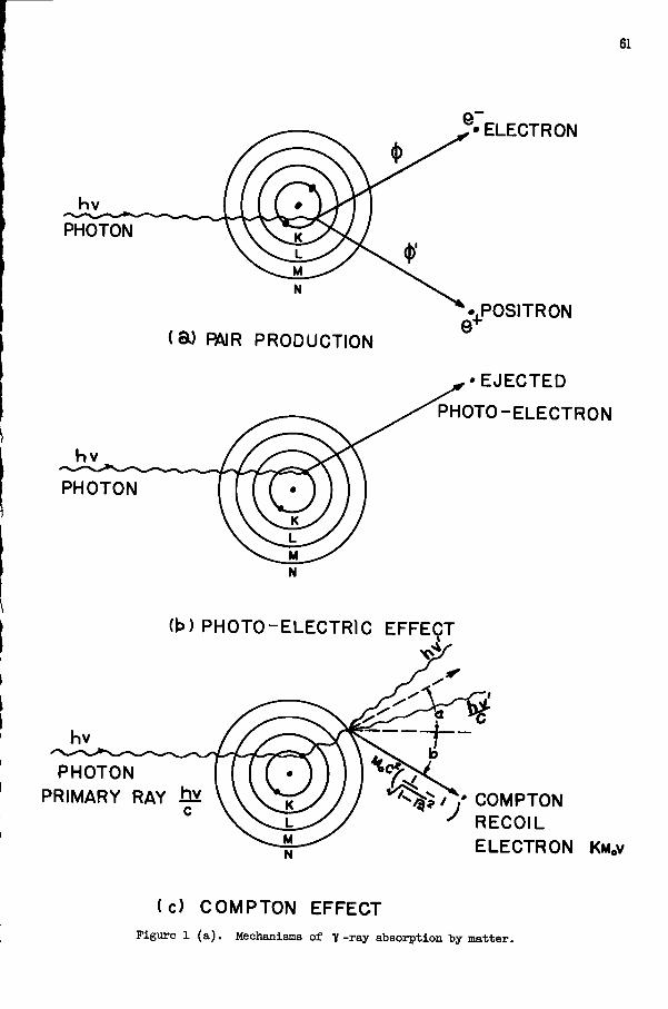
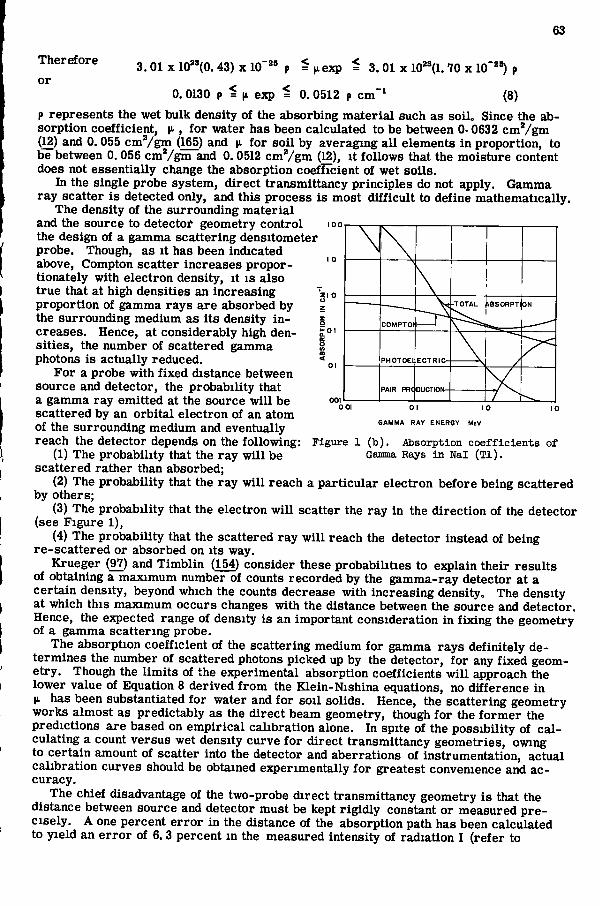
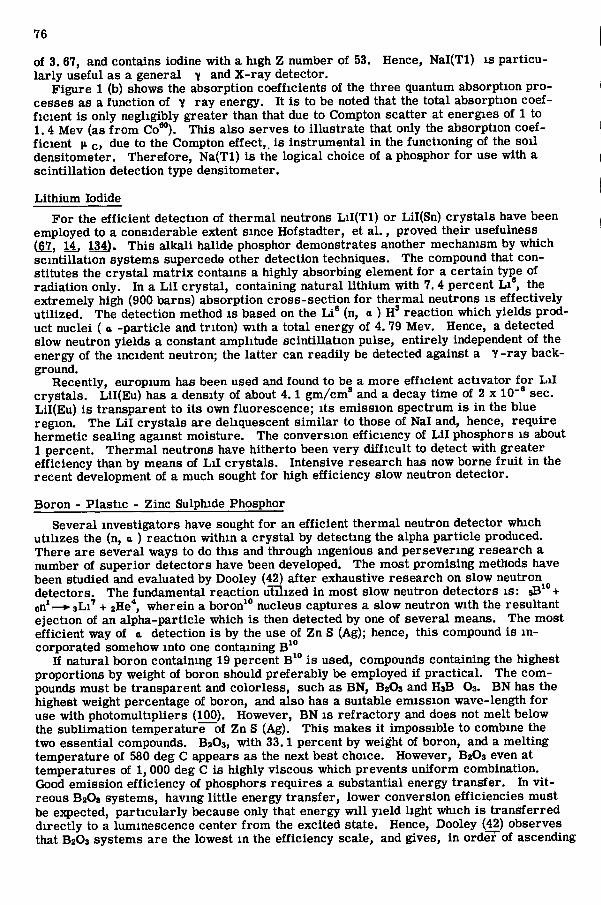
The scientif ic principles underlying gamma ray densitometry have been discussed by severa l investigators (6, 7,25, 111). F o r detailed theoretical understanding, the reader i s r e f e r r e d to the following references: (12, 41, 97, 111, 142). Only a cursory survey of the more important principles can be given here. There are three processes involved in the absorption of X - or l - r a y quanta. These are shown schematically m Figure 1. The total absorption coefficient H- i s , therefore, the sum of the three absorption coefficients, corresponding to these three processes : the photoelectric effect |i pair production |JL pp^ and the Compton effect |i q, S O that:
[ i = N ( | i p + H . p p + |i c)cin"^ (1)
where N i s the number of atoms per cm' . At energies above 0.3 Mev for the lighter elements, there i s no absorption by the
photo-electric process (hence !«• p = O) , though this i s the predominant mechanism of absorption at low energy levels below 0.1 Mev. Energy i s not absorbed by pair p r o duction below 1.02 Mev, but i s increasingly so with increas ing energy. However, up to approximately 2. 5 Mev, this mechanism i s s carce ly involved. The Compton effect remains nearly constant in absorbancy at energies f rom 0 to about 0. 5 Mev; then it decreases gradually with increas ing energy. In the range of energy of 0. 35 to 2. 5 Mev for the lighter elements, the Compton effect ( j i q ) i s almost the sole mechanism of absorption. T h i s i s c l ear ly seen in F igure l b which graphically shows the respective absorption coefficients for each of the three processes of "y - r a y absorption by N a l ( T l ) a s a function of y - r a y energy. Hence, radioisotope Co60, which decays with the e m i s sion of gamma photons at 1. 33 and 1.17 Mev, becomes an ideal source because its energy i s almost solely absorbed by the Compton effect by elements found in the so i l and because of its ready availability and low cost. F o r a l l pract ica l purposes, Co60 may be considered essentially to decay mono-energetically with a mean energy of 1.25 Mev.
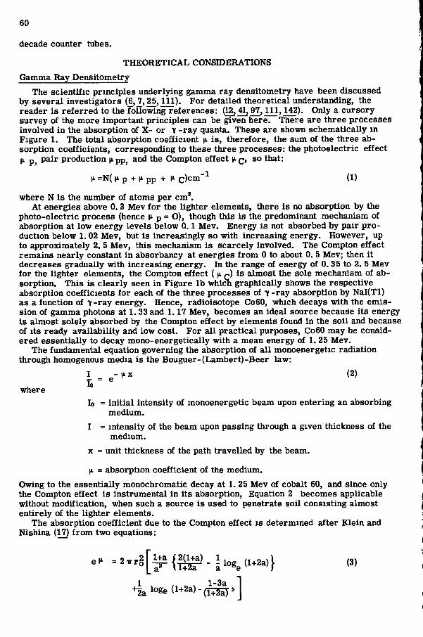
The fundamental equation governing the absorption of a l l monoenergetic radiation through homogenous media i s the Bouguer- (Lambert ) -Beer law:
I _ - l ^ x (2)
lo = init ial intensity of monoenergetic beam upon entering an absorbing medium.
I = intensity of the beam upon passing through a given thickness of the medium.
X = unit thickness of the path travel led by the beam.
|i. = absorption coefficient of the medium.
Owing to the essentially monochromatic decay at 1. 25 Mev of cobalt 60, and since only the Compton effect i s instrumental in its absorption. Equation 2 becomes applicable without modification, when such a source i s used to penetrate soi l consisting almost entirely of the lighter elements.
The absorption coefficient due to the Compton effect i s determined after Kle in and Nishina (17) f rom two equations:
+ 2 a l o g e ( l + 2 a ) - ( l ^ a
where
61
e
• E L E C T R O N
hv
PHOTON
( a ) PMR P R O D U C T I O N
P H O T O N
P O S I T R O N
• E J E C T E D
P H O T O - E L E C T R O N
(b) P H O T O - E L E C T R I C E F F E C T
P H O T O N PRIMARY RAY J^Y >f? / COMPTON
R E C O I L E L E C T R O N KM.V
( c ) C O M P T O N E F F E C T
Figiire 1 ( a ) . Mechanisms of 7 -ray absorption by matter.
62
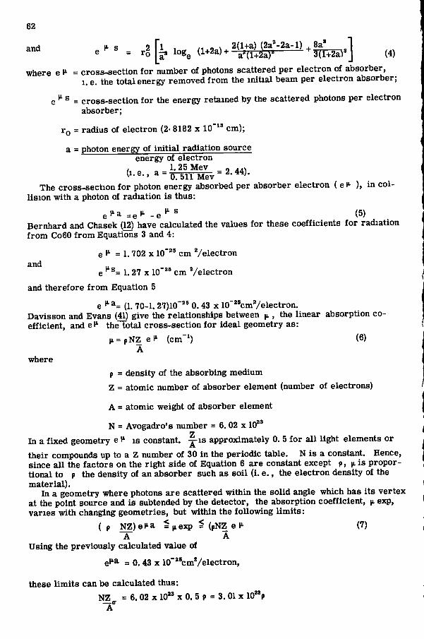
and „ 1 s 2 f l , „ „ / . .^-v . 2(l+a) (2a ' -2a- l ) ^ 8a '
where 6 1^= cross-sect ion for number of photons scattered per electron of absorber, 1. e. the total energy removed from the init ial beam per electron absorber;
e ® = cross-sect ion for the energy retained by the scattered photons per electron absorber;
ro = radius of electron (2- 8182 x 10"" cm);
a = photon energy of init ial radiation source energy of electron
/, „ „ 1.25 Mev „ j..^
The cross-sect ion for photon energy absorbed per absorber electron ( e ) , in co l l is ion with a photon of radiation i s thus:
e t ' a ^e*' - e ^ (5) Bernhard and Chasek (12) have calculated the values for these coefficients for radiation f rom Co60 f r o m Equations 3 and 4:
= 1. 702 X 10"" cm Ve lec tron and
e ' ^= 1. 27 X 10"" c m Ve lec tron
and therefore from Equation 5
e^^= (1. 70-1.27)10'" 0.43 x 10""cmVelectron. Davisson and Evans (41) give the relationships between |i, , the l inear absorption coefficient, and e l ' the total cross-sect ion for ideal geometry as :
pNZ e H' (cm"') (6) A
(1 =
where
P = density of the absorbing medium
Z = atomic number of absorber element (number of electrons)
A = atomic weight of absorber element
N = Avogadro's number = 6. 02 x 10**
In a f ixed geometry e i s constant, - ^ i s approximately 0. 5 for a l l light elements or
their compounds up to a Z number of 30 in the periodic table. N i s a constant. Hence, since a l l the factors on the right side of Equation 6 are constant except p, |i i s proportional to p the density of an absorber such as so i l ( i . e . , the electron density of the material) .
In a geometry where photons a r e scattered within the sol id angle which has its vertex at the point source and i s subtended by the detector, the absorption coefficient, |i exp, var i e s with changing geometries, but within the following l imits :
( p NZ)eH.a ^jie:q? ^ (pNZ e Ii (7) A A
Using the previously calculated value of
el^a = 0.43 X 10""cmVelectron,
these l imits can be calculated thus:
NZ = 6. 02 X 10*' X 0. 5 p = 3.01 X 10"P
63
Therefore
or 3.01 X 10"(0. 43) X 10"" p ^ exp = 3.01 x 10"(1.70 x lO"^"^ p
0.0130 p = (i exp = 0. 0512 p cm"' (8)
1
- T O T A L ) \ B S O R P T | O N \ ^ 1 ^
COMPTOr 1
- T O T A L ) \ B S O R P T | O N \ ^ 1 ^
PHOTOEl E C T R I C -
PAIR PRC D U C T I O N -
G A M M A R A Y E N E R G Y MeV
1 ( b ) . Absorption coefficients of Gamma Rays in Nal ( T l ) .
p represents the wet bulk density of the absorbing mater ia l such as so i l . Since the absorption coefficient, |i , for water has been calculated to be between 0- 0632 c m V g m (12) and 0. 055 c m V g m (165) and v for so i l by averaging a l l elements in proportion, to be between 0.056 c m V g m and 0.0512 c m V g m (12), it follows that the moisture content does not essential ly change the absorption coefficient of wet soi l s .
In the single probe system, direct transmittancy principles do not apply. Gamma ray scatter i s detected only, and this process i s most difficult to define mathematically.
The density of the surrounding mater ia l and the source to detector geometry control the design of a gamma scattering densitometer probe. Though, as it has been indicated above, Compton scatter increases proportionately with electron density, it i s also true that at high densities an increasing proportion of gamma r a y s are absorbed by = the surrounding medium as its density i n - | c r e a s e s . Hence, at considerably high den- o s i t ies , the number of scattered gamma S photons is actually reduced.
F o r a probe with fixed distance between source and detector, the probability that a gamma ray emitted at the source wi l l be scattered by an orbital electron of an atom of the surrounding medium and eventually reach the detector depends on the following: Figure
(1) The probability that the ray wi l l be scattered rather than absorbed;
(2) The probability that the ray wi l l reach a part icular electron before being scattered by others;
(3) The probability that the electron wi l l scatter the ray in the direction of the detector (see F igure 1),
(4) The probability that the scattered ray w i l l reach the detector instead of being re - sca t tered or absorbed on its way.
Krueger (97) and T imbl in (154) consider these probabilities to explain their resu l t s of obtaining a maximum number of counts recorded by the gamma-ray detector at a certa in density, beyond which the counts decrease with increasing density. The density at which this maximum occurs changes with the distance between the source and detector. Hence, the expected range of density i s an important consideration in fixing the geometry of a gamma scattering probe.
The absorption coefficient of the scattering medium for gamma r a y s definitely determines the number of scattered photons picked up by the detector, for any fixed geometry. Though the l imits of the experimental absorption coefficients w i l l approach the lower value of Equation 8 derived from the Kle in-Nishina equations, no difference in |i has been substantiated for water and for so i l solids. Hence, the scattering geometry works almost as predictably as the direct beam geometry, though for the former the predictions are based on empir ica l calibration alone. In spite of the possibility of c a l culating a count versus wet density curve for direct transmittancy geometries, owing to certain amount of scatter into the detector and aberrations of instrumentation, actual calibration curves should be obtained experimentally for greatest convenience and a c curacy .
The chief disadvantage of the two-probe direct transmittancy geometry i s that the distance between source and detector must be kept rigidly constant or measured p r e c ise ly . A one percent e r r o r in the distance of the absorption path has been calculated to yield an e r r o r of 6.3 percent in the measured intensity of radiation I (refer to
64
Equation 2) in an average reading of soi l density measurement, in the set-up employed by Bernhard and Chasek (13). It i s extremely difficult to make para l le l holes to any great depth in the f ie ld and to maintain them equidistant throughout.
SLOWING DOWN LENGTH DIFFUSION LENGTH
B a s i c Pr inc ip le s of Neutron Moderating Moisture Meter
F o r a thorough discuss ion of the theory governing the neutron scattering moisture meter, the reader i s r e f e r r e d to the following works: (54,166,168,172,173,96) . Only the important fundamentals are reviewed here.
A minera l so i l contains hydrogen mainly in three forms . F i r s t l y , the soi l minera l s contain some hydrogen, but this amount i s rather constant and its proportion by weight i s negligible. Secondly, the organic matter in so i l s contains about 5 percent of hydrogen by weight. Since the organic matter content of most m i n e r a l top-soils ranges f rom 2 to 6 percent, and i s fa i r ly constant, at most 0. 3 percent of the total weight of a m i n e r a l s o i l . is contributed by the hydrogen content of i ts organic matter. Water, which contains 11 percent by weight of hydrogen and which i s generally present in appreciable quantities, contains most of the hydrogen present in a minera l soi l .
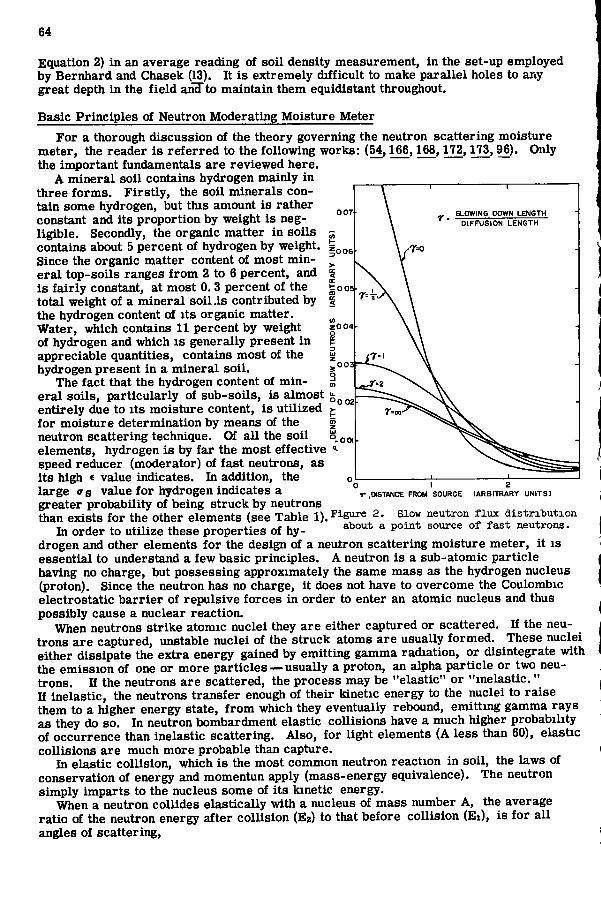
The fact that the hydrogen content of mine r a l soi ls , part icular ly of sub-soi l s , i s almost entirely due to its moisture content, i s uti l ized for moisture determination by means of the | neutron scattering technique. Of a l l the soi l • elements, hydrogen i s by far the most effective speed reducer (moderator) of fast neutrons, as i ts high c value indicates. In addition, the large <rs value for hydrogen indicates a greater probability of being struck by neutrons than exists for the other elements (see Table 1). Figure 2. slow neutron flux distribution
In order to utilize these properties of hy- ^ °^ ^^^ neutrons, drogen and other elements for the design of a neutron scattering moisture meter, it i s essential to understand a few bas ic principles . A neutron i s a sub-atomic part ic le having no charge, but possess ing approximately the same mass as the hydrogen nucleus (proton). Since the neutron has no charge, it does not have to overcome the Coulombic electrostatic b a r r i e r of repuls ive forces in order to enter an atomic nucleus and thus possibly cause a nuclear reaction.
When neutrons s tr ike atomic nuclei they are either captured or scattered. If the neutrons a r e captured, unstable nuclei of the struck atoms are usually formed. These nuclei either dissipate the extra energy gained by emitting gamma radiation, or disintegrate with the emiss ion of one or more part ic les — usually a proton, an alpha partic le or two neutrons. If the neutrons are scattered, the process may be "elastic" or "inelast ic ." If inelastic , the neutrons transfer enough of their kinetic energy to the nuclei to r a i s e them to a higher energy state, f rom which they eventually rebound, emitting gamma r a y s as they do so. In neutron bombardment elast ic col l is ions have a much higher probability of occurrence than inelastic scattering. Also , for light elements (A l e s s than 60), elastic col l is ions are much more probable than capture.
In e last ic coll is ion, which i s the most common neutron reaction in soi l , the laws of conservation of energy and momentun apply (mass-energy equivalence). The neutron simply imparts to the nucleus some of its kinetic energy.
When a neutron coll ides e last ical ly with a nucleus of mass number A, the average ratio of the neutron energy after col l i s ion (Eg) to that before col l is ion ( E i ) , i s for a l l angles of scattering,
I .DISTANCE FROM SOURCE (ARBITRARY UNITS)
65
The average energy E ^ of a neutron after n col l is ions, have an original energy state
i« E „ = E „ e""* (10)
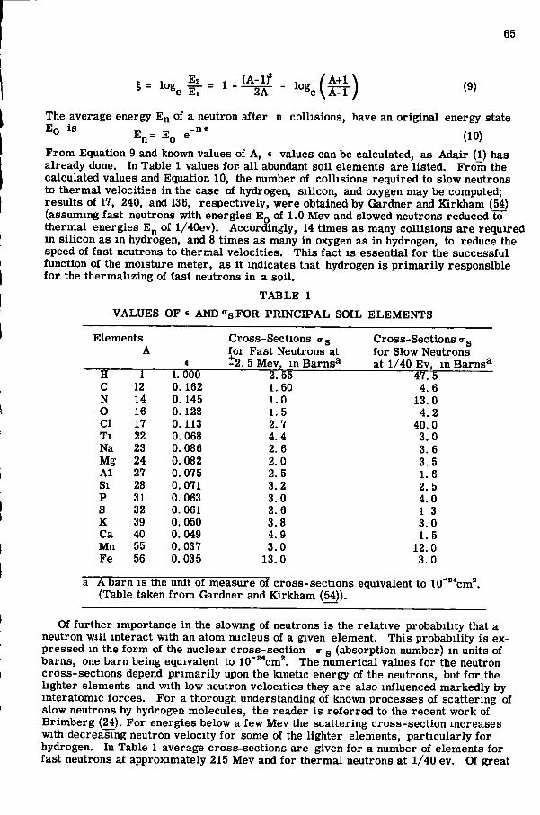
F r o m Equation 9 and known values of A, < values can be calculated, as Adair (^) has already done. In Table 1 values for a l l abundant so i l elements are l isted. F r o m the calculated values and Equation 10, the number of col l is ions required to slow neutrons to thermal velocities in the case of hydrogen, s i l icon, and oxygen may be computed; resul ts of 17, 240, and 136, respectively, were obtained by Gardner and K i r k h a m (54) (assuming fast neutrons with energies E q of 1.0 Mev and slowed neutrons reduced to thermal energies E^^ of l / 40ev) . Accordingly, 14 t imes a s many col l is ions a r e required in s i l icon as m hydrogen, and 8 t imes as many in oxygen as in hydrogen, to reduce the speed of fast neutrons to thermal velocities. T h i s fact i s essential for the success fu l function of the moisture meter, as it indicates that hydrogen i s p r i m a r i l y responsible for the thermalizing of fast neutrons in a so i l .
T A B L E 1
V A L U E S O F e AND<fsFOR P R I N C I P A L S O I L E L E M E N T S
Elements Cross -Sec t ions o-g Cross -Sec t ions <rg A for F a s t Neutrons at for Slow Neutrons
« - 2 . 5 Mev, in B a r n s ^ at 1/40 E v . in B a n H 1 1. 000 2. 55 47.5 C 12 0. 162 1.60 4. 6 N 14 0.145 1.0 13.0 O 16 0.128 1. 5 4 .2 C I 17 0. 113 2.7 40.0 T i 22 0.068 4.4 3 .0 Na 23 0.086 2.6 3 .6 Mg 24 0. 082 2.0 3. 5 A l 27 0.075 2. 5 1. 6 S i 28 0.071 3 .2 2. 5 P 31 0. 063 3 .0 4.0 S 32 0. 061 2.6 1 3 K 39 0.050 3 .8 3 .0 C a 40 0. 049 4 .9 1. 5 Mn 55 0. 037 3 .0 12.0 F e 56 0.035 13.0 3 .0
a A barn i s the unit of measure of cross - sec t ions equivalent to lO"**cm*. (Table taken f rom Gardner and K i r k h a m (54)).
Of further importance in the slowing of neutrons is the relat ive probability that a neutron wi l l interact with an atom nucleus of a given element. T h i s probability i s expressed in the form of the nuclear cross - sec t ion <r g (absorption number) in units of barns , one barn being equivalent to 10"**cm*. The numerical values for the neutron cross - sec t ions depend p r i m a r i l y upon the kinetic energy of the neutrons, but for the lighter elements and with low neutron velocit ies they are also influenced markedly by interatomic forces . F o r a thorough understanding of known processes of scattering of slow neutrons by hydrogen molecules, the reader i s r e f e r r e d to the recent work of B r i m b e r g (24). F o r energies below a few Mev the scattering cross - sec t ion increases with decreasing neutron velocity for some of the lighter elements, part icular ly for hydrogen. In Table 1 average cross-sect ions are given for a number of elements for fast neutrons at approximately 215 Mev and for thermal neutrons at 1/40 ev. Of great
66
47 5 significance i s the large increase in cross - sec t ion for hydrogen (-n~rc = l ^ - ^ t imes) , attending the slow-down of fast neutrons to thermal velocities. For' most other elements found in appreciable quantities m soi l , the c r o s s - sections remain much the same, with certain exceptions such as C I , N, and Mn. Hydrogen i s most effective in slowing fast neutrons both because of its high c , and its large <rs value. The former indicates the extent to which neutrons lose energy upon striking a hydrogen nucleus, while the latter indicates the probability of a nucleus being struck. When neutrons reach thermal energies, they come to thermal equilibrium with the surrounding atoms and cease to lose energy. They now scatter, in accordance with simple diffusion laws, until they are captured.
Mathematical Formulation
Certa in peculiar character i s t i c s of fast neutron emission, coll is ion, and capture, that affect radical ly the design of a nuclear moisture meter are worthy of consideration through mathematical formulation of the rate processes and reactions involved.
Gardner and K i r k h a m (54) give essentially the following theoretical discussion: If
P (r) = density of slow neutrons per unit volume in a volume element located at a distance r f rom the source of fast neutrons;
t = the time elapsed, and T = the mean life time of a neutron (T i s also the inverse of the probability of capture per unit time);
D = the diffusion coefficient, as ordinari ly defined for gas; and
Q = the rate per unit volume at which thermal neutrons are created; then, f r o m basic three dimensional diffusion theory, the equation of continuity i s :
a p / a t = D V ' ' - ( p / T ) + Q (11)
The term on the left hand side of the equation i s the time rate of variation of the density of slow neutrons in the volume element. The f i r s t t erm on the right represents the rate of increase of slow neutron-density in the volume element due to diffusion, and includes V , the Laplac ian operator. The second term on the right represents the rate at which the slow neutrons disappear because of capture, and the last t erm Q represents the rate at which slow neutrons are created by the slowing of fast ones.
Since equilibrium i s reached almost instantaneously, the p r i m a r y assumption i s : a p / 5 t = 0.
The diffusion length, L , i s now introduced. T h i s length i s equal to Ye the average distance f rom the point of origin to the point of capture of the thermal neutrons. The length includes also the distance traveled before capture and after being slowed to therm a l velocities. In terms of D and T ,
L * = D T
Hence, Equation 11 can now be written as
V^P - P / L * = - ( T / L * ) Q (12)
Q i s usually calculated by means of the "Age theory" described by Marshak (109). A c cording to this theory, Q sat is f ies the part ia l differential equation
a o / d e = V ' Q + S 8 ( e ) (13)
in which 6 i s the "symbolic age, " s i s a function dependent on the shape of the fast neutron source, and s i s the D i r a c s - function. Phys ica l ly , Q has the dimension of L * . The D i r a c s - function i s defined by the parameters 8 (r) = 0 if r ? 0; and by y s (r) dr = 1, if the range of integration includes r = 0.
It i s essential to obtain the boundary conditions in order to solve Equations 10 and 11, which i s difficult to do. The diffusion length L has been defined above. The sloTving-down length i s defined as the average distance a neutron must trave l in a medium before
67
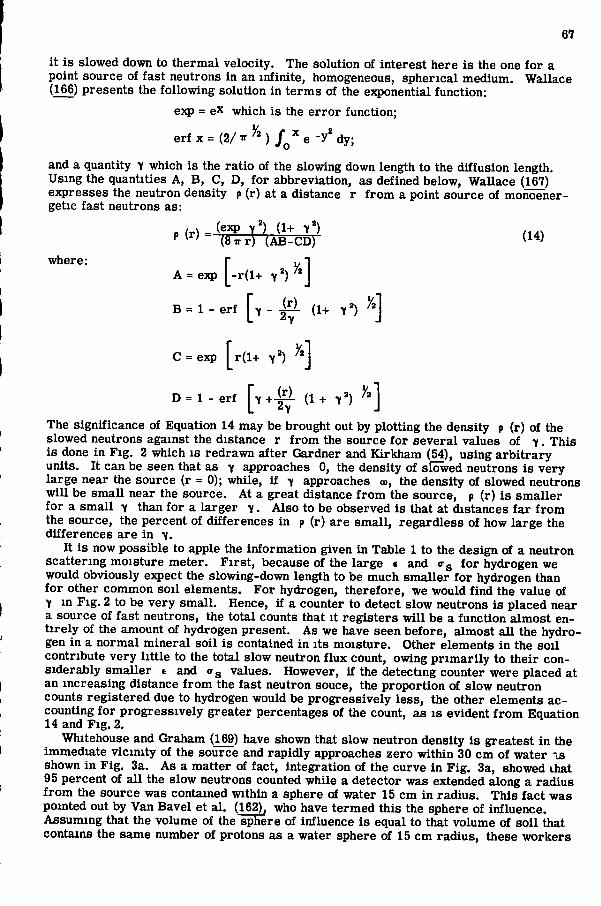
it i s slowed down to thermal velocity. The solution of interest here i s the one for a point source of fast neutrons in an infinite, homogeneous, spher ica l medium. Wallace (166) presents the following solution in terms of the ejcponential function:
exp = eX which is the e r r o r function;
e r f x = ( 2 / ^ ^ M / o ' ' e - y ' d y ;
and a quantity Y which is the ratio of the slowing down length to the diffusion length. Using the quantities A, B , C , D , for abbreviation, as defined below, Wallace (167) expresses the neutron density p (r) at a distance r from a point source of monoener-getic fast neutrons as:
P "" - ( 8 ^ r ) ( A B - C D ) ^ ^
A = e:?) - r ( l + 7*)^'
B = 1 - erf Y - i i L (1+ Y * )
where:
2 Y
C = exp r ( l + Y ' ) ^ \
2-y D = l - e r f 1^7+-^ ( 1 + Y ' ) ' ' J
The significance of Equation 14 may be brought out by plotting the density p (r) of the slowed neutrons against the distance r from the source for s evera l values of Y . T h i s i s done in F i g . 2 which i s redrawn after Gardner and Kirkham (54), using arb i t rary units. It can be seen that as Y approaches 0, the density of slowed neutrons i s very large near the source (r = 0); while, if Y approaches oo, the density of slowed neutrons wi l l be s m a l l near the source. At a great distance f rom the source, p (r) i s smal l er for a s m a l l Y than for a larger Y . A l so to be observed i s that at distances far f rom the source, the percent of differences in p (r) are smal l , regardless of how large the differences are in Y .
It i s now possible to apple the information given in Table 1 to the design of a neutron scattering moisture meter. F i r s t , because of the large c and o-g for hydrogen we would obviously expect the slowing-down length to be much smal ler for hydrogen than for other common so i l elements. F o r hydrogen, therefore, we would find the value of Y in F i g . 2 to be very smal l . Hence, if a counter to detect slow neutrons i s placed near a source of fast neutrons, the total counts that it reg i s ters wi l l be a function almost ent ire ly of the amount of hydrogen present. A s we have seen before, almost a l l the hydrogen in a normal minera l so i l i s contained in its moisture. Other elements in the so i l contribute very little to the total slow neutron flux count, owing p r i m a r i l y to their considerably smal l er e and o-g values. However, if the detecting counter were placed at an increas ing distance f r o m the fast neutron souce, the proportion of slow neutron counts registered due to hydrogen would be progress ively l e s s , the other elements a c counting for progress ively greater percentages of the count, as i s evident f rom Equation 14 and F i g . 2.
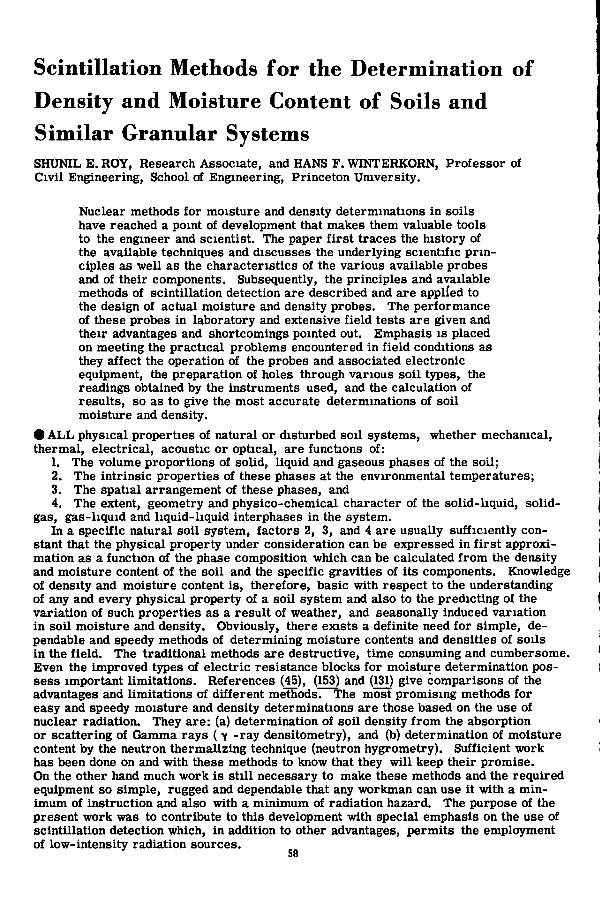
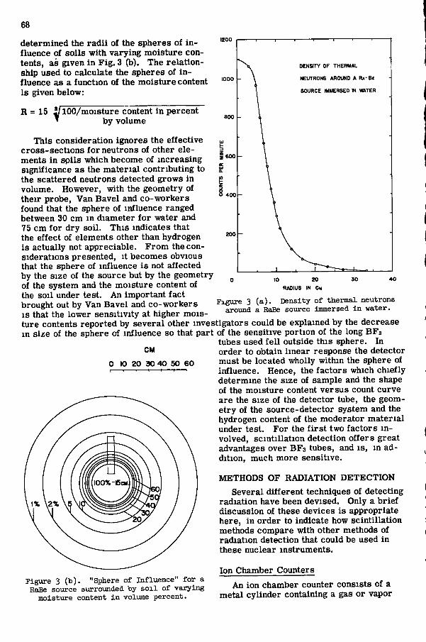
Whitehouse and Graham (169) have shown that slow neutron density i s greatest in the immediate vicinity of the source and rapidly approaches zero within 30 c m of water as shown in F i g . 3a. A s a matter of fact, integration of the curve in F i g . 3a, showed ihat 95 percent of a l l the slow neutrons counted while a detector was extended along a radius f rom the source was contained within a sphere of water 15 cm in radius . T h i s fact was pointed out by Van Bave l et a l . (162), who have termed this the sphere of influence. Assuming that the volume of the sphere of influence i s equal to that volume of so i l that contains the same number of protons as a water sphere of 15 cm radius , these workers
68
DENSITY OF THERMAL
NEUTRONS AROUND A R . - B f
SOURCE IMMERSED IN WATER
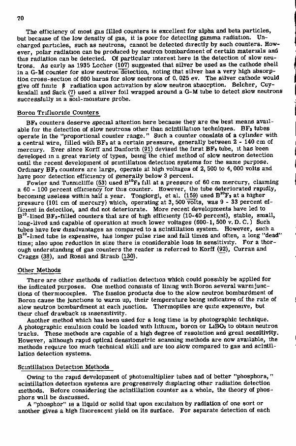
determined the rad i i of the spheres of i n fluence of so i l s with varying moisture contents, as given in F i g . 3 (b). The relat ionship used to calculate the spheres of i n fluence as a function of the moisture content i s given below:
R = 15 ^ 1 0 0 / m o i s t u r e content in percent ^ by volume
T h i s consideration ignores the effective cross - sec t ions for neutrons of other elements in spi l s which become of increas ing significance as the mater ia l contributing to the scattered neutrons detected grows in volume. However, with the geometry of their probe, Van Bave l and co -workers found that the sphere of influence ranged between 30 cm in diameter for water and 75 cm for dry soil . T h i s indicates that the effect of elements other than hydrogen i s actually not appreciable. F r o m the considerations presented, it becomes obvious that the sphere of influence i s not affected by the s ize of the source but by the geometry of the system and the moisture content of the soi l under test. An important fact brought out by Van B a v e l and co -workers I S that the lower sensitivity at higher mois ture contents reported by severa l other investigators could be explained by the decrease in s ize of the sphere of influence so that part of the sensitive portion of the long B F a
Figure 3 (a). Density of thermal neutrons around a RaBe source Immersed in water.
CM
0 10 20 30 4 0 50 6 0
Figure 3 (b). "Sphere of Influence" for a RaBe source surrounded by s o i l of varying
moisture content i n volume percent.
tubes used f e l l outside this sphere. In order to obtain l inear response the detector must be located wholly within the sphere of influence. Hence, the factors which chiefly determine the s ize of sample and the shape of the moisture content v e r s u s count curve are the s ize of the detector tube, the geometry of the source-detector system and the hydrogen content of the moderator mater ia l under test. F o r the f i r s t two factors in volved, scintil lation detection offers great advantages over B F s tubes, and i s , in addition, much more sensitive.
M E T H O D S O F R A D I A T I O N D E T E C T I O N
Several different techniques of detecting radiation have been devised. Only a brief discussion of these devices i s appropriate here, in order to indicate how scintil lation methods compare with other methods of radiation detection that could be used in these nuclear instruments.
Ion Chamber Counters
An ion chamber counter consists of a metal cylinder containing a gas or vapor

69
generally at atmospheric pressure . A metal rod which is insulated from the c y l inder I S held para l l e l to the axis of the cylinder. When any radiation capable of ionizing the gas enters the chamber through its thin window, it ionizes the gas. B e cause there i s a s m a l l potential set a c r o s s the chamber and the rod, the ions flow towards the opposite polarit ies and produce a faint ionization current which can be measured by an electrometer. Gamma r a y s can readily be detected by such counters . However, neutrons do not directly cause ionization as they have no charge. Hence, the chamber has to be lined with Lithium foil or a powder containing Boron. Neutrons passing through the foi l generate a - part ic les by the n-a reaction, and these alpha part ic les cause the gas to ionize . The ion chamber i s bulky and i s capable of giving only a rate of radiation on an electrometer, being incapable of resolving individual pulses that follow closely upon each other. However, Koontz and Hal l (89) devised a gas counter capable of being used as an ionization chamber or as a proportional counter which gives individual pulses that are proportional to the inten-
U J 5 0
PHOSPHOR THICKNESS (MM)
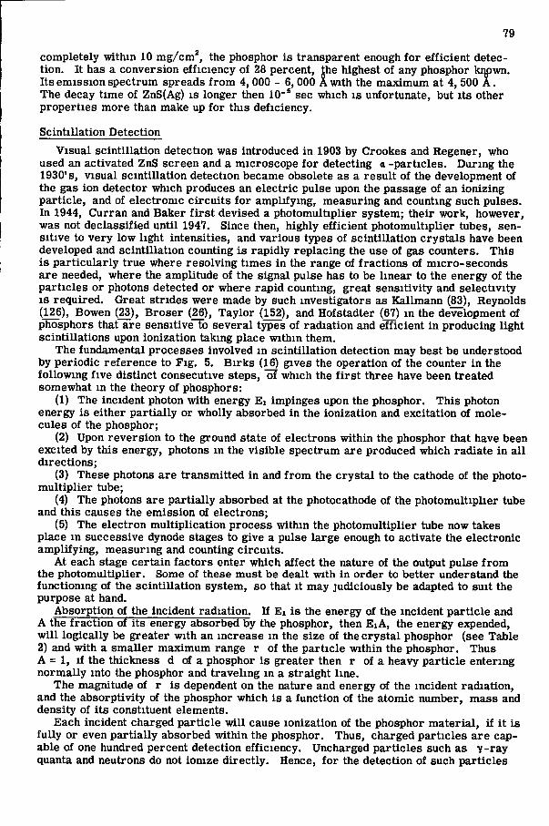
Figure h. Relative efficiency of Heutron ___ Phosphor vs. Phosphor thickness.
sity of the p r i m a r y ionization caused by an incident radiation photon.
Proportional Counters
These counters are basical ly the same as an ionization chamber except that a higher potential e lectr ic f ie ld exists between the wall and the central rod. In operation, the p r i m a r y ions that are produced upon radiation striking an atom of the gas m the chamber are accelerated by the high potential to cause secondary ions, and these in turn cause tert iary ionization, and so on, so that a sizable current i s produced momentarily at the electrodes; this current , however, i s s t i l l proportional to tlie p r i m a r y ionization charge. The chief disadvantage of this system, though of more general use than the simple ionization chamber, i s its long resolving time, so that at fast counting rates the pulses tend "to pile up" upon each other. These counters are also generally rather large.
Geiger Mueller Counters
These detectors depend on much the same ionization principle, but have been developed to a far greater extent so that there are s evera l kinds, shapes and s i ze s of such tubes. In a Geiger-Muel ler detector, the potential between the outer wall and the concentric thin wire along the axis of the gas cylinder i s considerable. At the potential of operation, the p r i m a r y ions produced by radiation are highly accelerated, causing a great many rapid secondary ionizations so that a large short- l ived pulse i s produced at the electrodes. The pulse so produced i s not proportional in magnitude to the charge of the pr imary ionization event, tending to be fa ir ly the same s ize irrespect ive of the or ig inal charge causing the cascade of ions. The chief advantages of this system a r e its versat i l i ty , its dependability, s m a l l s ize and convenience in use, and, above a l l , its stability in the region of its exciting potential plateau. The sensitivity of such tubes i s very constant in spite of fluctuations of applied voltage within the plateau range. Such tubes are capable of fa i r ly high counting rates as there are built- in mechanisms for suddenly quenching the pulse produced by the cascade of ionization sequences, after it reg i s ters a charge at the electrodes.
70
The efficiency of most gas f i l led counters i s excellent for alpha and beta part ic les , but because of the low density of gas, it i s poor for detecting gamma radiation. Uncharged part ic les , such as neutrons, cannot be detected directly by such counters. However, polar radiation can be produced by neutron bombardment of certa in mater ia ls and this radiation can be detected. Of part icular interest here i s the detection of slow neutrons. A s early as 1935 Locher (107) s u ^ e s t e d that s i lver be used as the cathode shel l in a G - M counter for slow neutron~c[etection, noting that s i lver has a very high absorption cross - sec t ion of 600 barns for slow neutrons of 0. 025 ev. The s i lver cathode would give off finite p radiation upon activation by slow neutron absorption. Be lcher , Cuy-kendall and Sack (7) used a s i lver foi l wrapped around a G - M tube to detect slow neutrons successful ly in a soi l -moisture probe.
Boron Tr i f luor ide Counters
B F s counters deserve special attention here because they are the best means a v a i l able for the detection of slow neutrons other than scintil lation techniques. B F s tubes operate in the "proportional counter range ." Such a counter consists of a cylinder with a central wire , f i l led with B F s at a certain pres sure , generally between 2 - 140 c m of mercury . E v e r since Korff and Danforth (91) devised the f i r s t B F s tube, it has been developed in a great variety of types, being the chief method of slow neutron detection until the recent development of scintillation detection systems for the same purpose. Ordinary B F s counters are large, operate at high voltages of 2, 500 to 4,000 volts and have poor detection efficiency of generally below 3 percent.
Fowler and Tunnicliffe (53) used B^^Fs f i l l at a pres sure of 60 c m mercury , c laiming a 60 - 100 percent efficiency for this counter. However, the tube deteriorated rapidly, becoming use less within half a year . Tongiorgi, et a l . (159) used B' Fs at a higher pres sure (101 cm of mercury) which, operating at 3, 500 volts, was 9 - 3 3 percent efficient in detection, and did not deteriorate. More recent developments have led to B^''-lined B F s - f i l l e d counters that are of high efficienty (10-40 percent), stable, smal l , long-lived and capable of operation at much lower voltages (600-1, 500 v. D. C . ) Such tubes have few disadvantages as compared to a scintil lation system. However, such a B*°- l ined tube i s expensive, has longer pulse r i s e and fa l l times and often, a long "dead" time; also upon reduction in s ize there i s considerable loss in sensitivity. F o r a thorough understanding of gas counters the reader i s r e f e r r e d to Korff {92), C u r r a n and Craggs (38), and R o s s i and Straub (130).
Other Methods
T h e r e are other methods of radiation detection which could possibly be applied for the indicated purposes. One method consists of lining with Boron severa l w a r m junctions of thermocouples. The f i s s ion products due to the slow neutron bombardment of Boron cause the junctions to warm up, their temperature being indicative of the rate of slow neutron bombardment at each junction. Thermopi les are quite expensive, but their chief drawback i s insensitivity.
Another method which has been used for a long time i s by photographic technique. A photographic emulsion could be loaded with lithium, boron or L i B O s to obtain neutron tracks . These methods are capable of a high degree of resolution and great sensitivity. However, although rapid optical densitometric scanning methods are now available, the methods require too much technical s k i l l and are too slow compared to gas and sc int i l lation detection systems.
Scintillation Detection Methods
Owing to the rapid development of photomultiplier tubes and of better "phosphors, " scintillation detection systems are progress ively displacing other radiation detection methods. Before considering the scintillation counter as a whole, the theory of phosphors wi l l be discussed.
A "phosphor" i s a liquid or solid that upon excitation by radiation of one sort or another gives a high fluorescent yie ld on its surface . F o r separate detection of each
71
E . I N C I D E N T RADIAT ION QUANTUM
CRYSTAL
PHOR
NC DENT LffiHT PHOTON
POLISHED ALUMINUM R E F L E C T I N G CONTAINER
S C I N T I L L A T I O N
F L U I D OPTIC S E A L (DOW-CORNING D"C 2 0 0 SILICONE) INTERNAL CONDUCTIVE COATING
S E M I - T R A N S P A R E N T PHOTOCATHODE
G R I L L A C C E L E R A T I N G E L E C T R O D E
- S H I E L D
G L A S S E N V E L O P E
PHOTOMULTIPLER TUBE
1-10 • DYNODES 11 ANODE
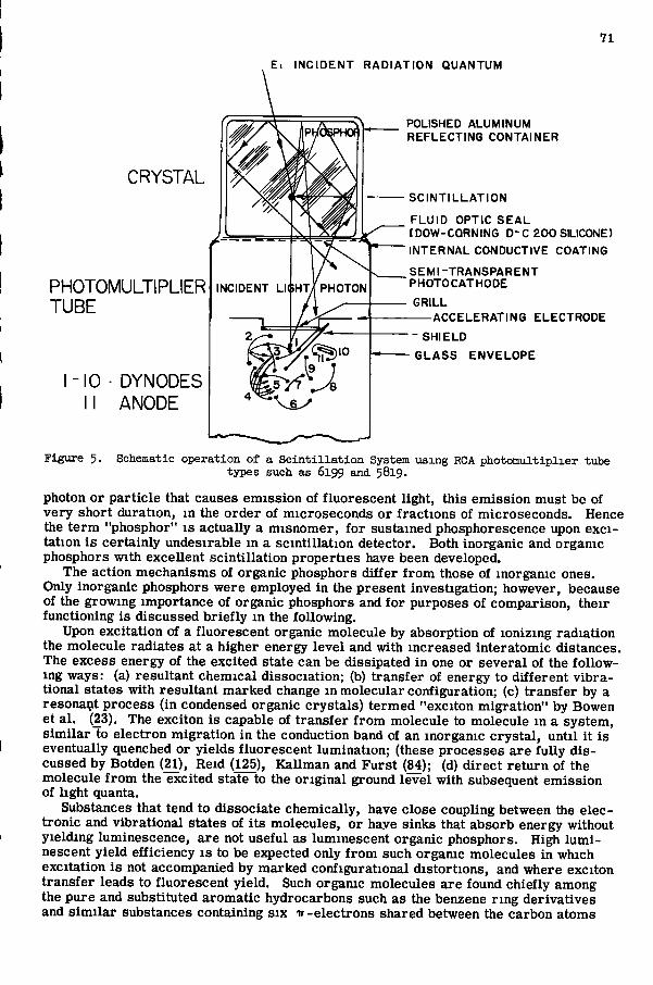
Figure 5. Schematic operation of a Sc i n t i l l a t i o n System using RCA photomultiplier tube types such as 6199 and. 5819.
photon or particle that causes emiss ion of fluorescent light, this emiss ion must be of very short duration, in the order of microseconds or fractions of microseconds. Hence the term "phosphor" i s actually a misnomer, for sustained phosphorescence upon e x c i tation i s certainly undesirable in a scinti l lation detector. Both inorganic and organic phosphors with excellent scintillation properties have been developed.
The action mechanisms of organic phosphors differ f rom those of inorganic ones. Only inorganic phosphors were employed in the present investigation; however, because of the growing importance of organic phosphors and for purposes of comparison, their functioning i s d iscussed brief ly in the following.
Upon excitation of a fluorescent organic molecule by absorption of ionizing radiation the molecule radiates at a higher energy level and with increased interatomic distances. The excess energy of the excited state can be dissipated in one or s evera l of the following ways: (a) resultant chemical dissociation; (b) transfer of energy to different v i b r a tional states with resultant marked change in molecular configuration; (c) transfer by a resonant process (in condensed organic crys ta l s ) termed "exciton migration" by Bowen et a l . (23). The exciton i s capable of transfer from molecule to molecule in a system, s imi lar to electron migration in the conduction band of an inorganic c r y s t a l , until it i s eventually quenched or yie lds f luorescent lumination; (these processes a r e ful ly d i s cussed by Botden (21), Reid (125), Ka l lman and F u r s t (84); (d) direct return of the molecule f rom the excited state to the original ground level with subsequent emiss ion of light quanta.
Substances that tend to dissociate chemically, have close coupling between the e lectronic and vibrational states of i ts molecules, or haye s inks that absorb energy without yielding luminescence, are not useful as luminescent organic phosphors. High l u m i nescent yield efficiency i s to be ejcpected only from such organic molecules in which excitation i s not accompanied by marked configurational distortions, and where exciton transfer leads to fluorescent yield. Such organic molecules are found chiefly among the pure and substituted aromatic hydrocarbons such as the benzene r ing derivatives and s i m i l a r substances containing s ix ir-e lectrons shared between the carbon atoms
72
00
90
80
K 60 <
m K 50 <
> cn z u
UJ
>
t : 4 0
30
U 2 0
I 0
s - R AN( )E OF
M AX. VA LUt
1 \ / \ / /
_ i
o c 1 1
> <
H >'l z .O
W
c < r
cr _ 1
g UJ " -\ _ i
LU u cc
_ i UJ \ => i j j -
:
/ 1 00 1 1 1 \ x: -
1 / 1 1 1 \ / \ 1 ^ .
Figure 6.
1000 2000 3000 4000 5000 6000 7000 8000
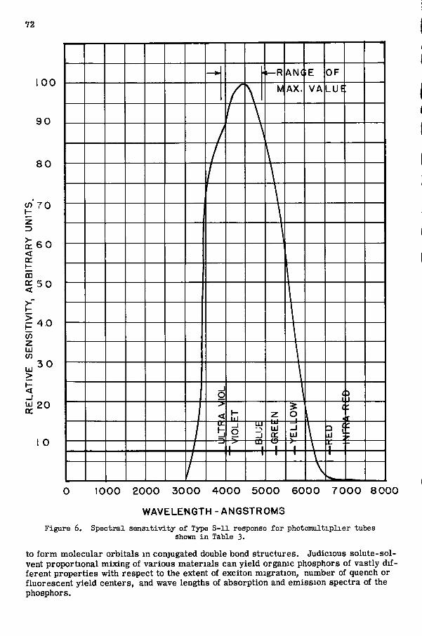
WAVELENGTH-ANGSTROMS Spectral sensxtivity of Tjrpe S-11 response for photomultxplier tubes
shown i n Table 3.
to form molecular orbitals in conjugated double bond structures . Judicious solute-solvent proportional mixing of various materials can yield organic phosphors of vastly different properties with respect to the extent of exciton migration, number of quench or fluorescent yield centers, and wave lengths of absorption and emiss ion spectra of the phosphors.
L U C I T E -
1=
'382 - f ' - s " " ' PHOTOMULTIPLIER TUBE
-l<2
n|oo
AMPHENOL TYPE RG - 5 9 U CABLE
0 9 3 0 " I D
. 3 " 4 - 4 0 SET SCREWS 8
| " 0 0 -RING GROOVES
73
•VOLTAGE DIVIDER
-POTTED BASE SECTION
MUMETAL „ MAGNETIC SHIELD I D
l O D - j ^ WALL THICKNESS
O 9 0 5 " I D ALUMINUM TUBING
LITHIUM IODIDE EUROPIUM ACTIVATED CRYSTAL
GLASS WOOL SPACER
LEAD SEPARATING SHIELD - O-RING GROOVE
3" — g 4 - 4 0 SET SCREWS
. a -RING GROOVE
. 0 . 2 ' D I A M E T E R • 0 1 2 5 ' D I A M E T E R - SOURCE
PIN - LEAD COLLIMATOR
3"D ~A
- r
O-RING GROOVE
4 - 4 0 SET SCREWS
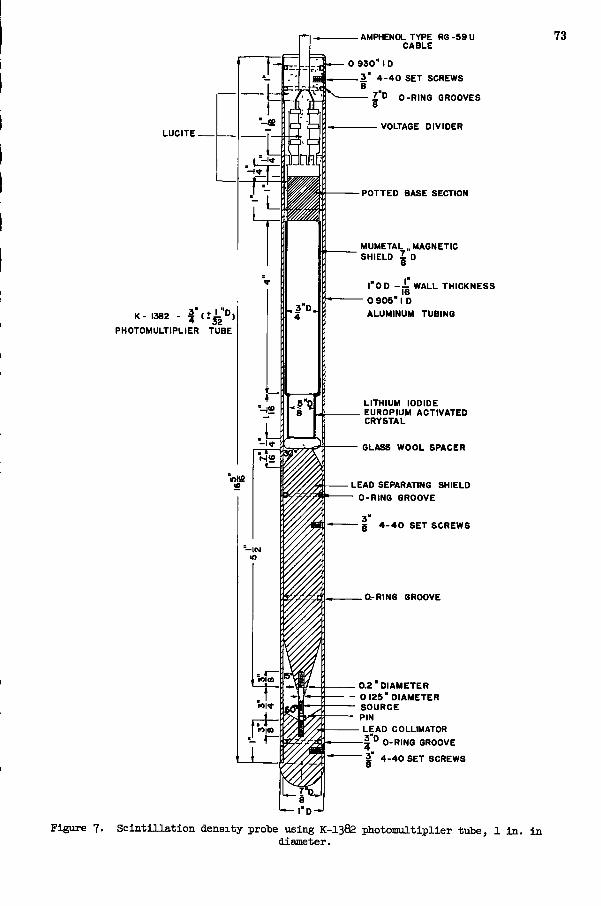
Figure 7. S c i n t i l l a t i o n density probe using K - I 3 8 2 photomultiplier tube, 1 i n . i n diameter.
74
Organic phosphors have the great advantage of very short decay t imes, in the order of 10~ sec; they are generally highly transparent to their own fluorescent emission, can readi ly be grown in large single c r y s t a l s and, because of their high hydrogen content, are efficient when used for fast neutron detection by proton reco i l within the phosphor itself. Organic phosphors are poor for gamma detection at most energies because of their low density and low Z values. They also have lower conversion efficiency and pulse-height aplitudes as compared with the more widely used inorganic phosphors.
Inorganic Phosphors
Most of the inorganic phosphors are impurity activated. There exist certain s i m i lar i t i e s of their action mechanisms to those of mixed organic phosphors. A single atom or molecule has its electronic energy states in a s er i e s of discrete levels . Upon agi tation by mutual interaction between atoms the outer energy levels of electrons in an inorganic c r y s t a l lattice line up to form ser i e s of continuous "allowed" energy bands
10-01
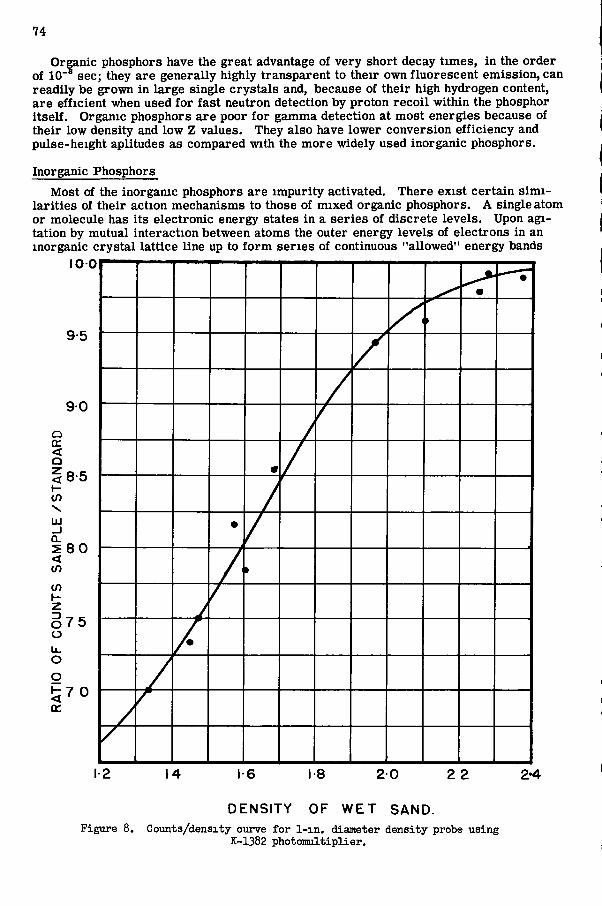
DENSITY OF W E T SAND. Figure 8. Counts/densxty curve for l-xn. diameter density probe using
K-1382 photomultiplier.
75
separated by "forbidden" bands. The inner electronic levels r emain essential ly unperturbed maintaining their normal character . In the normal state, lower energy bands are f i l led with electrons, whereas the higher ones remain empty. Electrons can move free ly through the dimensions of the c r y s t a l in their own respective bands without additional activation energy. Movement of electrons in a f i l l ed band causes no e l ec tr i ca l conduction since equal numbers are forced to move m opposite directions. B y the absorption of energy quanta, electrons in a f i l led band may r i s e into the empty bands, leaving positive holes in the f i l led bands. Conductivity then occurs owing to the motion of both the excited electrons and the positive holes. T h i s i s a model of an insulator with perfect c r y s t a l lattice. Actual phosphor c r y s t a l s have lattice defects which cause variations in the energy bands that produce local electronic energy levels within the normally forbidden band. If such levels are vacant, electrons may be drawn into these centers. There are three main types of centers: (a) Cuench centers in which excitation energy i s changed into thermal energy and lost without radiation; (b) luminescence centers in which the excited electron returns to the ground state causing emiss ion of a light quantum; (c) electron traps, wherein electrons are captured under emiss ion of thermal radiation. T h i s thermal energy may r a i s e electrons to an excited state from which they may return to the conduction band, or f a l l to the ground state by radiation-l e s s transitions through metastable leve ls of the impurity center.
F o r a phosphor to be an efficient scinti l lator, luminescence centers must predominate. T h i s i s guaranteed by activating the phosphor with s m a l l quantities of ionic i m purit ies that are evenly distributed throughout the c r y s t a l lattice. These impurity ions cause additional levels of energy which form luminescence centers and markedly affect the energy band system. The efficiency of phosphors depends also on the wave length of the absorbed photons. Irradiation of a phospor at the fundamental absorption band of its matr ix lattice has a low quantum efficiency (generally 20 percent or less ) because of competitive capture of excited electrons by luminescence and quenching centers . Incorporation of an activator produces new optical absorption bands of longer wave length which are added to the fundamental absorption bands. These represent additional electronic levels formed by the activator luminescence centers between the conduction band and the ground state. Irradiation of a phosphor at its activator band wave lengths could yield quantum eff iciencies of 100 percent if the absorbed energy passed completely into an excited l eve l of luminescent centers and provided that no electrons migrated through the conduction band to be captured by quenching centers. The properties and functioning of certain phosphors used in the present investigation wi l l now be discussed.
Sodium Iodide
Thal l ium-act ivated sodium iodide i s one of the best and most widely used sc int i l la tion phosphors. It i s one of a group of a lkal i halide phosphors whose action mechanisms differ slightly from the general behavior of inorganic phosphors that has been discussed above. In impurity activated a lkal i halide phosphors, there are metastable levels e s tablished at luminescence centers formed by the impurity ions. These metastable levels operate somewhat like electron traps as they capture electrons and do not permit e lec tronic transition to the ground state. However, by absorption of thermal energy, the electron in a metastable state can be ra i sed to an excited level which has an allowed transition to the ground state yielding emiss ion of a light quantum. T h i s accounts for the generally longer decay t imes of such phosphors (~ 10"' sec ); however, this phosphorescence has not res tr ic ted the use of Nal ( T l ) .
Only the Z n S phosphor and its re lat ives have a higher energy conversion efficiency than N a l ( T l ) , variously estimated as between 8 - 1 1 percent for the latter phosphor. The fluorescent emiss ion spectrum of N a l ( T l ) has a mean wavelength of 4,100 A with a width of 850 A to half of the maximum intensity. T h i s makes it ideal for most photo-mult ipl iers with typical S-11 spectral response. It i s also highly transparent to its own emitted light radiation as absorption occurs only below 3, 000 A . The actual decay time of N a l ( T l ) I S 2. 5 X 10"'' sec at room temperature; it increases with increas ing temperature. C r y s t a l s of N a l ( T l ) can be made in large s izes ; it has a high specif ic gravity
76
of 3. 67, and contains iodine with a high Z number of 53. Hence, N a l ( T l ) i s part icular ly useful as a general y and X - r a y detector.
F igure 1 (b) shows the absorption coefficients of the three quantum absorption processes as a function of y ray energy. It i s to be noted that the total absorption coefficient i s only negligibly greater than that due to Compton scatter at energies of 1 to 1. 4 Mev (as f r o m Co*°). T h i s a l so s e r v e s to i l lustrate that only the absorption coefficient |i c, due to the Compton effect,, i s instrumental in the functioning of the soi l densitometer. Therefore , N a ( T l ) i s the logical choice of a phosphor for use with a scintil lation detection type densitometer.
Lithium Iodide
F o r the efficient detection of thermal neutrons L i I ( T l ) or Lil (Sn) c r y s t a l s have been employed to a considerable extent since Hofstadter, et a l . , proved their usefulness (67. 14. 134). T h i s a lkal i halide phosphor demonstrates another mechanism by which scintillation systems supercede other detection techniques. The compound that constitutes the c r y s t a l matr ix contains a highly absorbing element for a certain type of radiation only. In a L i l c r y s t a l , containing natural lithium with 7. 4 percent L i * , the extremely high (900 barns) absorption cross - sec t ion for thermal neutrons i s effectively util ized. The detection method i s based on the L i ' (n, o ) H* reaction which yields product nuclei ( a -part ic le and triton) with a total energy of 4. 79 Mev. Hence, a detected slow neutron yields a constant amplitude scintil lation pulse, entirely independent of the energy of the incident neutron; the latter can readily be detected against a 7 - r a y background.
Recently, europium has been used and found to be a more efficient activator for L i l c r y s t a l s . L i l ( E u ) has a density of about 4.1 g m / c m ' and a decay time of 2 x 10"' sec . L i l ( E u ) i s transparent to its own fluorescence; its emiss ion spectrum i s in the blue region. The L i l c r y s t a l s are deliquescent s i m i l a r to those of Nal and, hence, require hermetic seal ing against moisture. The conversion efficiency of L i l phosphors i s about 1 percent. T h e r m a l neutrons have hitherto been very difficult to detect with greater efficiency than by means of L i l c rys ta l s . Intensive r e s e a r c h has now borne fruit in the recent development of a much sought for high efficiency slow neutron detector.
Boron - P l a s t i c - Zinc Sulphide Phosphor
Several investigators have sought for an efficient thermal neutron detector which uti l izes the (n, a ) reaction within a c r y s t a l by detecting the alpha partic le produced. T h e r e are s e v e r a l ways to do this and through ingenious and persevering r e s e a r c h a number of superior detectors have been developed. The most promising methods have been studied and evaluated by Dooley (42^ after exhaustive r e s e a r c h on slow neutron detectors. The fundamental reaction util ized in most slow neutron detectors i s : 5B^° + on^—»" sLi ' ' + jHe*, wherein a boron" nucleus captures a slow neutron with the resultant ejection of an alpha-partic le which i s then detected by one of s e v e r a l means. The most efficient way of a detection i s by the use of Z n S (Ag); hence, this compound i s i n corporated somehow into one containing B*°
U natural boron containing 19 percent i s used, compounds containing the highest proportions by weight of boron should preferably be employed if prac t i ca l . The compounds must be transparent and color less , such as B N , B2O3 and H3B O3. B N has the highest weight percentage of boron, and also has a suitable emiss ion wave-length for use with photomultipliers (100). However, B N i s re fractory and does not melt below the sublimation temperature of Zn S (Ag). T h i s makes it impossible to combine the two essential compounds. BzOa, with 33.1 percent by weight of boron, and a melting temperature of 580 deg C appears as the next best choice. However, B203 even at temperatures of 1, 000 deg C i s highly viscous which prevents uniform combination. Good emiss ion efficiency of phosphors requires a substantial energy transfer . In v i t reous Ba03 systems, having little energy transfer , lower conversion eff ic iencies must be expected, part icular ly because only that energy wi l l y ie ld light which i s t rans ferred directly to a luminescence center from the excited state. Hence, Dooley (42) observes that BgOa systems are the lowest in the efficiency scale , and gives, in order of ascending
77
efficiency: vitreous organo-boron compounds containing conjugated multiple bonds, crysta l l ine organo-boron compounds, and ionic boron compounds.
Kasha (86), Kal lraan (83) and Dooley (42) worked a great deal with Anthracene -Bg Os systems, but did not produce a totally satisfactory detector m spite of exhaustive theoretical calculation, and explanation of the phys ical mechanisms involved. A brief resume i s included here, because a highly efficient slow neutron detector operating on s i m i l a r principles , devised by Sun, Malmberg and Pec jak (149) has been used most successful ly in investigations here.
F i e l d s of slow neutrons a r e generally found where fast neutrons and gamma e m i s sion i s also present if not prol i f ic . Hence, a most essential feature in a slow neutron detector i s its selective detection m order to prevent y and fast neutron detection. If sys tems a r e found wherein the quenching curve fa l l s off sharply to 0 beyond 5 or 10 ev, neutrons with energies above this would remain undetected. P las t i c and organic c r y s tals have rat ios of conversion eff ic iencies for y and for a , E ^ : E ^ , in the order of 50:1 and 15:1 respectively, whereas inorganic c r y s t a l s have rat ios of mere ly 0. 5:1 to 5:1. Hence the higher the proportion of inorganic c r y s t a l s in the phosphor the smal l er wi l l be the proportion of counts attributable to gamma r a y s . The s ize of the phosphor must be calculated so ap to adequately absorb a maximum percentage of neutrons and yet a minimum number of Y photons. However, there are further factors such as optical density to be considered part icular ly in mult i -crysta l l ine phosphors. The Boron compound - Z n S (Ag) type of detector operates in the following three distinct stages of events, each event having its own probability of occurrence:
1. A slow neutron i s captured by a B I O nucleus within the mater ia l of the phosphor; 2. The resultant alpha partic le f rom the B I O (n, a ) L i ' ' reaction reaches a Zn S
(Ag) granule with sufficient energy to cause scintillation; 3. The f luorescence from the point of scintil lation reaches the photocathode of a
photomultiplier with adequate energy to be converted into a photoelectron. The o v e r - a l l efficiency of the scinti l lator i s then the product of the probabilities of an
event occurring in each of these three success ive stages. The thickness of a phosphor with fixed composition and density determines the prob
ability of occurrence of event 1. A s shown previously in the theory of the operation of the neutron thermalizing probe, thermal neutrons have Maxwellian distribution in matter until captured. F o r neutrons with a maximum energy between 0. 025 and 0. 05 ev, neutron absorption by a thickness d of a mater ia l i s :
Id = _ - n s (E)d
where lo
I(j = neutron flux on penetrating a thickness d of target
lo = neutron flux incident on target
s (E) = total neutron cross - sec t ion in cm^
n = number of target n u c l e i / c m '
E = energy of neutrons
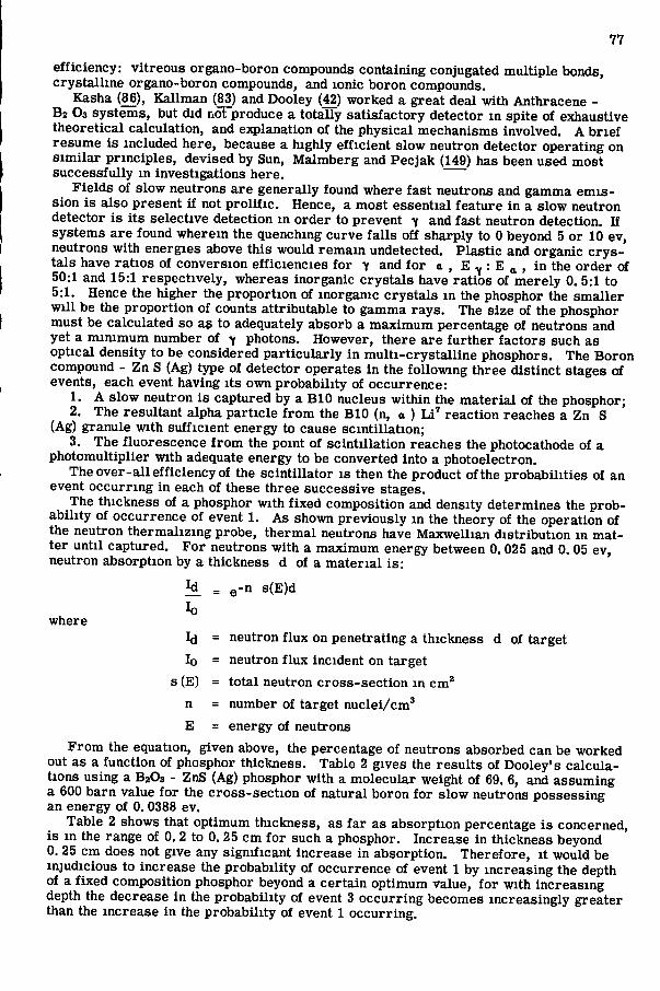
F r o m the equation, given above, the percentage of neutrons absorbed can be worked out as a function of phosphor thickness. Table 2 gives the resul ts of Dooley's ca lcu la tions using a BzOs - ZnS (Ag) phosphor with a molecular weight of 69. 6, and assuming a 600 barn value for the cross - sec t ion of natural boron for slow neutrons possessing an energy of 0. 0388 ev.
Table 2 shows that optimum thickness, as far as absorption percentage i s concerned, i s in the range of 0. 2 to 0. 25 cm for such a phosphor. Increase in thickness beyond 0. 25 c m does not give any significant increase in absorption. Therefore , it would be injudicious to increase the probability of occurrence of event 1 by increas ing the depth of a fixed composition phosphor beyond a certain optimum value, for with increasing depth the decrease in the probability of event 3 occurring becomes increasingly greater than the increase in the probability of event 1 occurring.

78
It i s possible to increase the probability of occurrence of event 2 by increasing the proportion of ZnS(Ag); this, however, would be at the expense of the probability for neutron capture as there would then necessar i ly be fewer B"" nuclei. Fur ther , the greater the quantity of ZnS(Ag) the less transparent i s the detector with a consequent reduction in the probable occurrence of event 3; also the phosphor's sensitivity to -y-radiation would be greater. It i s possible to calculate the proportions of the mixture so that the probability of event 2 occurr ing i s optimized. T h i s i s dependent on the density of the phosphor, the path length of the radiation penetration and the minimum res idual energy threshold of the luminescent center.
T A B L E 2
P E R C E N T A G E O F A B S O R P T I O N O F S L O W N E U T R O N S W I T H C H A N G E IN B2O3 - ZnS(Ag) P H O S P H O R T H I C K N E S S ( A F T E R J . A. D O O L E Y ) a
Thickness of
Phosphor in c m 0.366 0,242 0.121 0.073 0.03 6 0.005
n s ( E ) . d 6.95 4.605 2.3 1.39 0.69 0.10
Percent n Absorption 99.9 99.0 90 75 50 10
^Reference (42).
Because of the high specif ic ionization caused by a -part ic les , the incident path of an alpha partic le within the phosphor may be considered to excite an unbroken cy l indr ica l volume to the a-range R i . The excited volume V i would then be i r r ? R i , if r i i s the radius of the mean range of secondary electrons. Normal ionizing radiation may be considered to have N pr imary coll is ions in its range R, each with a volume V of a sphere at the center of which there i s the greatest concentration of secondary ionization and other energy transfer . The energy transfer process is best described by a quenching curve which has the excitation energy in the mater ia l plotted against the d i s tance f rom the pr imary ionization. The "energy threshold" i s defined as the lowest energy which, when transferred to a luminescent center, wi l l emit a photon of light. The farthest intersection of the plotted quenching curve with the horizontal threshold level defines, therefore, the parameter r , the effective radius of the excitation sphere.
Within an average excitation sphere or cylinder a s in the case of an o-ionization path, there i s a number or fraction, m, of luminescent centers. Of these, only a fraction, f, wi l l be energized and wi l l emit f luorescence. Hence, the total number of luminescent photons produced by an excitation sphere i s proportional to N m f. In terms of density of active centers per unit volume, designated by n, the photons emitted would be proportional to N V n f. The excitation sphere volume could be used just a s effectively as the more indirect probability sphere concept to determine the optimizing of the proportions of luminescent center producing mater ia l and the p r i m a r y ionization producing substance. Homogeneous distribution of these mater ia ls , and part icularly the s ize of the ZnS(Ag) crys ta l s used, can affect considerably the working properties of the phosphor.
F igure 4 redrawn from Sun, Malmberg and Pec jak (149) shows the relative efficiency a s a function of phosphor thickness of the excellent phosphor they developed. It i s to be noted that beyond a 1. 2 mm thickness, with a ZnS(Ag): "Boron P las t i c" ratio of 2. 0, owing to the greatly decreased probability of scintillations reaching the photocathode p r i m a r i l y , the efficiency of the phosphor drops off sharply, in spite of the increasing probability of higher neutron capture. The efficiency of the phosphor having a c o r r u gated surface and using a 1:2 Boron P las t i c to ZnS(Ag) mixture i s 33 percent. Gamma r a y s contributed only one percent of the total count in an experiment of counting slow neutrons f r o m a P o - B e fast neutron source surrounded by a paraff in moderator. ZnS(Ag) IS the best alpha detector known; it i s capable of 100 percent detection at proper thicknesses . Beyond a thickness of 25 mg/cm^ ZnS(Ag) crys ta l s become opaque and are therefore quite use less a s phosphors. However, for a -part i c l e s that can be stopped
79
completely within 10 mg/cm*, the phosphor is transparent enough for efficient detection. It has a conversion efficiency of 28 percent, the highest of any phosphor krjpwn. Its emiss ion spectrum spreads from 4,000 - 6, 000 A with the maximum at 4, 500 A . The decay time of ZnS(Ag) i s longer then 10"* sec which i s unfortunate, but its other properties more than make up for this deficiency.
Scintillation Detection
V i s u a l scintillation detection was introduced in 1903 by Crookes and Regener, who used an activated ZnS screen and a microscope for detecting a -part ic les . During the 1930's, v i sua l scintil lation detection became obsolete as a resul t of the development of the gas ion detector which produces an e lectr ic pulse upon the passage of an ionizing part ic le , and of electromc c ircu i t s for amplifying, measuring and counting such pulses. In 1944, C u r r a n and B a k e r f i r s t devised a photomultiplier system; their work, however, was not declass i f ied until 1947. Since then, highly efficient photomultiplier tubes, sensitive to very low light intensities, and various types of scintillation c r y s t a l s have been developed and scintil lation counting i s rapidly replacing the use of gas counters. T h i s i s part icular ly true where resolving t imes in the range of fractions of micro-seconds are needed, where the amplitude of the signal pulse has to be l inear to the energy of the part ic les or photons detected or where rapid counting, great sensitivity and selectivity i s required. Great str ides were made by such investigators as Kal lmann (83), Reynolds (126), Bowen (23), B r o s e r (26), Tay lor (152), and Hofstadter (67) m the development of phosphors that are sensitive to severa l types of radiation and V i o l e n t in producing light scintil lations upon ionization taking place within them.
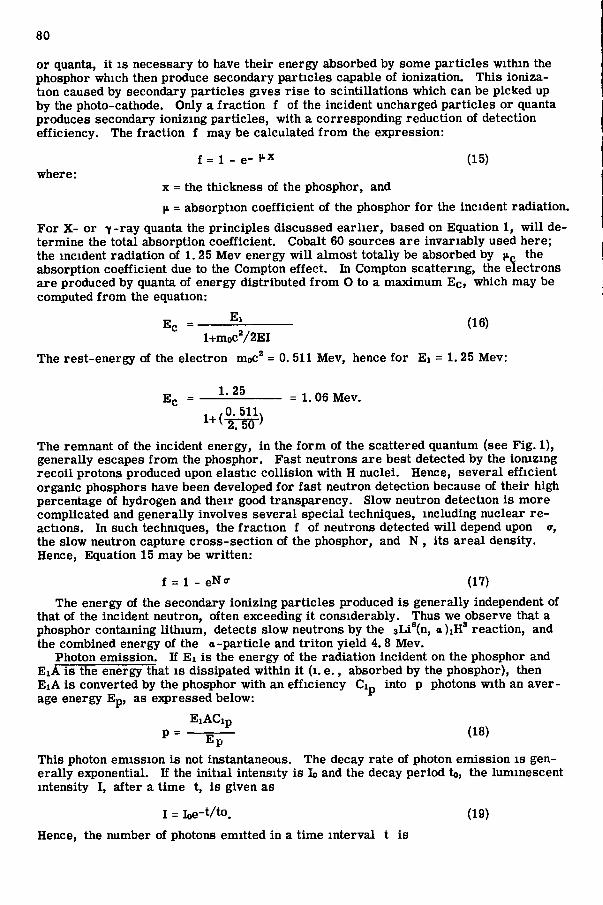
The fundamental processes involved m scintil lation detection may best be understood by periodic reference to F i g . 5. B i r k s (16) gives the operation of the counter in the following f ive distinct consecutive steps, of which the f i r s t three have been treated somewhat in the theory of phosphors:
(1) The incident photon with energy E i impinges upon the phosphor. T h i s photon energy i s either partial ly or wholly absorbed in the ionization and excitation of molecules of the phosphor;
(2) Upon revers ion to the ground state of electrons within the phosphor that have been excited by this energy, photons in the vis ible spectrum are produced which radiate in a l l directions;
(3) These photons are transmitted in and from the c r y s t a l to the cathode of the photomultiplier tube;
(4) The photons a r e partial ly absorbed at the photocathode of the photomultiplier tube and this causes the emiss ion of electrons;
(5) The electron multiplication process within the photomultiplier tube now takes place in success ive dynode stages to give a pulse large enough to activate the electronic amplifying, measuring and counting c i rcu i t s .
At each stage certain factors enter which affect the nature of the output pulse f rom the photomultiplier. Some of these must be dealt with in order to better understand the functioning of the scintil lation system, so that it may judiciously be adapted to suit the purpose at hand.
Absorption of the incident radiation. If E i i s the energy of the incident part ic le and A the fraction of its energy absorbed by the phosphor, then E i A , the energy expended, wi l l logically be greater with an increase in the s ize of the c r y s t a l phosphor (see Table 2) and with a smal l er maximum range r of the part ic le within the phosphor. Thus A = 1, if the thickness d of a phosphor i s greater then r of a heavy partic le entering normally into the phosphor and traveling in a straight l ine.
The magnitude of r i s dependent on the nature and energy of the incident radiation, and the absorptivity of the phosphor which i s a function of the atomic number, mass and density of i ts constituent elements.
E a c h incident charged part ic le wi l l cause ionization of the phosphor mater ia l , if it i s fully or even partial ly absorbed within the phosphor. Thus , charged part ic les are capable of one hundred percent detection efficiency. Uncharged part ic les such as v - r a y quanta and neutrons do not ionize directly. Hence, for the detection of such part ic les
80
or quanta, it i s necessary to have their energy absorbed by some part ic les within the phosphor which then produce secondary part ic les capable of ionization. T h i s ionization caused by secondary part ic les gives r i s e to scintillations which can be picked up by the photo-cathode. Only a fract ion f of the incident uncharged part ic les or quanta produces secondary ionizing part ic les , with a corresponding reduction of detection efficiency. The fract ion f may be calculated f rom the expression:
f = 1 - e- (15)
where: X = the thickness of the phosphor, and
|iL = absorption coefficient of the phosphor for the incident radiation.
F o r X - or -y-ray quanta the principles discussed e a r l i e r , based on Equation 1, wi l l determine the total absorption coefficient. Cobalt 60 sources a r e invariably used here; the incident radiation of 1.25 Mev energy wi l l almost totally be absorbed by (IQ the absorption coefficient due to the Compton effect. In Compton scattering, the electrons a r e produced by quanta of energy distributed f rom O to a maximum E c , which may be computed from the equation:
E l
l + m o c V 2 E I
The rest-energy of the electron moc^ = 0. 511 Mev, hence for E i = 1. 25 Mev:
E c = ^ (16)
E g = = 1. 06 Mev. . , / 0 . 511> ^ + ^ X 5 0 - )
The remnant of the incident energy, in the f o r m of the scattered quantum (see F i g . 1), generally escapes f rom the phosphor. F a s t neutrons are best detected by the ionizing reco i l protons produced upon elast ic col l is ion with H nuclei. Hence, s evera l efficient organic phosphors have been developed for fast neutron detection because of their high percentage of hydrogen and their good transparency. Slow neutron detection i s more complicated and generally involves severa l specia l techniques, including nuclear r e actions. In such techniques, the fract ion f of neutrons detected wi l l depend upon o-, the slow neutron capture cross - sec t ion of the phosphor, and N , its a r e a l density. Hence, Equation 15 may be written:
f = l - e N < r (17)
The energy of the secondary ionizing part ic les produced i s generally independent of that of the incident neutron, often exceeding it considerably. Thus we observe that a phosphor containing lithium, detects slow neutrons by the sLi°(n, a ) iH* reaction, and the combined energy of the a-part ic le and triton yield 4.8 Mev.
Photon emission. If E i i s the energy of the radiation incident on the phosphor and E i A i s the energy that i s dissipated within it ( i . e . , absorbed by the phosphor), then E l A i s converted by the phosphor with an efficiency Cip into p photons with an aver age energy E p , as ejqpressed below:
E i A C i p P = - E ^
T h i s photon emiss ion i s not instantaneous. The decay rate of photon emiss ion i s general ly e}q>onential. If the init ial intensity i s lo and the decay period to, the luminescent intensity I , after a time t, i s given as
I = loe-t/to. (19)
Hence, the number of photons emitted in a time interval t i s
81
pt =p( l - e - t / t o ) (20)
T h e shorter decay period to of a phosphor makes i t capable of better time resolution which i s a much sought for feature in phosphors as it determines its capacity of counting closely t ime-spaced scintil lations; i . e . , there i s a smal l er probability that two pulses which follow within a long decay period be counted as one.
T r a n s m i s s i o n of photons to photocathode. In order to reduce the number of s c i n tillation photons absorbed with the phosphor, y. the optical absorption coefficient of the phosphor with respect to its own f luorescence radiation should be low. Hence if T p i s the transparency and x the light path length, Tp should be as near unity as possible, s ince
Tp = e- (ix (21)
The absorption coefficient v v a n e s with the wave length of the luminescence of the phosphor. F o r c lear single c r y s t a l phosphors, T p approaches unity; for this reason, they can be used effectively in great thicknesses as in the case of Nal and of good o r ganic phosphors. In the mult i -crysta l l ine phosphors such as ZnS, where p. i s great, only l imited thicknesses can be used. The light path x i s almost invariably greater than the distance from the point of photon origin to the photocathode, as most of the light i s ref lected internally before impinging on the photo-cathode.
Only a fract ion G of the photons p produced per scintil lation fa l l on the photocathode. G i s dependent upon the optical geometry of the system and is chiefly affected by the solid angle subtended by the point of scinti l lation at the photocathode and the r e flecting surfaces of the phosphor (see F i g . 5). The number of photons p' ( < p ) t h a t impinge upon the photocathode i s :
p- = T p G p (22)
Conversion of photons to photoelectrons. T h i s and subsequent steps occur in the photomultiplier tube. The process of producing electrons by irradiat ion of metals with light, the so-cal led photo-electric effect, was f i r s t discovered by Hertz in 1887 and qualitatively explained by Hallwachs in 1888. L e n a r d in 1900 elucidated e:q?erimentally the relationships existing between the frequency of the impinging light and the speed of the re leased electrons and between the intensity of the light and the number of electrons. He also showed the influence of the irradiated mater ia l on the speed of the electrons. In 1905, E ins te in explained Lenard' s experimental resul ts by means of P lanck ' s concept of the energy quantum. The latter equals h v for radiation of frequency v. Eins te in ' s e:qplanation of the photo-electric effect i s that the entire energy of an i n c i dent photon i s transferred to a single electron in the metal it s t r ikes , so that when the electron comes out of the surface of the metal it has a kinetic energy given by:
mv* = h V - p (23)
T h i s phenomenon i s bas ic in the conversion of light scinti l lations, produced within the c r y s t a l by radiation, into photo-electric current upon str iking the photosensitive metal of the photocathode. Photons incident upon the photocathode are converted into photoelectrons with an efficiency Cpef( v p), where C - g is the photo-electric conversion efficiency of the photocathode mater ia l (number of electrons/incident photon) at its optimum frequency, and where f(v; ^1 i s the relative response at frequency v . Cpg i s dependent on the optical absorption capacity of the cathode mater ia l for incident light and upon its photo-electric properties . The factor f(v; i s also dependent on the nature of the photocathode mater ia l , but its value i s often sharply cut off at short wavelengths because of the glass or quartz photomultiplier envelope.
Thermionic emiss ion of electrons f rom the photocathode provides the main source of undesirable dark noise pulses above which the amplitude of the s ignal n, caused by scintil lation i s to be measured or counted. The number of thermionic electrons Ng generated per second by the photocathode depends on the "thermionic work-function" of the cathode mater ia l , and i s proportional to the a r e a a, of the cathode, f r o m which the electrons are collected and multiplied by success ive dynode stages. Ng i s temper-
82
ature dependent and is given by: ,
where = aT^e " V T (24)
T = temperature in °K
b = a function of the photocathode. mater ia l Upon cooling the photocathode, the number, not the amplitude, of the dark current
pulses i s reduced greatly. Theoret ical ly , it should be possible to detect a l l signals with a signal to noise ratio, n - 1; in pract ice , at room temperature, n must be at least 3 - 5 for ready detection against the background dark noise. Other potential causes of dark noise are :
(1) K , in the detection of intense and penetrating radiation such a s y radiation or neutrons, these radiations are not fully absorbed by the c r y s t a l detector and reach the cathode, they are capable of producing direct emiss ion of electrons from the photocathode and dynodes;
(2) Ionization of res idual gas in the phototubes causes the acceleration of positive ion feedback towards the cathode with a consequent re lease of secondary electrons;
(3) D irec t ohmic loss over and through internal insulators; (4) The intense e lec tr ica l f ields that exist around each dynode may be concentrated
at sharp points and edges, causing spurious f ie ld emission. The electron multiplication process . T h i s proces s upon which the photomultiplier
operation so greatly depends i s based on the phenomenon of secondary emiss ion f i r s t discovered in 1935. T h i s phenomenon takes place when an electron s tr ikes a metal surface with sufficient velocity to cause ejection of one or more electrons f rom its surface . A typical photomultiplier tube i s shown schematically in F i g . 5, When a photon of light i s converted into a photoelectron by the photocathode, it i s accelerated and focused towards the f i r s t dynode which upon being struck ejects a few electrons. These secondary electrons are focused and accelerated towards the second dynode by virtue of i ts shape and its higher potential. E a c h electron causes the ejection of three or four others through secondary emission. Hence, if the multiplication factor is R per dynode and if there are m dynode stages, each at a higher potential than the p r e ceding one, the number of electrons emitted by the last one would be R"^. However, collecting of the electrons part icular ly in the latter dynode states i s not one hundred percent efficient. Hence, if C i s the collection efficiency, the o v e r - a l l gain M of the tube i s :
M = C R i n (25)
Both the dark noise and the photoelectrons are proportionally multiplied at each dynode. The electron multiplication factor R depends on the C of the preceding dynode and
on the secondary emiss ion charac ter i s t i c s of the dynode mater ia l . R increases greatly with increase in accelerating voltage that i s applied between dynode stages. M, the o v e r - a l l gain, var i e s as a high power ( ~ 7 ) of the voltage applied between the photocathode and the anode of the tube. Thus the high voltage supply should be stabil ized to i 0.1 percent. The dynodes also contribute somewhat to the o v e r - a l l dark noise of the tube, as generally they are made of the same mater ia l . However, owing to fewer multiplication stages ahead, the stages nearer the collector plate contribute succes s ively l e s s towards o v e r - a l l noise. The best a l l around mater ia l used in the construction of photocathodes and dynodes i s antimony-cesium which i s generally surface-deposited on nickel . S i lver-magnes ium i s used in some tubes In spite of i ts lower photoe lectr ic and secondary emiss ion factors , because of its considerably lower thermionic emission.
Considering a l l steps involved in the scinti l lation process , B i r k s {!&) gives the number of electrons, n, produced at the photocathode by an incident radiation photon of energy E , as:
E i A C i p T p G C p e f ( v p ) n = ~ (26)
E p If n i s multiplied by the gain factor M of the photomultiplier and e, the electronic
83
charge, the total charge Q of the signal pulse i s :
Q = n e M (27)
T h i s charge, when fed to a suitable capacitor, wi l l build up a potential difference whose value can be measured by electronic c ircu i t s . These c ircu i t s generally produce a pulse of a given amplitude upon the capacitor being charged by the s tream of electrons from the output of the photomultiplier. These pulses a r e then either amplif ied or counted directly, or integrated with a time constant to give a rate of counts.
D E S I G N O F S C I N T I L L A T I O N D E N S I T Y AND M O I S T U R E P R O B E S
The s ize , geometry and components of scintil lation detection type density and mois ture probes are p r i m a r i l y dependent on the type of photomultiplier tube selected. It i s imperative that the choice available in types and operating character i s t i c s of photomultipl ier tubes be examined closely in order to a r r i v e at a judicious selection for the purpose at hand.
There are two general types of photomultiplier tubes: the focused and the unfocused types. Of the unfocused types there are two kinds of dynode structures: the longitudinal Venetian blind type developed and described by Sommer and T u r k (143), and the box and grid type described by Linden (106). These types of tubes are manufactured by the E l e c t r i c and Musica l Industries Ltd . of B r i t a i n and the Du Mont Company in the United States. The Radio Corporation of A m e r i c a and Mazda manufacture the c i r c u l a r e lectrostatically focused type, an example of which i s shown schematical ly in F igure 5. These types, described by Engstrom (49), have no accelerator grids; they use the dynode s t r u c ture invented by Rajchman (122). The f i r s t Zworykin multiplier used crossed e lectr ic and magnetic f ields that direct electrons to s tr ike the dynode surface at an a r e a where the e lectr ic f ie ld repels the electrons (174). Both focused and unfocused photomultiplier types now achieve this by purely electrostatic means.
Most photomultiplier tubes use S b - C s for photocathode and dynode surfaces which i s generally deposited on nickel . The photo-electric conversion efficiency of antimony-ces ium laminae i s generally getween 0.15 to 0. 25 electrons/photon; its thermionic emiss ion i s as low as 1, 000 e l e c t r o n s / c m V s e c at 30 C . T h i s corresponds to a dark current of approximately 1. 6 x 10"^* amps/cm^. When housed in a glass envelope, a photocathode with S b - C s has^a spectral response of the general type S-4, ^with a max i mum in the region of 4, 200 Aand a spectral range covering 6, 500-3, 000 A .
A great variety of photomultiplier tube types i s available today and better tubes are constantly being developed. It should be noted that character i s t i c s specif ied for any tube type are average specifications. In pract ice , because of factors too difficult to control in manufacturing, such tube character i s t i c s a s o v e r - a l l gam and luminous sensitivity may vary considerably from reported character i s t i c average specifications.
In our investigations here, it was f i r s t thought necessary to l imit the probe diameter to 1 inch. T h i s l imited early choice of photomultipliers to a few recently developed ? 4 - i n c h tube types which proved to have abnormal variation f rom tube to tube. Only the DuMont K-1303 ?i - inch 6-stage tube was available and proved before 1956. Since then DuMont has made two other ^i-inch diameter photomultipliers available, whereas R C A has developed one with the laboratory developmental number t ^ e C 7204. Some of the noteworthy character i s t i c s of these tubes are compared in Table 3 against larger ones of recognized stability and dependability.
Work was f i r s t performed with a probe manufactured by National Radiac , Newark, New Jersey , modified to make a densitometer and a hygrometer. The probe employed a DuMont K-1303 tube which has a low gain of only 3,000 at 1,200 volts. Hence, a p r e amplif ier which uses sub-miniature tubes with a gain of 75 was used within the probe in bullet-type construction. The pulse amplitude was found far too low to operate a s c a l e r . Upon using a wide band amplif ier with a gain exceeding 1, 000, the pulses operated a one volt input s c a l e r . It was found that the pre-ampl i f i er was the cause of a host of d i f f i cult ies . It made necessary the use of large capacity batteries. Because of a total plate dissipation and fi lament heat of approximately 5 watts at recommended voltages, the whole probe warmed up considerably causing excessive thermionic emiss ion from the

84
K-1303 photomultiplier. Operating voltages were reduced to a minimum for the r e duction of dark noise, but this merely reduced the magnitude of the problem. Isolation of the photomultiplier from the pre-ampl i f i er was the logical answer, which would p e r haps have been worthwhile if the pulse coming f rom the pre-ampl i f i er had been capable of being counted by any of the portable meters that were available in the laboratory. T h e pre -ampl i f i er supply voltages were found to require a high degree of regulation, a s both the signal and noise components decreased material ly , the latter proportionately more so, upon a slight reduction of voltage. Cooling techniques in the f ie ld appeared unfeasible and, because of other deficiencies mentioned above, the system was rejected.
T A B L E 3
C H A R A C T E R I S T I C S O F S E L E C T E D P H O T O M U L T I P L I E R T U B E S
DuMont DuMont DuMont R C A R C A R C A R C A Tube Type K 1303 K 1 1 9 3 K 1382 C T 204 6199 6655 6810-A
Cathode A r e a C a . 0 .2 C a . 0 .2 C a . 0.2 0. 2 (Circ ) 1 . 2 (C irc ) 2 .2(Circ) 2 .2 (Circ) (sq i n , )
Cathode L u m i nous Sensitivity* ( | i a/ lumen) - 50 50
Equivalent Anode-Dark-Current Input
(Lumen)* - 7x10-' 7x10"*
Max. Anode Current (ma) 1.0 5,0 1.0 Spectral R e sponse' S-11 S-11 S-11
O v e r - a l l Operating
Voltage 1,200 1,150 1,150
Number of
Stages 6 10 10
O v e r - a l l Gain 3x10* 1.5x10* 3x10'
Length of
Tube ( in . ) 2%" ij^" 4.}^"
Diameter of Tube ( in . ) %" f," ' The cathode luminous sensitivity i s the current leaving the photocathode divided by
the incident light flux. *The equivalent anode-dark-current input i s the quotient of the anode dark current and
the luminous sensitivity. The S-11 type spectral response curve common to a l l these photomultipliers i s given in F igure 6. Maximum response is at a wavelength of 4, 400 ± 500A.
The newly developed ft inch diameter ten-stage K-1382 DuMont photomultiplier seemed to be the next logical choice. The o v e r - a l l gain c la imed for this tube i s 3x10*, other character i s t i c s being given in Table 3. The probes developed using this tube are shown in F i g u r e s 7 and 9.
The voltage divider made in bullet-type construction, util ized 22 meg r e s i s t o r s in
40 45 50 60
2. 5x10"' 8x10"'° 8. 5x10"*" 5x10""
0.4 0,75 0 .75 2 ,0
S-11 S-11 S-11 S-11
1,000 1,000 1,000 2, 000
9 10 10 14
2x10' 6x10' 5x10' 12. 5x10
4" 4?i,"
%" l?i6" 2%"
3
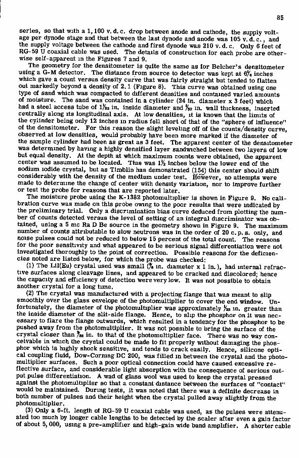
85
s er i e s , so that with a 1,100 v. d. c . drop between anode and cathode, the supply voltage per dynode stage and that between the last dynode and anode was 105 v. d. c . , and the supply voltage between the cathode and f i r s t dynode was 210 v. d. c. Only 6 feet of R G - 5 9 U coaxial cable was used. The details of construction for each probe are otherwise self-apparent in the F igures 7 and 9.
The geometry for the densitometer i s quite the same as for B e l c h e r ' s densitometer using a G - M detector. The distance from source to detector was kept at 6^4 inches which gave a count versus density curve that was fa i r ly straight but tended to flatten out markedly beyond a density of 2.1 (Figure 8). T h i s curve was obtained using one type of sand which was compacted to different densities and contained var ied amounts of moisture. The sand was contained in a cylinder (24 in. diameter x 3 feet) which had a s tee l a c c e s s tube of 1/ 32 in . inside diameter and Jsa m. wa l l thickness, inserted central ly along its longitudinal ax is . At low densities, it i s known that the l imits of the cylinder being only 12 inches in radius f e l l short of that of the "sphere of influence" of the densitometer. F o r this reason the slight leveling off of the counts/density curve , observed at low densities, would probably have been more marked if the diameter of the sample cylinder had been as great a s 3 feet. The apparent center of the densitometer was determined by having a highly densifled layer sandwiched between two l a y e r s of low but equal density. At the depth at which maximum counts were obtained, the apparent center was assumed to be located. T h i s was 1 2 inches below the lower end of the sodium iodide c r y s t a l , but a s T i m b l i n has demonstrated (154) this center should shift considerably with the density of the medium under test. However, no attempts were made to determine the change of center with density variation, nor to improve further or test the probe for reasons that a r e reported later .
The moisture probe using the K-1382 photomultiplier i s shown in F igure 9. No c a l i bration curve was made on this probe owing to the poor resu l t s that were indicated by the pre l iminary t r i a l . Only a discr iminat ion b ias curve deduced f r o m plotting the number of counts detected versus the level of setting of an integral d iscr iminator was obtained, using a 5 mc R a D Be source in the geometry shown in F igure 9, The maximum number of counts attributable to slow neutrons was in the order of 20 c . p, s. only, and noise pulses could not be reduced to below 15 percent of the total count. The reasons for the poor sensitivity and what appeared to be ser ious signal differentiation were not investigated thoroughly to the point of correct ion. Poss ib le reasons for the def ic ienc ies noted are l isted below, for which the probe was checked:
(1) The L i l ( E u ) c r y s t a l used was s m a l l (% in. diameter x 1 i n . ) , had internal r e f r a c tive surfaces along cleavage l ines , and appeared to be cracked and discolored; hence the capacity and efficiency of detection were very low. It was not possible to obtain another c r y s t a l for a long time.
(2) The c r y s t a l was manufactured with a projecting flange that was meant to s l ip smoothly over the glass envelope of the photomultiplier to cover the end window. Unfortunately, the diameter of the photomultiplier was approximately ^32 in, greater than the inside diameter of the s l i t - s ide flange. Hence, to s l ip the phosphor on i t was nece s s a r y to f l a r e the flange outwards, which resulted in a tendency for the phosphor to be pushed away from the photomultiplier. It was not possible to bring the surface of the c r y s t a l c loser than fsi in . to that of the photomultiplier face. T h e r e was no way conceivable in which the c r y s t a l could be made to fit properly without damaging the phosphor which i s highly shock sensitive, and tends to c r a c k easi ly . Hence, s i l icone optic a l coupling f luid, Dow-Corning D C 200, was f i l l e d in between the c r y s t a l and the photomultiplier surfaces . Such a poor optical connection could have caused excess ive r e flective surface , and considerable light absorption with the consequence of serious output pulse differentiation. A wad of g lass wool was used to keep the c r y s t a l pres sed against the photomultiplier so that a constant distance between the surfaces of "contact" would be maintained. During tests, it was noted that there was a definite decrease in both number of pulses and their height when the c r y s t a l pulled away slightly f r o m the photomultiplier,
(3) Only a 6-ft, length of R G - 5 9 U coaxial cable was used, as the pulses were attenuated too much by longer cable lengths to be detected by the s ca l er after even a gain factor of about 5, 000, using a pre -ampl i f i er and high-gain wide band ampli f ier . A shorter cable
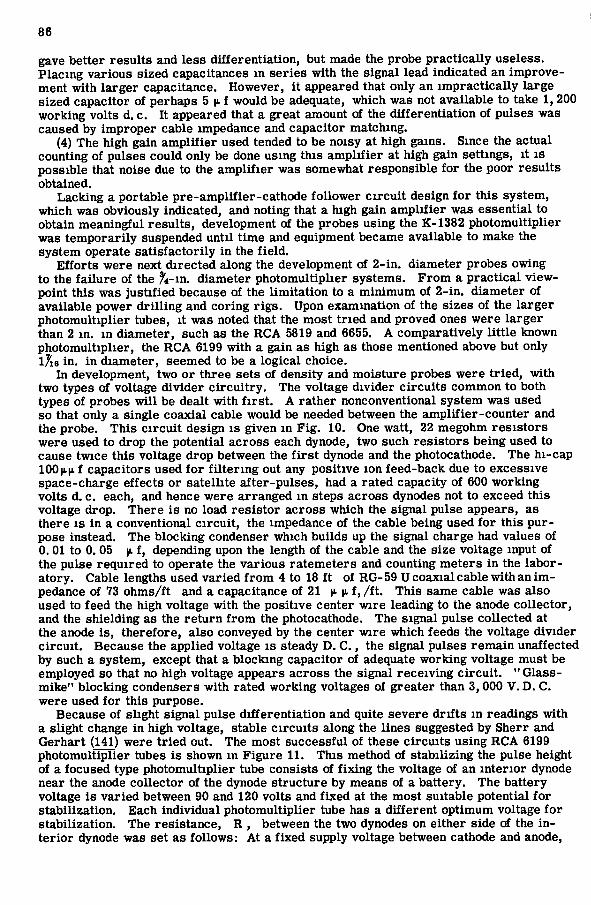
86
gave better resul ts and l e s s differentiation, but made the probe pract ica l ly use less . P lac ing various s ized capacitances m ser i e s with the signal lead indicated an improvement with larger capacitance. However, i t appeared that only an impract icaUy large s ized capacitor of perhaps 5 |». f would be adequate, which was not available to take 1, 200 working volts d. c . It appeared that a great amount of the differentiation of pulses was caused by improper cable impedance and capacitor matching.
(4) The high gain amplif ier used tended to be noisy at high gains. Since the actual counting of pulses could only be done using this amplif ier at high gain settings, it i s possible that noise due to the amplif ier was somewhat responsible for the poor resul ts obtained.
Lacking a portable pre-amplrfier-cathode follower c i rcu i t design for this system, which was obviously indicated, and noting that a high gain ampli f ier was essential to obtain meaningful resul t s , development of the probes using the K-1382 photomultiplier was temporari ly suspended until time and equipment became available to make the system operate sat isfactori ly in the f ie ld.
Ef forts were next directed along the development of 2- in . diameter probes owing to the fa i lure of the ft-m. diameter photomultiplier systems. F r o m a pract ica l viewpoint this was justif ied because of the limitation to a minimum of 2- in . diameter of available power dri l l ing and coring r i g s . Upon examination of the s i zes of the larger photomultiplier tubes, it was noted that the most tr ied and proved ones were larger than 2 m. in diameter, such as the R C A 5819 and 6655. A comparatively little known photomultiplier, the R C A 6199 with a gain as high as those mentioned above but only l7i6 in. in diameter, seemed to be a logical choice.
In development, two or three sets of density and moisture probes were tr ied, with two types of voltage divider c i rcu i t ry . The voltage divider c i rcu i t s common to both types of probes wi l l be dealt with f i r s t . A rather nonconventional system was used so that only a single coaxial cable would be needed between the amplif ier-counter and the probe. T h i s c ircui t design i s given in F i g . 10. One watt, 22 megohm r e s i s t o r s were used to drop the potential a c r o s s each dynode, two such r e s i s t o r s being used to cause twice this voltage drop between the f i r s t dynode and the photocathode. The hi-cap 100 | i | i f capacitors used for f i l ter ing out any positive ion feed-back due to excess ive space-charge effects or satell ite af ter-pulses , had a rated capacity of 600 working volts d. c. each, and hence were arranged in steps a c r o s s dynodes not to exceed this voltage drop. T h e r e i s no load res i s tor a c r o s s which the signal pulse appears, as there i s in a conventional c ircui t , the impedance of the cable being used for this purpose instead. The blocking condenser which builds up the signal charge had values of 0. 01 to 0. 05 |L f, depending upon the length of the cable and the s ize voltage input of the pulse required to operate the various ratemeters and counting meters in the laboratory. Cable lengths used var ied f rom 4 to 18 ft of R G - 5 9 U coaxial cable with an i m pedance of 73 ohms/ft and a capacitance of 21 ^ v f, / f t . T h i s same cable was also used to feed the high voltage with the positive center wire leading to the anode collector, and the shielding as the return from the photocathode. The signal pulse collected at the anode i s , therefore, also conveyed by the center wire which feeds the voltage divider c ircui t . Because the applied voltage i s steady D. C . , the signal pulses remain unaffected by such a system, except that a blocking capacitor of adequate working voltage must be employed so that no high voltage appears a c r o s s the signal receiving c ircui t , " G l a s s -mike" blocking condensers with rated working voltages of greater than 3, 000 V . D. C . were used for this purpose.
Because of slight signal pulse differentiation and quite severe drifts in readings with a slight change in high voltage, stable c i rcu i t s along the l ines suggested by Sherr and Gerhart (141) were tried out. The most successful of these c ircu i t s using R C A 6199 photomultiplier tubes i s shown in F igure 11. T h i s method of stabil izing the pulse height of a focused type photomultiplier tube consists of fixing the voltage of an interior dynode near the anode collector of the dynode structure by means of a battery. The battery voltage i s varied between 90 and 120 volts and fixed at the most suitable potential for stabilization. E a c h individual photomultiplier tube has a different optimum voltage for stabilization. The res is tance , R , between the two dynodes on either side of the i n terior dynode was set as follows: At a fixed supply voltage between cathode and anode.

^ • E - . - O ' 0 . 9 3 0 " I.D.
LUCITE
K - 1382 - I ( 1 ^ 2 ° '
PHOTOMULTIPLIER -
TUBE
0 .905 I.D
4
CHAMBER
—ICM
AMPHENOL TYPE R G - 5 9 U 07 CABLE
3 4 - 4 0 SET SCREWS 8
0 - R I N G GROOVES
VOLTAGE DIVIDER
POTTED BASE SECTION
M U M E T A L . . MAGNETIC SHIELD ^ D.
o
I " 0 . 0 . - i WALL THICKNESS
ALUMINUM TUBING
LITHIUM IODIDE EUROPIUM ACTIVATED CRYSTAL
^4-40M^lc^^^^ ^ ' ^ ' LEAD SHIELD
0 - R I N G GROOVE
- 2 8 SCREW
5M c RADIUM D B E R Y L L I U M SOURCE
4 - 4 0 S E T SCREW
ALUMINUM COVER
Figure 9. S c i n t i l l a t i o n moisture content probe using K-1382 photomultiplier tube, 1 in. i n diameter.
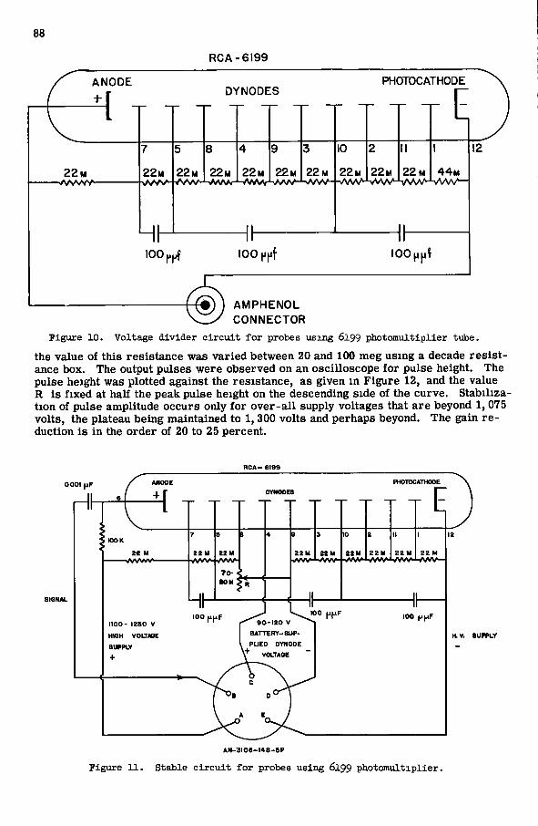
88
R C A - 6 1 9 9
ANODE DYNODES
PHOTOCATHODE
2 2 M
7
22M
5
22 M 22 M
4
2 2 M 22M
3
22 M
10
2 2 M
2
2 2 M
M
22 M 4 4 M
iOOfipf 100 ppf l O O ^ p l
A M P H E N O L CONNECTOR
Figure 10. Voltage divider c i r c u i t for probes using 6199 photomultiplier tube. the value of this res is tance was varied between 20 and 100 meg using a decade r e s i s t ance box. The output pulses were observed on an oscil loscope for pulse height. The pulse height was plotted against the res is tance , as given in F igure 12, and the value R i s fixed at half the peak pulse height on the descending side of the curve. Stabi l ization of pulse amplitude occurs only for o v e r - a l l supply voltages that are beyond 1, 075 volts, the plateau being maintained to 1, 300 volts and perhaps beyond. The gain r e duction i s in the order of 20 to 25 percent.
0001 fxF
100 K Z£ M Z Z M
i / V W ZZ M ZZ M ZZ M Z Z H ZZM
100 puF 9 0 - I Z 0 V
BATTERY-SUP 1100- IZSO V
HK3H VOLTAGE
SUPPLY
+ VOLTASE
K V, SUPPLY
A N - 3 I O e - l 4 S - 5 P
Figure 11. Stable c i r c u i t for probes using 6199 photomultiplier.
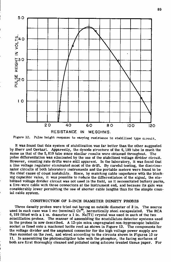
89
2 0 4 0 6 0 8 0 100 120
R E S I S T A N C E IN MEGOHMS. Figure 12. Pulse height response to varying resistance In stabilized type c i r c u i t .
It was found that this system of stabilization was far better than the other suggested by Sherr and Gerhart . Apparently, the dynode structure of the 6,199 tube i s much the same as that of the 5, 819 tube since s imi lar resul ts were obtained throughout. The pulse differentiation was eliminated by the use of the stabil ized voltage divider c ircui t . However, counting rate drifts were s t i l l apparent. In the laboratory, it was found that a line voltage regulator eliminated most of the drift . B y care fu l testing, the d i s c r i m i nator c i rcu i t s of both laboratory instruments and the portable meters were found to be the chief cause of count instability. Since, by matching cable impedance with the blocking capacitor value, it was possible to reduce the differentiation of the signal, the s ta bi l ized voltage divider c ircu i t was not used in the f ield, as it necessitated battery packs, a f ive -wire cable with three connectors at the instrument end, and because its gain was considerably lower permitting the use of shorter cable lengths than for the simple coaxia l cable system.
C O N S T R U C T I O N O F 2 - I N C H D I A M E T E R D E N S I T Y P R O B E S
T h r e e density probes were tr ied out having an outside diameter of 2 in. The source used in each case was 1 mc (nominal) Co*", hermetical ly steel encapsulated. The R C A 6,199 fitted with a 1 m. diameter x 1 in. N a ( T l ) c r y s t a l was used in each of the two scintil lation probes. The manner of assembling the scintil lation detector systems used in the probes i s now described. A 12-pin m i c a impregnated non-hygroscopic bakelite socket i s f ixed onto a machined Incite r e e l as shown in F igure 13. The components for the voltage divider and the amphenol connector for the high voltage power supply are then mounted on the ree l , and wired according to the c ircu i t s shown in F igures 10 or 11. In assembling the photomultiplier tube with the phosphor, the facing surfaces of both a r e f i r s t thoroughly cleaned and polished using si l icone treated tissue paper. F o r
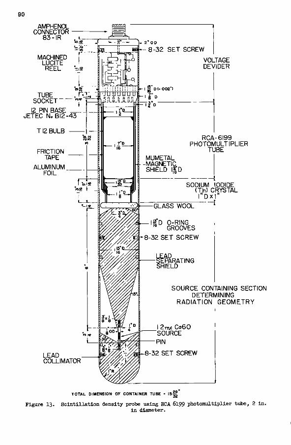
90
AMPHENOL CONNECTOR
83- IR
MACHINED LUCITE
REEL
TUBE SOCKET lOI*
12 PIN BASE JETEC No 612-43
T12 BULB
FRICTION TAPE
ALUMINUM FOIL "
2" OD
LEAD COLLIMATOR
K- 8-32 S E T SCREW
\J- I H" D t- 002")
MUMETAL -MAGNETIC, SHIELD 1,1 D
U U I I I U lU U LI n n 1} n ill n r l J j L i i l - i i _ i l i . l J j l
ft
VOLTAGE DEVIDER
RCA-6199 PHOTOMULTIPLIER
TUBE
-GLASS WOOL
i — I ! I " D O-RING GROOVES
h-8-32 S E T SCREW
-SEPARATING SH ELD
SODIUM IODIDE (Th) CRYSTAL l"Dx|"
- i
SOURCE CONTAINING SECTION DETERMINING
RADIATION GEOMETRY
i 2mc Co60 "SOURCE
B-8-32 SET SCREW
TOTAL DIMENSION OF CONTAINER TUBE = 15| - |
Figure 13 . S c i n t i l l a t i o n density probe using RCA 6199 photomultiplier tube, 2 i n . i n diameter.

91
optical coupling, either white vaseline (petroleum jel ly) or preferably sil icone fluid, Dow-Corning D C - 2 0 0 or any other optical cementing agent, i s applied and spread evenly on both surfaces . The crys ta l i s worked in careful ly avoiding the inclusion of a ir bubbles and pressed as close to the photomultiplier face as possible; the excess f luid i s then wiped off. Aluminum foi l that i s wide enough to cover the c r y s t a l and run up to half the length of the photomultiplier tube i s wrapped closely around the tube and c r y s -
R G - 5 9 U C A B L E
; l | ° A D A P T E R
6 - 3 2 S E T S C R E W
Z ° A D A P T E R 8
6 - 3 2 S E T S C R E W
Z"" 0 - R I N G G R O O V E S 8
I | " D 0 - R I N G G R O O V E S
S P A C E R
L^"" -MACHINED L U C I T E 16
G E I G E R M U E L L E R T U B E T Y P E V r C T O R E E N I B 8 5
Figure l l i . GeiRer-Mueller detector adapted for 2-in. diameter density probe.
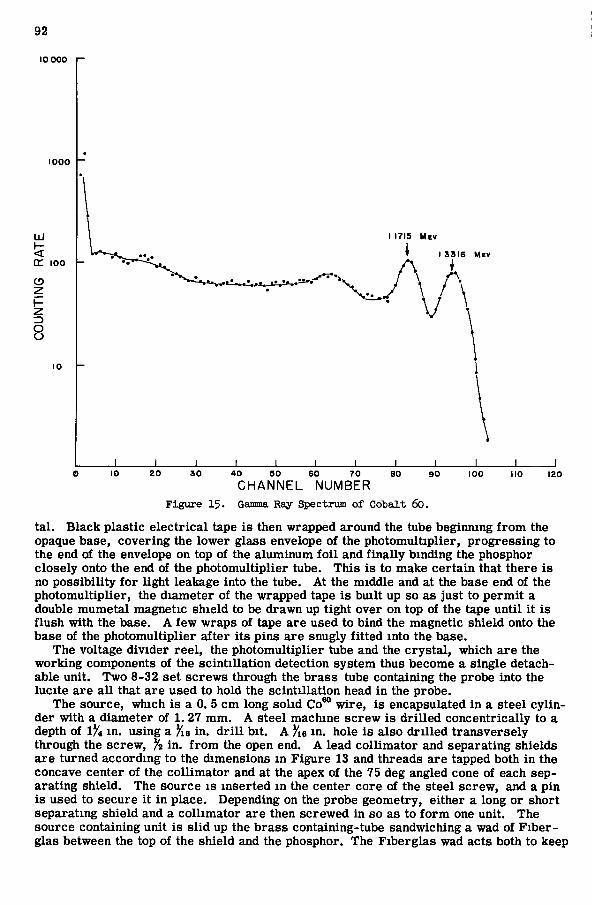
92
10 0 0 0 1 -
1 0 0 0
UJ
OC 1 0 0
( 5
8
1 0
I 1 7 I S M E V
I 3 3 1 6 M E V
_L _L 10 2 0 3 0 8 0 9 0 1 0 0 110
C H A N N E L N U M B E R Figure 15. Gamma Ray Spectrum of Cotalt 6o.
tal . B l a c k plast ic e l ec tr i ca l tape i s then wrapped around the tube beginning f rom the opaque base, covering the lower glass envelope of the photomultiplier, progress ing to the end of the envelope on top of the aluminum foi l and finally binding the phosphor closely onto the end of the photomultiplier tube. T h i s i s to make certa in that there i s no possibil ity for light leakage into the tube. At the middle and at the base end of the photomultiplier, the diameter of the wrapped tape i s built up so as just to permit a double mumetal magnetic shield to be drawn up tight over on top of the tape until it i s f lush with the base. A few wraps of tape are used to bind the magnetic shield onto the base of the photomultiplier after its pins are snugly fitted into the base.
The voltage divider ree l , the photomultiplier tube and the crys ta l , which are the working components of the scintil lation detection system thus become a single detachable unit. Two 8-32 set s c r e w s through the b r a s s tube containing the probe into the lucite are a l l that are used to hold the scintillation head in the probe.
The source, which i s a 0. 5 c m long sol id Co*" wire , i s encapsulated in a steel cy l in der with a diameter of 1. 27 mm. A steel machine s c r e w i s dr i l led concentrically to a depth of 1^4 in. using a Yie in. d r i l l bit. A Jie in. hole i s also dr i l led transverse ly through the screw, % in. from the open end. A lead collimator and separating shields a r e turned according to the dimensions in F igure 13 and threads are tapped both in the concave center of the coll imator and at the apex of the 75 deg angled cone of each separating shield. The source i s inserted in the center core of the steel screw, and a pin i s used to secure it in place. Depending on the probe geometry, either a long or short separating shield and a coll imator are then screwed in so as to form one unit. The source containing unit i s s l id up the b r a s s containing-tube sandwiching a wad of F i b e r -glas between the top of the shield and the phosphor. The F iberg las wad acts both to keep

93
-STEEL DRIVING CAP
, / - ^ RUBBER STOPPER No 11
GROUND SURFACE/
- ^ D. HOLES
' • ^ MASKING TAPE
DESIRED MAXIMUM DEPTH OF MEASUREMENT* 6 0 "
WELD
STEEL POINT
Figure l6. Access tube for ri>.id Licasurements.

94
the phosphor p ressed against the f ace of the p h o t o m u l t i p l l e r and to dampen shocks suf f e r e d by the s c i n t i l l a t i o n head un i t . Set s c rews a re used to keep the source ho ld ing u n i t i n a r i g i d f i x e d geomet ry w i t h respec t to the phosphor de tec tor .
T w o types of densi ty probes us ing s c i n t i l l a t i o n were t r i e d out i n the f i e l d . The only d i f f e r e n c e between these two probes was that whereas the distance between the source and phosphor was 7 i n . i n the e a r l i e r one, as shown i n F i g . 13, i t was only 5?4 i n , i n the l a t t e r . F i g . 14 shows the detector head of a t h i r d p robe , not u s ing s c i n t i l l a t i o n , bu t adapting a 1- in. G e i g e r - M u e l l e r de tec t ion head sys tem f o r the 2 - i n . d i amete r p robe . The source ho ld ing un i t had exac t ly the same shape as f o r the sho r t s c i n t i l l a t i o n p robe w h i c h i s the same shape as f o r the l o n g p robe , but w i t h the separa t ing sh i e ld cut a t the top so that the source to detector distance i s 5^4 i n .
Opera t ion of Dens i ty Probes
The s c i n t i l l a t i o n de tec t ion s y s t e m was v e r y sens i t ive , b e i n g 20 to 40 t i m e s m o r e sens i t ive than the G e i g e r - M u e l l e r sy s t em used. Hence the 1 mc source was unnecess a r i l y l a r g e , 0 . 1 mc be ing m o r e than adequate f o r the purpose at hand. Since the mos t r e l i a b l e equipment was conf ined to the l a b o r a t o r y , s p e c t r a l e m i s s i o n cu rves and p r e l i m i n a r y c a l i b r a t i o n were f i r s t p e r f o r m e d w i t h such equipment . However , the l a b o r a t o r y and equipment had on ly a b i n a r y sca l e r w i t h a scale of 64 wh ich was incapable of r e g i s t e r i n g counts i n excess of 200 cps . A t l o w d i s c r i m i n a t o r se t t ings , the count ing r a t e w i t h the probe i n use was i n excess of 5, 000 cps. Hence, at f i r s t , a g rea t m i s take was made i n t r y i n g to reduce s u f f i c i e n t l y the number of counts detected by r a i s i n g the d i s c r i m i n a t o r l e v e l . A s may be observed f r o m the s p e c t r a l e m i s s i o n of Co*", shown i n F i g . 15, t h i s cou'.d only be accompl i shed by r a i s i n g the l e v e l so h igh as to cu t out a l l pulses beyond that f o r the h igher energy peak of Co*° at 1. 33 M e v . Since only about 3 pe rcen t of the t o t a l detected counts were needed, th i s meant se t t ing the d i s c r i m i n a t o r at the l o w e r end of the steep descent f r o m the 1. 33 M e v . peak. Obvious ly , at t h i s se t t i n g any s l i gh t d r i f t i n the d i s c r i m i n a t o r would give d r a s t i c count v a r i a t i o n . M u c h t i m e and w o r k was wasted u n t i l the cause f o r t h i s d r a s t i c v a r i a b i l i t y was ascer ta ined . T w o sca l e r s w e r e l a t e r used i n s e r i e s , w i t h d i s c r i m i n a t o r se t t ing set l o w i n o r d e r to i n clude m o s t of the s p e c t r a l range of -y - r a y sca t ter i m p i n g i n g on the c r y s t a l . Hence, h igh enough count ing r a t e s cou ld be r e g i s t e r e d so as to have the d i s c r i m i n a t o r set at the r e l a t i v e l y f l a t r e g i o n of the s p e c t r a l de tec t ion c u r v e , where d i s c r i m i n a t o r i n s t a b i l i t y was not h y p e r c r i t i c a l .
The probe , w i t h 7 i n . dis tance separa t ing the source f r o m the detec tor , was designed so as to obta in as deep a sample as poss ib le , yet one which w o u l d also extend the g r ea t est dis tance h o r i z o n t a l l y . A t a densi ty of 1.8 g /cm^, the shape of the sample was e s t i ma ted to be that of a r o t a t i o n e l l i p s o i d w i t h a v e r t i c a l d i ame te r of about 12 i n . and a h o r i z o n t a l d i amete r of about 24 i n . w i t h the apparent center located about i J i i n . f r o m the bo t t om of the phosphor . The probe was s p e c i f i c a l l y designed to meet the exigencies of a p r a c t i c a l job i n wh ich i t was sought to obta in grea tes t accuracy at l o w dens i t ies . The job consis ted of m e a s u r i n g the densi ty and m o i s t u r e content to f i n d the t h e r m a l r e s i s t i v i t y of s o i l under c i t y pavements wh ich w e r e to en t rench h igh tens ion cable l i n e s . The job was p e r f o r m e d i n c o l l a b o r a t i o n w i t h the Publ ic Serv ice Company of New Jersey , whereby th i s probe was thoroughly t r i e d out i n the f i e l d .
C a l i b r a t i o n of the e a r l y 2 - i n . d i ame te r long probe was p e r f o r m e d as f o l l o w s : Sand was wet ted and dens i t i ed to d i f f e r e n t degrees m an a l u m i n u m c y l i n d e r (3 f t . i n d i ame te r and 4 f t . high) i n l a y e r s not less than 1 f t . deep. The center was then augered out and a s tee l access pipe (2^ie i n . outside d i ame te r and Xe i n , t h i ck ) i n s e r t e d w h i c h was capped at the bo t t om end. The d imens ions and cons t ruc t i on of the access pipe a re shown i n F i g . 16. The c a l i b r a t i o n c y l i n d e r as used d u r i n g c a l i b r a t i o n i s d r a w n i n F i g . 17. I m med ia t e ly a f t e r the access tube was i n s e r t e d , readings w e r e made both f o r the dens i ty and m o i s t u r e content u s ing the 2 - i n . d i amete r p robes . When the l a b o r a t o r y equipment was used, two one-minute -abso lu te -count read ings were made us ing an e l e c t r i c e lapsed-t i m e t i m e r , f o r each depth f o r each probe . Depth i n t e r v a l s at w h i c h read ings were taken w e r e 3 i n . d u r i n g a l l c a l i b r a t i o n w o r k .
Upon cessa t ion of readings by the nuclear m e t e r s , a Co i l e - type co re s ample r equipped w i t h a d r o p h a m m e r was used to take two o r th ree und is tu rbed 3 - i n . d i ame te r x 3 - i n .
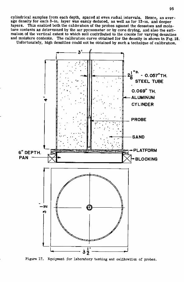
95
c y l i n d r i c a l samples f r o m each depth, spaced at even r a d i a l i n t e r v a l s . Hence, an a v e r age densi ty f o r each 3 - i n . l aye r was eas i ly deduced, as w e l l as f o r 1 2 - i n . and deeper l a y e r s . T h i s enabled both the c a l i b r a t i o n of the probes against the densi t ies and m o i s t u r e contents as de t e rmined by the a i r pycnometer o r by c o r e d r y i n g , and also the e s t i m a t i o n of the v e r t i c a l extent to wh ich s o i l con t r ibu ted to the counts f o r v a r y i n g densi t ies and m o i s t u r e contents. The c a l i b r a t i o n cu rve obtained f o r the densi ty i s shown i n F i g . 18.
Unfor tuna te ly , h igh densi t ies cou ld not be obtained by such a technique of c a l i b r a t i o n .
3 -
6" D E P T H . PAN
S T E E L T U B E C O S T ' T H .
0 . 0 6 9 " TH.
ALUMINUM
C Y L I N D E R
P R O B E
S A N D
J — P L A T F O R M
B L O C K I N G
Figure 17. Equipment for laboratory testing and calibration of probes.
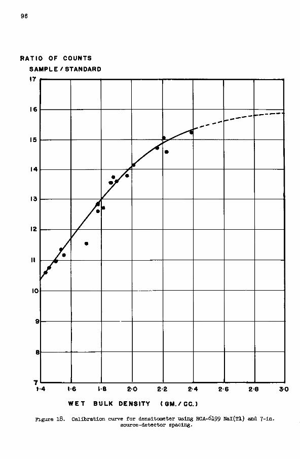
96
RATIO OF COUNTS
S A M P L E / S T A N D A R D
17
1-6 1-8 2 0 2-2 2-4
W E T B U L K D E N S I T Y ( 6 M . / C C . )
2-6 2-8 3 0
Figure l8. Calibration curve for densitometer using RCA-6199 Nal(Tl) and 7-in. source-detector spacing.
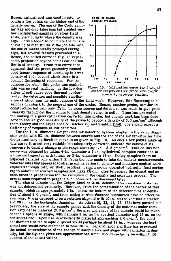
97
Hence, na tu r a l s o i l was used i n s i t u , to obta in a f e w points on the higher end of the densi ty c u r v e . The use of the Coi le sampl e r was not only l abor ious but y i e lded v e r y f e w undis tu rbed samples on stony f i e l d so i l s , p a r t i c u l a r l y where the densi ty was h igh . I t was hoped to complete the densi ty cu rve up to h igh l i m i t s at the job s i te w i t h the use of mechamca l ly power.ed c o r i n g r i g s , but s e v e r a l f a c t o r s prevented t h i s . Hence, the dotted cu rve i n F i g . 18 r e p r e sents p r o j e c t i o n beyond ac tual c a l i b r a t i o n l i m i t s of dens i ty . F r o m th i s cu rve i t i s apparent that the probe geomet ry caused good l i n e a r response of counts up to a wet densi ty of 2. 0, beyond which there i s a decided f l a t t e n i n g of response. F o r the purpose f o r wh ich th i s probe was appl ied , t h i s was no r e a l handicap, as the l o w dens i t i e s of s o i l cause poor t h e r m a l conduct i v i t y , the de tec t ion and poss ib le a m e l i o r -
R A T I O O F C O U N T S S A M P L E / S T A N D A R D
I 2
W E T D E N S I T Y
Figure 19. Calibration curve for 2-in. diameter Geiger-Mueller probe with 5-3/'t"
source to detector spacing. a t ion of which was the m a i n purpose of the f i e l d w o r k . However , th i s f l a t t e n i n g i s a se r ious drawback to the genera l use of the p robe . Hence, another p robe , s i m i l a r i n cons t ruc t ion but w i t h only 5^4 i n . between source and de tec tor , was made to g ive good l i n e a r i t y throughout the m e d i u m to high densi ty range i n s o i l s . T i m e has prevented the m a k i n g of a good c a l i b r a t i o n cu rve f o r th i s probe , but enough w o r k has been done here to assure good s e n s i t i v i t y of the probe to beyond a densi ty of 3. 0 g m / c m * al though f r o m theory and the exper ience of Be l che r (9) and T i m b l i n (154), one should expect a f l a t t e n i n g of response at l ow dens i t ies .
F o r the 1- in. d i ame te r G e i g e r - M u e l l e r detect ion sys t em adapted to the 2 - i n . d i a m eter probe w i t h 5^4- in . distance between source and the end of the G e i g e r - M u e l l e r tube, the p r e l i m i n a r y c a l i b r a t i o n cu rve i s as g iven i n F i g . 19. A s only a f e w points make up th i s cu rve i t i s not v e r y r e l i a b l e but adequately serves to indica te the nature of i t s response to densi ty change m the range c o v e r i n g 1. 4 - 2. 2 g m / r m * . T h i s c a l i b r a t i o n cu rve was obtained by t ak ing 4 - i n . d i amete r x 6 - i n . c y l i n d r i c a l samples contained i n a t h i n - w a l l sample r w i t h l i n i n g , o r 3 - i n . d i amete r x 1 6 - i n . Shelby samples f r o m an adjacent p a r a l l e l hole w i t h i n 3 f t . f r o m the hole made to take the nuclear measurements . Selected s i tes that appeared to o f f e r great v a r i a t i o n i n densi ty and m o i s t u r e content were e : ^ l o r e d th rough 6 - f t . o r 1 0 - f t . p r o f i l e s , u s ing a m o t o r - o p e r a t e d h y d r a u l i c - f e e d c o r i n g r i g to ob ta in und i s tu rbed samples and make 2 f8 - in . holes to r ece ive the c losed-end access tubes i n p r e p a r a t i o n f o r the r ecep t ion of the densi ty and m o i s t u r e probes . The precaut ions r e q u i r e d to p r epa re such holes w i l l be d iscussed l a t e r .
The s ize of sample that the G e i g e r - M u e l l e r 2 - i n . dens i tometer r e so lves i n i t s use was not de t e rmined p r e c i s e l y . However , f r o m the de t e rmina t i on of the center of t h i s sample , wh ich i s app rox ima te ly 1 i n . be low the bo t tom of the detector tube at d e n s i t i e s of about 2. 0 g /cm*, and f r o m not ing at what distance boundar ies have no e f f e c t on readings , i t was deduced to be a r o t a t i o n e l i p s o i d w i t h 10 . in . as the v e r t i c a l d i ame te r and 20 i n . as the h o r i z o n t a l d i ame te r . A s o thers (9, 33, 4 1 , 76, 154) have poin ted out p r e v i o u s l y , the s ize of the sample v a r i e s w i t h the densi ty of the m a t e r i a l under tes t . F o r v e r y dense m a t e r i a l (3. 0 g /cm*) , the s ize and shape of the sample would be much neare r a sphere i n shape, w i t h perhaps 8 i n . as the v e r t i c a l d i amete r and 12 i n . as the h o r i z o n t a l one. Upon use i n l ow-dens i t y m a t e r i a l approaching 1 . 0 g / c m ^ the v e r t i c a l d i ame te r of the sample e l i p s o i d wou ld perhaps be about 12 i n . , whereas the h o r i zonta l one would have s t re tched to near 28 i n . L a c k of labor and t i m e has p reven ted the ac tua l d e t e r m i n a t i o n of the change of sample s ize and shape w i t h v a r i a t i o n i n dens i t y , but the f i g u r e s g iven a re approx imat ions which should c e r t a i n l y be w i t h i n ± 10 percent of the ac tua l values.
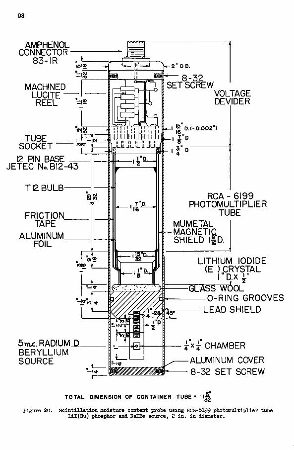
98
AMPHENOL CONNECTOR
83-IR
MACHINED LUCITE REEL
TUBE SOCKET 12 PIN BASE
L
JETEC No. B12-43
TI2 BULB-lO
FRICTION TAPE
ALUMINUM FOIL
5wtc. RADIUM_D. BERYLLIUM SOURCE
UUlUUl iJUlJ i-i n n n * n li
t t—I 11 D.( -0 .002")
1
, 7"D.
h i - 2 " 0 D.
SET%CR EW VOLTAGE DEVIDER
1 1 D '
RCA - 6199 PHOTOMULTIPLIER
TUBE MUMETAL MAGNETIC SHIELD l|D.
LITHIUM IODIDE (E ) pRYSTAL
l "D .x
-GLASS WOOL 0-RlNG GROOVES
LEAD SHIELD
i x ^ CHAMBER -ALUMINUM COVER - 8-32 SET SCREW
TOTAL DIMENSION OF CONTAINER TUBE • 1 1 ^ '
Figure 20. S c i n t i l l a t i o n moisture content prote using RCS-6199 photaaultiplier tuTje L l l ( E u ) phosphor and Ralffie source, 2 i n . i n diameter.

99
A p p r a i s a l of 2 - i n . D i a m e t e r Dens i ty Probes
The sens i t iv i ty -o f the 1-in. d i amete r x 1-in. N a l ( T l ) c r y s t a l and RCA-6199 de tec t ion sys t em was about 25 t i m e s that of the G e i g e r - M u e l l e r p robe . Hence, a sy s t em us ing the th innest N a l ( T l ) phosphor ava i lab le and a Co'" source of v e r y l o w in tens i ty , such as 0 . 1 m c , wou ld s t i l l y i e l d a g rea te r number of counts than the G - M sys t em. F r o m the v iewpoin t of u m v e r s a l use, t h i s i s a grea t asset as i t wou ld v i r t u a l l y e l i m i n a t e the r a d i a t i o n hazard . The s c i n t i l l a t i o n probe cou ld cost as l i t t l e as $85 .00 compet ing w e l l w i t h the v e r y l o w cost of $40. 00 f o r the p a r t s f o r a G - M probe .
I n opera t ion , the probe us ing the source-de tec tor distance of 7 i n . i s d e f i n i t e l y l a c k i n g i n s e n s i t i v i t y at h igh densi t ies , and i s not r ecommended f o r gene ra l use. The Geiger-M u e l l e r p robe , a l ready t r i e d out f o r over a thousand de te rmina t ions i n the f i e l d , g ives good l i n e a r response throughout the densi ty range l i k e l y to be encountered i n s o i l t e s t ing . Owing to i t s l o w s e n s i t i v i t y , the p robe gives a r e ad ing e r r o r of about 1.0 percen t owing to s t a t i s t i c a l count ing of r andom counts over one minu te . I t was found that p r o b ably due to h u m i d i t y and t empera tu re change d u r i n g p ro longed use, the s e n s i t i v i t y of the probe would v a r y as much as 25 percen t . I n use w i t h the UAC 522 the accuracy that wou ld be expected f o r densi ty de t e rmina t ions i s ^ 1.5 percent . The even s i zed pulses f r o m a G - M tube, and the b r o a d counts ve r sus h igh vol tage pla teau, makes i t unnecessa ry f o r the G - M detec t ion sys t em to use a p r e c i s i o n me te r w i t h d i s c r i m i n a t o r , and a h igh ly regu la ted h igh vol tage supply, r e d u c i n g both the necess i ty f o r c o m p l i c a t e d e lec t r o n i c c i r c u i t r y and the cost f o r m e t e r s .
W i t h respec t to l i n e a r i t y of response throughout the densi ty range, there i s no reason why the s c i n t i l l a t i o n densi ty probe w i t h the source -de tec to r distance of 5 4 i n . should not be much the same as the G e i g e r - M u e l l e r sy s t em w i t h the same spacing. T h e r e a re ,
RATIO OF COUNTS SAMPL
0-70
0-60
0-50
0-40
E / S T D
0 3 0
0-20
0-10
O 10 20 30 40 SO 60 70 80 PERCENT MOISTURE ON VOLUME BASIS (CC OF WATER / CC OF SOIL)
Figure 21. Calibration curve for hygrometer using RCA-6199, L i l ( E u ) and 5 mc RaDBe source.

100
however , s t i l l c e r t a i n p r o b l e m s inherent m s c i n t i l l a t i o n detect ion, of y photons i n p a r t i c u l a r , that makes i t po ten t i a l ly a less accurate sys tem, unless h igh ly stable e lect r o n i c a m p l i f i c a t i o n and count ing sys tems a re made avai lable f o r f i e l d use. The f i r s t f a c t to be recogn ized i s that because the s ca t t e r ing type s ingle p robe dens i tometer w o r k s on Compton sca t te r , the energies of sca t te red v photons would cover an e n t i r e range s t a r t i n g at 1. 06 Mev , down to 0 f o r a Co*° source . Because of the l i nea r response of in t ens i ty of i l l u m i n a t i o n to the energy of the 7 photon absorbed by a N a l ( T l ) phosphor, there wou ld be a continuous spread i n the ampl i tude of pulses as p i c k e d up, a m p l i f i e d
800 NUMBER OF COUNTS
>
)
^ T O T A L C O U N T
THEf NEUTR
! M A L \
5NSy\
N O I S I
•1 10 20 3 0 4 0 50 6 0
DISCRIMINATOR L E V E L IN VOLTS Figure 22. Discrimination bias curve for L i l (Eu) phosphor, RCA-6199 Probe.
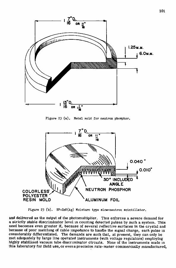
101
25M.M
6.0M.M
16 OR .1
Figure 23 ( a ) . Metal mold for neutron phosphor.
COLORLESSr POLYESTER RESIN MOLD
0 . 0 4 0
0 .010
30* INCLUDED AWGLE
NEUTRON PHOSPHOR
ALUMINUM FOIL Figure 23 (b). BP-ZnS(Ag) Moisture type slow-neutron s c i n t i l l a t o r .
and de l i ve r ed as the output of the p h o t o m u l t i p l l e r . T h i s enforces a severe demand f o r a s t r i c t l y stable d i s c r i m i n a t o r l e v e l i n count ing detected pulses by such a sys t em. T h i s need becomes even grea ter i f , because of s e v e r a l r e f l e c t i v e sur faces i n the c r y s t a l and because of poor ma tch ing of cable impedance to handle the s ignal charge, each pulse i s cons iderab ly d i f f e r e n t i a t e d . The demands are such that, at present , they can only be me t adequately by l a r g e l ine operated i n s t rumen t s (wi th vol tage r egu la to r s ) employ ing h igh ly s t ab i l i zed vacuum tube d i s c r i m i n a t o r c i r c u i t s . None of the i n s t rumen t s made i n t h i s l a b o r a t o r y f o r f i e l d use, o r even a p r e c i s i o n r a t e - m e t e r c o m m e r c i a l l y manufac tu red .
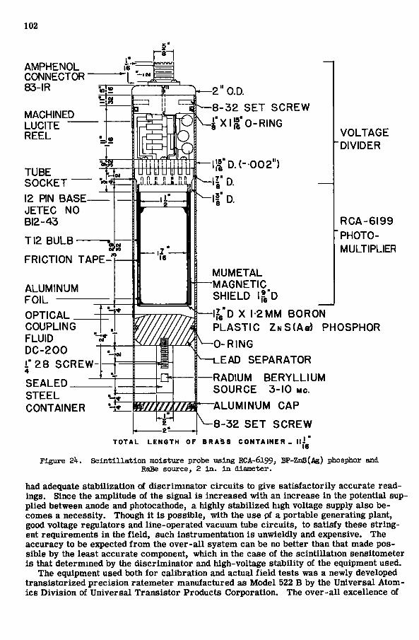
102
ri n n n i» n n U . L L J l L J i . J l . i L l
AMPHENOL CONNECTOR 83-IR
MACHINED LUCITE REEL
TUBE SOCKET 12 RN BASE JETEC NO BI2-43
TI2 BULB
FRICTION TAPE-
ALUMINUM FOIL OPTICAL COUPLING FLUID DC-200 i"28 SCREW 4 SEALED STEEL CONTAINER
2"0.D. 8-32 SET SCREW
Xll-»"0-RING
h - l l iD . ( - 002" )
MUMETAL MAGNETIC SHIELD 9"r
V O L T A G E DIVIDER
R C A - 6 1 9 9 PHOTOMULTIPLIER
16 "
\J^'D X 1-2 MM BORON P L A S T I C Z N S ( A » ) PHOSPHOR
0 - R I N G
L E A D S E P A R A T O R
RADIUM B E R Y L L I U M S O U R C E 3-10 MC.
: teSMZ^—ALUMINUM C A P -8-32 S E T S C R E W
TOTAL LENGTH OF BRA^S CONTAINE R - l l l ^ '
Figure 2k. S c i n t i l l a t i o n moisture probe using RCA-6199, BP-ZnS(Ag) phosphor and RaBe source, 2 i n . i n diameter.
had adequate s t a b i l i z a t i o n of d i s c r i m i n a t o r c i r c u i t s to give s a t i s f a c t o r i l y accurate r e a d ings . Since the ampl i tude of the s igna l i s i nc reased w i t h an increase i n the po ten t i a l supp l i e d between anode and photocathode, a h igh ly s t ab i l i z ed h igh vol tage supply also becomes a necessi ty . Though i t i s poss ib le , w i t h the use pf a por tab le genera t ing p lan t , good vol tage r egu l a to r s and l i n e - o p e r a t e d vacuum tube c i r c u i t s , to s a t i s f y these s t r i n g ent r e q u i r e m e n t s i n the f i e l d , such i n s t r u m e n t a t i o n i s unwie ld ly and expensive. The accuracy to be expected f r o m the o v e r - a l l s y s t e m can be no be t te r than that made p o s s ib le by the leas t accura te component, wh ich i n the case of the s c i n t i l l a t i o n sens i tometer i s that de t e rmined by the d i s c r i m i n a t o r and h igh-vo l tage s t a b i l i t y of the equipment used.
The equipment used both f o r c a l i b r a t i o n and ac tual f i e l d tes ts was a newly developed t r a n s i s t o r i z e d p r e c i s i o n r a t eme te r manufac tu red as M o d e l 522 B by the U n i v e r s a l A t o m i c s D i v i s i o n of U n i v e r s a l T r a n s i s t o r P roduc t s C o r p o r a t i o n . The o v e r - a l l excel lence of

103
this very light ( lOji lb) portable instrument which has features such as a well regulated transis tor ized power supply capable of varying the voltage f rom 800 - 1, 300 v. d. c . , an 11-transistor amplif ier , a discriminator c ircui t , 6 ranges covering 0 - 10, 000 cps, an osci l lator operating at 1, 500 cps for calibrating the instrument internally, four time constants (1 second, 5 seconds, 20 seconds and 120 seconds), and an accuracy of ± 2 percent at ful l scale deflection, made it the selected choice for use in the f ield. An app r a i s a l of the functioning of this meter i s dealt with later. It i s sufficient to report here that the meter lacked adequate discriminator stability and was also somewhat deficient in high voltage stability, part icularly at temperatures above 85 or 90 deg F . The a c curacy obtained with the use of this meter in over 1, 000 determinations averaged about ± 5 percent over the entire range of densities encountered on the f ie ld when employed with the scintillation type densitometer. With the Geiger-Muel ler probe, density could be determined with an accuracy approaching ± 1.5 percent. The instability of the d i s criminator level and that of the high voltage supply s carce ly affects the G - M system as a constant amplitude pulse i s produced along the broad high voltage plateau beyond the Geiger threshold level of the tube.
Design of 2- in. Diameter Moisture Probes
F i g . 20 shows the ear l i er model of the 2-in. diameter moisture probe. The sc int i l lation detection head i s assembled m the same manner as described for that used in the densitometer. The only difference i s that a 1-in. diameter x ^a-in. L i I ( E u ) c r y s t a l i s used instead of the N a l ( T l ) phosphor. It would have been preferable to have used a 1-in. diameter x 1-in. L i l ( E u ) phosphor but at the time of need this s ize was not procurable. The geometry arr ived at f i r s t , shown in F i g . 20, was a compromise between greatest efficiency and greatest sample s ize . Owing to a fa ir ly high rate of 7 emiss ion from the 5 mc RaDBe source used, and a considerable sensitivity of the L i l ( E u ) phosphor to •y phot9ns, the 1-in. lead shield was found necessary to reduce the background count. A s has been previously discussed in the theory of the moisture probe utilizing the ther-maliz ing of fast neutrons, the source to detector distance should not exceed 15 cms at the greatest distance of the sensitive portion of the detector from the source. T h i s i m posed the maximum l imit for the distance between source and detector. The source was tr ied at distances of 15 cms to 5 c m s f rom the farthest end of the L i l ( E u ) c rys ta l , while the probe was immersed m a bucket of paraff in with a 2- in. hole in its center for its reception. The source to detector distance which was decided upon for the probe was 8. 0 c m . (from the farther end of the phosphor). T h i s was fixed as such because there was an attempt to increase the s ize of sample to be more in keeping with that of the density measurement. However, the greater the source to detector distance, the l e s s accurate were the readings owing to the lower count rates part icular ly for dry so i l s . The distance decided upon would give stat ist ical accurac ies of 1-min. readings of approximately ± 1 . 5 percent at a moisture content of 5 percent by volume, and about ± 0. 9 percent for 100 percent water owing to the random nature of radioactive emiss ion alone. A larger source or a larger phosphor could possibly have permitted a ful l 15 c m source to detector geometry which would have given the greatest depth of ver t i ca l resolution of which the instrument i s theoretically capable. The assembly of the mois ture probe is self-evident from F i g . 20. Because of the sensitivity of L i I ( E u ) to y photons, a low y emiss ion rate 5 mc R a D B e source had to be used for the fast neutron source. The source i s contained in a hermetical ly sealed cylinder J i - i n . diameter by 1 in.
The s ize of sample of water that this probe measures was found to be l e s s than a l O - m . diameter sphere with the center approximately at the bottom of the c r y s t a l . In a i r - d r y sand the s i ze of sample was about 16 in. in depth and about 24 in. in diameter,, with its center being approximately 1 m. below the bottom of the L i l ( E u ) phosphor. F igure 21 gives the calibration curve for this probe.
The spectral detection curve, as determined by plotting the counting rate against the leve l of d iscr iminator bias , gives important information which must be obtained so that the level , at which the discriminator i s fixed, i s judiciously selected to give maximum accuracy and stability. F i g . 22 shows the discrimination bias curve of the L i l ( E u )
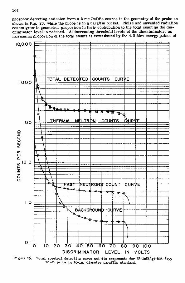
104
phosphor de tec t ing e m i s s i o n f r o m a 5 mc RaDBe source i n the geomet ry of the probe as shown i n F i g . 20, w h i l e the probe i s i n a p a r a f f i n bucket. Noise and unwanted r a d i a t i o n counts g row i n geomet r ic p r o p o r t i o n i n t h e i r c o n t r i b u t i o n to the t o t a l count as the d i s c r i m i n a t o r l e v e l i s reduced. A t i n c r e a s i n g th re sho ld l eve l s of the d i s c r i m i n a t o r , an i nc r ea s ing p r o p o r t i o n of the t o t a l counts i s con t r ibu ted by the 4 .8 M e v energy pulses of
1 0 0 0
1 0 0
o o UJ C/) Q : UJ Q .
V)
Z
O o
10 0
0 1
T O T / iL Dl : T E C F E D G O U sITS C U R / E
f-H F? 1
T H "RMA
' n !
1 NF IJTR
! a 1
•)N "OUN T S \\iR\ 'F
\ \ V \
^ST NEU1 RONS ) COI J N T C U R ' /E
( \ c
\ < ^ K G R O U N r-t;t ttvtr
i
1
10 2 0 3 0 4 0 5 0 6 0 7 0 8 0 9 0 1 0 0
D I S C R I M I N A T O R L E V E L IN V O L T S
Figure 2?, Total spectral detection curve and i t s components for BP-ZnS(Ag)-RCA-6199 moxst probe i n lO-in. diameter paraffin standard.
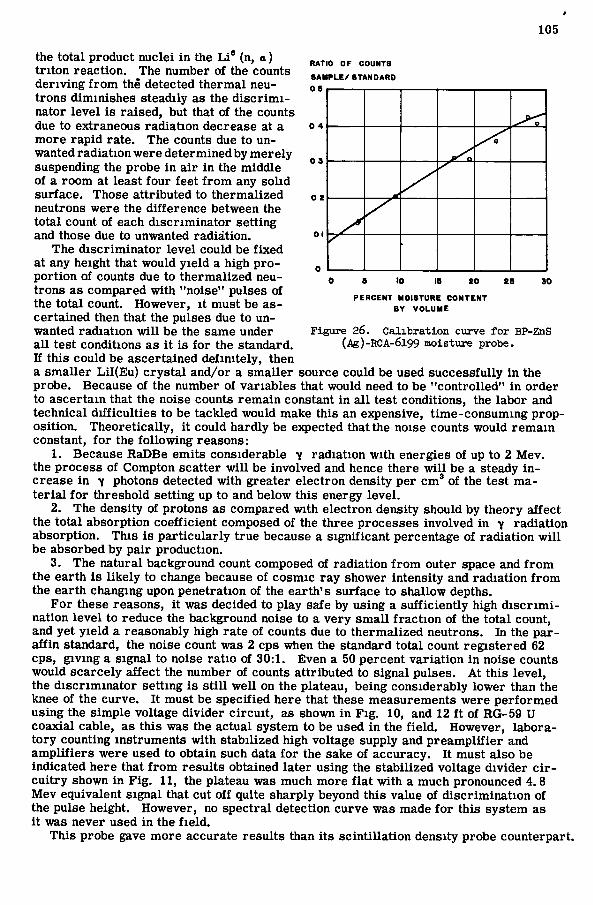
105
R A T I O O F C O U N T S
S A M P L E / S T A N D A R D
0 4
P E R C E N T M O I S T U R E C O N T E N T B Y V O L U M E
Figure 26. Calibration ciirve for BP-ZnS (Ag)-RCA-6l99 moisture probe.
the t o t a l p roduc t nuc le i i n the L i * (n, a ) t r i t o n r e a c t i o n . The number of the counts d e r i v i n g f r o m the detected t h e r m a l neut r o n s d imin i shes s tead i ly as the d i s c r i m i nator l e v e l i s r a i s e d , but that of the counts due to extraneous r a d i a t i o n decrease at a m o r e r a p i d r a t e . The counts due to un wanted r a d i a t i o n were de t e rmined by m e r e l y suspending the probe i n a i r i n the m i d d l e of a r o o m at least f o u r f ee t f r o m any s o l i d su r face . Those a t t r i b u t e d to t h e r m a l i z e d neutrons were the d i f f e r e n c e between the t o t a l count of each d i s c r i m i n a t o r se t t ing and those due to unwanted r a d i a t i o n .
The d i s c r i m i n a t o r l e v e l cou ld be f i x e d at any height that w o u l d y i e l d a h igh p r o p o r t i o n of counts due to t h e r m a l i z e d neut r o n s as c o m p a r e d w i t h "no i se" pulses of the t o t a l count. However , i t mus t be asce r t a ined then that the pulses due to u n wanted r a d i a t i o n w i l l be the same under a l l tes t condi t ions as i t i s f o r the s tandard . K t h i s cou ld be ascer ta ined d e f i n i t e l y , then a s m a l l e r L i l ( E u ) c r y s t a l and /o r a s m a l l e r source cou ld be used succes s fu l l y i n the p robe . Because of the number of va r i ab l e s that would need to be " c o n t r o l l e d " i n o r d e r to a s c e r t a i n tha t the noise counts r e m a i n constant i n a l l t e s t condi t ions , the l abo r and t echn ica l d i f f i c u l t i e s to be t ack led would make th is an expensive, t i m e - c o n s u m i n g p r o p o s i t i o n . T h e o r e t i c a l l y , i t cou ld ha rd ly be expected that the noise counts would r e m a i n constant, f o r the f o l l o w i n g reasons :
1. Because RaDBe e m i t s cons iderable 7 r a d i a t i o n w i t h energies of up to 2 M e v . the p rocess of Compton sca t ter w i l l be invo lved and hence there w i l l be a steady i n crease i n -y photons detected w i t h g rea te r e l e c t r o n densi ty per c m ' of the tes t m a t e r i a l f o r t h r e s h o l d se t t ing up t o and be low t h i s energy l e v e l .
2. The densi ty of p ro tons as compared w i t h e l e c t r o n densi ty should by t heo ry a f f e c t the t o t a l absorp t ion c o e f f i c i e n t composed of the th ree processes i nvo lved i n y r a d i a t i o n absorp t ion . T h i s i s p a r t i c u l a r l y t rue because a s i g n i f i c a n t percentage of r a d i a t i o n w i l l be absorbed by p a i r p roduc t ion .
3. The na tu r a l background count composed of r a d i a t i o n f r o m outer space and f r o m the ea r th i s l i k e l y to change because of cosmic r a y shower in tens i ty and r a d i a t i o n f r o m the e a r t h changing upon pene t r a t ion of the e a r t h ' s su r f ace to sha l low depths.
F o r these reasons, i t was decided to p lay safe by us ing a s u f f i c i e n t l y high d i s c r i m i na t ion l e v e l to reduce the background noise to a v e r y s m a l l f r a c t i o n of the t o t a l count, and yet y i e l d a reasonably h igh r a t e of counts due to t h e r m a l i z e d neut rons . I n the p a r a f f i n s tandard , the noise count was 2 cps when the s tandard t o t a l count r e g i s t e r e d 62 cps, g i v i n g a s igna l to noise r a t i o of 3 0 : 1 . Even a 50 pe rcen t v a r i a t i o n i n noise counts wou ld s c a r c e l y a f f e c t the number of counts a t t r i b u t e d to s igna l pu lses . A t t h i s l e v e l , the d i s c r i m i n a t o r se t t ing i s s t i l l w e l l on the p la teau , be ing cons ide rab ly l o w e r than the knee of the c u r v e . I t mus t be s p e c i f i e d here that these measurements were p e r f o r m e d us ing the s i m p l e vol tage d i v i d e r c i r c u i t , as shown i n F i g . 10, and 12 f t of RG-59 U coax ia l cable , as t h i s was the ac tua l sys tem to be used i n the f i e l d . However , l a b o r a t o r y count ing i n s t rumen t s w i t h s t ab i l i z ed h igh vol tage supply and p r e a m p l i f i e r and a m p l i f i e r s we re used to ob ta in such data f o r the sake of accuracy . I t mus t a lso be ind ica ted here that f r o m r e s u l t s obtained l a t e r us ing the s t ab i l i z ed vol tage d i v i d e r c i r c u i t r y shown i n F i g . 1 1 , the plateau was much m o r e f l a t w i t h a much pronounced 4 .8 M e v equivalent s igna l that cu t o f f quite sha rp ly beyond t h i s value of d i s c r i m i n a t i o n of the pulse height . However , no s p e c t r a l de tec t ion cu rve was made f o r t h i s sys t em as i t was never used i n the f i e l d .
T h i s probe gave m o r e accura te r e s u l t s than i t s s c i n t i l l a t i o n dens i ty probe coun te rpa r t .
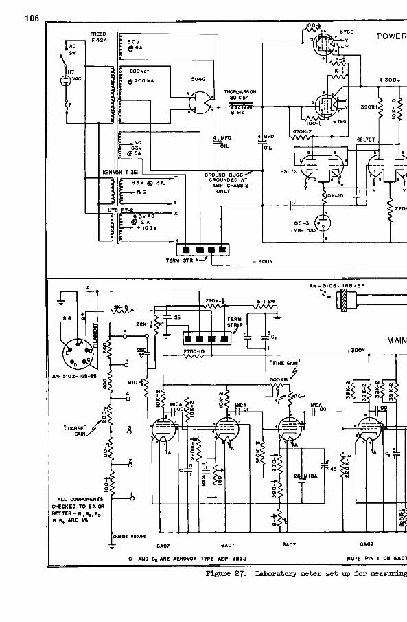
106
FREED F 4 2 4 5 0 v
800 vcT
^ H O 6 3 v
KENYON T-351
—5ir 6 3 v 0 3A.
N.CL
; 6 3 v A C : @ I 2 A : — • + I 0 5 v
1
THORDARSON 20 C 5 4
B Hi.
UFO.
OIL
BROUND B U S S - ^ GROUNDED AT
AMP CHASSIS ONLY
TERM S T R I P -
4TOK-2 MFD I W W
r V W T
POWER
100-^
OK- IO
O C - 3 ^• ( V R - 1 0 5 )
A N - 3 1 0 6 - I 6 S - 8 P
2 7 0 K - t
S T R I P
MAN + 300V 2750-10
V W V R N E GA N
k N - 3 I O Z - l 6 S - 8 S 5 0 0 A B
470-
MICA
ALL COMPONENTS CHECKED TO 5 « OR B E T T E R - R | , R „ R , , a R, A R E IX
6AC7 6A07
C, AND Ct ARE AEROVOX T Y P E A E P 2 2 2 0
6AC7 6AC7
NOTE PIN I ON 6 A C 1
Figure 27. Laboratory meter set up for measuring
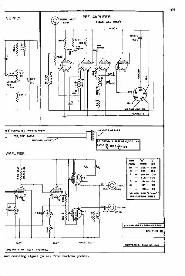
SUPPLY
^SOK IM-I < WW
VOLTAGI
SDA
MFD
OIL
@SIGNAL INPUT 8 3 - I R
PRE-AMPLIFIER T U B E S - / k L L SAKB 's
+ I 0 0 »
10 MFD
«ov-30K-I
sop
N C I
AN -3102- l ee -BP
nLAMENTS
IN V C O N N E C T E D WITH R G - S 9 I U
P R E - A M P C A B L E
SHIELDED J A C K E T '
A N - 3 I 0 6 - I 6 S - B S
T O OBTAIN A GAIN O F 1 0 , 0 0 0 T H E
105 RATIO 0 6 - i _ « • R.
AMPLIFIER
GAG7 6 A C 7
AND PIN 3 ON 6 A S 7 GROUNDED
OUTPUT
B 3 - R
T I M E • R ' f OHMS fl> F
10 — Z O K — 6 0 0 5 — 2 0 K — 2 5 0
i — 2 0 K — 1 0 0 1 — 1 O K — 1 0 0
s — S K — 1 0 0
.2 — 2 K — 1 0 0
1 — 2 K — 5 0
V A L U E S F O R " R ' A N D V FOR C L I P P I N G T I M E S
501 A M P L I F I E R - PRE-AMP A P S
W T . 7 -26-491
6 A C 7 - 6A07 E t f C T R O N I C SHOP NO 1046
and comtlng signal pulses from various probes.
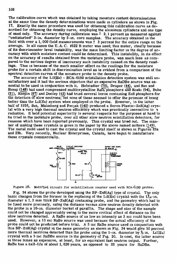
108
The c a l i b r a t i o n c u r v e wh ich was obtained by t a k i n g m o i s t u r e content de t e rmina t ions at the same t i m e the densi ty de te rmina t ions w e r e made i n c y l i n d e r s as shown i n F i g . 17. E x a c t l y the same p rocedure was used f o r ob ta in ing t h i s c a l i b r a t i o n c u r v e as des c r i b e d f o r obta in ing the dens i ty cu rve , emp loy ing the a l u m i n u m c y l i n d e r s and one type of sand on ly . The accuracy d u r i n g c a l i b r a t i o n was —2.1 pe rcen t as measured against "und i s tu rbed" 3 - i n . d i amete r by 3 - i n . co re samples . The accuracy obtained i n the f i e l d w i t h over a 1, 000 f i e l d measurements was ± 3 pe rcen t f o r the e n t i r e range on the average. I n a l l cases the U . A . C. #522 B m e t e r was used; t h i s me te r , c h i e f l y because of i t s d i s c r i m i n a t o r l e v e l i n s t a b i l i t y , was the m a i n l i m i t i n g f a c t o r i n the degree of accu racy w i t h wh ich m o i s t u r e content cou ld be de t e rmined . T h i s i n s t a b i l i t y , i n i t s e f f e c t o n the accuracy of r e s u l t s obta ined f r o m the m o i s t u r e probe , was m u c h l ess as c o m p a r e d to the se r ious degree of inaccuracy such i n s t a b i l i t y caused on the densi ty r e a d ings . T h i s I S because of the much s m a l l e r e f f e c t on the read ings f o r the m o i s t u r e p robe f o r a c e r t a i n s h i f t i n d i s c r i m i n a t i o n l e v e l as i s evident f r o m a c o m p a r i s o n of the s p e c t r a l de tec t ion cu rves of the m o i s t u r e probe to the dens i ty p robe .
The accuracy of the L i l ( E u ) - RCA-6199 s c i n t i l l a t i o n de tec t ion sys t em was s t i l l u n s a t i s f a c t o r y and i t had the se r ious ob jec t ion that an expensive RaDBe source was essen t i a l to be used i n con junc t ion w i t h i t . Hofs tad te r (70), D r a p e r (44), and Sun and Shoup (148) had used compres sed m u l t i c r y s t a l l i n e B2O3 phosphors and K o s k i (94), Bube (31), Keep in (87) and Dooley (42) had t r i e d s e v e r a l b o r o n conta in ing ZnS phosphors f o r the de tec t ion of s low neutrons; but none of these seemed to o f f e r the p r o m i s e of be ing be t te r than the L i I ( E u ) sys t em when employed i n the p robe . However , i n the l a t t e r half of 1956, Sun, M a l m b e r g and Pec j ak (149) produced a B o r o n P l a s t i c - Z n S ( A g ) c r y s t a l w i t h a v e r y h igh t h e r m a l neu t ron e f f i c i e n c y wh ich was p r a c t i c a l l y insens i t ive to y r a d i a t i o n . I t he ld po t en t i a l s u p e r i o r i t y i n s e v e r a l respec ts f o r the purposes at hand to be t r i e d i n the m o i s t u r e probe , over a l l o ther s l ow neut ron s c i n t i l l a t i o n de tec tors , f o r reasons w h i c h have been r e p o r t e d p r e v i o u s l y . T h i s c r y s t a l was t r i e d out . T h e m a n ner of m a k i n g these c r y s t a l s i s g iven i n the paper by the above named authors ( H 9 ) . The m e t a l m o l d used to cast the c r y s t a l and the c r y s t a l i t s e l f i s shown m F i g u r e s 23a and 23b. V e r y r e c e n t l y . Nuc lear E n t e r p r i s e s , Canada, have begun to manufac tu re these c r y s t a l s c o m m e r c i a l l y .
85-iR oooiftf aooovvx
CHOKE COL 60
A
Figure 28. Modified c i r c u i t for s c i n t i l l a t i o n counter used with RCA-6199 proties. F i g . 24 shows the probe developed us ing the BP-ZnS(Ag) type of c r y s t a l . The only
basic changes f r o m the f o r m e r i s the r e p l a c i n g of the L i I ( E u ) c r y s t a l w i t h the iXe-in. d i ame te r x 1. 2 m m t h i c k B P - Z n S ( A g ) con ta in ing probe , and the geomet ry wh ich had to be f i x e d m o r e p r e c i s e l y , us ing the distance ve r sus s low neut ron densi ty detected w i t h the p robe i n a 1 0 - i n . d i ame te r bucket of p a r a f f i n . The shape and s ize of the sample cou ld not be changed apprec iab ly owing to the m o r e c r i t i c a l e f f ec t of distance on the s low neutrons detected. A RaBe source of as l ow an in t ens i ty as 3 mc cou ld have been used. However , a 10 mc RaBe source was used because the ac tual e f f i c i e n c y of the p robe cou ld not be p r e d i c t e d b e f o r e t r i a l . A 5 mc RaBe source used i n con junc t ion w i t h t h i s BP-ZnS(Ag) c r y s t a l i n the same geomet ry as shown i n F i g . 24 wou ld give 50 percent m o r e t h e r m a l neutrons detected than the probe us ing the 1- in . d i amete r by i n . L i I ( E u ) c r y s t a l w i t h a 5 mc RaDBe source i n the geomet ry of F i g . 20. In cost , the l a t t e r source I S th ree t i m e s as expensive, at least , f o r an equivalent f a s t neu t ron output. F u r t h e r , RaBe has a h a l f - l i f e of about 1, 620 yea r s , as opposed to 22 yea r s f o r RaDBe.
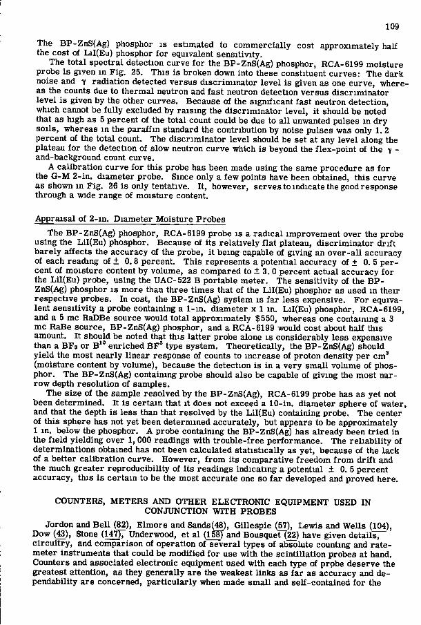
109
The BP-ZnS(Ag) phosphor i s e s t ima ted to c o m m e r c i a l l y cost app rox ima te ly haK the cost of L i I ( E u ) phosphor f o r equivalent s e n s i t i v i t y .
The t o t a l s p e c t r a l de tec t ion cu rve f o r the BP-ZnS(Ag) phosphor, RCA-6199 m o i s t u r e probe i s g iven i n F i g . 25. T h i s i s b r o k e n down into these const i tuent c u r v e s : The d a r k noise and y r a d i a t i o n detected versus d i s c r i m i n a t o r l e v e l i s g iven as one c u r v e , w h e r e as the counts due to t h e r m a l neu t ron and f a s t neu t ron detec t ion v e r s u s d i s c r i m i n a t o r l e v e l i s g iven by the other cu rves . Because of the s i g n i f i c a n t f a s t neu t ron detec t ion , wh ich cannot be f u l l y excluded by r a i s i n g the d i s c r i m i n a t o r l e v e l , i t should be noted that as h igh as 5 percent of the t o t a l count cou ld be due to a l l unwanted pulses i n d r y s o i l s , whereas i n the p a r a f f i n s tandard the c o n t r i b u t i o n by noise pulses was only 1. 2 pe rcen t of the t o t a l count. The d i s c r i m i n a t o r l e v e l should be set at any l e v e l a long the plateau f o r the de tec t ion of s low neut ron cu rve which i s beyond the f l e x - p o i n t of the 7 -and-background count cu rve .
A c a l i b r a t i o n cu rve f o r t h i s probe has been made us ing the same p rocedure as f o r the G - M 2 - i n . d i a m e t e r p robe . Since only a f e w poin ts have been obtained, t h i s c u r v e as shown i n F i g . 26 i s only tenta t ive . I t , however , se rves to indica te the good response th rough a wide range of m o i s t u r e content.
A p p r a i s a l of 2 - i n . D i a m e t e r M o i s t u r e P robes
The BP-ZnS(Ag) phosphor, RCA-6199 probe i s a r a d i c a l i m p r o v e m e n t over the p robe us ing the L i l ( E u ) phosphor. Because of i t s r e l a t i v e l y f l a t plateau, d i s c r i m i n a t o r d r i f t b a r e l y a f f ec t s the accuracy of the probe , i t be ing capable of g iv ing an o v e r - a l l accuracy of each r e a d ing of ± 0 .8 percent . T h i s r ep resen t s a p o t e n t i a l accuracy of ± 0. 5 p e r cent of m o i s t u r e content by vo lume , as compared to ± 3 .0 percent ac tua l accuracy f o r the L i l ( E u ) p robe , us ing the UAC-522 B por t ab le m e t e r . The s e n s i t i v i t y of the B P -ZnS(Ag) phosphor i s m o r e than three t i m e s that of the L i l ( E u ) phosphor as used i n t he i r r e spec t ive probes . In cost , the BP-ZnS(Ag) sys tem i s f a r less expensive. F o r equivalen t s e n s i t i v i t y a probe con ta in ing a 1- in . d i amete r x 1 i n . L i I ( E u ) phosphor, RCA-6199 , and a 5 mc RaDBe source wou ld t o t a l app rox ima te ly $550, whereas one conta in ing a 3 mc RaBe source , B P - Z n S ( A g ) phosphor, and a RCA-6199 would cost about half t h i s amount . I t should be noted that th i s l a t t e r probe alone i s cons iderab ly less expensive than a B F s o r B*° e n r i c h e d B F * type sys t em. T h e o r e t i c a l l y , the BP-ZnS(Ag) should y i e l d the mos t nea r ly l i nea r response of counts to inc rease of p r o t o n densi ty pe r c m ' ( m o i s t u r e content by vo lume) , because the de tec t ion i s i n a v e r y s m a l l vo lume of phosphor . The BP-ZnS(Ag) conta in ing probe should also be capable of g i v i n g the mos t na r r o w depth r e s o l u t i o n of samples .
The s ize of the sample r e s o l v e d by the B P - Z n S ( A g ) , RCA-6199 probe has as ye t not been de t e rmined . I t i s c e r t a i n that i t does not exceed a 1 0 - i n . d i ame te r sphere of wa te r , and that the depth i s less than that r e so lved by the L i l ( E u ) conta in ing p robe . The center of t h i s sphere has not yet been de t e rmined accura te ly , bu t appears to be app rox ima te ly 1 i n . be low the phosphor . A probe con ta in ing the BP-ZnS(Ag) has a l ready been t r i e d i n the f i e l d y i e l d i n g over 1, 000 readings w i t h t r o u b l e - f r e e p e r f o r m a n c e . The r e l i a b i l i t y of de t e rmina t ions obtained has not been ca lcu la ted s t a t i s t i c a l l y as yet , because of the l a c k of a be t te r c a l i b r a t i o n c u r v e . However , f r o m i t s compara t i ve f r e e d o m f r o m d r i f t and the much g rea te r r e p r o d u c i b i l i t y of i t s read ings i nd i ca t ing a po ten t i a l ± 0. 5 pe rcen t accuracy , t h i s i s c e r t a i n to be the mos t accura te one so f a r developed and p r o v e d here .
COUNTERS, M E T E R S A N D O T H E R E L E C T R O N I C E Q U I P M E N T USED I N CONJUNCTION W I T H PROBES
Jordon and B e l l (82), E l m o r e and Sands(48), G i l l e sp i e (57), L e w i s and W e l l s (104), Dow (43), Stone (147)7 Underwood, et a l (ISSJ and Bousquer (22) have g iven de ta i l s , c i r c u i t r y , and c o m p a r i s o n of opera t ion of s e v e r a l types of absolute count ing and r a t e -m e t e r i n s t r u m e n t s that cou ld be m o d i f i e d f o r use w i t h the s c i n t i l l a t i o n probes at hand. Counters and associa ted e l ec t ron ic equipment used w i t h each type of p rpbe deserve the grea tes t a t ten t ion , as they gene ra l ly a re the weakest l i n k s as f a r as accuracy and dependab i l i ty a re concerned, p a r t i c u l a r l y when made s m a l l and se l f - con ta ined f o r the
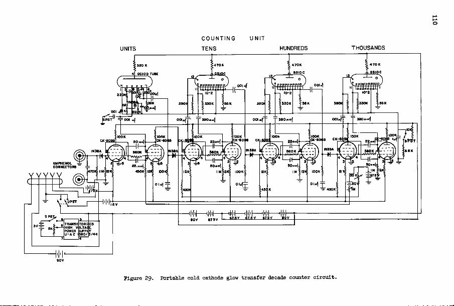
UNITS
C O U N T I N G
T E N S
U N I T
HUNDREDS THOUSANDS
4 7 0 K 4 7 0 K 470K 330 K
6SI0C 6SI0C SSiSS 4 GCIOD TUBE
m i m i
S30K 990 X 330K
^PST -pOOl 41' S 9 0 « u { 0 0 . .fT
IN9SA
ao»o SOiui
W W
430 K
SPST
TRANSIS TORiaED )LTAiE
9B0/E/44 POWER SUPPUV J - A C
Pigure 29. Portable cold cathode glow transfer decade counter c i r c u i t .
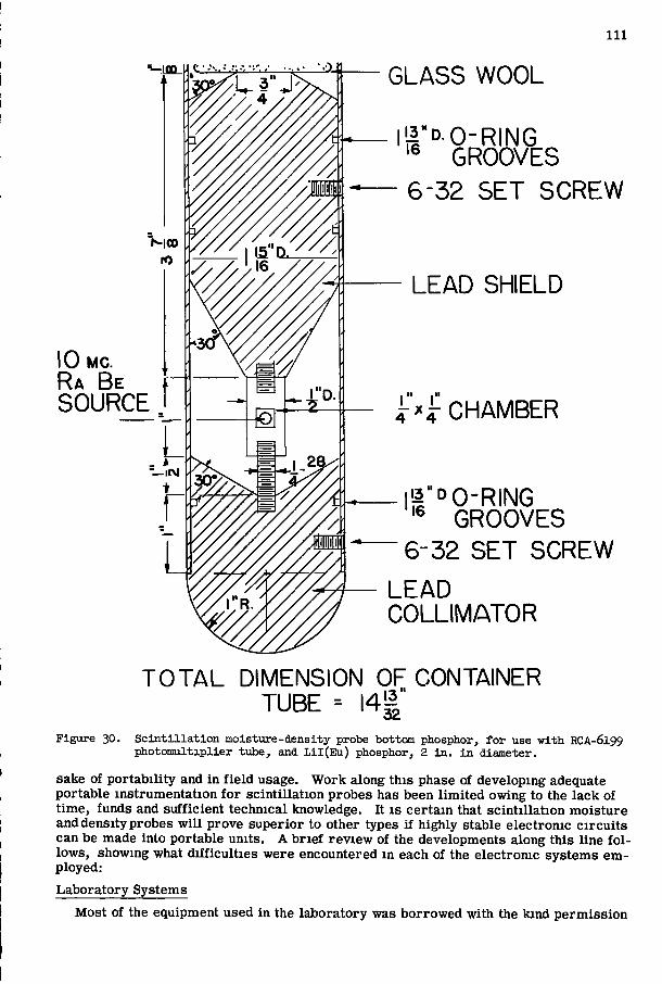
I l l
10 M C .
R a B e SOURCE
G L A S S W O O L
L ' | "D .O-R ING '® GROOVES
6 - 3 2 S E T S C R E W
L E A D SHIELD
I " . . I "
Figure 30.
i r ^ i : C H A M B E R
' I " D O - R I N G '® G R O O V E S
6 - 3 2 S E T S C R E W
L E A D C O L L I M A T O R
T O T A L DIMENSION O F CONTAINER T U B E = I 4 | "
S c i n t i l l a t i o n moisture-density probe bottom phosphor, for use with RCA-6199 photomultiplier tube, and Lil ( E u ) phosphor, 2 in . i n diameter.
sake of p o r t a b i l i t y and i n f i e l d usage. W o r k a long th i s phase of developing adequate por t ab le i n s t r u m e n t a t i o n f o r s c i n t i l l a t i o n probes has been l i m i t e d oiwing to the l a c k of t i m e , funds and s u f f i c i e n t t echn ica l knowledge. I t i s c e r t a i n that s c i n t i l l a t i o n m o i s t u r e and densi ty probes w i l l p rove supe r io r to other types i f h igh ly stable e l ec t ron ic c i r c u i t s can be made in to por tab le un i t s . A b r i e f r e v i e w of the developments a long th i s l i ne f o l l o w s , showing what d i f f i c u l t i e s we re encountered i n each of the e l ec t romc sys tems e m p loyed :
L a b o r a t o r y Systems
M o s t of the equipment used i n the l a b o r a t o r y was b o r r o w e d w i t h the k i n d p e r m i s s i o n
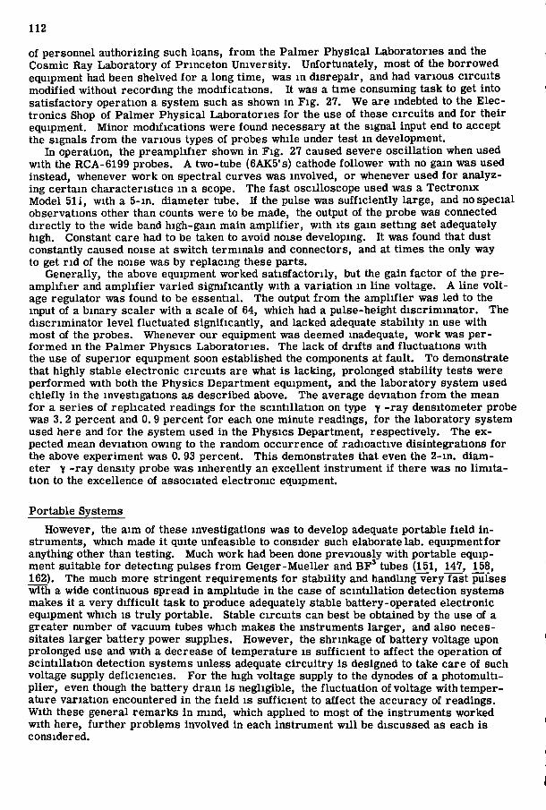
112
of personne l a u t h o r i z i n g such loans, f r o m the P a l m e r P h y s i c a l L a b o r a t o r i e s and the Cosmic Ray L a b o r a t o r y of P r i n c e t o n U n i v e r s i t y . Unfo r tuna te ly , mos t of the b o r r o w e d equipment had been shelved f o r a long t i m e , was m d i s r e p a i r , and had va r i ous c i r c u i t s m o d i f i e d wi thout r e c o r d i n g the m o d i f i c a t i o n s . I t was a t i m e consuming task to get in to s a t i s f a c t o r y opera t ion a sys t em such as shown m F i g . 27. We a re indebted to the E l e c t r o n i c s Shop of P a l m e r P h y s i c a l L a b o r a t o r i e s f o r the use of these c i r c u i t s and f o r t h e i r equipment. M i n o r m o d i f i c a t i o n s were found necessary at the s ignal input end to accept the s ignals f r o m the va r ious types of probes w h i l e under test i n development .
I n opera t ion , the p r e a m p l i f i e r shown i n F i g . 27 caused severe o s c i l l a t i o n when used w i t h the RCA-6199 probes . A two- tube (6AK5's ) cathode f o l l o w e r w i t h no gain was used instead, whenever w o r k on s p e c t r a l cu rves was invo lved , o r whenever used f o r ana lyzi n g c e r t a i n c h a r a c t e r i s t i c s i n a scope. The f a s t osc i l loscope used was a T e c t r o n i x M o d e l 511, w i t h a 5 - i n . d i amete r tube. I f the pulse was s u f f i c i e n t l y l a rge , and no spec ia l observa t ions other than counts w e r e to be made, the output of the p robe was connected d i r e c t l y to the wide band h igh -ga in m a i n a m p l i f i e r , w i t h i t s gain se t t ing set adequately high. Constant ca re had to be taken to avo id noise developing. I t was found that dust constant ly caused noise at s w i t c h t e r m i n a l s and connectors , and at t i m e s the only way to get n d of the noise was by r e p l a c i n g these p a r t s .
Genera l ly , the above equipment w o r k e d s a t i s f a c t o r i l y , but the gain f a c t o r of the p r e a m p l i f i e r and a m p l i f i e r v a r i e d s i g n i f i c a n t l y w i t h a v a r i a t i o n m l ine vol tage . A l ine v o l t age r egu la to r was found to be essent ia l . The output f r o m the a m p l i f i e r was l ed to the input of a b i n a r y sca le r w i t h a scale of 64, wh ich had a pu lse -he igh t d i s c r i m i n a t o r . The d i s c r i m i n a t o r l e v e l f luc tua ted s i g n i f i c a n t l y , and lacked adequate s t a b i l i t y i n use w i t h mos t of the probes . Whenever our equipment was deemed inadequate, w o r k was p e r f o r m e d i n the P a l m e r Phys ic s L a b o r a t o r i e s . The l ack of d r i f t s and f l uc tua t ions w i t h the use of supe r io r equipment soon es tabl i shed the components at f a u l t . T o demonst ra te that h igh ly stable e l ec t ron ic c i r c u i t s are what i s l ack ing , p ro longed s t a b i l i t y tes ts were p e r f o r m e d w i t h both the Phys ic s Depar tmen t equipment, and the l a b o r a t o r y sys t em used c h i e f l y i n the inves t iga t ions as desc r ibed above. The average dev ia t ion f r o m the mean f o r a s e r i e s of r e p l i c a t e d readings f o r the s c i n t i l l a t i o n on type y - r a y dens i tometer probe was 3. 2 percent and 0. 9 percent f o r each one minu te readings , f o r the l a b o r a t o r y sys t em used here and f o r the sys t em used i n the Phys ic s Depar tment , r e spec t i ve ly . The expected mean dev ia t ion owing to the r andom occur rence of r ad ioac t ive d i s in t eg ra t ions f o r the above ejcperiment was 0. 93 percent . T h i s demonst ra tes that even the 2 - i n . d i a m eter "v - r a y densi ty probe was inhe ren t ly an exce l len t i n s t r u m e n t i f t he re was no l i m i t a t i o n to the excel lence of associa ted e lec t ron ic equipment .
Po r t ab l e Systems
However , the a i m of these inves t iga t ions was to develop adequate por tab le f i e l d i n s t rumen t s , wh ich made i t qui te unfeas ib le to cons ider such elaborate lab . equipment f o r anyth ing other than tes t ing . Much w o r k had been done p r e v i o u s l y w i t h por tab le equipment sui table f o r de tec t ing pulses f r o m G e i g e r - M u e l l e r and B F * tubes (151, 147, 158, 162). The much m o r e s t r ingen t r e q u i r e m e n t s f o r s t a b i l i t y and handl ing v e r y f a s t pulses w i t h a wide continuous spread i n ampl i tude i n the case of s c i n t i l l a t i o n de tec t ion sys tems makes i t a v e r y d i f f i c u l t task to produce adequately stable ba t t e ry -ope ra t ed e l ec t ron ic equipment wh ich i s t r u l y po r t ab le . Stable c i r c u i t s can best be obtained by the use of a g rea te r number of vacuum tubes which makes the i n s t rumen t s l a r g e r , and also necess i ta tes l a r g e r ba t t e ry power suppl ies . However , the shr inkage of ba t t e ry voltage upon pro longed use and w i t h a decrease of t empe ra tu r e i s s u f f i c i e n t to a f f e c t the ope ra t ion of s c i n t i l l a t i o n de tec t ion sys tems unless adequate c i r c u i t r y i s designed to take ca re of such voltage supply de f i c i enc ie s . F o r the high vol tage supply to the dynodes of a p h o t o m u l t i p l i e r , even though the ba t t e ry d r a i n i s neg l ig ib le , the f l u c t u a t i o n of vol tage w i t h t e m p e r a ture v a r i a t i o n encountered i n the f i e l d i s s u f f i c i e n t to a f f e c t the accuracy of read ings . W i t h these genera l r e m a r k s i n m i n d , which appl ied to mos t of the i n s t rumen t s w o r k e d w i t h here , f u r t h e r p r o b l e m s invo lved i n each i n s t r u m e n t w i l l be d iscussed as each i s cons idered .
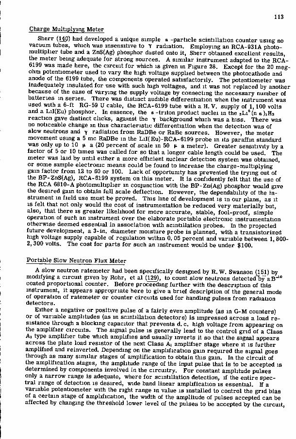
113
Charge M u l t i p l y i n g Me te r
Sher r (140) had developed a unique s i m p l e a - p a r t i c l e s c i n t i l l a t i o n counter us ing no vacuum tubes, wh ich was insens i t ive to "V r a d i a t i o n . E m p l o y i n g an R C A - 9 3 1 A photo-m u l t i p l i e r tube and a ZnS(Ag) phosphor dusted onto i t , Sherr obtained excel lent r e s u l t s , the me te r be ing adequate f o r s t rong sources . A s i m i l a r i n s t r u m e n t adapted to the R C A -6199 was made here , the c i r c u i t f o r which i s g iven i n F i g u r e 28. Except f o r the 20 m e g ohm poten t iometer used to v a r y the h igh vol tage suppl ied between the photocathode and anode of the 6199 tube, the components operated s a t i s f a c t o r i l y . The po ten t iometer was inadequately insu la ted f o r use w i t h such h igh vol tages, and i t was not r ep laced by another because of the ease of v a r y i n g the supply vol tage by connect ing the necessary number of ba t t e r i e s i n s e r i e s . The re was d i s t i nc t audible d i f f e r e n t i a t i o n when the i n s t r u m e n t was used w i t h a 6 - f t RG-59 U cable, the RCA-6199 tube w i t h a H . V . supply of 1,100 vo l t s and a L i I ( E u ) phosphor. I n essence, the a - t n t o n p roduc t nuc le i i n the 3L1® (n a )iH3 r e a c t i o n gave d i s t i nc t c l i c k s , against the 7 background which was a h i s s . The re was no not iceable change i n t h i s c h a r a c t e r i s t i c d i f f e r e n t i a t i o n when the de tec t ion was of s low neutrons and y r a d i a t i o n f r o m RaDBe o r RaBe sources . However , the me te r movement us ing a 5 mc RaDBe i n the L i I ( E u ) - R C A - 6 1 9 9 probe i n i t s p a r a f f i n s tandard was only up to 10 K- a (20 percent of scale i n 50 v- a. m e t e r ) . Grea te r s e n s i t i v i t y by a f a c t o r of 5 or 10 t i m e s was ca l l ed f o r so that a longer cable length cou ld be used. The m e t e r was l a i d by u n t i l e i the r a m o r e e f f i c i e n t nuclear de tec t ion s y s t e m was obtained, o r some s i m p l e e l ec t ron ic means cou ld be found to increase the c h a r g e - m u l t i p l y i n g gain f a c t o r f r o m 12 to 60 or 100. L a c k of oppor tun i ty has prevented the t r y i n g out of the B P - Z n S ( A g ) , RCA-6199 sys t em on th i s me te r . I t i s conf iden t ly f e l t that the use of the RCA 6810-A p h o t o m u l t i p l i e r i n con junc t ion w i t h the B P - Z n ( A g ) phosphor would give the d e s i r e d ga in to obtain f u l l scale d e f l e c t i o n . However , the dependabi l i ty of the i n s t r umen t i n f i e l d use mus t be p r o v e d . T h i s l i n e of development i s i n our p lans , as i t I S f e l t that not on ly would the cost of i n s t r u m e n t a t i o n be reduced v e r y m a t e r i a l l y but, a lso , tha t t he re i s g rea te r l i k e l i h o o d f o r m o r e accurate , s table , f o o l - p r o o f , s i m p l e opera t ion of such an i n s t r u m e n t over the e laborate po r t ab le e l ec t ron ic i n s t r u m e n t a t i o n o the rwise deemed essent ia l i n assoc ia t ion w i t h s c i n t i l l a t i o n probes . In the p r o j e c t e d f u t u r e development , a 3 - i n . d i amete r m o i s t u r e probe i s planned, w i t h a t r a n s i s t o r i z e d high vol tage supply capable of r egu l a t i on w i t h i n 0. 05 percent and v a r i a b l e between 1,800-2 ,300 v o l t s . The cos t f o r p a r t s f o r such an i n s t r u m e n t w o u l d be under $100.
P o r t a b l e Slow Neu t ron F l u x M e t e r
A s low neut ron r a t e m e t e r had been s p e c i f i c a l l y designed by R. W. Swanson (151) by m o d i f y i n g a c i r c u i t g iven by Rohr , et a l (129), to count s low neutrons detected by a B " ' ° coated p r o p o r t i o n a l counter . B e f o r e p roceed ing f u r t h e r w i t h the d e s c r i p t i o n of t h i s i n s t rumen t , i t appears appropr ia t e here to give a b r i e f d e s c r i p t i o n of the genera l mode of ope ra t ion of r a t e m e t e r o r counter c i r c u i t s used f o r handl ing pulses f r o m r a d i a t i o n de tec tors .
E i t h e r a negative o r pos i t i ve pulse of a f a i r l y even ampl i tude (as m G - M counters) o r of va r i ab l e ampl i tudes (as i n s c i n t i l l a t i o n detectors) i s i m p r e s s e d across a load r e s is tance through a b l o c k i n g capaci tor that p revents d. c. high vol tage f r o m appear ing on the a m p l i f i e r c i r c u i t s . The s i g n a l pulse i s genera l ly lead to the c o n t r o l g r i d of a Class A l type a m p l i f i e r tube which a m p l i f i e s and usua l ly i n v e r t s i t so that the s igna l appears ac ross the pla te load r e s i s t o r of the next Class A i a m p l i f i e r stage where i t i s f u r t h e r a m p l i f i e d and r e i n v e r t e d . Depending on the a m p l i f i c a t i o n gain r e q u i r e d the s i g n a l goes th rough as many s i m i l a r stages of a m p l i f i c a t i o n to obta in th i s gain. I n the c i r c u i t of the a m p l i f i c a t i o n stages, the ampl i tude range of the input pulse that i s to be accepted i s de t e rmined by components i nvo lved i n the c i r c u i t r y . F o r constant ampl i tude pulses only a n a r r o w range i s adequate, where f o r s c i n t i l l a t i o n detect ion, i f the e n t i r e spect r a l range of de tec t ion i s des i red , w ide band l i n e a r a m p l i f i c a t i o n i s essent ia l . I f a v a r i a b l e po ten t iometer w i t h the r i g h t range i n value i s i n s t a l l e d to c o n t r o l the g r i d b ias of a c e r t a i n stage of a m p l i f i c a t i o n , the w i d t h of the ampl i tude of pulses accepted can be a f f ec t ed by changing the th re sho ld lower l e v e l of the pulses to be accepted by the c i r c u i t ,
114
and i n e f f e c t t h i s becomes a s i m p l e pulse height d i s c r i m i n a t o r . I n a r a t em e te r , the pulses c o m i n g f r o m the las t a m p l i f i c a t i o n stage a re shaped so
that i r r e s p e c t i v e of the ampl i tude of the input pulse to the f i r s t a m p l i f i e r stage, a p r o p e r ampl i tude pulse i s put out so as to " t r i g g e r " a m u l t i v i b r a t o r c i r c u i t . A r e s i s t o r -capac i to r coup l ing causes the m u l t i v i b r a t o r to o s c i l l a t e at a spec i f i c r a t e which de te r mines the t i m e base of the m u l t i v i b r a t o r c i r c u i t . D u r i n g one such p e r i o d , the m u l t i v i b r a t o r r e m a i n s i n i t s unstable state thus averag ing the charge accumula ted w i t h i n th i s p e r i o d . I f t h i s charge i s p e r m i t t e d to f l o w th rough a me te r , the input pulse r a t e r e m a i n i n g constant, the longer the t i m e base, the g rea t e r w i U be the average c u r r e n t f l o w i n g th rough the m e t e r . Hence, f o r va r i ous scale ranges , a f i x e d res i s tance can be coupled by sw i t ch ing w i t h a s e r i e s of capac i to r s i n steps of v a r y i n g values (or v i ce ve r sa ) , so that a steady s igna l input r a t e wou ld y i e l d v a r y i n g me te r needle def lec t ions f o r each of the ranges . M e t e r s a lso cou ld be made to have s e v e r a l " t i m e cons tan t s . " The t i m e constant of a me te r i s the p e r i o d of t i m e w h i c h i t takes f o r the mete r needle to de f l ec t f r o m 0 to half scale of the value of the c u r r e n t f l o w i n g th rough the me te r . T h i s f e a t u r e of r a t e m e t e r s i s v e r y u s e f u l as i t makes poss ib le the dampening of f l u c tuat ions of s t a t i s t i c a l v a r i a t i o n inherent i n the r a t e of r a d i a t i o n detected, so that m o r e accurate readings cou ld be obtained d i r e c t l y f r o m the me te r , as t i m e p e r m i t s .
The r a t e m e t e r made here , f o l l o w e d Swanson's basic c i r c u i t . I t employed three stages of a m p l i f i c a t i o n us ing 1L4 tubes. I t was m o d i f i e d to accept both pos i t i ve and negative pulses by sw i t ch ing i n a phase t r a n s f o r m e r when the input pulses were pos i t i ve . The non-ove r load f e a t u r e of the Swanson c i r c u i t was m o d i f i e d i n an a t tempt to take m as wide a band of pulses as poss ib le . The d i s c r i m i n a t o r b ias p laced on the c o n t r o l g r i d of the second a m p l i f i e r tube was m o d i f i e d to give a complete range of d i s c r i m i n a t i o n by us ing a p r e c i s i o n v e r n i e r po ten t iometer so that y - r a d i a t i o n and background could be obtained i f wanted, and a lso a l l pulses be low any d e s i r e d l e v e l b locked out i f necessary . The d i s c r i m i n a t e d pulse was a m p l i f i e d f u r t h e r i n the t h i r d a m p l i f i c a t i o n stage wh ich i s then f e d to the m u l t i v i b r a t o r c i r c u i t wh ich in tegra tes the pulse on a t i m e base se lected by sw i t ch ing m a sui table value res i s tance (potent iometer ) coupled w i t h a capac i tor on the range se lec t ion s w i t c h . T h e r e a r e f o u r such p a i r s of " R C " coupl ings to g ive f o u r scale ranges , po ten t iomete r s be ing used so that the t i m e base could be s l i g h t l y a l t e r e d to give c o r r e c t me t e r d e f l e c t i o n f r o m range to range. The s ingle t i m e constant e m ployed i n the me te r i s 12. 5 sees.
I t was found that c a r e f u l component l ay -ou t plans were necessary to i n s t a l l p a r t s i n c lose p r o x i m i t y to o thers i nvo lved m a c i r c u i t , to prevent a high noise l e v e l . Each tube i s e l e c t r o s t a t i c a l l y shie lded. F u r t h e r , the f i r s t two stages of a m p l i f i c a t i o n should have been shie lded e f f e c t i v e l y f r o m the r e s t of the c i r c u i t r y , and Underwood, et a l (158) r ecommended the a m p l i f i e r - d i s c r i m i n a t o r un i t to be shie lded by housing th i s stage i n an inner chass is . Such care i n sh ie ld ing was not main ta ined i n cons t ruc t i ng the i n s t r u ment used here , though i t i s f e l t that such ca re was w a r r a n t e d .
T h i s me t e r w o r k e d adequately f o r handl ing the pulses f r o m both the m o i s t u r e and densi ty probes e m p l o y i n g the RCA-6199 d i r e c t l y . Of a l l the m e t e r s used here , t h i s had the grea tes t s t a b i l i t y g i v i n g i d e n t i c a l readings every t i m e f o r the same r a t e of r a d i a t i o n . C e r t a i n d i f f i c u l t i e s w e r e encountered wh ich s t i l l r e m a i n unsolved owing c h i e f l y to a l ack of t i m e to w o r k out the p r o b l e m s . F i r s t , i t appears that the t a m p e r i n g w i t h the non-eve r load c i r c u i t r y d i d not y i e l d the d e s i r e d r e s u l t s , and was p robab ly the cause of o s c i l l a t i o n at h igh count ing r a t e s because o f p i l e - u p o f pulses . The chief d i f f i c u l t y was that w i t h the s c i n t i l l a t i o n probes , the .mete r ranges sca rce ly operated. I t was at f i r s t deduced that the long t i m e bases used were to b lame; t h e r e f o r e , s m a l l e r values of r e s i s t o r -capac i tor coupl ings i n the range s w i t c h w e r e t r i e d out. Though the p e r f o r m a n c e i m p r o v e d somewhat , the ranges s t i l l d i d not spread enough to the r e q u i r e d extent . I t appeared that the c i r c u i t r y was inadequate to handle the pulses f r o m s c i n t i l l a t i o n sys tems . L a c k i n g the t echnica l knowledge and t i m e to c o r r e c t f o r these de f i c i enc ie s , and the exigencies of other compet ing inves t iga t ions to be p e r f o r m e d , f o r c e d a t e m p o r a r y she lv ing of th i s m e t e r . However , because of the excel lent s t a b i l i t y and o v e r - a l l s i m p l i c i t y of t h i s me te r , i t i s planned to w o r k out the d i f f i c u l t i e s of the c i r c u i t s so as to s a t i s f a c t o r i l y measure the output f r o m s c i n t i l l a t i o n probes .
115
Cold Cathode G l o w - T r a n s f e r Type Counter
Stone, et a l (147) had developed an absolute count ing por t ab le , ba t t e ry opera ted me te r employ ing f o u r GSIOC co ld cathode g low t r a n s f e r tubes. The authors a re g r ea t l y indebted to M r . Stone f o r the generous help he has g iven i n m a k i n g avai lable his c i r c u i t s and m o d i f i c a t i o n s thereof . The f i r s t i n s t r u m e n t that was made acco rd ing to the c i r c u i t employ ing f o u r GSIOC tubes w o r k e d w e l l , handl ing pulses f r o m e i the r the 2 - i n . d i amete r densi ty or m o i s t u r e probe d i r e c t l y wi thou t any a m p l i f i c a t i o n . The pulses a re f e d to the u n i v i b r a t o r c i r c u i t of the f i r s t (units) stage, w h i c h cons is t s of the f i r s t two s u b - m i n i a t u r e CK-6088 tubes. Each pulse f e d to the u n i v i b r a t o r , t r i g g e r s the e lec t ron ic decade counter which i s v i s i b l y indica ted by the t r a n s f e r of a " g l o w " to the next p m . Upon c o m p l e t i n g 10 counts, a pulse i s t r a n s f e r r e d to the u n i v i b r a t o r c i r c u i t of the " tens" stage, and so on, f o r the "hundreds" and "thousands" stages. I n e f f ec t , th i s becomes an e lec t ron ic absolute counter wh ich rep laces a mechan ica l counter that r e q u i r e s cons iderab ly m o r e power f o r i t s ope ra t ion and, of course , i s not capable of r e g i s t e r i n g such high counting ra tes . The l i m i t a t i o n of the GSIOC tube was i t s long dead t i m e of 300 microseconds , i t be ing capable of handl ing count ing ra tes f r o m 0 - 4, 000 cps. The densi ty probe us ing the N a I ( T l ) - R C A - 6 1 9 9 sys tem gave a higher count than th i s at l ow d i s c r i m i n a t o r se t t ings . Owing to the grea t po ten t i a l value of a good po r t ab l e , ba t t e ry operated i n s t rumen t , i t was decided to m o d i f y th i s i n s t r u m e n t by r e p l a c i n g the bu lky ba t t e r i e s w i t h a t r a n s i s t o r i z e d h igh vol tage power supply, and to include a m o d i f i e d c i r c u i t that Stone had k ind ly made avai lable th rough pe r sona l correspondence, wh ich subst i tu ted a GCIOD tube f o r the " u n i t s " stage GSIOC tube. T h i s "deka t ron" tube has a dead t i m e of only 50 mic roseconds and i s capable of counti n g up to 20, 000 cps.
The m o d i f i e d c i r c u i t employed i s g iven i n F i g . 29. The t r a n s i s t o r i z e d h igh vol tage power supply operated s a t i s f a c t o r i l y , being h igh ly s table . However , the count ing me te r ceased to operate p r o p e r l y . A t f i r s t , excessive o s c i l l a t i o n appeared across the s igna l input . B y r e a s s e m b l i n g p a r t s and employ ing sh ie ld ing , the o s c i l l a t i o n was reduced so that i t could be d i s c r i m i n a t e d against . However , th i s height of d i s c r i m i n a t i o n a lso cut out mos t of the Y counts f r o m the N a I ( T l ) - R C A - 6 1 9 9 probe . I t appeared that the GCIOD tube c i r c u i t r y was at f a u l t , or else the tube i t s e l f was not s table . A f t e r a f e w a t tempts at r e c t i f y i n g the d i f f i c u l t y , the me te r had to be t e m p o r a r i l y shelved i n f a v o r of e x e r t i n g m o r e e f f o r t on the development and t e s t i ng of the probes . T w o f ea tu re s of such absolute count ing me te r s a re po ten t i a l ly poor . The f i r s t i s that readings mus t be taken i n the f i e l d w i t h a s topwatch. F o r a t w o - m i n u t e r ead ing even a one second e r r o r i n t i m i n g w o u l d give a 0. 9 pe rcen t e r r o r i n counts. The other i s , s ince c a l i b r a t i o n of the p robe has to be done constant ly against a s tandard, great d i f f i c u l t y would be encountered i f the s tandard was to be brought to a spec i f i c count r a t e each t i m e by adj u s t i n g the d i s c r i m i n a t o r c o n t r o l . I t i s des i rab le f r o m the standpoint of g rea te r a c c u r acy to use a f i x e d count, r a the r than hav ing a v a r i a b l e count f o r the s tandard, as w i l l be poin ted out l a t e r . However , i f t i m e i s not the greates t p r i o r i t y , such a po r t ab le absolute count ing me te r i s po ten t i a l ly capable of grea ter accuracy than a r a t e m e t e r hav ing the same s t a b i l i t y of the d i s c r i m i n a t o r c i r c u i t contained i n the absolute count m e t e r . F o r a thorough c o m p a r i s o n of count ing r a t e m e t e r s and sca l e r s the reader i s r e f e r r e d to Bousquet (22).
T r a n s i s t o r i z e d M o d e l UAC-522 B P r e c i s i o n Ratemeter
The recen t development of a v e r y l i gh t , por tab le p r e c i s i o n i a temeter f o r use w i t h s c i n t i l l a t i o n probes announced by the U n i v e r s a l A t o m i c s D i v i s i o n of the U n i v e r s a l T r a n s i s t o r P roduc t s C o r p o r a t i o n appeared to be the answer to our need by the way of a p r e c i s i o n , po r t ab l e , ba t t e ry -ope ra ted , s table f i e l d i n s t r u m e n t . W i t h the gene ra l f a i l u r e of our l a b o r a t o r y por t ab le me te r s to operate as des i red , th i s newly developed c o m m e r c i a l me t e r was invested i n as a d i r e necessi ty . T h i s me te r has been the only one m sys temat ic use throughout f i e l d t r i a l s f o r a l l probes developed here up to date.
T h i s me t e r cons i s t s of a 1 4 - t r a n s i s t o r c i r c u i t . T h e r e a r e s e v e r a l a m p l i f i e r stages so that as l ow an input as 0. 015 vo l t s w i l l give a me te r response. The i n s t r u m e n t also
116
has the f o l l o w i n g f ea tu res which make i t h igh ly commendable :
(1) Six range scales c o v e r i n g 0 - 10, 000 cps. (2) A n i n t e r n a l pulse generator w o r k i n g at 1, 500 cps f o r on- the-spot c a l i b r a t i o n . (3) I t has e i ther 110 vo l t s 60 cps AC l i n e opera t ion , o r ba t t e ry opera t ion . Power
f o r ba t t e ry opera t ion i s suppl ied by s i x l / 2 - v o l t n i c k e l - c a d m i u m ce l l s that a re capable of opera t ing the i n s t r u m e n t f o r 50 hours wi thou t r e c h a r g i n g . These ce l l s a re r echa rge able 200 t i m e s , and hence a re capable of opera t ing f o r 10, 000 hours . A l s o , a 22y2 -vol t ba t t e ry , and a m e r c u r y p r i m a r y c e l l are used.
(4) I t has f o u r t i m e cons tan t s—1 sec, 5 sec, 20 sec and 120 s e c — w h i c h p e r m i t both r a p i d mete r response to count ing ra te and v e r y steady needle response f o r grea ter accuracy of readings ,
(5) I t weighs only 10^2 l b .
The f ea tu res that w e r e found somewhat l a c k i n g w e r e :
(1) The accuracy was + 2 percen t of f u l l scale on a l l ranges but th i s dropped o f f cons iderab ly , be ing ± 4 percen t at about 60 percen t of f u l l range a round wh ich mos t readings were obtained, A l a r g e r d i a l me te r should ove rcome th is defec t cons iderab ly .
(2) The t r a n s i s t o r i z e d regu la ted high vol tage power supply capable of continuous v a r i a t i o n f r o m 700 vo l t s to 1, 300 vo l t s , al though of compact s ize and nove l c i r c u i t r y , l acked somewhat i n s t a b i l i t y . In the f i e l d , not only was i t found that the h igh vol tage dropped s teadi ly , though only s l i g h t l y , on constant ope ra t ion but, a lso, there w e r e at t i m e s s m a l l f l uc tua t i ons . The r e p o r t e d d r i f t of ± 0 , 1 percent m any 8-hour p e r i o d d u r i n g opera t ion on ba t t e r i e s was e i ther exceeded, o r was s u f f i c i e n t to m a t e r i a l l y a f f e c t the accuracy of the i n s t r u m e n t .
(3) The d i s c r i m i n a t o r c i r c u i t was found to be too unstable f o r the purposes employed here . I n spi te of a p r e c i s i o n v e r n i e r po ten t iometer i n s t a l l e d l a t e r , the v a r i a b i l i t y of the d i s c r i m i n a t o r l e v e l on the f i e l d was found to be the chief cause of inaccura te r e a d ings . T h i s was p a r t i c u l a r l y t r u e when t empera tu re v a r i a t i o n d u r i n g the day was c o n s iderable , and when the a i r t empera tu re rose above 85 deg F . Perhaps the r ep l ace ment of g e r m a n i u m t r a n s i s t o r s by s i l i c o n t r a n s i s t o r s on th i s c i r c u i t w o u l d adequately take c a r e of the p r o b l e m .
The me te r operated s a t i s f a c t o r i l y i n genera l , except f o r the f o r e g o i n g defects . A t t i m e s , however , f o r no apparent reason, the me te r wou ld f luc tua te excess ive ly . A l s o , on occasion, the sw i t ch ing f r o m one scale to another wou ld render as h igh as 20 p e r cent e r r o r i n r ead ing a constant count ing ra te on one scale as compared to the o ther . A n i m p r o v e d i n s t r u m e n t of t h i s type, which s a t i s f a c t o r i l y ove rcomes the above m e n t ioned d i f f i c u l t i e s , appears to be j u s t the i n s t r u m e n t r e q u i r e d f o r use i n con junc t ion w i t h s c i n t i l l a t i o n m o i s t u r e and densi ty probes i n the f i e l d .
Scope of Fu tu re Development of I n s t rumen ta t i on
F r o m the f o r e g o i n g , i t i s c l ea r that the e l e c t r o m c - t r a n s i s t o r i n d u s t r y i s qui te capable of developing i n s t rumen t s c o m m e r c i a l l y wh ich cou ld s a t i s f y the s t r ingen t r e qu i r emen t s f o r use of s c i n t i l l a t i o n probes m con junc t ion w i t h h igh ly stable po r t ab l e , p r e c i s i o n r a t e m e t e r s . I t i s m e r e l y a ma t t e r of demand to j u s t i f y the e:q)ense of f u r ther development . The cost of an adequately stable t r a n s i s t o r i z e d p r e c i s i o n r a t e m e t e r such as an i m p r o v e d U A C 522 B i n the respec ts ind ica ted should not be over $850. I f such a me te r were developed and i f i t we re capable of g i v i n g cons is ten t ly dependable, accurate r e s u l t s , i t s v e r s a t i l i t y wou ld render i t the mos t des i rab le me te r f o r use w i t h e i t he r s c i n t i l l a t i o n , B F 3 o r G e i g e r - M u e l l e r coun te r s .
However , there i s a great deal to be sa id i n f a v o r of s imp le i n s t r u m e n t s wh ich can operate wi thout the use of t r a n s i s t o r s and e l ec t ron ic tubes. W i t h the recen t development of the RCA-6810 p h o t o m u l t i p l i e r (see Tab le 3) , i t i s poss ib le to obta in such a h igh gain of l i n e a r a m p l i f i c a t i o n by the tube i t s e l f (12. 5 x lO ' ) that i t obviates the necess i t y of complex wide band f a s t pulse l i n e a r a m p l i f i e r c i r c u i t s . I t appears f ea s ib l e to e l i m i n a t e e l e c t r o n tube c i r c u i t s a l together , i f such a c i r c u i t as shown i n F i g . 28 cou ld be m o d i f i e d to f u n c t i o n s a t i s f a c t o r i l y w i t h the RCA-6810 . Not only wou ld th i s reduce the cost of i n s t r u m e n t a t i o n v e r y m a t e r i a l l y , but i t should be capable of r e n d e r i n g m o r e de-
117
pendable, accurate and s table r e s u l t s . Research along these l ines i s at p resen t under way. The grea te r s e n s i t i v i t y of the 6,810 tube should enable the use of s m a l l e r i n t e n s i t y sources , f u r t h e r r educ ing the cost of i n s t rumen ta t i on , and po ten t i a l r a d i a t i o n hazard .
The mos t apparent need f o r i nc r ea s ing the v e r s a t i l i t y of these probes so that they a re capable of p r o b i n g to any des i r ed depth i s f o r a p r e a m p l i f i e r to be cons t ruc ted w i t h i n the probe i t s e l f . T h i s would also add to the accuracy and dependabi l i ty of r e s u l t s obtained. T h e probes u s ing the 6199 opera te s a t i s f a c t o r i l y to p robe depths up to 10 f t u s ing 1 2 - f t RG-59 U cable lengths . Upon f u r t h e r increase i n length the pulses a re attenuated so that i nc r ea s ing ly f e w e r counts cause a r e g i s t r y on the r a t e m e t e r . B y r a i s i n g the h igh vol tage supply to the l i m i t f o r the p h o t o m u l t i p l i e r tube and r educ ing the d i s c r i m i n a t o r l e v e l to b lock out only unwanted pulses , i t i s poss ib le to use up to 20 f t . of cable length w i t h the probes developed here , emp loy ing the s imp le c i r c u i t w i t h the 6199 p h o t o m u l t i p l i e r tubes. However , the accuracy of the sys t em becomes poo re r , and the sys t em becomes cons iderably m o r e t emperamen ta l .
What IS r e q u i r e d i s a p r e a m p l i f i e r - c a t h o d e f o l l o w e r f o r each probe . W i t h the use of e l ec t ron tubes, i t would become necessary to t h e r m a l l y i so la te the p r e a m p l i f i e r f r o m the r e s t of the p robe as heat f l o w by conduct ion i s o the rwise l i k e l y to a f f ec t the t h e r m i onic e m i s s i o n ra t e of the p h o t o m u l t i p l i e r tube. I t i s poss ible to f i t a ba t t e ry supply i n a 2 - i n . d iamete r or l a r g e r probe , but not i n a 1 m . d iamete r one, so as to s i m p l i f y w i r i n g , i f e l ec t ron ic tubes a re used. A two- tube c i r c u i t should be adequate, but even f o r two s u b - m i n i a t u r e tubes, the ba t t e ry d r a i n f o r heater and pla te supplies wou ld be as much as 5 wat t s .
T r a n s i s t o r s o f f e r the bes t means f o r use i n p r e a m p l i f i e r - c a t h o d e f o l l o w e r c i r c u i t s f o r s c i n t i l l a t i o n probes as s m a l l as 1 i n . i n d i ame te r . The best a r rangement wou ld be to house a l l the c i r c u i t components and ba t t e ry supplies a long w i t h the vol tage d i v i d e r i n a longer length of tube, i n " b u l l e t - t y p e " cons t ruc t ion . F o r a 2 - o r 3 - i n . d i amete r probe i t may be poss ib le to use a t r a n s i s t o r i z e d high vol tage supply w i t h m the probe i t self , operated f r o m a s ingle D- type c e l l , and so f u r t h e r s i m p l i f y the w i r i n g . I f the s c i n t i l l a t i o n sys t em probes are to operate m o r e s a t i s f a c t o r i l y , and at g rea te r depths, the development of sui table p r e a m p l i f i e r - c a t h o d e f o l l o w e r c i r c u i t s i s a p r i m e necess i t y , and hence deserves p r i o r i t y i n a t tent ion.
Fu tu re Development of Probes
The d i r e c t i o n of f u t u r e r e s e a r c h i s towards the m a k i n g of the f o l l o w i n g i n s t r u m e n t s :
(a) M o i s t u r e densi ty s c i n t i l l a t i o n probes equipped w i t h p r e a m p l i f i e r - c a t h o d e f o l l o w e r s that a r e 1 i n . i n d i ame te r . The m o i s t u r e probe w i l l employ the B o r o n P l a s t i c -ZnS(Ag) type c r y s t a l .
(b) A m o i s t u r e - d e n s i t y p robe us ing a 10 mc RaBe source , RCA-6199 and a L i l ( E u ) c r y s t a l w i t h a source to c r y s t a l distance of app rox ima te ly 14 c m . I n theory , the re i s l i t t l e reason why such a probe should not f u n c t i o n adequately to give accura te m o i s t u r e and densi ty de te rmina t ions . Such a probe has a l ready been cons t ruc ted here as i n F i g . 30. A h igh ly stable e l ec t ron ic sys tem must , however, be used m con junc t ion w i t h such a probe i f accurate readings a re to be obtained. No p r a c t i c a l w o r k has so f a r been done i n t e s t i ng the f e a s i b i l i t y of t h i s p robe .
(c) A n at tenuat ing geomet ry dens i tometer us ing C o " as a source and one of the photo-m u l t i p l i e r s w i t h i t s end f a c i n g the source , to make l a b o r a t o r y de te rmina t ions of wet densi ty of co re samples , b locks , cubes and f o r spec ia l s tudies where s t r i c t l o c a l i z a t i o n of the vo lume measured i s i m p e r a t i v e .
(d) A f a s t neu t ron a t tenuat ing h y g r o m e t e r u t i l i z i n g i n end- to-end geomet ry a f a s t neu t ron source and a sui table p h o t o m u l t i p l i e r ac ross a spec i f i c " c e l l - d e p t h " i n wh ich the sample of u n i f o r m d imens ions i s p laced. The phosphor to be used f o r such a probe should be such as Hornyak (77) and H a r d i n g (63) have employed us ing ZnS(Ag), o r a p l a s t i c s c i n t i l l a t o r such as H a r r i s (64) has desc r ibed f o r f a s t neut ron detec t ion .
P robes such as desc r ibed i n (c) and (d) should p r ed i c t ab ly become r e g u l a r l a b o r a t o r y equipment f o r rou t ine so i l s and m a t e r i a l s t e s t ing i n a f e w y e a r s . The r e s e a r c h s c i e n t i s t s , such nuclear p robes wou ld make poss ib le non-des t ruc t ive measurements of water movements under va r i ous types of po ten t ia l s , and the continuous measurement of densi ty
118
by non-des t ruc t ive means, to enable c e r t a i n types of inves t iga t ions wh ich had h i t h e r t o been beyond the r e a l m of p o s s i b i l i t y .
P rocedure f o r Obta in ing I n Situ Measurements of Soi l Dens i ty and M o i s t u r e Content
I t mus t be recogn ized that notwi ths tanding the po ten t i a l accuracy of i n s t rumen t s used m any measurement , the manner i n wh ich such measurements a re p e r f o r m e d eventual ly de te rmines the ac tua l accuracy obtained w i t h the method employed. The impor t ance of us ing the best p rocedures to obta in accurate r e s u l t s w i t h the s c i n t i l l a t i o n and other probes cannot be overemphas ized .
D u r i n g extensive job use of the i n s t r u m e n t s , m a i n l y underneath c i t y s t ree t s , much was l e a rned w i t h r espec t to the type of d r i l l i n g opera t ions necessary to p r e p a r e the hole to r ece ive the access tube in to which the probes were i n s e r t e d w h i l e t ak ing read ings . C e r t a i n recommendat ions a re t h e r e f o r e s p e c i f i e d i n Appendix 1 that should be adhered to i f s i g n i f i c a n t inaccurac ies a r i s i n g f r o m i m p r o p e r l y made holds a re to be avoided. Speci f ica t ions are g iven f o r the m a k i n g of holes to accept the 2 ? i 6 - i n . outside d iamete r access tube used f o r the r ecep t ion of 2 - i n . d i amete r p robes .
Besides m a k i n g holes c o r r e c t l y i n the f i e l d , i t i s i m p e r a t i v e that readings be taken c a r e f u l l y and i n a c e r t a i n manner dependent c h i e f l y on the nature of the m e t e r s being used. Standards that double as shie lds should a lways be set of f the ground on a s too l d u r i n g c a l i b r a t i o n . I t mus t be r e m e m b e r e d that no e l e c t r o m c p r e c i s i o n equipment can be expected to r e m a i n stable u n t i l i t has been " w a r m e d up" f o r over an hour be fo re any readings a re taken. Po r t ab l e , b a t t e r y - p o w e r e d equipment needs constant ba t t e ry checki n g and r e p l a c i n g i f not up to pa r . Because of expected d r i f t , c a l i b r a t i o n against the s tandard mus t be r e s o r t e d to p r e f e r a b l y at constant i n t e r v a l s of t i m e , and read ings mus t be taken i n a spec i f i c manner to enable easy ca l cu l a t i on i n o rde r to e l i m i n a t e the e r r o r i n counts due to d r i f t and to obta in the greates t s t a t i s t i c a l accuracy of each r ead ing i n the t i m e ava i lab le . Hence, a s tep-by-s tep p rocedure i s ou t l ined i n Appendix 2, to act as a guide i n obta in ing accura te readings i n the shor tes t poss ib le t i m e , w i t h the m e t e r s and probes at hand.
The manner of c a l cu l a t i ng r e s u l t s p a r t i c u l a r l y m sys tems which tend to d r i f t c o n s ide rab ly d u r i n g use, i s v e r y i m p o r t a n t i f e r r o r in t roduced due to d r i f t i s to be kept at a m i n i m u m . Unless a sys t em i s v e r y stable so that a constant value can be obtained m counts f o r each s tandard of each method of measurement , i t i s not r ecommended that c a l i b r a t i o n curves us ing counts ve r sus densi ty or m o i s t u r e content be d rawn . I t i s essen t i a l that the r a t i o of counts f o r the measurement to counts f o r the s tandard be obta ined f o r each type of d e t e r m i n a t i o n ( m o i s t u r e o r densi ty) and that t h i s r a t i o i s p lo t t ed against m o i s t u r e content o r wet dens i ty . F u r t h e r , i f the s igna l to noise r a t i o changes cons iderab ly m the range of d r i f t encountered, i t i s i m p o r t a n t that another manner of ca l cu l a t i ng the sample to s tandard r a t i o of counts becomes necessary. T o c l a r i f y the s ign i f i cance of c o r r e c t p rocedures i n ca l cu l a t i ng ac tual d r y densi ty and m o i s t u r e contents f r o m the read ings obtained us ing the nuclear probes on the f i e l d , an ac tua l datasheet f r o m the rou t ine data obtained on the job , and v a r i o u s methods of ca l cu l a t i on w i t h t he i r expected accurac ies , a r e g iven i n Appendix 3.
S U M M A R Y A N D CONCLUSIONS
The development of nuclear techniques f o r s o i l d ens i t ome t ry and h y g r o m e t r y has been t r a ced h i s t o r i c a l l y and the s c i e n t i f i c p r i n c i p l e s u n d e r l y i n g these techniques have been presented . The po ten t i a l advantages of s c i n t i l l a t i o n de tec t ion have been poin ted out and the p r i n c i p l e s on wh ich such detec t ion i s based have been discussed i n d e t a i l together w i t h the func t i on ing and c h a r a c t e r i s t i c s of the components of s c i n t i l l a t i o n det ec t ion sys tems .
The ac tual cons t ruc t i on and p e r f o r m a n c e of nuclear m o i s t u r e and dens i ty p robes developed i n th i s w o r k have been r e p o r t e d . The evaluat ion of each probe sys t em i s s u m m a r i z e d be low:
(1) 1- in. d i ame te r . Na t iona l Radiac probes us ing a D u M o n t K-1303 tube w i t h i n t e r changeable c r y s t a l s {% i n . d i ame te r x 1 i n . N a l ( T l ) , and fa i n . x 1 i n . L i l ( E u ) ) . The

119
output f r o i n the p r e a m p l i f i e r had to be h igh ly a m p l i f i e d (x 1000) i n o r d e r to operate a 1-vol t input l a b o r a t o r y sca le r . The two- tube p r e a m p l i f i e r located i n the s c i n t i l l a t i o n p robe caused excessive t h e r m i o m c e m i s s i o n f r o m the K-1303 p h o t o m u l t i p l i e r because of the heat d iss ipa ted at the pla tes and heaters of the e l e c t r o n tubes and conducted to the p h o t o m u l t i p l i e r . The supply vol tages not only to the p h o t o m u l t i p l i e r but a lso to the p r e a m p l i f i e r had to be h ighly regula ted i n o r d e r to obta in any reasonable readings . The heat ing-up p r o b l e m , the need f o r a high degree of r e g u l a t i o n of vol tage suppl ies and the need f o r a h igh f a c t o r of a m p l i f i c a t i o n w e r e some of the i m p o r t a n t reasons f o r r e j e c t i n g the probes us ing the K-1303 tube f r o m f u r t h e r tes t ing .
(2) 1-in, d i amete r probes u t i l i z i n g the ten-stage ?4 i n . d i amete r K-1382 p h o t o m u l t i p l i e r were cons t ruc ted . The densi ty probe had m o r e than adequate s e n s i t i v i t y us ing a 78 i n , d i amete r x 1 i n . N a l ( T l ) phosphor w i t h a 1 mc nomina l Co™ source . A c a l i b r a t i o n cu rve was obtained f o r the densi ty probe us ing l a b o r a t o r y i n s t r u m e n t a t i o n because of the necess i ty of a high gain a m p l i f i e r to obta in counts. The cu rve tended to f l a t t e n out a t l o w densi t ies and was m a r k e d l y f l a t t ened out at dens i t ies beyond 2 . 1 g / c m ' . A m o i s t u r e probe us ing a % i n . d i amete r x 1 i n . L i I ( E u ) phosphor w i t h a 5 mc RaDBe source d i d not operate s a t i s f a c t o r i l y because of se r ious s igna l d i f f e r e n t i a t i o n . The L i l ( E u ) c r y s t a l was i n t e r n a l l y defec t ive i n appearance and d i d not f i t p r o p e r l y onto the p h o t o m u l t i p l i e r . The s e n s i t i v i t y of the sy s t em was v e r y l ow , and the noise l e v e l too h igh . Because of the need f o r a v e r y h igh ga in f a c t o r of a m p l i f i c a t i o n to be used to obt a i n counts, the poor s e n s i t i v i t y and high noise l e v e l , no f u r t h e r w o r k was p e r f o r m e d w i t h t h i s p robe . The 1 i n , d i ame te r probes employ ing the K-1382 were conf ined to l a b o r a t o r y use because of the l ack of an adequate p r e a m p l i f i e r - c a t h o d e f o l l o w e r c i r c u i t designed f o r them. F u r t h e r w o r k on these probes was t e m p o r a r i l y suspended,
(3) 2 - i n , d iamete r probes us ing RCA-6199 p h o t o m u l t i p l i e r s were next developed. These p h o t o m u l t i p l i e r s were t r i e d w i t h a s t ab i l i z ed vol tage d i v i d e r c i r c u i t wh ich opera ted as des i r ed , as w e l l as w i t h a s imp le nonconventional vol tage d i v i d e r w h i c h conveyed the s igna l pulse on the same w i r e as the pos i t ive h i g h vol tage supply . The l a t t e r s imp le vol tage d i v i d e r sys tem was found to be much m o r e convenient, and hence was used throughout f i e l d t r i a l s . A f t e r each probe was tested f o r i t s c h a r a c t e r i s t i c s w i t h respect to s p e c t r a l detect ion, s igna l to noise r a t i o , s e n s i t i v i t y and o v e r - a l l s t a b i l i t y w i t h the l a b o r a t o r y equipment, i t was i n v a r i a b l y c a l i b r a t e d and used on the f i e l d e m p l o y i n g the U n i v e r s a l A t o m i c s C o r p o r a t i o n 522B t r a n s i s t o r i z e d p r e c i s i o n r a t e m e t e r . Hence, a l l r e p o r t e d r e s u l t s on the f o l l o w i n g probes were obtained us ing th i s equipment f o r c a l i b r a t i o n and f o r f i e l d de t e rmina t ions . T h r e e 2 - i n , d i ame te r densi ty p robes w e r e developed, and two of these were thoroughly p r o v e d on the f i e l d . T w o m o i s t u r e de te r m i n i n g probes 2 i n , i n d iamete r were a lso made. The eva lua t ion of each of these probes f o l l o w :
(a) The 2 - i n , d i amete r densi ty probe us ing 1. 2 mc Co™, a N a l ( T l ) phosphor and an RCA-6199 , w i t h a source to phosphor distance of 7 i n . was f i r s t made. The des ign was spec ia l ly adapted to the purpose of ob ta in ing as l a r g e as poss ib le a s o i l v o l u m e sampled f o r each de t e rmina t i on , and f o r grea ter accuracy at l o w dens i t ies . The counts response to inc rease i n densi ty f l a t t ened out cons iderab ly at h igh densi t ies beyond 2. 0, though ac tua l c a l i b r a t i o n po in t s could not be obtained f o r the range of densi ty above 2. 4. I n the l a b o r a t o r y , us ing h igh ly s t ab i l i zed e l ec t ron ic c i r c u i t r y , the probe was capable of y i e l d i n g an accuracy of densi ty readings i n the l i n e a r p a r t of the cu rve of ± 1.2 percent . However , i n the f i e l d , us ing the U A C 522 B me te r w h i c h had cons iderable d r i f t i n i t s d i s c r i m i n a t o r c i r c u i t , the ac tua l accuracy of the densi ty de t e rmina t i ons was i n the o r d e r of ± 4. 3 pe rcen t on the average, being as h igh as ± 8 pe rcen t at a wet densi ty of 2 . 8 . The s e n s i t i v i t y of the s c i n t i l l a t i o n sys tem was about 25 t i m e s as grea t as that f o r the probe us ing the G e i g e r - M u e l l e r de tec tor .
(b) A densi ty probe us ing the same components as the one above, but w i t h a source to detector distance of only 5ft i n . was next cons t ruc ted . T h i s probe has only been tested incomple t e ly , but p r e l i m i n a r y r e s u l t s indica te a much m o r e l i n e a r response of counts to densi ty change. Whi l e the average accuracy of th i s probe cannot be expected to be much be t te r than that f o r the longer one, i f used w i t h the same m e t e r s , i t w i l l be m o r e u n i f o r m throughout the densi ty range. I f a h igh ly stable po r t ab le p r e c i s i o n me te r

120
I S used, t h i s l a t t e r probe should be capable of r e n d e r i n g densi ty readings w i t h an accuracy approaching 1 percent . I t i s evident that the use of these s c i n t i l l a t i o n probes impose severe r e q u i r e m e n t s upon the associated e l ec t ron ic equipment, f o r i t i s the accuracy of the l a t t e r that l i m i t s the o v e r - a l l accuracy of the sys t em.
(c) The 1 i n . d i ame te r G e i g e r - M u e l l e r densi ty probe was adapted to one of 2 i n . i n d iamete r ; a distance of 5^* i n . was between the end of the tube and the 1 mc nomina l i n tens i ty source . T h i s densi ty probe gave good l i n e a r response to densi ty change f r o m 1.0 to 3, 0 g m s / c m ' i n a p r e l i m i n a r y c a l i b r a t i o n , w i t h an expected accuracy of i 1, 5 percent . Al though m o r e than 1, 000 f i e l d de t e rmina t ions have been made, the ac tual accuracy i n f i e l d use cannot be ca lcu la ted u n t i l a good c a l i b r a t i o n cu rve i s made. The advantage of th is probe over the s c i n t i l l a t i o n densi ty probe i s that a s imp le p r e c i s i o n me te r i s m o r e than adequate to obta in as accura te a r ead ing that the probe w i l l p e r m i t . Though l a c k i n g m s e n s i t i v i t y , the G e i g e r - M u e l l e r s y s t e m i s r e a l l y no handicap because an inexpensive 1 mc Co*" source i s adequate f o r a l l p r a c t i c a l purposes . I t mus t here be ment ioned that f o r unde te rmined causes the s e n s i t i v i t y of the sys t em somet imes f l uc tua t ed as much as 25 percen t i n the f i e l d , wh i l e used over p ro longed pe r iods . T e m pe ra tu re and perhaps h u m i d i t y appeared to have considerable e f f e c t on the s e n s i t i v i t y of the G e i g e r - M u e l l e r tube.
(d) The 2 - i n . d i ame te r m o i s t u r e p robe us ing a 5 mc RaDBe source , an RCA-6199 tube and a L i I ( E u ) phosphor - th i s probe gave an accuracy of ± 3 percent over extensive f i e l d measurements where ac tua l m o i s t u r e content samples were de t e rmined by other means a lso . The apparent inaccuracy of the de t e rmina t ions was due at least as much to the inaccuracy of the other means of m o i s t u r e measurement against wh ich the nuc l e a r method was evaluated. Owing c h i e f l y to the c h a r a c t e r i s t i c s of the R C A - 6 1 9 9 -L i I ( E u ) de tec tor , i t i s necessary to use h igh ly stable e l ec t ron ic i n s t rumen t s i n conjunc t i on w i t h t h i s p robe . W i t h good stable m e t e r s t h i s probe should be capable of g i v i n g m o i s t u r e contents w i t h about 1 percent accuracy . However , i t lacks s e n s i t i v i t y so that the s t a t i s t i c a l e r r o r i n counts becomes cons iderable at l ow m o i s t u r e contents. A 1 i n . d i amete r by 1 i n . L i l ( E u ) c r y s t a l should rep lace the 1 i n . d i amete r x Yz i n . phosphor wh ich was used i n the tes ts . W i t h the use of L i I ( E u ) , a great disadvantage i n t e r m s of cost I S the necessi ty of a RaDBe source and also of h igh ly stable e l ec t ron ic m e t e r s .
(e) A 2 - i n . d i ame te r probe us ing a 10 mc R a f i e source , a RCA-6199 p h o t o m u l t i p l i e r , and a l 7 i 8 - i n . d i ame te r by 1. 2 m m t h i c k B P - Z n S (Ag) phosphor p r o v e d to be a h igh ly s i g n i f i c a n t i m p r o v e m e n t over any m o i s t u r e probes known to have been developed so f a r by anyone. Because of i t s c h a r a c t e r i s t i c s of detect ion, t h i s probe emp loy ing the B P -ZnS(Ag) phosphor can be used w i t h a me t e r having only modera te ly s t r ingen t r e q u i r e ments f o r s t a b i l i t y of e l ec t ron ic c i r c u i t r y . A po ten t i a l accuracy of the probe based on the range of counts co r r e spond ing to a range of m o i s t u r e content and the r ead ing accuracy of the UAC-522 B me te r i s i n the o r d e r of ± 0. 5 percent of m o i s t u r e content as an average f o r the en t i r e range coverage of 0 to 100 percent water by vo lume . The s e n s i t i v i t y of th i s p robe was three t i m e s as grea t as that us ing the L i I ( E u ) phosphor; i n cost , i t should be j u s t about half as expensive i f used w i t h a 5 mc RaBe source . Fur ther , the cost of e l ec t ron ic m e t e r s used i n con junc t ion w i t h t h i s probe wou ld also be cons ide r ably l ess .
A s f a r as ruggedness and dependabi l i ty of the s c i n t i l l a t i o n type probes are concerned, they have p roved themselves v e r y s a t i s f ac to ry i n extensive use under rugged f i e l d cond i t i ons . I n f ac t , what i s mos t suscept ible to changes under a tmospher ic condi t ions , j o l t i n g , dust and water , i s the e l ec t ron ic equipment used w i t h these probes . A l l the probes us ing s c i n t i l l a t i o n de tec t ion a re capable of g i v i n g m o r e accura te r e s u l t s i f used w i t h h igh ly stable p r e c i s i o n m e t e r s . The 2 - i n . d i amete r s c i n t i l l a t i o n probes can be used to probe any depth to wh ich a sealed end 2%6-in. outside d iamete r x Yie i n . w a l l th ickness access tube can be in s t a l l ed . I n f a c t , i t i s poss ible to comple te ly seal the probe against water and a i r and to take readings i n unprotec ted holes, but th i s i s r i s k y not only because of the p o s s i b i l i t y of leaks , but because of ove rburden accumula t ing on top of the probe wh ich may even cause the t o t a l loss of the p robe by p reven t ing i t s ext r a c t i o n .
The need f o r a cathode f o l l o w e r - p r e a m p l i f i e r i s ind ica ted f o r p r o b i n g to depths beyond 15 f t . The impor t ance of the l i m i t a t i o n of accuracy imposed by inadequately stable

1 2 1
and p r e c i s e e l e c t r o m c i n s t r u m e n t a t i o n has been po in ted out . Other sources tha t l ead to inaccuracy , such as the manner of p r e p a r i n g holes to r ece ive the p robes , the m a n ner of t a k i n g readings and c a l i b r a t i n g , and the manner of ob ta in ing r e s u l t s by c a l c u l a t i o n have been indica ted , and i n s t ruc t i ons have been given so as to p reven t such causes of e r r o r en t e r ing in to the de te rmina t ions made. A n o v e r - a l l eva lua t ion of s c i n t i l l a t i o n de tec t ion as used m nuclear probes f o r the measurement of the m o i s t u r e content and dens i ty of s o i l s and s i m i l a r porous g ranu la r sys t ems has been ind ica ted , so tha t i t may be compared w i t h o ther r a d i a t i o n detec t ion sys tems that have so f a r been a l m o s t exc l u s i v e l y f o r these purposes .
A C K N O W L E D G M E N T S
The authors express t h e i r s incere gra t i tude f o r the generous help r e c e i v e d f r o m ind iv idua l s and organiza t ions i n the p e r f o r m a n c e of t h i s w o r k . Unfo r tuna t e ly , space l i m i t a t i o n s f o r b i d the naming of a l l i nd iv idua l s to whom the authors a re indebted. Speci a l acknowledgments a re due t o : The Insula ted Conductor C o m m i t t e e of the A m e r i c a n Ins t i tu t e of E l e c t r i c a l Engineers wh ich made th i s w o r k poss ib le as p a r t of a l a r g e r study on t h e r m a l r e s i s t i v i t y of so i l s , and to i t s outs tanding C h a i r m a n , D r . R. W. B u r r e l l , who also p r e s ided over a v e r y e f f ec t i ve s t ee r ing c o m m i t t e e that w i s e l y guided the p r o j ect; to A . S. B r o o k e s of the Pub l i c Serv ice Company, Newark , N . J . , f o r m a k i n g poss ib le the f i e l d t e s t i ng of the probes and f o r p r o v i d i n g a coopera t ive and e f f i c i e n t t e am of men f o r th i s purpose; to the pe r sonne l i n P a l m e r P h y s i c a l L a b o r a t o r y , the Cosmic Ray L a b o r a t o r y and the F o r r e s t a l Research Center of P r i n c e t o n U n i v e r s i t y , p a r t i c u l a r l y P r o f e s s o r s G. T . Reynolds, R. Naumann, and R. Sherr , and R. W. Detenbeck and P . B . S t i m -son, f o r t h e i r constant help by way of loan ing equipment, supp ly ing inva luable i n f o r m a t i o n , and f r e q u e n t l y even pe r sona l l y w o r k i n g on the numerous p r o b l e m s that we re conf r o n t e d i n the p r o g r e s s of t h i s w o r k ; to J . S. Stone of the A g r o n o m y Depar tmen t , Iowa State College f o r v e r y f r i e n d l y and e f f e c t i v e coopera t ion i n m a k i n g ava i lab le c i r c u i t d i a g r a m s and d i r ec t i ons f o r the m a k i n g of h i s me te r w i t h the la tes t m o d i f i c a t i o n s ; and to our c o - w o r k e r , M a r t h i n u s van Rooyen, f o r h is constant ass is tance.
Acknowledgments a re also due to the Commi t t ee f o r P r o j e c t Research and Invent ions of P r i n c e t o n U n i v e r s i t y , to Dean J . C. E l g i n of the School of Eng inee r ing , and to A d m i r a l W. M a c k Angas, C h a i r m a n of the Depar tmen t of C i v i l Eng ineer ing , P r i n c e t o n U n i v e r s i t y , f o r cont inued k i n d i n t e r e s t and help when needed.
Appendix A SPECIFICATIONS FOR T H E P R E P A R A T I O N OF HOLES M A D E I N SOIL
T O R E C E I V E 2 - I N C H D I A M E T E R PROBES
Equipment
M i m m u m r e q u i r e m e n t s f o r the d r i l l i n g equipment on the job a re as f o l l o w s : I f on ly s o i l of v a r i o u s types, not conta in ing too many stones, r o c k l a y e r s o r bedrock
i s to be tes ted f o r m o i s t u r e and densi ty , and i f power equipment i s not ava i lab le , a comple te hand opera ted s o i l s amp l ing k i t i s r ecommended . Such a k i t should have a t leas t the f o l l o w i n g t oo l s : a 2 4 inch d i ame te r t w i s t auger, a 2 / * i n c h s p i r a l auger, a 2)4 i nch O. D . ± i nch co re b a r r e l , and r o d extension capable of auger ing or b o r i n g 6 inches beyond the greates t depth at wh ich measurements a re to be taken. T w o S t i l -I son wrenches , a sledge h a m m e r , a r o d p u l l e r and interchangeable open, saw- too th shoes, and basket shoes a re necessary accessor ies .
T o handle any type of s o i l , where r o c k l a y e r s , sca t t e red bou lders o r stones, and bedrock has to be penetra ted , i t i s essen t ia l to use m o t o r i z e d equipment f o r w h i c h spec i f i ca t ions a re g iven be low:
(i) A m o t o r - d r i v e n d r i l l i n g r i g possess ing p r e f e r a b l y an i n f i m t e l y v a r i a b l e hyd rau l i c f eed ;
( i i ) A m o t o r - d r i v e n cathead winch capable of opera t ing a 350- lb . d rop h a m m e r . T o gether w i t h t h i s a d e r r i c k or a hyd rau l i c ho i s t w i t h a sheave whee l at the top of the mas t
122
i s r e q u i r e d f o r w o r k i n g the h a m m e r and e x t r a c t i n g the d r i v i n g rods f r o m the ground. I t should have a capac i ty of at leas t 1,000 l b .
( i i i ) A p o w e r - d r i v e n pump capable of p u m p i n g c lean water ( f o r the c o r i n g of r o c k and concrete) and aquagel d i spe r s ions (necessary f o r d r i v i n g i n s o i l whe re no cas ing i s used). The pump mus t also be usable f o r j e t t i n g and pumping water f r o m the bore ho le .
( iv) Acces so ry equipment such as v a r i o u s d r i v i n g and c o r i n g rods and tubes, c o r i n g b i t s , d r i v i n g caps, adaptors and f i t t i n g s , rope , auger f l i g h t s , water hose, S t i l l s o n wrenches , h a m m e r s , shovels , hacksaw blades, c r a y o n , etc.
(v) Special equipment r e q u i r e d f o r the d i f f e r e n t condi t ions that a r e desc r ibed f u r t h e r on.
D r i l l i n g P r o c e d u r e s
1. Rock o r S i m i l a r So l id M a t e r i a l
(a) So l id Rock o r pavement f r o m the su r face down. The access hole should be made w i t h the c o r i n g equipment us ing water to coo l
the c o r i n g b i t and wash away the f i n e s . The r u n o f f wa te r should be d i v e r t e d to a distance at leas t 8 to 10 f t . f r o m the hole i n o r d e r to p reven t excessive seepage in to the tes t l o ca t ion . The c o r i n g b i t should be such that i t p rov ides a hole 2?ia to 2*8 inches i n d i ame te r . A f t e r comple t i on of the hole the water i n the hole should be pumped out o r taken out by some other means.
(b) When d r i l l i n g th rough pavements o r l a y e r e d su r face r o c k s , d r i l l i n g should be stopped about 1 i n . f r o m the bo t t om of the r o c k bed o r pavement . The hole should then be pumped and mopped d r y . The l a s t i n . o r so of r o c k o r pavement should be punched th rough or c o r e d d r y us ing l o w speed r o t a t i o n to p reven t excessive heat ing of the cu t t i n g edges. The b o r i n g of the s o i l underneath the h a r d su r face r o c k o r pavement should then p roceed i n accordance w i t h the appl icable sect ion of so f t s o i l b o r i n g .
(c) Rock at some depth beneath the ground su r face . The d r i l l i n g th rough the o v e r l y i n g m a t e r i a l should p roceed acco rd ing to the ap
p l i cab le sec t ion be low, u n t i l the su r face of the r o c k i s encountered. The w a l l s of the hole i n the s o i l should be made i m p e r m e a b l e to water by c i r c u l a t i n g a heavy suspension of aquagel f o r some t i m e throughout the depth of the hole . A f t e r t h i s p r ecau t ion the c o r i n g of the r o c k should p roceed as desc r ibed f o r r o c k on ground sur face under sect i o n 1 (a) o r 1 (b).
(d) B o u l d e r s and Stones i n the S o i l : Soft bou lde rs and stones a re r o c k s or g r a v e l m a t e r i a l that can be penet ra ted
by s o i l b o r i n g equipment wi thou t any not iceable d e f o r m a t i o n of the d r i v i n g shoe. H a r d bou lde r s and stones a re r o c k s o r g r a v e l m a t e r i a l w h i c h do not f a l l i n the above c lass .
L a r g e stones w i t h l a t e r a l d imens ions grea ter than 4 i n . a r e r e f e r r e d to as bou lde r s .
S m a l l r o c k s l ess than 4 i n . i n l a t e r a l d imens ions a re r e f e r r e d to as stones o r g r a v e l i f the d imens ions a re between 0. 2 and 2 c m .
( i ) Soft bou lde r s and stones a re t r e a t e d l i k e s o i l and should be b o r e d as s p e c i f i e d be low under s o i l s .
( l i ) L a r g e h a r d bou lders should be bo red as s p e c i f i e d under 1 (c) ( r o c k at some depth beneath the g round su r face ) .
( i l l ) S m a l l h a r d stones, g r a v e l o r h a r d r o c k y m a t e r i a l . I f poss ib le , b o r i n g i n a l l m a t e r i a l con ta in ing bou lders and espec ia l ly s m a l l h a r d stones should be avoided because the bou lde r s o r stones a re apt to d e f l e c t the d r i l l i n g rods f r o m i t s s t r a igh t path , r e s u l t i n g i n a poor ho le . I f avo id ing these m a t e r i a l s i s unfeas ib le , the f o l l o w i n g p r o cedure should be f o l l o w e d . The hole should be d r i v e n past the o b s t r u c t i o n by means of a 2^8 i n . d i ame te r pene t r a t ion cone made of hardened s tee l . A f t e r pass ing the boulder o r stone the n o r m a l b o r i n g p rocedure should be r e sumed .
I n case of s l u m p i n g of g r a v e l o r pebbles in to the hole, the 2fie i n . O. D . access tube should be d r i v e n i n a long w i t h the pene t ra t ion cone t i p , i n o r d e r to p reven t the f a l l i n g i n of coarse g r a v e l o r stones f r o m the s ides to the bo t t om of the hole as the d r i l l i n g proceeds .
(e) Rubble f i l l o r o ther m a t e r i a l of s i m i l a r nature should be t r e a t ed as bou lders i n the s o i l .

123
2, So i l and S i m i l a r M a t e r i a l
F o r the p resen t purpose s o i l i s de f ined as any type of m a t e r i a l the e f f e c t i v e g r a i n s izes of wh ich a re less than 2 m m i n d i ame te r .
(a) Cohesive s o i l s — a n y s o i l m a t e r i a l that w i l l m a i n t a i n an un l ined 2% i n , d i ame te r hole wi thout c l o s i n g i n f o r at leas t an hour . T h i s inc ludes p a r t i a l l y sa tura ted sands and s i l t s , c layey sands, c layey s i l t s , d r y c lays , s t i f f m o i s t and sa tura ted c l ays o r any combina t ion thereof i n a state wh ich c o n f o r m s to the r e q u i r e m e n t set i n the p r e v ious sentence.
The access hole should be made i n such s o i l by e i the r pushing ( h y d r a u l i c a l l y ) o r h a m m e r i n g in to the ground (wi th 350 l b h a m m e r d ropp ing 12 inches) an open end (2% in. outside d i ame te r fie i n . w a l l th ickness) f l u s h coupled d r i v e p ipe 5 f t long . T h i s tube may be obtained by cu t t i ng the f e m a l e th read of f f r o m one end of an N - s i z e d r i v e p ipe and b e v e l l i n g the w a l l t o a 45 deg beve l . A f t e r each 2 f t pene t ra t ion the tube should be w i t h d r a w n f r o m the s o i l and the r ecove red s p o i l c leaned out b e f o r e the next 2 f t i s d r i v e n . A f t e r the de s i r ed depth has been reached the d r i v i n g tube should be w i t h d r a w n and the 2%^ i n . outside d iamete r Jie i n . w a l l th ickness , c losed-end access tube, d r a w n m F i g u r e 16, be i n s t a l l e d i m m e d i a t e l y . No water should be used at any t i m e d u r i n g th i s opera t ion .
(b) Non-cohes ive S o i l s — a n y s o i l m a t e r i a l that w i l l s l u m p i n t o the hole upon e x t r a c t i o n of the d r i v i n g tube s p e c i f i e d under (a). Such m a t e r i a l embraces loose, d r y , o r sa tura ted sands o r s i l t s wi thou t any c lay as a b inde r .
( i ) A n open-ended access tube should be d r i v e n in to the s o i l together w i t h a d r i v i n g tube wh ich f i t s ins ide the access p ipe . The d r i v i n g tube should be 2 i n . i n d i ame te r by fn i n . w a l l th ickness and about 5 f t l ong w i t h an i n t e r n a l 30 deg beve l at the c u t t i n g end. A n E - s i z e d r i v e p ipe w i t h the f e m a l e t h read cut o f f at one end and p r o v i d e d w i t h an i n t e r n a l beve l may be used. The ins ide d r i v i n g tube should be d r i v e n f i r s t , 2 f t o r less at a t i m e . The access tube should then be d r i v e n (or pushed) around the d r i v i n g tube to the same depth o r , i f the d r i v i n g of the access tube i s too d i f f i c u l t , then the d r i v i n g tube should be w i t h d r a w n w h i l e the outer access tube i s be ing pushed down.
( l i ) I n cases where i t i s i m p o s s i b l e to ex t r ac t any s o i l by means of the i n ner d r i v i n g tube, the access tube should be d r i v e n open ended and the m a t e r i a l ins ide t h i s tube washed out by means of an aquagel suspension. F i n g e r b i t s may be used but the b o t t o m of the access tube should never be less than 6 i n . be low the s o i l e leva t ion ins ide the tube where i t i s be ing washed out.
( i i i ) Under sa tura ted condi t ions where the m a t e r i a l tends to f l o w in to the tube f r o m the bo t t om the same procedure as desc r ibed under ( l i ) should be f o l l o w e d .
When the r e q u i r e d depth has been reached the bo t t om of the access tube should be sealed o f f and a l l water ( i f any) ins ide the tube should be taken out.
(c) V e r y s o f t c l ays , muds , peat, m u c k and r e l a t e d m a t e r i a l s . T h i s cond i t i on w i l l be encountered when a c lay s o i l exceeds i t s l i q u i d l i m i t and seems to behave m o r e l i k e a l i q u i d o r where a grea t percentage of the s o i l i s o rgan ic m a t e r i a l d e r i v e d f r o m plants , etc. i n va r i ous stages of decompos i t ion .
The 2%B i n . O. D . access tube should be p r o v i d e d w i t h a welded penet r a t i o n cone t i p as shown i n F i g . 16 and should be pushed ( h y d r a u l i c a l l y ) i n to the s o i l by means of a 2 - i n . d i amete r r o d f i t t i n g in to the tube and pushing the pene t r a t ion cone end.
(d) I n unusual ly h a r d s o i l (clay pan, ha rd pan, e t c . ) o r where the depth of the hole I S such that s o i l f r i c t i o n around the p e r i p h e r y of the 2% i n . d r i v i n g tube becomes ex cessive and l i m i t s i t s e f fec t iveness , washbor ing w i t h f i n g e r b i t s o r f i s h - t a i l b i t s may be used wi thou t a cas ing. The equipment used should be such as to p rov ide a 2yie to 2fa i n . d i ame te r hole and the b o r i n g f l u i d mus t be a t h i c k suspension of aquagel to m i n i m i z e the e f f ec t s of change i n m o i s t u r e content of the s u r r o u n d i n g s o i l .
Suggested P rocedu re to be F o l l o w e d i n B o r i n g s
A (1) I f r o c k i s encountered on the su r face , i t mus t be decided whether the r o c k i s l a y e r e d or continuous throughout the depth. W i t h concre te pavements or o ther pavi n g t h i s i s eas i ly recognized . W i t h l a y e r e d r o c k the method employed should be that s p e c i f i e d under 1 (b).
124
(2) If there is uncertainty about the extent of the rock i t may be bored as solid rock throughout the depth specified under 1 (a). If the rock is found to be layered a new hole location should be selected close to the previous one and the borings should proceed as given in 1 (b).
(3) If a hard rock is encountered at some depth below the surface of the soil , a general knowledge of the area in which the hole is situated may give an indication whether or not solid rock may be expected at the depth to be probed. In case of boulders the response of the driving rod to driving (number of blows vs. penetration) and examination of the cutting edge of the driving tube w i l l disclose whether the boulder is small or large. After the nature of the obstacle is determined the driving should proceed according to the applicable specification.
(4) If i t is established that the resistance to dr iving is caused by stones the penetration cone should be driven. If the material slumps into the hole after extraction of the dr iving cone the access tube with the penetration cone end should be used.
B (1) In soils the driving usually w i l l start out according to specification 2 (a) except where conditions at the surface point out clearly the unfeasibility of this operation - that i s , where dry loose sand or s i l t , saturated loose sand or s i l t , very wet and f lu id clay or soft peat is encountered on the ground surface.
Notice should be taken of the amount of material extracted f r o m the driving tube using the method as specified in 2 (a) and also of the nature of the material and its position in the tube, i . e., whether the tube is f i l l ed right up to the cutting edge or not. The number of blows per 6 or 12-inch penetration w i l l indicate the resistance to d r iv ing and can be correlated to the nature of the material found at that depth m the driving tube.
(2) If more material is taken out of the driving tube than the distance penetrated, sloughing of the walls of the hole is indicated and procedures as specified under section 2 (b) (i) should be followed. When i t is impossible to extract any material by means of the driving tube driven according to specifications 2 (a) or 2 (b) (i) , then the driving should be by using the wash boring method as set fo r th in specification 2 (b) ( i i ) .
(3) Very l i t t l e resistance to penetration, immediate closing up of the hole when the driving tube is withdrawn and varying amounts of material recovery in the driving tube indicate the material for which the driving procedure is specified under section 2 (c). The access tube should be installed following this method.
(4) If the resistance to penetration is excessive (greater than for well compacted sand near the surface of the ground) and the material recovered by the driving tube s t i l l indicates that no rock or boulders have been encountered, then the procedure set fo r th under specification 2 (d) should be adopted for installing the access tube.
Whether boring through rock or soi l , upon str iking particularly obstinate obstructions such as hard boulders that tend to bend the drive pipe or are quite unyielding, the most practical and time saving measure is generally to move a few feet away, and core a new hole, using the information gathered f r o m the last hole to attempt to foresta l l complications such as pebbles dropping to the bottom of the hole being bored.
Boring Log. The boring log should contain the following information: 1. Number and location of the hole. 2. General information such as: date, time of starting the d r i l l i ng of the hole, the
weather, a short description of the site where the hole is located (general topography; whether i t is in a paved area, woodland, grassland or cultivated land, etc.) , the state of the ground surface whether rock, pavement, sod, dry clear ground, marshy or peat.
3. The actual depth f r o m the surface at which each sample is judged to have been extracted, and the depths at which marked changes in the nature of the prof i le are encountered. Also the depth of the water table i f any.
4. The number of blows (if driven by hammer) per foot of penetration. 5. The amount of recovery in the driving tube.
Excessive more material in dr iving tube than would normally be found for a 2-foot penetration indicating slumping in of the walls, or the inclusion of spoil unrecovered by the previous sample.
Fu l l if i t i s the total normal recovery of a 2-foot penetration. Driving tube f i l l e d up to the cutting edge.
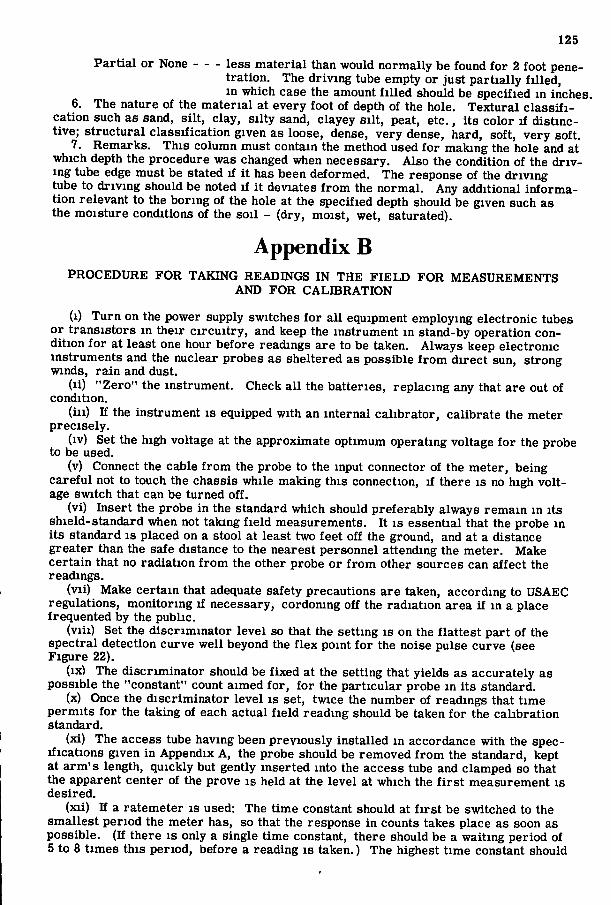
125
Part ia l or None less material than would normally be found for 2 foot penetration. The driving tube empty or just part ial ly f i l l ed , in which case the amount f i l l e d should be specified in inches.
6. The nature of the material at every foot of depth of the hole. Textural c lass i f i cation such as sand, si l t , clay, silty sand, clayey s i l t , peat, etc., i ts color if distinctive; structural classification given as loose, dense, very dense, hard, soft, very soft.
7. Remarks. This column must contain the method used for making the hole and at which depth the procedure was changed when necessary. Also the condition of the d r iv ing tube edge must be stated if i t has been deformed. The response of the driving tube to driving should be noted i f i t deviates f r o m the normal. Any additional information relevant to the boring of the hole at the specified depth should be given such as the moisture conditions of the soil - (dry, moist, wet, saturated).
Appendix B PROCEDURE FOR TAKING READINGS IN THE FIELD FOR MEASUREMENTS
AND FOR CALIBRATION
(i) Turn on the power supply switches for a l l equipment employing electronic tubes or transistors in their c i rcu i t ry , and keep the instrument in stand-by operation condition f o r at least one hour before readings are to be taken. Always keep electronic instruments and the nuclear probes as sheltered as possible f r o m direct sun, strong winds, ra in and dust.
(li) "Zero" the instrument. Check a l l the batteries, replacing any that are out of condition.
( i l l ) If the instrument is equipped with an internal calibrator, calibrate the meter precisely.
(iv) Set the high voltage at the approximate optimum operating voltage for the probe to be used.
(v) Connect the cable f r o m the probe to the input connector of the meter, being careful not to touch the chassis while making this connection, i f there is no high voltage switch that can be turned off.
(vi) Insert the probe in the standard which should preferably always remain in i ts shield-standard when not taking f i e ld measurements. I t is essential that the probe in its standard is placed on a stool at least two feet off the ground, and at a distance greater than the safe distance to the nearest personnel attending the meter. Make certain that no radiation f r o m the other probe or f r o m other sources can affect the readings.
(vii) Make certain that adequate safety precautions are taken, according to USAEC regulations, monitoring if necessary, cordoning off the radiation area i f in a place frequented by the public.
(vii i) Set the discriminator level so that the setting is on the flattest part of the spectral detection curve well beyond the f lex point fo r the noise pulse curve (see Figure 22).
(ix) The discriminator should be f ixed at the setting that yields as accurately as possible the "constant" count aimed fo r , for the particular probe in its standard.
(x) Once the discriminator level is set, twice the number of readings that time permits for the taking of each actual f i e l d reading should be taken fo r the calibration standard.
(xi) The access tube having been previously installed in accordance with the specifications given in Appendix A, the probe should be removed f r o m the standard, kept at arm's length, quickly but gently inserted into the access tube and clamped so that the apparent center of the prove is held at the level at which the f i r s t measurement is desired.
(xii) If a ratemeter is used: The time constant should at f i r s t be switched to the smallest period the meter has, so that the response in counts takes place as soon as possible. (If there is only a single time constant, there should be a waiting period of 5 to 8 times this period, before a reading is taken.) The highest time constant should
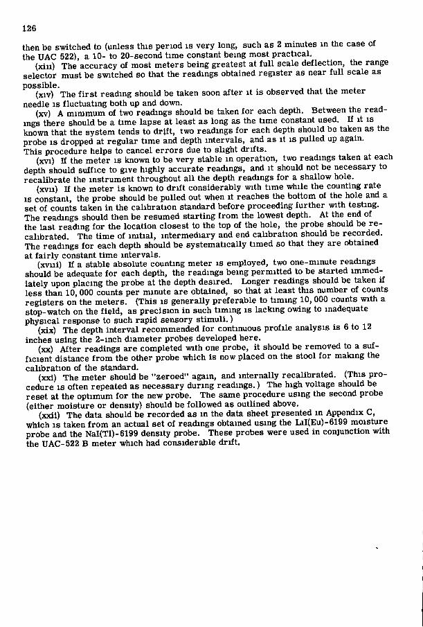
126
then be switched to (unless this period is very long, such as 2 minutes in the case of the UAC 522), a 10- to 20-second time constant being most practical.
(xiu) The accuracy of most meters being greatest at f u l l scale deflection, the range selector must be switched so that the readings obtained register as near f u l l scale as possible.
(xiv) The f i r s t reading should be taken soon after i t is observed that the meter needle is fluctuating both up and down.
(xv) A minimum of two readings should be taken for each depth. Between the readings there should be a time lapse at least as long as the time constant used. If i t is known that the system tends to d r i f t , two readings fo r each depth should be taken as the probe I S dropped at regular time and depth intervals, and as i t is pulled up again. This procedure helps to cancel er rors due to slight d r i f t s .
(xvi) If the meter is known to be very stable in operation, two readings taken at each depth should suffice to give highly accurate readings, and i t should not be necessary to recalibrate the instrument throughout a l l the depth readings for a shallow hole.
(xvii) If the meter is known to d r i f t considerably with time while the counting rate is constant, the probe should be pulled out when i t reaches the bottom of the hole and a set of counts taken in the calibration standard before proceeding fur ther with testing. The readings should then be resumed starting f r o m the lowest depth. At the end of the last reading for the location closest to the top of the hole, the probe should be re calibrated. The time of imt ia l , intermediary and end calibration should be recorded. The readings for each depth should be systematically timed so that they are obtained at f a i r l y constant time intervals.
(xviii) If a stable absolute counting meter is employed, two one-minute readings should be adequate fo r each depth, the readings being permitted to be started immediately upon placing the probe at the depth desired. Longer readings should be taken if less than 10, 000 counts per minute are obtained, so that at least this number of counts registers on the meters. (This is generally preferable to t iming 10,000 counts with a stop-watch on the f i e l d , as precision in such t iming is lacking owing to inadequate physical response to such rapid sensory s t imul i . )
(xix) The depth interval recommended fo r continuous prof i le analysis is 6 to 12 inches using the 2-inch diameter probes developed here.
(xx) After readings are completed with one probe, i t should be removed to a sufficient distance f r o m the other probe which is now placed on the stool fo r making the calibration of the standard.
(xxi) The meter should be "zeroed" again, and internally recalibrated. (This procedure is often repeated as necessary during readings.) The high voltage should be reset at the optimum for the new probe. The same procedure using the second probe (either moisture or density) should be followed as outlined above.
(xxii) The data should be recorded as in the data sheet presented m Appendix C, which I S taken f r o m an actual set of readings obtained using the LiI(Eu)-6199 moisture probe and the NaI(Tl)-6199 density probe. These probes were used in conjunction with the UAC-522 B meter which had considerable d r i f t .
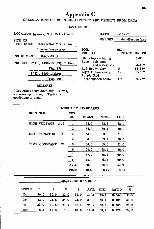
127
Appendix C CALCULATIONS OF MOISTURE CONTENT AND DENSITY FROM DATA
DATA SHEET
LOCATION Newark, N. J. McClellan St.
SITE OF TEST HOLE Intersection McClellan-
Freylinghusen Ave.
INSTRUMENT UAC-522 B
PROBES 2" D . , 6199-NaI(Tl), 7" Geom.
(Fig. 13)
2" D . , 6199-LiI(Eu)
(Fig. 20)
REMARKS
After ra in on previous day. Humid, warming up. Sunny. Typical soil conditions of area.
DATE 5-13-57
REPORT Linden-Bergen Line
SOIL HOR, PROFILE SURFACE DEPTH Black top surfacing 0-8" Base - sub-base
and sub-grade 8-15" Red-Brown clay " B i " 15-56" Light-Brown sandy "B2" 56-60" Purple-Red
decomposed shale "C" 60-72"
MOISTURE STANDARDS SETTINGS REP.
NO. START INTER. END
HIGH VOLTAGE 1145 1 58.0 58.8 62.0 2 58.0 59. 1 59.0
DISCRIMINATOR 27 3 58.0 59.0 61.0
4 58.0 59. 1 60.0
TIME CONSTANT 20 5 58.0 59.0 61.0
6 58.0 58.9 56.0
7 57.7 58.8 60.0 8 58.0 58.8 60.0
AVG. 58.0 58.9 59.9
TIME 10:20 10:27 10:33
MOISTURE READINGS
moist DEPTH 1 2 3 4 AVG. STD. RATIO %
24" 30.0 30.0 32.0 33.0 31.2 59. 5 0. 532 44.0 36" 22.0 23. 5 24.0 23.0 23.1 59.1 0.394 31.0 48" 22.0 20. 5 21. 5 22.0 21. 5 58.6 0.366 27.8 60" 19. 8 19.0 18. 5 18. 6 19.0 58.2 0.326 24.0
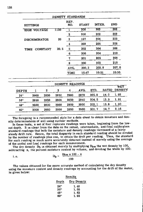
128
DENSITY STANDARDS
REP. SETTINGS NO. START INTER. END
HIGH VOLTAGE 1160 1 200 203 203
2 200 202 203
DISCRIMINATOR 20 3 197 204 205
4 202 205 208
TIME CONSTANT 20. 5 5 202 204 208
6 200 204 210
7 201 205 209
8 200 203 210
AVG. 200.3 203.8 207.0
TIME 10:47 10:51 10:55
DENSITY READINGS WET
DEPTH 1 2 3 4 AVG. STD. RATIO DENSITY
24" 2900 2850 2850 2900 2870 205.8 14.0 1.92
36" 2850 2850 2800 2850 2840 204. 5 13.9 1.91
48" 2800 2800 2800 2800 2800 203.1 13.8 1.90
60" 3000 2950 2950 2950 2960 201.7 14.7 2.16
The foregoing is a recommended style f o r a data-sheet to obtain moisture and density determinations of soil using nuclear methods.
In these tests, a set of four replicate readings were taken, beginning f r o m the lowest depth. I t I S clear f r o m the data on the in i t ia l , intermediate, and f ina l calibration standard readings that both the moisture and density readings increased at a f a i r l y Steady d r i f t rate. Hence, the total disparity in each standard reading should be divided by the number of readings plus one, to obtain the d r i f t per reading. Thus, the standard fo r each reading is much more accurately obtained instead of merely using the average of the in i t i a l and f ina l readings f o r each measurement.
The dry density Dfo is obtained merely by multiplying Dbw the wet density by 100, subtracting x, the percent moisture content by volume, and dividing the whole by 100:
i . e Dij = X 100 - X
100
The values obtained for the more accurate method of calculating the dry density using the moisture content and density readings by accounting for the d r i f t of the meter, is given below:
Results
Depth
24" 36" 48" 60"
Dry Density
1.48 1.60 1.62 1.92

129
The columns l is t ing the percent moisture and the wet density are simply obtained f r o m the calibration curves given in Figures 21 and 18 respectively.
It is to be noted that if the signal to noise ratio is significantly different fo r the in i t ia l and f ina l standard readings during a test, more accurate results w i l l be obtained by determining the proportion of noise and deducting the noise counts f r o m each reading as well as f r o m the standard. Such signal/noise ratios are obtained by making counts versus discriminator bias curves as in Figures 22 and 25.
References 1. Adair, R. K . , "Neutron Cross-Sections of the Elements, " Rev. Mod. Phys.,
22, pp. 249-289 (1950). 2. Albrecht, H. O. and MandeviUe, C. E . , "Crystals for the Scintillation Geiger
Counter," Pys. Rev, 81, p. 163 (1951). 3. Allen, J. S., "After-Pulses in Photomultiplier Tubes, " LA-1459 (1952). 4. Anger, H. O. , "Scintillation Counters fo r the Measurement of Radioactive
Samples," UCRL-886 (1951). 5. Ashkin, J . , "Experimental Nuclear Physics," Wiley, N . Y . (1953). 6. ASTM Special Technical Publication No. 134, "Symposium on the Use of Radio
isotopes in Soil Mechanics" (1952). (a) Hosticka, H. E . , "Radioisotopes and Nuclear Reactions Applied to Soil
Mechanics Problems". (b) Belcher, D. J . , Herner, R. C. , Cuykendall, T. R. and Sack, H. S., "Use of
Radioactive Material to Measure Soil Moisture and Density." (c) Lane, D. A . , Torchinsky, B. B. and Spinks, J. W. T. , "Determining Soil
Moisture and Density by Nuclear Radiations. " 7. Belcher, D . J . , Cuykendall, T. R. and Sack, H. S., "The Measurement of Soil
Moisture and Density by Neutron and Gamma Ray Scattering," C. A. A. Tech. Development Report No. 127 (1950).
8. Belcher, D. J . , Cuykendall, T. R. and Sack, H. S., "Nuclear Meters f o r Measuring Soil Density and Mositure in Thin Surface Layers, " C. A. A. Tech, Development Report No. 161 (1952).
9. Belcher, D. J. and Associates, Final Report, "The Determination of Moisture and Density Using Nuclear Instruments at the East Branch Dam, Clarion River, Pennsylvania" (1953).
10. Be l l , P. R . , "Use of Anthracene as a Scintillation Counter, " Phys. Rev., 73, p. 1405 (1948).
11. Berdan, D. and Bernhard, R. K . , "Pi lot Studies of Soil Density Measurements by Means of X-Rays ," Proc. ASTM 50 (1950).
12. Bernhard, R. K. and Chasek, M . , "Soil Density Determination by Means of Radioactive Isotopes," Nondestructive Testing, p. 17-23 (1953).
13. Bernhard, R. K. and Chasek, M . , "Soil Density Determination by Direct Transmission of Gamma Rays, " Preprint ASTM (1955).
14. Bernstein, W. and Schardt, A. W . , "Activation of L i l Crystal Phosphors," Phys. Rev., 85, p. 919, "A Scintillation Neutron Detector," ibid, 85, p. 711 (1952).
15. Bi rks , J. B . , "The Specific Fluorescence of Anthracene and other Organic Mater ia l s , " Phys. Rev. 84, p. 364 (1951).
16. B i rks , J. B . , "Scintillation Counters, " Pergammon Press, London (1953). 17. Bistline, J . , "Some Properties of BFa m Ionization Chambers, " Rev. Sci.
Ins t r . , 19, p. 842 (1948). 18. Bittman, L . et a l . , "Decay Time, Fluorescence Efficiencies, and Energy
Storage Properties of Various Substances with Y-Ray or o-Part icle Exci ta t ion," Phys. Rev., 87, p. 83 (1952).
19. Blau, M . and Dreyfus, B . , "The Mult ipl ier Photo-Tube m Radioactive Measurements, " Rev, Sci. Ins t r . , 16, p. 245 (1945).
20. Bonanomi, J. and Rossel, J . , "Studies of Scintillations of Alkaline Halides, " Helv. Phys. Acta, 24, p. 310 (1954).
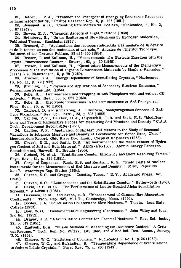
130
21. Botden, T. P. J . , "Transfer and Transport of Energy by Resonance Processes in Luminescent Solids, " Philips Research Rep. 6, p. 425 (1951).
22. Bousquet, A. G. , "Counting Rate Meters vs. Scalers, " Nucleonics, 4, No. 2, p. 67 (1949).
23. Bowen, E. J . , "Chemical Aspects of L igh t , " Oxford (1949). 24. Brimberg, S., "On the Scattering of Slow Neutrons by Hydrogen Molecules,"
Published Thesis. Stockholm (1956). 25. Brocard, J . , "Applications des isotopes radioactifs a la mesure de la densite
et de la teneur en eau des materiaux et des sols ," Annales de I 'Institut Technique Batiment et des Travaux Publics, 88:427-450 (1954).
26. Broser, I . and Kallman, H . , "Measurements of a-Particle Energies with the Crystal Fluorescence Counter, " Nature, 163, p. 20 (1949).
27. Broser, I . and Kallman, H . , "Quantitative Measurements of the Elementary Processes of the Excitation of Light in Luminescent Materials by Single a-Part icles ," (Trans.) Z. Naturforsch, 5, p. 79 (1950).
28. Brucker, G J . , "Energy Dependence of Scintillating Crystals, " Nucleonics, 10, No. 11, p. 72 (1952).
29. Bruining, H . , "Physics and Applications of Secondary Electron Emission, " Pergammon Press Ltd. (1954).
30. Bube, R . , "Luminescence and Trapping in ZnS Phosphors with and without CU Act iva tor ," Phys. Rev., 80, p. 655 (1950).
31. Bube, R. , "Electronic Transitions in the Luminescence of ZnS Phosphors, " Phys. Rev., 90, p. 70 (1953).
32. Caldwell, D. and Armstrong, J . , "Uni form, Nonhydrogenous Screens of ZnS-Type Phosphors, " Rev. Sci. Ins t r . , 23, p. 508 (1952).
33. Carlton, P. F . , Belcher, D . J . , Cuykendall, T. R. and Sack, H.S. "Modif ications and Tests of Radioactive Probes fo r Measuring Soil Moisture and Density." C.A.A. Tech. Development Report #194 (1953).
34. Carlton, P. F. "Application of Nuclear Soil Meters to the Study of Seasonal Variations in Subgrade Moisture and Density at Lockbourne A i r Force Base, Ohio." Memorandum Report, Ohio River Div. Labs., Corps of Engineers (1955).
35. Church, G. R. , and Smith, D. B. "An Instrument fo r the Measurement of Hydrogen Content of Soil and Bulk Mate r i a l . " AERE-I/R-1687. Atomic Energy Research Establishment, Harwell, Gt, Br i t a in (1955).
36. Cleland, M . et al . "Scintillation Counter Efficiency and Short Resolving T imes . " Phys. Rev., 81, p. 324 (1951).
37. Corps of Engineers. Rush, E. S. and Remhart, K. G. "Fie ld Tests of Nuclear Instruments fo r the Measurement of Soil Moisture and Density. " Misc. Paper No. 3-117. Waterways Exp. Station (1954).
38. Curran, S. C. and Craggs. "Counting Tubes." N. Y . , Academic Press, Inc. (1949).
39. Curran, S. C. "Luminescence and the Scintillation Counter. " Butterworth (1953). 40. Davis, R. H. et al . "The Performance of Lucite-Bonded Alpha Scintillation
Screens." AD-299(I) (1951). 41. Davisson, C M . , and Evans, R .D. "Measurement of Gamma-Ray Absorption
Coefficients." Tech. Rep. #37, M . I . T . , Cambridge, Mass. (1950). 42. Dooley, J. A. "Scintillation Counters for Slow Neutrons." Thesis. Iowa State
College (1953). 43. Dow, W. G. "Fundamentals of Engineering Electronics. " John Wiley and Sons,
2nd Ed. (1952). 44. Draper, J. E. "A Scintillation Counter for Thermal Neutrons." Rev. Sci. Ins t r . ,
22, p. 543 (1951). 45. Eastwell, B . A. " In situ Methods of Measuring Soil Moisture Content - A C r i t i
cal Resume." Tech. Rep. No. W/T27. B r . Elec, and All ied Ind. Res. Assoc., Survey, U . K . (1953).
46. Elmore, W. C. "Statistics of Counting. " Nucleomcs 6, No. 1, p. 26 (1950). 47. Elmore, W. C. , and Hofstadter, R. "Temperature Dependence of Scintillations
in Sodium Iodide Crystals ," Phys. Rev. 75, p. 203 (1949).
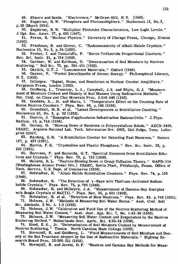
131
48. Elmore and Sands. "Electronics." McGraw-Hil l , N. Y. (1949). 49. Engstrom, R. W. "Phosphors and Photomultipliers. " Nucleonics 12, No. 3,
p. 26 (March 1954). 50. Engstrom, R. W. "Mult ipl ier Phototube Characteristics, Low Light Levels. "
J. Opt. Soc. Amer. 37, p. 420 (1947). 51. Fermi , E, "Nuclear Physics." University of Chicago Press, Chicago, I l l inois
(1950). 52. Friedman, H. and Glover, C. "Radiosensitivity of Alkali-Halide Crystals ."
Nucleonics 10, No. 6, p. 24 (1952). 53. Fowler, I . and Tunnicliffe, P. "Boron Tr i f luor ide Proportional Counters. "
Rev. Sci. Instr. 21, p. 734 (1950). 54. Gardner, W. and Kirkham, D. "Determination of Soil Moisture by Neutron
Scattering," Soil Sci. 73, pp. 391-401 (1952). 55. Garlick, G. F . J. "Luminescent Mater ia l s . " Oxford (1949). 56. Gaynor, F. "Pocket Encyclopedia of Atomic Energy. " Philosophical Library ,
N . Y . (1950). 57. Gillespie. "Signal, Noise, and Resolution in Nuclear Counter A m p l i f i e r s . "
Pergamon Press, London (1953). 58. Goldberg, I . , Trescony, L . J . , Campbell, J. S. and Whyte, G. J. "Measure
ment of Moisture Content and Density of Soil Masses Using Radioactive Methods. " Nat. Conf. on Clays and Clay Minerals Proc. 3:516-548 (1955).
59. Goodwin, A . , Jr. and Mario, I . "Temperature Effect on the Counting Rate of Boron Neutron Counters. " Phys. Rev. 88, p. 168 (1952).
60. Greenblatt, M . H. et a l . "Latest Developments in Scintillation Counting." Nucleonics 10, No. 3, p. 32 (1952),
61. Gueron, J, "Examples d'applications Industrialles Radioactivite, " J. Phys. Radium. 15, p. 74A (1954).
62. Gurney, G. "Slowing Down of Neutrons m Polycrystalline Solids." AECD-2449, USAEC, Argonne National Lab, Tech, Information Div. ORE, Oak Ridge, Tenn, Lithopr int (1947).
63. Harding, G. N. " A Scintillation Counter for Detecting Fast Neutrons," Nature 167, p, 437 (1951),
64. Harr is , F. K, "Crystalline and Plastic Phosphors." Rev. Sci. Instr. 22, p. 223 (1951).
65. Harrison, F. and Reynolds, G. T, "Spectral Emission f r o m Scintillation Solutions and Crystals ." Phys. Rev. 79, p. 732 (1950).
66. Hallens, R. L . "Neutron Slowing Down in Group Diffusion Theory." WAPD-114 (Westinghouse Atomic Power D i v . ) USAEC, Bettis Plant, Pittsburgh, Penna, Office of Tech. Service, U. S. Dept. of Commerce (1956).
67. Hofstadter, R. "Alka l i Halide Scintillation Counters." Phys, Rev, 74, p. 100 (1948).
68. Hofstadter, R. "The Detection of -y -Rays with Thallium-Activated Sodium Iodide Crystals. " Phys. Rev, 75, p, 796 (1949).
69. Hofstadter, R, and Mclntyre, J. A. "Measurement of .Gamma-Ray Energies with Single Crystals of N a l ( T l ) . " Phys. Rev. 80, p. 631 (1950).
70. Hofstadter, R. et a l . "Detection of Slow Neutrons," Phys, Rev. 82. p, 749 (1951). 71. Holmes, J. W. "Methods of Measuring Soil Water Status," Aust, Conf. Soil
Sci. Adelaids. 2 No. 4, 1:3 (1953). 72. Holmes, J. W. "Calibration and Field Use of the Neutron Scattering Method of
Measuring Soil Water Content." Aust. Jour, App, Sci. 7, No. 1:45-58 (1956). 73. Holmes, J. W. "Measuring Soil Water Content and Evaporation by the Neutron
Scattering Method." Netherlands Jour. Agric . Sci. 4:30-34 (1956). 74. Hood, E. E . , Jr. "Determination of Soil Moisture Content by Measurement of
Neutron Scattering, " Thesis, North Carolina State College (1953), 75. Horonjeff, R. and Goldberg, L . "Fie ld Measurements of Soil Moisture and Den
sity at the San Francisco Airpor t by the Use of Radioactive Materials, " Highway Research Board Proc, 32:500-511 (1953).
76. Horonjeff, R. and Javete, D. F. "Neutron and Gamma-Ray Methods for Meas-
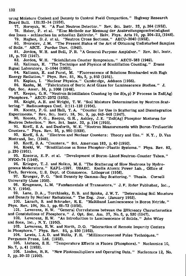
132
uring Moisture Content and Density to Control Field Compaction." Highway Research Board Bu l l . 122:23-34 (1956).
77. Hornyak, W. " A Fast Neutron Detector. " Rev. Sci. Instr. 23, p. 264 (1952). 78. Huber, P. et a l . "Eine Methode zur Messung der Ausbreitungsgeschwindigkeit
des lonen - schlauches im schnellan Zahlrohr. " Helv. Phys. Acta 19, pp. 204-2U, (1946). 79. Hughes, D. J. et al . "Neutron Cross Sections. " AECU-2040 (1952). 80. Hvorslev, J. M . "The Present Status of the A r t of Obtaining Undisturbed Samples
of Soils. " ASCE. Purdue Univ. (1940). 81. Jordon, W. H. and Be l l , P. R. " A General Purpose A m p l i f i e r . " Rev. Sci. Instr.
18, p. 703 (1947). 82. Jordon, W . H . "Scintillation Counter Symposium. " AECU-583 (1949). 83. Kallman, H. "The Technique and Physics of Scintillation Counting." Evans
Signal Laboratory, E-1044 (1950). 84. Kallman, H. and Furst, M . "Fluorescence of Solutions Bombarded with High
Energy Radiation. " Phys. Rev. 81, No. 5, p. 853 (1951). 85. Kaplan, I. "Nuclear Physics." Cambridge, Addison (1956). 86. Kasha, M . "Fabrication of Boric Acid Glass fo r Luminescence Studies. " J.
Opt. Soc. Amer. 38, p. 1068 (1948). 87. Keepin, G. R. "Neutron Scintillation Counting by the S(n, p) P Process in ZnS(Ag)
Phosphors." AECU-2372 (1952). 88. Knight, A. H. and Wright, T. W. "Soil Moisture Determination by Neutron Scat
tering. " Radioisotopes Conf. 2:111-122 (1954). 89. Koontz, P. G. and Hall , T. A. "Counter for Use in Scattering and Disintegration
Experiments." Rev. Sci. Instr. 18, No. 9, pp. 643-646 (1947). 90. Koontz, P. G. , Keepin, G. R. , Ashley, J. E. "ZnS(Ag) Phosphor Mixtures for
Neutron Detection." Rev. Sci. Instr. 32, p. 154 (1955). 91. Korf f , S. A. and Danforth, W. E. "Neutron Measurements with Boron-Tri f luor ide
Counters. " Phys. Rev. 55, p. 980 (1939). 92. Korf f , S. A. "Electron and Nuclear Counters: Theory and Use." N . Y . , D . Van
Nostrand, Inc. (1948). 93. Korf f , S. A. "Counters. " Sci. American 183, p. 40 (1950). 94. Koski, W. "Scintillations in Some Phosphor-Plastic Systems." Phys. Rev. 82,
p. 230 (1951). 95. Kozoriz, E. P. et a l . "Development of Boron-Lined Neutron-Counter Tubes,"
NYOO-74 (1949). 96. Krieger, T. J. and Nelkin, M . S. "The Scattering of Slow Neutrons by Hydro
genous Moderators." KAPL-1597. USAEC. Knolls Atomic Power Lab. , Office of Tech. Services, U. S. Dept. of Commerce. Lithoprint (1956).
97. Krueger, P. G. "Soil Density by Gamma-Ray Scattering. " Thesis. Cornell University (June 1950).
98. Krugmann, L . M . "Fundamentals of Transis tors ." J. F. Rider Publisher, Inc. , N . Y . (1954).
99. Lane, D. A . , Torchinsky, B . B. and Spinks, J. W. T. "Determining Soil Moisture and Density by Nuclear Radiations. " The Eng. Jour. (January 1953).
100. Larach, S. and Schrader, R. E. "Multiband Luminescence in Boron N i t r i d e . " Phys. Rev. 104, No. 1, pp. 68-73 (1956).
101. Leverenz, H. W. "General Correlations between the Efficiency Characteristics and Constitutions of Phosphors." J. Opt. Soc. Am. 37, No. 6, p. 520 (1947),
102. Leverenz, H. W. "An Introduction to Luminescence of Solids. " John Wiley and Sons, Inc. , N . Y . (1950).
103. Leverenz, H. W. and North, D. O. "Interaction of Remote Impurity Centers in Phosphors." Phys. Rev. 85, p. 930 (1952).
104. Lewis, I . A. D. and Wells, F. H. "Mill imicrosecond Pulse Techniques. " Pergamon Press, Ltd . (1953).
105. Liebson, S. H. "Temperature Effects in Fluors (Phosphors)." Nucleonics 10, No. 7, p. 41 (1952).
106. Linden, B. R. "New Photomultipliers and Operating Data. " Nucleomcs 12, No. 3, pp. 20-23 (1950).

133
107, Locher, G. L , "The Design and Construction of Reliable G-M Counters, " Phys, Rev, 55, p, 675 (1939),
108, Mar ine l l i , L , D, "Practical Aspects of Radioactivity Measurements, Calibration, " Nucleonics 8, No, 6, S-20 (1952),
109, Marshak, R, E, et al , "Introduction to the Theory of Diffusion and Slowing Down of Neutrons, " I , Nucleonics 3, No, 5, p. 10 (1949), I I , Nucleonics 3, No, 6, p,43 (1949). m . Nucleonics 4, No. 1, p. 53 (1949). IV, Nucleomcs 4, No. 2, p. 59 (1949),
110, Marchall , F, et al, "Photomultiplier Radiation Detector," Rev, Sci, Instr, 19, p. 744 (1948),
111, Miles, M . E, "Energy Distribution of Gamma-Rays Scattered Around a Soil Density Probe," Thesis, Cornell Univ, (1952),
112, Minarik, W, L , and Drickamer, H, G, "Temperature Coefficient of Scintillation Phosphors," Rev, Sci, Instr, 22, p. 704 (1951),
113, Mort ier , P. and DeBoodt, M . "Determination of Soil Moisture by Neutron Scattering." Neth. Jour, Agric, Sci. 4, pp, 111-113 (1956),
114, Morton, G, A. "Photomultipliers fo r Scintillation Counting." R.C. A, Review 10, F . 525 (1949),
115, Muelhause, C O , "Neutron Scintillation Counters," Nucleonics 14, No, 4, p, 38 (1956),
116, Owen, R .B . "A Review of Scintillation Counting." Atomics 4, p, 5 (1953), 117, Owen, R , B , and Sayle, E ,A. "Scintillation Counting Equipment. " Proc, Inst,
E ,E , 98, p. 245 (1951), 118, Pieper, G. F , , Jr. "The Measurement of Moisture Content of Soil by the Slow
ing of Neutrons. " Thesis. Cornell Umv. (1949). 119, Plesset, M , S , , Hastings, C, and Cohen, S, T, "Effects of Source and Shadow
Shield Geometry on the Scattering of Gamma Rays," RM-32. Rand Corporation. 120, Post, R. F . "Performance of Pulsed Photomultipl iers ." Nucleomcs 10, No.
5, p. 46 (1953). 121, Pringsheim, P. "Fluorescence and Phosphorescence. " N . Y , , Interscience
Publishers, Inc, (1949), 122, Rajchman, J, "Le courant residuel dans les multiplicateurs d'electrons-
electrostatiques, " Thesis, Geneva (1938), 123, Rann, W. H. "Amplif icat ion by Secondary Electron Emission. " J. Sci. Instr.
16, p. 241 (1939), 124, Reich, H. J. "Theory and Applications of Electron Tubes. " McGraw-Hil l ,
N. Y . , 1st Ed. (1939). 125, Reid, C. "Scintillators and Energy Transfer Processes," Phys. Rev. 88,
p,422 (1952). 126, Reynolds, G. T. "Liquid Scintillation Counters. " Nucleonics 6, No. 5, p. 68
(1950). 127, Reynolds, G.T. "Solid and Liquid Scintillation Counters, " Nucleonics 10,
No, 7, p, 46 (1952), 128, Robinson, L , and Arnold, J, "The Scintillation Counter, I. The Existence
of Plateaus," Rev, Sci, Instr, 20, p, 549 (1949), 129, Rohr, R, C, , Roher, E . R , , and Macklin, R, L , "Proportional Fission Neutron
Counters," Rev. Sci, Instr, 23, p. 595 (1952). 130, Rossi, B . and Staub, H. H. "Ionization Chambers and Counters. E3q)erimental
Techniques." McGraw-Hil l , N . Y . (1949). 131, Roy, S. E. " A Comparison of Certain Methods of Measuring Structural Rela
tionships of Soils ." Thesis. Penn, State Univ, Litho, (1956). 132, Roy, S. E. "Nuclear Radiation Methods for the Determination of Density and
Moisture Content of Soils. " Special Re. #1. Ins. Cond. Comm., A. I. E. E. Unpublished (1956).
133, Schenck, J. "Neutron Detecting Phosphors. " Nucleonics 10, No. 8, p. 54 (1952). 134, Schenck, J. and Heath, R. L . " T i n Activation of Lithium Iodide." Phys. Rev.
85, p. 923 (1952). 135, Segre, E. and Wiegand, C. "BFs Neutron Detector for Low Neutron Inten
s i t ies ," Rev. Sci. Instr. 18, p. 86 (1947).
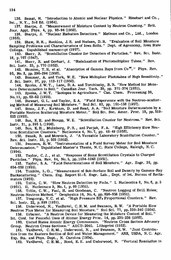
134
136. Semat, H. "Introduction to Atomic and Nuclear Physics." Rinehart and Co., Inc. , N . Y , , 3rd Ed. (1954),
137. Sharpe, J, "Measurement of Moisture Content by Neutron Counting," B r i t . Jour. Appl. Phys. 4, pp. 93-94 (1953).
138. Sharpe, J. "Nuclear Radiation Detectors." Methuen and Co., L t d , , London (1955),
139. Shaw, R. H , , Runkles, J. R. and Nielsen, D. R. "Evaluation of Soil Moisture Sampling Problems and Characteristics of Iowa Soils ." Dept. of Agronomy, Iowa State College. Unpublished manuscript (1957).
140. Sherr, R. "Scintillation Counter fo r Detection of Par t ic les ," Rev, Sci, Instr. 18, p,767 (1947).
141. Sherr, R. and Gerhart, J, "Stabilization of Photomultiplier Tubes." Rev. Sci. Instr. 23, p. 770 (1952).
142. Skimizu, T. H. et a l , "Absorption of Gamma Rays f r o m C o " Phys, Rev. 85, No. 2, pp, 290-294 (1952),
143. Sommer, A, and Turk, W, E. "New Mult ipl ier Phototubes of High Sensitivity," J, Sci, Instr, 27, pp, 113-117 (1950),
144. Spinks, J. W. T . , Lane, D. A. and Torchinsky, B . B, "New Method fo r Moisture Determination in Soi l , " Canadian Jour. Tech. 29, pp, 371-374 (1951).
145. Spinks, J. W. T, "Isotopes in Agr icu l tu re . " Can. Chem. Processing 39, No. 11, pp. 63-82 (1955).
146. Stewart, G. L . and Taylor, S. A. "Fie ld Experience with the Neutron-scattering Method of Measuring Soil Moisture. " Soil Sci. 83, pp. 151-158 (1957).
147. Stone, J. F . , Kirkham, D. and Read, A. A. "Soil Moisture Determination by a Portable Neutron Scattering Moisture Meter . " Soil Sci. Soc. Amer. Proc. 19, pp. 519-523 (1955).
148. Sun, K. H. and Shoupp, W. E. "Scintillation Counter for Neutrons," Rev. Sci. Instr, 21, p. 395 L (1950).
149. Sun, K, H , , Malmberg, P, R. , and Pecjak, F. A. "High Efficiency Slow Neutron Scintillation Counters." Nucleomcs 4, No, 7, pp. 46-49 (1956),
150. Swank, R. and Mownick, J. "A Versatile Laboratory Scintillation Counter." Rev. Sci. Instr, 23, p, 503 (1952),
151. Swanson, R. W. "Instrumentation of a Field Survey Meter fo r Soil Moisture Determination." Unpublished Master's Thesis, N , C. State College, Raleigh, N, C. (1954),
152. Taylor, C, J . , et a l . "Response of Some Scintillation Crystals to Charged Par t ic les ." Phys, Rev, 84, No, 5, pp, 1034-1043 (1951).
153. Taylor, S. A. "Fie ld Determinations of Soil Moisture. " Agr. Engr, 35, pp, 654-659 (1955),
154. Timbl in , L . O,, "Measurement of Sub-Surface Soil and Density by Gamma-Ray Backscattering," Chem, Eng, Report SI-6. Engr, Lab, , Dept, of Int, Bureau of Reclamation (1955),
155. Ti t t le , C. W. "Slow Neutron Detection by Foils . " L Nucleonics 8, No. 6, p. 5 (1951). n. Nucleonics 9, No. 1, p. 60 (1951).
156. Ti t t le , C. W. , Faul, H. and Goodman, C. "Neutron Logging of D r i l l Holes; Neutron-Neutron Method. " Geophysics 16, No, 4, pp, 626-658 (1951),
157. Tongiorgi, V. C. et a l . "High Pressure BFs Proportional Counters." Rev, Sci. Instr. 22, p. 899 (1951).
158. Underwood, N . , VanBavel, C. H. M . and Swanson, R.W. "A Portable Slow Neutron Flux Meter f o r Measuring Soil Moisture. " Soil Sci. 77, pp. 339-340 (1954).
159. Urbanec. "A Neutron Device for Measuring the Moisture Content of Soil. " Int, Conf. for Peaceful Uses of Atomic Energy Proc. 14, pp. 235-238 (1955),
160. United States Atomic Energy Commission. "Neutron Cross Section Advisory Group. Neutron Cross Sections." AECU-2040. Lithoprint (1952).
161. VanBavel, C. H, M . , Underwood, N . , and Swanson, R. W. "Joint Contribution f r o m the Eastern Section of Soil and Water Management," ARS, USDA, N, C. Agr. Exp. Sta. and Phys. Dept., N . Carolina (1954),
162. VanBavel, C. H. M , , Hood, E, E, and Underwood, N, "Ver t ica l Resolution in
135
the Neutron Method fo r Measuring Soil Moisture. " Trans. Amer, Geophysical Union, 35, No, 4, pp, 595-600 (1954),
163. VanBavel, C, H, M . , Underwood, N . , and Swanson, R. W, "Soil Moisture Measurement by Neutron Moderation." Soil Sci, 82, pp, 29-41 (1956),
164. VanBavel, C, H. M . "Neutron and Gamma Radiation as Applied to Measuring Physical Properties of Soil in its Natural State." 6th Inter. Cong. Soil Sci. Trans. B, pp. 355-360 (1956),
165. Vomocil, J. A, " In Situ Measurement of Soil Bulk Density, " Agr, Engr, 35, No. 9 (1954).
166. Wallace, P.R. and LeGaine, J. "Elementary Approximations in the Theory of Neutron Di f fus ion , " MT-12, Atomic Energy of Canada Limited, Chalk River P r o j ect, Research and Development. Chalk River, Ontario. Lithoprint (1943).
167. Wallace, P. R. "Neutron Distribution in Elementary Diffusion Theory. " L Nucleonics 3, No. 2, p. 30 (1949), H. Nucleonics 3, No, 3, p, 48 (1949),
168. Welton, T, A, and Goertzel, G. "Asymptotic Distribution of Neutrons f r o m a Point Source in a Medium Containing Hydrogen and an Isotropic Scatterer," AECD-2796 (Atomic Energy Commission Document), ASAEC. Oak Ridge National Lab. Tech. Information D i v , , O, R, E, Oak Ridge, Tenn, Lithoprint (1949).
169. Whitehouse, W. J . , and Graham, G. A. R. "Ratio of Neutron Absorption Cross-sections of Boron and Hydrogen." Canad, J, Res. 25A, pp. 261-275 (1947).
170. Wilkins, J. E . , J r . , Oppenheim, A. and Proiser, S. "Asymptotic Solutions fo r the Straight Ahead Transport Equation." NYO-639 (New York Operations). USAEC. Nuclear Development Associates, Inc. Tech. Information Service, Oak Ridge, Tenn. Lithoprint (1951).
171. Wilson, C. T, R, "On a Method of Making Visible the Paths of Ionizing Particles through a Gas." Proc, Roy, Soc. (London) 85, p. 285 (1911),
172. Yates, E. P. "Soil Moisture Determination by Neutron Scattering." Unpublished Thesis. Cornell Univ. (Sept, 1950),
173. Zweifel , P, F . and Bigelow, S. R, "Numerical Solution of the Neutron Slowing Down Problem in the Presence of Hydrogen." KAPL-1278, USAEC, Knolls Atomic Power Lab. , Schenectady (1955).
174. Zworykin, V, K, et a l . "The Secondary Emission Mult ipl ier - A New Electronic Device," Proc. I. R. E. 24, P. 351 (1936).
EgB:0Jl-90