Embed Size (px)
Citation preview

SCIENCE & TECHNOLOGY
1
Development and Calibration of the ART-XC Mirror Modules for the Spectrum Rontgen Gamma
Mission
• B. Ramsey1, M.Gubarev1, R.Elsner1, J.Kolodziejczak1, S.O’Dell1, D.Swartz1*
• M. Pavlinsky2, A. Tkachenko2, I. Lapshov2
1 NASA Marshall Space Flight Ctr., Huntsville, USA - * USRA2 IKI, Moscow, Russia
https://ntrs.nasa.gov/search.jsp?R=20140006455 2018-08-22T10:31:10+00:00Z

SCIENCE & TECHNOLOGY
2
SRG Overview
Parameter ART eROSITA
Energy Range 5-30 keV 0.2-12 keVEffective Area 455 cm2 at 8 keV 2500 cm2 at 1 keVField of View 32 arcmin 1 degSystem Angular Resolution (on axis)
1 arcmin 15 arcsec
Energy Resolution 1.4 keV at 14 keV 130 eV at 6 keV
The Spectrum-Röntgen-Gamma (SRG) mission is a Russian-lead X-ray astrophysical observatory that carries two co-aligned X-ray telescope systems.
The primary instrument is the German-led extended ROentgenSurvey with an Imaging Telescope Array (eROSITA), a 7-module X-ray telescope system that covers the energy range from 0.2-12 keV.
The complementary instrument is the Astronomical Roentgen Telescope – X-ray Concentrator (ART-XC or ART), a 7-module X-ray telescope system that provides higher energy coverage, up to 30 keV.
eROSITAART-XC

SCIENCE & TECHNOLOGY
3
ART-XC Optics Configuration
Parameter Value
Number of Mirror Modules 7=4+3
Number of Shells per Module 28
Shell Coating > 10 nm of iridium (> 90% bulk density)
Shell Total Length, inner and outer diameters
580 mm, 50 mm, 150 mm
Encircled Half Energy Width Less than 1 mm diameter, center of field of viewLess than 2.5 mm diameter, 15 arcmin off axis
Mirror Module Effective Area ≥ 65 cm2 at 8 keV (on axis)
Module Focal Length 2700±1 mm
MSFC has designed and is fabricating four ART x-ray optics modules under an International Reimbursable Agreement between NASA and with IKI (delivery – February 2014)three + one spare ART modules under Agreement regarding Cooperation on the ART-XC Instrument onboard the SRG Mission between NASA and IKI (delivery – March 2014)
Schematic representation of the ART-XC instrument

SCIENCE & TECHNOLOGY
4
Mechanical Design
One spider design permits increasing the thickness of outer shells for given weight budget (15 kg / Module)
Shells are electroformed NiCo, 250 – 325 microns thick
SCIENCE & TECHNOLOGY
5
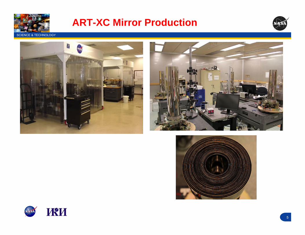
ART-XC Mirror Production

SCIENCE & TECHNOLOGY
6
ART-XC Mirror Status
All shells fabricated for 1st four module
75% of shells fabricated for 2nd four modules
Qualification (engineering) unit tested and delivered to IKI
1st flight module undergone extended x-ray calibration
2nd module under calibration now

SCIENCE & TECHNOLOGY
7
ART-XC: MSFC Test Facility
MSFC STRAY LIGHT FACILITY
• ~ 104 m Beamline• 1-m diameter main tube• 3m x 10m instrument chamber
• FOR ART testing:• Bell housing for smaller, shorter-focal-length optics• Contains Tip, Yaw and linear stages all computer controlled• Cu x-ray source system, 50kV, 1 mA, 0.5 mm spot

SCIENCE & TECHNOLOGY
8
ART-XC: MSFC Test Facility
CdTe Detector
• 5 x 5 x 1 mm• High rate capability
(>105 c/s)• Series of laser-cut W
pinholes
CCD Camers
• 2k x 2k pixels• 13.5 micron each• Frame / sec readout
capability

SCIENCE & TECHNOLOGY
9
Three inner shells (1,2,4)
Three outer shells (25,26,27)
Three mass simulators to replace missing shells (diameters are 74, 101.3 and 126.4 mm)
Qualification Unit
Qualification unit with handling fixture mounted on the shipping base

SCIENCE & TECHNOLOGY
10
ART-XC: Qualification Unit
Effective area and resolution of qualification unit measured as follows:
• Initial test• Post vibration test #1• Post thermal (survival temperatures) test• Post acoustic test• Post module modification (stabilizers added)• Post vibration test #2• Final (post shock test)
SCIENCE & TECHNOLOGY
11
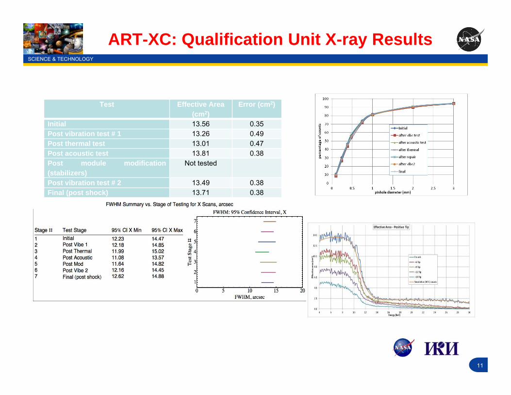
ART-XC: Qualification Unit X-ray Results
Test Effective Area (cm2)
Error (cm2)
Initial 13.56 0.35Post vibration test # 1 13.26 0.49Post thermal test 13.01 0.47Post acoustic test 13.81 0.38Post module modification(stabilizers)
Not tested
Post vibration test # 2 13.49 0.38Final (post shock) 13.71 0.38

SCIENCE & TECHNOLOGY
12
Flight Unit X-ray Calibration Requirements
CCD CAMERA
Point Spread Function (PSF) – FIRST MODULE Measure the PSF at each focus position and off-axis angle listed below:
NOMINAL FOCUSOffset angles (36 measurements)Range: -18, -12, -7, -3, 0, 3, 7, 12, 18 arcmin at four different azimuthal angles: 0, 45, 90, 135
NOMINAL – 7 MMOffset angles (68 measurements)Range: -18, -15, -12, -9, -7, -5, -3, -1, 0, 1, 3, 5, 7, 9, 12, 15, 18 arcmin at four different azimuthal angles: 0, 45, 90, 135
NOMINAL – 15 MMOffset angles (36 measurements)Range: -18, -12, -7, -3, 0, 3, 7, 12, 18 arcmin at four different azimuthal angles: 0, 45, 90, 135
Point Spread Function (PSF) – REMAINING MODULES Measure the PSF at each off-axis angle listed below:
NOMINAL – 7 MMOffset angles (68 measurements)Range: -18, -15, -12, -9, -7, -5, -3, -1, 0, 1, 3, 5, 7, 9, 12, 15, 18 arcmin at four different azimuthal angles: 0, 45, 90, 135

SCIENCE & TECHNOLOGY
13
Flight Unit X-ray Calibration (CCD)
• M1 Half Power Diameter vs. Off-Axis Angle for Several Focus Positions
– Field of view with HPD < flight pixel size expands with de-focus
– 7 mm defocus position is preferred for flight for best survey sensitivity
• M1 vs. M2 Half Power Diameter vs. Off-Axis Angle at Preferred Focus Position
– Modules are very similar– Repeatability of calibration results confirmed

SCIENCE & TECHNOLOGY
14
Flight Unit X-ray Calibration (CCD)
True-to-scale images at 7mm from focus, as a function of off-axis angle in arcmin

SCIENCE & TECHNOLOGY
15
Flight Unit X-ray Calibration (CCD)
Comparison of on-axis and 18 arcmin off-axis raw imagesOff-axis image shows extended wing structure due to singly reflected x-raysVertical line below on-axis image is an artifact of CCD readout smear -- removed in analysisX-rays from 8 keV Cu-K lines1 pixel = 2 arcsec

SCIENCE & TECHNOLOGY
16
Technology
Flight Unit X-ray Calibration (CCD)
PSF on axis
FWHM on axis

SCIENCE & TECHNOLOGY
17
Modeled Stray Light
Modeled stray light reaching the detector on orbit, in terms of brightest pixel. Curves represent (double reflected (black) and singles from the P (blue) and H (red) segments. Straight-throughs are depicted in gray.

SCIENCE & TECHNOLOGY
18
Flight Unit X-ray Calibration (CdTe)
On axis measurements
SCIENCE & TECHNOLOGY
19
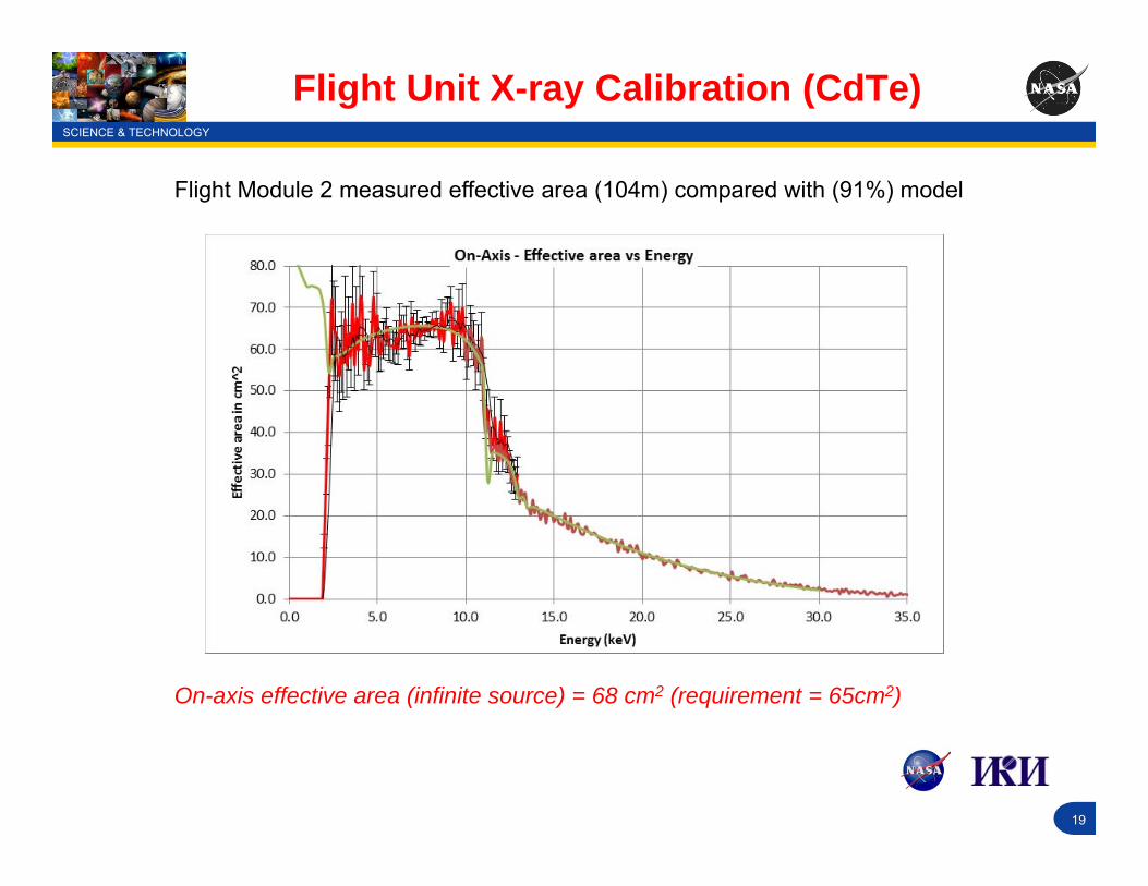
Flight Unit X-ray Calibration (CdTe)
On-axis effective area (infinite source) = 68 cm2 (requirement = 65cm2)
Flight Module 2 measured effective area (104m) compared with (91%) model

SCIENCE & TECHNOLOGY
20
Flight Unit X-ray Calibration (Comparison)
Reasonably good agreement between CCD and CdTe

SCIENCE & TECHNOLOGY
21
Flight Unit X-ray Calibration: CONCLUSION
ART-XC Flight Module Calibration and data processing has begun
CCD and CdTe data agree well
The first two modules meet effective area requirement (65 cm2 / module @ 8 keV) and greatly exceed angular resolution requirement (30 arcsec, defocused, vs ~ 60 arcsec)
Calibration will be concluded by late February / early March 2014
SCIENCE & TECHNOLOGY
22
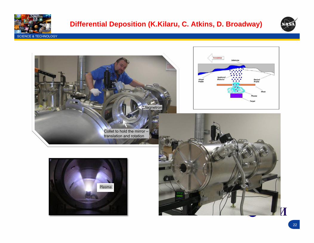
Differential Deposition (K.Kilaru, C. Atkins, D. Broadway)
Collet to hold the mirror –translation and rotation
Magnetron

SCIENCE & TECHNOLOGY
23
Stress Measurement in Coatings (D. Broadway)
Our Method: We exploit the known spherical deformation and infer the substrate curvature by measuring the sag of the wafer (just one point).
Methods of In-Situ Stress Measurement: All aim to measure the change in curvature of the substrate from which stress is calculated from the Stoney equation: κ


![Sh - [∫] [∫] She sells sea shells at the sea shore. The shells she sells are surely sea shells. So if she sells shells on the seashore, I'm sure she sells](https://img.pdfslide.us/doc/110x75/56649f165503460f94c2b775/sh-she-sells-sea-shells-at-the-sea-shore-the-shells-she-sells.jpg)