Embed Size (px)
Citation preview
Science and Technology of
Miniaturization of Subtractive and
Additive Manufacturing Process
Ramesh Singh
Machine Tools Lab
Department of Mechanical Engineering
Indian Institute of Technology Bombay
1
• Micromanufacturing: Motivation & Background
• Novel Subtractive Micromachining
– Ultra-high Speed Micromachining
– Laser Assisted Mechanical Micromachining
– Micro-Electrical Discharge Machining
• Additive Micromanufacturing
• Summary
2
3
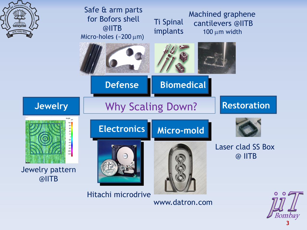
Defense
Micro-mold Electronics
Biomedical
Why Scaling Down?
Ti Spinal
implants
Safe & arm parts
for Bofors shell
@IITB Micro-holes (~200 mm)
Hitachi microdrive
Restoration Jewelry
Jewelry pattern
@IITB
Laser clad SS Box
@ IITB
www.datron.com
Machined graphene
cantilevers @IITB 100 mm width
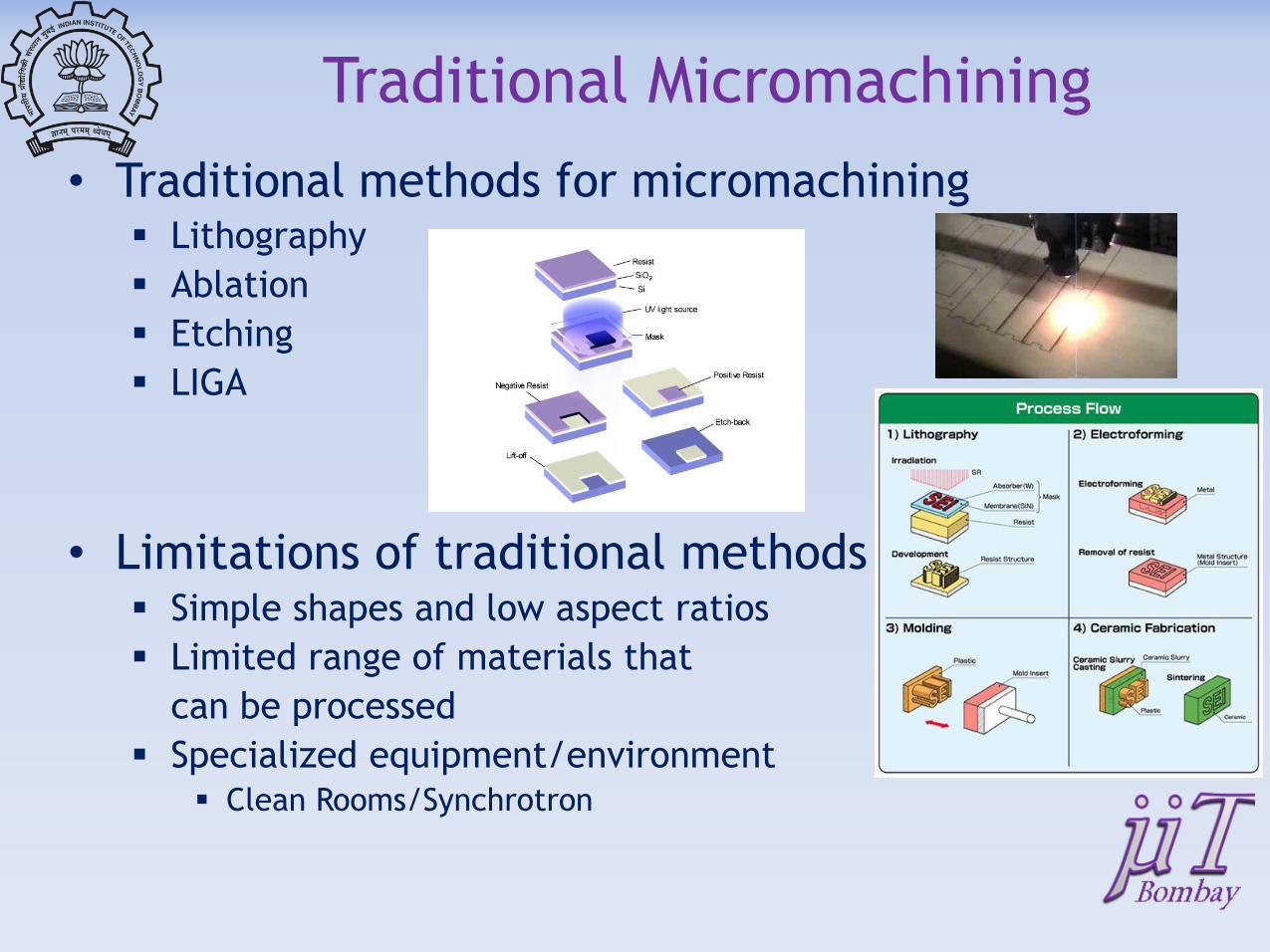
Traditional Micromachining
• Traditional methods for micromachining Lithography
Ablation
Etching
LIGA
• Limitations of traditional methods Simple shapes and low aspect ratios
Limited range of materials that
can be processed
Specialized equipment/environment Clean Rooms/Synchrotron
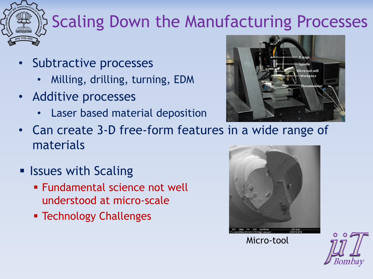
Scaling Down the Manufacturing Processes
• Subtractive processes
• Milling, drilling, turning, EDM
• Additive processes
• Laser based material deposition
• Can create 3-D free-form features in a wide range of
materials
Issues with Scaling
Fundamental science not well
understood at micro-scale
Technology Challenges
Micro-tool
Z stage
Spindle
Micro end mill
Dynamometer
Workpiece
6
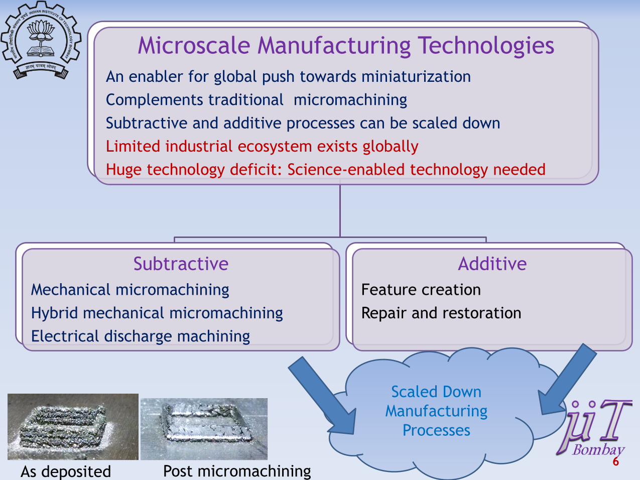
Microscale Manufacturing Technologies
An enabler for global push towards miniaturization
Complements traditional micromachining
Subtractive and additive processes can be scaled down
Limited industrial ecosystem exists globally
Huge technology deficit: Science-enabled technology needed
Subtractive
Mechanical micromachining
Hybrid mechanical micromachining
Electrical discharge machining
Additive
Feature creation
Repair and restoration
Scaled Down
Manufacturing
Processes
As deposited Post micromachining
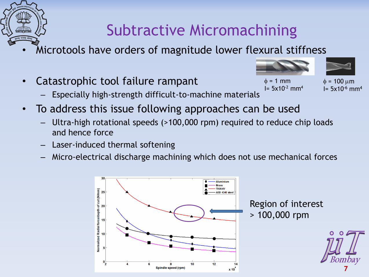
Subtractive Micromachining
• Microtools have orders of magnitude lower flexural stiffness
• Catastrophic tool failure rampant
– Especially high-strength difficult-to-machine materials
• To address this issue following approaches can be used
– Ultra-high rotational speeds (>100,000 rpm) required to reduce chip loads
and hence force
– Laser-induced thermal softening
– Micro-electrical discharge machining which does not use mechanical forces
7
f = 1 mm
I= 5x10⁻² mm4
f = 100 mm
I= 5x10⁻⁶ mm4
Region of interest
> 100,000 rpm
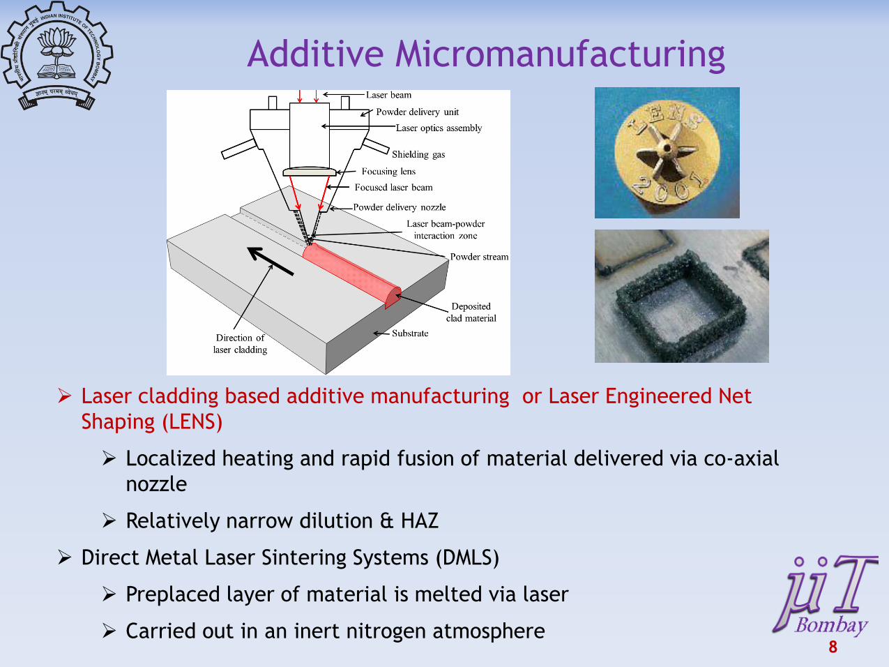
Additive Micromanufacturing
8
Laser cladding based additive manufacturing or Laser Engineered Net
Shaping (LENS)
Localized heating and rapid fusion of material delivered via co-axial
nozzle
Relatively narrow dilution & HAZ
Direct Metal Laser Sintering Systems (DMLS)
Preplaced layer of material is melted via laser
Carried out in an inert nitrogen atmosphere
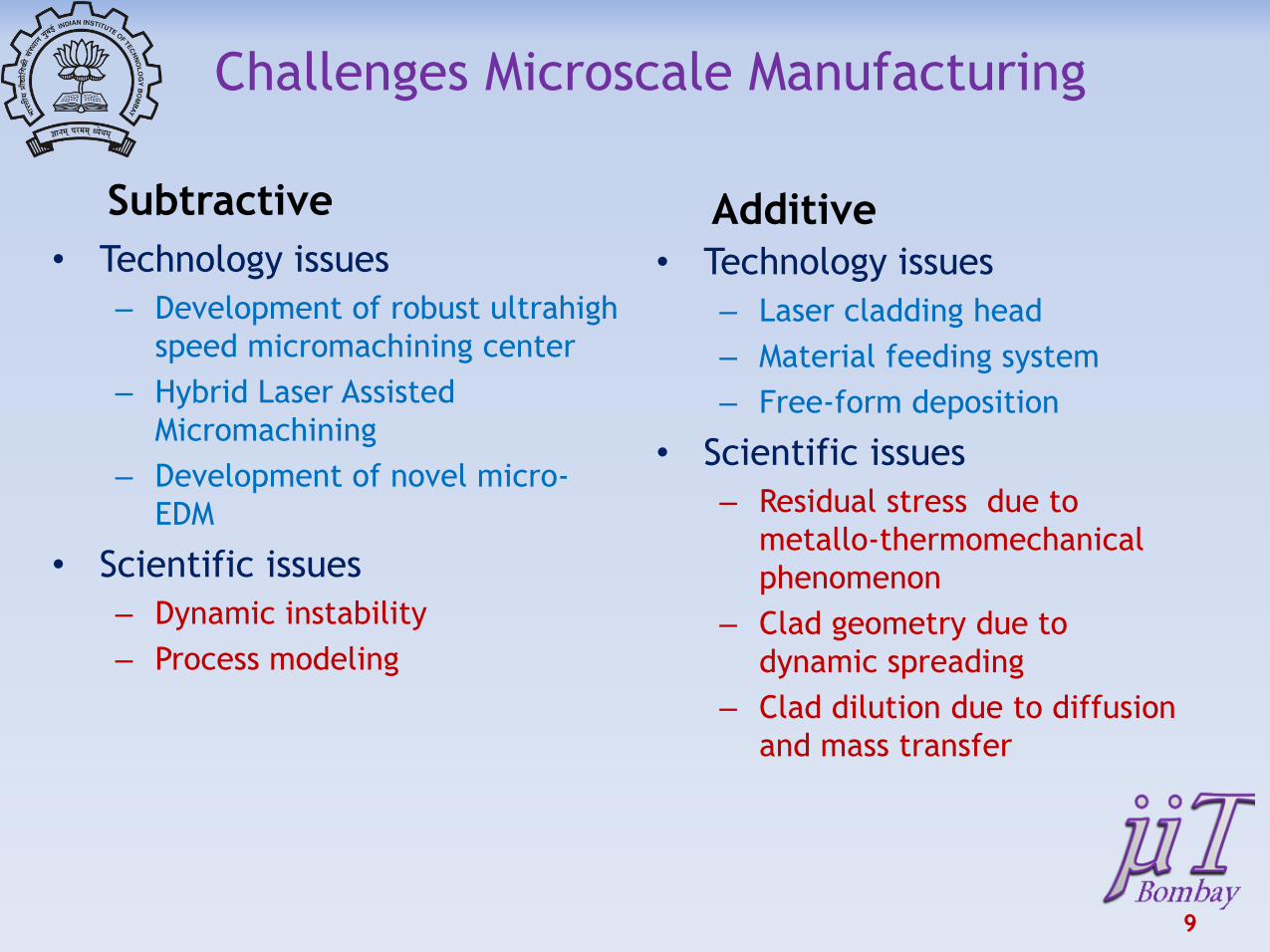
Challenges Microscale Manufacturing
Subtractive
• Technology issues
– Development of robust ultrahigh
speed micromachining center
– Hybrid Laser Assisted
Micromachining
– Development of novel micro-
EDM
• Scientific issues
– Dynamic instability
– Process modeling
Additive
• Technology issues
– Laser cladding head
– Material feeding system
– Free-form deposition
• Scientific issues
– Residual stress due to
metallo-thermomechanical
phenomenon
– Clad geometry due to
dynamic spreading
– Clad dilution due to diffusion
and mass transfer
9

10
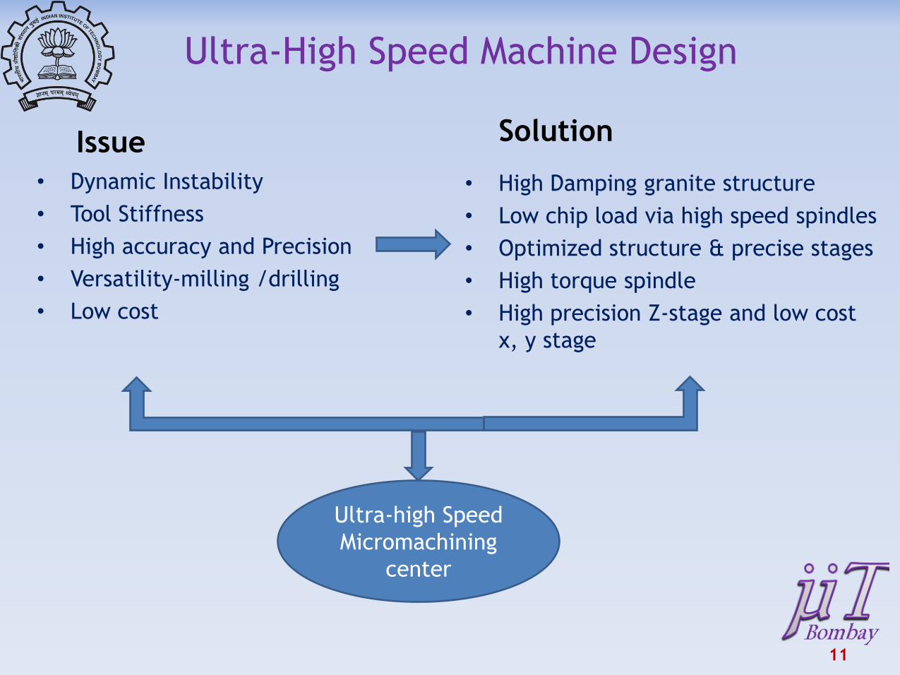
Ultra-High Speed Machine Design
Issue
• Dynamic Instability
• Tool Stiffness
• High accuracy and Precision
• Versatility-milling /drilling
• Low cost
Solution
• High Damping granite structure
• Low chip load via high speed spindles
• Optimized structure & precise stages
• High torque spindle
• High precision Z-stage and low cost
x, y stage
11
Ultra-high Speed
Micromachining
center
12
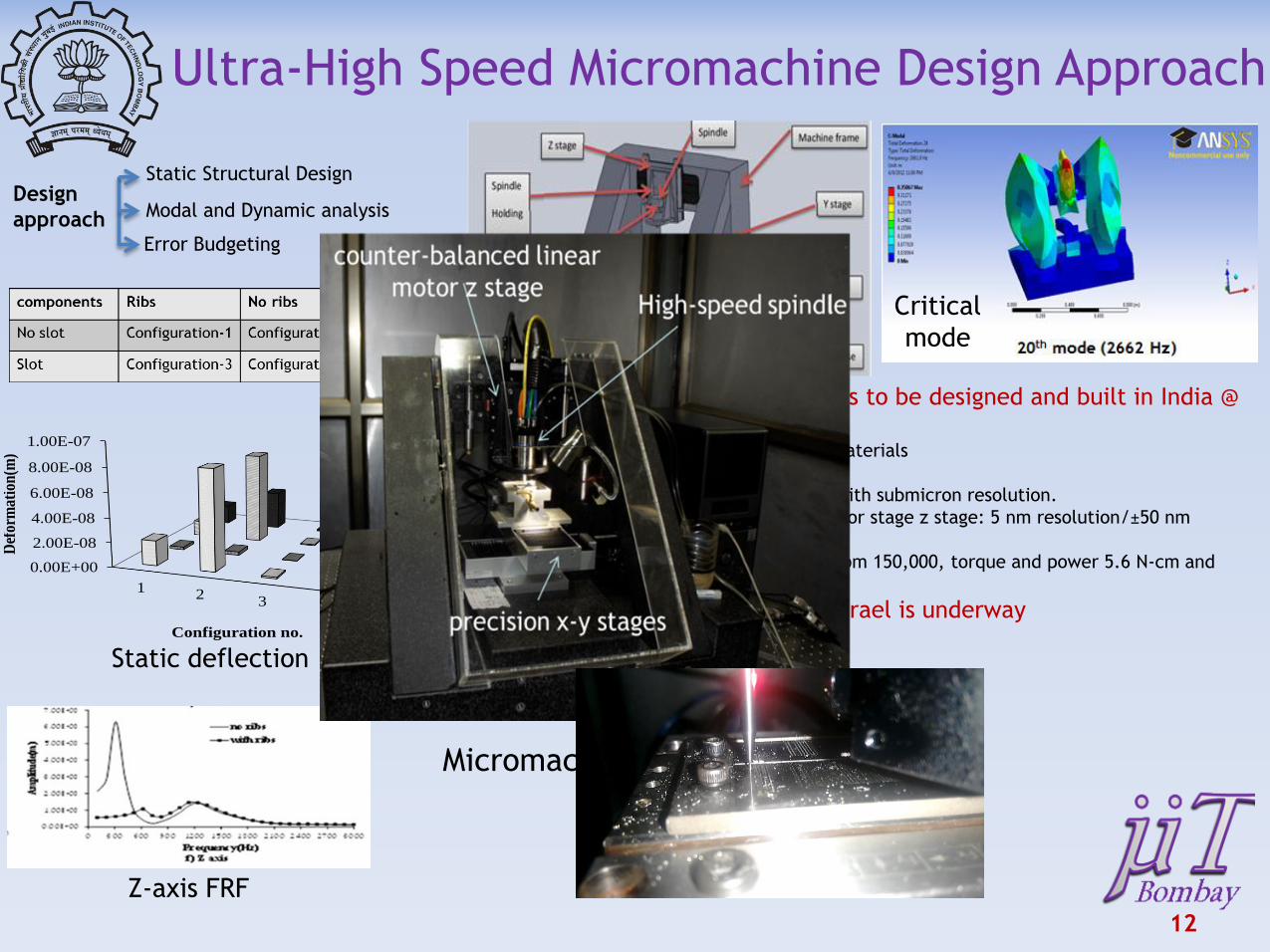
Ultra-High Speed Micromachine Design Approach
0.00E+00
5.00E-07
1.00E-06
1.50E-06
12
3
Def
orm
atio
n(m
)
Model no.
Axial
Radial
0.00E+00
2.00E-08
4.00E-08
6.00E-08
8.00E-08
1.00E-07
12
34
Def
orm
atio
n(m
)
Configuration no.
Max def
def_x
def_y
def_z
(a) Spindle tip deformation (b) Max deformation in machine tool
Design
approach
Static Structural Design
Modal and Dynamic analysis
Error Budgeting
One of the most precise machines to be designed and built in India @
IITB Can create sub-micron features on hard materials
High damping granite structure
X-Y stages with DC brushless servomotor with submicron resolution.
Pneumatically counterbalanced linear motor stage z stage: 5 nm resolution/±50 nm
accuracy
Spindle with ceramic bearing, maximum rpm 150,000, torque and power 5.6 N-cm and
800 W respectively
Commercialization in India and Israel is underway
Micromachining center
Critical
mode
Z-axis FRF
Static deflection
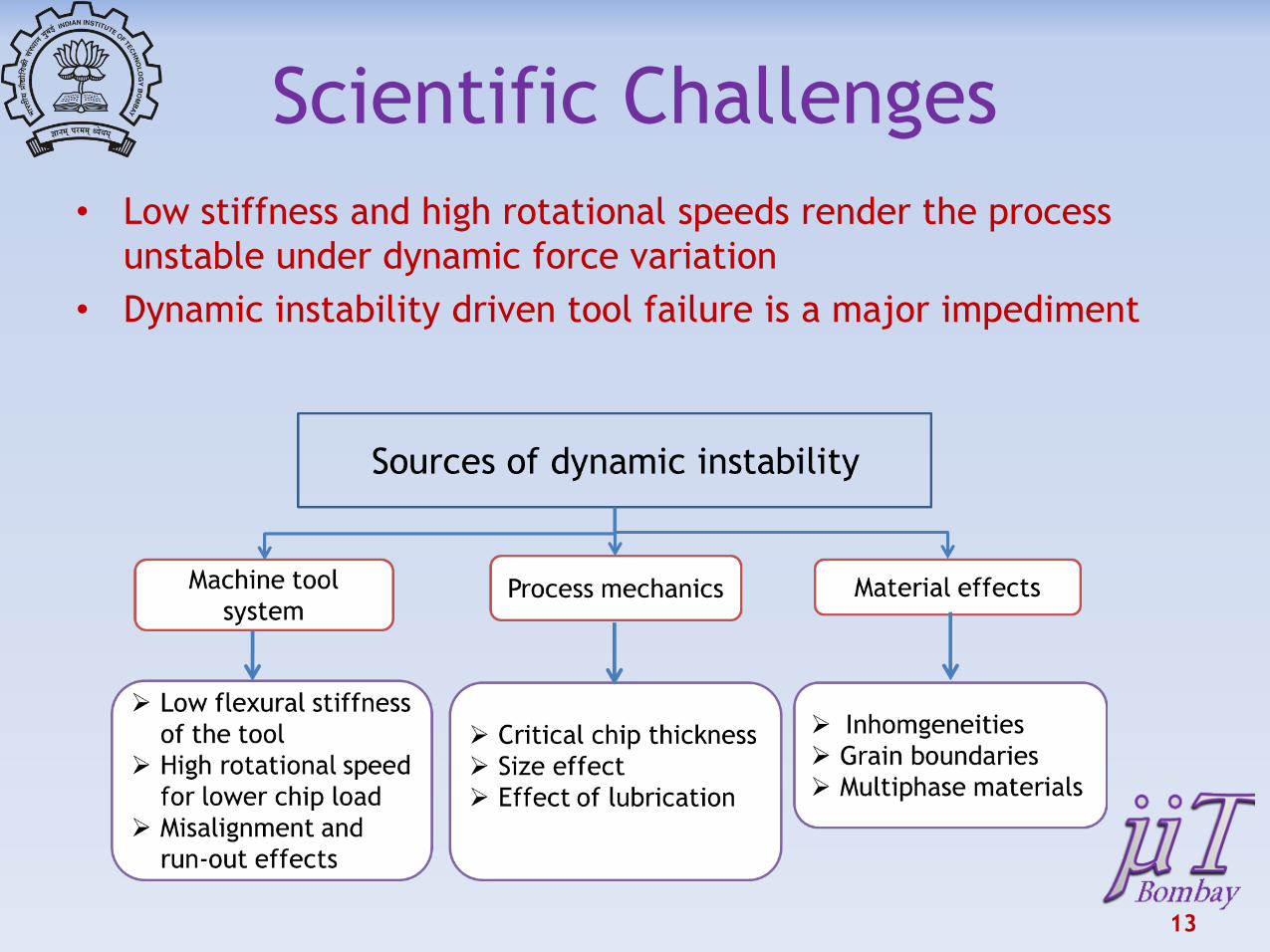
Scientific Challenges
• Low stiffness and high rotational speeds render the process
unstable under dynamic force variation
• Dynamic instability driven tool failure is a major impediment
13
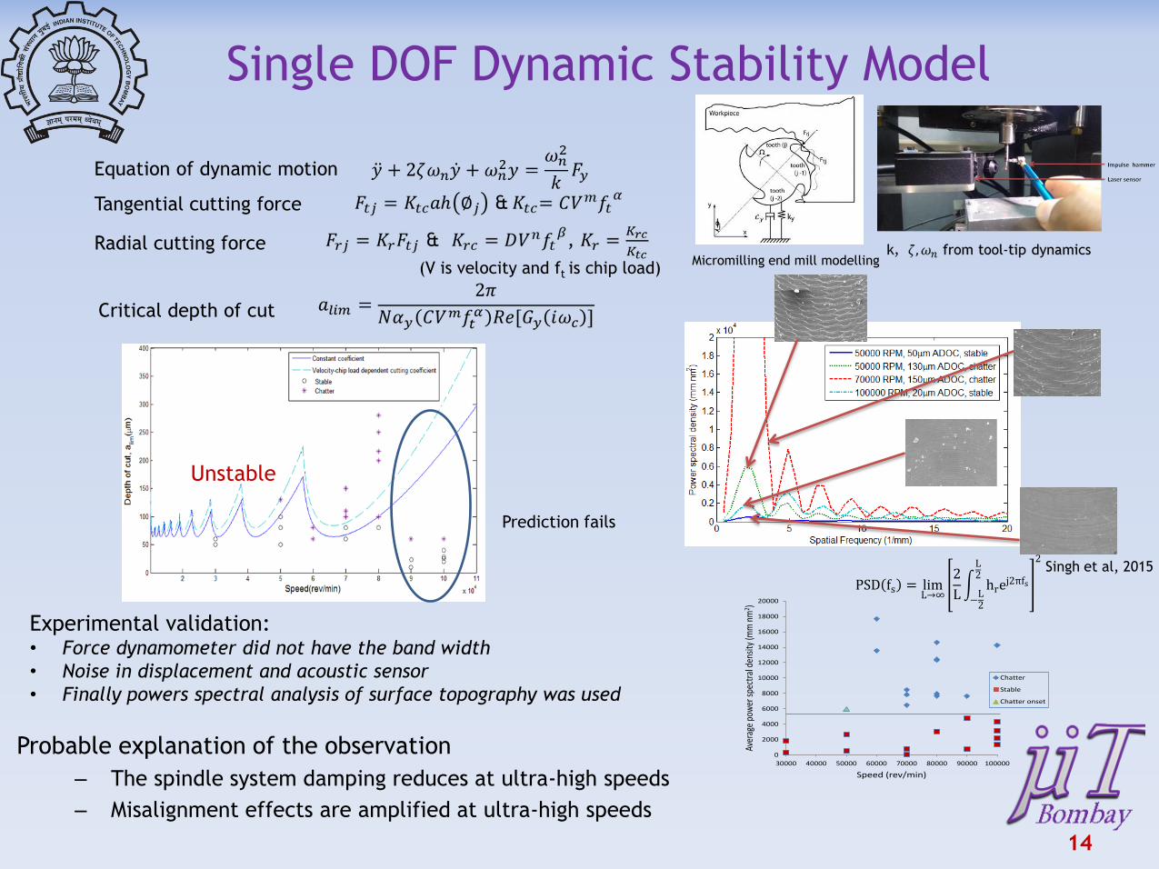
Single DOF Dynamic Stability Model
Equation of dynamic motion
Tangential cutting force
Radial cutting force Micromilling end mill modelling
14
(V is velocity and ft is chip load)
Critical depth of cut
Prediction fails
0
2000
4000
6000
8000
10000
12000
14000
16000
18000
20000
30000 40000 50000 60000 70000 80000 90000 100000
Aver
age
pow
er s
pect
ral d
ensi
ty (m
m n
m2 )
Speed (rev/min)
Chatter
Stable
Chatter onset
Experimental validation: • Force dynamometer did not have the band width
• Noise in displacement and acoustic sensor
• Finally powers spectral analysis of surface topography was used
Singh et al, 2015
Probable explanation of the observation
– The spindle system damping reduces at ultra-high speeds
– Misalignment effects are amplified at ultra-high speeds
Unstable
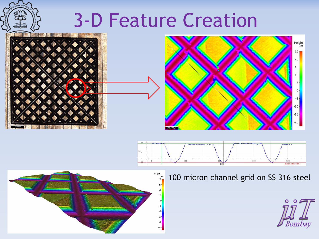
3-D Feature Creation
100 micron channel grid on SS 316 steel
16
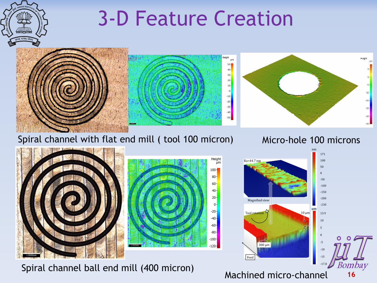
3-D Feature Creation
Spiral channel ball end mill (400 micron)
Spiral channel with flat end mill ( tool 100 micron) Micro-hole 100 microns
Machined micro-channel

17
Laser Assisted Mechanical
Micromachining (LAMM)
• Limitations of mechanical micromachining – Range of materials
– Tool flexural strength/machine-tool system stiffness
– Slow process
• Hybrid laser assisted mechanical micromachining (LAMM) – Integrates thermal softening with mechanical micro-cutting
– Thermal softening of workpiece results in low cutting forces
– Overcomes limitations of machine-tool system stiffness, flexural strength and low MRR
18
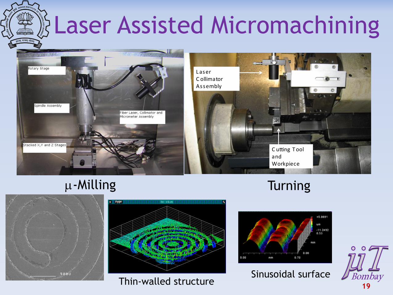
Laser Assisted Micromachining
L aser C ollimator Assembly
C utting T ool and Workpiece
L aser C ollimator Assembly
C utting T ool and Workpiece
m-Milling Turning
19 Thin-walled structure
Sinusoidal surface

20
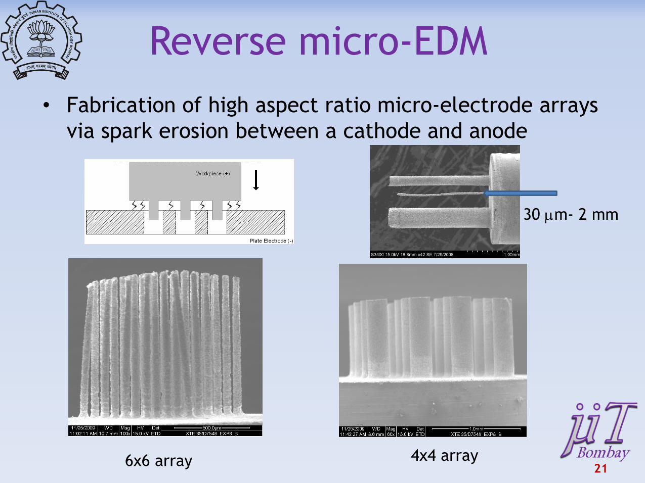
Reverse micro-EDM
• Fabrication of high aspect ratio micro-electrode arrays
via spark erosion between a cathode and anode
21 6x6 array 4x4 array
30 mm- 2 mm
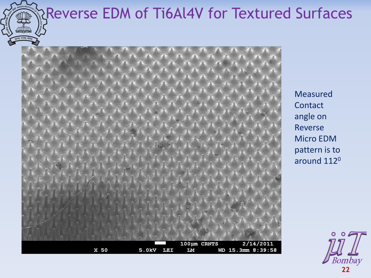
Measured Contact angle on Reverse Micro EDM pattern is to around 1120
Reverse EDM of Ti6Al4V for Textured Surfaces
22

23
24
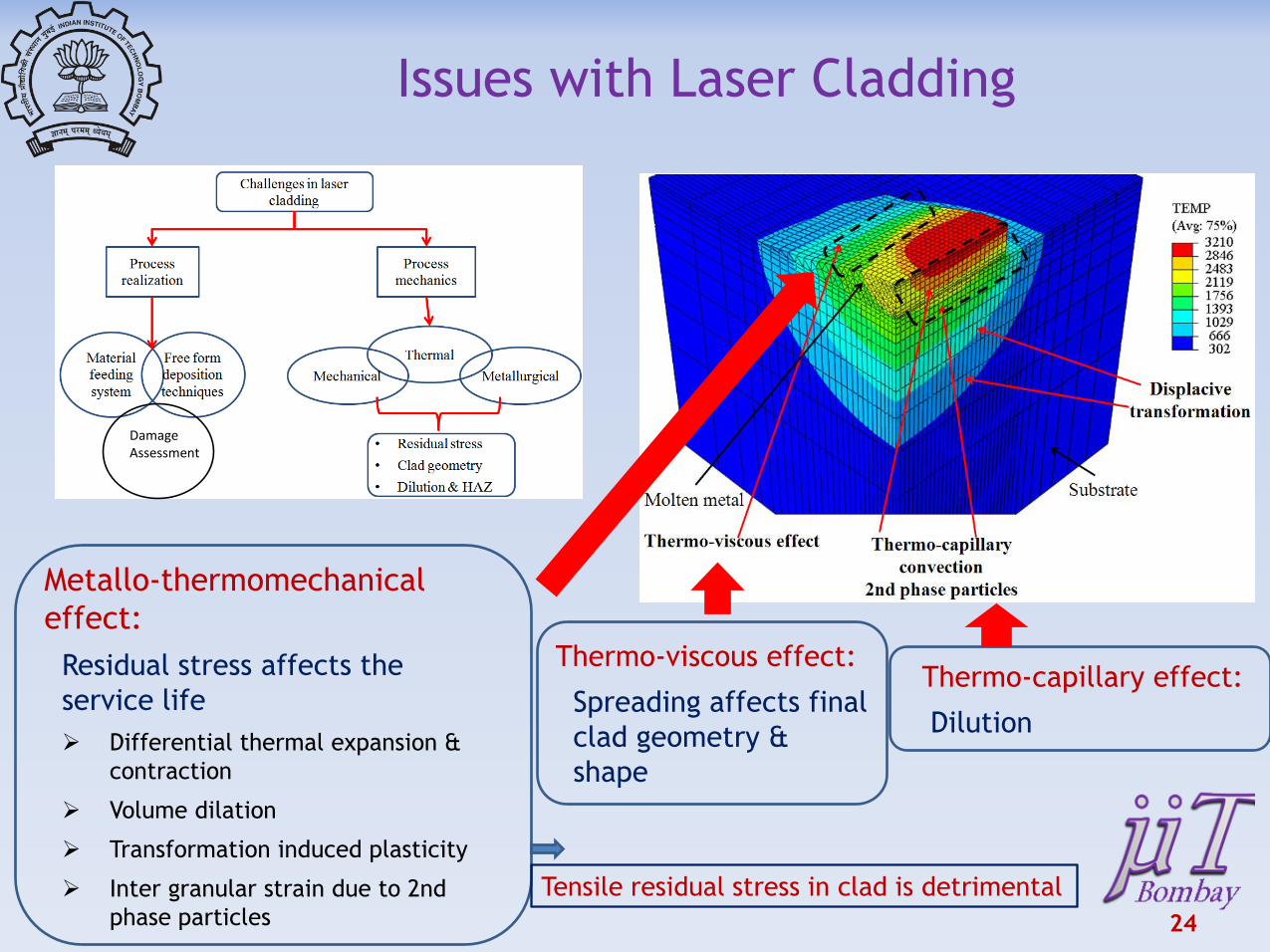
Metallo-thermomechanical
effect:
Residual stress affects the
service life
Differential thermal expansion &
contraction
Volume dilation
Transformation induced plasticity
Inter granular strain due to 2nd
phase particles
Thermo-viscous effect:
Spreading affects final
clad geometry &
shape
Issues with Laser Cladding
Thermo-capillary effect:
Dilution
DamageAssessment
Tensile residual stress in clad is detrimental
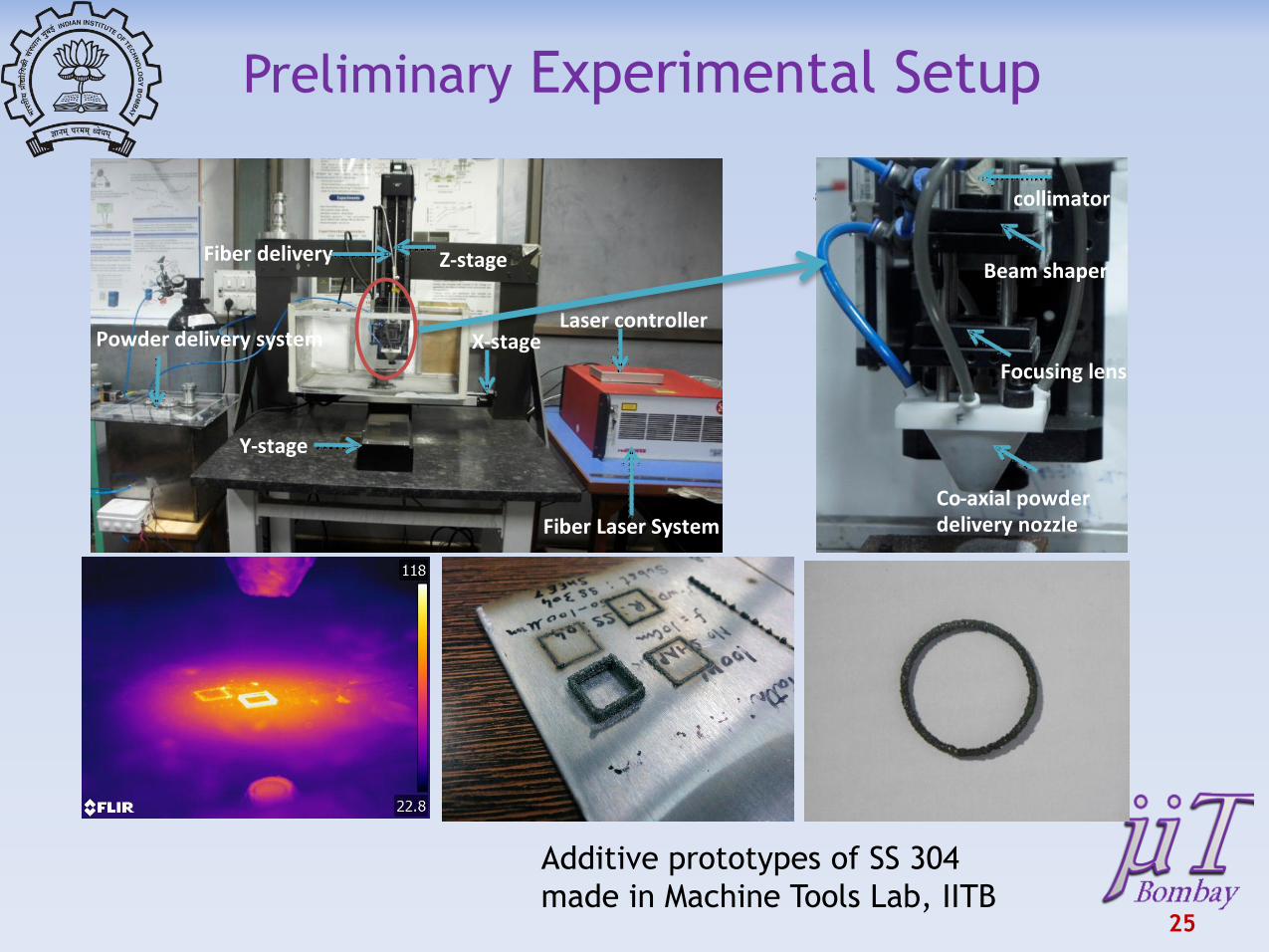
Preliminary Experimental Setup
25
Z-stage
X-stage
Y-stage
Powder delivery systemLaser controller
Fiber Laser System
Fiber delivery
collimator
Beam shaper
Co-axial powder delivery nozzle
Focusing lens
Additive prototypes of SS 304
made in Machine Tools Lab, IITB
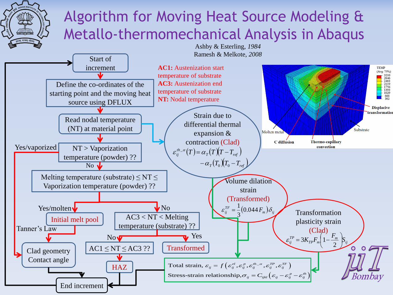
Algorithm for Moving Heat Source Modeling &
Metallo-thermomechanical Analysis in Abaqus
Read nodal temperature
(NT) at material point
Transformed
Initial melt pool
Tanner’s Law
Clad geometry
Contact angle
Start of
increment
Define the co-ordinates of the
starting point and the moving heat
source using DFLUX
AC1 ≤ NT ≤ AC3 ??
AC1: Austenization start
temperature of substrate
AC3: Austenization end
temperature of substrate
NT: Nodal temperature
NT > Vaporization
temperature (powder) ??
Melting temperature (substrate) ≤ NT ≤
Vaporization temperature (powder) ??
Yes/vaporized
No
Yes/molten
AC3 < NT < Melting
temperature (substrate) ??
No
No Yes
HAZ
Strain due to
differential thermal
expansion &
contraction (Clad)
refT
refT
th
ij
TTT
TTTT
00
_
ijm
TF
ij F 044.03
1
Volume dilation
strain
(Transformed)
ijm
mTP
TP
ij SF
FK
213
Transformation
plasticity strain
(Clad)
_Total strain, , , , ,
Stress-strain relationship,
el p th TP TF
ij ij ij ij ij ij
p th
ij ijkl ij ij ij
f
C
Ashby & Esterling, 1984
Ramesh & Melkote, 2008
End increment
Residual Stress Evolution
27
Direction of residual stress measurement
Contour of residual stress along normal direction
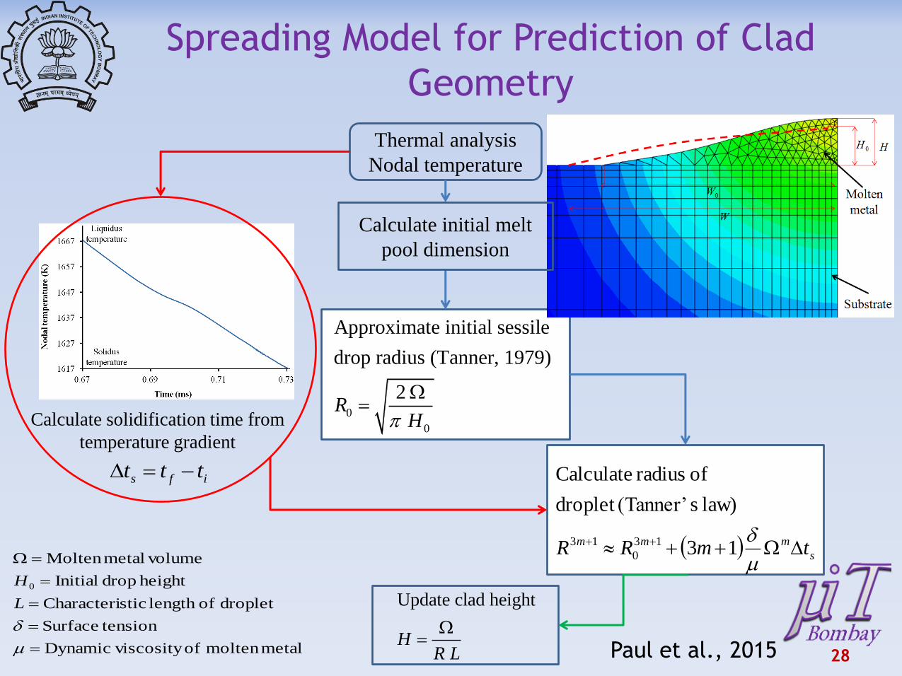
28
Thermal analysis
Nodal temperature
s
mmm tmRR
m
13
law) s(Tanner’droplet
of radius Calculate
13
0
13
ifs ttt
Update clad height
HR L
0
0
Approximate initial sessile
drop radius (Tanner, 1979)
2R
H
metalmolten of viscosityDynamic
tensionSurface
droplet oflength sticCharacteri
height drop Initial
volumemetalMolten
0
m
L
H
Spreading Model for Prediction of Clad
Geometry
Calculate solidification time from
temperature gradient
Calculate initial melt
pool dimension
Paul et al., 2015
Summary & Future Work
29
• Science-enabled technology development for
micromanufacturing
– 5 axis micromachining
– Robotic free-form deposition system
• Commercialization of technologies with existing Industry
linkages
• Creation of a viable micromanufacturing ecosystem in
India to bolster “Make in India” theme
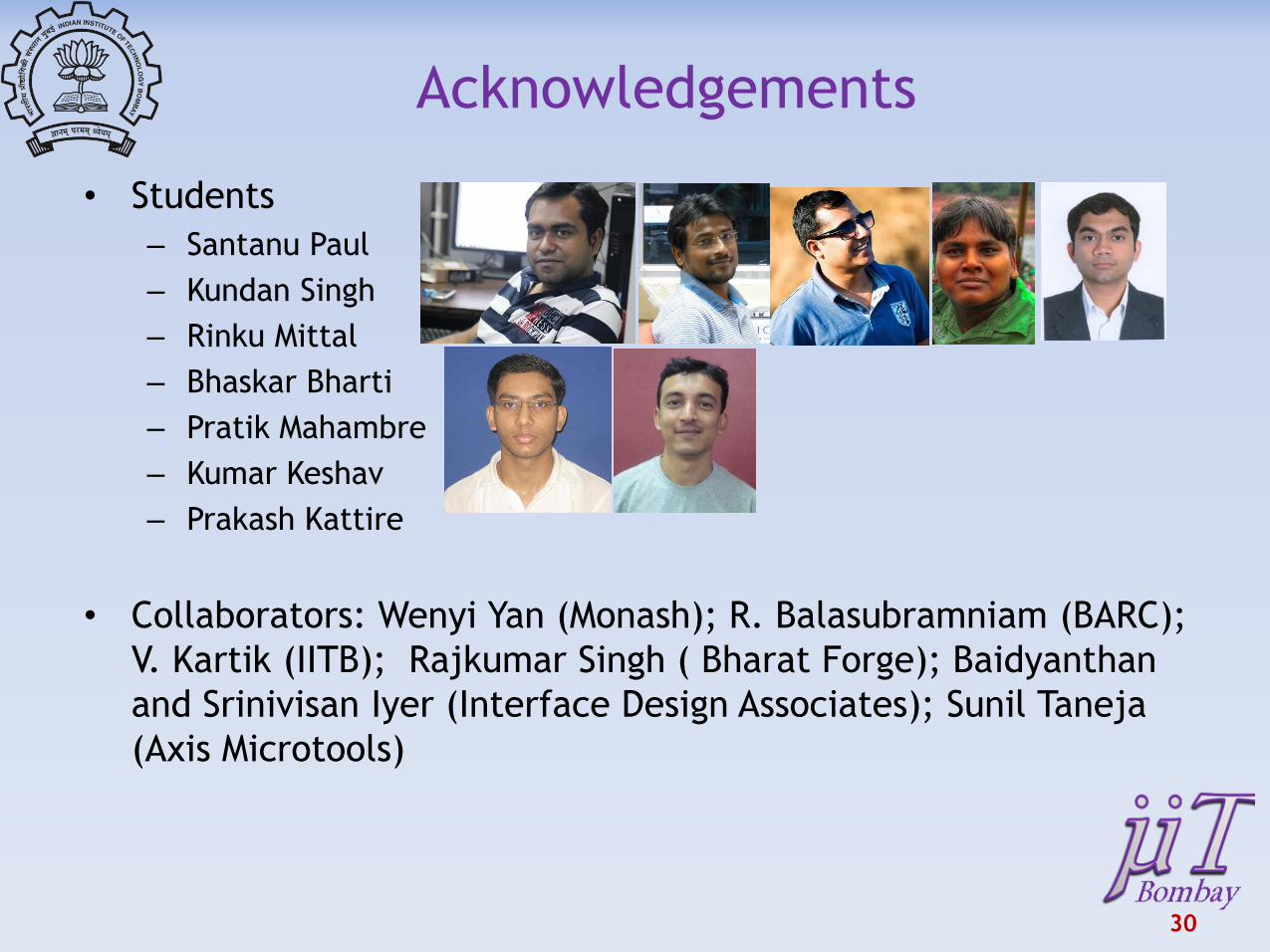
Acknowledgements
• Students
– Santanu Paul
– Kundan Singh
– Rinku Mittal
– Bhaskar Bharti
– Pratik Mahambre
– Kumar Keshav
– Prakash Kattire
• Collaborators: Wenyi Yan (Monash); R. Balasubramniam (BARC);
V. Kartik (IITB); Rajkumar Singh ( Bharat Forge); Baidyanthan
and Srinivisan Iyer (Interface Design Associates); Sunil Taneja
(Axis Microtools)
30
Publications
In Area (2014-2015) 1. Kattire P., Paul S., Singh R., Yan, Wenyi, Singh R. K., “Experimental characterization of laser
cladding of CPM 9V on H13 tool steel for die repair applications” accepted to Journal of Manufacturing Processes
2. Singh, K., Kartik, V. and Singh, R, “Modeling Dynamic Stability in High-speed Micromilling of Ti-6Al-4V via Velocity and Chip Load Dependent Cutting Coefficients” International Journal of Machine Tools and Manufacture, 96(2015), pp. 56–66
3. Gupta, I., Ashraf, K., Paul, S. and Singh, R., "Characterization and Modeling of micro-scale pre-placed powder cladding via fiber laser," ASME Journal of Manufacturing Science and Engineering, 137 (3) (2015), 031019-031032.
4. Singh, K., Singh, R, and Kartik, V. “Comparative Study of Chatter Detection Methods for High-Speed Micromilling of Ti6Al4V,” Procedia Manufacturing (2015) pp. 593-606
5. Paul. S., Ashraf, K., and Singh, R., “Residual Stress Modeling of Powder Injection Laser Surface Cladding for Die Repair Applications,” ASME MSEC Conference, Detroit, 2014
More than 25 publications in micromachining and laser processing Books and Book Chapters
• Singh, R., and Srivastava, A., “Engineering Applications of Lasers,” Manuscript under preparation to be published by CRC press (In progress)
• Singh, R., and Melkote, S. N., “Laser Assisted Mechanical Micromachining,” Smart Devices and Machines for Advanced Manufacturing, co-edited by Dr. Lihui Wang and Dr. Jeff Xi, Springer-Verlag, London, 2008
• Paul S., Singh R., Yan W., “Finite element simulation of laser cladding for tool steel repair”, Lasers based Manufacturing, Springer 2015
31

32
????
![Magneto-DielectricSubstratesinAntenna Miniaturization: … · 2018-09-30 · arXiv:physics/0603116v1 [physics.class-ph] 15 Mar 2006 Magneto-DielectricSubstratesinAntenna Miniaturization:](https://img.pdfslide.us/doc/110x75/5e966d432d89866f0d4e39f6/magneto-dielectricsubstratesinantenna-miniaturization-2018-09-30-arxivphysics0603116v1.jpg)