Embed Size (px)
Citation preview
Chapter 8 – page 1
You need to learn the concepts and formulae highlighted in red. The rest of the text isfor your intellectual enjoyment, but is not a requirement for homework or exams.
Chapter 8SUBTRACTIVE COLOR
MIXING
Subtractive color mixing works for mixingpigments in paints or inks, for color printing,for color photography, and for overlappingmultiple filters in front of projectors.
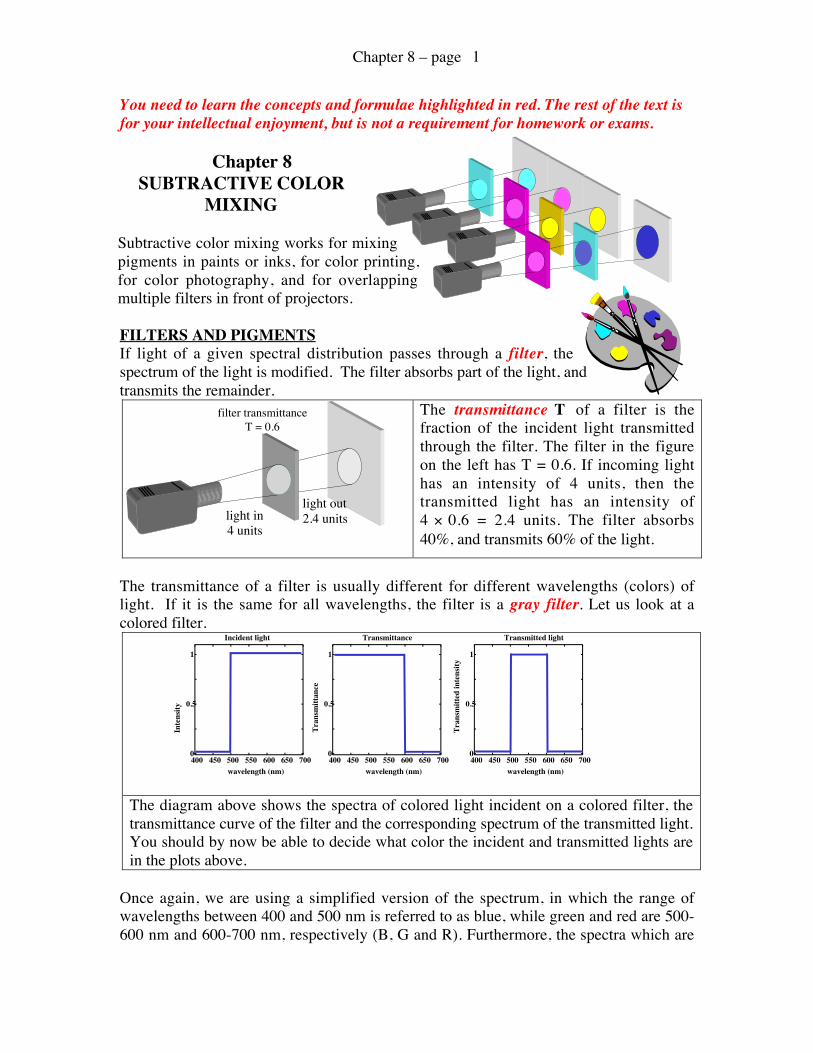
FILTERS AND PIGMENTSIf light of a given spectral distribution passes through a filter, thespectrum of the light is modified. The filter absorbs part of the light, andtransmits the remainder.
The transmittance T of a filter is thefraction of the incident light transmittedthrough the filter. The filter in the figureon the left has T = 0.6. If incoming lighthas an intensity of 4 units, then thetransmitted light has an intensity of4 × 0.6 = 2.4 units. The filter absorbs40%, and transmits 60% of the light.
The transmittance of a filter is usually different for different wavelengths (colors) oflight. If it is the same for all wavelengths, the filter is a gray filter. Let us look at acolored filter.
The diagram above shows the spectra of colored light incident on a colored filter, thetransmittance curve of the filter and the corresponding spectrum of the transmitted light.You should by now be able to decide what color the incident and transmitted lights arein the plots above.
Once again, we are using a simplified version of the spectrum, in which the range ofwavelengths between 400 and 500 nm is referred to as blue, while green and red are 500-600 nm and 600-700 nm, respectively (B, G and R). Furthermore, the spectra which are
filter transmittanceT = 0.6
light in4 units
light out2.4 units
0
0.5
1
400 450 500 550 600 650 700
Incident light
Inte
nsity
wavelength (nm)
0
0.5
1
400 450 500 550 600 650 700
Transmittance
Tran
smitt
ance
wavelength (nm)
0
0.5
1
400 450 500 550 600 650 700
Transmitted light
Tran
smitt
ed in
tens
ity
wavelength (nm)
Chapter 8 – page 2
in reality curved lines, can be simplified as step functions, with vertical and horizontallines, and sharp angles, as in the above figure. This approximation is not always perfectto describe the behavior of light and color, but in most cases it works, and is muchsimpler to use than the real spectral lineshapes. We will later point out cases in which thisapproximation does not apply.
If you were not able to identify the colors in the above spectra, here is a completeexplanation for them. The first spectrum was the incident light. This light had no intensity(I = 0) in the B region, and intensity I = 1 in the G and R regions of the spectrum. This istherefore a mixture of G+R lights. As described in the Chapter 7, G and R lights add toform Y light. The incident light is yellow. The filter, instead, transmits all light in the Band G regions (T = 1), and no light in the R region (T = 0). Since there was no B in theincident light, the only light that the filter can transmit is G. The spectrum of thetransmitted light, therefore, has I = 0 in the B and R regions, and I = 1 in the G region.The filter subtracted red from the incident light. It absorbed the R component from theincident light. We are now beginning to see why this is called subtractive color mixing.
The table below gives the same information contained in the three spectra of the previouspage, in a more schematic way, broken down to the relevant values in each spectralrange:
Simplifiedspectral ranges
Intensity ofincident light
Transmittanceof the filter
Intensity oftransmitted light
B (400-500 nm) 0 1 0G (500-600 nm) 1 1 1R (600-700 nm) 1 0 0
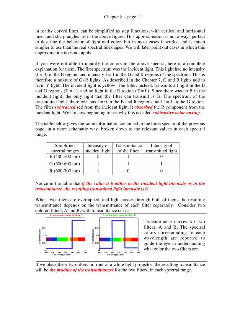
Notice in the table that if the value is 0 either in the incident light intensity or in thetransmittance, the resulting transmitted light intensity is 0.
When two filters are overlapped, and light passes through both of them, the resultingtransmittance depends on the transmittance of each filter separately. Consider twocolored filters, A and B, with transmittance curves:
Transmittance curves for twofilters, A and B. The spectralcolors corresponding to eachwavelength are reported toguide the eye in understandingwhat color the two filters are.
If we place these two filters in front of a white light projector, the resulting transmittancewill be the product of the transmittances for the two filters, in each spectral range.
0
0.25
0.5
0.75
1
400 450 500 550 600 650 700
Transmittance curve for filter A
Tran
smitt
ance
wavelength (nm)
0
0.25
0.5
0.75
1
400 450 500 550 600 650 700
Transmittance curve for filter B
Tran
smitt
ance
wavelength (nm)
Chapter 8 – page 3
The resulting transmittance, TA&B = TA × TB, indicates which colors of light aretransmitted by both filters. It is equivalent to giving the spectrum of the transmitted lightintensity. For the two above filters, we obtain a resulting transmittance of 0 in all threeregions, B, G and R: no light is transmitted by those two filters. Again, schematically weobtained:
Simplifiedspectral ranges
Transmittanceof the filter A
TA
Transmittanceof the filter B
TB
Resultingtransmittance
TA&B = TA × TB
B (400-500 nm) 0 0 0G (500-600 nm) 0 1 0R (600-700 nm) 1 0 0
As you may have observed from the transmittance curves for filters A and B, filter A isred while filter B is green. We saw in Chapters 6 and 7 that when adding lights, R + G =Y. We now observe that when adding the same two colors as subsequent filters, theresulting transmittance is 0 over the whole spectrum, that is, the resulting filter is black:no light can be transmitted by the combination of R and G filters.In other words,
Subtractively, R + G = BlackAdditively, R + G = Yellow.
Subtractive color mixing is very different from additive color mixing!Mixing filters (or pigments, or paints) is very different from mixing lights.
As mentioned, overlapping filters, mixing pigments, or paints, or inks, is calledsubtractive color mixing. The term is a little misleading, because a filter does notsubtract (absorb) a fixed amount of light: it absorbs a fixed fraction of the light incidentupon it. The mathematical operation is not a subtraction. It is rather the multiplication ofthe incident intensity by the transmittance of the filter, or the multiplication of thetransmittances of two filters.
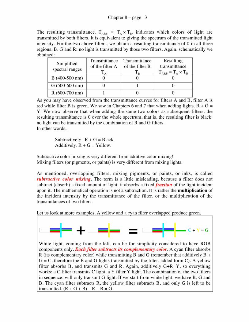
Let us look at more examples. A yellow and a cyan filter overlapped produce green.
White light, coming from the left, can be for simplicity considered to have RGBcomponents only. Each filter subtracts its complementary color. A cyan filter absorbsR (its complementary color) while transmitting B and G (remember that additively B +G = C, therefore the B and G lights transmitted by the filter, added form C). A yellowfilter absorbs B, and transmits G and R. Again, additively G+R=Y, so everythingworks: a C filter transmits C light, a Y filter Y light. The combination of the two filtersin sequence, will only transmit G light. If we start from white light, we have R, G andB. The cyan filter subtracts R, the yellow filter subtracts B, and only G is left to betransmitted. (R + G + B) – R – B = G.
+ = C + Y = G
Chapter 8 – page 4
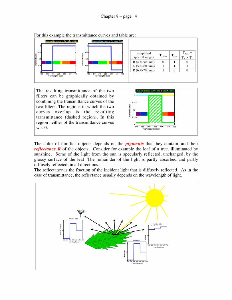
For this example the transmittance curves and table are:
Simplifiedspectral ranges Tyellow Tcyan
TY&C =TY × TC
B (400-500 nm) 0 1 0G (500-600 nm) 1 1 1R (600-700 nm) 1 0 0
The resulting transmittance of the twofilters can be graphically obtained bycombining the transmittance curves of thetwo filters. The regions in which the twocurves overlap is the resultingtransmittance (dashed region). In thisregion neither of the transmittance curveswas 0.
The color of familiar objects depends on the pigments that they contain, and theirreflectance R of the objects. Consider for example the leaf of a tree, illuminated bysunshine. Some of the light from the sun is specularly reflected, unchanged, by theglossy surface of the leaf. The remainder of the light is partly absorbed and partlydiffusely reflected, in all directions.The reflectance is the fraction of the incident light that is diffusely reflected. As in thecase of transmittance, the reflectance usually depends on the wavelength of light.
0
0.25
0.5
0.75
1
400 450 500 550 600 650 700
Transmittance curve for yellow filter
Tran
smitt
ance
wavelength (nm)
0
0.25
0.5
0.75
1
400 450 500 550 600 650 700
Transmittance curve for cyan filter
Tran
smitt
ance
wavelength (nm)
0
0.25
0.5
0.75
1
400 450 500 550 600 650 700Tr
ansm
ittan
cewavelength (nm)
Transmittance curve for Y and C filter
0
0.5
1
400 450 500 550 600 650 700
Reflected light
Ref
lect
ed In
tens
ity
wavelength (nm)0
0.5
1
400 450 500 550 600 650 700
Incident light
Inte
nsity
wavelength (nm)
0
0.5
1
400 450 500 550 600 650 700
Reflectance
Ref
lect
ance
wavelength (nm)
Chapter 8 – page 5
The reflectance indicates the amount oflight diffusely reflected by the leaf in theRGB ranges, separately, as shown in thetable on the right. The reflectancedetermines the color of the leaf, as we seeit.
Simplified spectralranges
Incidentintensity Rleaf
Reflectedlight
B (400-500 nm) 0.8 0 0G (500-600 nm) 0.9 1 0.9R (600-700 nm) 1 0.5 0.5
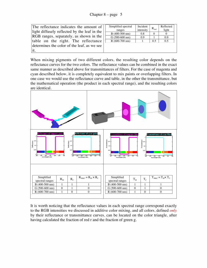
When mixing pigments of two different colors, the resulting color depends on thereflectance curves for the two colors. The reflectance values can be combined in the exactsame manner as described above for transmittances of filters. For the case of magenta andcyan described below, it is completely equivalent to mix paints or overlapping filters. Inone case we would use the reflectance curve and table, in the other the transmittance, butthe mathematical operation (the product in each spectral range), and the resulting colorsare identical.
Simplifiedspectral ranges RM RC
RM&C = RM × RC
B (400-500 nm) 1 1 1G (500-600 nm) 0 1 0R (600-700 nm) 1 0 0
Simplifiedspectral ranges TM TC
TM&C = TM× TC
B (400-500 nm) 1 1 1G (500-600 nm) 0 1 0R (600-700 nm) 1 0 0
It is worth noticing that the reflectance values in each spectral range correspond exactlyto the RGB intensities we discussed in additive color mixing, and all colors, defined onlyby their reflectance or transmittance curves, can be located on the color triangle, afterhaving calculated the fraction of red r and the fraction of green g.
0
0.25
0.5
0.75
1
400 450 500 550 600 650 700
Ref
lect
ance
wavelength (nm)
0
0.25
0.5
0.75
1
400 450 500 550 600 650 700
Ref
lect
ance
wavelength (nm)
Reflectance of cyan paintReflectance of magenta paint
0
0.25
0.5
0.75
1
400 450 500 550 600 650 700
Tran
smitt
ance
wavelength (nm)
0
0.25
0.5
0.75
1
400 450 500 550 600 650 700
Tran
smitt
ance
wavelength (nm)
Transmittance of cyan filterTransmittance of magenta filter
Chapter 8 – page 6
On a computer, magenta and cyan would have the RGB intensities:
M = 255B +0G + 255RandC = 255B + 255G + 0R
Whereas from the reflectance or transmittance curves of the previous page we wouldobtain:
M = 1B +0G + 1RandC = 1B + 1G + 0R
We already discussed the fact that the units and the absolute values of each colorintensity (a, b and c) are not relevant, since the only relevant quantities are the fractionsof red and green.
The fraction of red and green for M and C are:
rM = 0.5 and gM = 0;rC = 0 and gC = 0.5.
Based on these coordinates, it is obvious where M and C are positioned on the colortriangle. When subtractively combining colors of known reflectances, if the resultingreflectance is hard to identify, the fractions of red and green can easily be calculated, andthe color can be identified on the color triangle.
SUBTRACTIVE PRIMARY COLORSThe subtractive primary colors are cyan, magenta and yellow. Each one of these colorsabsorbs one additive primary, its complementary color.
Cyan absorbs red, magenta absorbs green and yellow absorbs blue. All three combined,C, M and Y produce black. Again, these are not the only colors that can be chosen assubtractive primaries. Any other three colors that combined produce black are potentialprimaries, although the mixing potential, that is, the number of colors that can beobtained mixing three primaries is maximum with CMY.
The diagram in the next page shows the absorption of the three subtractive primaries (onthe left) when CMY filters are used. The central part of the diagram shows how to obtainthe additive primaries using combinations of CMY filters. Paints, inks and pigments ingeneral behave just like filter, but in diffusely reflected light, instead of transmitted light.
Chapter 8 – page 7
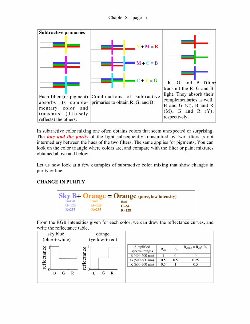
Subtractive primaries
Each filter (or pigment)absorbs its comple-mentary color andtransmits (diffuselyreflects) the others.
Combinations of subtractiveprimaries to obtain R, G, and B.
R, G and B filterstransmit the R, G and Blight. They absorb theircomplementaries as well,B and G (C), B and R(M), G and R (Y),respectively.
In subtractive color mixing one often obtains colors that seem unexpected or surprising.The hue and the purity of the light subsequently transmitted by two filters is notintermediary between the hues of the two filters. The same applies for pigments. You canlook on the color triangle where colors are, and compare with the filter or paint mixturesobtained above and below.
Let us now look at a few examples of subtractive color mixing that show changes inpurity or hue.
CHANGE IN PURITY
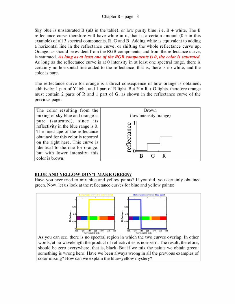
From the RGB intensities given for each color, we can draw the reflectance curves, andwrite the reflectance table. sky blue orange (blue + white) (yellow + red)
Simplifiedspectral ranges RuB RO
RuB&O = RuBx RO
B (400-500 nm) 1 0 0G (500-600 nm) 0.5 0.5 0.25R (600-700 nm) 0.5 1 0.5
Y + M = R
M + C = B
C + Y = G
reflectance
0
1
B G R
reflectance
0
1
B G R
Sky B+ Orange = Orange (pure, low intensity)B=128G=128R=255
B=0G=128R=255
B=0G=64R=128
Chapter 8 – page 8
Sky blue is unsaturated B (uB in the table), or low purity blue, i.e. B + white. The Breflectance curve therefore will have white in it, that is, a certain amount (0.5 in thisexample) of all 3 spectral components, R, G and B. Adding white is equivalent to addinga horizontal line in the reflectance curve, or shifting the whole reflectance curve up.Orange, as should be evident from the RGB components, and from the reflectance curve,is saturated. As long as at least one of the RGB components is 0, the color is saturated.As long as the reflectance curve is at 0 intensity in at least one spectral range, there iscertainly no horizontal line added to the reflectance, that is, there is no white, and thecolor is pure.
The reflectance curve for orange is a direct consequence of how orange is obtained,additively: 1 part of Y light, and 1 part of R light. But Y = R + G lights, therefore orangemust contain 2 parts of R and 1 part of G, as shown in the reflectance curve of theprevious page.
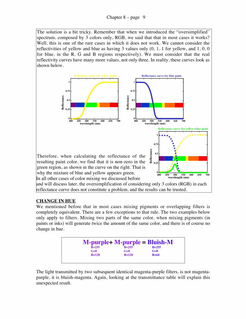
The color resulting from themixing of sky blue and orange ispure (saturated), since itsreflectivity in the blue range is 0.The lineshape of the reflectanceobtained for this color is reportedon the right here. This curve isidentical to the one for orange,but with lower intensity: thiscolor is brown.
Brown(low intensity orange)
BLUE AND YELLOW DON’T MAKE GREEN?Have you ever tried to mix blue and yellow paints? If you did, you certainly obtainedgreen. Now, let us look at the reflectance curves for blue and yellow paints:
0
0.25
0.5
0.75
1
400 450 500 550 600 650 700
Ref
lect
ance
wavelength (nm)
0
0.25
0.5
0.75
1
400 450 500 550 600 650 700
Reflectance curve for blue paint
Ref
lect
ance
wavelength (nm)
Reflectance curve for yellow paint
As you can see, there is no spectral region in which the two curves overlap. In otherwords, at no wavelength the product of reflectivities is non-zero. The result, therefore,should be zero everywhere, that is, black. But if we mix the paints we obtain green:something is wrong here! Have we been always wrong in all the previous examples ofcolor mixing? How can we explain the blue+yellow mystery?
reflectance
0
1
B G R
Chapter 8 – page 9
The solution is a bit tricky. Remember that when we introduced the “oversimplified”spectrum, composed by 3 colors only, RGB, we said that that in most cases it works?Well, this is one of the rare cases in which it does not work. We cannot consider thereflectivities of yellow and blue as having 3 values only (0, 1, 1 for yellow, and 1, 0, 0for blue, in the R, G and B regions respectively). We must consider that the realreflectivity curves have many more values, not only three. In reality, these curves look asshown below.
0
0.25
0.5
0.75
1
400 450 500 550 600 650 700
Ref
lect
ance
wavelength (nm)
0
0.25
0.5
0.75
1
400 450 500 550 600 650 700
Reflectance curve for blue paint
Ref
lect
ance
wavelength (nm)
Reflectance curve for yellow paint
Therefore, when calculating the reflectance of theresulting paint color, we find that it is non-zero in thegreen region, as shown in the curve on the right. That iswhy the mixture of blue and yellow appears green.In all other cases of color mixing we discussed beforeand will discuss later, the oversimplification of considering only 3 colors (RGB) in eachreflectance curve does not constitute a problem, and the results can be trusted.
CHANGE IN HUEWe mentioned before that in most cases mixing pigments or overlapping filters iscompletely equivalent. There are a few exceptions to that rule. The two examples belowonly apply to filters. Mixing two parts of the same color, when mixing pigments (inpaints or inks) will generate twice the amount of the same color, and there is of course nochange in hue.
The light transmitted by two subsequent identical magenta-purple filters, is not magenta-purple, it is bluish-magenta. Again, looking at the transmittance table will explain thisunexpected result.
B=255G=0R=128
B=255G=0R=64
B=255G=0R=128
M-purple+ M-purple = Bluish-M
0
0.25
0.5
0.75
1
400 450 500 550 600 650 700
Ref
lect
ance
wavelength (nm)
Reflectance curve for yellow+blue paint
Chapter 8 – page 10
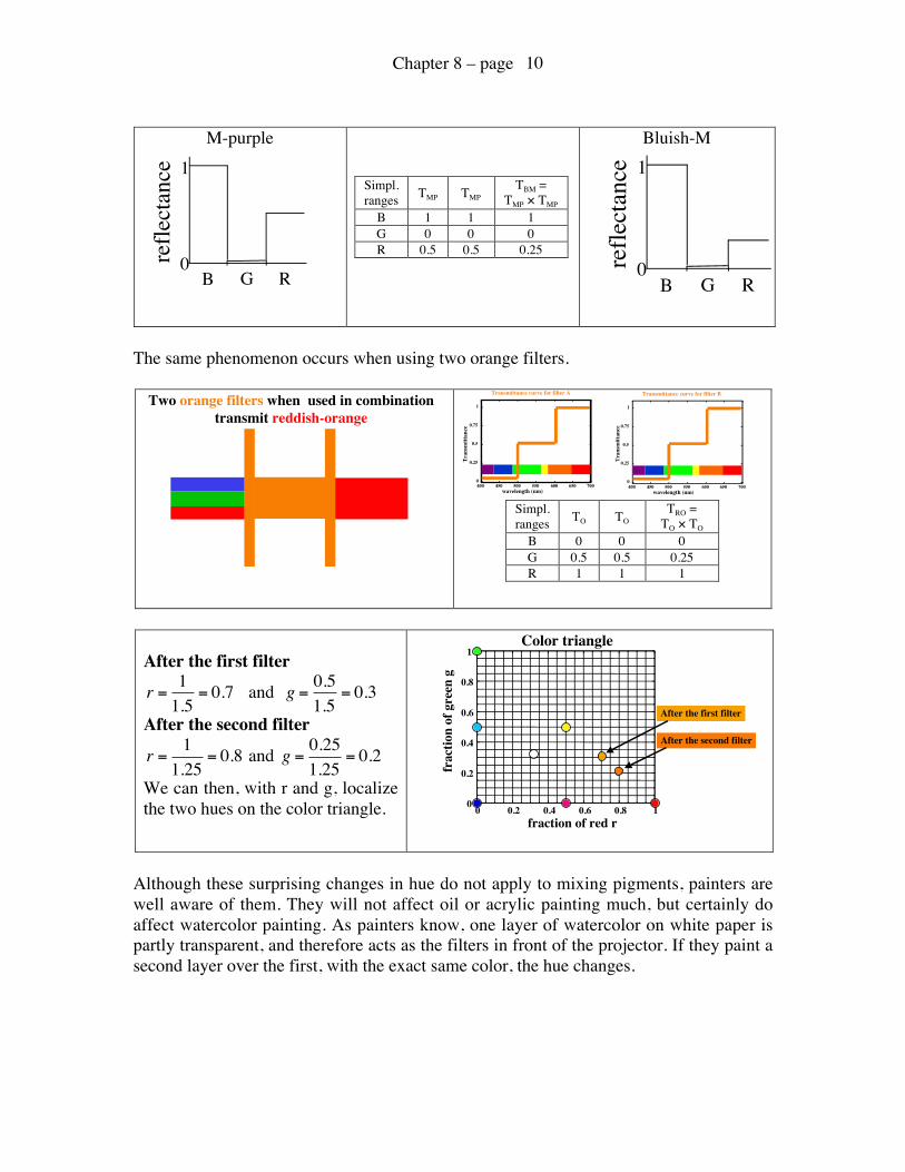
M-purple
Simpl.ranges TMP TMP
TBM =TMP × TMP
B 1 1 1G 0 0 0R 0.5 0.5 0.25
Bluish-M
The same phenomenon occurs when using two orange filters.
Simpl.ranges TO TO
TRO =TO × TO
B 0 0 0G 0.5 0.5 0.25R 1 1 1
After the first filter
€
r =11.5
= 0.7 and
€
g =0.51.5
= 0.3
After the second filter
€
r =11.25
= 0.8 and
€
g =0.251.25
= 0.2
We can then, with r and g, localizethe two hues on the color triangle.
Although these surprising changes in hue do not apply to mixing pigments, painters arewell aware of them. They will not affect oil or acrylic painting much, but certainly doaffect watercolor painting. As painters know, one layer of watercolor on white paper ispartly transparent, and therefore acts as the filters in front of the projector. If they paint asecond layer over the first, with the exact same color, the hue changes.
reflectance
0
1
B G R
reflectance
0
1
B G R
Two orange filters when used in combinationtransmit reddish-orange
0
0.25
0.5
0.75
1
400 450 500 550 600 650 700
Transmittance curve for filter A
Tran
smitt
ance
wavelength (nm)0
0.25
0.5
0.75
1
400 450 500 550 600 650 700
Transmittance curve for filter B
Tran
smitt
ance
wavelength (nm)
fraction of red r
frac
tion
of g
reen
g
Color triangle
0
0.2
0.4
0.6
0.8
1
0 0.2 0.4 0.6 0.8 1
After the first filter
After the second filter
Chapter 8 – page 11
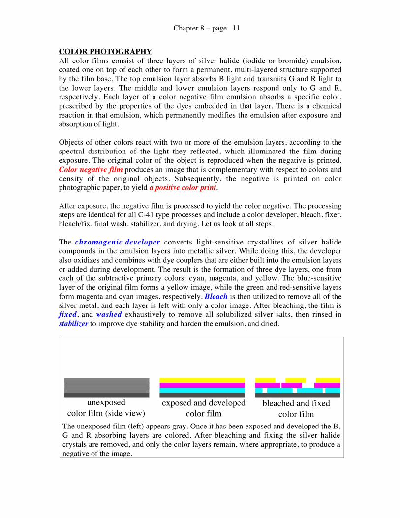
COLOR PHOTOGRAPHYAll color films consist of three layers of silver halide (iodide or bromide) emulsion,coated one on top of each other to form a permanent, multi-layered structure supportedby the film base. The top emulsion layer absorbs B light and transmits G and R light tothe lower layers. The middle and lower emulsion layers respond only to G and R,respectively. Each layer of a color negative film emulsion absorbs a specific color,prescribed by the properties of the dyes embedded in that layer. There is a chemicalreaction in that emulsion, which permanently modifies the emulsion after exposure andabsorption of light.
Objects of other colors react with two or more of the emulsion layers, according to thespectral distribution of the light they reflected, which illuminated the film duringexposure. The original color of the object is reproduced when the negative is printed.Color negative film produces an image that is complementary with respect to colors anddensity of the original objects. Subsequently, the negative is printed on colorphotographic paper, to yield a positive color print.
After exposure, the negative film is processed to yield the color negative. The processingsteps are identical for all C-41 type processes and include a color developer, bleach, fixer,bleach/fix, final wash, stabilizer, and drying. Let us look at all steps.
The chromogenic developer converts light-sensitive crystallites of silver halidecompounds in the emulsion layers into metallic silver. While doing this, the developeralso oxidizes and combines with dye couplers that are either built into the emulsion layersor added during development. The result is the formation of three dye layers, one fromeach of the subtractive primary colors: cyan, magenta, and yellow. The blue-sensitivelayer of the original film forms a yellow image, while the green and red-sensitive layersform magenta and cyan images, respectively. Bleach is then utilized to remove all of thesilver metal, and each layer is left with only a color image. After bleaching, the film isfixed, and washed exhaustively to remove all solubilized silver salts, then rinsed instabilizer to improve dye stability and harden the emulsion, and dried.
The unexposed film (left) appears gray. Once it has been exposed and developed the B,G and R absorbing layers are colored. After bleaching and fixing the silver halidecrystals are removed, and only the color layers remain, where appropriate, to produce anegative of the image.
unexposedcolor film (side view)
exposed and developedcolor film
bleached and fixedcolor film
Chapter 8 – page 12
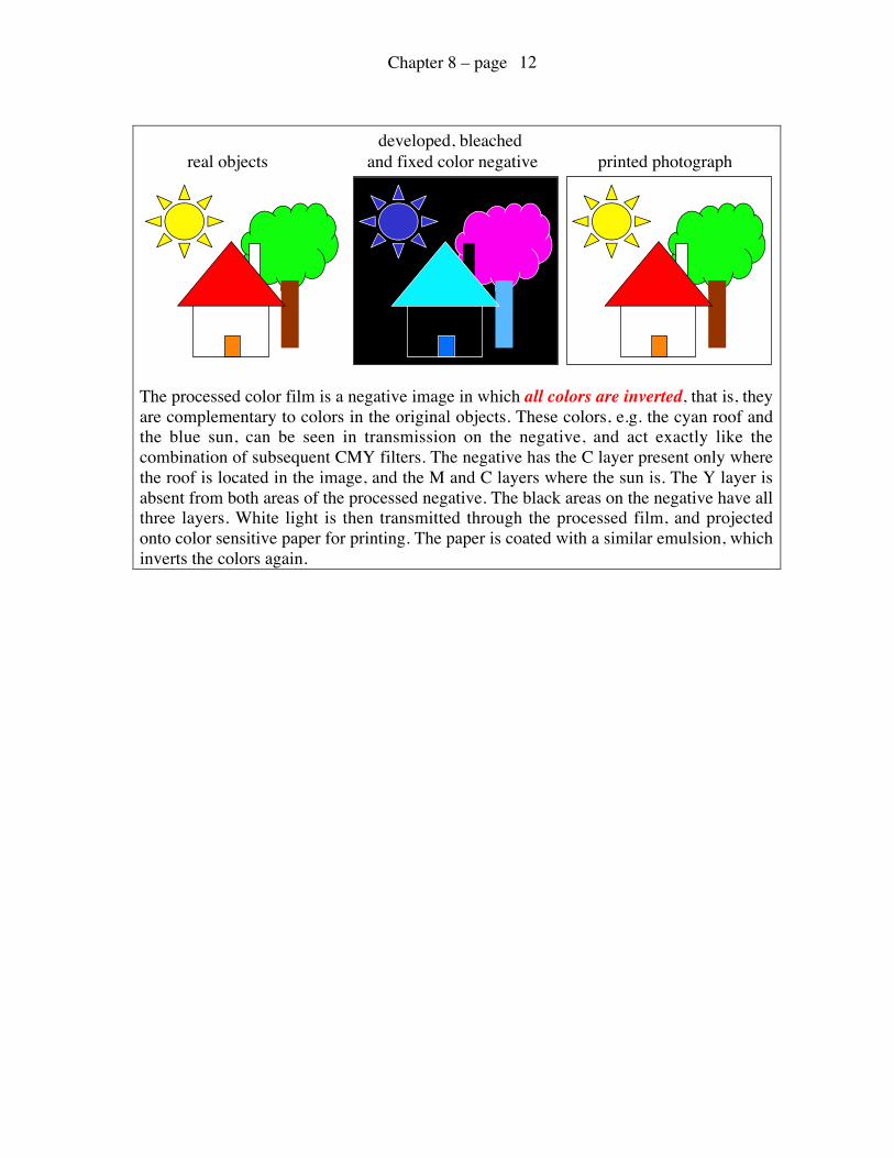
The processed color film is a negative image in which all colors are inverted, that is, theyare complementary to colors in the original objects. These colors, e.g. the cyan roof andthe blue sun, can be seen in transmission on the negative, and act exactly like thecombination of subsequent CMY filters. The negative has the C layer present only wherethe roof is located in the image, and the M and C layers where the sun is. The Y layer isabsent from both areas of the processed negative. The black areas on the negative have allthree layers. White light is then transmitted through the processed film, and projectedonto color sensitive paper for printing. The paper is coated with a similar emulsion, whichinverts the colors again.
real objectsdeveloped, bleached
and fixed color negative printed photograph