Embed Size (px)
Citation preview

An Interaction of Bluetooth Technology for Zero Interaction Authentication
1
School of Computer Science, Carleton University
Honours Project:
An Investigation of
Bluetooth technology for
Zero Interaction Authentication
Jeremy Kong Win Chang
(#:236260)
10 April 2003
Faculty Adviser: Dr. Tony White, Associate Professor, Ph. D, School of
Computer Science, Carleton University
An Interaction of Bluetooth Technology for Zero Interaction Authentication
2
An Investigation of
Bluetooth technology for
Zero Interaction Authentication
Jeremy Kong Win Chang
(#:236260)
Abstract This project is about an investigation surrounding the deployment of
Bluetooth for authentication purposes on network devices. This work defines
Bluetooth, its background and the protocols that Bluetooth technology uses to
perform several operations. We will go deep into the Host Controller Interface of
Bluetooth because it provides a technique that is useful for authentication
purposes.
This project tries to answer the question whether Bluetooth technology
can be useful in the LAN environment. In order to answer that question, the
Bluetooth technology was analyzed to see if it can provide what is needed.
Conclusions and Proposal were suggested as a result of the analysis.
Supervisor: Dr. Tony White

An Interaction of Bluetooth Technology for Zero Interaction Authentication
3
Acknowledgement
I would like first of all to thank my supervisor Dr. Tony White for the
support he has given me throughout this project. I am especially thankful for his
comprehensiveness during the times where the project wasn’t going to well. A
special thought to my parents who constantly supported me despite the long
distance that separates them from me. This project has been a real challenge to
me, discouraging at times nevertheless very interesting. I have found out
throughout the duration of this project that this technology, Bluetooth, is
extremely powerful, i.e. it is meant to substitute any single physical connection
that exists between devices. Having reached the end of this project, I can
definitely say that I was really happy to do this project and that perhaps one day I
will get the change to work on another project or perhaps have a career in
Bluetooth technology.

An Interaction of Bluetooth Technology for Zero Interaction Authentication
4
TABLE OF CONTENTS
1. INTRODUCTION............................................................................................................................... 7 2. BACKGROUND ................................................................................................................................. 8 3. BLUETOOTH..................................................................................................................................... 9
3.1. GENERAL............................................................................................................................................. 9 3.2. POWER REQUIREMENTS..................................................................................................................... 10 3.3. PHYSICAL LINKS................................................................................................................................ 10
3.3.1. Asynchronous Connection-Less Link ........................................................................................ 10 3.3.2. Synchronous Connection-Oriented Link ................................................................................... 11
3.4 LOGICAL CHANNELS .......................................................................................................................... 11 3.5. BLUETOOTH PROTOCOL STACK......................................................................................................... 12 3.6. BLUETOOTH CORE PROTOCOLS ......................................................................................................... 13 3.7. BASEBAND ........................................................................................................................................ 13
3.7.1. Baseband Packets ..................................................................................................................... 14 3.7.2. Access Code .............................................................................................................................. 15 3.7.3. Packet Header........................................................................................................................... 17 3.7.4. Packet Type............................................................................................................................... 20 3.7.5. Payload Format ........................................................................................................................ 23 3.7.6. Bluetooth Connection State....................................................................................................... 25 3.7.7. Bluetooth Addressing ................................................................................................................ 27
3.8. LINK MANAGER PROTOCOL .............................................................................................................. 29 3.9. LOGICAL LINK CONTROL AND ADAPTATION PROTOCOL ................................................................... 30 3.10. SERVICE DISCOVERY PROTOCOL..................................................................................................... 31
4. DESIGN ............................................................................................................................................. 32 4.1 HOST CONTROLLER INTERFACE (HCI) ............................................................................................... 32
4.1.1. USB HCI Architecture .............................................................................................................. 33 4.1.2. HCI Commands......................................................................................................................... 34 4.1.3. HCI Command Packets............................................................................................................. 34 4.1.4. HCI Event Packet...................................................................................................................... 36 4.1.5. HCI Data Packet....................................................................................................................... 37
4.2. OTHER HCI COMMANDS & PARAMETERS......................................................................................... 38 4.3. EVENTS ............................................................................................................................................. 39 4.4. MAIN IMPLEMENTATION PROCESS .................................................................................................... 39 4.5. AUTOMATION PROCESS ..................................................................................................................... 41 4.6. USER-DEFINED APPLICATION............................................................................................................ 42 4.7. SUMMARY ......................................................................................................................................... 42
5. DISCUSSION.................................................................................................................................... 45 6. CONCLUSIONS AND PROPOSAL FOR FUTURE WORK............................................................ 49 7. REFERENCES ....................................................................................................................................... 51 APPENDIX 1 .............................................................................................................................................. 52 APPENDIX 2 .............................................................................................................................................. 53 APPENDIX 3 .............................................................................................................................................. 55 APPENDIX 4 .............................................................................................................................................. 56 APPENDIX 5 .............................................................................................................................................. 57 APPENDIX 6 .............................................................................................................................................. 58 APPENDIX 7 .............................................................................................................................................. 59

An Interaction of Bluetooth Technology for Zero Interaction Authentication
5
APPENDIX 8 .............................................................................................................................................. 60 APPENDIX 9 .............................................................................................................................................. 62 APPENDIX 10 ............................................................................................................................................ 63 APPENDIX 11 ............................................................................................................................................ 66 APPENDIX 12 ............................................................................................................................................ 67 APPENDIX 13 ............................................................................................................................................ 73 APPENDIX 14 ............................................................................................................................................ 74 APPENDIX 15 ............................................................................................................................................ 75 APPENDIX 16 ............................................................................................................................................ 76 APPENDIX 17 ............................................................................................................................................ 79
List of Figures Figure 1: Functional blocks in Bluetooth System .................................................................................... 9 Figure 2: The Bluetooth Protocol Stack.................................................................................................. 13 Figure 3: Piconet with multi slave operations and a scatternet........................................................... 14 Figure 4: Packet Format ........................................................................................................................... 14 Figure 5: Access Code format ................................................................................................................. 15 Figure 6: Preamble .................................................................................................................................... 15 Figure 7: Trailer in CAC when MSB of sync word is 0 (a) and 1(b) ................................................... 16 Figure 8: Header format............................................................................................................................ 17 Figure 9: FHS packet payload format ..................................................................................................... 22 Figure 10: 1-byte payload header ........................................................................................................... 24 Figure 11: 2-bytes payload header ......................................................................................................... 24 Figure 12: CRC generation and checking .............................................................................................. 25 Figure 13: Format of BD_ADDR.............................................................................................................. 28 Figure 14: Link Manager........................................................................................................................... 30 Figure 15: L2CAP with protocol layers ................................................................................................... 30 Figure 16: SDP configuration ................................................................................................................... 31 Figure 17: Bluetooth Hardware Architecture ......................................................................................... 32 Figure 18: Bluetooth block diagram with USB HCI ............................................................................... 33 Figure 19: Bluetooth block diagram with PC-Card HCI........................................................................ 34 Figure 20: HCI Command Packet ........................................................................................................... 36 Figure 21: HCI Event Packet.................................................................................................................... 37 Figure 22: HCI ACL Data Packet ............................................................................................................ 37 Figure 23: HCI SCO Data Packet............................................................................................................ 37 Figure 24: MSC of Device Inquiry ........................................................................................................... 40 Figure 25: Use Case diagram of system ................................................................................................ 43 Figure 26: State Machine ......................................................................................................................... 44 Figure 27: Snapshot of HCI Commands ................................................................................................ 50
List of Tables Table 1: Bluetooth Protocol Layer ........................................................................................................... 12 Table 2: Access Code types .................................................................................................................... 17 Table 3: Packets defined for SCO and ACL link pages ....................................................................... 53 Table 4: Description of FHS packet payload ......................................................................................... 54 Table 5: Contents of SR field ................................................................................................................... 54 Table 6: Contents of SP field ................................................................................................................... 54

An Interaction of Bluetooth Technology for Zero Interaction Authentication
6
Table 7: Contents of page scan mode field ........................................................................................... 55 Table 8: Link Control Packets .................................................................................................................. 55 Table 9: ACL packets ................................................................................................................................ 56 Table 10: SCO packets............................................................................................................................. 56 Table 11: Logical channel L_CH field contents ..................................................................................... 56 Table 12: CID Definitions.......................................................................................................................... 57 Table 13: Command Packet Op_Code................................................................................................... 58 Table 14: Command Packet Parameter_Total _Length....................................................................... 58 Table 15: Command Packet Parameter ................................................................................................. 59 Table 16: Event Packet Op_Code........................................................................................................... 59 Table 17: Event Packet Parameter_Total_Length................................................................................ 59 Table 18: Event Packet Parameter ......................................................................................................... 60 Table 19: HCI ACL Data packet Connection_Handle .......................................................................... 60 Table 20: HCI ACL Data packet Packet_Boundary_Flag .................................................................... 61 Table 21: HCI ACL Data packet Broadcast_Flag ................................................................................. 61 Table 22: HCI ACL Data packet data_Total_Length ............................................................................ 61 Table 23: HCI SCO Data packet Connection_Handle ......................................................................... 62 Table 24: HCI SCO Data packet Reserved ........................................................................................... 63 Table 25: HCI SCO Data packet Data_Total_Length .......................................................................... 63 Table 26: Link Control Commands.......................................................................................................... 65 Table 27: Link Policy Commands............................................................................................................ 66 Table 28: Host Controller & Baseband Commands.............................................................................. 72 Table 29: Informational Parameters........................................................................................................ 73 Table 30: Status Parameters ................................................................................................................... 74 Table 31: Testing Commands.................................................................................................................. 75 Table 32: Event .......................................................................................................................................... 78 Table 33: Acronyms and Abbreviations.................................................................................................. 79

An Interaction of Bluetooth Technology for Zero Interaction Authentication
7
1. Introduction
Bluetooth is a global standard for wireless connectivity. It is a worldwide
specification for a low cost, low power, short-range radio technique introduced by
Ericsson and others. Bluetooth technology facilitates the replacement of the
cables normally used to connect one device to another, with one universal short-
range radio link.
The goal of eliminating cables has lead to the creation of the notion of
Personal Area Networks (PAN), a close range network surrounding a person
carrying several heterogeneous devices equipped with wireless communication
techniques. Two Bluetooth devices can talk to each other when they come within
a range of 10 meters to each other. Due to their dependence on a radio link, as
opposed to alternate technology such as an infrared connection, Bluetooth
devices do not require a line-of-sight connection in order to communicate. For
example, a laptop could print information on a printer in the adjoining.
Using the properties of Bluetooth technology, I will investigate how
connectivity can be established between two devices, a Bluetooth-enabled PDA
(Personal Digital Assistant) and similarly-equipped laptop (or desktop), such that
the laptop (or desktop) will automatically load the user configurations (like a
normal login) upon connection. Similarly, when connectivity is broken (“the user
goes away”), a user-defined application is run automatically.

An Interaction of Bluetooth Technology for Zero Interaction Authentication
8
2. Background
The code name Bluetooth was taken from the name of the tenth-century
Danish King Harald Gormsson, nickname Danish King Harald Bluetooth.
Nowadays Bluetooth represents an alliance between mobile communications and
mobile computing companies, as well as a standard for short-range wireless
communications. During 1998, a group of computer and telecommunications
companies began to investigate methods to quickly and easily connect different
types of mobile devices known mobile phone manufacturers as Ericsson and
Nokia, as well as laptop manufacturers IBM and Toshiba and the chip
manufacturer Intel. This initial core group of companies formed a special interest
group (SIG) on May 20, 1998 to design a royalty-free, open specification
technology that was assigned the code name Bluetooth.

An Interaction of Bluetooth Technology for Zero Interaction Authentication
9
3. Bluetooth
3.1. General
Bluetooth technology achieves its goal by embedding small, inexpensive,
short-ranged, radio transceivers into the devices that are available today, either
directly or through an adapter such as a PC card. Bluetooth devices operate at
2.4 GHz in the license free Industrial Scientific and Medical (ISM) band. This
band specifies a basic set of power, spectral emission and interference rules.
The ISM band ranging from 2.4465 to 2.4835 GHz is divided into twenty-three 1
MHz channels, each signaling data at a maximum of 1 Mega-symbol per second.
Bluetooth sends one packet in one of these 1 MHz slots and then both the
receiver and the sender tunes into another channel. This results in a hopping
process that eventually will make sure that all the 79 or 23 RF channels will be
used. This behaviour is called FHSS – Frequency Hopping Spread Spectrum.
Under the frequency-hopping scheme employed by Bluetooth, the 1600 hops per
second translate into duration of 625 milliseconds per hops. Frequency hopping
is employed to reduce the effect from signal interference and fading, with the
expected range of a typical Bluetooth device being approximately 10 or 100m
and the actual range (10 or 100m) depending on the power level. The Bluetooth
System consists of a radio unit, a link control unit, and a support unit for link
management and host terminal interface functions
Figure 1: Functional blocks in Bluetooth System

An Interaction of Bluetooth Technology for Zero Interaction Authentication
10
3.2. Power Requirements
With a relatively restricted wireless transmission distance, you would
expect a Bluetooth-compatible device to have a low power requirement. In
recognition that different devices support different types of data transfer comes
the recognition that different devices also have different power requirements. The
three different power modes are; 1mW (0dBm) which is the standard level,
2.5mW (+4dBm) and 100mW (+20dBm). These will give the device an
operational range of 10, 20 or 100 m respectively.
3.3. Physical Links
Bluetooth supports two kinds of links:
• Asynchronous Connection-Less (ACL).
• Synchronous Connection-Oriented (SCO).
Bluetooth supports one ACL channel, three SCO channels or one channel
that simultaneously supports asynchronous data and synchronous voice.
3.3.1. Asynchronous Connection-Less Link
The ACL link is a point-to-multipoint link between the master and all the
slaves. In the slots not reserved for SCO links, the master can exchange packets
with any slave on a per-slot basis. Between a master and a slave only a single
ACL link can exist. A slave is permitted to return an ACL packet in the slave-to-
master slot if and only if it has been addressed in the preceding master-to-slave
slot. If the slave fails to decode the slave address in the packet header, it is not
allowed to transmit. This assures data integrity. ACL packets not addressed to a
specific slave are considered as broadcast packets and are read by every slave.

An Interaction of Bluetooth Technology for Zero Interaction Authentication
11
If there is no data to be sent on the ACL link and no polling is required, no
transmission shall take place.
3.3.2. Synchronous Connection-Oriented Link
The SCO link is a symmetric, point-to-point link between the master and a
specific slave. The SCO link reserves slots and can therefore be considered as a
circuit-switched connection between the master and the slave. The SCO link
typically supports time-bounded information like voice. The master can support
up to three SCO links to the same slave or to different slaves. A slave can
support up to three SCO links from the same master or two SCO links if the links
originate from different masters. SCO packets are never retransmitted.
3.4 Logical Channels Five logical channels are defined in the Bluetooth system:
• LC control channel
• LM control channel
• UA user channel
• UI user channel
• US user channel
The control channel LC and LM are used at the link control level and link
manager level, respectively. The user channels UA, UI, and US are used to carry
asynchronous, isochronous and synchronous user information, respectively. The
LC channel is carried in the packet header; all other channels are carried in the
packet payload. The LM, UA and UI channels are indicated in the L_CH field in
the packet header. The US channel is carried by the SCO link only; the UA and
UI channels are normally carried by the ACL link; however, they can also be

An Interaction of Bluetooth Technology for Zero Interaction Authentication
12
carried by the data in the DV packet on the SCO link. The LM channel can be
carried either by the SCO or the ACL link.
3.5. Bluetooth Protocol Stack
Similar to other modern communications technologies, Bluetooth includes
a protocol stack within its specification. The protocol stack which is illustrated in
Figure 4.4 (a) does not represent a conventional protocol stack similar to the
seven-layer International Standards Organization (ISO) Open System
Interconnection (OSI) reference model. Because Bluetooth uses RF
communications and interoperates with telephones and other devices, it is a bit
difficult to categorize its protocol stack in a manner similar to the seven-layer OSI
reference model. Instead of following the seven-layer ISO reference model, the
Bluetooth specification divides its protocol stack into four layers accordingly to
the purpose of the protocol.
Protocol Layer Protocols
Bluetooth Core Protocols Baseband, LMP, L2CAP, SDP
Cable Replacement Protocol RFCOMM
Telephony Control Protocols TCS Binary
Adopted Protocols OBEX
Table 1: Bluetooth Protocol Layer

An Interaction of Bluetooth Technology for Zero Interaction Authentication
13
Figure 2: The Bluetooth Protocol Stack
3.6. Bluetooth Core Protocols
Bluetooth consists of four core protocols:
• Baseband
• Link Manager Protocol (LMP)
• Logical Link Control and Adaptation Protocol (L2CAP)
• Service Discovery Protocol (SDP)
3.7. Baseband
The Baseband and Link Protocol enable the physical RF connection
between devices. The connection of two to seven active Bluetooth devices forms
a small network referred to as a piconet. In addition many more devices can be
Object Exchange Protocol (OBEX)
Telephony Control Protocol
(TCS)
RFCOMM Service Discovery
Protocol (SDP)
Audio
Logical Link Control and Adaptation Protocol (L2CAP)
Voice
Link Manager Protocol (LMP)Host Controller Interface
Baseband-Link Controller (LC) ACL SCO
Bluetooth Radio
An Interaction of Bluetooth Technology for Zero Interaction Authentication
14
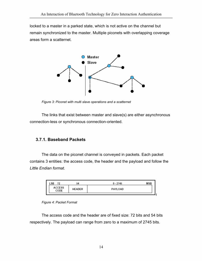
locked to a master in a parked state, which is not active on the channel but
remain synchronized to the master. Multiple piconets with overlapping coverage
areas form a scatternet.
Figure 3: Piconet with multi slave operations and a scatternet
The links that exist between master and slave(s) are either asynchronous
connection-less or synchronous connection-oriented.
3.7.1. Baseband Packets
The data on the piconet channel is conveyed in packets. Each packet
contains 3 entities: the access code, the header and the payload and follow the
Little Endian format.
t
Figure 4: Packet Format
The access code and the header are of fixed size: 72 bits and 54 bits
respectively. The payload can range from zero to a maximum of 2745 bits.

An Interaction of Bluetooth Technology for Zero Interaction Authentication
15
Different packet types have been defined. Packets may consist of access code
only, of the access code and the header only or of all of them
3.7.2. Access Code
Each packet starts with an access code. If a packet header follows, the
access code is 72 bits long, otherwise the access code is 68 bits long. This
access code is mainly use for synchronization and identification. The access
code identifies all packets exchanged on the channel of the piconet: all packets
sent in the same piconet are preceded by the same channel access code. In the
receiver of the Bluetooth unit, a sliding correlator correlates against the access
code and triggers when a threshold is exceeded. This trigger signal is used to
determine the receive timing. The access code is also used in paging and inquiry
procedures. In this case, the access code itself is used as a signaling message
and neither a header nor a payload is present.
Figure 5: Access Code format
Preamble
The preamble is a fixed zero-one pattern of 4 symbols either 1010 or
0101, depending whether the LSB of the following sync word is 1 or 0,
respectively.
Figure 6: Preamble

An Interaction of Bluetooth Technology for Zero Interaction Authentication
16
Sync Word The sync word is a 64-bit code word derived from a 24-address (LAP); for
the CAC the master’s LAP is used; for the GIAC and the DIAC, reserved,
dedicated LAPs are used; for the DAC, the slave unit LAP is used. The
construction guarantees large Hamming distance between sync words based on
different LAPs. In addition, the good auto correlation properties of the sync word
improve on the timing synchronization process.
Trailer The trailer is appended to the sync word as soon as the packet header
follows the access code. This is typically the case with the CAC, but the trailer is
also used in the DAC and IAC when these codes are used in FHS packets
exchanged during page response and inquiry response procedures. The trailer is
a fixed zero-one patter of four symbols. The trailer together with the three MSBs
of the sync word forms a 7-bit pattern of alternating ones and zeroes. The trailer
sequence is either 1010 or 0101 depending on whether the MSB of the sync
word is 0 or 1, respectively.
Figure 7: Trailer in CAC when MSB of sync word is 0 (a) and 1(b)
There are three different types of access codes defined:
• Channel Access Code (CAC)
• Device Access Code (DAC)
• Inquiry Access Code (IAC)

An Interaction of Bluetooth Technology for Zero Interaction Authentication
17
Each respective access code types are used in different operating modes
by a Bluetooth unit. The channel access code identifies a piconet and is included
in all packets exchanged on the piconet channel. The device access code is
used for special signaling procedures like paging. For the inquiry access code
there are two variations. A general inquiry access code (GIAC) is common to all
devices. The GIAC can be used to discover which other Bluetooth units are in
range. The dedicated inquiry access code (DIAC) is common for a dedicated
group of Bluetooth units that share a common characteristic. The DIAC can be
used to discover only these dedicated Bluetooth units in range.
Code Type LAP Code Length
CAC Master 72
DAC Paged unit 68/72
GIAC Reserved 68/72
DIAC Dedicated 68/72
Table 2: Access Code types
3.7.3. Packet Header
The header contains link control (LC) information and consists of 6 fields:
• AM_ADDR: 3-bit active member address
• TYPE: 4-bit type code
• FLOW: 1-bit flow control
• ARQN: 1-bit sequence number
• SEQN: 1-bit sequence number
• HEC: 8-bit header error check
Figure 8: Header format
An Interaction of Bluetooth Technology for Zero Interaction Authentication
18
AM-ADDR
The AM_ADDR represents a member address and is used to distinguish
between the active members participating on the piconet. Each member is
assigned a temporary 3-bit address to be used when it is active. Packets
exchanged between the master and the slave all carry the AM_ADDR of this
slave; that is the AM_ADDR of the slave is used in both master-to-slave packets
and in the slave-to-master packets. The all-zero address is reserved for
broadcasting packets from the master to the slaves. An exception is the FHS
which may use the all-zero member address but is not a broadcast message.
Slaves that are disconnected or parked give up their AM_ADDR. A new
AM_ADDR has to be assigned when they re-enter the piconet.
TYPE
Sixteen different types of packets can be distinguished. The 4-bit TYPE
code specifies which packet type is used. The interpretation of the TYPE code
depends on the physical link type associated with the packet. First, it shall be
determined whether the packet is sent on an SCO link or an ACL link. Then it can
be determined which type of SCO packet or ACL packet has been received. The
TYPE code also reveals how many slots the current packet will occupy. This
allows the non-addressed receivers to refrain from listening to the channel from
the duration of the remaining slots.
FLOW This bit is used for flow control of packets over the ACL link. When the
buffer for the ACL link in the recipient is full and is not emptied, a STOP
indication (FLOW=0) is returned to stop the transmission of data temporarily.
Note that the STOP signal only concerns ACL packets. Packets including only
link control information (ID, POLL and NULL Packets) or SCO packets can still

An Interaction of Bluetooth Technology for Zero Interaction Authentication
19
be received. When the buffer is empty, a GO indication (FLOW=1) is returned.
When no packet is received, or the received header is in error, a GO is assumed
implicitly. In this case, the slave can receive a new packet with cyclic redundancy
check (CRC) although its buffer is still not emptied. The slave shall then return a
NAK in response to this even if the packet passed the CRC check.
ARQN
The 1-bit acknowledgement indication ARQN is used to inform the source
of a successful transfer of payload data with CRC, and can be positive or
negative acknowledgement, ACK or NAK respectively. If the reception was
successful, an ACK (ARQN=1) is returned, otherwise a NAK (ARQN=0) is
returned. When no return message regarding acknowledgement is received, a
NAK is assumed implicitly. The ARQN is piggy-backed in the header of the return
packet. The success of the reception is checked by means of a CRC code. An
unnumbered ARQ scheme which means that the ARQN related to the latest
received packet from the same source, is used.
SEQN
The SEQN bit provides a sequential numbering scheme to order the data
packet stream. For each new transmitted packet that contains data with CRC, the
SQN bit is inverted. This is required to filter out retransmissions at the
destination; if a retransmission occurs due to a failing ACK, the destination
receives the same packet twice. By comparing the SEQN of consecutive
packets, correctly received retransmissions can be discarded.
HEC
Each header has a header-error-check to check the header integrity. The
HEC consists of an 8-bit word generated by the polynomial 647(octal

An Interaction of Bluetooth Technology for Zero Interaction Authentication
20
representation). Before generating the HEC, the HEC generator is initialized with
an 8-bit value. For FHS packets sent in master page responses state, the slave
upper address part (UAP) is used. For FHS packets sent in inquiry response, the
default check initialization is used. In all other cases, the UAO of the master
device is used. After the initialization, a HEC is calculated for the 10 header bits.
Before checking the HEC, the receiver must initialize the HEC check circuitry
with the proper 8-bit UAP (or DCI). If the HEC does not check, the entire packet
is disregarded.
3.7.4. Packet Type
The packets are used on the piconets are related to the physical links;
SCO link and ACL link, they are used in. Each link has 12 different packet types.
To indicate the different packets on a link, the 4-bit TYPE code is used. The
packet types have been divided into four segments. The first segment is reserved
for the four control packets common to all physical link types; all four packet
types have been defined. The second segment is reserved for packets occupying
a single time slot; six packet types have been defined. The third segment is
reserved for packets occupying three times slots; two packet types have been
defined. The fourth segment is reserved for packets occupying five time slots;
two packet types have been defined. The slot occupancy is reflected in the
segmentation and can directly be derived from the type code. See Appendix 1 for
a table of packets for the SCO and ACL links that was summarized above.
There are five common packets:
• ID Packet
• NULL Packet
• POLL Packet
• FHS Packet
• DM1 Packet
An Interaction of Bluetooth Technology for Zero Interaction Authentication
21
ID Packets ID Packets consist of the device access code (DAC) or inquiry access
code (IAC). It is a very robust packet since the receiver uses a bit correlator to
match the received packet to the known bit sequence of the ID packet. It has a
fixed length of 68 bits and is used in paging, inquiry, and response routines.
NULL Packet The NULL packet has no payload and therefore consists of the channel
access code and packet header only. Its total length is 126 bits. The NULL
packet is used to return link information to the source regarding the success of
the previous transmission (ARQN), or the status of the RX buffer (FLOW). The
NULL packet itself does not have to be acknowledged.
POLL Packet POLL packet is very similar to NULL packet. It doesn’t have a payload
either. However it required a confirmation from the recipient. It is not a part of the
ARQ scheme. POLL packet does not affect the ARQN and SEQN fields. Upon
reception of a POLL packet the slave must response with a packet. This packet
can be used by the master in a piconet to poll the slaves, which must respond
even if they do not have information to send.
FHS packet
FHS packet is a special control packet revealing the Bluetooth device
address and the clock of the sender. The payload contains 144 information bits
plus a 16-bit CRC code. The payload is coded with a rate 2/3 FEC which brings
the gross payload length to 240 bits. The FHS packet is used in page master

An Interaction of Bluetooth Technology for Zero Interaction Authentication
22
response, inquiry response and in master slave switch. In page master response
or master slave switch, it is retransmitted until its reception is acknowledged or a
timeout has exceeded. In inquiry response, the FHS packet is not acknowledged.
The FHS packet contains real-time clock information. This clock information is
updated before each retransmission. The retransmission of the FHS payloads is
thus somewhat different from the retransmission of ordinary data payloads where
the same payload is used for each retransmission. The FHS packet is used for
frequency hop synchronization before the piconet channel has been established,
or when an existing piconet changes to a new piconet. A picture of the FHS
packet payload format is given below. See Appendix 2 for a description of each
field of the FHS packet
Figure 9: FHS packet payload format
DM1 Packets
DM1 is used to support control messages in any link type. However it can
also carry regular user data. Since the DM1 packet is recognized on the SCO
link, it can interrupt the synchronous information to send control information. DM1
packet can also be regarded as an ACL packet
SCO Packets
SCO packets are used on the synchronous SCO links. The packets do not
include a CRC and are never retransmitted. They are routed to the synchronous
I/O (voice) port. Up to now, three pure SCO packets have been defined. In
addition an SCO packet is defined which carries an asynchronous data field in
addition to a synchronous (voice) field. The SCO packets defined so far are
An Interaction of Bluetooth Technology for Zero Interaction Authentication
23
typically used for 64 kb/s speech transmission. The SCO packets include: HV1
packet, HV2 packet, HV3 packet, and DV packet.
ACL Packets
ACL packets are used on the asynchronous links. The information carried
can be user data or control data. Including the DM1 packet, sever ACL packets
have been defined. Six of the ACL packets contain a CRC code and
retransmission is applied if no acknowledgement of proper reception is received.
The seventh ACL packet, the AUX1 packet has no CRC and is not retransmitted.
The seven ACL packets include: DM1 packet, DH1 packet, DM3 packet, DH3
packet, DM5 packet, DH5 packet, and AUX1 packet. See Appendix 3 for a
summary of the different packets.
3.7.5. Payload Format
In payload, two fields are distinguished: the (synchronous) voice field and
the (asynchronous) data field. The ACL packets only have the data field and the
SCO packets only have the voice field – with the exception of the DV packets
which have both. The voice field has a fixed length. For HV packets, the voice
field length is 240 bits; for the DV packet, the voice field length is 80 bits. No
payload header is present. The data field consists of three segments: a payload
header, a payload body and possibly a CRC code
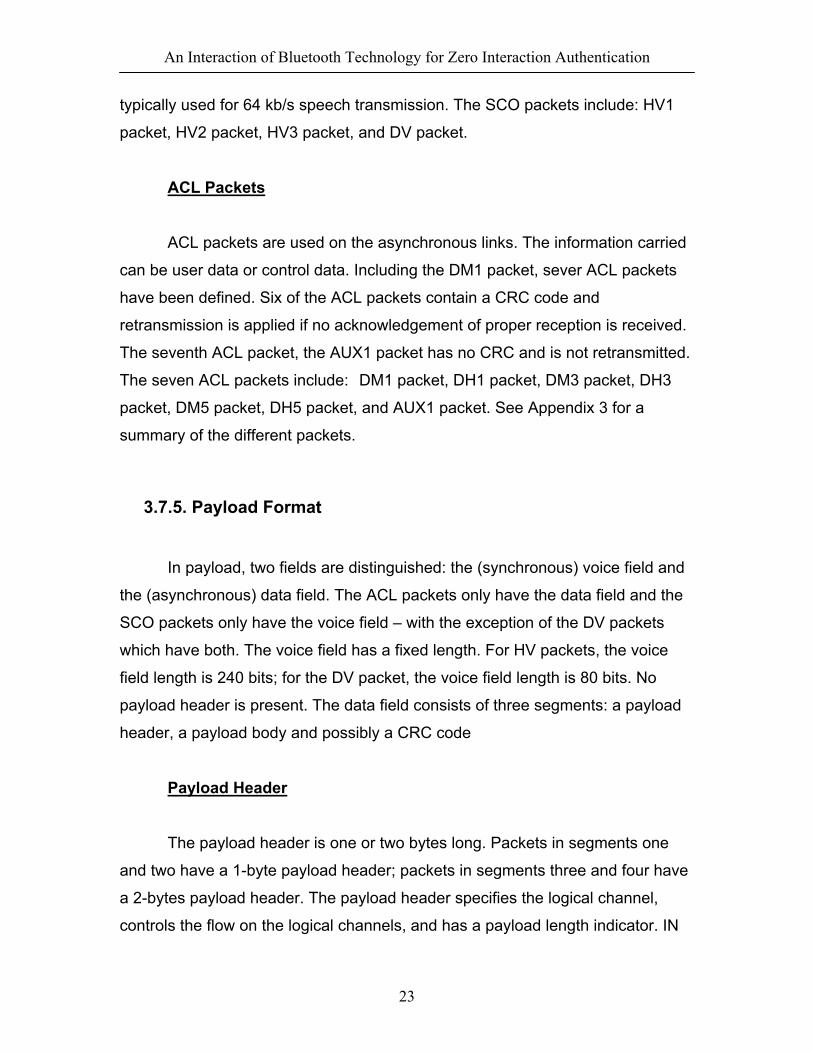
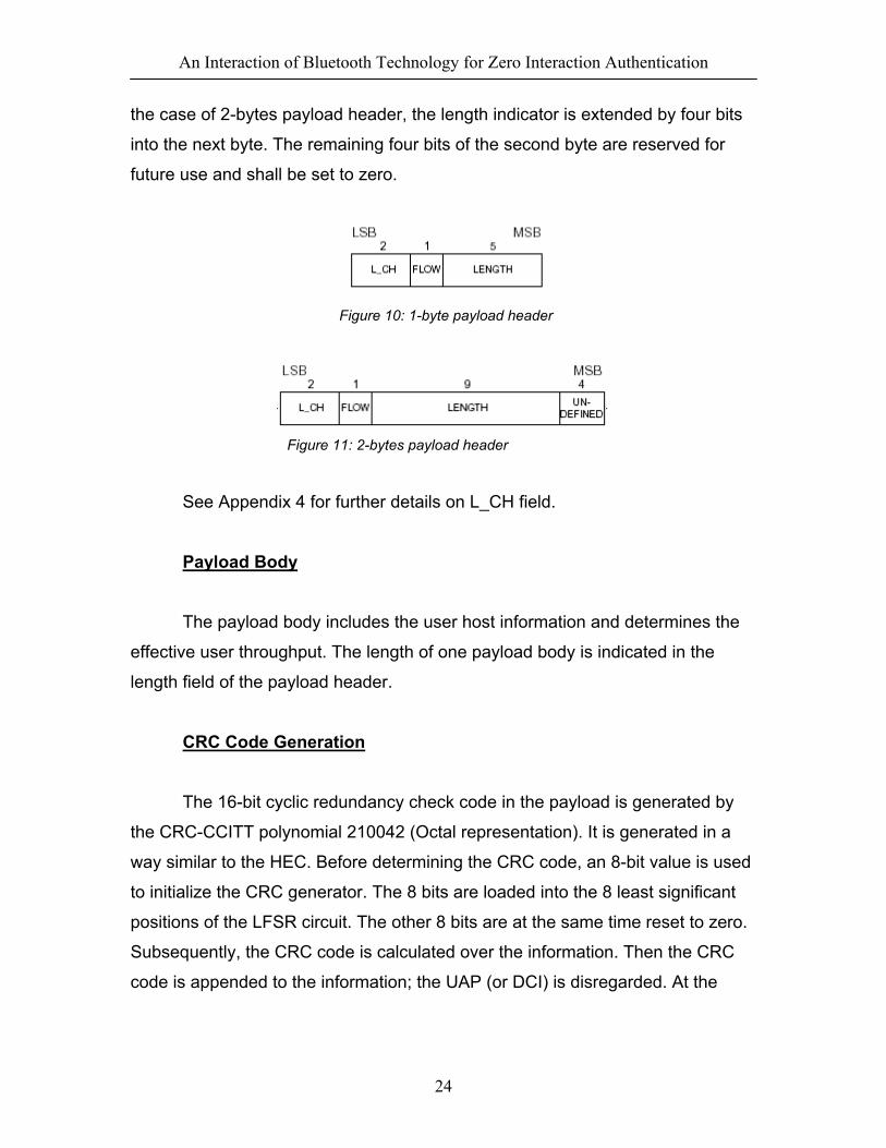
Payload Header The payload header is one or two bytes long. Packets in segments one
and two have a 1-byte payload header; packets in segments three and four have
a 2-bytes payload header. The payload header specifies the logical channel,
controls the flow on the logical channels, and has a payload length indicator. IN
An Interaction of Bluetooth Technology for Zero Interaction Authentication
24
the case of 2-bytes payload header, the length indicator is extended by four bits
into the next byte. The remaining four bits of the second byte are reserved for
future use and shall be set to zero.
Figure 10: 1-byte payload header
Figure 11: 2-bytes payload header
See Appendix 4 for further details on L_CH field.
Payload Body
The payload body includes the user host information and determines the
effective user throughput. The length of one payload body is indicated in the
length field of the payload header.
CRC Code Generation
The 16-bit cyclic redundancy check code in the payload is generated by
the CRC-CCITT polynomial 210042 (Octal representation). It is generated in a
way similar to the HEC. Before determining the CRC code, an 8-bit value is used
to initialize the CRC generator. The 8 bits are loaded into the 8 least significant
positions of the LFSR circuit. The other 8 bits are at the same time reset to zero.
Subsequently, the CRC code is calculated over the information. Then the CRC
code is appended to the information; the UAP (or DCI) is disregarded. At the

An Interaction of Bluetooth Technology for Zero Interaction Authentication
25
receive side, the CRC circuitry is in the same way initialized with the 8-bit UAP
(DCI) before the received information is checked.
Figure 12: CRC generation and checking
3.7.6. Bluetooth Connection State
The ‘Connection’ state starts with a POLL packet sent by the master to
verify the switch to the master’s timing and channel frequency hopping. The
slave can respond with any type of packet. The first information packets in the
‘Connection’ state contain control messages that characterize the link and give
more details regarding the Bluetooth units. These messages are exchanged
between the link managers of the unit. The Bluetooth units can be in several
modes of operation during the ‘Connection’ state: active mode, sniff mode, hold
mode, and park mode.
Active Mode In the active mode, the Bluetooth unit actively participates on the channel.
The master schedules the transmission based on traffic demands to and from the
different slaves. In addition, it supports regular transmissions to keep slaves
synchronized to the channel. Active slaves listen in the master-to-slave slots for
packets. If an active slave is not addressed, it may sleep until the next new

An Interaction of Bluetooth Technology for Zero Interaction Authentication
26
master transmission. Form the type indication in the packet, the number of slots
the master has reserved for its transmission can be derived; during this time, the
non-addressed slaves do not have to listen on the master-to-slave slots. A
periodic master transmission is required to keep the slaves synchronized to the
channel. Since the slaves only need the channel access code to synchronize
with, any packet type can be used for this purpose.
Sniff Mode In the sniff mode, the duty cycle of the slave’s listen activity can be
reduced. If a slave participates on an ACL link, it has to listen in every ACL slot to
the master traffic. With the sniff mode, the time slots where the master can start
transmission to a specific slave is reduced; that is the master can only start
transmission in specified time slots. These so-called sniff slots are spaced
regularly. The slave starts listening at the sniff slots for N consecutive receive
slots unless a packet with matching AM_ADDR is received. After every reception
of a packet with matching AM_ADDR, the slave continues listening at the
subsequent N or remaining of the receive slots, whichever is greater. So for N >
0, the slave continues listening as long as it receives packets with matching
AM_ADDR. To enter the sniff mode, the master or the slave shall issue a sniff
command via the LM protocol. This message will contain the sniff interval T and
an offset D. The timing of the sniff mode is then determined similar as for the
SCO links.
Hold Mode During the ‘Connection’ state, the ACL link to a slave can be put in a hold
mode. This means that the slave temporarily does not support ACL packets on
the channel any more. With the hold mode, capacity can be made free to do
other things like scanning, inquiring, or attending another piconet. The unit in
hold mode can also enter a low-power sleep mode. During the hold mode, the

An Interaction of Bluetooth Technology for Zero Interaction Authentication
27
slave unit keeps its active member address (AM_ADDR).Prior to entering the
hold mode, master and slave agree on the time duration the slave remains in the
hold mode. A timer is initialized with the ‘holdTO’ value. When the timer is
expired, the slave will wake up, synchronize to the traffic on the channel and will
wait for further instructions.
Park Mode When a slave does not need to participate on the piconet channel, but still
wants to remain synchronized to the channel, it can enter the park mode which is
a low-power mode with very little activity in the slave. In the park mode, the slave
gives up its active member address AM_ADDR. Instead, it received two new
addresses to be used in the park mode:
• PM_ADDR: 8-bit Parked Member Address
• AR_ADDR: 8-bit Access Request Address
The PM_ADDR distinguishes a parked slave from the other parked slaves.
This address is used in the master-initiated unpark procedure. In addition to the
PM_ADDR, a parked slave can also be unparked by its 48-bit BD_ADDR. The
all-zero PM_ADDR is reserved address: if a parked unit has the all-zero
PM_ADDR it can only be unparked by the BD_ADDR. In that case, the
PM_ADDR has no meaning. The AR_ADDR is used by the slave in the slave-
initiated unpark procedure. All messages sent to the parked slaves have to be
carried by the broadcast packets (the all-zero AM_ADDR) because of the
missing AM_ADDR.
3.7.7. Bluetooth Addressing
Bluetooth Device Address (BD_ADDR)

An Interaction of Bluetooth Technology for Zero Interaction Authentication
28
Each Bluetooth transceiver is allocated a unique 48-bit Bluetooth device
address (BD_ADDR). This address is derived from the IEEE802 standard. This
48-bit address is divided into three fields:
• LAP field: lower address part consisting of 24 bits
• UAP field: Upper address part consisting of 8 bits
• NAP field: non-significant address part consisting of 16 bits
Figure 13: Format of BD_ADDR
Active Member Address (AM_ADDR) Each slave active in a piconet is assigned a 3-bit active member address
(AM_ADDR). The all-zero AM_ADDR is reserved for broadcast messages. The
master doesn’t have an AM_ADDR. Its timing relative to the slaves distinguishes
it from the slaves. A slave only accepts a packet with a matching AM_ADDR and
broadcast packets. The AM_ADDR is carried in the packet header. The
AM_ADDR is only valid as long as a slave is active on the channel. The
AM_ADDR is lost as soon as it is disconnected or parked. The AM_ADDR is
assigned by the master to the slave when the slave is activated. This is either at
connection establishment or when the slave is unparked. At connection
establishment, the AM_ADDR is carried in the FHS payload. When unparking,
the AM_ADDR is carried in the unpark message.
Parked Member Address (PM_ADDR) A slave in park mode can be identified by its BD_ADDR or by a dedicated
parked member address (PM_ADDR). This latter address is an 8-bit member
address that separates the parked slaves. The PM_ADDR is only valid as long

An Interaction of Bluetooth Technology for Zero Interaction Authentication
29
as the slave is parked. When the slave is activated it is assigned an AM_ADDR
but loses the PM_ADDR. The PM_ADDR is assigned to the slave the moment it
is parked. The all-zero PM_ADDR is reserved for parked slaves that only use
their BD_ADDR to be unparked.
Access Request Address (AR_ADDR) The access request address is used by the parked slave to determine the
slave-to-master half slot in the access window it is allowed to send access
request messages in. The AR_ADDR is assigned to the slave when it enters the
park mode and is only valid as long as the slave is parked. The AR_ADDR is not
necessarily unique, that is different parked slaves may have the same
AR_ADDR.
3.8. Link Manager Protocol
The Link Manager Protocol is used for link setup and control process in
which two devices transfer handshaking information. The signals are interpreted
and filtered out by the Link Manager on the receiving side and are not
propagated to higher layers. Link Manager Messages have higher priorities that
user data. This means that if the Link Manager needs to send a message, it shall
not be delayed by the L2CAP traffic, although it can be delayed by many
retransmissions of individual baseband packets.

An Interaction of Bluetooth Technology for Zero Interaction Authentication
30
Figure 14: Link Manager
3.9. Logical Link Control and Adaptation Protocol
L2CAP provides connection-oriented and connectionless data services to
upper layer protocols with protocol multiplexing capacity, segmentation and
reassembly operation, and group abstraction. L2CAP permits higher level
protocols and applications to transmit and receive L2CAP data packets up to 64
Kilobytes in length, since it supports Internet Protocol (IP) datagrams.
Figure 15: L2CAP with protocol layers

An Interaction of Bluetooth Technology for Zero Interaction Authentication
31
L2CAP can be viewed as working in parallel with LMP and is defined for
only ACL and no support for SCO links is planned. L2CAP provides a reliable
channel using the mechanisms available at the Baseband layer. L2CAP is based
around the concept of ‘channels’. Each one of the end-points of the L2CAP
channel is referred to as a channel identifier.
3.10. Service Discovery Protocol
Service Discovery Protocol is part of LMP. It provides a means for
applications to discover which services are available and to determine the
characteristics of those available services, a necessary first step before a
connection between two devices can occur. SDP uses a request/response model
where each transaction consists of one request protocol data unit (PDU) and one
response PDU. The SDP protocol transfers multiple-byte fields in standard
network byte order (Big Endian), with more significant (high-order) bytes being
transferred before less significant (low-order) bytes.
Figure 16: SDP configuration

An Interaction of Bluetooth Technology for Zero Interaction Authentication
32
4. Design
The main focus of the design section will be around device discovery
since it allows the automatic detection of proximate Bluetooth devices, and this
service is provided by the Host Controller Interface (HCI) of Bluetooth. The
device discovery allows a Bluetooth device to detect other proximate Bluetooth
devices within 10m range. This service can be automated, in the sense that the
Bluetooth device can be made to automatically detect other devices.
4.1 Host Controller Interface (HCI)
The HCI provides a command interface to the baseband controller and link
manager, and access to hardware status and control registers. This interface
provides a uniform method for access the Bluetooth baseband capabilities.
Figure 17: Bluetooth Hardware Architecture
The Link controller (LC) consists of hardware and software parts that
perform Bluetooth baseband processing, and physical layer protocols such as
ARQ-protocol and FEC coding.
The CPU core will allow the Bluetooth module to handle inquiries and filter
page requests without involving the host device. The Host Controller can be
programmed to answer certain Page messages and authenticate remote links.

An Interaction of Bluetooth Technology for Zero Interaction Authentication
33
The Link Manager (LM) software runs on the CPU Core. Te LM discovers
other remote LMs and communicates with them via the Link Manager Protocol
(LMP) to perform its service provider role using the services of the underlying
Link Controller (LC).
4.1.1. USB HCI Architecture
Bluetooth devices have various physical bus interfaces that could be used
to connect to the Bluetooth hardware. These buses may have different
architectures and different parameters. The Bluetooth Host Controller will initially
support two physical bus architectures, USB and PC card.
USB can handle several login channels over the same single physical
channel (via Endpoints). Therefore control, data, and voice channels do not
require any additional physical interfaces. There is no direct access to registers/
memory on the Bluetooth module over USB. Instead, this is done by using the
appropriate HCI Commands and by using the Host Controller Transport Layer
interface.
Figure 18: Bluetooth block diagram with USB HCI
Besides the USB interface derivatives of the ISA bus (Compact Flash/PC
Card interfaces) are an option for an integrated PC solution. Unlike USB, all
traffic between the Host and the Bluetooth module will go across the PC Card
bus interface. Communications between the host PC and the Bluetooth module
will be primarily done directly via registers/memory.

An Interaction of Bluetooth Technology for Zero Interaction Authentication
34
Figure 19: Bluetooth block diagram with PC-Card HCI
4.1.2. HCI Commands
HCI provides a uniform command method of accessing the Bluetooth
hardware capabilities. The HCI Link commands provide the Host with the ability
to control the link layer connections to other Bluetooth devices. These commands
typically involve the Link Manager (LM) to exchange LMP commands with remote
Bluetooth devices.
The HCI policy commands are used to affect the behaviour of the local
and remove LM. These policy commands provide the Host with methods of
influencing how the LM manages the piconet. The Host Controller & Baseband,
Informational, and Status commands provide the Host access to various registers
in the Host Controller.
HCI commands may take different amounts of time to be completed.
Therefore, the results of commands will be reported back to the Host in the form
of an event. This event contains the return parameters for the completed HCI
command. For enabling the Host to detect errors on the HCI-Transport Layer,
there needs to be a timeout between the transmission of the Host’s command
and the reception of the Host Controller’s response.
4.1.3. HCI Command Packets
The HCI Command Packets are used to send commands to the Host
Controller from the Host. When the Host Controller completes most of the

An Interaction of Bluetooth Technology for Zero Interaction Authentication
35
commands, a Command Complete event is sent to the Host. Some commands
do not receive a Command Complete event when they have been completed.
Instead, when the Host Controller receives one of these commands the Host
Controller sends a Command Status event back to the Host when it has begun to
execute the command. Later on, when the actions associated with the command
have finished, an event that is associated with the sent command will be sent by
the Host Controller to the Host. However, if the command doesn’t begin to
execute, the event associated with the sent command will not be returned. The
Command Status event will, in this case, return the appropriate error code in the
Status parameter. On initial power-on, and after a reset, the Host can send a
maximum of one outstanding HCI Command Packet until a Command Complete
or Command Status event has been received. If an error occurs for a command
for which a Command Complete event is returned, the Return_Parameters field
may not contain all the return parameters specified for the command. The Status
parameter, which explains the error reason and which is the first return
parameter, will always be returned. If there is a Connection_Handle parameter or
a BD_ADDR parameter right after the Status parameter, this parameter will also
be returned so that the Host can identify to which instance of a command the
Command Complete even belongs. On this case, the Connection_Handle or
BD_ADDR parameter will have exactly the same value as that in the
corresponding command parameter.
If an error occurs for a command for which no Command Complete event
is returned, all parameters returned with the event associated with this command
may not be valid. The Host must take care as to which parameters may have
valid values depending on the value of the Status parameter of the Complete
event associated with the given command. The Command Completer and
Command Status events contain a parameter called
Num_HCI_Command_Packets, which indicates the number of HCI Command
Packets the Host is currently allowed to send to the Host Controller. The Host
Controller may buffer one or more HCI command packets, but the Host Controller

An Interaction of Bluetooth Technology for Zero Interaction Authentication
36
must start performing the commands in the order in which they are received. The
host Controller can start performing a command before it completes previous
commands. Therefore, the commands do not always complete in the order they
are started. The Host Controller must be able to accept HCI Command Packets
with up to 255 bytes of data excluding the HCI Command Packet Header.
Each command is assigned a 2 byte Opcode used to uniquely identify
different types of commands. The Opcode parameter is divided into two fields,
called the OpCode Group Field (OGF) and OpCode Command Field (OCF). The
OGF occupied the upper 6 bits of the Opcode, while the OCF occupies the
remaining 10 bits. The OGF of 0x3E is reserved for Bluetooth Logo Testing. The
organization of the Opcodes allows additional information to be inferred without
fully decoding the entire Opcode.
Figure 20: HCI Command Packet
See Appendix 6 for description of each field in the HCI Command packet.
4.1.4. HCI Event Packet
HCI Event Packet is used by the Host Controller to notify the Host when
event occur. The Host must be able to accept HCI Event packets with up to 255
bytes of data excluding the HCI Event Packet header.

An Interaction of Bluetooth Technology for Zero Interaction Authentication
37
Figure 21: HCI Event Packet
See Appendix 7 for description of each field in the HCI Event packet.
4.1.5. HCI Data Packet
HCI Data Packets are used to exchange data between the Host and Host
Controller. The data packets are defined for both ACL and SCO data types.
Figure 22: HCI ACL Data Packet
See Appendix 8 for description of each field in HCI ACL data packet.
Figure 23: HCI SCO Data Packet
An Interaction of Bluetooth Technology for Zero Interaction Authentication
38
See Appendix 9 for description of each field in HCI SCO data packet.
4.2. Other HCI Commands & Parameters
Link Control Commands The link Control commands allows the Host Controller to control
connections to other Bluetooth devices. When the Link Control commands are
used, the Link manager controls how the Bluetooth piconets and scatternets are
established and maintained. These commands instruct the LM to create a modify
link layer connections with Bluetooth remote devices, perform inquiries of other
Bluetooth devices in range, and other LMP Commands. See Appendix 10 for
details on the Link Control Commands.
Link Policy Commands The Link Policy commands provide methods for the Host to affect how the
Link Manager manages the piconet. When Link Policy Commands are used, the
LM still controls how Bluetooth piconets and scatternets are established and
maintained, depending on adjustable policy parameters. These policy commands
modify the Link Manager behaviour that can result in changes to the link layer
connections with Bluetooth remote devices. See Appendix 11 for details on the
Link Policy Commands.
Host Controller & Baseband Commands The Host Controller & Baseband Commands provide access and control
to various capabilities of the Bluetooth hardware. These parameters provide
control of Bluetooth devices and of the capabilities of the Host Controller, Link
Manager, and Baseband. The host device can use these commands to modify
the behaviour of the local device. See Appendix 12 for details on the Host
Controller & Baseband Commands.
An Interaction of Bluetooth Technology for Zero Interaction Authentication
39
Informational Parameters The Informational Parameters are fixed by the manufacturer of the
Bluetooth hardware. These parameters provide information about the Bluetooth
device and the capabilities of the Host Controller, Link Manager, and Baseband.
The host device cannot modify any of these parameters. See Appendix 13 for
details on the Information Parameters.
Status Parameters The Host Controller modifies all status parameters. These parameters
provide information about the current state of the Host Controller, Link Manager,
and Baseband. The host device cannot modify any of these parameters other
than to reset certain specific parameters. See Appendix 14 for details on the
Status Parameters.
Testing Commands The Testing commands are used to provide the ability to test various
functionalities of the Bluetooth hardware. These commands provide the ability to
arrange various conditions for testing. See Appendix 15 for details on the Testing
Commands.
4.3. Events
Events are used in Host Controller Interface to indicate the completion of a
process. See Appendix 16 for a listings of those events.
4.4. Main Implementation Process

An Interaction of Bluetooth Technology for Zero Interaction Authentication
40
The easiest way to explain the implementation process is through a
message sequence chart.
Figure 24: MSC of Device Inquiry
Inquiry is used to detect and collect nearby BT Devices. When receiving
the command HCI_Inquiry (LAP, Inquiry_Length, Num_Responses), HC will start
the baseband inquiry procedure with an Inquiry Access Code (derived from the
specified LAP) and Inquiry Length. When Inquiry Responses are received, HC

An Interaction of Bluetooth Technology for Zero Interaction Authentication
41
will filter out and then return the information related to the found BT Devices
using one of (Num_Responses, BD_ADDR[i], Page_Scan_Repetition_Mode[i],
Page_Scan_Period_Mode[i], Page_Scan_Mode[i], Class_Of_Device[i],
Clock_Offset[i]) to the Host. The filtering of found BT Devices is specified in
HCI_Set_Event_Filter (Filter_Type, Filter_Condition_Type, Condition) with the
Filter_Type = Inquiry Result. When the Inquiry procedure is completed, Inquiry
Complete event (Status) must be returned to the Host. Otherwise, the command
HCI_Inquiry_Cancel() will be used to directly stop the inquiry procedure. If the
Inquiry Complete event is fired, the BD_ADDR can be used to uniquely identify
each device and hence each user and then loads user-defined configuration.
Using same BD_ADDR, we can know which user-defined application to load
when user walks away.
4.5. Automation process
The inquiry process is a one-time inquiry process, meaning that in order
for a Bluetooth Device to constantly look for any nearby Bluetooth device, the
inquiry process won’t do. Fortunately there is an option that comes along the
Interface that allows constant inquiry. However this option performs inquiry every
1 minute best time.
The device inquiry as you might have already guessed doesn’t involve any
connection between devices and that is why it is possible to perform automation.
For a connection to be established using one of the Bluetooth protocols (L2CAP,
LMP, SDP), there need to be something sent between the devices, otherwise no
connection will be created. It doesn’t mean that we cannot create a connection
for this project, but it will not be very efficient because each time for the software
to work, i.e. to detect a user, the user will have to send in a packet to the Host
device.
Steps to start the automatic inquiry mode

An Interaction of Bluetooth Technology for Zero Interaction Authentication
42
• Double click on the Bluetooth icon to open “My Bluetooth Places”.
• Click on the ‘Bluetooth’ option, and select ‘Device Configuration’.
• Select the Discovery tab.
• On that page, check the checkbox ‘Look for other Bluetooth device’ and
specify an integer representing minutes in the text field. (minimum is 1)
4.6. User-Defined Application
A very simple user-defined application that can be used is a screensaver.
So when the user walks away of the host, the host will launch a user-defined
screensaver, when performing an inquiry and not detecting the device
anymore. The code to launch screensavers has been created in C++. There
are 2 main functions: StartScreenSaver() and StopScreenSaver().
The StartScreenSaver() take a screensaver handle and initialize it, which
will then start the screensaver. Right now, the function is set to work if a
screen saver has been set in the control panel, but it can be change to work
with a user-defined screensaver. The StopScreenSaver() takes the initialized
handle and terminates it and set it to null.
4.7. Summary
To summarize the whole implementation process, I will use a small Use
case diagram and a state machine and a small pseudo-code to make it as
clear as possible.
Pseudo-code: Automate
Perform DeviceInquiry (BD_ADDR)

An Interaction of Bluetooth Technology for Zero Interaction Authentication
43
if BD_ADDR is registered and is new then
load new user configuration
end if
if BD_ADDR is registered and is not new then
do nothing
end if
if BD_ADDR is not found then
load previous BD_ADDR user-defined application
end if
if BD_ADDR is not registered then
do nothing and remain in previous state
end if
End automation
Use Case Diagram:
Figure 25: Use Case diagram of system
Moves away Bluetooth PDA
User
Brings in Bluetooth PDA
Logging in Workstation
Load user-defined application
<Includes>
Load user configuration

An Interaction of Bluetooth Technology for Zero Interaction Authentication
44
State Machine:
Figure 26: State Machine
Initial
Configuration loaded
User-defined application loaded
Detects registered device
Detects unregistered device
No longer detects registered device
Detects new unregistered device
Detects new registered device
Detects new registered device
Detects new unregistered device
Detects new unregistered device

An Interaction of Bluetooth Technology for Zero Interaction Authentication
45
5. Discussion
In this section, I will describe in 4 steps how to create device discovery
with java APIs for Bluetooth Wireless Technology (JAWBT). JAWBT uses the
J2ME technologies and it can be obtain from
http://java.sun.com/j2me/download.html
Classes used from API:
• class javax.bluetooth.LocalDevice
• interface javax.bluetooth.DiscoveryListener
• class javax.bluetooth.DiscoveryAgent
• class javax.bluetooth.RemoteDevice
• class javax.bluetooth.DeviceClass
The 4 steps:
• Get a DiscoveryAgent from your LocalDevice
• Implement the DiscoveryListener interface
• Use your DiscoveryAgent to initiate a search, the listener will
receive notification of events
• Check that the discovered devices are what your looking for
Step 1 The following code snippet would be part of a MIDlet. To prevent blocking
it should be run in thread. The BluetoothStateException is thrown when the
device cannot honour a request made to it because of its state.
// Preamble setting up MIDlet etc.
try {
// Get the agent using methods on the LocalDevice
DiscoveryAgent ourAgent = LocalDevice.getLocalDevice().getDiscoveryAgent();

An Interaction of Bluetooth Technology for Zero Interaction Authentication
46
LocalDevice.getLocalDevice().getDiscoveryAgent();
} catch(BluetoothStateException bse)P
Alert exAlert = new Alert(“Uh-Oh!”,bse.toString(),null,null);
exAlert.setTimeout(Alert.FOREVER);
}
Step 2 Implement the DiscoveryListener interface so that devices discovered may
be returned and events handled. The DiscoveryListener is used in both device
and service discovery but for the time being we are only concerned only with the
device discovery elements of the interface.
Public class OurListener implements DiscoveryListener{
Private RemoveDevice remDev = null;
Private DeviceClass remDevClass = null;
// All we’re doing in storing the first device discovered and its class code
Public void deviceDiscovered (RemoteDevice btDevice, DeviceClass cod)
{
remDev = btDevice;
remDevClass = cod;
// call devicechecker() here to see if its what we really want a Bluetooth
device
}
Public void inquiryCompleted(int discType){}
Public void serviceDiscovered(int transID, ServiceRecord[] servRecord){}
Public void serviceSearchCompleted
}
The InquiryComplete method is used by a developer in a full (real)
implementation of a listener to define what happens when an inquiry is stopped,
completes or ceases because of a problem. There are a number of statics
defines that are passed to InquiryComplete which the developer can handle as
they see fit, e.g if the method received an INQUIRY_ERROR constant we may
wish to alert the user and return to the previous state, for example, roll back and
redo the transaction hoping the same thing doesn’t happen again.

An Interaction of Bluetooth Technology for Zero Interaction Authentication
47
Step 3 Now that we have an agent and implemented the listener we can place
our device in “Inquiry Mode” and use our radio to look for devices listening in our
vicinity. The startInquiry method is used to perform this action, but we do not
have to initiate a radio search if we don’t think it is necessary, as it takes time.
We can retrieve remote device information previously stored on our device by
using RemoteDevice[] remDevArray = ourAgent.retrieveDevices(DiscoveryAgent.CACHED);
Or
RemoteDevice[] remDevArray =
ourAgent.retrieveDevices(DiscoveryAgent.PREKNOWN);
CACHED means to search our device for remote devices found in the last
inquiry, PREKNOWN means to search for devices our device frequently
accesses.
The radio inquiry (non-blocking) asynchronously calls you back through
deviceDiscovered where we perform checks on discovered devices and store
them away.
// this continue on from the DiscoveryAgent snippet earlier
OurListener listener = new OurListener();
Try {
// we have an agent, let us start the inquiry
// we register this inquiry with our “listener”
ourAgent.startInquiry(DiscoveryAgent.GIAC,listener);
} catch (BluetoothStateException bse){
Alert exAlert = new Alert( “Uh-Oh! Problem with Inquiry!”, bse.toString(),null, null);
exAlert.setTimeout(Alert.FOREVER);
}
Step 4
An Interaction of Bluetooth Technology for Zero Interaction Authentication
48
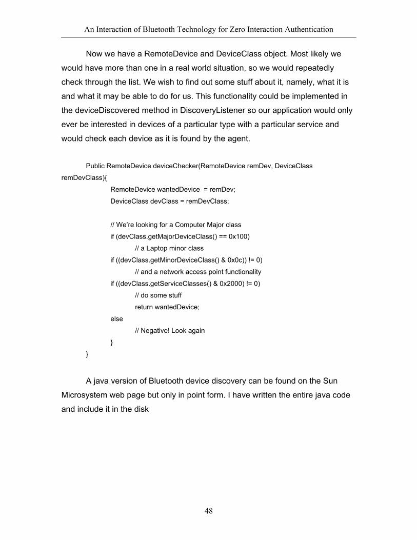
Now we have a RemoteDevice and DeviceClass object. Most likely we
would have more than one in a real world situation, so we would repeatedly
check through the list. We wish to find out some stuff about it, namely, what it is
and what it may be able to do for us. This functionality could be implemented in
the deviceDiscovered method in DiscoveryListener so our application would only
ever be interested in devices of a particular type with a particular service and
would check each device as it is found by the agent.
Public RemoteDevice deviceChecker(RemoteDevice remDev, DeviceClass
remDevClass){
RemoteDevice wantedDevice = remDev;
DeviceClass devClass = remDevClass;
// We’re looking for a Computer Major class
if (devClass.getMajorDeviceClass() == 0x100)
// a Laptop minor class
if ((devClass.getMinorDeviceClass() & 0x0c)) != 0)
// and a network access point functionality
if ((devClass.getServiceClasses() & 0x2000) != 0)
// do some stuff
return wantedDevice;
else
// Negative! Look again
}
}
A java version of Bluetooth device discovery can be found on the Sun
Microsystem web page but only in point form. I have written the entire java code
and include it in the disk
An Interaction of Bluetooth Technology for Zero Interaction Authentication
49
6. Conclusions and Proposal for future work
The main difficulty in this project was to access the HCI functions. There
are 2 ways of solving this problem. The first and easiest one is to purchase the
SDK for the Bluetooth Stack. The SDK provides functions that will enable easy
access to those HCI functions without having to manipulate these functions
directly. The other solution is to use the HCI functions directly and here your best
ally is the Bluetooth Specification provided by Bluetooth SIG, as the list of all the
‘HEX’ code necessary to manipulate these function are given there. So if
someone actually wants to continue this project and create the software, he/she
will have to take either way. The main disadvantage of the first option is that the
SDK is being commercialized by WIDCOMM Inc for about US$ 800 and the main
disadvantage of the second option is that he/she will have to know COM
programming which is not that easy. Below is a snapshot of the HCI functions
that can be viewed using the OLE/COM Object Viewer from MS Platform SDK

An Interaction of Bluetooth Technology for Zero Interaction Authentication
50
Figure 27: Snapshot of HCI Commands
My research work has been mainly focused on Device Inquiry. However
there might be another way of doing it by establishing a ‘Connection’ between
Bluetooth devices which I didn’t really consider. So some research on that area
also might be interesting.

An Interaction of Bluetooth Technology for Zero Interaction Authentication
51
7. References
• Berggren. M., Wireless communication in telemedicine using Bluetooth
and IEEE 802.11b
• Bhatt. P., Bluetooth, TATA Consultancy Services
• Bluetooth SIG, Inc, Specification of the Bluetooth System,
www.bluetooth.com
• Held. G., Data Over Wireless Networks; Bluetooth, WAP & Wireless
LANs, pp. 210-221
• Sun Microsystems, http://java.sun.com/j2me/download.html
• Widcomm Inc., www.widcomm.com

An Interaction of Bluetooth Technology for Zero Interaction Authentication
52
Appendix 1
Segment TYPE code Slot occupancy SCO link ACL link
0000 1 NULL NULL
0001 1 POLL POLL
0010 1 FHS FHS 1
0011 1 DM1 DM1
0100 1 undefined DH1
0101 1 HV1 undefined
0110 1 HV2 undefined
0111 1 HV3 undefined
1000 1 DV undefined
2
1001 1 undefined AUX1
1010 3 undefined DM3
1011 3 undefined DH3
1100 3 undefined undefined 3
1101 3 undefined undefined

An Interaction of Bluetooth Technology for Zero Interaction Authentication
53
1110 5 undefined DM5 4
1111 5 undefined DH5
Table 3: Packets defined for SCO and ACL link pages
Appendix 2
Parity Bits 34-bit field that contains the parity bits that form the first part of the
sync word of the access code of the unit that sends the FHS packet.
These bits are derived from the LAP.
LAP 24-bit field that contains the lower address part of the unit that sends
the FHS packet
Undefined 2-bit field that is reserved for future use and shall be set to zero
SR 2-bit field that is the scan repetition field and indicates the interval
between two consecutive page scan windows
SP 2-bit field that is the scan period field and indicates the period in
which the mandatory page scan mode is applied after transmission
of an inquiry response message
UAP 8-bit field that contains the upper address part of the unit that sends
the FHS packet
NAP 16-bit field that contains the non-significant address part of the unit
that sends the FHS packet

An Interaction of Bluetooth Technology for Zero Interaction Authentication
54
Class of device
24-bit field that contains the class of device of the unit that sends the
FHS packet. This field is defined in Bluetooth assigned Numbers
AM_ADDR
3-bit field that contains the member address the recipient shall use if
the FHS packet is used at call setup or master-slave switch. A slave
responding to a master or a unit responding to an inquiry request
message shall include an all-zero AM_ADDR field if it sends the
FHS packet
CLK(27-2)
26-bit field that contains the value of the native system clock of the
unit that sends the FHS packet, sampled at the beginning of the
retransmission of the access code of this FHS packet. This clock
value has a resolution of 1.25ms. For each new transmission, this
field is update so that it accurately reflects the real-time clock value
Page Scan Mode
3-bit field that indicates which scan mode is used by default by the
sender of the FHS packet. Currently the standard supports one
mandatory scan mode and up to three optional scan modes
Table 4: Description of FHS packet payload
SR bit format SR mode
00 R0
01 R1
10 R2
11 Reserved
Table 5: Contents of SR field
SP bit format SP mode
00 P0
01 P1
10 P2
11 Reserved
Table 6: Contents of SP field
Bit format Page Scan mode
000 Mandatory scan mode
001 Optional scan mode 1

An Interaction of Bluetooth Technology for Zero Interaction Authentication
55
010 Optional scan mode 2
011 Optional scan mode 3
100 Reserved for future use
101 Reserved for future use
110 Reserved for future use
111 Reserved for future use
Table 7: Contents of page scan mode field
Appendix 3
Type User Payload (bytes) FEC CRC Symmetric Max. Rate
Asymmetric Max. Rate
ID N/A N/A N/A N/A N/A
NULL N/A N/A N/A N/A N/A
POLL N/A N/A N/A N/A N/A
FHS 18 2/3 Yes N/A N/A
Table 8: Link Control Packets
Asymmetric Max.
Rate (Kb/s) Type Payload Header (bytes)
User Payload (bytes)
FEC CRC Symmetric Max. Rate
(Kb/s) Forward Reverse
DM1 1 0-17 2/3 Yes 108.8 108.8 108.8
DH1 1 0-27 no Yes 172.8 172.8 172.8
DM3 2 0-121 2/3 Yes 258.1 387.2 54.4
DH3 2 0-183 No Yes 390.4 585.6 86.4

An Interaction of Bluetooth Technology for Zero Interaction Authentication
56
DM5 2 0-224 2/3 Yes 286.7 477.8 36.3
DH5 2 0-339 No Yes 433.9 723.2 57.6
AUX1 1 0-29 No No 185.6 185.6 185.6
Table 9: ACL packets
Type Payload
Header (bytes) User Payload
(bytes) FEC CRC
Symmetric Max. Rate (Kb/s)
HV1 N/A 10 1/3 No 64.0
HV2 N/A 20 2/3 No 64.0
HV3 N/A 30 No No 64.0
DV* 1 D 10 + (0.9) D 2/3 D Yes D 64.0 + 57.6 D
Table 10: SCO packets
* Items followed by ‘D’ relates to data field only
Appendix 4
L_CH code Logical Channel Information 00 N/A Undefined
01 UA/UI Continuation fragment of an L2CAP message
10 UA/UI Start of an L2CAP message or no fragmentation
11 LM LMP message
Table 11: Logical channel L_CH field contents

An Interaction of Bluetooth Technology for Zero Interaction Authentication
57
Appendix 5
CID Description 0x0000 Null Identifier 0x0001 Signaling channel 0x0002 Connectionless reception channel
0x0003 – 0x003F Reserved 0x0004 – 0xFFFF Dynamically allocated
Table 12: CID Definitions

An Interaction of Bluetooth Technology for Zero Interaction Authentication
58
Appendix 6 Op_Code: Size: 2 Bytes
Value Parameter Description
0xXXX OGFRange (6 bits): 0x00 – 0x3F (0x3E reserved for Bluetooth logo
testing and 0x3F reserved for vendor-specific debug commands)
OCF Range (10 bits): 0x0000 – 0x03FF
Table 13: Command Packet Op_Code
Parameter_Total_Length: Size: 1 Byte
Value Parameter Description
0xXX Lengths of all the parameters contained in this packet measured in
bytes. (N.B: total length of parameters, not number of parameters)
Table 14: Command Packet Parameter_Total _Length
Parameter 0 - N: Size: Parameter Total Length

An Interaction of Bluetooth Technology for Zero Interaction Authentication
59
Value Parameter Description
0xXX Each command has a specific number of parameters associated with
it. These parameters and the size of each of the parameters are
defined for each command. Each parameter is an integer number of
bytes in size
Table 15: Command Packet Parameter
Appendix 7 Event_Code: Size: 1 Byte
Value Parameter Description
0xXX Each event is assigned a 1-Byte event code used to uniquely identify
different types of events.
Range: 0x00 – 0xFF
Table 16: Event Packet Op_Code
Parameter_Total_Length: Size: 1 Byte
Value Parameter Description
0xXX Lengths of all the parameters contained in this packet measured in
bytes. (N.B: total length of parameters, not number of parameters)
Table 17: Event Packet Parameter_Total_Length

An Interaction of Bluetooth Technology for Zero Interaction Authentication
60
Event_Parameter 0 - N: Size: Parameter Total Length
Value Parameter Description
0xXX Each event has a specific number of parameters associated with it.
These parameters and the size of each of the parameters are defined
for each command. Each parameter is an integer number of bytes in
size
Table 18: Event Packet Parameter
Appendix 8 Connection_Handle: Size: 12 Bits
Value Parameter Description
0xXXXX Connection Handle to be used for transmitting a data packet or
segment.
Range 0x0000 – 0x0EFF
Table 19: HCI ACL Data packet Connection_Handle
Flags (Size: 2 Bits). The Flag Bits consist of the Packet_Boundary_Flag and
Broadcast_Flag. The Packet_Boundary_Flag is located in bit 4 and bit 5, and the Broadcast_Flag
is located in bit 6 and 7 in the second byte of the HCI ACL Data packet.
Packet_Boundary_Flag: Size: 2 Bits

An Interaction of Bluetooth Technology for Zero Interaction Authentication
61
Value Parameter Description
00 Reserved for future use
01 Continuing fragment packet of Higher Layer Message
10 First packet of Higher Layer Message (i.e. start of an L2CAP packet)
11 Reserved for future use
Table 20: HCI ACL Data packet Packet_Boundary_Flag
Broadcast_Flag (in packet from Host to Host Controller): Size: 2 Bits
Value Parameter Description
00 No broadcast. Only point-to-point
01 Active Broadcast: Packet is sent to all active slaves (i.e. packet is
usually not sent during park beacon slots), and it may be received by
slaves in sniff or park mode
10 Piconet Broadcast: packet is sent to all slaves and all slaves in park
mode (i.e. packet is sent during park beacon slots if there are parked
slaves), and it may be received by slaves in sniff mode
11 Reserved for future use
Table 21: HCI ACL Data packet Broadcast_Flag
Data_Total_Length: Size: 2 Bytes
Value Parameter Description
0xXXXX Length of data measured in bytes
Table 22: HCI ACL Data packet data_Total_Length
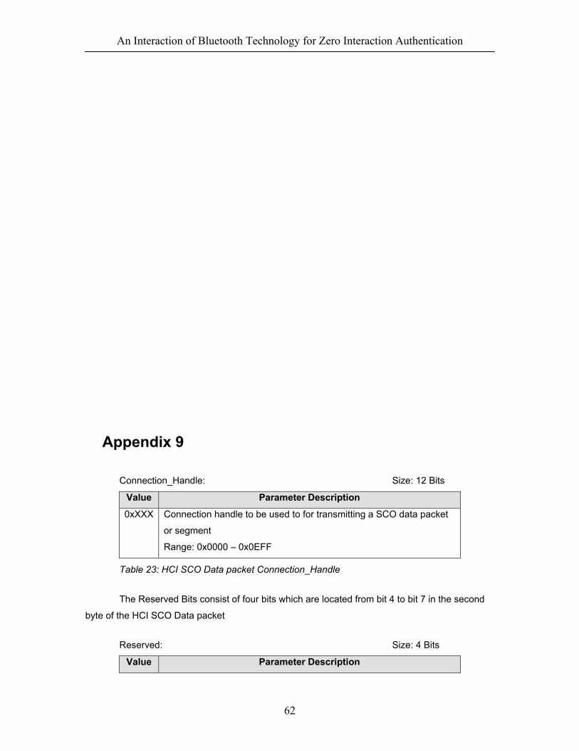
An Interaction of Bluetooth Technology for Zero Interaction Authentication
62
Appendix 9 Connection_Handle: Size: 12 Bits
Value Parameter Description
0xXXX Connection handle to be used to for transmitting a SCO data packet
or segment
Range: 0x0000 – 0x0EFF
Table 23: HCI SCO Data packet Connection_Handle
The Reserved Bits consist of four bits which are located from bit 4 to bit 7 in the second
byte of the HCI SCO Data packet Reserved: Size: 4 Bits
Value Parameter Description

An Interaction of Bluetooth Technology for Zero Interaction Authentication
63
XXXX Reserved for future use
Table 24: HCI SCO Data packet Reserved
Data_Total_Length: Size: 1 Byte
Value Parameter Description
0xXX Length of SCO data measured in bytes
Table 25: HCI SCO Data packet Data_Total_Length
Appendix 10

An Interaction of Bluetooth Technology for Zero Interaction Authentication
64

An Interaction of Bluetooth Technology for Zero Interaction Authentication
65
Table 26: Link Control Commands

An Interaction of Bluetooth Technology for Zero Interaction Authentication
66
Appendix 11
Table 27: Link Policy Commands
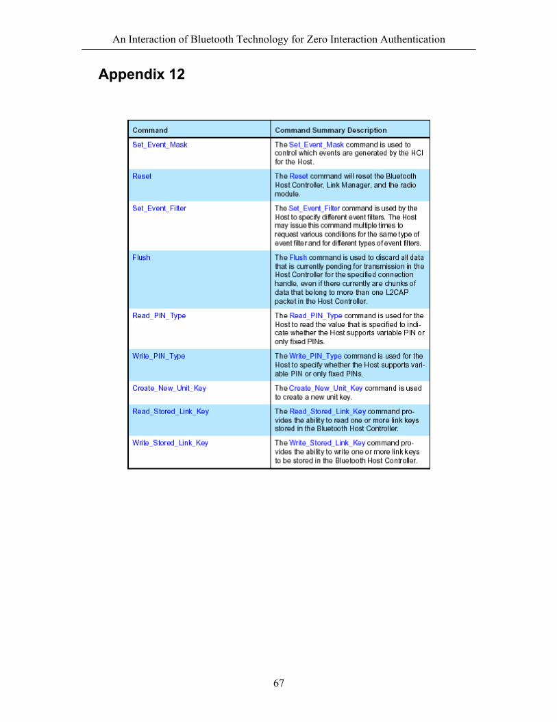
An Interaction of Bluetooth Technology for Zero Interaction Authentication
67
Appendix 12

An Interaction of Bluetooth Technology for Zero Interaction Authentication
68

An Interaction of Bluetooth Technology for Zero Interaction Authentication
69

An Interaction of Bluetooth Technology for Zero Interaction Authentication
70

An Interaction of Bluetooth Technology for Zero Interaction Authentication
71

An Interaction of Bluetooth Technology for Zero Interaction Authentication
72
Table 28: Host Controller & Baseband Commands

An Interaction of Bluetooth Technology for Zero Interaction Authentication
73
Appendix 13
Table 29: Informational Parameters
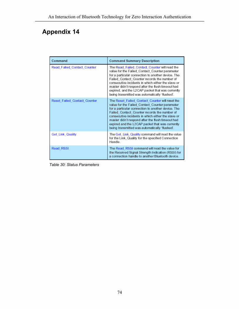
An Interaction of Bluetooth Technology for Zero Interaction Authentication
74
Appendix 14
Table 30: Status Parameters

An Interaction of Bluetooth Technology for Zero Interaction Authentication
75
Appendix 15
Table 31: Testing Commands

An Interaction of Bluetooth Technology for Zero Interaction Authentication
76
Appendix 16

An Interaction of Bluetooth Technology for Zero Interaction Authentication
77

An Interaction of Bluetooth Technology for Zero Interaction Authentication
78
Table 32: Event

An Interaction of Bluetooth Technology for Zero Interaction Authentication
79
Appendix 17 List of Acronyms and Abbreviations
Acronyms of Abbreviations Writing out in full
ACK Acknowledgement ACL Link Asynchronous Connection-Less link AM_ADDR Active Member Address AR_ADDR Access Request Address ARQ Automatic Repeat Request BD_ADDR Bluetooth Device Address CAC Channel Access Code COF Ciphering Offset CRC Cyclic Redundancy check DAC Device Access Code DIAC Dedicated Inquiry Access Code FEC Forward Error Correction Code FH Frequency Hopping FHS Frequency Hop Synchronization GIAC General Inquiry Access Code HCI Host Controller Interface IAC Inquiry Access Code L_CH Logical Channel L2CAP Logical Link Control and Application Protocol LC Link Controller LCP Link Controller Protocol LM Link Manager LMP Link Manager Protocol MSB Most Significant Bit NAK Negative Acknowledgement OBEX Object Exchange Protocol OCF Opcode Command Field PDU Protocol Data Unit PM_ADDR Parked Member Address RF Radio Frequency RFCOMM Serial cable emulation protocol based on ETSI TS 07.10 RX Receiver SCO link Synchronous Connection-Oriented link SDP Service Discovery Protocol SEQN Sequential Numbering Scheme UAP Upper Address Port UART Universal Asynchronous receiver Transmitter UC User Control UIAC Unlimited Inquiry Access Control USB Universal Serial Bus
Table 33: Acronyms and Abbreviations