Embed Size (px)
Citation preview

SCHMIDT OS-120OPERATING INSTRUCTIONS
CONSTRUCTION
made in Switzerlandwww.proceq.com


© 2013 Proceq SA 1
Contents
1. Safety and Liability . . . . . . . . . . . . . . . . . . . . . . . . . . . . . . . . . . . . . .21.1 Safety and Usage Precautions . . . . . . . . . . . . . . . . . . . . . . . . . . . . . . .21.2 Liability. . . . . . . . . . . . . . . . . . . . . . . . . . . . . . . . . . . . . . . . . . . . . . . . . .21.3 Safety Instructions . . . . . . . . . . . . . . . . . . . . . . . . . . . . . . . . . . . . . . . . .21.4 Designated Use . . . . . . . . . . . . . . . . . . . . . . . . . . . . . . . . . . . . . . . . . . .2
2. Instrument Selection . . . . . . . . . . . . . . . . . . . . . . . . . . . . . . . . . . . . .32.1 Schmidt OS-120 Models . . . . . . . . . . . . . . . . . . . . . . . . . . . . . . . . . . . .3
3. Schmidt OS-120 Layout . . . . . . . . . . . . . . . . . . . . . . . . . . . . . . . . . . .3
4. Measuring and Evaluation with the Schmidt OS-120PT. . . . . . . . . .44.1 Functional Check . . . . . . . . . . . . . . . . . . . . . . . . . . . . . . . . . . . . . . . . . .44.2 Preparations. . . . . . . . . . . . . . . . . . . . . . . . . . . . . . . . . . . . . . . . . . . . . .54.3 Measuring . . . . . . . . . . . . . . . . . . . . . . . . . . . . . . . . . . . . . . . . . . . . . . .64.4 Conversion Curves for Schmidt OS-120PT. . . . . . . . . . . . . . . . . . . . . .6
5. Measuring and Evaluation with the Schmidt OS-120PM . . . . . . . . .95.1 Functional Check . . . . . . . . . . . . . . . . . . . . . . . . . . . . . . . . . . . . . . . . . .95.2 Preparations. . . . . . . . . . . . . . . . . . . . . . . . . . . . . . . . . . . . . . . . . . . . . .95.3 Measuring . . . . . . . . . . . . . . . . . . . . . . . . . . . . . . . . . . . . . . . . . . . . . . .95.4 Rating Table for Schmidt OS-120PM. . . . . . . . . . . . . . . . . . . . . . . . . .10
6. Technical data . . . . . . . . . . . . . . . . . . . . . . . . . . . . . . . . . . . . . . . . .10
7. Standards and Guidelines . . . . . . . . . . . . . . . . . . . . . . . . . . . . . . . .117.1 Standards. . . . . . . . . . . . . . . . . . . . . . . . . . . . . . . . . . . . . . . . . . . . . . .117.2 Guidelines . . . . . . . . . . . . . . . . . . . . . . . . . . . . . . . . . . . . . . . . . . . . . .11
8. Part Numbers and Accessories . . . . . . . . . . . . . . . . . . . . . . . . . . . .118.1 Units. . . . . . . . . . . . . . . . . . . . . . . . . . . . . . . . . . . . . . . . . . . . . . . . . . .118.2 Accessories . . . . . . . . . . . . . . . . . . . . . . . . . . . . . . . . . . . . . . . . . . . . .11
9. Maintenance and Support . . . . . . . . . . . . . . . . . . . . . . . . . . . . . . . .129.1 Maintenance . . . . . . . . . . . . . . . . . . . . . . . . . . . . . . . . . . . . . . . . . . . .129.2 Support Concept . . . . . . . . . . . . . . . . . . . . . . . . . . . . . . . . . . . . . . . . .129.3 Standard Warranty and Extended Warranty . . . . . . . . . . . . . . . . . . . .12

2 © 2013 Proceq SA
1. Safety and Liability
1.1 Safety and Usage PrecautionsThis manual contains important information on the safety, use and maintenance of the OS-120PT/PM. Read through the manual carefully before the first use of the instrument. Keep the manual in a safe place for future reference.
1.2 Liability
Our “General Terms and Conditions of Sale and Delivery” apply in all cases. Warranty and liability claims arising from personal injury and damage to property cannot be upheld if they are due to one or more of the following causes:
• Failure to use the instrument in accordance with its designated use as described in this manual.
• Incorrect performance check for operation and maintenance of the instrument and its compo-nents.
• Failure to adhere to the sections of the manual dealing with the performance check, operation and maintenance of the instrument and its components.
• Unauthorized structural modifications to the instrument and its components.
• Serious damage resulting from the effects of foreign bodies, accidents, vandalism and force majeure.
All information contained in this documentation is presented in good faith and believed to be correct. Proceq SA makes no warranties and excludes all liability as to the completeness and/or accuracy of the information.
1.3 Safety InstructionsThe instrument is not allowed to be operated by children or anyone under the influence of alcohol, drugs or pharmaceutical preparations. Anyone who is not familiar with this manual must be super-vised when using the instrument.
1.4 Designated Use
• The instrument is only for its designated purpose as described in these operating instructions.
• Replace faulty components only with original replacement parts from Proceq.
• Accessories should only be installed or connected to the instrument if they are expressly autho-rized by Proceq. If other accessories are installed or connected to the instrument then Proceq will accept no liability and the product guarantee is forfeit.

© 2013 Proceq SA 3
2. Instrument Selection
2.1 Schmidt OS-120 ModelsThere are two models available.
• OS-120PT for testing concrete in the very low compressive strength range. Typically from 1 N/mm2 to 5.0 N/mm2 ( 145 psi – 725 psi). This makes the instrument very suitable for testing fresh concrete to determine the time for formwork removal.
• OS-120PM for testing the mortar joints in brick constructions.
3. Schmidt OS-120 Layout
1 Housing with handle
2 Reset lever
3 Hammer complete (PM/PT)
4 Trigger button
5 Scale (Rebound value)
6 Control knob
7 Hammer head (PM/PT)
A Contact surface
B Loading position
Hammer head Schmidt OS-120PT (7) Hammer head Schmidt OS-120PM (7)

4 © 2013 Proceq SA
4. Measuring and Evaluation with the Schmidt OS-120PT
The OS-120PT is primarily used to measure the early compressive strength of concrete non-destructively. Measurements can also be made on lightweight concrete, plasterboard and similar products.
NOTE! At all times ensure that all your body parts are kept away from the space between the hammer head (7) and the contact surface A.
4.1 Functional CheckA test anvil is necessary for the functional check of the rebound hammer (see chapter 8.2).
Checking the Schmidt OS-120PT on the test anvil
The functional check should ideally be performed before and after each usage of the hammer. As a minimum it should be carried out after 1’000 impacts or once every three months.
• Insure that the control knob (6) is set at the position H. If not proceed with steps 1 to 6 as de-scribed in Chapter 4.2.
• Place the test anvil on a hard, smooth surface (e.g. stone floor).
• Clean the contact surfaces of the anvil and the hammer head.
• Carry out a few impacts on the anvil.
• Perform 10 test impacts on the test anvil.
NOTE! The mean of the rebound values must lie within the tolerance given on the anvil. If this is not the case, e.g following an impact, the hammer mass is not held at the maxi-mum rebound position, then the brake strip must be cleaned.
(typically)
Accuracy of rebound values: For OS-120 PT 176 ± 3
For OS-120 PM 186 ± 3

© 2013 Proceq SA 5
• Clean the brake strip on the under side of the semi-circular housing (1) using a clean cloth soaked in Acetone. When cleaning with Acetone the paint close to the brake surface may be affected. Alternatively, methylated spirit that does not damage the paint can be used.
• Repeat the functional check.
If the mean value is still out of tolerance, the instrument must be taken to an authorized service centre for re-calibration.
4.2 PreparationsIf necessary, use the grinding stone to remove cement residues from the test surface.
Hammer (3) at position 75
• The control knob (6) must be at the desired position V (for testing on vertical surfaces) or H (for testing on horizontal surfaces).
If this is not the case proceed as follows:
1. Place the OS-120 on a flat surface with the scale up and the hammer (3) at loading position B as shown in the first picture of chapter 3.
2. Release the hammer (3) by pushing the reset lever (2) in a downwards direction, keep holding.3. Press, hold down and release the trigger button (4) to move the entire hammer (3) to the posi-
tion 75 on the scale (5).4. Push reset lever (2) down to hold the hammer (3) in place.5. Turn the control knob (6) to position V for testing on a vertical surface, respectively to H for
testing on a horizontal surface.6. Push hammer (3) back to position B. It will click into loading position.
NOTE! The hammer (3) MUST be set to position 75 to enable you to select V or H with the control knob (6).
6 © 2013 Proceq SA
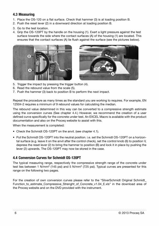
4.3 Measuring1. Place the OS-120 on a flat surface. Check that hammer (3) is at loading position B.2. Push the reset lever (2) in a downward direction at loading position B.
3. Go to the test location.4. Grip the OS-120PT by the handle on the housing (1). Exert a light pressure against the test
surface towards the side where the contact surfaces (A) of the housing (1) are located. This ensures that the contact surfaces (A) lie flush against the surface (see the pictures below).
B
AA
B
5. Trigger the impact by pressing the trigger button (4).6. Read the rebound value from the scale (5).7. Push the hammer (3) back to position B to perform the next impact.
Repeat the procedure as many times as the standard you are working to requires. For example, EN 12504-2 requires a minimum of 9 rebound values for calculating the median.
The rebound value determined in this way can be converted to a compressive strength estimate using the conversion curves (See chapter 4.4.) However, we recommend the creation of a user defined curve specifically for the concrete under test. An EXCEL Macro is available with the product documentation and also on the Proceq website to assist with this.
When the measurement is completed:
• Check the Schmidt OS-120PT on the anvil. (see chapter 4.1).
• Put the Schmidt OS-120PT into the neutral position. i.e. set the Schmidt OS-120PT on a horizon-tal surface (e.g. leave it on the anvil after the control check), set the control knob (6) to position V, depress the reset lever (2) to bring the hammer to position (B) and lock it in place by pushing the lever (2) upwards. The OS-120PT may now be stored in the case.
4.4 Conversion Curves for Schmidt OS-120PTThe typical measuring range, respectively the compressive strength range of the concrete under test lies between 1 N/mm2 (145 psi) and 5 N/mm2 (725 psi). Typical curves are presented for this range on the following two pages.
For the creation of own conversion curves please refer to the “SilverSchmidt Original Schmidt_Function_to_estimate_Compressive_Strenght_of_Concrete_v1.04_E.xls” in the download area of the Proceq website and on the DVD provided with the instrument.

© 2013 Proceq SA 7
0.00
1.00
2.00
3.00
4.00
5.00
6.00
0 5 10 15 20 25 30 35 40 45 50
OS-120 PT Conversion Curve Cube 150/150/150Horizontal impct direction N/mm2 y = 1.05 * (0.0015x2 + 0.0615x - 0.3585) Vertical impact direction N/mm2 y = 1.05 * (0.0009x2 + 0.0808x - 0.5081))
fc C
ube
150/
150/
150
fc [N/mm2 ]
R
0.00
0.50
1.00
1.50
2.00
2.50
3.00
3.50
4.00
4.50
0 5 10 15 20 25 30 35 40 45 50
OS-120 PT Conversion Curve Cylinder 150/300Horizontal impact direction N/mm2 y = 0.8337 * (0.0015x2 + 0.0615x - 0.3585) Vertical impact direction N/mm2 y = 0.8337 * (0.0009x2 + 0.0808x - 0.5081)
fc C
ylin
der
150
/300
fc [N/mm2 ]
R

8 © 2013 Proceq SA
0
100
200
300
400
500
600
700
800
900
0 5 10 15 20 25 30 35 40 45 50
OS-120 PT Conversion Curve Cube 150/150/150Horizontal impact direction psi y = 152.2899 * (0.0015x2 + 0.0615x - 0.3585) Vertical impact direction psi y = 152.2899 * (0.0009x2 + 0.0808x - 0.5081)
fc C
ube
150
/150
/150
fc [psi]
R
0
100
200
300
400
500
600
700
0 5 10 15 20 25 30 35 40 45 50
OS-120 PT Conversion Curve Cylinder 150/300Horizontal impact direction psi y = 0.8337 * 145.038 * (0.0015x2 + 0.0615x - 0.3585) Vertical impact direction psi y = 0.8337 * 145.038 * (0.0009x2 + 0.0808x - 0.5081)
fc C
ylin
der
150
/300
fc [psi]
R

© 2013 Proceq SA 9
A form factor must be used to correct the conversion estimate in cases where the compressive strength is not to be used as either as standard cube compressive strength (150/150/150 cube) or a standard cylinder compressive strength (150/300 cylinder). (See the corresponding information in the document delivered with the instrument, or on the Proceq website.)
5. Measuring and Evaluation with the Schmidt OS-120PM
The OS-120PM is used to test the mortar of joints in masonry constructions non-destructively. The mortar can then be classified based on the rebound value. The classification is only valid for mea-surements on vertical walls.
For a detailed description of the procedures of the following three chapters 5.1, 5.2 and 5.3 refer to the chapters 4.1, 4.2 and 4.3.
NOTE! At all times ensure that all your body parts are kept away from the space between the hammer head (7) and the contact surface A.
5.1 Functional CheckThe functional check of the Schmidt OS-120PM is carried out in the same way as for the Schmidt
OS-102PT (see chapter 4.1).
5.2 Preparations
• Identify a suitable location on the mortar joint. If necessary, remove any dirt or moss, etc.
• The hammer (3) must be fixed at position 75 on the scale (5) and the control knob (6) turned to position V (for testing on vertical surfaces). See respective picture in chapter 4.2.
5.3 Measuring
• Grip the Schmidt OS-120PM by the handle on the housing (1). Exert a light pressure against the test surface towards the side where the contact surfaces (A) of the housing (1) are located. This ensures that the contact surfaces (A) lie flush against the surface. Additionally make certain that the joint to be tested is precisely in the middle of the circular opening of the housing (1) in position A. This will ensure that the hammer head (7) impacts on the surface of the joint. (See the picture below.)
• Using the reset lever (2), bring the hammer (3) to position B.
A
B

10 © 2013 Proceq SA
• Trigger the impact by pressing the trigger button (4).
• Read the rebound value from the scale (5).
Repeat the procedure as many times as the standard you are working to requires. For example, EN 12504-2 requires a minimum of 9 rebound values for calculating the median.
The rebound value determined in this way can be used to give a classification by means of the evaluation table. (See chapter 5.4).
When the measurement is completed:
• Check the Schmidt OS-120PM on the anvil (see chapter 4.1)
• Put the Schmidt OS-120PM into the neutral position. i.e. set the OS-120PM on a horizontal surface (e.g. leave it on the anvil after the control check), set the control knob (6) to position V, depress the reset lever (2) to bring the hammer (3) to position (B) and lock it in place by pushing the lever (2) upwards. The Schmidt OS-120PM may now be stored in the case.
5.4 Rating Table for Schmidt OS-120PMThe mortar joints can be classified using the rating table below.
C
lass
ifica
tion
Excellent
Very good
Good
Reasonable
Average
Poor
10 20 30 40 50 60 70 80 90 100
Rebound value R
The customer is free to create his own mortar specific rating table.
6. Technical dataSchmidt OS-120PT Schmidt OS-120PM
Measuring range See chapter 4.4 See chapter 5.4
Impact energy 0.833 Nm (0.614 ft lbf)
Accuracy (of rebound value on anvil) typically 176 ± 3 typically 186 ± 3
Hammer mass 720 g (1.59 lb) 665 g (1.47 lb)
Hammer head diameter 40 mm (1.57“) 8.0 mm (0.315“)
Weight 3.45 kg (7.60 lb)
Dimensions of housing 230 x 60 x 200 mm (9.06“ x 2.36“ x 7.87“)
Operating temperature -10 bis 50°C (14 bis 122°F)
Storage temperature -10 bis 70°C (14 bis 158°F)

© 2013 Proceq SA 11
7. Standards and Guidelines
7.1 StandardsThe rebound number is determined on the basis of the following standards: EN12504-2 (Europe), ASTM C 805 (North America), JGJ/T 23-2011 (China). Applies to Schmidt OS-120PT only.
For the creation of user defined conversion curves, we recommend the procedures described in EN 13791 (Europe), ASTM C805, ACI 228.1R (North America), JGJ T23-2011 (China), see chapter 4.4. Applies to Schmidt OS-120PT only.
7.2 GuidelinesAustrian Guideline for tunnel lining, published December 2012. Austrian Construction Association. (To determine the time for formwork removal during tunnel construction). Applies to Schmidt OS-120PT.
TNO Report BI -88-009/61.8.2060-VOE from IBBC Delft Netherlands (Mortar joint testing). Applies to Schmidt OS-120PM.
8. Part Numbers and Accessories
8.1 Units
PART NUMBER DESCRIPTION
310 06 001 OS-120PT Concrete test hammer including, operating instructions, certificate of conformity, CD with documentation, grinding stone and car-rying case
310 06 002 OS-120PM Mortar test hammer including opera-ting instructions, certificate of conformity, CD with documentation and carrying case

12 © 2013 Proceq SA
8.2 Accessories
PART NUMBER DESCRIPTION
310 99 037 Grinding stone (only required for OS-120-PT)
310 06 058 Carrying case
310 10 000 Test anvil
9. Maintenance and Support
9.1 MaintenanceMaintenance includes a regular check of the instrument and cleaning of the breaking strip as de-scribed in chapter 4.1.
To guarantee consistent, reliable and accurate measurements, the instrument should be calibrated on a yearly basis. The customer may however, determine the service interval based on his own experience and usage.
Normal use may result in smaller damages to the paint, for example, inside of the housing (1) at the loading position (B) caused by the hammer (3). This will neither impair the functioning nor the life span of the Schmidt OS-120.
9.2 Support ConceptProceq is committed to providing a complete support service for this instrument by means of our global service and support facilities. It is recommended that the user register the product on www.proceq.com to obtain the latest on available updates and other valuable information.
9.3 Standard Warranty and Extended WarrantyThe standard warranty covers the mechanical portion of the instrument for 6 months.

© 2013 Proceq SA 13
Notes

14 © 2013 Proceq SA
Proceq EuropaRingstrasse 2CH-8603 SchwerzenbachTelefon +41-43-355 38 00Fax +41-43-355 38 [email protected]
Proceq UK Ltd.Bedford i-lab, Priory Business ParkStannard WayBedford MK44 3RZVereinigtes KönigreichTelefon [email protected]
Proceq USA, Inc.117 Corporation DriveAliquippa, PA 15001Telefon +1-724-512-0330Fax [email protected]
Proceq Asia Pte Ltd12 New Industrial Road#02-02A Morningstar CentreSingapur 536202Telefon +65-6382-3966Fax [email protected]
Proceq Rus LLCUl. Optikov 4Korp. 2, Lit. A, Office 412197374 St. PetersburgRusslandTelefon/Fax + 7 812 448 35 00 [email protected]
Proceq Middle EastP. O. Box 8365, SAIF Zone,Sharjah, Vereinigte Arabische EmirateTelefon +971-6-557-8505Fax [email protected]
Proceq SAO Ltd.South American OperationsAlameda Jaú, 1905, cj 54Jardim Paulista, São Paulo Brasilien Cep. 01420-007 Telefon +55 11 3083 38 [email protected]
Proceq ChinaUnit B, 19th FloorFive Continent International Mansion, No. 807Zhao Jia Bang RoadShanghai 200032Telefon +86 21-63177479Fax +86 21 [email protected]
Subject to change. Copyright © 2013 by Proceq SA, Schwerzenbach. All rights reserved.
Part Number: 820 310 02E ver 10 2013