Embed Size (px)
Citation preview
50
Schlaucharmaturen Hose couplings Armaduras para tubos
50.2Nippel mit Rohrstutzen, geradeNipples with pipe connector, straightBoquillas lisas rectas
EBEL/EBES
50.3-50.4Nippel mit Rohrstutzen, 45°/90°Nipples with pipe connector, 45°/90°Boquillas lisas a 45°/90°
EBEL/EBES 45°/90°
50.5Nippel mit Universal-Dichtkegel, geradeNipples with universal taper, straightBoquillas con junta cónica universal rectas
EDKL
50.6-50.7Nippel mit Universal-Dichtkegel, 45°/90°Nipples with universal taper, 45°/90°Boquillas con junta cónica universal a 45°/90°
EDKL 45°/90°
50.8Nippel mit Dichtkegel, geradeNipples with taper, straightBoquillas con junta cónica rectas
EDKR
50.9-50.10Nippel mit Dichtkegel, 45°/90°Nipples with taper, 45°/90°Boquillas con junta cónica a 45°/90°
EDKR 45°/90°
50.11Nippel mit Dichtkegel und O-Ring, geradeNipples with taper and O-ring, straightBoquillas con junta cónica y junta tórica rectas
EDKOL/EDKOS
50.12-50.13Nippel mit Dichtkegel und O-Ring, 45°/90°Nipples with taper and O-ring, 45°/90°Boquillas con junta cónica y junta tórica a 45°/90°
EDKOL/EDKOS 45°/90°
50.14-50.15Außengewinde-Nippel, 24° KonusMale adaptor nipples, 24° taperBoquillas roscadas, cono de 24°
ECEL/ECES
50.16Außengewinde-Nippel, 60° KonusMale adaptor nipples, 60° taperBoquillas roscadas, cono de 60°
EAGR
50.17Außengewinde-Nippel BSPPMale adaptor nipples BSPPBoquillas roscadas BSPP
EAGF
50.18Außengewinde-Nippel BSPTMale adaptor nipples BSPTBoquillas roscadas BSPT
EAGK
50.19Außengewinde-Nippel NPTMale adaptor nipples NPTBoquillas roscadas NPT
EAGN
50.20Außengewinde-Nippel NPTFMale adaptor nipples NPTFBoquillas roscadas NPTF
EAGNF
50.21Außengewinde-Nippel, 74° JIC KonusMale adaptor nipples, 74° JIC taperBoquillas roscadas, cono de 74° JIC
EAGJ
50.22Außengewinde-Nippel, 74° JIC, geradeMale adaptor nipples, 74° JIC, straightBoquillas roscadas, de 74° JIC rectas
EDKJ
50.23-50.24Außengewinde-Nippel, 74° JIC, 45°/90°Male adaptor nipples, 74° JIC, 45°/90°Boquillas roscadas, de 74° JIC a 45°/90°
EDKJ 45°/90°
50.25Gerade AdapterStraight adaptorsAdaptadores rectos
EA
50.26Gerade ReduzieradapterStraight reducing adaptorsAdaptadores de reducción rectos
EAR
50.27-50.28Schnellverschluss-KupplungenQuick couplingsAcoplamientos de cierre rápido
EKM-EKS
50.29-50.30PressfassungenFerrulesCasquillo para prensar
EF
50.31Schlauch-AdapterHose adaptorsAdaptadores para tubos flexibles
ESA
50.32Schlauch-ÜberwurfmutternHose nutsTuercas de unión para tubos flexibles
SÜM
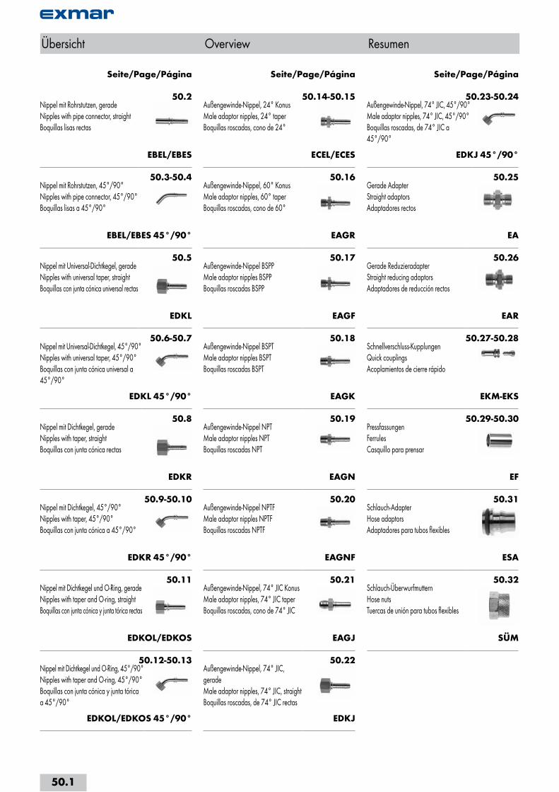
Seite/Page/Página Seite/Page/Página Seite/Page/Página
Übersicht Overview Resumen
50.1
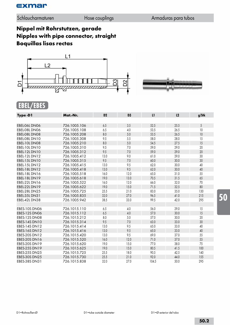
Nippel mit Rohrstutzen, geradeNipples with pipe connector, straightBoquillas lisas rectas
EBEL/EBESType -D1 Mat.-Nr. D2 D3 L1 L2 g/Stk EBEL-06L DN06 726.1005.106 6.5 3.5 52.5 25.5 5EBEL-08L DN06 726.1005.108 6.5 4.0 53.5 26.5 10EBEL-08L DN08 726.1005.208 8.0 5.0 53.5 26.5 10EBEL-08L DN10 726.1005.308 9.5 5.5 58.0 28.0 15EBEL-10L DN08 726.1005.210 8.0 5.0 54.5 27.5 15EBEL-10L DN10 726.1005.310 9.5 7.0 59.0 29.0 20EBEL-12L DN10 726.1005.312 9.5 7.0 59.0 29.0 20EBEL-12L DN12 726.1005.412 13.0 9.0 61.0 29.0 30EBEL-15L DN10 726.1005.315 9.5 7.0 60.0 30.0 30EBEL-15L DN12 726.1005.415 13.0 9.5 62.0 30.0 40EBEL-18L DN12 726.1005.418 13.0 9.5 62.0 30.0 40EBEL-18L DN16 726.1005.518 16.0 12.0 65.0 31.0 55EBEL-18L DN19 726.1005.618 19.0 13.0 70.5 31.5 65EBEL-22L DN16 726.1005.522 16.0 12.0 66.0 32.0 70EBEL-22L DN19 726.1005.622 19.0 15.0 71.5 32.5 80EBEL-28L DN25 726.1005.725 25.5 21.0 83.0 35.0 130EBEL-35L DN31 726.1005.835 32.0 27.0 96.5 41.0 215EBEL-42L DN38 726.1005.942 38.5 33.0 99.5 42.0 295 EBES-10S DN06 726.1015.110 6.5 4.0 56.0 29.0 15EBES-12S DN06 726.1015.112 6.5 4.0 57.0 30.0 15EBES-12S DN08 726.1015.212 8.0 5.0 57.0 30.0 20EBES-14S DN10 726.1015.314 9.5 7.0 63.0 33.0 30EBES-14S DN12 726.1015.414 13.0 9.5 65.0 33.0 40EBES-16S DN12 726.1015.416 13.0 9.5 65.0 33.0 40EBES-20S DN12 726.1015.420 13.0 9.5 69.0 37.0 55EBES-20S DN16 726.1015.520 16.0 12.0 71.0 37.0 55EBES-20S DN19 726.1015.620 19.0 15.0 77.0 38.0 75EBES-25S DN19 726.1015.625 19.0 15.0 80.5 41.5 100EBES-25S DN25 726.1015.725 25.5 18.0 90.5 42.5 140EBES-30S DN25 726.1015.730 25.5 21.0 92.0 44.0 155EBES-38S DN31 726.1015.838 32.0 27.0 104.5 50.0 295
Schlaucharmaturen Hose couplings Armaduras para tubos
D1=Rohraußen-Ø D1=tube outside diameter D1=Ø exterior del tubo
50.2
i
s
10
20
30
40
50
60
70
80
a
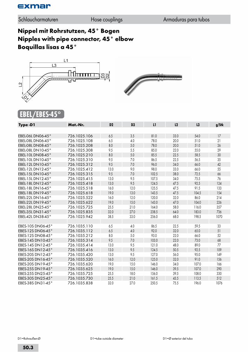
Nippel mit Rohrstutzen, 45° BogenNipples with pipe connector, 45° elbowBoquillas lisas a 45°
EBEL/EBES-45°Type -D1 Mat.-Nr. D2 D3 L1 L2 L3 g/Stk EBEL-06L DN06-45° 726.1025.106 6.5 3.5 81.0 33.0 54.0 17EBEL-08L DN06-45° 726.1025.108 6.5 4.0 78.0 20.0 51.0 21EBEL-08L DN08-45° 726.1025.208 8.0 5.0 78.0 20.0 51.0 26EBEL-08L DN10-45° 726.1025.308 9.5 5.5 85.0 22.0 55.0 29EBEL-10L DN08-45° 726.1025.210 8.0 5.0 85.5 22.5 58.5 30EBEL-10L DN10-45° 726.1025.310 9.5 7.0 86.5 22.5 56.5 35EBEL-12L DN10-45° 726.1025.312 9.5 7.0 96.0 34.0 66.0 42EBEL-12L DN12-45° 726.1025.412 13.0 9.0 98.0 33.0 66.0 55EBEL-15L DN10-45° 726.1025.315 9.5 7.0 102.5 38.0 72.5 66EBEL-15L DN12-45° 726.1025.415 13.0 9.5 107.5 34.0 75.5 76EBEL-18L DN12-45° 726.1025.418 13.0 9.5 124.5 47.5 92.5 124EBEL-18L DN16-45° 726.1025.518 16.0 12.0 125.5 47.5 91.5 133EBEL-18L DN19-45° 726.1025.618 19.0 13.0 143.5 47.5 104.5 154EBEL-22L DN16-45° 726.1025.522 16.0 12.0 120.0 32.0 86.0 214EBEL-22L DN19-45° 726.1025.622 19.0 15.0 143.0 47.0 104.0 226EBEL-28L DN25-45° 726.1025.725 25.5 21.0 164.0 58.0 116.0 357EBEL-35L DN31-45° 726.1025.835 32.0 27.0 238.5 64.0 183.0 736EBEL-42L DN38-45° 726.1025.942 38.5 33.0 256.0 68.0 198.5 1070 EBES-10S DN06-45° 726.1035.110 6.5 4.0 86.5 22.5 59.5 33EBES-12S DN06-45° 726.1035.112 6.5 4.0 92.0 32.0 65.0 51EBES-12S DN08-45° 726.1035.212 8.0 5.0 93.0 22.0 66.0 52EBES-14S DN10-45° 726.1035.314 9.5 7.0 103.0 22.0 73.0 68EBES-14S DN12-45° 726.1035.414 13.0 9.5 121.0 48.0 89.0 77EBES-16S DN12-45° 726.1035.416 13.0 9.5 124.5 50.5 92.5 109EBES-20S DN12-45° 726.1035.420 13.0 9.5 127.0 56.0 95.0 149EBES-20S DN16-45° 726.1035.520 16.0 12.0 125.0 32.0 91.0 156EBES-20S DN19-45° 726.1035.620 19.0 15.0 146.0 34.0 107.0 166EBES-25S DN19-45° 726.1035.625 19.0 15.0 146.0 39.5 107.0 290EBES-25S DN25-45° 726.1035.725 25.5 18.0 156.0 39.5 108.0 330EBES-30S DN25-45° 726.1035.730 25.5 21.0 161.5 43.5 113.5 512EBES-38S DN31-45° 726.1035.838 32.0 27.0 250.5 75.5 196.0 1076
Schlaucharmaturen Hose couplings Armaduras para tubos
D1=Rohraußen-Ø D1=tube outside diameter D1=Ø exterior del tubo
50.3
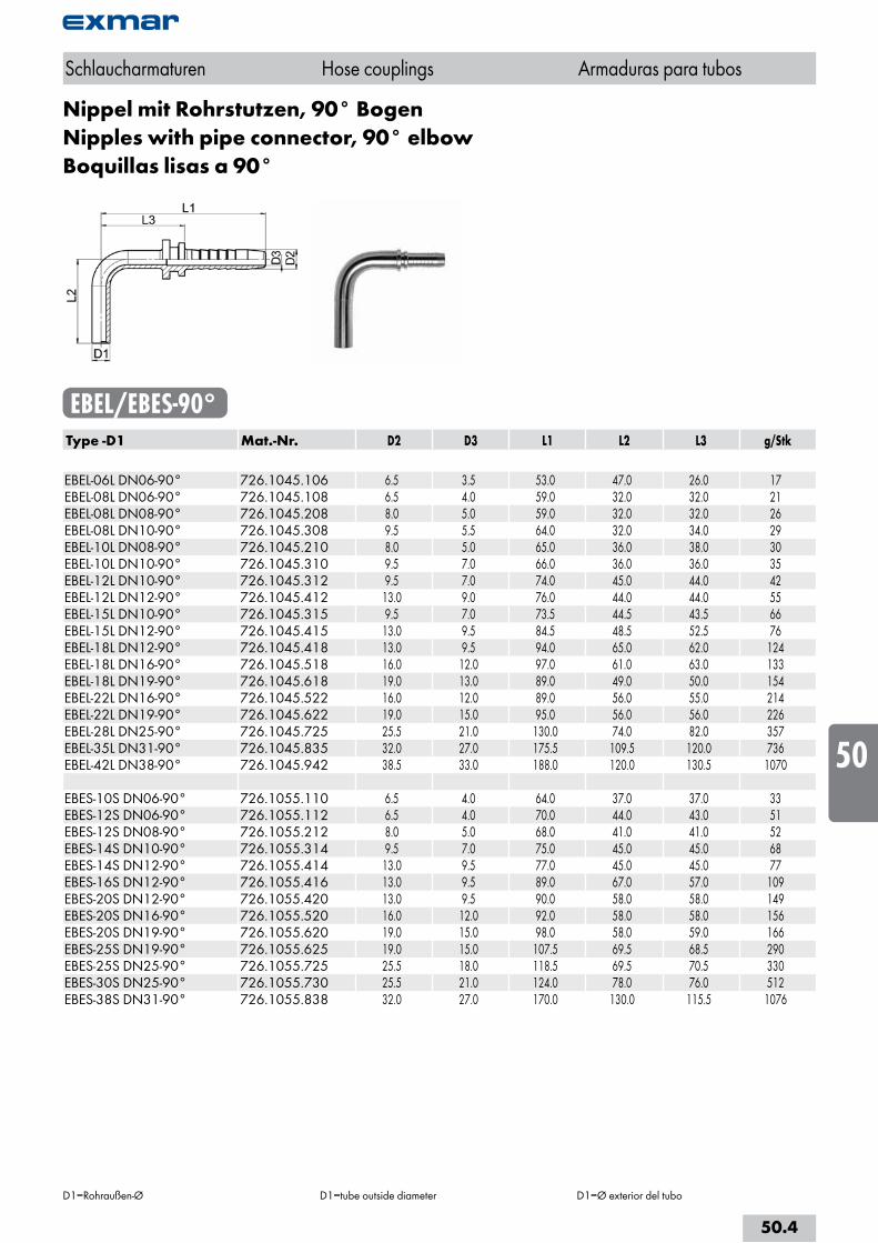
Nippel mit Rohrstutzen, 90° BogenNipples with pipe connector, 90° elbowBoquillas lisas a 90°
EBEL/EBES-90°Type -D1 Mat.-Nr. D2 D3 L1 L2 L3 g/Stk EBEL-06L DN06-90° 726.1045.106 6.5 3.5 53.0 47.0 26.0 17EBEL-08L DN06-90° 726.1045.108 6.5 4.0 59.0 32.0 32.0 21EBEL-08L DN08-90° 726.1045.208 8.0 5.0 59.0 32.0 32.0 26EBEL-08L DN10-90° 726.1045.308 9.5 5.5 64.0 32.0 34.0 29EBEL-10L DN08-90° 726.1045.210 8.0 5.0 65.0 36.0 38.0 30EBEL-10L DN10-90° 726.1045.310 9.5 7.0 66.0 36.0 36.0 35EBEL-12L DN10-90° 726.1045.312 9.5 7.0 74.0 45.0 44.0 42EBEL-12L DN12-90° 726.1045.412 13.0 9.0 76.0 44.0 44.0 55EBEL-15L DN10-90° 726.1045.315 9.5 7.0 73.5 44.5 43.5 66EBEL-15L DN12-90° 726.1045.415 13.0 9.5 84.5 48.5 52.5 76EBEL-18L DN12-90° 726.1045.418 13.0 9.5 94.0 65.0 62.0 124EBEL-18L DN16-90° 726.1045.518 16.0 12.0 97.0 61.0 63.0 133EBEL-18L DN19-90° 726.1045.618 19.0 13.0 89.0 49.0 50.0 154EBEL-22L DN16-90° 726.1045.522 16.0 12.0 89.0 56.0 55.0 214EBEL-22L DN19-90° 726.1045.622 19.0 15.0 95.0 56.0 56.0 226EBEL-28L DN25-90° 726.1045.725 25.5 21.0 130.0 74.0 82.0 357EBEL-35L DN31-90° 726.1045.835 32.0 27.0 175.5 109.5 120.0 736EBEL-42L DN38-90° 726.1045.942 38.5 33.0 188.0 120.0 130.5 1070 EBES-10S DN06-90° 726.1055.110 6.5 4.0 64.0 37.0 37.0 33EBES-12S DN06-90° 726.1055.112 6.5 4.0 70.0 44.0 43.0 51EBES-12S DN08-90° 726.1055.212 8.0 5.0 68.0 41.0 41.0 52EBES-14S DN10-90° 726.1055.314 9.5 7.0 75.0 45.0 45.0 68EBES-14S DN12-90° 726.1055.414 13.0 9.5 77.0 45.0 45.0 77EBES-16S DN12-90° 726.1055.416 13.0 9.5 89.0 67.0 57.0 109EBES-20S DN12-90° 726.1055.420 13.0 9.5 90.0 58.0 58.0 149EBES-20S DN16-90° 726.1055.520 16.0 12.0 92.0 58.0 58.0 156EBES-20S DN19-90° 726.1055.620 19.0 15.0 98.0 58.0 59.0 166EBES-25S DN19-90° 726.1055.625 19.0 15.0 107.5 69.5 68.5 290EBES-25S DN25-90° 726.1055.725 25.5 18.0 118.5 69.5 70.5 330EBES-30S DN25-90° 726.1055.730 25.5 21.0 124.0 78.0 76.0 512EBES-38S DN31-90° 726.1055.838 32.0 27.0 170.0 130.0 115.5 1076
Schlaucharmaturen Hose couplings Armaduras para tubos
D1=Rohraußen-Ø D1=tube outside diameter D1=Ø exterior del tubo
50.4
i
s
10
20
30
40
50
60
70
80
a
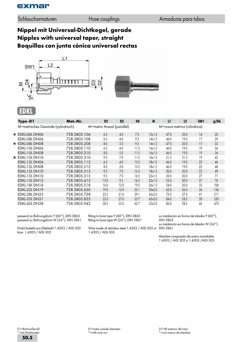
Nippel mit Universal-Dichtkegel, geradeNipples with universal taper, straightBoquillas con junta cónica universal rectas
EDKLType -D1 Mat.-Nr. D2 D3 D4 M L1 L2 SW1 g/StkM=metrisches Gewinde (zylindrisch) M=metric thread (parallel) M=rosca métrica (cilindrica)
EDKL-06L DN06 728.3805.106 6.5 4.0 7.3 12x1.5 47.0 20.0 14 20 EDKL-08L DN06 728.3805.108 6.5 4.0 9.3 14x1.5 46.0 19.0 17 29
EDKL-08L DN08 728.3805.208 8.0 5.0 9.3 14x1.5 47.0 20.0 17 32 EDKL-10L DN06 728.3805.110 6.5 4.0 11.5 16x1.5 46.0 19.0 19 34 EDKL-10L DN08 728.3805.210 8.0 5.0 11.5 16x1.5 46.0 19.0 19 36
EDKL-10L DN10 728.3805.310 9.5 7.0 11.5 16x1.5 51.5 21.5 19 42 EDKL-12L DN06 728.3805.112 6.5 4.0 13.5 18x1.5 46.0 19.0 22 46 EDKL-12L DN08 728.3805.212 8.0 5.0 13.5 18x1.5 46.0 19.0 22 48 EDKL-12L DN10 728.3805.312 9.5 7.0 13.5 18x1.5 50.0 20.0 22 49 EDKL-15L DN10 728.3805.315 9.5 7.0 16.5 22x1.5 50.0 20.0 27 71 EDKL-15L DN12 728.3805.415 13.0 9.5 16.5 22x1.5 52.0 20.0 27 76 EDKL-18L DN16 728.3805.518 16.0 12.0 19.5 26x1.5 54.0 20.0 32 106 EDKL-22L DN19 728.3805.620 19.0 15.0 23.1 30x2.0 65.0 26.0 36 156 EDKL-28L DN25 728.3805.728 25.5 21.0 29.1 36x2.0 75.0 27.0 41 211 EDKL-35L DN31 728.3805.835 32.0 27.0 35.7 45x2.0 84.0 28.5 50 330 EDKL-42L DN38 728.3805.942 38.5 33.0 42.7 52x2.0 86.0 28.5 60 470
passend zu Bohrungsform Y (60°), DIN 3863passend zu Bohrungsform W (24°), DIN 3861
Draht besteht aus Edelstahl 1.4303 / AISI 305 bzw. 1.4305 / AISI 303
fitting to bore type Y (60°), DIN 3863fitting to bore type W (24°), DIN 3861
Wire made of stainless steel 1.4303 / AISI 305 or 1.4305 / AISI 303
su instalación en forma de taladro Y (60°), DIN 3863su instalación en forma de taladro W (24°), DIN 3861
Alambre compuesto de acero inoxidable 1.4303 / AISI 305 o 1.4305 /AISI 303
Schlaucharmaturen Hose couplings Armaduras para tubos
D1=Rohraußen-Ø*=mit Drahtmutter
D1=tube outside diameter*=with wire nut
D1=Ø exterior del tubo*=con tuerca de alambre
50.5
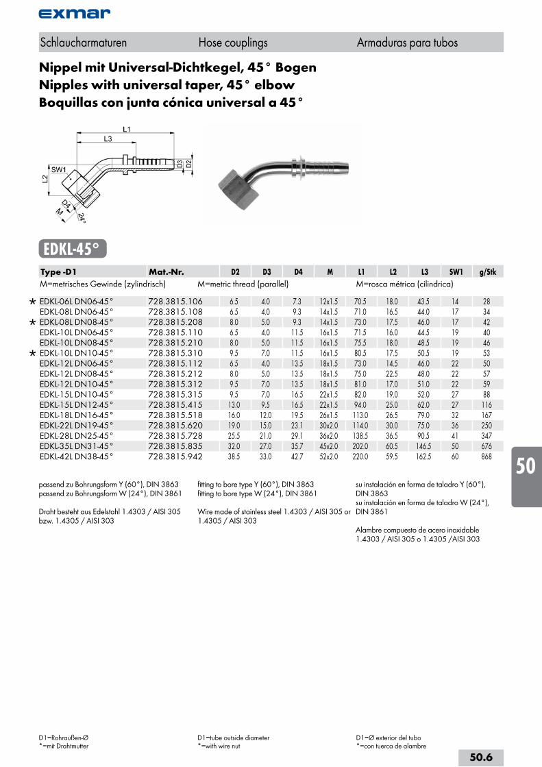
Nippel mit Universal-Dichtkegel, 45° BogenNipples with universal taper, 45° elbowBoquillas con junta cónica universal a 45°
EDKL-45°Type -D1 Mat.-Nr. D2 D3 D4 M L1 L2 L3 SW1 g/StkM=metrisches Gewinde (zylindrisch) M=metric thread (parallel) M=rosca métrica (cilindrica)
EDKL-06L DN06-45° 728.3815.106 6.5 4.0 7.3 12x1.5 70.5 18.0 43.5 14 28 EDKL-08L DN06-45° 728.3815.108 6.5 4.0 9.3 14x1.5 71.0 16.5 44.0 17 34
EDKL-08L DN08-45° 728.3815.208 8.0 5.0 9.3 14x1.5 73.0 17.5 46.0 17 42 EDKL-10L DN06-45° 728.3815.110 6.5 4.0 11.5 16x1.5 71.5 16.0 44.5 19 40 EDKL-10L DN08-45° 728.3815.210 8.0 5.0 11.5 16x1.5 75.5 18.0 48.5 19 46
EDKL-10L DN10-45° 728.3815.310 9.5 7.0 11.5 16x1.5 80.5 17.5 50.5 19 53 EDKL-12L DN06-45° 728.3815.112 6.5 4.0 13.5 18x1.5 73.0 14.5 46.0 22 50 EDKL-12L DN08-45° 728.3815.212 8.0 5.0 13.5 18x1.5 75.0 22.5 48.0 22 57 EDKL-12L DN10-45° 728.3815.312 9.5 7.0 13.5 18x1.5 81.0 17.0 51.0 22 59 EDKL-15L DN10-45° 728.3815.315 9.5 7.0 16.5 22x1.5 82.0 19.0 52.0 27 88 EDKL-15L DN12-45° 728.3815.415 13.0 9.5 16.5 22x1.5 94.0 25.0 62.0 27 116 EDKL-18L DN16-45° 728.3815.518 16.0 12.0 19.5 26x1.5 113.0 26.5 79.0 32 167 EDKL-22L DN19-45° 728.3815.620 19.0 15.0 23.1 30x2.0 114.0 30.0 75.0 36 250 EDKL-28L DN25-45° 728.3815.728 25.5 21.0 29.1 36x2.0 138.5 36.5 90.5 41 347 EDKL-35L DN31-45° 728.3815.835 32.0 27.0 35.7 45x2.0 202.0 60.5 146.5 50 676 EDKL-42L DN38-45° 728.3815.942 38.5 33.0 42.7 52x2.0 220.0 59.5 162.5 60 868
passend zu Bohrungsform Y (60°), DIN 3863passend zu Bohrungsform W (24°), DIN 3861
Draht besteht aus Edelstahl 1.4303 / AISI 305 bzw. 1.4305 / AISI 303
fitting to bore type Y (60°), DIN 3863fitting to bore type W (24°), DIN 3861
Wire made of stainless steel 1.4303 / AISI 305 or 1.4305 / AISI 303
su instalación en forma de taladro Y (60°), DIN 3863 su instalación en forma de taladro W (24°), DIN 3861
Alambre compuesto de acero inoxidable 1.4303 / AISI 305 o 1.4305 /AISI 303
Schlaucharmaturen Hose couplings Armaduras para tubos
D1=Rohraußen-Ø*=mit Drahtmutter
D1=tube outside diameter*=with wire nut
D1=Ø exterior del tubo*=con tuerca de alambre
50.6
i
s
10
20
30
40
50
60
70
80
a
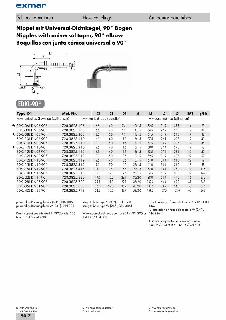
Nippel mit Universal-Dichtkegel, 90° BogenNipples with universal taper, 90° elbowBoquillas con junta cónica universal a 90°
EDKL-90°Type -D1 Mat.-Nr. D2 D3 D4 M L1 L2 L3 SW1 g/StkM=metrisches Gewinde (zylindrisch) M=metric thread (parallel) M=rosca métrica (cilindrica)
EDKL-06L DN06-90° 728.3825.106 6.5 4.0 7.3 12x1.5 52.5 31.5 25.5 14 28 EDKL-08L DN06-90° 728.3825.108 6.5 4.0 9.3 14x1.5 54.5 29.5 27.5 17 34
EDKL-08L DN08-90° 728.3825.208 8.0 5.0 9.3 14x1.5 51.5 31.5 24.5 17 42 EDKL-10L DN06-90° 728.3825.110 6.5 4.0 11.5 16x1.5 57.5 29.5 30.5 19 40 EDKL-10L DN08-90° 728.3825.210 8.0 5.0 11.5 16x1.5 57.5 33.5 30.5 19 46
EDKL-10L DN10-90° 728.3825.310 9.5 7.0 11.5 16x1.5 59.0 37.0 29.0 19 53 EDKL-12L DN06-90° 728.3825.112 6.5 4.0 13.5 18x1.5 63.5 27.5 36.5 22 50 EDKL-12L DN08-90° 728.3825.212 8.0 5.0 13.5 18x1.5 59.5 31.5 32.5 22 57 EDKL-12L DN10-90° 728.3825.312 9.5 7.0 13.5 18x1.5 61.0 34.0 31.0 22 59 EDKL-15L DN10-90° 728.3825.315 9.5 7.0 16.5 22x1.5 61.0 34.0 31.0 27 88 EDKL-15L DN12-90° 728.3825.415 13.0 9.5 16.5 22x1.5 67.0 38.0 35.0 27 116 EDKL-18L DN16-90° 728.3825.518 16.0 12.0 19.5 26x1.5 84.5 51.5 50.5 32 167 EDKL-22L DN19-90° 728.3825.620 19.0 15.0 23.1 30x2.0 88.0 54.0 49.0 36 250 EDKL-28L DN25-90° 728.3825.728 25.5 21.0 29.1 36x2.0 107.0 63.0 59.0 41 347 EDKL-35L DN31-90° 728.3825.835 32.0 27.0 35.7 45x2.0 149.5 98.5 94.0 50 676 EDKL-42L DN38-90° 728.3825.942 38.5 33.0 42.7 52x2.0 159.5 107.5 102.0 60 868
passend zu Bohrungsform Y (60°), DIN 3863passend zu Bohrungsform W (24°), DIN 3861
Draht besteht aus Edelstahl 1.4303 / AISI 305 bzw. 1.4305 / AISI 303
fitting to bore type Y (60°), DIN 3863fitting to bore type W (24°), DIN 3861
Wire made of stainless steel 1.4303 / AISI 305 or 1.4305 / AISI 303
su instalación en forma de taladro Y (60°), DIN 3863su instalación en forma de taladro W (24°), DIN 3861
Alambre compuesto de acero inoxidable 1.4303 / AISI 305 o 1.4305 /AISI 303
Schlaucharmaturen Hose couplings Armaduras para tubos
D1=Rohraußen-Ø*=mit Drahtmutter
D1=tube outside diameter*=with wire nut
D1=Ø exterior del tubo*=con tuerca de alambre
50.7
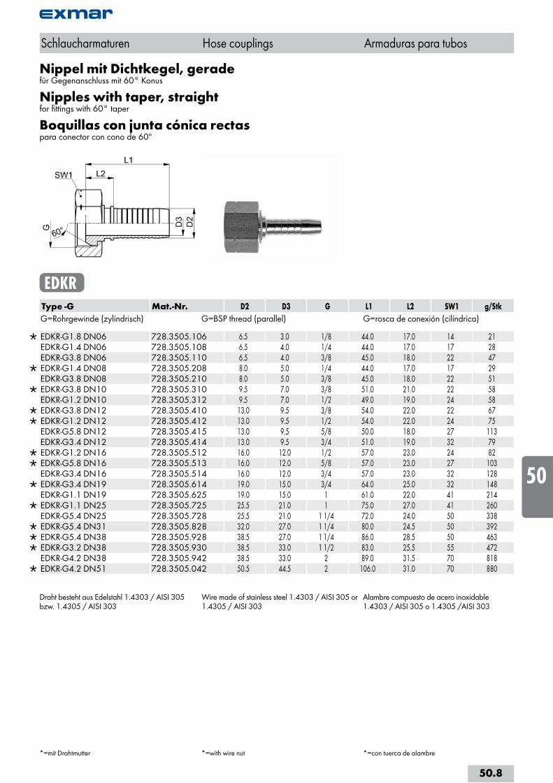
Nippel mit Dichtkegel, geradefür Gegenanschluss mit 60° Konus
Nipples with taper, straightfor fittings with 60° taper
Boquillas con junta cónica rectaspara conector con cono de 60º
EDKRType -G Mat.-Nr. D2 D3 G L1 L2 SW1 g/StkG=Rohrgewinde (zylindrisch) G=BSP thread (parallel) G=rosca de conexión (cilíndrica)
EDKR-G1.8 DN06 728.3505.106 6.5 3.0 1/8 44.0 17.0 14 21 EDKR-G1.4 DN06 728.3505.108 6.5 4.0 1/4 44.0 17.0 17 28 EDKR-G3.8 DN06 728.3505.110 6.5 4.0 3/8 45.0 18.0 22 47
EDKR-G1.4 DN08 728.3505.208 8.0 5.0 1/4 44.0 17.0 17 29 EDKR-G3.8 DN08 728.3505.210 8.0 5.0 3/8 45.0 18.0 22 51
EDKR-G3.8 DN10 728.3505.310 9.5 7.0 3/8 51.0 21.0 22 58 EDKR-G1.2 DN10 728.3505.312 9.5 7.0 1/2 49.0 19.0 24 58
EDKR-G3.8 DN12 728.3505.410 13.0 9.5 3/8 54.0 22.0 22 67 EDKR-G1.2 DN12 728.3505.412 13.0 9.5 1/2 54.0 22.0 24 75 EDKR-G5.8 DN12 728.3505.415 13.0 9.5 5/8 50.0 18.0 27 113 EDKR-G3.4 DN12 728.3505.414 13.0 9.5 3/4 51.0 19.0 32 79
EDKR-G1.2 DN16 728.3505.512 16.0 12.0 1/2 57.0 23.0 24 82 EDKR-G5.8 DN16 728.3505.513 16.0 12.0 5/8 57.0 23.0 27 103 EDKR-G3.4 DN16 728.3505.514 16.0 12.0 3/4 57.0 23.0 32 128
EDKR-G3.4 DN19 728.3505.614 19.0 15.0 3/4 64.0 25.0 32 148 EDKR-G1.1 DN19 728.3505.625 19.0 15.0 1 61.0 22.0 41 214
EDKR-G1.1 DN25 728.3505.725 25.5 21.0 1 75.0 27.0 41 260 EDKR-G5.4 DN25 728.3505.728 25.5 21.0 1 1/4 72.0 24.0 50 338
EDKR-G5.4 DN31 728.3505.828 32.0 27.0 1 1/4 80.0 24.5 50 392 EDKR-G5.4 DN38 728.3505.928 38.5 27.0 1 1/4 86.0 28.5 50 463 EDKR-G3.2 DN38 728.3505.930 38.5 33.0 1 1/2 83.0 25.5 55 472 EDKR-G4.2 DN38 728.3505.942 38.5 33.0 2 89.0 31.5 70 818
EDKR-G4.2 DN51 728.3505.042 50.5 44.5 2 106.0 31.0 70 880
Draht besteht aus Edelstahl 1.4303 / AISI 305 bzw. 1.4305 / AISI 303
Wire made of stainless steel 1.4303 / AISI 305 or 1.4305 / AISI 303
Alambre compuesto de acero inoxidable 1.4303 / AISI 305 o 1.4305 /AISI 303
Schlaucharmaturen Hose couplings Armaduras para tubos
*=mit Drahtmutter *=with wire nut *=con tuerca de alambre
50.8
i
s
10
20
30
40
50
60
70
80
a
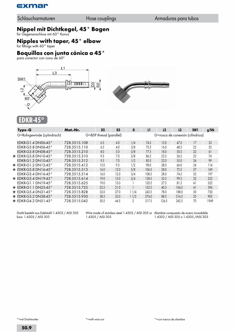
Nippel mit Dichtkegel, 45° Bogenfür Gegenanschluss mit 60° Konus
Nipples with taper, 45° elbowfor fittings with 60° taper
Boquillas con junta cónica a 45°para conector con cono de 60º
EDKR-45°Type -G Mat.-Nr. D2 D3 G L1 L2 L3 SW1 g/StkG=Rohrgewinde (zylindrisch) G=BSP thread (parallel) G=rosca de conexión (cilíndrica)
EDKR-G1.4 DN06-45° 728.3515.108 6.5 4.0 1/4 74.5 15.0 47.5 17 33 EDKR-G3.8 DN06-45° 728.3515.110 6.5 4.0 3/8 75.5 16.0 48.5 22 55 EDKR-G3.8 DN08-45° 728.3515.210 8.0 5.0 3/8 77.5 18.0 50.5 22 61
EDKR-G3.8 DN10-45° 728.3515.310 9.5 7.0 3/8 86.5 23.5 56.5 22 74 EDKR-G1.2 DN10-45° 728.3515.312 9.5 7.0 1/2 85.0 22.0 55.0 24 99
EDKR-G1.2 DN12-45° 728.3515.412 13.0 9.5 1/2 98.0 28.0 66.0 24 114 EDKR-G5.8 DN16-45° 728.3515.513 16.0 12.0 5/8 106.5 28.0 72.5 27 169 EDKR-G3.4 DN16-45° 728.3515.514 16.0 12.0 3/4 108.5 28.0 74.5 32 197
EDKR-G3.4 DN19-45° 728.3515.614 19.0 15.0 3/4 138.5 33.5 99.5 32 252 EDKR-G1.1 DN19-45° 728.3515.625 19.0 15.0 1 120.5 27.5 81.5 41 322
EDKR-G1.1 DN25-45° 728.3515.725 25.5 21.0 1 152.5 40.5 104.5 41 396 EDKR-G5.4 DN31-45° 728.3515.828 32.0 27.0 1 1/4 243.5 78.0 188.0 50 730 EDKR-G3.2 DN38-45° 728.3515.930 38.5 33.0 1 1/2 274.0 88.5 216.5 55 905 EDKR-G4.2 DN51-45° 728.3515.042 50.5 44.5 2 317.5 126.5 242.5 70 1949
Draht besteht aus Edelstahl 1.4303 / AISI 305 bzw. 1.4305 / AISI 303
Wire made of stainless steel 1.4303 / AISI 305 or 1.4305 / AISI 303
Alambre compuesto de acero inoxidable 1.4303 / AISI 305 o 1.4305 /AISI 303
Schlaucharmaturen Hose couplings Armaduras para tubos
*=mit Drahtmutter *=with wire nut *=con tuerca de alambre
50.9
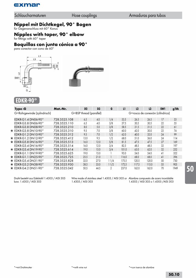
Nippel mit Dichtkegel, 90° Bogenfür Gegenanschluss mit 60° Konus
Nipples with taper, 90° elbowfor fittings with 60° taper
Boquillas con junta cónica a 90°para conector con cono de 60º
EDKR-90°Type -G Mat.-Nr. D2 D3 G L1 L2 L3 SW1 g/StkG=Rohrgewinde (zylindrisch) G=BSP thread (parallel) G=rosca de conexión (cilíndrica)
EDKR-G1.4 DN06-90° 728.3525.108 6.5 4.0 1/4 53.5 26.5 26.5 17 33 EDKR-G3.8 DN06-90° 728.3525.110 6.5 4.0 3/8 57.5 30.5 30.5 22 55 EDKR-G3.8 DN08-90° 728.3525.210 8.0 5.0 3/8 58.5 31.5 31.5 22 61
EDKR-G3.8 DN10-90° 728.3525.310 9.5 7.0 3/8 60.0 42.0 30.0 22 74 EDKR-G1.2 DN10-90° 728.3525.312 9.5 7.0 1/2 62.0 40.0 32.0 24 99
EDKR-G1.2 DN12-90° 728.3525.412 13.0 9.5 1/2 68.0 51.0 36.0 24 114 EDKR-G5.8 DN16-90° 728.3525.513 16.0 12.0 5/8 81.5 47.5 47.5 27 169 EDKR-G3.4 DN16-90° 728.3525.514 16.0 12.0 3/4 82.5 48.5 48.5 32 197
EDKR-G3.4 DN19-90° 728.3525.614 19.0 15.0 3/4 101.0 63.0 62.0 32 252 EDKR-G1.1 DN19-90° 728.3525.625 19.0 15.0 1 93.0 54.0 54.0 41 322
EDKR-G1.1 DN25-90° 728.3525.725 25.5 21.0 1 116.0 68.0 68.0 41 396 EDKR-G5.4 DN31-90° 728.3525.828 32.0 27.0 1 1/4 175.5 120.5 120.0 50 730 EDKR-G3.2 DN38-90° 728.3525.930 38.5 33.0 1 1/2 172.5 117.5 115.0 55 905 EDKR-G4.2 DN51-90° 728.3525.042 50.5 44.5 2 237.0 162.0 162.0 70 1949
Draht besteht aus Edelstahl 1.4303 / AISI 305 bzw. 1.4305 / AISI 303
Wire made of stainless steel 1.4303 / AISI 305 or 1.4305 / AISI 303
Alambre compuesto de acero inoxidable 1.4303 / AISI 305 o 1.4305 /AISI 303
Schlaucharmaturen Hose couplings Armaduras para tubos
*=mit Drahtmutter *=with wire nut *=con tuerca de alambre
50.10
i
s
10
20
30
40
50
60
70
80
a
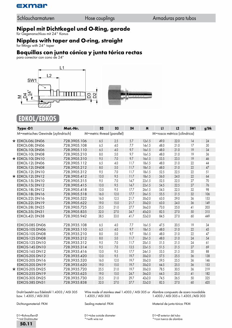
Nippel mit Dichtkegel und O-Ring, geradefür Gegenanschluss mit 24° Konus
Nipples with taper and O-ring, straightfor fittings with 24° taper
Boquillas con junta cónica y junta tórica rectaspara conector con cono de 24º
EDKOL/EDKOSType -D1 Mat.-Nr. D2 D3 D4 M L1 L2 SW1 g/StkM=metrisches Gewinde (zylindrisch) M=metric thread (parallel) M=rosca métrica (cilindrica)
EDKOL-06L DN06 728.3905.106 6.5 2.5 5.7 12x1.5 49.0 22.0 14 24 EDKOL-08L DN06 728.3905.108 6.5 4.0 7.7 14x1.5 48.0 21.0 17 30 EDKOL-10L DN06 728.3905.110 6.5 4.0 9.7 16x1.5 48.0 21.0 19 34 EDKOL-10L DN08 728.3905.210 8.0 5.0 9.7 16x1.5 48.0 21.0 19 36
EDKOL-10L DN10 728.3905.310 9.5 7.0 9.7 16x1.5 53.5 23.5 19 46 EDKOL-12L DN06 728.3905.112 6.5 4.0 11.7 18x1.5 48.0 21.0 22 44 EDKOL-12L DN08 728.3905.212 8.0 5.0 11.7 18x1.5 48.0 21.0 22 47 EDKOL-12L DN10 728.3905.312 9.5 7.0 11.7 18x1.5 52.5 22.5 22 51
EDKOL-12L DN12 728.3905.412 13.0 9.5 11.7 18x1.5 56.0 24.0 22 64 EDKOL-15L DN10 728.3905.315 9.5 7.0 14.7 22x1.5 52.5 22.5 27 70 EDKOL-15L DN12 728.3905.415 13.0 9.5 14.7 22x1.5 54.5 22.5 27 76 EDKOL-18L DN12 728.3905.418 13.0 9.5 17.7 26x1.5 54.5 22.5 32 98 EDKOL-18L DN16 728.3905.518 16.0 12.0 17.7 26x1.5 55.5 21.5 32 106 EDKOL-22L DN16 728.3905.522 16.0 12.5 21.7 30x2.0 63.0 29.0 36 153 EDKOL-22L DN19 728.3905.622 19.0 15.0 21.7 30x2.0 63.0 24.0 36 149 EDKOL-28L DN25 728.3905.725 25.5 21.0 27.7 36x2.0 73.0 25.0 41 203 EDKOL-35L DN31 728.3905.835 32.0 27.0 34.7 45x2.0 82.5 27.0 50 315 EDKOL-42L DN38 728.3905.942 38.5 33.0 41.7 52x2.0 84.5 27.0 60 449 EDKOS-08S DN06 728.3935.108 6.5 4.0 7.7 16x1.5 47.5 20.5 19 34 EDKOS-10S DN06 728.3935.110 6.5 4.0 9.7 18x1.5 48.0 21.0 22 45 EDKOS-10S DN08 728.3935.210 8.0 5.0 9.7 18x1.5 48.0 21.0 22 47 EDKOS-12S DN08 728.3935.212 8.0 5.0 11.7 20x1.5 48.0 21.0 24 54 EDKOS-12S DN10 728.3935.312 9.5 7.0 11.7 20x1.5 51.5 21.5 24 61 EDKOS-14S DN10 728.3935.314 9.5 7.0 13.5 22x1.5 51.5 21.5 27 69 EDKOS-16S DN12 728.3935.416 13.0 9.5 17.7 24x1.5 53.5 21.5 30 88 EDKOS-20S DN12 728.3935.420 13.0 9.5 19.7 30x2.0 57.5 25.5 36 138 EDKOS-20S DN16 728.3935.520 16.0 12.0 19.7 30x2.0 59.5 25.5 36 146 EDKOS-20S DN19 728.3935.620 19.0 15.0 19.7 30x2.0 64.5 25.5 36 153
EDKOS-20S DN25 728.3935.720 25.5 21.0 19.7 30x2.0 78.5 30.5 36 219 EDKOS-25S DN19 728.3935.625 19.0 15.0 24.7 36x2.0 64.5 25.5 41 182 EDKOS-30S DN25 728.3935.730 25.5 21.0 29.7 42x2.0 74.5 26.5 50 325 EDKOS-38S DN31 728.3935.838 32.0 27.0 37.7 52x2.0 82.5 27.0 60 420
Schlaucharmaturen Hose couplings Armaduras para tubos
D1=Rohraußen-Ø*=mit Drahtmutter
D1=tube outside diameter*=with wire nut
D1=Ø exterior del tubo*=con tuerca de alambre
Draht besteht aus Edelstahl 1.4303 / AISI 305 bzw. 1.4305 / AISI 303
Dichtungsmaterial: FKM
Wire made of stainless steel 1.4303 / AISI 305 or 1.4305 / AISI 303
Sealing material: FKM
Alambre compuesto de acero inoxidable 1.4303 / AISI 305 o 1.4305 /AISI 303
Material de junta tórica: FKM
50.11
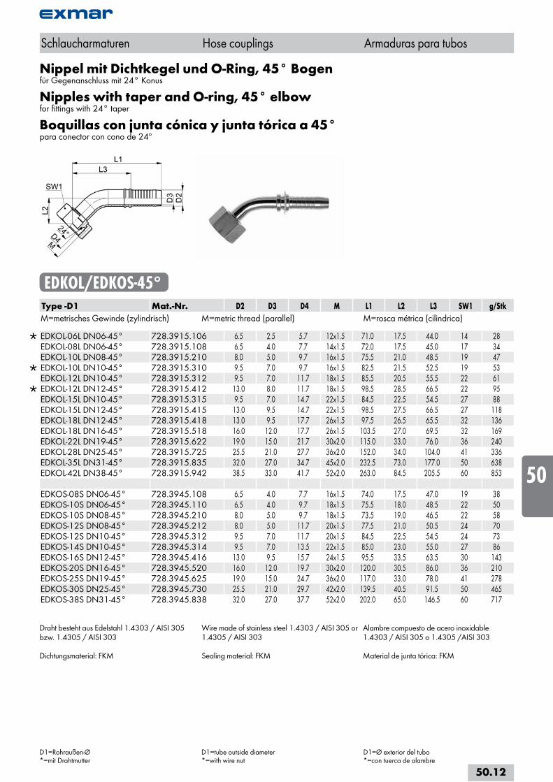
Nippel mit Dichtkegel und O-Ring, 45° Bogenfür Gegenanschluss mit 24° Konus
Nipples with taper and O-ring, 45° elbowfor fittings with 24° taper
Boquillas con junta cónica y junta tórica a 45°para conector con cono de 24º
EDKOL/EDKOS-45°Type -D1 Mat.-Nr. D2 D3 D4 M L1 L2 L3 SW1 g/StkM=metrisches Gewinde (zylindrisch) M=metric thread (parallel) M=rosca métrica (cilindrica)
EDKOL-06L DN06-45° 728.3915.106 6.5 2.5 5.7 12x1.5 71.0 17.5 44.0 14 28 EDKOL-08L DN06-45° 728.3915.108 6.5 4.0 7.7 14x1.5 72.0 17.5 45.0 17 34 EDKOL-10L DN08-45° 728.3915.210 8.0 5.0 9.7 16x1.5 75.5 21.0 48.5 19 47
EDKOL-10L DN10-45° 728.3915.310 9.5 7.0 9.7 16x1.5 82.5 21.5 52.5 19 53 EDKOL-12L DN10-45° 728.3915.312 9.5 7.0 11.7 18x1.5 85.5 20.5 55.5 22 61
EDKOL-12L DN12-45° 728.3915.412 13.0 8.0 11.7 18x1.5 98.5 28.5 66.5 22 95 EDKOL-15L DN10-45° 728.3915.315 9.5 7.0 14.7 22x1.5 84.5 22.5 54.5 27 88 EDKOL-15L DN12-45° 728.3915.415 13.0 9.5 14.7 22x1.5 98.5 27.5 66.5 27 118 EDKOL-18L DN12-45° 728.3915.418 13.0 9.5 17.7 26x1.5 97.5 26.5 65.5 32 136 EDKOL-18L DN16-45° 728.3915.518 16.0 12.0 17.7 26x1.5 103.5 27.0 69.5 32 169 EDKOL-22L DN19-45° 728.3915.622 19.0 15.0 21.7 30x2.0 115.0 33.0 76.0 36 240 EDKOL-28L DN25-45° 728.3915.725 25.5 21.0 27.7 36x2.0 152.0 34.0 104.0 41 336 EDKOL-35L DN31-45° 728.3915.835 32.0 27.0 34.7 45x2.0 232.5 73.0 177.0 50 638 EDKOL-42L DN38-45° 728.3915.942 38.5 33.0 41.7 52x2.0 263.0 84.5 205.5 60 853 EDKOS-08S DN06-45° 728.3945.108 6.5 4.0 7.7 16x1.5 74.0 17.5 47.0 19 38 EDKOS-10S DN06-45° 728.3945.110 6.5 4.0 9.7 18x1.5 75.5 18.0 48.5 22 50 EDKOS-10S DN08-45° 728.3945.210 8.0 5.0 9.7 18x1.5 73.5 19.0 46.5 22 58 EDKOS-12S DN08-45° 728.3945.212 8.0 5.0 11.7 20x1.5 77.5 21.0 50.5 24 70 EDKOS-12S DN10-45° 728.3945.312 9.5 7.0 11.7 20x1.5 84.5 22.5 54.5 24 73 EDKOS-14S DN10-45° 728.3945.314 9.5 7.0 13.5 22x1.5 85.0 23.0 55.0 27 86 EDKOS-16S DN12-45° 728.3945.416 13.0 9.5 15.7 24x1.5 95.5 33.5 63.5 30 143 EDKOS-20S DN16-45° 728.3945.520 16.0 12.0 19.7 30x2.0 120.0 30.5 86.0 36 210 EDKOS-25S DN19-45° 728.3945.625 19.0 15.0 24.7 36x2.0 117.0 33.0 78.0 41 278 EDKOS-30S DN25-45° 728.3945.730 25.5 21.0 29.7 42x2.0 139.5 40.5 91.5 50 465 EDKOS-38S DN31-45° 728.3945.838 32.0 27.0 37.7 52x2.0 202.0 65.0 146.5 60 717
Draht besteht aus Edelstahl 1.4303 / AISI 305 bzw. 1.4305 / AISI 303
Dichtungsmaterial: FKM
Wire made of stainless steel 1.4303 / AISI 305 or 1.4305 / AISI 303
Sealing material: FKM
Alambre compuesto de acero inoxidable 1.4303 / AISI 305 o 1.4305 /AISI 303
Material de junta tórica: FKM
Schlaucharmaturen Hose couplings Armaduras para tubos
D1=Rohraußen-Ø*=mit Drahtmutter
D1=tube outside diameter*=with wire nut
D1=Ø exterior del tubo*=con tuerca de alambre
50.12
i
s
10
20
30
40
50
60
70
80
a
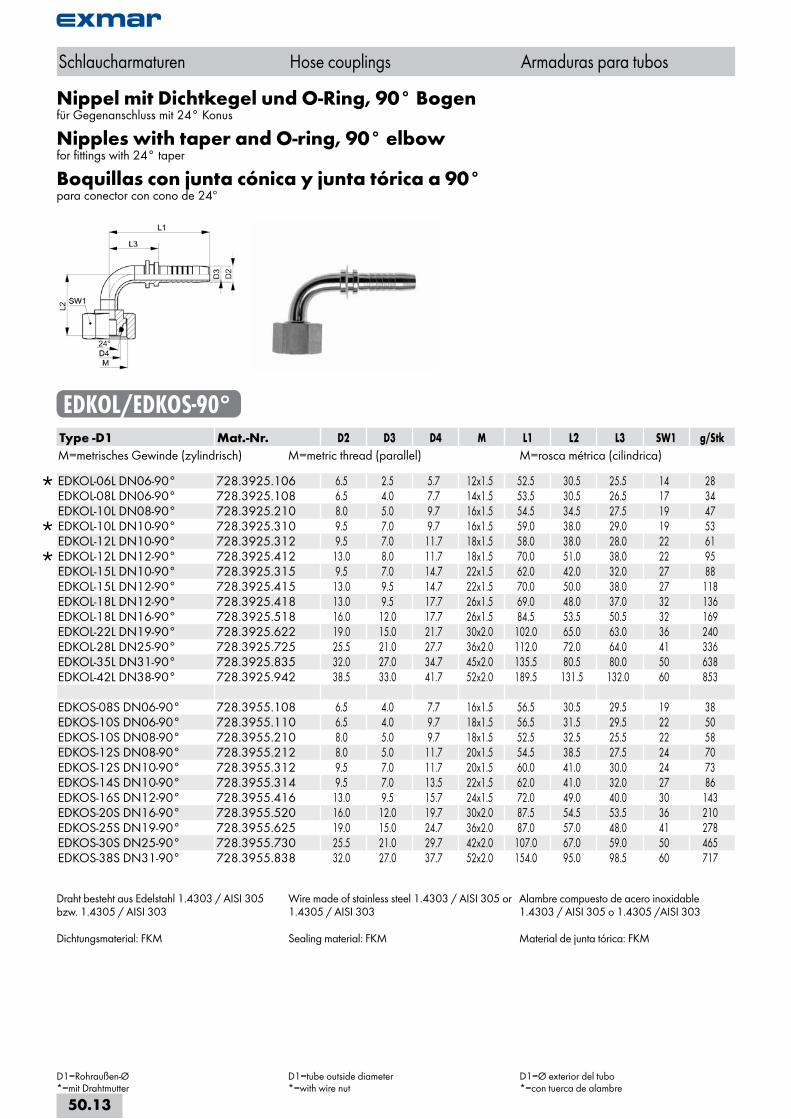
Nippel mit Dichtkegel und O-Ring, 90° Bogenfür Gegenanschluss mit 24° Konus
Nipples with taper and O-ring, 90° elbowfor fittings with 24° taper
Boquillas con junta cónica y junta tórica a 90°para conector con cono de 24º
EDKOL/EDKOS-90°Type -D1 Mat.-Nr. D2 D3 D4 M L1 L2 L3 SW1 g/StkM=metrisches Gewinde (zylindrisch) M=metric thread (parallel) M=rosca métrica (cilindrica)
EDKOL-06L DN06-90° 728.3925.106 6.5 2.5 5.7 12x1.5 52.5 30.5 25.5 14 28 EDKOL-08L DN06-90° 728.3925.108 6.5 4.0 7.7 14x1.5 53.5 30.5 26.5 17 34 EDKOL-10L DN08-90° 728.3925.210 8.0 5.0 9.7 16x1.5 54.5 34.5 27.5 19 47
EDKOL-10L DN10-90° 728.3925.310 9.5 7.0 9.7 16x1.5 59.0 38.0 29.0 19 53 EDKOL-12L DN10-90° 728.3925.312 9.5 7.0 11.7 18x1.5 58.0 38.0 28.0 22 61
EDKOL-12L DN12-90° 728.3925.412 13.0 8.0 11.7 18x1.5 70.0 51.0 38.0 22 95 EDKOL-15L DN10-90° 728.3925.315 9.5 7.0 14.7 22x1.5 62.0 42.0 32.0 27 88 EDKOL-15L DN12-90° 728.3925.415 13.0 9.5 14.7 22x1.5 70.0 50.0 38.0 27 118 EDKOL-18L DN12-90° 728.3925.418 13.0 9.5 17.7 26x1.5 69.0 48.0 37.0 32 136 EDKOL-18L DN16-90° 728.3925.518 16.0 12.0 17.7 26x1.5 84.5 53.5 50.5 32 169 EDKOL-22L DN19-90° 728.3925.622 19.0 15.0 21.7 30x2.0 102.0 65.0 63.0 36 240 EDKOL-28L DN25-90° 728.3925.725 25.5 21.0 27.7 36x2.0 112.0 72.0 64.0 41 336 EDKOL-35L DN31-90° 728.3925.835 32.0 27.0 34.7 45x2.0 135.5 80.5 80.0 50 638 EDKOL-42L DN38-90° 728.3925.942 38.5 33.0 41.7 52x2.0 189.5 131.5 132.0 60 853 EDKOS-08S DN06-90° 728.3955.108 6.5 4.0 7.7 16x1.5 56.5 30.5 29.5 19 38 EDKOS-10S DN06-90° 728.3955.110 6.5 4.0 9.7 18x1.5 56.5 31.5 29.5 22 50 EDKOS-10S DN08-90° 728.3955.210 8.0 5.0 9.7 18x1.5 52.5 32.5 25.5 22 58 EDKOS-12S DN08-90° 728.3955.212 8.0 5.0 11.7 20x1.5 54.5 38.5 27.5 24 70 EDKOS-12S DN10-90° 728.3955.312 9.5 7.0 11.7 20x1.5 60.0 41.0 30.0 24 73 EDKOS-14S DN10-90° 728.3955.314 9.5 7.0 13.5 22x1.5 62.0 41.0 32.0 27 86 EDKOS-16S DN12-90° 728.3955.416 13.0 9.5 15.7 24x1.5 72.0 49.0 40.0 30 143 EDKOS-20S DN16-90° 728.3955.520 16.0 12.0 19.7 30x2.0 87.5 54.5 53.5 36 210 EDKOS-25S DN19-90° 728.3955.625 19.0 15.0 24.7 36x2.0 87.0 57.0 48.0 41 278 EDKOS-30S DN25-90° 728.3955.730 25.5 21.0 29.7 42x2.0 107.0 67.0 59.0 50 465 EDKOS-38S DN31-90° 728.3955.838 32.0 27.0 37.7 52x2.0 154.0 95.0 98.5 60 717
Draht besteht aus Edelstahl 1.4303 / AISI 305 bzw. 1.4305 / AISI 303
Dichtungsmaterial: FKM
Wire made of stainless steel 1.4303 / AISI 305 or 1.4305 / AISI 303
Sealing material: FKM
Alambre compuesto de acero inoxidable 1.4303 / AISI 305 o 1.4305 /AISI 303
Material de junta tórica: FKM
Schlaucharmaturen Hose couplings Armaduras para tubos
D1=Rohraußen-Ø*=mit Drahtmutter
D1=tube outside diameter*=with wire nut
D1=Ø exterior del tubo*=con tuerca de alambre
50.13
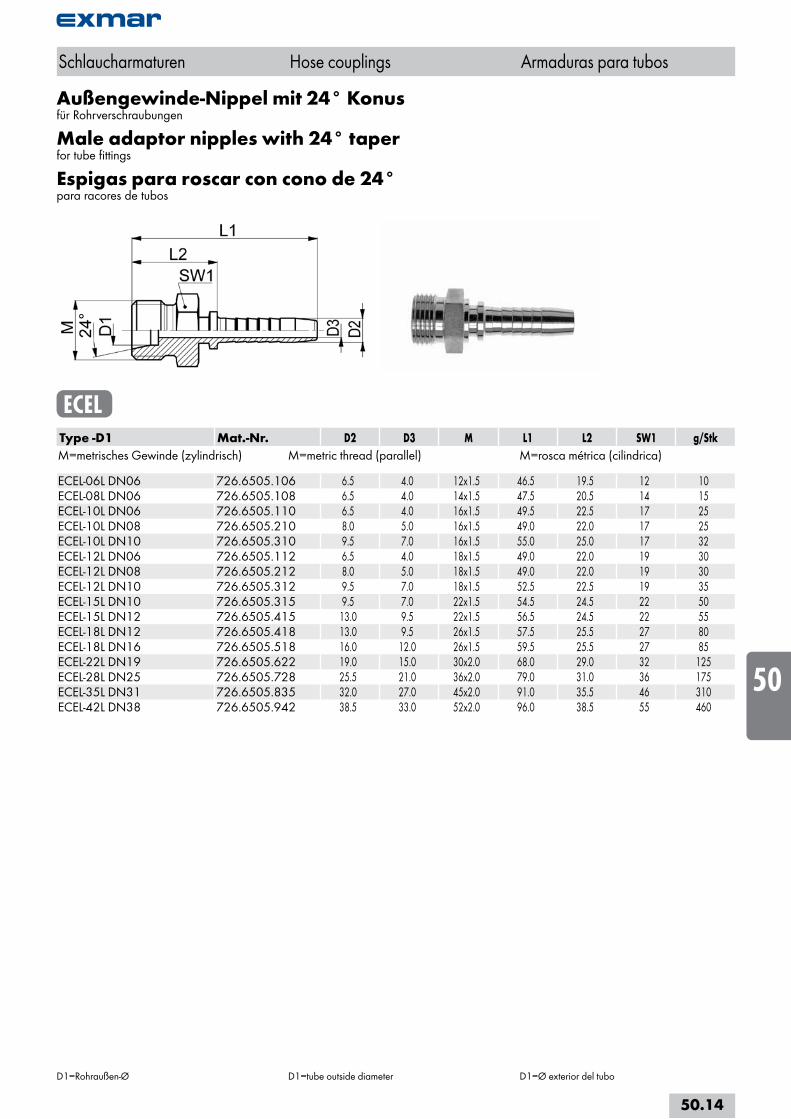
Außengewinde-Nippel mit 24° Konusfür Rohrverschraubungen
Male adaptor nipples with 24° taperfor tube fittings
Espigas para roscar con cono de 24°para racores de tubos
ECELType -D1 Mat.-Nr. D2 D3 M L1 L2 SW1 g/StkM=metrisches Gewinde (zylindrisch) M=metric thread (parallel) M=rosca métrica (cilindrica) ECEL-06L DN06 726.6505.106 6.5 4.0 12x1.5 46.5 19.5 12 10ECEL-08L DN06 726.6505.108 6.5 4.0 14x1.5 47.5 20.5 14 15ECEL-10L DN06 726.6505.110 6.5 4.0 16x1.5 49.5 22.5 17 25ECEL-10L DN08 726.6505.210 8.0 5.0 16x1.5 49.0 22.0 17 25ECEL-10L DN10 726.6505.310 9.5 7.0 16x1.5 55.0 25.0 17 32ECEL-12L DN06 726.6505.112 6.5 4.0 18x1.5 49.0 22.0 19 30ECEL-12L DN08 726.6505.212 8.0 5.0 18x1.5 49.0 22.0 19 30ECEL-12L DN10 726.6505.312 9.5 7.0 18x1.5 52.5 22.5 19 35ECEL-15L DN10 726.6505.315 9.5 7.0 22x1.5 54.5 24.5 22 50ECEL-15L DN12 726.6505.415 13.0 9.5 22x1.5 56.5 24.5 22 55ECEL-18L DN12 726.6505.418 13.0 9.5 26x1.5 57.5 25.5 27 80ECEL-18L DN16 726.6505.518 16.0 12.0 26x1.5 59.5 25.5 27 85ECEL-22L DN19 726.6505.622 19.0 15.0 30x2.0 68.0 29.0 32 125ECEL-28L DN25 726.6505.728 25.5 21.0 36x2.0 79.0 31.0 36 175ECEL-35L DN31 726.6505.835 32.0 27.0 45x2.0 91.0 35.5 46 310ECEL-42L DN38 726.6505.942 38.5 33.0 52x2.0 96.0 38.5 55 460
Schlaucharmaturen Hose couplings Armaduras para tubos
D1=Rohraußen-Ø D1=tube outside diameter D1=Ø exterior del tubo
50.14
i
s
10
20
30
40
50
60
70
80
a
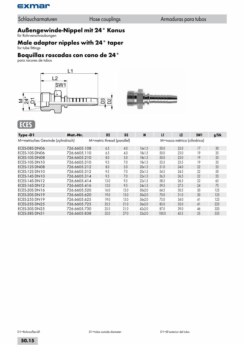
Außengewinde-Nippel mit 24° Konusfür Rohrverschraubungen
Male adaptor nipples with 24° taperfor tube fittings
Boquillas roscadas con cono de 24°para racores de tubos
ECESType -D1 Mat.-Nr. D2 D3 M L1 L2 SW1 g/StkM=metrisches Gewinde (zylindrisch) M=metric thread (parallel) M=rosca métrica (cilindrica) ECES-08S DN06 726.6605.108 6.5 4.0 16x1.5 50.0 23.0 17 30ECES-10S DN06 726.6605.110 6.5 4.0 18x1.5 50.0 23.0 19 35ECES-10S DN08 726.6605.210 8.0 5.0 18x1.5 50.0 23.0 19 35ECES-10S DN10 726.6605.310 9.5 7.0 18x1.5 53.5 23.5 19 35ECES-12S DN08 726.6605.212 8.0 5.0 20x1.5 51.0 24.0 22 55ECES-12S DN10 726.6605.312 9.5 7.0 20x1.5 54.5 24.5 22 50ECES-14S DN10 726.6605.314 9.5 7.0 22x1.5 56.5 26.5 22 55ECES-14S DN12 726.6605.414 13.0 9.5 22x1.5 58.5 26.5 22 65ECES-16S DN12 726.6605.416 13.0 9.5 24x1.5 59.5 27.5 24 75ECES-20S DN16 726.6605.520 16.0 12.0 30x2.0 64.5 30.5 30 125ECES-20S DN19 726.6605.620 19.0 15.0 30x2.0 70.0 31.0 30 125ECES-25S DN19 726.6605.625 19.0 15.0 36x2.0 73.0 34.0 41 125ECES-25S DN25 726.6605.725 25.5 21.0 36x2.0 83.0 35.0 41 225ECES-30S DN25 726.6605.730 25.5 21.0 42x2.0 87.0 39.0 46 320ECES-38S DN31 726.6605.838 32.0 27.0 52x2.0 100.0 45.5 55 535
Schlaucharmaturen Hose couplings Armaduras para tubos
D1=Rohraußen-Ø D1=tube outside diameter D1=Ø exterior del tubo
50.15
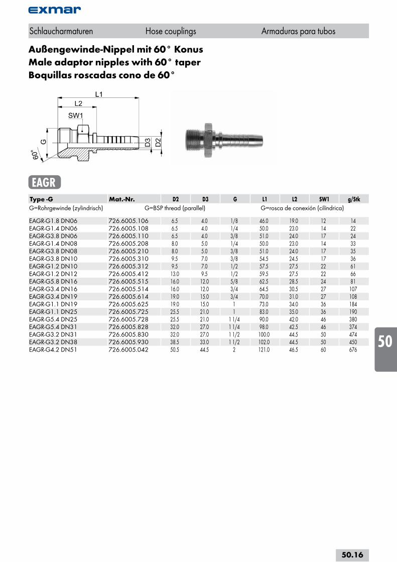
Außengewinde-Nippel mit 60° KonusMale adaptor nipples with 60° taperBoquillas roscadas cono de 60°
EAGRType -G Mat.-Nr. D2 D3 G L1 L2 SW1 g/StkG=Rohrgewinde (zylindrisch) G=BSP thread (parallel) G=rosca de conexión (cilíndrica) EAGR-G1.8 DN06 726.6005.106 6.5 4.0 1/8 46.0 19.0 12 14EAGR-G1.4 DN06 726.6005.108 6.5 4.0 1/4 50.0 23.0 14 22EAGR-G3.8 DN06 726.6005.110 6.5 4.0 3/8 51.0 24.0 17 24EAGR-G1.4 DN08 726.6005.208 8.0 5.0 1/4 50.0 23.0 14 33EAGR-G3.8 DN08 726.6005.210 8.0 5.0 3/8 51.0 24.0 17 35EAGR-G3.8 DN10 726.6005.310 9.5 7.0 3/8 54.5 24.5 17 36EAGR-G1.2 DN10 726.6005.312 9.5 7.0 1/2 57.5 27.5 22 61EAGR-G1.2 DN12 726.6005.412 13.0 9.5 1/2 59.5 27.5 22 66EAGR-G5.8 DN16 726.6005.515 16.0 12.0 5/8 62.5 28.5 24 81EAGR-G3.4 DN16 726.6005.514 16.0 12.0 3/4 64.5 30.5 27 107EAGR-G3.4 DN19 726.6005.614 19.0 15.0 3/4 70.0 31.0 27 108EAGR-G1.1 DN19 726.6005.625 19.0 15.0 1 73.0 34.0 36 184EAGR-G1.1 DN25 726.6005.725 25.5 21.0 1 83.0 35.0 36 190EAGR-G5.4 DN25 726.6005.728 25.5 21.0 1 1/4 90.0 42.0 46 380EAGR-G5.4 DN31 726.6005.828 32.0 27.0 1 1/4 98.0 42.5 46 374EAGR-G3.2 DN31 726.6005.830 32.0 27.0 1 1/2 100.0 44.5 50 474EAGR-G3.2 DN38 726.6005.930 38.5 33.0 1 1/2 102.0 44.5 50 450EAGR-G4.2 DN51 726.6005.042 50.5 44.5 2 121.0 46.5 60 676
Schlaucharmaturen Hose couplings Armaduras para tubos
50.16
i
s
10
20
30
40
50
60
70
80
a
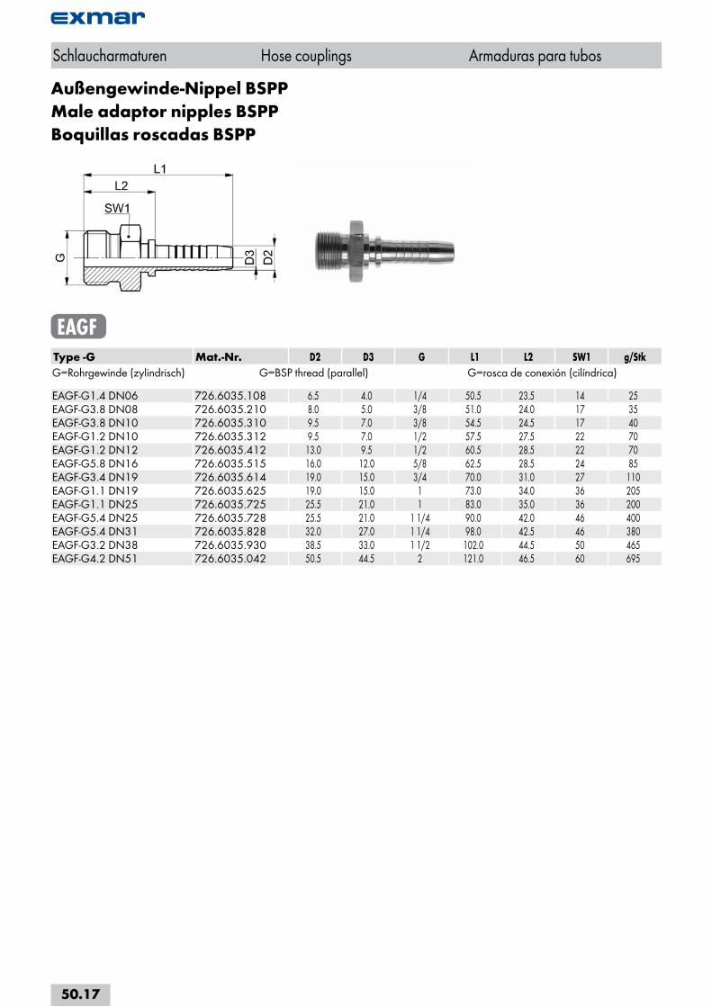
Außengewinde-Nippel BSPPMale adaptor nipples BSPPBoquillas roscadas BSPP
EAGFType -G Mat.-Nr. D2 D3 G L1 L2 SW1 g/StkG=Rohrgewinde (zylindrisch) G=BSP thread (parallel) G=rosca de conexión (cilíndrica) EAGF-G1.4 DN06 726.6035.108 6.5 4.0 1/4 50.5 23.5 14 25EAGF-G3.8 DN08 726.6035.210 8.0 5.0 3/8 51.0 24.0 17 35EAGF-G3.8 DN10 726.6035.310 9.5 7.0 3/8 54.5 24.5 17 40EAGF-G1.2 DN10 726.6035.312 9.5 7.0 1/2 57.5 27.5 22 70EAGF-G1.2 DN12 726.6035.412 13.0 9.5 1/2 60.5 28.5 22 70EAGF-G5.8 DN16 726.6035.515 16.0 12.0 5/8 62.5 28.5 24 85EAGF-G3.4 DN19 726.6035.614 19.0 15.0 3/4 70.0 31.0 27 110EAGF-G1.1 DN19 726.6035.625 19.0 15.0 1 73.0 34.0 36 205EAGF-G1.1 DN25 726.6035.725 25.5 21.0 1 83.0 35.0 36 200EAGF-G5.4 DN25 726.6035.728 25.5 21.0 1 1/4 90.0 42.0 46 400EAGF-G5.4 DN31 726.6035.828 32.0 27.0 1 1/4 98.0 42.5 46 380EAGF-G3.2 DN38 726.6035.930 38.5 33.0 1 1/2 102.0 44.5 50 465EAGF-G4.2 DN51 726.6035.042 50.5 44.5 2 121.0 46.5 60 695
Schlaucharmaturen Hose couplings Armaduras para tubos
50.17
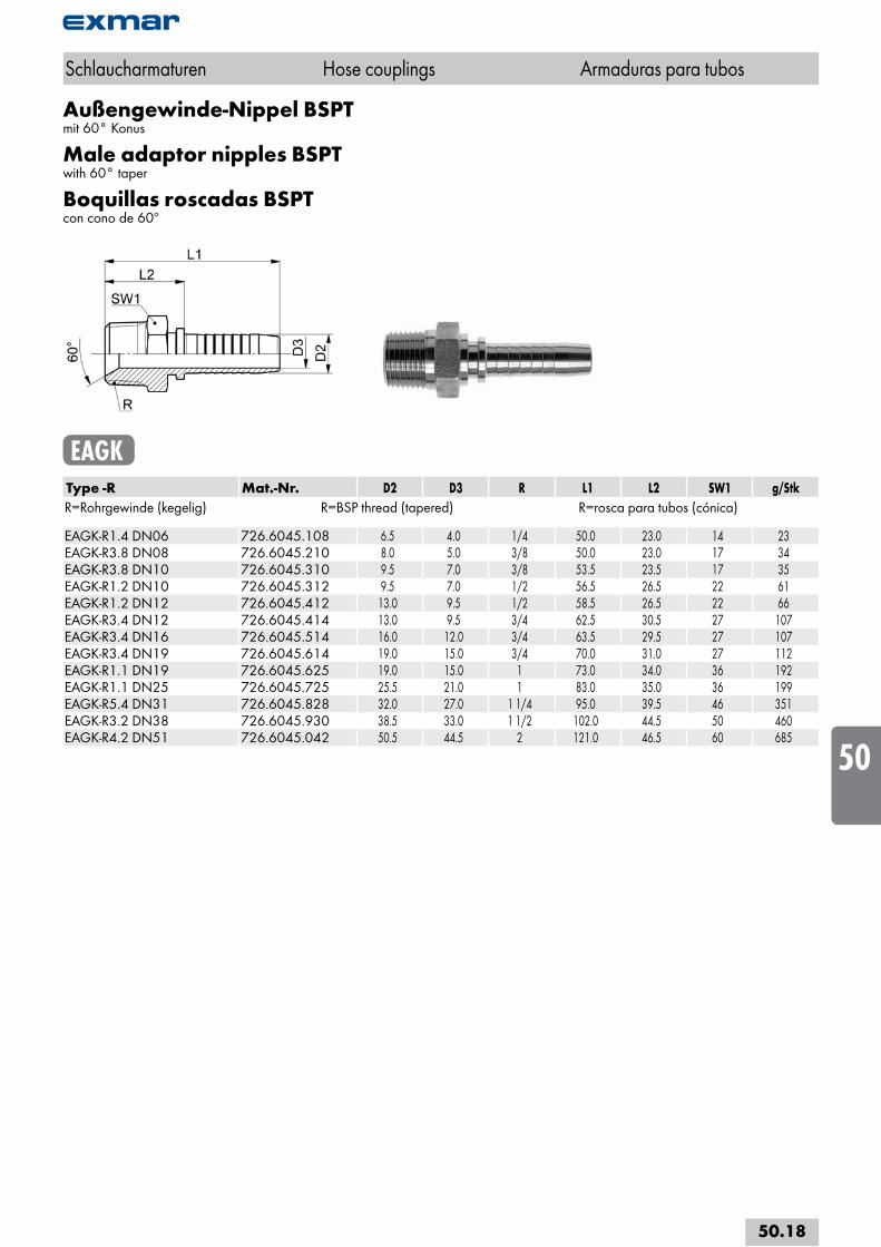
Außengewinde-Nippel BSPTmit 60° Konus
Male adaptor nipples BSPTwith 60° taper
Boquillas roscadas BSPTcon cono de 60º
EAGKType -R Mat.-Nr. D2 D3 R L1 L2 SW1 g/StkR=Rohrgewinde (kegelig) R=BSP thread (tapered) R=rosca para tubos (cónica) EAGK-R1.4 DN06 726.6045.108 6.5 4.0 1/4 50.0 23.0 14 23EAGK-R3.8 DN08 726.6045.210 8.0 5.0 3/8 50.0 23.0 17 34EAGK-R3.8 DN10 726.6045.310 9.5 7.0 3/8 53.5 23.5 17 35EAGK-R1.2 DN10 726.6045.312 9.5 7.0 1/2 56.5 26.5 22 61EAGK-R1.2 DN12 726.6045.412 13.0 9.5 1/2 58.5 26.5 22 66EAGK-R3.4 DN12 726.6045.414 13.0 9.5 3/4 62.5 30.5 27 107EAGK-R3.4 DN16 726.6045.514 16.0 12.0 3/4 63.5 29.5 27 107EAGK-R3.4 DN19 726.6045.614 19.0 15.0 3/4 70.0 31.0 27 112EAGK-R1.1 DN19 726.6045.625 19.0 15.0 1 73.0 34.0 36 192EAGK-R1.1 DN25 726.6045.725 25.5 21.0 1 83.0 35.0 36 199EAGK-R5.4 DN31 726.6045.828 32.0 27.0 1 1/4 95.0 39.5 46 351EAGK-R3.2 DN38 726.6045.930 38.5 33.0 1 1/2 102.0 44.5 50 460EAGK-R4.2 DN51 726.6045.042 50.5 44.5 2 121.0 46.5 60 685
Schlaucharmaturen Hose couplings Armaduras para tubos
50.18
i
s
10
20
30
40
50
60
70
80
a
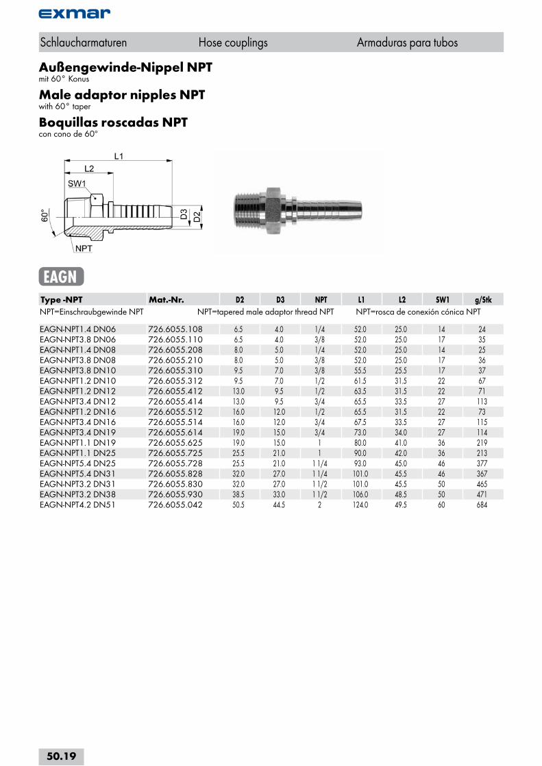
Außengewinde-Nippel NPTmit 60° Konus
Male adaptor nipples NPTwith 60° taper
Boquillas roscadas NPTcon cono de 60º
EAGNType -NPT Mat.-Nr. D2 D3 NPT L1 L2 SW1 g/StkNPT=Einschraubgewinde NPT NPT=tapered male adaptor thread NPT NPT=rosca de conexión cónica NPT EAGN-NPT1.4 DN06 726.6055.108 6.5 4.0 1/4 52.0 25.0 14 24EAGN-NPT3.8 DN06 726.6055.110 6.5 4.0 3/8 52.0 25.0 17 35EAGN-NPT1.4 DN08 726.6055.208 8.0 5.0 1/4 52.0 25.0 14 25EAGN-NPT3.8 DN08 726.6055.210 8.0 5.0 3/8 52.0 25.0 17 36EAGN-NPT3.8 DN10 726.6055.310 9.5 7.0 3/8 55.5 25.5 17 37EAGN-NPT1.2 DN10 726.6055.312 9.5 7.0 1/2 61.5 31.5 22 67EAGN-NPT1.2 DN12 726.6055.412 13.0 9.5 1/2 63.5 31.5 22 71EAGN-NPT3.4 DN12 726.6055.414 13.0 9.5 3/4 65.5 33.5 27 113EAGN-NPT1.2 DN16 726.6055.512 16.0 12.0 1/2 65.5 31.5 22 73EAGN-NPT3.4 DN16 726.6055.514 16.0 12.0 3/4 67.5 33.5 27 115EAGN-NPT3.4 DN19 726.6055.614 19.0 15.0 3/4 73.0 34.0 27 114EAGN-NPT1.1 DN19 726.6055.625 19.0 15.0 1 80.0 41.0 36 219EAGN-NPT1.1 DN25 726.6055.725 25.5 21.0 1 90.0 42.0 36 213EAGN-NPT5.4 DN25 726.6055.728 25.5 21.0 1 1/4 93.0 45.0 46 377EAGN-NPT5.4 DN31 726.6055.828 32.0 27.0 1 1/4 101.0 45.5 46 367EAGN-NPT3.2 DN31 726.6055.830 32.0 27.0 1 1/2 101.0 45.5 50 465EAGN-NPT3.2 DN38 726.6055.930 38.5 33.0 1 1/2 106.0 48.5 50 471EAGN-NPT4.2 DN51 726.6055.042 50.5 44.5 2 124.0 49.5 60 684
Schlaucharmaturen Hose couplings Armaduras para tubos
50.19
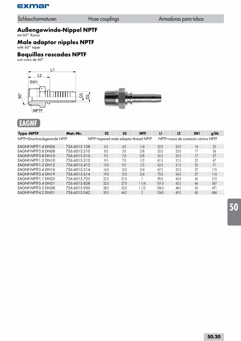
Außengewinde-Nippel NPTFmit 60° Konus
Male adaptor nipples NPTFwith 60° taper
Boquillas roscadas NPTFcon cono de 60º
EAGNFType -NPTF Mat.-Nr. D2 D3 NPTF L1 L2 SW1 g/StkNPTF=Einschraubgewinde NPTF NPTF=tapered male adaptor thread NPTF NPTF=rosca de conexión cónica NPTF EAGNF-NPTF1.4 DN06 726.6015.108 6.5 4.0 1/4 52.0 25.0 14 25EAGNF-NPTF3.8 DN08 726.6015.210 8.0 5.0 3/8 52.0 25.0 17 36EAGNF-NPTF3.8 DN10 726.6015.310 9.5 7.0 3/8 55.5 25.5 17 37EAGNF-NPTF1.2 DN10 726.6015.312 9.5 7.0 1/2 61.5 31.5 22 67EAGNF-NPTF1.2 DN12 726.6015.412 13.0 9.5 1/2 63.5 31.5 22 71EAGNF-NPTF3.4 DN16 726.6015.514 16.0 12.0 3/4 67.5 33.5 27 115EAGNF-NPTF3.4 DN19 726.6015.614 19.0 15.0 3/4 73.0 34.0 27 114EAGNF-NPTF1.1 DN25 726.6015.725 25.5 21.0 1 90.0 42.0 36 213EAGNF-NPTF5.4 DN31 726.6015.828 32.0 27.0 1 1/4 101.0 45.5 46 367EAGNF-NPTF3.2 DN38 726.6015.930 38.5 33.0 1 1/2 106.0 48.5 50 471EAGNF-NPTF4.2 DN51 726.6015.042 50.5 44.5 2 124.0 49.5 60 684
Schlaucharmaturen Hose couplings Armaduras para tubos
50.20
i
s
10
20
30
40
50
60
70
80
a
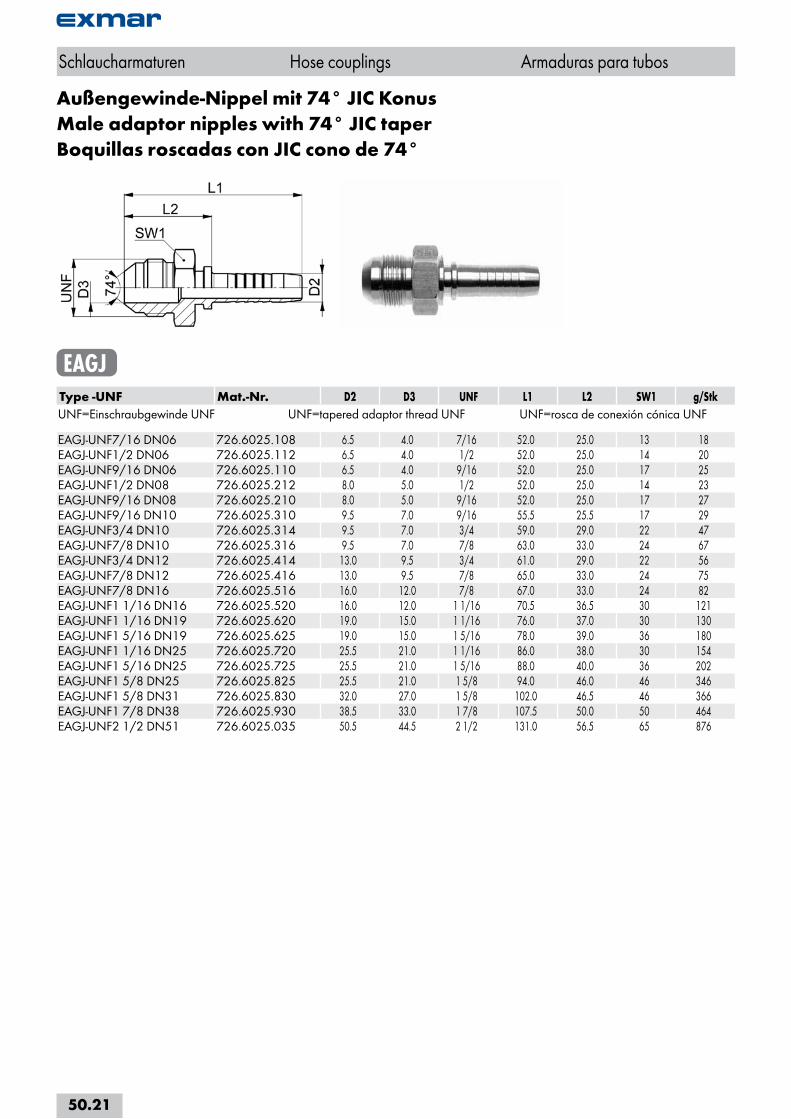
Außengewinde-Nippel mit 74° JIC KonusMale adaptor nipples with 74° JIC taperBoquillas roscadas con JIC cono de 74°
EAGJType -UNF Mat.-Nr. D2 D3 UNF L1 L2 SW1 g/StkUNF=Einschraubgewinde UNF UNF=tapered adaptor thread UNF UNF=rosca de conexión cónica UNF EAGJ-UNF7/16 DN06 726.6025.108 6.5 4.0 7/16 52.0 25.0 13 18EAGJ-UNF1/2 DN06 726.6025.112 6.5 4.0 1/2 52.0 25.0 14 20EAGJ-UNF9/16 DN06 726.6025.110 6.5 4.0 9/16 52.0 25.0 17 25EAGJ-UNF1/2 DN08 726.6025.212 8.0 5.0 1/2 52.0 25.0 14 23EAGJ-UNF9/16 DN08 726.6025.210 8.0 5.0 9/16 52.0 25.0 17 27EAGJ-UNF9/16 DN10 726.6025.310 9.5 7.0 9/16 55.5 25.5 17 29EAGJ-UNF3/4 DN10 726.6025.314 9.5 7.0 3/4 59.0 29.0 22 47EAGJ-UNF7/8 DN10 726.6025.316 9.5 7.0 7/8 63.0 33.0 24 67EAGJ-UNF3/4 DN12 726.6025.414 13.0 9.5 3/4 61.0 29.0 22 56EAGJ-UNF7/8 DN12 726.6025.416 13.0 9.5 7/8 65.0 33.0 24 75EAGJ-UNF7/8 DN16 726.6025.516 16.0 12.0 7/8 67.0 33.0 24 82EAGJ-UNF1 1/16 DN16 726.6025.520 16.0 12.0 1 1/16 70.5 36.5 30 121EAGJ-UNF1 1/16 DN19 726.6025.620 19.0 15.0 1 1/16 76.0 37.0 30 130EAGJ-UNF1 5/16 DN19 726.6025.625 19.0 15.0 1 5/16 78.0 39.0 36 180EAGJ-UNF1 1/16 DN25 726.6025.720 25.5 21.0 1 1/16 86.0 38.0 30 154EAGJ-UNF1 5/16 DN25 726.6025.725 25.5 21.0 1 5/16 88.0 40.0 36 202EAGJ-UNF1 5/8 DN25 726.6025.825 25.5 21.0 1 5/8 94.0 46.0 46 346EAGJ-UNF1 5/8 DN31 726.6025.830 32.0 27.0 1 5/8 102.0 46.5 46 366EAGJ-UNF1 7/8 DN38 726.6025.930 38.5 33.0 1 7/8 107.5 50.0 50 464EAGJ-UNF2 1/2 DN51 726.6025.035 50.5 44.5 2 1/2 131.0 56.5 65 876
Schlaucharmaturen Hose couplings Armaduras para tubos
50.21
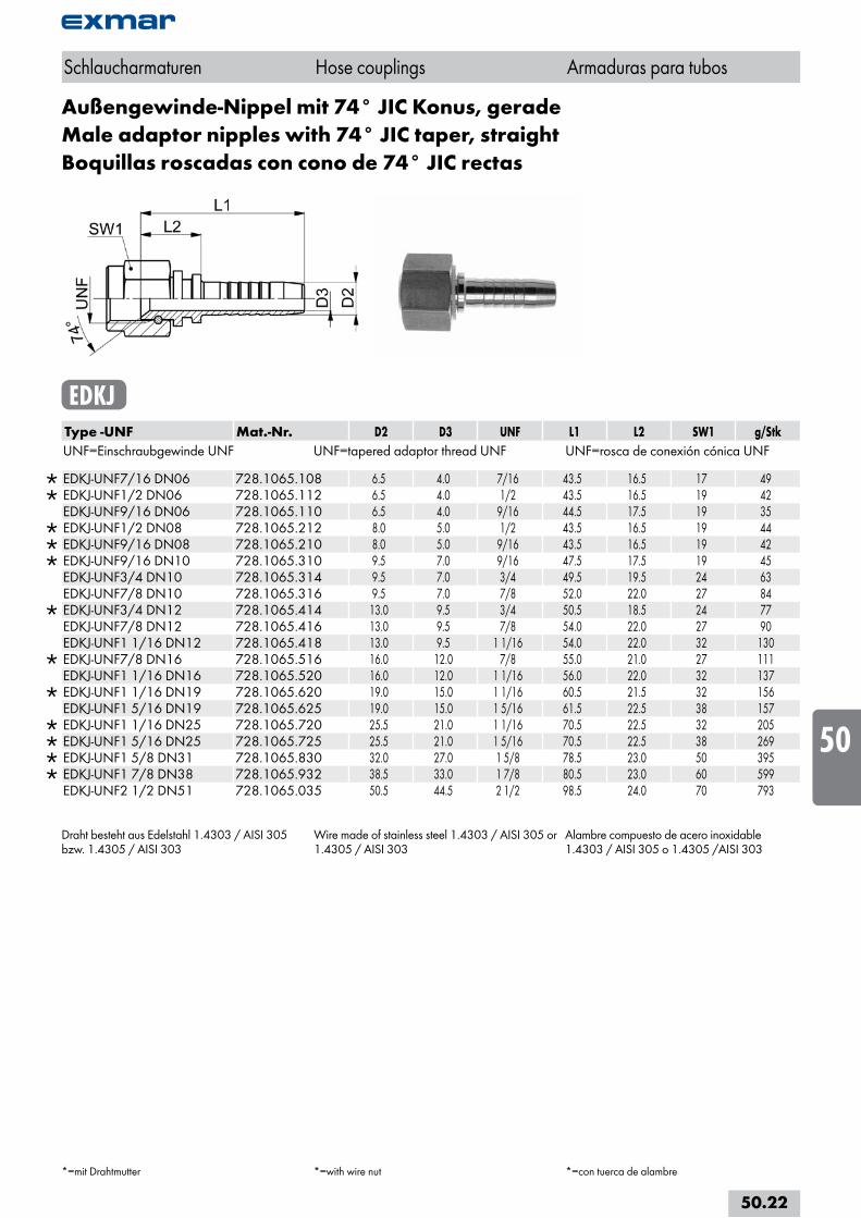
Außengewinde-Nippel mit 74° JIC Konus, geradeMale adaptor nipples with 74° JIC taper, straightBoquillas roscadas con cono de 74° JIC rectas
EDKJType -UNF Mat.-Nr. D2 D3 UNF L1 L2 SW1 g/StkUNF=Einschraubgewinde UNF UNF=tapered adaptor thread UNF UNF=rosca de conexión cónica UNF
EDKJ-UNF7/16 DN06 728.1065.108 6.5 4.0 7/16 43.5 16.5 17 49 EDKJ-UNF1/2 DN06 728.1065.112 6.5 4.0 1/2 43.5 16.5 19 42 EDKJ-UNF9/16 DN06 728.1065.110 6.5 4.0 9/16 44.5 17.5 19 35
EDKJ-UNF1/2 DN08 728.1065.212 8.0 5.0 1/2 43.5 16.5 19 44 EDKJ-UNF9/16 DN08 728.1065.210 8.0 5.0 9/16 43.5 16.5 19 42 EDKJ-UNF9/16 DN10 728.1065.310 9.5 7.0 9/16 47.5 17.5 19 45 EDKJ-UNF3/4 DN10 728.1065.314 9.5 7.0 3/4 49.5 19.5 24 63 EDKJ-UNF7/8 DN10 728.1065.316 9.5 7.0 7/8 52.0 22.0 27 84
EDKJ-UNF3/4 DN12 728.1065.414 13.0 9.5 3/4 50.5 18.5 24 77 EDKJ-UNF7/8 DN12 728.1065.416 13.0 9.5 7/8 54.0 22.0 27 90 EDKJ-UNF1 1/16 DN12 728.1065.418 13.0 9.5 1 1/16 54.0 22.0 32 130
EDKJ-UNF7/8 DN16 728.1065.516 16.0 12.0 7/8 55.0 21.0 27 111 EDKJ-UNF1 1/16 DN16 728.1065.520 16.0 12.0 1 1/16 56.0 22.0 32 137
EDKJ-UNF1 1/16 DN19 728.1065.620 19.0 15.0 1 1/16 60.5 21.5 32 156 EDKJ-UNF1 5/16 DN19 728.1065.625 19.0 15.0 1 5/16 61.5 22.5 38 157
EDKJ-UNF1 1/16 DN25 728.1065.720 25.5 21.0 1 1/16 70.5 22.5 32 205 EDKJ-UNF1 5/16 DN25 728.1065.725 25.5 21.0 1 5/16 70.5 22.5 38 269 EDKJ-UNF1 5/8 DN31 728.1065.830 32.0 27.0 1 5/8 78.5 23.0 50 395 EDKJ-UNF1 7/8 DN38 728.1065.932 38.5 33.0 1 7/8 80.5 23.0 60 599 EDKJ-UNF2 1/2 DN51 728.1065.035 50.5 44.5 2 1/2 98.5 24.0 70 793
Draht besteht aus Edelstahl 1.4303 / AISI 305 bzw. 1.4305 / AISI 303
Wire made of stainless steel 1.4303 / AISI 305 or 1.4305 / AISI 303
Alambre compuesto de acero inoxidable 1.4303 / AISI 305 o 1.4305 /AISI 303
Schlaucharmaturen Hose couplings Armaduras para tubos
*=mit Drahtmutter *=with wire nut *=con tuerca de alambre
50.22
i
s
10
20
30
40
50
60
70
80
a
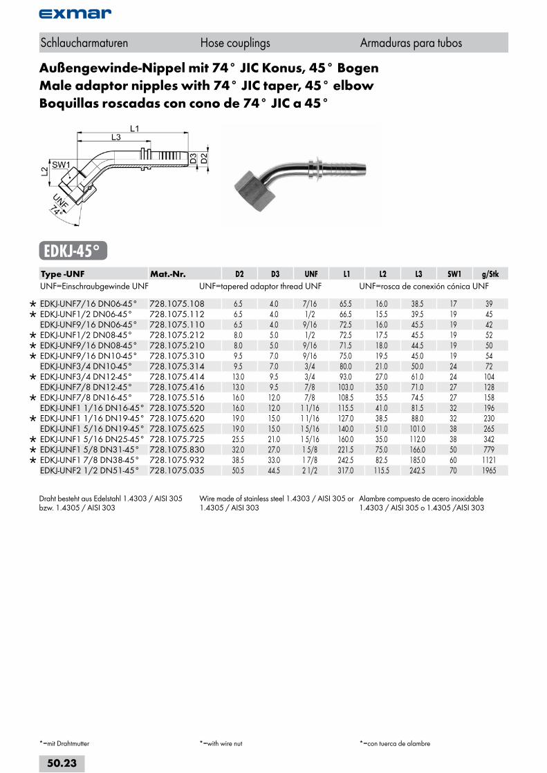
Außengewinde-Nippel mit 74° JIC Konus, 45° BogenMale adaptor nipples with 74° JIC taper, 45° elbowBoquillas roscadas con cono de 74° JIC a 45°
EDKJ-45°Type -UNF Mat.-Nr. D2 D3 UNF L1 L2 L3 SW1 g/StkUNF=Einschraubgewinde UNF UNF=tapered adaptor thread UNF UNF=rosca de conexión cónica UNF
EDKJ-UNF7/16 DN06-45° 728.1075.108 6.5 4.0 7/16 65.5 16.0 38.5 17 39 EDKJ-UNF1/2 DN06-45° 728.1075.112 6.5 4.0 1/2 66.5 15.5 39.5 19 45 EDKJ-UNF9/16 DN06-45° 728.1075.110 6.5 4.0 9/16 72.5 16.0 45.5 19 42
EDKJ-UNF1/2 DN08-45° 728.1075.212 8.0 5.0 1/2 72.5 17.5 45.5 19 52 EDKJ-UNF9/16 DN08-45° 728.1075.210 8.0 5.0 9/16 71.5 18.0 44.5 19 50 EDKJ-UNF9/16 DN10-45° 728.1075.310 9.5 7.0 9/16 75.0 19.5 45.0 19 54 EDKJ-UNF3/4 DN10-45° 728.1075.314 9.5 7.0 3/4 80.0 21.0 50.0 24 72
EDKJ-UNF3/4 DN12-45° 728.1075.414 13.0 9.5 3/4 93.0 27.0 61.0 24 104 EDKJ-UNF7/8 DN12-45° 728.1075.416 13.0 9.5 7/8 103.0 35.0 71.0 27 128
EDKJ-UNF7/8 DN16-45° 728.1075.516 16.0 12.0 7/8 108.5 35.5 74.5 27 158 EDKJ-UNF1 1/16 DN16-45° 728.1075.520 16.0 12.0 1 1/16 115.5 41.0 81.5 32 196
EDKJ-UNF1 1/16 DN19-45° 728.1075.620 19.0 15.0 1 1/16 127.0 38.5 88.0 32 230 EDKJ-UNF1 5/16 DN19-45° 728.1075.625 19.0 15.0 1 5/16 140.0 51.0 101.0 38 265
EDKJ-UNF1 5/16 DN25-45° 728.1075.725 25.5 21.0 1 5/16 160.0 35.0 112.0 38 342 EDKJ-UNF1 5/8 DN31-45° 728.1075.830 32.0 27.0 1 5/8 221.5 75.0 166.0 50 779 EDKJ-UNF1 7/8 DN38-45° 728.1075.932 38.5 33.0 1 7/8 242.5 82.5 185.0 60 1121 EDKJ-UNF2 1/2 DN51-45° 728.1075.035 50.5 44.5 2 1/2 317.0 115.5 242.5 70 1965
Draht besteht aus Edelstahl 1.4303 / AISI 305 bzw. 1.4305 / AISI 303
Wire made of stainless steel 1.4303 / AISI 305 or 1.4305 / AISI 303
Alambre compuesto de acero inoxidable 1.4303 / AISI 305 o 1.4305 /AISI 303
Schlaucharmaturen Hose couplings Armaduras para tubos
*=mit Drahtmutter *=with wire nut *=con tuerca de alambre
50.23
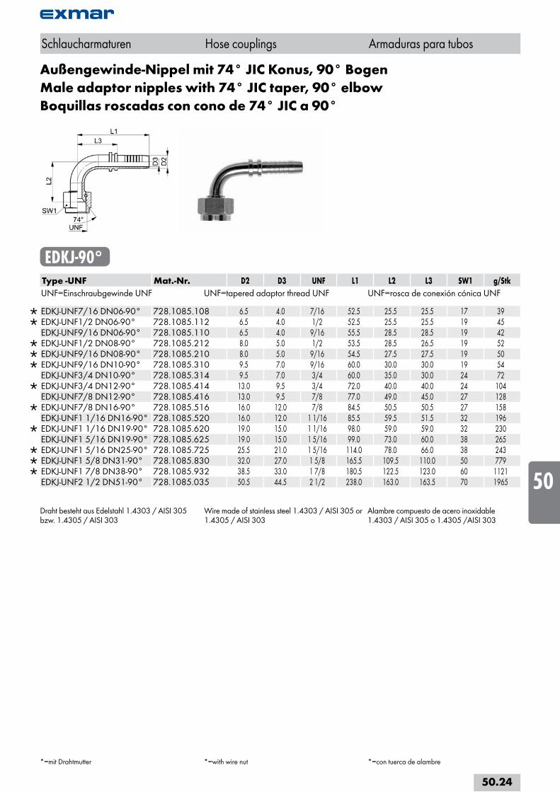
Außengewinde-Nippel mit 74° JIC Konus, 90° BogenMale adaptor nipples with 74° JIC taper, 90° elbowBoquillas roscadas con cono de 74° JIC a 90°
EDKJ-90°Type -UNF Mat.-Nr. D2 D3 UNF L1 L2 L3 SW1 g/StkUNF=Einschraubgewinde UNF UNF=tapered adaptor thread UNF UNF=rosca de conexión cónica UNF
EDKJ-UNF7/16 DN06-90° 728.1085.108 6.5 4.0 7/16 52.5 25.5 25.5 17 39 EDKJ-UNF1/2 DN06-90° 728.1085.112 6.5 4.0 1/2 52.5 25.5 25.5 19 45 EDKJ-UNF9/16 DN06-90° 728.1085.110 6.5 4.0 9/16 55.5 28.5 28.5 19 42
EDKJ-UNF1/2 DN08-90° 728.1085.212 8.0 5.0 1/2 53.5 28.5 26.5 19 52 EDKJ-UNF9/16 DN08-90° 728.1085.210 8.0 5.0 9/16 54.5 27.5 27.5 19 50 EDKJ-UNF9/16 DN10-90° 728.1085.310 9.5 7.0 9/16 60.0 30.0 30.0 19 54 EDKJ-UNF3/4 DN10-90° 728.1085.314 9.5 7.0 3/4 60.0 35.0 30.0 24 72
EDKJ-UNF3/4 DN12-90° 728.1085.414 13.0 9.5 3/4 72.0 40.0 40.0 24 104 EDKJ-UNF7/8 DN12-90° 728.1085.416 13.0 9.5 7/8 77.0 49.0 45.0 27 128
EDKJ-UNF7/8 DN16-90° 728.1085.516 16.0 12.0 7/8 84.5 50.5 50.5 27 158 EDKJ-UNF1 1/16 DN16-90° 728.1085.520 16.0 12.0 1 1/16 85.5 59.5 51.5 32 196
EDKJ-UNF1 1/16 DN19-90° 728.1085.620 19.0 15.0 1 1/16 98.0 59.0 59.0 32 230 EDKJ-UNF1 5/16 DN19-90° 728.1085.625 19.0 15.0 1 5/16 99.0 73.0 60.0 38 265
EDKJ-UNF1 5/16 DN25-90° 728.1085.725 25.5 21.0 1 5/16 114.0 78.0 66.0 38 243 EDKJ-UNF1 5/8 DN31-90° 728.1085.830 32.0 27.0 1 5/8 165.5 109.5 110.0 50 779 EDKJ-UNF1 7/8 DN38-90° 728.1085.932 38.5 33.0 1 7/8 180.5 122.5 123.0 60 1121 EDKJ-UNF2 1/2 DN51-90° 728.1085.035 50.5 44.5 2 1/2 238.0 163.0 163.5 70 1965
Draht besteht aus Edelstahl 1.4303 / AISI 305 bzw. 1.4305 / AISI 303
Wire made of stainless steel 1.4303 / AISI 305 or 1.4305 / AISI 303
Alambre compuesto de acero inoxidable 1.4303 / AISI 305 o 1.4305 /AISI 303
Schlaucharmaturen Hose couplings Armaduras para tubos
*=mit Drahtmutter *=with wire nut *=con tuerca de alambre
50.24
i
s
10
20
30
40
50
60
70
80
a
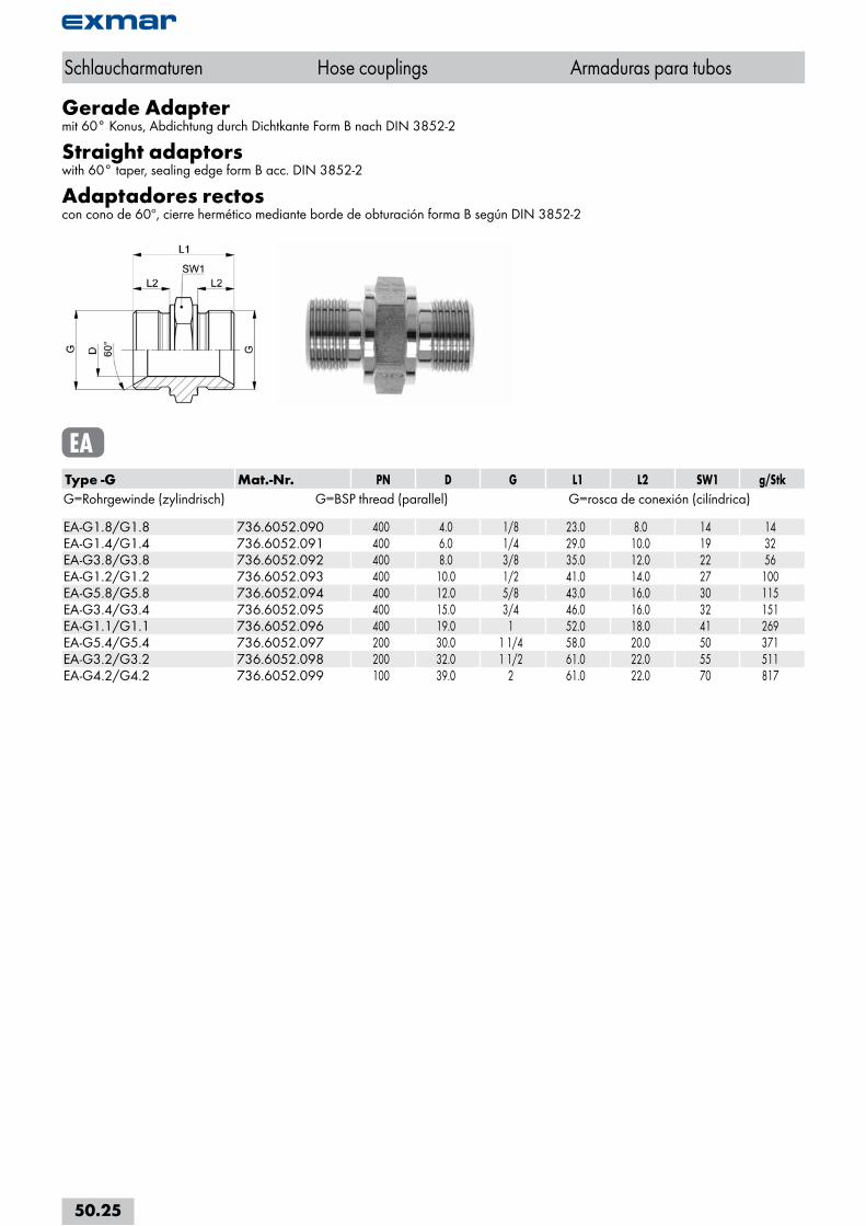
Gerade Adaptermit 60° Konus, Abdichtung durch Dichtkante Form B nach DIN 3852-2
Straight adaptorswith 60° taper, sealing edge form B acc. DIN 3852-2
Adaptadores rectoscon cono de 60º, cierre hermético mediante borde de obturación forma B según DIN 3852-2
EAType -G Mat.-Nr. PN D G L1 L2 SW1 g/StkG=Rohrgewinde (zylindrisch) G=BSP thread (parallel) G=rosca de conexión (cilíndrica) EA-G1.8/G1.8 736.6052.090 400 4.0 1/8 23.0 8.0 14 14EA-G1.4/G1.4 736.6052.091 400 6.0 1/4 29.0 10.0 19 32EA-G3.8/G3.8 736.6052.092 400 8.0 3/8 35.0 12.0 22 56EA-G1.2/G1.2 736.6052.093 400 10.0 1/2 41.0 14.0 27 100EA-G5.8/G5.8 736.6052.094 400 12.0 5/8 43.0 16.0 30 115EA-G3.4/G3.4 736.6052.095 400 15.0 3/4 46.0 16.0 32 151EA-G1.1/G1.1 736.6052.096 400 19.0 1 52.0 18.0 41 269EA-G5.4/G5.4 736.6052.097 200 30.0 1 1/4 58.0 20.0 50 371EA-G3.2/G3.2 736.6052.098 200 32.0 1 1/2 61.0 22.0 55 511EA-G4.2/G4.2 736.6052.099 100 39.0 2 61.0 22.0 70 817
Schlaucharmaturen Hose couplings Armaduras para tubos
50.25
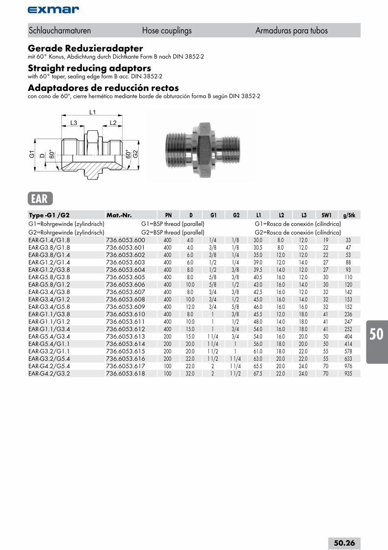
Gerade Reduzieradaptermit 60° Konus, Abdichtung durch Dichtkante Form B nach DIN 3852-2
Straight reducing adaptorswith 60° taper, sealing edge form B acc. DIN 3852-2
Adaptadores de reducción rectoscon cono de 60º, cierre hermético mediante borde de obturación forma B según DIN 3852-2
EARType -G1 /G2 Mat.-Nr. PN D G1 G2 L1 L2 L3 SW1 g/StkG1=Rohrgewinde (zylindrisch) G1=BSP thread (parallel) G1=Rosca de conexión (cilíndrica)G2=Rohrgewinde (zylindrisch) G2=BSP thread (parallel) G2=Rosca de conexión (cilíndrica)EAR-G1.4/G1.8 736.6053.600 400 4.0 1/4 1/8 30.0 8.0 12.0 19 33EAR-G3.8/G1.8 736.6053.601 400 4.0 3/8 1/8 30.5 8.0 12.0 22 47EAR-G3.8/G1.4 736.6053.602 400 6.0 3/8 1/4 35.0 12.0 12.0 22 53EAR-G1.2/G1.4 736.6053.603 400 6.0 1/2 1/4 39.0 12.0 14.0 27 88EAR-G1.2/G3.8 736.6053.604 400 8.0 1/2 3/8 39.5 14.0 12.0 27 93EAR-G5.8/G3.8 736.6053.605 400 8.0 5/8 3/8 40.5 16.0 12.0 30 110EAR-G5.8/G1.2 736.6053.606 400 10.0 5/8 1/2 43.0 16.0 14.0 30 120EAR-G3.4/G3.8 736.6053.607 400 8.0 3/4 3/8 42.5 16.0 12.0 32 142EAR-G3.4/G1.2 736.6053.608 400 10.0 3/4 1/2 45.0 16.0 14.0 32 153EAR-G3.4/G5.8 736.6053.609 400 12.0 3/4 5/8 46.0 16.0 16.0 32 152EAR-G1.1/G3.8 736.6053.610 400 8.0 1 3/8 45.5 12.0 18.0 41 236EAR-G1.1/G1.2 736.6053.611 400 10.0 1 1/2 48.0 14.0 18.0 41 247EAR-G1.1/G3.4 736.6053.612 400 15.0 1 3/4 54.0 16.0 18.0 41 252EAR-G5.4/G3.4 736.6053.613 200 15.0 1 1/4 3/4 54.0 16.0 20.0 50 404EAR-G5.4/G1.1 736.6053.614 200 20.0 1 1/4 1 56.0 18.0 20.0 50 414EAR-G3.2/G1.1 736.6053.615 200 20.0 1 1/2 1 61.0 18.0 22.0 55 578EAR-G3.2/G5.4 736.6053.616 200 22.0 1 1/2 1 1/4 63.0 20.0 22.0 55 633EAR-G4.2/G5.4 736.6053.617 100 22.0 2 1 1/4 65.5 20.0 24.0 70 976EAR-G4.2/G3.2 736.6053.618 100 32.0 2 1 1/2 67.5 22.0 24.0 70 935
Schlaucharmaturen Hose couplings Armaduras para tubos
50.26
i
s
10
20
30
40
50
60
70
80
a
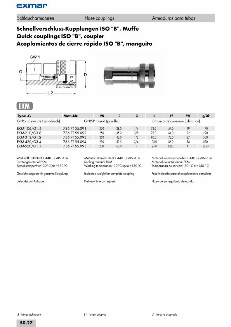
Schnellverschluss-Kupplungen ISO "B", MuffeQuick couplings ISO "B", couplerAcoplamientos de cierre rápido ISO "B", manguito
EKMType -G Mat.-Nr. PN D G L1 L2 SW1 g/StkG=Rohrgewinde (zylindrisch) G=BSP thread (parallel) G=rosca de conexión (cilíndrica) EKM-106/G1.4 736.7155.091 300 28.0 1/4 72.0 57.0 19 170EKM-210/G3.8 736.7155.092 250 35.0 3/8 78.0 64.0 22 290EKM-313/G1.2 736.7155.093 250 42.0 1/2 90.0 72.0 27 500EKM-420/G3.4 736.7155.094 250 51.5 3/4 105.0 86.0 34 850EKM-520/G1.1 736.7155.095 200 60.0 1 125.0 102.0 41 1250
Werkstoff: Edelstahl 1.4401 / AISI 316Dichtungsmaterial FKMBetriebstemperatur: -30°C bis +150°C
Gewichtsangabe für gesamte Kupplung
Lieferfrist auf Anfrage.
Material: stainless steel 1.4401 / AISI 316Sealing material FKMWorking temperature: -30°C up to +150°C
Indicated weight for complete coupling
Delivery time on request.
Material: acero inoxidable 1.4401 / AISI 316Material de junta tórica: FKMTemperatura de servicio: -30 °C a +150 °C
Peso indicado para el acoplamiento completa
Plazo de entrega bajo demanda.
Schlaucharmaturen Hose couplings Armaduras para tubos
L1 - Länge gekoppelt L1 - length coupled L1 - largura acoplada
50.27
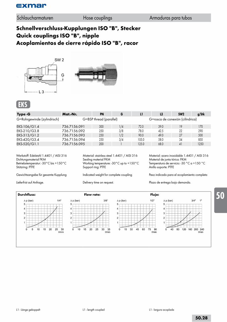
Schnellverschluss-Kupplungen ISO "B", SteckerQuick couplings ISO "B", nippleAcoplamientos de cierre rápido ISO "B", racor
EKSType -G Mat.-Nr. PN G L1 L3 SW2 g/StkG=Rohrgewinde (zylindrisch) G=BSP thread (parallel) G=rosca de conexión (cilíndrica) EKS-106/G1.4 736.7156.091 300 1/4 72.0 39.0 19 170EKS-210/G3.8 736.7156.092 250 3/8 78.0 42.5 22 290EKS-313/G1.2 736.7156.093 250 1/2 90.0 49.0 27 500EKS-420/G3.4 736.7156.094 250 3/4 105.0 58.0 34 850EKS-520/G1.1 736.7156.095 200 1 125.0 68.0 41 1250
Werkstoff: Edelstahl 1.4401 / AISI 316Dichtungsmaterial FKMBetriebstemperatur: -30°C bis +150°C Stützring: PTFE
Gewichtsangabe für gesamte Kupplung
Lieferfrist auf Anfrage.
Material: stainless steel 1.4401 / AISI 316Sealing material FKMWorking temperature: -30°C up to +150°CSupport ring: PTFE
Indicated weight for complete coupling
Delivery time on request.
Material: acero inoxidable 1.4401 / AISI 316Material de junta tórica: FKMTemperatura de servicio: -30 °C a +150 °CAnillo soporte: PTFE
Peso indicado para el acoplamiento completa
Plazo de entrega bajo demanda.
Durchfluss: Flow rate: Flujo:
Schlaucharmaturen Hose couplings Armaduras para tubos
L1 - Länge gekoppelt L1 - length coupled L1 - largura acoplada
50.28
i
s
10
20
30
40
50
60
70
80
a
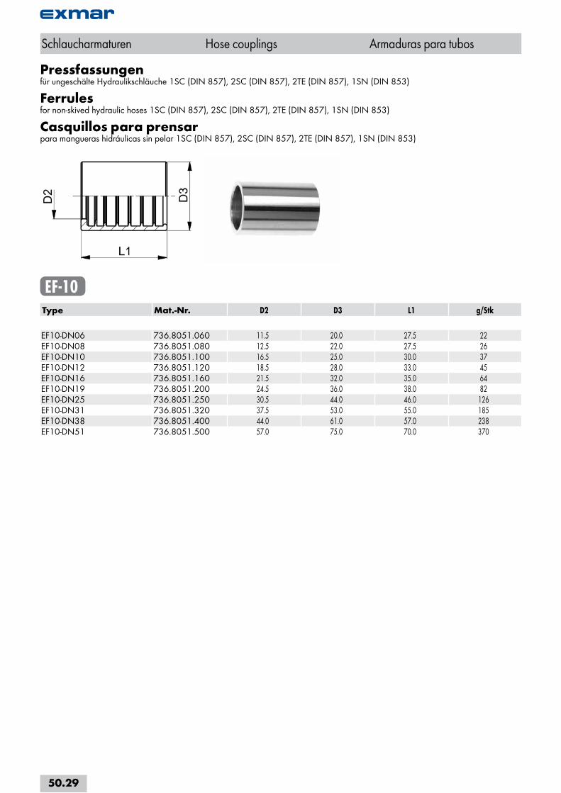
Pressfassungenfür ungeschälte Hydraulikschläuche 1SC (DIN 857), 2SC (DIN 857), 2TE (DIN 857), 1SN (DIN 853)
Ferrulesfor non-skived hydraulic hoses 1SC (DIN 857), 2SC (DIN 857), 2TE (DIN 857), 1SN (DIN 853)
Casquillos para prensarpara mangueras hidráulicas sin pelar 1SC (DIN 857), 2SC (DIN 857), 2TE (DIN 857), 1SN (DIN 853)
EF-10Type Mat.-Nr. D2 D3 L1 g/Stk EF10-DN06 736.8051.060 11.5 20.0 27.5 22EF10-DN08 736.8051.080 12.5 22.0 27.5 26EF10-DN10 736.8051.100 16.5 25.0 30.0 37EF10-DN12 736.8051.120 18.5 28.0 33.0 45EF10-DN16 736.8051.160 21.5 32.0 35.0 64EF10-DN19 736.8051.200 24.5 36.0 38.0 82EF10-DN25 736.8051.250 30.5 44.0 46.0 126EF10-DN31 736.8051.320 37.5 53.0 55.0 185EF10-DN38 736.8051.400 44.0 61.0 57.0 238EF10-DN51 736.8051.500 57.0 75.0 70.0 370
Schlaucharmaturen Hose couplings Armaduras para tubos
50.29
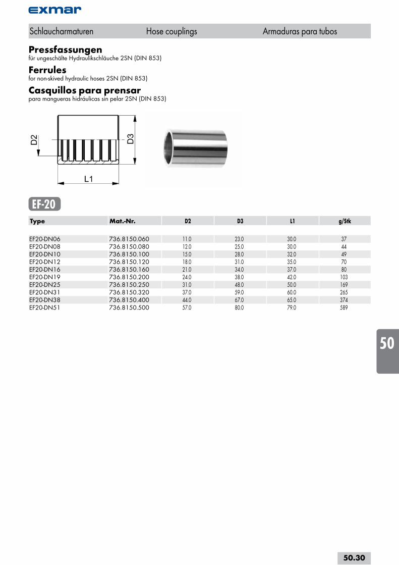
Pressfassungenfür ungeschälte Hydraulikschläuche 2SN (DIN 853)
Ferrulesfor non-skived hydraulic hoses 2SN (DIN 853)
Casquillos para prensarpara mangueras hidráulicas sin pelar 2SN (DIN 853)
EF-20Type Mat.-Nr. D2 D3 L1 g/Stk EF20-DN06 736.8150.060 11.0 23.0 30.0 37EF20-DN08 736.8150.080 12.0 25.0 30.0 44EF20-DN10 736.8150.100 15.0 28.0 32.0 49EF20-DN12 736.8150.120 18.0 31.0 35.0 70EF20-DN16 736.8150.160 21.0 34.0 37.0 80EF20-DN19 736.8150.200 24.0 38.0 42.0 103EF20-DN25 736.8150.250 31.0 48.0 50.0 169EF20-DN31 736.8150.320 37.0 59.0 60.0 265EF20-DN38 736.8150.400 44.0 67.0 65.0 374EF20-DN51 736.8150.500 57.0 80.0 79.0 589
Schlaucharmaturen Hose couplings Armaduras para tubos
50.30
i
s
10
20
30
40
50
60
70
80
a
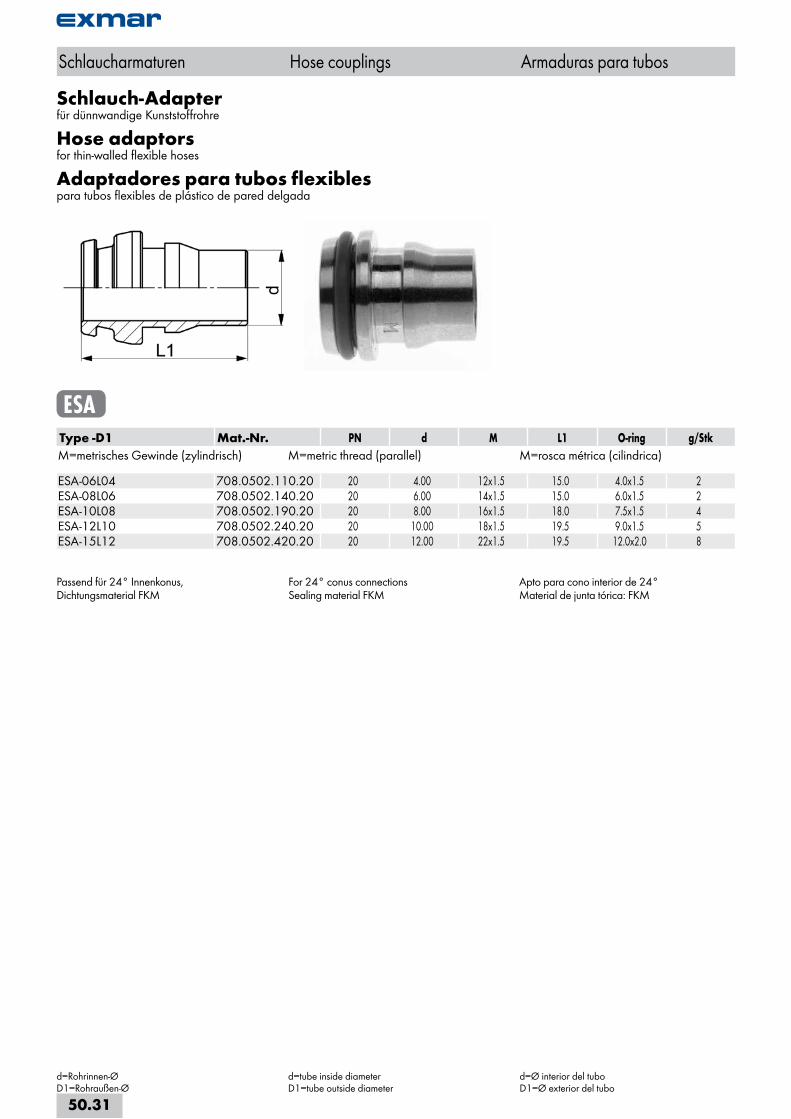
Schlauch-Adapterfür dünnwandige Kunststoffrohre
Hose adaptorsfor thin-walled flexible hoses
Adaptadores para tubos flexiblespara tubos flexibles de plástico de pared delgada
ESAType -D1 Mat.-Nr. PN d M L1 O-ring g/StkM=metrisches Gewinde (zylindrisch) M=metric thread (parallel) M=rosca métrica (cilindrica) ESA-06L04 708.0502.110.20 20 4.00 12x1.5 15.0 4.0x1.5 2ESA-08L06 708.0502.140.20 20 6.00 14x1.5 15.0 6.0x1.5 2ESA-10L08 708.0502.190.20 20 8.00 16x1.5 18.0 7.5x1.5 4ESA-12L10 708.0502.240.20 20 10.00 18x1.5 19.5 9.0x1.5 5ESA-15L12 708.0502.420.20 20 12.00 22x1.5 19.5 12.0x2.0 8
Passend für 24° Innenkonus,Dichtungsmaterial FKM
For 24° conus connectionsSealing material FKM
Apto para cono interior de 24°Material de junta tórica: FKM
Schlaucharmaturen Hose couplings Armaduras para tubos
d=Rohrinnen-ØD1=Rohraußen-Ø
d=tube inside diameterD1=tube outside diameter
d=Ø interior del tuboD1=Ø exterior del tubo
50.31
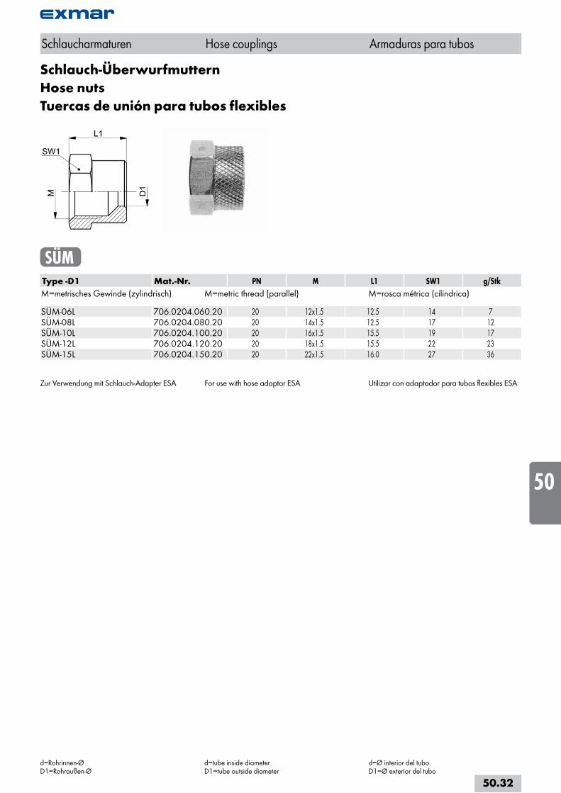
Schlauch-ÜberwurfmutternHose nutsTuercas de unión para tubos flexibles
SÜMType -D1 Mat.-Nr. PN M L1 SW1 g/StkM=metrisches Gewinde (zylindrisch) M=metric thread (parallel) M=rosca métrica (cilindrica) SÜM-06L 706.0204.060.20 20 12x1.5 12.5 14 7SÜM-08L 706.0204.080.20 20 14x1.5 12.5 17 12SÜM-10L 706.0204.100.20 20 16x1.5 15.5 19 17SÜM-12L 706.0204.120.20 20 18x1.5 15.5 22 23SÜM-15L 706.0204.150.20 20 22x1.5 16.0 27 36
Zur Verwendung mit Schlauch-Adapter ESA For use with hose adaptor ESA Utilizar con adaptador para tubos flexibles ESA
Schlaucharmaturen Hose couplings Armaduras para tubos
d=Rohrinnen-ØD1=Rohraußen-Ø
d=tube inside diameterD1=tube outside diameter
d=Ø interior del tuboD1=Ø exterior del tubo
50.32
i
s
10
20
30
40
50
60
70
80
a
Schlaucharmaturen Hose couplings Armaduras para tubos
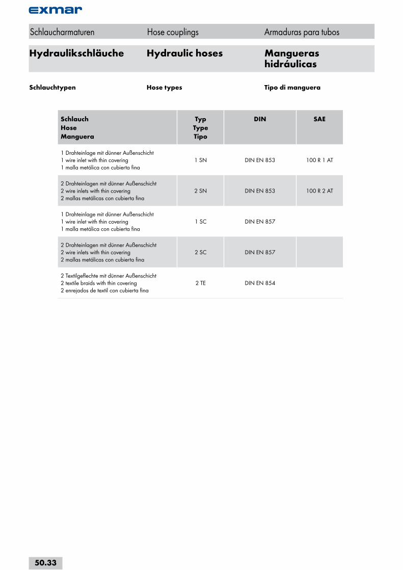
Hydraulikschläuche Hydraulic hoses Mangueras hidráulicas
Schlauch HoseManguera
Typ TypeTipo
DIN SAE
1 Drahteinlage mit dünner Außenschicht 1 wire inlet with thin covering 1 malla metálica con cubierta fina
1 SN DIN EN 853 100 R 1 AT
2 Drahteinlagen mit dünner Außenschicht 2 wire inlets with thin covering 2 mallas metálicas con cubierta fina
2 SN DIN EN 853 100 R 2 AT
1 Drahteinlage mit dünner Außenschicht1 wire inlet with thin covering1 malla metálica con cubierta fina
1 SC DIN EN 857
2 Drahteinlagen mit dünner Außenschicht2 wire inlets with thin covering2 mallas metálicas con cubierta fina
2 SC DIN EN 857
2 Textilgeflechte mit dünner Außenschicht2 textile braids with thin covering2 enrejados de textil con cubierta fina
2 TE DIN EN 854
Schlauchtypen Hose types Tipo di manguera
50.33
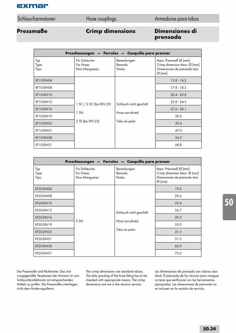
Pressmaße Crimp dimensions Dimensiones di prensado
Schlaucharmaturen Hose couplings Armaduras para tubos
Pressfassungen — Ferrules — Casquillo para prensar
TypTypeTipo
Für SchäucheFor HosesPara Mangueras
BemerkungenRemarksNotas
theor. Pressmaß Ø [mm]Crimp dimension theor. Ø [mm]Dimensiones de prensado teór. Ø [mm]
EF10-DN06
1 SC / 2 SC (bis DN 25)
1 SN
2 TE (bis DN 25)
Schlauch nicht geschält
Hose non-skived
Tubo sin pelar
15.8 - 16.2
EF10-DN08 17.8 - 18.2
EF10-DN10 20.4 - 20.8
EF10-DN12 23.8 - 24.3
EF10-DN16 27.6 - 28.1
EF10-DN19 30.5
EF10-DN25 39.4
EF10-DN31 47.0
EF10-DN38 54.5
EF10-DN51 68.8
Pressfassungen — Ferrules — Casquillo para prensar
TypTypeTipo
Für SchläucheFor HosesPara Mangueras
BemerkungenRemarksNotas
theor. Pressmaß Ø [mm]Crimp dimension theor. Ø [mm]Dimensiones de prensado teór. Ø [mm]
EF20-DN06
2 SN
Schlauch nicht geschält
Hose non-skived
Tubo sin pelar
19.0
EF20-DN08 20.6
EF20-DN10 23.4
EF20-DN12 26.7
EF20-DN16 29.5
EF20-DN19 33.0
EF20-DN25 41.5
EF20-DN31 51.3
EF20-DN38 60.5
EF20-DN51 73.5
Die Pressmaße sind Richtwerte. Das ord-nungsgemäße Verpressen der Armatur ist vom Schlauchkonfektionär mit entsprechenden Mitteln zu prüfen. Die Pressmaße unterliegen nicht dem Änderungsdienst.
The crimp dimensions are standard values. The duly grouting of the hose fitting has to be checked with appropriate means. The crimp dimensions are not in the revision service.
Las dimensiones de prensado son valores stan-dard. El prensado de los rácores para mangue-ra tiene que verificarse con las herramientas apropiadas. Las dimensiones de prensado no se incluyen en la revisión de servicio.
50.34
i
s
10
20
30
40
50
60
70
80
a
Hinweise zur Verle-gung von Schlauch-leitungen
Information on instal-ling hose lines
Información de la in-stalación de mangueras
1. Grundsätzliches
Eine Schlauchleitung darf niemals auf Torsion beansprucht werden; sie darf schon beim Einbau nicht verdreht werden. Unter Belastung kann sich eine Schlauchleitung in der Länge ändern. Eine Verkürzung bedeutet zusätzliche Zugspannung des Schlauches, deshalb leicht durchhängen lassen.
Überwurfmuttern nur soweit anziehen, bis der Anschluss dicht ist. Weiteres Anziehen verbes-sert die Dichtheit nicht, sondern beschädigt den Anschluss.
2. Gekrümmter Einbau
Bei gekrümmtem Einbau ist auf den zulässigen Biegeradius zu achten. Scharfe Knicke sind zu vermeiden. Bei der Längenberechnung einer gekrümmt verlegten Schlauchleitung ist zu beachten, dass die Anschlussarmaturen nicht flexibel sind. Die richtige Bemessung der freien Schlauchlänge zwischen den Armaturen ist daher wesentlich.
Für einen zweckmäßigen Einbau von Schlauch-leitungen stehen Rohrkrümmer zur Verfügung. Der Radius dieser Verschraubung ist so klein, dass auch bei beengten Einbauverhältnissen eine richtige Verlegung der Schlauchleitung möglich ist.
Rohrkrümmer sind auch dort angebracht, wo die Anordnung der Anschlüsse einen "hän-genden" Bogen nicht zulässt und bei "stehen-dem" Bogen stets eine Knickgefahr hinter der Schlauchfassung besteht.
Erforderliche Halterungen in der richtigen Grö-ße verwenden. Der Schlauch darf nicht in der Halterung reiben, aber auch nicht gequetscht werden.
1. General
A hose line may never be subjected to torsion; i.e. it may not be twisted or contorted during installation. If strained, a hose line may change in length. A shortening of the line indicates tensile strain, which means it should be given additional slack.
Hose nuts should only be tightened up to the point of leak-tightness. Further tightening will not improve the leak-tightness of the connec-tion, but will damage it.
2. Curved installations
For installations which require bending, the permissible bending radius must be obser-ved. Sharp bends (kinks) in the line should be avoided. When calculating the length of an installation with bends, remember that the connection fittings are not flexible. It is therefore essential to accurately measure the free hose length between the fittings.
For convenient installation of hose lines, elbows are available. The radius of these connectors is so small that hose lines can be easily installed even in cramped situations.
Elbows are also useful where the arrangement does not permit a “hanging“ bend and where there is risk of buckling after the hose joint in “upright“ bends.
Supports, if required, should always be in the right dimension. The hose may neither rub against the support, nor be crushed by it.
1. Generalidades
Las tuberías flexibles no deben someterse nunca a esfuerzos de torsión y no deben torcerse durante el montaje. La longitud de una tubería flexible puede variar bajo carga. Una acortamiento representa una tensión de tracci-ón adicional del tubo flexible; por esta razón, dejar que cuelgue ligeramente.
Apretar las tuercas de unión solo hasta que la conexión sea estanca. Si se continúa apretan-do, no se mejora la estanquidad sino que se daña la conexión.
2. Montaje curvado
Para el montaje curvado debe respetarse el radio de curvatura (flexión) admisible. Evitar codos muy cerrados. A la hora de calcular la longitud de una tubería flexible con montaje curvado debe tenerse en cuenta que las valvulerías de la conexión no son flexibles. Por consiguiente, es fundamental dimensionar correctamente la longitud de tubo flexible libre entre las valvulerías..
Para el montaje correcto de tuberías flexibles existen tubos acodados. El radio de está unión roscada es tan pequeño que permite montar correctamente la tubería flexible incluso en condiciones de poco espacio.
Los tubos acodados son idóneos también cuan-do la situación de las conexiones no permite un codo "colgante" y hay peligro de que el tubo flexible se doble después del engaste si se utilizan codos "verticales".
Los soportes necesarios deben tener el tamaño adecuado. El tubo flexible no debe rozar den-tro del soporte y no quedar aplastado.
Schlaucharmaturen Hose couplings Armaduras para tubos
50.35
MontageanleitungSchlaucharmaturen
Assembly instructionsHose couplings
Instrucciones de montajeArmaduras para tubos flexibles
Anleitung zum Verpressen
• Wählen Sie alle Komponenten zur Ferti-gung der Schlauchleitung anhand unseres aktuellen Kataloges aus. Für die anschluss-seitigen Befestigungen stehen eine Reihe von Armaturen zur Verfügung.
Schlaucharmaturen müssen so ausgewählt werden, dass sie den zu erwartenden mechanischen, thermischen und chemischen Beanspruchungen standhalten.
• Schneiden Sie den ausgewählten Schlauch mit einem für den Schlauch vorgesehenem Schneideblatt senkrecht auf die gewünschte Länge.
• Setzen Sie die Pressfassung auf das Schlau-chende und schieben Sie die Pressfassung bis zum Anschlag über den Schlauch.
Schmieren Sie das schlauchseitige Fußteil des Nippels mit unserer ASW-Fettpaste, danach schieben Sie den Nippel in das Schlauch ende. Überprüfen Sie, ob die Einhängenut zwischen Fassung und Schlauchnippel richtig positioniert wurde.
• Zum Verpressen der Schlauchleitung wählen Sie bitte den Pressbackensatz, der dem angegebenen Pressmaß am nächsten liegt, aus. Bei z.B. einem Pressmaß von 23 mm ver-wenden Sie einen Backensatz von 22 mm.
• Um die Verpressung zu kontrollieren, prüfen Sie bitte mit Hilfe einer Schieblehre den Durchmesser der nun verpressten Fassung, mittig, in drei verschiedenen Positionen, ca. 120° voneinander versetzt. Diese drei Mes-sungen müssen dem Pressmaß entsprechen. Falls das Pressmaß nicht erreicht wurde, erhöhen Sie bitte die Einstellung Ihrer Ma-schine in 0.1 mm Schritten, um den korrekten Durchmesser zu erreichen.
Trotz empfohlenem Pressmaß ist es not-wendig, den Nippeleinfall zu messen. Der korrekte Nippeleinfall beträgt in der Regel, je Durchmesser, zwischen 0.1 und 0.5 mm.
• Eine zweifache Verpressung ist zu vermei-den, da dies die Lebenserwartung einer Schlauchleitung verringert. Benutzen Sie daher Pressbacken, die lang genug sind, um die Fassung komplett zu verpressen.
Pressfassungen dürfen nicht wiederverwen-det werden.
Pressing instructions
• Select all the components you need for your hose line from our current catalogue. We have a number of connection options to choose from.
Hose couplings must be selected according to the anticipated mechanical, thermal and chemical loads.
• Cut the selected hose to length, perpendicu-larly with a blade appropriate for hoses.
• Put the ferrule completely onto the hose end and slide it over the hose until the stop.
Grease the hose side part of the nipple with our ASW grease and then insert the nipple in the hose end. Check, that the groove between the ferrule and the hose nipple is positioned correctly.
• For crimping the hose line, please use the press jaws closest in dimension to the indi-cated crimp dimension. For example, for a crimp dimension of 23 mm, use 22 mm jaws.
• With the help of a slide gauge, check the diameter of the crimped ferrule, centred, in three different positions, approx. 120° apart. These three measurements must cor-respond to the crimp dimension. If the crimp dimension has not been realized, increase the setting on your machine in 0.1 mm incre-ments until the correct diameter is reached.
Despite the recommended crimp dimension, it is also necessary to measure the nipple deformation. The correct nipple deformation is generally, depending on the diameter, between 0.1 und 0.5 mm.
• A second crimping should be avoided since this reduces the life expectancy of a hose line. That is why press jaws should be used which are long enough to completely crimp the ferrule.
Ferrules may not be reused.
Instrucciones de prensado
• Elegir los componentes para la elaboración de tuberías flexibles en nuestro catálogo ac-tual. Para las fijaciones del lado de conexión puede elegirse entre varias valvulerías.
Elegir valvulerías para las tuberías flexibles que resistan las cargas mecánicas, térmicas y químicas esperadas.
• Cortar el tubo flexible elegido con una cuchilla adecuada, tronzando en perpendi-cular a la longitud deseada.
• Introducir el extremo del tubo completa-mente en el engaste y empuje el engaste de prensado sobre el tubo hasta llegar al tope.
Lubricar la pieza base de la boquilla del lado del tubo con nuestra grasa ASW e introducir la boquilla en el extremo del tubo. Comprobar si la ranura de enganche entre la valvulería y la boquilla del tubo flexible se ha situado correctamente.
• Para prensar la tubería flexible, elegir el juego de mordazas de prensado que mejor se ajuste a la medida de prensado especificada. Para una medida de prensado de 23 mm, por ejemplo, utilizar un juego de mordazas de 22 mm.
• Para verificar el prensado, utilizar un pie de rey para comprobar el diámetro del engaste prensado en el centro en tres posiciones diferentes, separadas aproximadamente 120º una de otra. Las tres mediciones deben corresponder a la medida de prensado. Si no se alcanza la medida de prensado, aumentar el ajuste de la maquina en pasos de 0.1 mm hasta conseguir el diámetro correcto.
Pese a la medida de prensado recomenda-da, es necesario medir el grado de compresi-ón de la boquilla. La compresión correcta de la boquilla suele ser de 0.1 a 0.5 mm, según diámetro.
• Evitar el prensado doble, pues acorta la esperanza de vida de la tubería flexible. Utilizar mordazas de prensado que sean su-ficientemente largas para prensar el engaste completo.
Los engastes de prensado no deben reutili-zarse.
Schlaucharmaturen Hose couplings Armaduras para tubos
50.36
i
s
10
20
30
40
50
60
70
80
a
MontageanleitungSchlaucharmaturen (Forts.)
Assembly instructionsHose couplings (cont.)
Instrucciones de montajeArmaduras para tubos flex. (cont.)
• Die Kennzeichnung muss dauerhaft und unter Berücksichtigung der jeweiligen Schlauch-normen erfolgen.
Anmerkung
• Sämtliche Fertigungstoleranzen sowie wei-tere technische Informationen zur Fertigung von Schlauchleitungen entnehmen Sie der DIN 20066.
• Wir weisen darauf hin, dass sich die genann-ten Angaben zur Fertigung von Schlauchlei-tungen nur auf die Verwendung von EXMAR-Produkten beziehen. Bei Verwen-dung anderer Fabrikate ist ein Kompatibili-tätstest anzufordern.
• Identification must be permanent and accor-ding to the respective hose standards.
Note
• All manufacturing tolerances, as well as additional technical data on the manufacture of hose lines can be found in DIN 20066.
• We would like to point out that the above information on assembling hose lines is only applicable to the use of EXMAR products. If other brands are used, a compatibility test should be requested.
• La identificación ha de ser indeleble y reali-zarse de acuerdo con las oportunas normas para tubos flexibles.
Nota
• Para conocer las tolerancias de fabricación y demás información técnica relativa a la elaboración de tuberías flexibles, consultar la norma DIN 20066.
• Hacemos hincapié en que los datos mencio-nados para la fabricación de tuberías flexi-bles se refieren solamente a la utilización de productos EXMAR. Para utilizar productos de otras marcas deberá solicitarse una prueba de compatibilidad.
Schlaucharmaturen Hose couplings Armaduras para tubos
50.37