Embed Size (px)
Citation preview
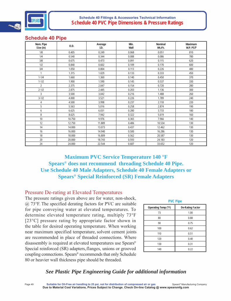
Schedule 40 Fittings & Accessories Technical Information Schedule 40 PVC Pipe Dimensions & Pressure Ratings
Page 49 Suitable for Oil-Free air handling to 25 psi, not for distribution of compressed air or gas Spears® Manufacturing CompanyDue to Material Cost Variations, Prices Subject to Change. Check On-line Catalog @ www.spearsmfg.com
Schedule 40 PipeNom. PipeSize (in) O.D. Average
I.D.Min. Wall
NominalWt./Ft.
MaximumW.P. PSI*
1/8 0.405 0.249 0.068 0.051 8101/4 0.540 0.344 0.088 0.086 7803/8 0.675 0.473 0.091 0.115 6201/2 0.840 0.602 0.109 0.170 6003/4 1.050 0.804 0.113 0.226 4801 1.315 1.029 0.133 0.333 450
1-1/4 1.660 1.360 0.140 0.450 3701-1/2 1.900 1.590 0.145 0.537 330
2 2.375 2.047 0.154 0.720 2802-1/2 2.875 2.445 0.203 1.136 300
3 3.500 3.042 0.216 1.488 2603-1/2 4.000 3.521 0.226 1.789 240
4 4.500 3.998 0.237 2.118 2205 5.563 5.016 0.258 2.874 1906 6.625 6.031 0.280 3.733 1808 8.625 7.942 0.322 5.619 160
10 10.750 9.976 0.365 7.966 14012 12.750 11.889 0.406 10.534 13014 14.000 13.073 0.437 12.462 13016 16.000 14.940 0.500 16.286 13018 18.000 16.809 0.562 20.587 13020 20.000 18.743 0.593 24.183 12024 24.000 22.544 0.687 33.652 120
Maximum PVC Service Temperature 140 °FSpears® does not recommend threading Schedule 40 Pipe.
Use Schedule 40 Male Adapters, Schedule 40 Female Adapters or Spears® Special Reinforced (SR) Female Adapters
PVC PipeOperating Temp (°F) De-Rating Factor
73 1.00
80 0.88
90 0.75
100 0.62
110 0.51
120 0.40
130 0.31
140 0.22
See Plastic Pipe Engineering Guide for additional information

Schedule 40 Fittings & Accessories Technical Information
Schedule 40 Product Overview
TECHNICAL INFORMATIONWEIGHTS & DIMENSIONS
PVC Schedule 40 Fittings & Accessories
Contact Spears® for any information not found.
Made in the U.S.A. Suitable for Oil-Free air handling to 25 psi, not for distribution of compressed air or gas Page 50Due to Material Cost Variations, Prices Subject to Change. Check On-line Catalog @ www.spearsmfg.com

Schedule 40 Fittings & Accessories Technical Information
Schedule 40 Product Overview
Page 51 Suitable for Oil-Free air handling to 25 psi, not for distribution of compressed air or gas Spears® Manufacturing CompanyDue to Material Cost Variations, Prices Subject to Change. Check On-line Catalog @ www.spearsmfg.com
Performance Engineered & Tested
SPEARS® Schedule 40 PVC fitting designs combine years of proven experience with computer generated stress analysis to yield the optimum physical structure and performance for each fitting. Material reinforcement is uniformly placed in stress concentration areas for substantially improved pressure handling capability. Resulting products are subjected to numerous verification tests to assure the very best PVC fittings available.
Full 1/4" Through 14" AvailabilitySpears® comprehensive line of PVC fittings offers a variety of injection molded configurations in Schedule 40 sizes 1/4"through 14" conforming to ASTM D 2466.
Exceptional Chemical & Corrosion ResistanceUnlike metal, PVC fittings never rust, scale, or pit, and will provide many years of maintenance-free service and extended system life.
High Temperature RatingsPVC thermoplastic can handle fl uids at service temperatures up to 140°F (60°C), allowing a wide range of process applications, including corrosive fl uids.
Lower Installation CostsSubstantially lower material costs than steel alloys or lined steel, combined with lighter weight and ease of installation, can reduce installation costs by as much as 60% over conventional metal systems.
Higher Flow CapacitySmooth interior walls result in lower pressure loss and higher volume than conventional metal fittings.
Additional Fabricated Configurationsthrough 36"Extra large, hard-to-find, and custom configurations are fabricated from NSF® Certified pipe. Fittings are engineered and tested to provide full pressure handling capabilities according to Spears® specifications.
PVC ValvesSPEARS® PVC Valve products are available for total system compatibility and uniformity.
Advanced Design Specialty FittingsSpears® wide range of innovative, improved products include numerous metal-to-plastic transition fittings and unions with Spears® patented special reinforced (SR) plastic threads.
1/2" Through 16" Industrial Pipe AvailabilitySpears® premium quality Industrial PVC pipe is offered in Schedule 40 White sizes 1/2" through 16".
Sample Engineering SpecificationsAll PVC Schedule 40 fi ttings shall be produced by Spears® Manufacturing Company from PVC Type I cell classifi cation 12454, conforming to ASTM D 1784. All injection molded PVC Schedule 40 fi ttings shall be Certifi ed for potable water service by NSF International and manufactured in strict compliance to ASTM D 2466. All fabricated fittings shall be produced in accordance with Spears® General Specifi cations for Fabricated Fittings.
Schedule 40 Fittings & Accessories Technical Information
Schedule 40 Product Overview
Made in the U.S.A. Suitable for Oil-Free air handling to 25 psi, not for distribution of compressed air or gas Page 52Due to Material Cost Variations, Prices Subject to Change. Check On-line Catalog @ www.spearsmfg.com
General InformationRecommendations For Installers And Users
Plastic piping systems should be ENGINEERED, INSTALLED and OPERATED in accordance with ESTABLISHED DESIGN AND ENGINEERING STANDARDS AND PROCEDURES for plastic piping systems. Suitability for the intended service application should bedetermined by the installer and/or user prior to installation of a plastic piping system. PRIOR TO ASSEMBLY, all piping system components should be inspected for damage or irregularities. Mating components should be checked to assure that tolerances and engagementsare compatible. Do not use any components that appear irregular or do not fit properly. Contact the appropriate manufacturer of the component product in question to determine usability. Consult all applicable codes and regulations for compliance prior to installation.
Solvent Weld Connections — Use quality solvent cements and primers formulated for the intended service application, pipe size andtype of joint. While the pipe and fitting materials may be compatible with the intended medium, the solvent cement may not be. Consult themanufacturers for suitability of use. Read and follow the cement and primer manufacturers’ applications and cure time instructions thoroughly.Be sure to use the correct size applicator.
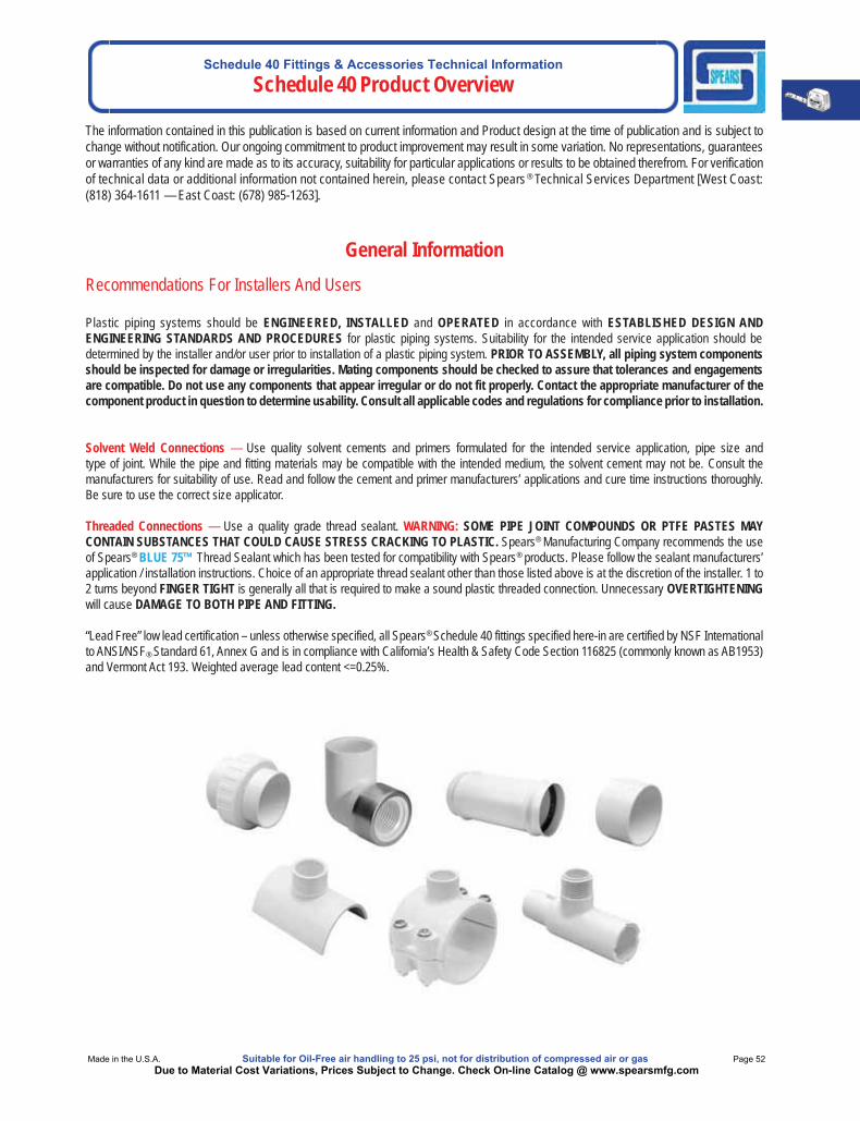
Threaded Connections — Use a quality grade thread sealant. WARNING: SOME PIPE JOINT COMPOUNDS OR PTFE PASTES MAYCONTAIN SUBSTANCES THAT COULD CAUSE STRESS CRACKING TO PLASTIC. Spears® Manufacturing Company recommends the useof Spears® BLUE 75™ Thread Sealant which has been tested for compatibility with Spears® products. Please follow the sealant manufacturers’ application / installation instructions. Choice of an appropriate thread sealant other than those listed above is at the discretion of the installer. 1 to 2 turns beyond FINGER TIGHT is generally all that is required to make a sound plastic threaded connection. Unnecessary OVERTIGHTENINGwill cause DAMAGE TO BOTH PIPE AND FITTING.
“Lead Free” low lead certification – unless otherwise specified, all Spears® Schedule 40 fittings specified here-in are certified by NSF Internationalto ANSI/NSF® Standard 61, Annex G and is in compliance with California’s Health & Safety Code Section 116825 (commonly known as AB1953)and Vermont Act 193. Weighted average lead content <=0.25%.
The information contained in this publication is based on current information and Product design at the time of publication and is subject tochange without notification. Our ongoing commitment to product improvement may result in some variation. No representations, guaranteesor warranties of any kind are made as to its accuracy, suitability for particular applications or results to be obtained therefrom. For verification of technical data or additional information not contained herein, please contact Spears ® Technical Services Department [West Coast: (818) 364-1611 — East Coast: (678) 985-1263].
Schedule 40 Fittings & Accessories Technical Information
Schedule 40 Product Overview
Page 53 Suitable for Oil-Free air handling to 25 psi, not for distribution of compressed air or gas Spears® Manufacturing CompanyDue to Material Cost Variations, Prices Subject to Change. Check On-line Catalog @ www.spearsmfg.com
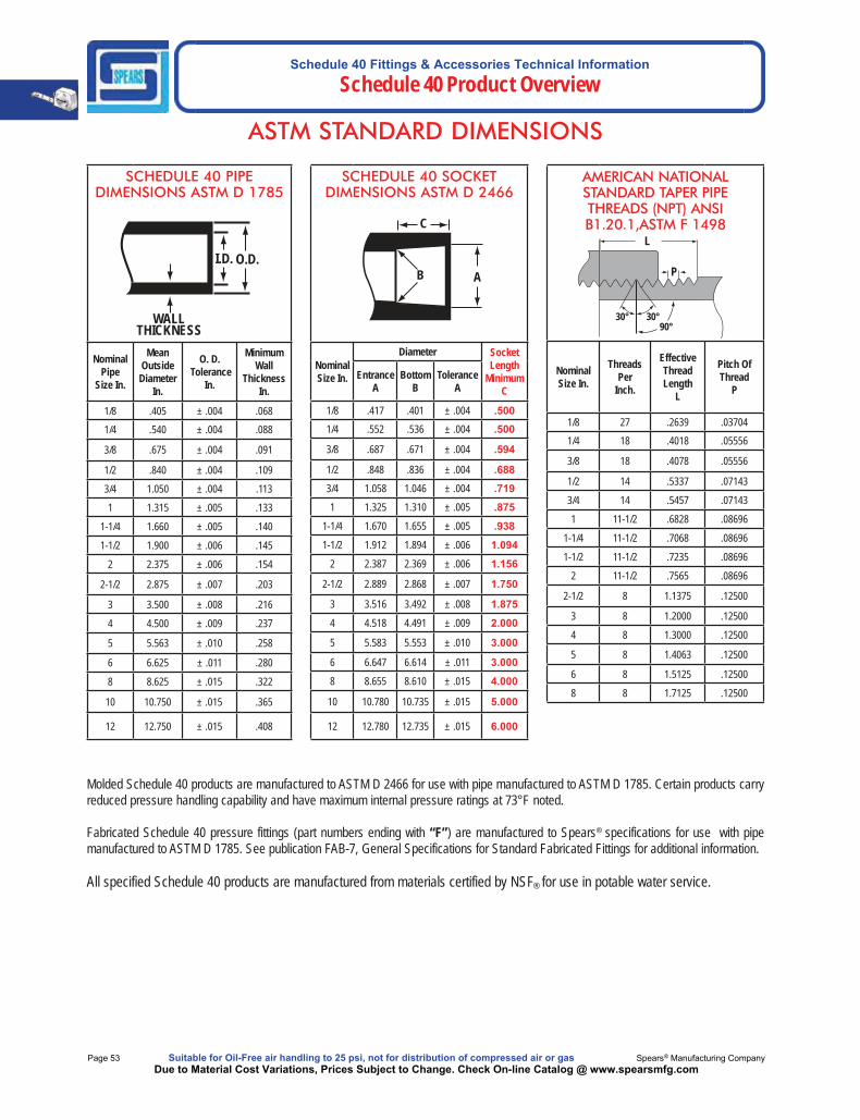
ASTM STANDARD DIMENSIONS
Molded Schedule 40 products are manufactured to ASTM D 2466 for use with pipe manufactured to ASTM D 1785. Certain products carryreduced pressure handling capability and have maximum internal pressure ratings at 73°F noted.
Fabricated Schedule 40 pressure fittings (part numbers ending with “F”) are manufactured to Spears® specifications for use with pipe manufactured to ASTM D 1785. See publication FAB-7, General Specifications for Standard Fabricated Fittings for additional information.
All specified Schedule 40 products are manufactured from materials certified by NSF® for use in potable water service.
SCHEDULE 40 PIPE DIMENSIONS ASTM D 1785
NominalPipe
Size In.
MeanOutsideDiameter
In.
O. D. Tolerance
In.
MinimumWall
ThicknessIn.
1/8 .405 ± .004 .0681/4 .540 ± .004 .088
3/8 .675 ± .004 .091
1/2 .840 ± .004 .109
3/4 1.050 ± .004 .113
1 1.315 ± .005 .133
1-1/4 1.660 ± .005 .140
1-1/2 1.900 ± .006 .145
2 2.375 ± .006 .154
2-1/2 2.875 ± .007 .203
3 3.500 ± .008 .216
4 4.500 ± .009 .237
5 5.563 ± .010 .258
6 6.625 ± .011 .280
8 8.625 ± .015 .322
10 10.750 ± .015 .365
12 12.750 ± .015 .408
WALLTHICKNESS
I.D. O.D.
SCHEDULE 40 SOCKET DIMENSIONS ASTM D 2466
NominalSize In.
Diameter SocketLength
MinimumC
EntranceA
BottomB
ToleranceA
1/8 .417 .401 ± .004 .5001/4 .552 .536 ± .004 .500
3/8 .687 .671 ± .004 .594
1/2 .848 .836 ± .004 .688
3/4 1.058 1.046 ± .004 .719
1 1.325 1.310 ± .005 .875
1-1/4 1.670 1.655 ± .005 .938
1-1/2 1.912 1.894 ± .006 1.094
2 2.387 2.369 ± .006 1.156
2-1/2 2.889 2.868 ± .007 1.750
3 3.516 3.492 ± .008 1.875
4 4.518 4.491 ± .009 2.000
5 5.583 5.553 ± .010 3.000
6 6.647 6.614 ± .011 3.000
8 8.655 8.610 ± .015 4.000
10 10.780 10.735 ± .015 5.000
12 12.780 12.735 ± .015 6.000
A
C
B
AMERICAN NATIONAL STANDARD TAPER PIPE THREADS (NPT) ANSI B1.20.1,ASTM F 1498
NominalSize In.
ThreadsPer
Inch.
EffectiveThreadLength
L
Pitch OfThread
P
1/8 27 .2639 .037041/4 18 .4018 .05556
3/8 18 .4078 .05556
1/2 14 .5337 .07143
3/4 14 .5457 .07143
1 11-1/2 .6828 .08696
1-1/4 11-1/2 .7068 .08696
1-1/2 11-1/2 .7235 .08696
2 11-1/2 .7565 .08696
2-1/2 8 1.1375 .12500
3 8 1.2000 .12500
4 8 1.3000 .12500
5 8 1.4063 .12500
6 8 1.5125 .12500
8 8 1.7125 .12500
L
P
90°30°30°
Schedule 40 Fittings & Accessories Technical InformationSchedule 40 Fittings Dimensions & Information
Made in the U.S.A. Suitable for Oil-Free air handling to 25 psi, not for distribution of compressed air or gas Page 54Due to Material Cost Variations, Prices Subject to Change. Check On-line Catalog @ www.spearsmfg.com
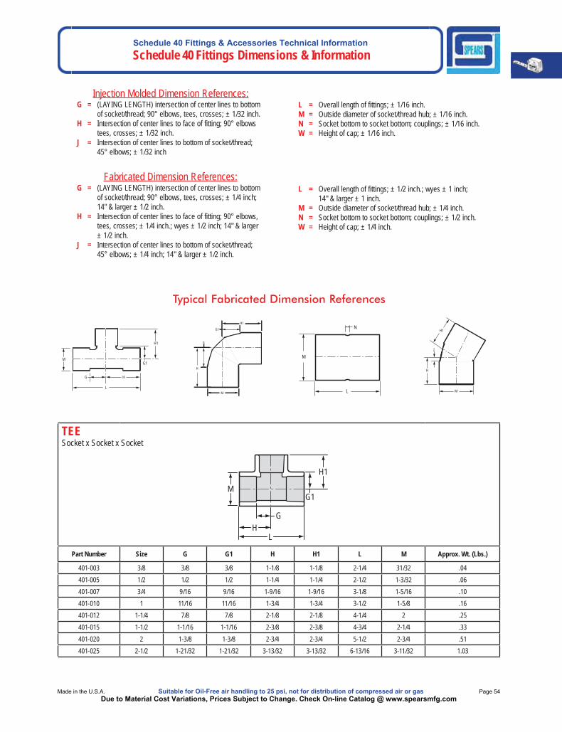
Injection Molded Dimension References:G = (LAYING LENGTH) intersection of center lines to bottom of socket/thread; 90° elbows, tees, crosses; ± 1/32 inch.H = Intersection of center lines to face of fitting; 90° elbows tees, crosses; ± 1/32 inch.J = Intersection of center lines to bottom of socket/thread; 45° elbows; ± 1/32 inch
Fabricated Dimension References:G = (LAYING LENGTH) intersection of center lines to bottom of socket/thread; 90° elbows, tees, crosses; ± 1/4 inch; 14" & larger ± 1/2 inch.H = Intersection of center lines to face of fitting; 90° elbows, tees, crosses; ± 1/4 inch.; wyes ± 1/2 inch; 14" & larger ± 1/2 inch.J = Intersection of center lines to bottom of socket/thread; 45° elbows; ± 1/4 inch; 14" & larger ± 1/2 inch.
L = Overall length of fittings; ± 1/16 inch.M = Outside diameter of socket/thread hub; ± 1/16 inch.N = Socket bottom to socket bottom; couplings; ± 1/16 inch.W = Height of cap; ± 1/16 inch.
L = Overall length of fittings; ± 1/2 inch.; wyes ± 1 inch; 14" & larger ± 1 inch.M = Outside diameter of socket/thread hub; ± 1/4 inch.N = Socket bottom to socket bottom; couplings; ± 1/2 inch.W = Height of cap; ± 1/4 inch.
Typical Fabricated Dimension References
M
H1
G1
L
H G
H1
G1
G
H
M L
N
M
M
H
J
H1
TEE Socket x Socket x Socket
M
H1
HG
L
G1
Part Number Size G G1 H H1 L M Approx. Wt. (Lbs.)
401-003 3/8 3/8 3/8 1-1/8 1-1/8 2-1/4 31/32 .04401-005 1/2 1/2 1/2 1-1/4 1-1/4 2-1/2 1-3/32 .06401-007 3/4 9/16 9/16 1-9/16 1-9/16 3-1/8 1-5/16 .10401-010 1 11/16 11/16 1-3/4 1-3/4 3-1/2 1-5/8 .16401-012 1-1/4 7/8 7/8 2-1/8 2-1/8 4-1/4 2 .25401-015 1-1/2 1-1/16 1-1/16 2-3/8 2-3/8 4-3/4 2-1/4 .33401-020 2 1-3/8 1-3/8 2-3/4 2-3/4 5-1/2 2-3/4 .51401-025 2-1/2 1-21/32 1-21/32 3-13/32 3-13/32 6-13/16 3-11/32 1.03
Schedule 40 Fittings & Accessories Technical Information Schedule 40 Fittings Dimensions & Information
Page 55 Suitable for Oil-Free air handling to 25 psi, not for distribution of compressed air or gas Spears® Manufacturing CompanyDue to Material Cost Variations, Prices Subject to Change. Check On-line Catalog @ www.spearsmfg.com
REDUCING TEE Socket x Socket x Socket
M
H1
H H2 G G2
L
G1 M2
M1
Part Number Size G G1 G2 H H1 H2 L M M1 M2Approx.
Wt. (Lbs.)
401-053 3/8x3/8x1/2 17/32 21/32 17/32 2-1/32 1-3/4 2-1/32 4-1/16 7/8 1-3/32 7/8 .08
401-074 1/2x1/2x3/4 9/16 9/16 9/16 1-5/16 1-9/16 1-5/16 2-5/8 1-1/16 1-9/32 1-1/16 .07401-075 1/2x1/2x1 25/32 17/32 25/32 1-17/32 1-11/16 1-17/32 3-1/16 1-1/16 1-5/8 1-1/16 .11401-094 3/4x1/2x1/2 17/32 21/32 17/32 1-17/32 1-13/32 1-9/32 2-13/16 1-5/16 1-3/32 1-3/32 .08401-095 3/4x1/2x3/4 13/16 11/16 5/8 1-13/16 1-15/32 1-3/8 3-3/16 1-5/16 1-5/16 1-1/16 .10401-101 3/4x3/4x1/2 17/32 5/8 17/32 1-7/16 1-3/8 1-7/16 2-29/32 1-5/16 1-1/8 1-5/16 .08
D401-101 3/4x3/4x1/2 9/16 19/32 17/32 1-17/32 1-27/32 1-17/32 3-1/16 1-5/16 1-3/32 1-5/16 .11401-102 3/4x3/4x1 23/32 5/8 23/32 1-21/32 1-21/32 1-21/32 3-5/16 1-5/16 1-5/8 1-5/16 .11401-122 1x1/2x1 23/32 23/32 27/32 1-25/32 1-25/32 1-19/32 3-7/16 1-5/8 1-5/8 1-3/32 .14
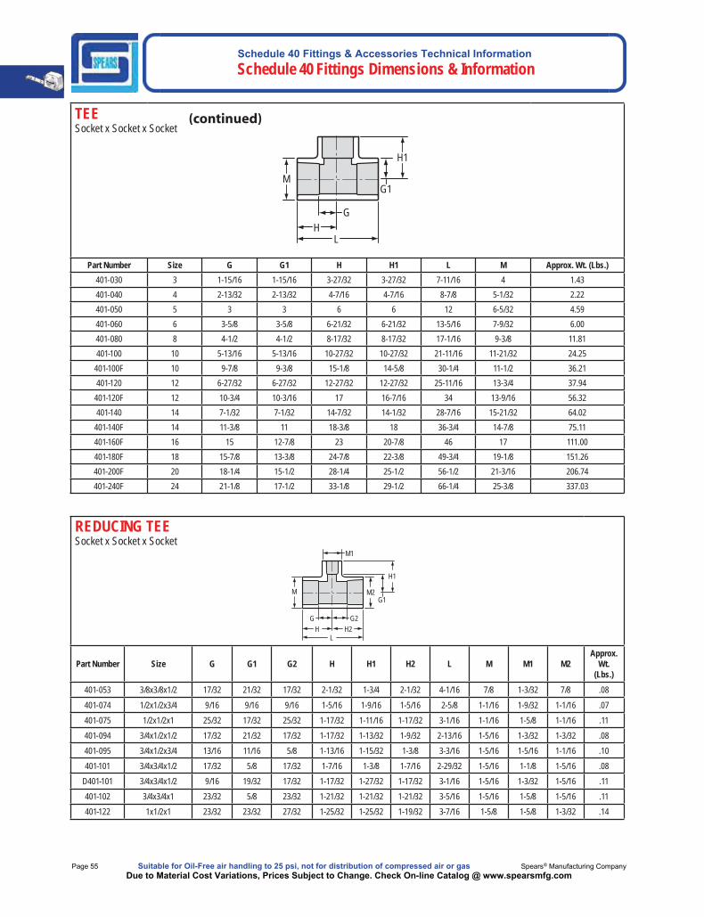
TEE Socket x Socket x Socket
M
H1
HG
L
G1
Part Number Size G G1 H H1 L M Approx. Wt. (Lbs.)401-030 3 1-15/16 1-15/16 3-27/32 3-27/32 7-11/16 4 1.43401-040 4 2-13/32 2-13/32 4-7/16 4-7/16 8-7/8 5-1/32 2.22401-050 5 3 3 6 6 12 6-5/32 4.59401-060 6 3-5/8 3-5/8 6-21/32 6-21/32 13-5/16 7-9/32 6.00401-080 8 4-1/2 4-1/2 8-17/32 8-17/32 17-1/16 9-3/8 11.81401-100 10 5-13/16 5-13/16 10-27/32 10-27/32 21-11/16 11-21/32 24.25
401-100F 10 9-7/8 9-3/8 15-1/8 14-5/8 30-1/4 11-1/2 36.21401-120 12 6-27/32 6-27/32 12-27/32 12-27/32 25-11/16 13-3/4 37.94
401-120F 12 10-3/4 10-3/16 17 16-7/16 34 13-9/16 56.32401-140 14 7-1/32 7-1/32 14-7/32 14-1/32 28-7/16 15-21/32 64.02
401-140F 14 11-3/8 11 18-3/8 18 36-3/4 14-7/8 75.11401-160F 16 15 12-7/8 23 20-7/8 46 17 111.00401-180F 18 15-7/8 13-3/8 24-7/8 22-3/8 49-3/4 19-1/8 151.26401-200F 20 18-1/4 15-1/2 28-1/4 25-1/2 56-1/2 21-3/16 206.74401-240F 24 21-1/8 17-1/2 33-1/8 29-1/2 66-1/4 25-3/8 337.03
Schedule 40 Fittings & Accessories Technical InformationSchedule 40 Fittings Dimensions & Information
Made in the U.S.A. Suitable for Oil-Free air handling to 25 psi, not for distribution of compressed air or gas Page 56Due to Material Cost Variations, Prices Subject to Change. Check On-line Catalog @ www.spearsmfg.com
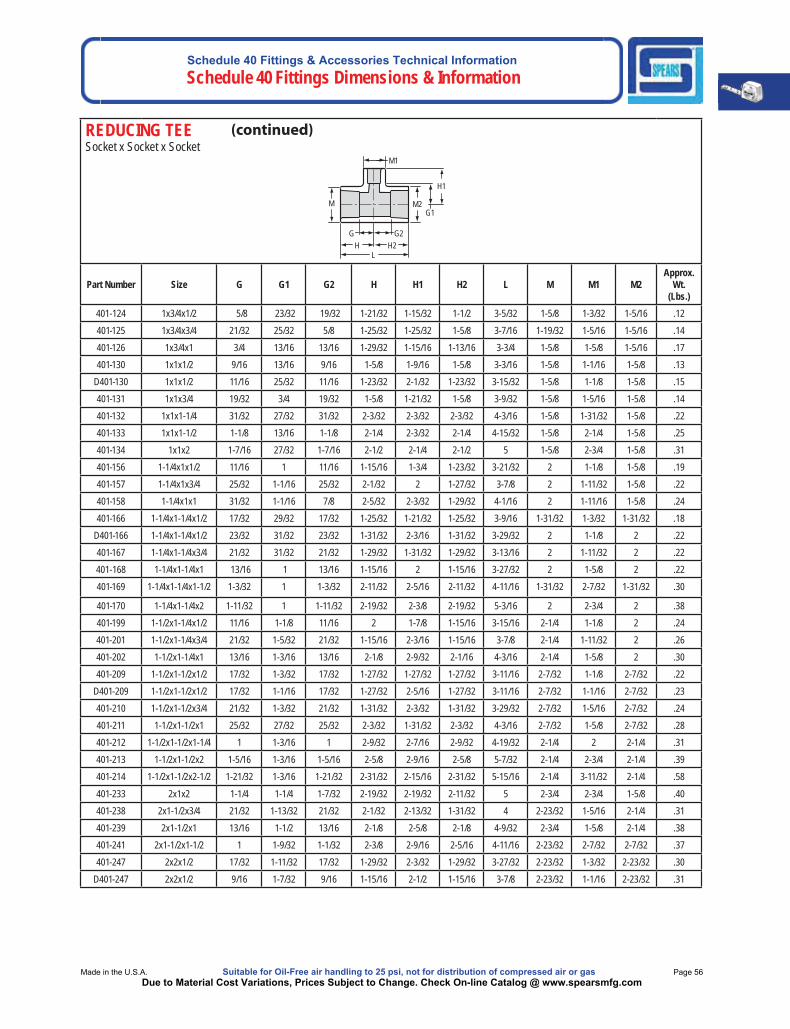
REDUCING TEE Socket x Socket x Socket
M
H1
H H2 G G2
L
G1 M2
M1
Part Number Size G G1 G2 H H1 H2 L M M1 M2Approx.
Wt. (Lbs.)
401-124 1x3/4x1/2 5/8 23/32 19/32 1-21/32 1-15/32 1-1/2 3-5/32 1-5/8 1-3/32 1-5/16 .12401-125 1x3/4x3/4 21/32 25/32 5/8 1-25/32 1-25/32 1-5/8 3-7/16 1-19/32 1-5/16 1-5/16 .14401-126 1x3/4x1 3/4 13/16 13/16 1-29/32 1-15/16 1-13/16 3-3/4 1-5/8 1-5/8 1-5/16 .17401-130 1x1x1/2 9/16 13/16 9/16 1-5/8 1-9/16 1-5/8 3-3/16 1-5/8 1-1/16 1-5/8 .13
D401-130 1x1x1/2 11/16 25/32 11/16 1-23/32 2-1/32 1-23/32 3-15/32 1-5/8 1-1/8 1-5/8 .15401-131 1x1x3/4 19/32 3/4 19/32 1-5/8 1-21/32 1-5/8 3-9/32 1-5/8 1-5/16 1-5/8 .14401-132 1x1x1-1/4 31/32 27/32 31/32 2-3/32 2-3/32 2-3/32 4-3/16 1-5/8 1-31/32 1-5/8 .22401-133 1x1x1-1/2 1-1/8 13/16 1-1/8 2-1/4 2-3/32 2-1/4 4-15/32 1-5/8 2-1/4 1-5/8 .25401-134 1x1x2 1-7/16 27/32 1-7/16 2-1/2 2-1/4 2-1/2 5 1-5/8 2-3/4 1-5/8 .31401-156 1-1/4x1x1/2 11/16 1 11/16 1-15/16 1-3/4 1-23/32 3-21/32 2 1-1/8 1-5/8 .19401-157 1-1/4x1x3/4 25/32 1-1/16 25/32 2-1/32 2 1-27/32 3-7/8 2 1-11/32 1-5/8 .22401-158 1-1/4x1x1 31/32 1-1/16 7/8 2-5/32 2-3/32 1-29/32 4-1/16 2 1-11/16 1-5/8 .24401-166 1-1/4x1-1/4x1/2 17/32 29/32 17/32 1-25/32 1-21/32 1-25/32 3-9/16 1-31/32 1-3/32 1-31/32 .18
D401-166 1-1/4x1-1/4x1/2 23/32 31/32 23/32 1-31/32 2-3/16 1-31/32 3-29/32 2 1-1/8 2 .22401-167 1-1/4x1-1/4x3/4 21/32 31/32 21/32 1-29/32 1-31/32 1-29/32 3-13/16 2 1-11/32 2 .22401-168 1-1/4x1-1/4x1 13/16 1 13/16 1-15/16 2 1-15/16 3-27/32 2 1-5/8 2 .22401-169 1-1/4x1-1/4x1-1/2 1-3/32 1 1-3/32 2-11/32 2-5/16 2-11/32 4-11/16 1-31/32 2-7/32 1-31/32 .30
401-170 1-1/4x1-1/4x2 1-11/32 1 1-11/32 2-19/32 2-3/8 2-19/32 5-3/16 2 2-3/4 2 .38401-199 1-1/2x1-1/4x1/2 11/16 1-1/8 11/16 2 1-7/8 1-15/16 3-15/16 2-1/4 1-1/8 2 .24401-201 1-1/2x1-1/4x3/4 21/32 1-5/32 21/32 1-15/16 2-3/16 1-15/16 3-7/8 2-1/4 1-11/32 2 .26401-202 1-1/2x1-1/4x1 13/16 1-3/16 13/16 2-1/8 2-9/32 2-1/16 4-3/16 2-1/4 1-5/8 2 .30401-209 1-1/2x1-1/2x1/2 17/32 1-3/32 17/32 1-27/32 1-27/32 1-27/32 3-11/16 2-7/32 1-1/8 2-7/32 .22
D401-209 1-1/2x1-1/2x1/2 17/32 1-1/16 17/32 1-27/32 2-5/16 1-27/32 3-11/16 2-7/32 1-1/16 2-7/32 .23401-210 1-1/2x1-1/2x3/4 21/32 1-3/32 21/32 1-31/32 2-3/32 1-31/32 3-29/32 2-7/32 1-5/16 2-7/32 .24401-211 1-1/2x1-1/2x1 25/32 27/32 25/32 2-3/32 1-31/32 2-3/32 4-3/16 2-7/32 1-5/8 2-7/32 .28401-212 1-1/2x1-1/2x1-1/4 1 1-3/16 1 2-9/32 2-7/16 2-9/32 4-19/32 2-1/4 2 2-1/4 .31401-213 1-1/2x1-1/2x2 1-5/16 1-3/16 1-5/16 2-5/8 2-9/16 2-5/8 5-7/32 2-1/4 2-3/4 2-1/4 .39401-214 1-1/2x1-1/2x2-1/2 1-21/32 1-3/16 1-21/32 2-31/32 2-15/16 2-31/32 5-15/16 2-1/4 3-11/32 2-1/4 .58
401-233 2x1x2 1-1/4 1-1/4 1-7/32 2-19/32 2-19/32 2-11/32 5 2-3/4 2-3/4 1-5/8 .40401-238 2x1-1/2x3/4 21/32 1-13/32 21/32 2-1/32 2-13/32 1-31/32 4 2-23/32 1-5/16 2-1/4 .31401-239 2x1-1/2x1 13/16 1-1/2 13/16 2-1/8 2-5/8 2-1/8 4-9/32 2-3/4 1-5/8 2-1/4 .38401-241 2x1-1/2x1-1/2 1 1-9/32 1-1/32 2-3/8 2-9/16 2-5/16 4-11/16 2-23/32 2-7/32 2-7/32 .37401-247 2x2x1/2 17/32 1-11/32 17/32 1-29/32 2-3/32 1-29/32 3-27/32 2-23/32 1-3/32 2-23/32 .30
D401-247 2x2x1/2 9/16 1-7/32 9/16 1-15/16 2-1/2 1-15/16 3-7/8 2-23/32 1-1/16 2-23/32 .31
Schedule 40 Fittings & Accessories Technical Information Schedule 40 Fittings Dimensions & Information
Page 57 Suitable for Oil-Free air handling to 25 psi, not for distribution of compressed air or gas Spears® Manufacturing CompanyDue to Material Cost Variations, Prices Subject to Change. Check On-line Catalog @ www.spearsmfg.com
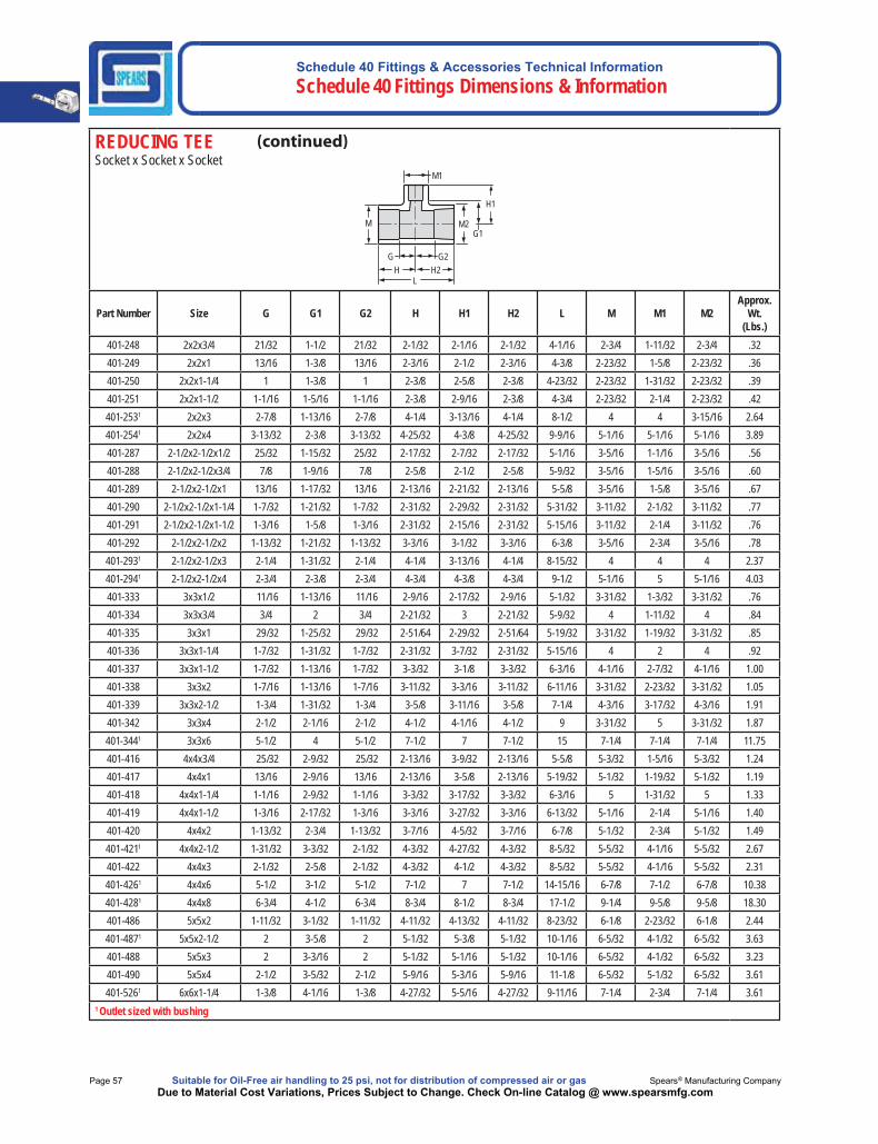
REDUCING TEE Socket x Socket x Socket
M
H1
H H2 G G2
L
G1 M2
M1
Part Number Size G G1 G2 H H1 H2 L M M1 M2Approx.
Wt. (Lbs.)
401-248 2x2x3/4 21/32 1-1/2 21/32 2-1/32 2-1/16 2-1/32 4-1/16 2-3/4 1-11/32 2-3/4 .32401-249 2x2x1 13/16 1-3/8 13/16 2-3/16 2-1/2 2-3/16 4-3/8 2-23/32 1-5/8 2-23/32 .36401-250 2x2x1-1/4 1 1-3/8 1 2-3/8 2-5/8 2-3/8 4-23/32 2-23/32 1-31/32 2-23/32 .39401-251 2x2x1-1/2 1-1/16 1-5/16 1-1/16 2-3/8 2-9/16 2-3/8 4-3/4 2-23/32 2-1/4 2-23/32 .42401-2531 2x2x3 2-7/8 1-13/16 2-7/8 4-1/4 3-13/16 4-1/4 8-1/2 4 4 3-15/16 2.64401-2541 2x2x4 3-13/32 2-3/8 3-13/32 4-25/32 4-3/8 4-25/32 9-9/16 5-1/16 5-1/16 5-1/16 3.89401-287 2-1/2x2-1/2x1/2 25/32 1-15/32 25/32 2-17/32 2-7/32 2-17/32 5-1/16 3-5/16 1-1/16 3-5/16 .56401-288 2-1/2x2-1/2x3/4 7/8 1-9/16 7/8 2-5/8 2-1/2 2-5/8 5-9/32 3-5/16 1-5/16 3-5/16 .60401-289 2-1/2x2-1/2x1 13/16 1-17/32 13/16 2-13/16 2-21/32 2-13/16 5-5/8 3-5/16 1-5/8 3-5/16 .67401-290 2-1/2x2-1/2x1-1/4 1-7/32 1-21/32 1-7/32 2-31/32 2-29/32 2-31/32 5-31/32 3-11/32 2-1/32 3-11/32 .77401-291 2-1/2x2-1/2x1-1/2 1-3/16 1-5/8 1-3/16 2-31/32 2-15/16 2-31/32 5-15/16 3-11/32 2-1/4 3-11/32 .76401-292 2-1/2x2-1/2x2 1-13/32 1-21/32 1-13/32 3-3/16 3-1/32 3-3/16 6-3/8 3-5/16 2-3/4 3-5/16 .78401-2931 2-1/2x2-1/2x3 2-1/4 1-31/32 2-1/4 4-1/4 3-13/16 4-1/4 8-15/32 4 4 4 2.37401-2941 2-1/2x2-1/2x4 2-3/4 2-3/8 2-3/4 4-3/4 4-3/8 4-3/4 9-1/2 5-1/16 5 5-1/16 4.03401-333 3x3x1/2 11/16 1-13/16 11/16 2-9/16 2-17/32 2-9/16 5-1/32 3-31/32 1-3/32 3-31/32 .76401-334 3x3x3/4 3/4 2 3/4 2-21/32 3 2-21/32 5-9/32 4 1-11/32 4 .84401-335 3x3x1 29/32 1-25/32 29/32 2-51/64 2-29/32 2-51/64 5-19/32 3-31/32 1-19/32 3-31/32 .85401-336 3x3x1-1/4 1-7/32 1-31/32 1-7/32 2-31/32 3-7/32 2-31/32 5-15/16 4 2 4 .92401-337 3x3x1-1/2 1-7/32 1-13/16 1-7/32 3-3/32 3-1/8 3-3/32 6-3/16 4-1/16 2-7/32 4-1/16 1.00401-338 3x3x2 1-7/16 1-13/16 1-7/16 3-11/32 3-3/16 3-11/32 6-11/16 3-31/32 2-23/32 3-31/32 1.05401-339 3x3x2-1/2 1-3/4 1-31/32 1-3/4 3-5/8 3-11/16 3-5/8 7-1/4 4-3/16 3-17/32 4-3/16 1.91401-342 3x3x4 2-1/2 2-1/16 2-1/2 4-1/2 4-1/16 4-1/2 9 3-31/32 5 3-31/32 1.87401-3441 3x3x6 5-1/2 4 5-1/2 7-1/2 7 7-1/2 15 7-1/4 7-1/4 7-1/4 11.75401-416 4x4x3/4 25/32 2-9/32 25/32 2-13/16 3-9/32 2-13/16 5-5/8 5-3/32 1-5/16 5-3/32 1.24401-417 4x4x1 13/16 2-9/16 13/16 2-13/16 3-5/8 2-13/16 5-19/32 5-1/32 1-19/32 5-1/32 1.19401-418 4x4x1-1/4 1-1/16 2-9/32 1-1/16 3-3/32 3-17/32 3-3/32 6-3/16 5 1-31/32 5 1.33401-419 4x4x1-1/2 1-3/16 2-17/32 1-3/16 3-3/16 3-27/32 3-3/16 6-13/32 5-1/16 2-1/4 5-1/16 1.40401-420 4x4x2 1-13/32 2-3/4 1-13/32 3-7/16 4-5/32 3-7/16 6-7/8 5-1/32 2-3/4 5-1/32 1.49401-4211 4x4x2-1/2 1-31/32 3-3/32 2-1/32 4-3/32 4-27/32 4-3/32 8-5/32 5-5/32 4-1/16 5-5/32 2.67401-422 4x4x3 2-1/32 2-5/8 2-1/32 4-3/32 4-1/2 4-3/32 8-5/32 5-5/32 4-1/16 5-5/32 2.31401-4261 4x4x6 5-1/2 3-1/2 5-1/2 7-1/2 7 7-1/2 14-15/16 6-7/8 7-1/2 6-7/8 10.38401-4281 4x4x8 6-3/4 4-1/2 6-3/4 8-3/4 8-1/2 8-3/4 17-1/2 9-1/4 9-5/8 9-5/8 18.30401-486 5x5x2 1-11/32 3-1/32 1-11/32 4-11/32 4-13/32 4-11/32 8-23/32 6-1/8 2-23/32 6-1/8 2.44401-4871 5x5x2-1/2 2 3-5/8 2 5-1/32 5-3/8 5-1/32 10-1/16 6-5/32 4-1/32 6-5/32 3.63401-488 5x5x3 2 3-3/16 2 5-1/32 5-1/16 5-1/32 10-1/16 6-5/32 4-1/32 6-5/32 3.23401-490 5x5x4 2-1/2 3-5/32 2-1/2 5-9/16 5-3/16 5-9/16 11-1/8 6-5/32 5-1/32 6-5/32 3.61401-5261 6x6x1-1/4 1-3/8 4-1/16 1-3/8 4-27/32 5-5/16 4-27/32 9-11/16 7-1/4 2-3/4 7-1/4 3.61
1 Outlet sized with bushing

Schedule 40 Fittings & Accessories Technical InformationSchedule 40 Fittings Dimensions & Information
Made in the U.S.A. Suitable for Oil-Free air handling to 25 psi, not for distribution of compressed air or gas Page 58Due to Material Cost Variations, Prices Subject to Change. Check On-line Catalog @ www.spearsmfg.com
$
$
$
$
$
$$
$
$
$
$
$
REDUCING TEE Socket x Socket x Socket
M
H1
H H2 G G2
L
G1 M2
M1
Part Number Size G G1 G2 H H1 H2 L M M1 M2Approx.
Wt. (Lbs.)
401-5271 6x6x1-1/2 1-3/8 3-7/8 1-3/8 4-27/32 5-3/16 4-27/32 9-11/16 7-1/4 2-11/16 7-1/4 3.60401-528 6x6x2 1-13/32 3-5/8 1-13/32 4-13/32 4-31/32 4-13/32 8-27/32 7-1/4 2-3/4 7-1/4 3.28401-5291 6x6x2-1/2 1-31/32 4-1/8 1-31/32 4-31/32 5-7/8 4-31/32 9-15/16 7-1/4 4-1/32 7-1/4 4.28401-530 6x6x3 1-31/32 3-5/8 1-31/32 4-31/32 5-1/2 4-31/32 10 7-1/4 4 7-1/4 3.90401-532 6x6x4 2-17/32 3-5/8 2-17/32 5-9/16 5-5/8 5-9/16 11-1/8 7-1/4 5 7-1/4 4.38401-5331 6x6x5 3-1/2 4-1/2 3-1/2 7 7-1/2 7 14 7-3/16 7-3/16 7-3/8 8.46401-5351 6x6x8 5-3/8 5-1/2 5-3/8 8-7/8 9-1/2 8-7/8 17-3/4 9-1/2 9-3/4 9-1/2 19.21401-5371 6x6x10 8 5-13/16 8 11-3/8 10-13/16 11-3/8 22-3/4 11-1/2 11-9/16 11-1/2 38.30401-5781 8x8x2 2 5-7/8 2 6 7 6 12 9-1/4 4 9-1/4 11.71401-5791 8x8x2-1/2 2 5-5/16 2 6 7-5/16 6 12 9-5/16 4 9-5/16 6.62401-580 8x8x3 1-31/32 4-3/4 1-31/32 6-1/32 6-3/4 6-1/32 12-1/16 9-11/32 4 9-11/32 6.44401-582 8x8x4 2-17/32 4-11/16 2-17/32 6-17/32 6-11/16 6-17/32 13-1/16 9-9/32 4-31/32 9-9/32 7.02401-5831 8x8x5 3-21/32 5-1/4 3-21/32 7-21/32 8-1/4 7-21/32 15-5/16 9-5/16 7-1/4 9-5/16 10.60401-585 8x8x6 3-5/8 4-3/4 3-5/8 7-21/32 7-25/32 7-21/32 15-11/32 9-11/32 7-1/4 9-11/32 8.90401-5891 8x8x10 6-23/32 5-11/16 6-23/32 11-7/32 10-1/2 11-7/32 22-7/16 11-9/16 11-9/16 11-9/16 34.76401-621F 10x10x2 4-7/8 7-1/4 4-7/8 10-1/8 9 10-1/8 20-1/4 11-1/2 2-11/16 11-1/2 19.60401-622F 10x10x2-1/2 5-5/8 7-3/4 5-5/8 10-7/8 9-3/4 10-7/8 21-3/4 11-1/2 3-1/4 11-1/2 20.26401-6231 10x10x3 3-13/16 7 3-13/16 9-3/8 9 9-3/8 18-3/4 12 7-1/2 12 25.54401-6241 10x10x4 3-27/32 7-3/8 3-27/32 9-11/32 9-3/8 9-11/32 18-11/16 12 7-1/2 12 25.63401-626F 10x10x6 6-7/8 8-3/8 6-7/8 12-1/8 11-5/8 12-1/8 24-1/4 11-1/2 7-3/16 11-1/2 26.48401-6281 10x10x8 5-3/4 7-3/16 5-3/4 10-7/8 11-1/4 10-7/8 21-11/16 11-11/16 11-11/16 11-1/2 29.85401-661F 12x12x2 5-1/4 8-1/4 5-1/4 11-1/2 10 11-1/2 23 13-9/16 2-11/16 13-1/2 25.00401-662F 12x12x2-1/2 5-3/4 8-3/4 5-3/4 12 10-3/4 12 24 13-9/16 3-1/4 13-9/16 28.61401-663F 12x12x3 5-3/4 9 5-3/4 12 11-1/4 12 24 13-9/16 3-15/16 13-9/16 31.41401-664F 12x12x4 7 9-5/16 7 13-1/4 11-9/16 13-1/4 26-1/2 13-9/16 5 13-9/16 32.40401-6661 12x12x6 4-7/8 8-5/16 4-7/8 11-7/16 11-3/4 11-7/16 22-13/16 14-1/4 9-3/4 14-1/4 44.02401-668 12x12x8 4-27/32 7-1/8 4-27/32 11-13/32 11-1/8 11-13/32 22-13/16 14-1/4 9-3/4 14-1/4 40.00401-670 12x12x10 6-13/16 7-3/8 6-13/16 12-13/16 13-1/4 12-13/16 25-5/8 13-3/4 13-3/4 13-3/4 50.00
401-670F 12x12x10 10-1/4 10-3/8 10-1/4 16-1/2 15-5/8 16-1/2 33 13-9/16 11-1/2 13-9/16 50.00401-676F 12x12x16 18-1/2 12-3/4 18-1/2 30-1/4 20-3/4 30-1/4 60-1/2 14-1/8 17 14-1/8 144.87401-678F 12x12x18 14-1/4 13 17-7/8 23-1/4 22 23-7/8 47-3/4 19-1/8 19-1/8 19-1/8 252.00401-691F 14x14x2 5-7/8 8-13/16 5-7/8 12-7/8 10-9/16 12-7/8 25-3/4 14-7/8 2-11/16 14-7/8 35.53401-693F 14x14x3 6-1/2 9-9/16 6-1/2 13-1/2 11-13/16 13-1/2 27 14-7/8 3-15/16 14-7/8 38.35401-694F 14x14x4 7-3/8 9-7/8 7-3/8 14-3/8 12-1/8 14-3/8 28-3/4 14-7/8 5 14-7/8 38.58401-696F 14x14x6 7-7/8 9-15/16 7-7/8 14-7/8 13-3/16 14-7/8 29-3/4 14-7/8 7-3/16 14-7/8 45.70401-698F 14x14x8 8-7/8 9-7/8 8-7/8 15-7/8 14-1/8 15-7/8 31-3/4 14-7/8 9-1/4 14-7/8 51.99
1 Outlet sized with bushing
Schedule 40 Fittings & Accessories Technical Information Schedule 40 Fittings Dimensions & Information
Page 59 Suitable for Oil-Free air handling to 25 psi, not for distribution of compressed air or gas Spears® Manufacturing CompanyDue to Material Cost Variations, Prices Subject to Change. Check On-line Catalog @ www.spearsmfg.com
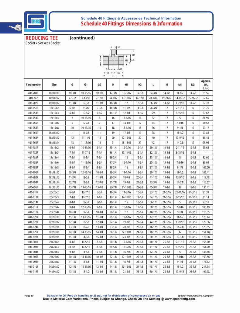
REDUCING TEE Socket x Socket x Socket
M
H1
H H2 G G2
L
G1 M2
M1
Part Number Size G G1 G2 H H1 H2 L M M1 M2Approx.
Wt. (Lbs.)
401-700F 14x14x10 10-3/8 10-15/16 10-3/8 17-3/8 16-3/16 17-3/8 34-3/4 14-7/8 11-1/2 14-7/8 61.56401-702 14x14x12 7-1/32 7-13/32 7-1/32 14-1/32 13-13/32 14-1/32 28-1/16 15-21/32 14-11/32 15-21/32 62.65
401-702F 14x14x12 11-3/8 10-3/4 11-3/8 18-3/8 17 18-3/8 36-3/4 14-7/8 13-9/16 14-7/8 62.78401-751F 16x16x2 6-3/8 9-3/4 6-3/8 14-3/8 11-1/2 14-3/8 28-3/4 17 2-11/16 17 51.76401-753F 16x16x3 6-1/2 10-1/2 6-1/2 14-1/2 12-3/4 14-1/2 29 17 3-15/16 17 57.67401-754F 16x16x4 8 10-13/16 8 16 13-1/16 16 32 17 5 17 58.90401-756F 16x16x6 9 10-7/8 9 17 14-1/8 17 34 17 7-3/16 17 66.52401-758F 16x16x8 10 10-13/16 10 18 15-1/16 18 36 17 9-1/4 17 73.17401-760F 16x16x10 11 11-7/8 11 19 17-1/8 19 38 17 11-1/2 17 73.88401-762F 16x16x12 12 11-11/6 12 20 17-15/16 20 40 17 13-9/16 17 85.48401-764F 16x16x14 13 11-15/16 13 21 18-15/16 21 42 17 14-7/8 17 95.95401-781F 18x18x2 6-1/4 10-11/16 6-1/4 15-1/4 12-7/16 15-1/4 30-1/2 19-1/8 2-11/16 19-1/8 65.63401-783F 18x18x3 7-1/4 11-7/16 7-1/4 16-1/4 13-11/16 16-1/4 32-1/2 19-1/8 3-15/16 19-1/8 ---401-784F 18x18x4 7-3/4 11-3/4 7-3/4 16-3/4 14 16-3/4 33-1/2 19-1/8 5 19-1/8 82.00401-786F 18x18x6 8-3/4 11-13/16 8-3/4 17-3/4 15-1/16 17-3/4 35-1/2 19-1/8 7-3/16 19-1/8 88.04401-788F 18x18x8 9-3/4 11-3/4 9-3/4 18-3/4 16 18-3/4 37-1/2 19-1/8 9-1/4 19-1/8 107.00401-790F 18x18x10 10-3/4 12-13/16 10-3/4 19-3/4 18-1/16 19-3/4 39-1/2 19-1/8 11-1/2 19-1/8 105.41401-792F 18x18x12 11-3/4 12-5/8 11-3/4 20-3/4 18-7/8 20-3/4 41-1/2 19-1/8 13-9/16 19-1/8 113.48401-794F 18x18x14 12-7/8 12-7/8 12-7/8 21-7/8 19-7/8 21-7/8 43-3/4 19-1/8 14-7/8 19-1/8 116.67401-796F 18x18x16 13-7/8 13-13/16 13-7/8 22-7/8 21-13/16 22-7/8 45-3/4 19-1/8 17 19-1/8 134.41401-811F 20x20x2 6-3/4 12-7/16 6-3/4 16-3/4 14-3/16 16-3/4 33-1/2 21-3/16 21-11/16 21-3/16 81.39401-813F 20x20x3 7-1/4 12-7/16 7-1/4 17-1/4 14-11/16 17-1/4 34-1/2 21-3/16 3-15/16 21-3/16 91.14401-814F 20x20x4 8-1/4 12-3/4 8-1/4 18-1/4 15 18-1/4 36-1/2 21-3/16 5 21-3/16 72.10401-816F 20x20x6 9-1/4 12-13/16 9-1/4 19-1/4 16-1/16 19-1/4 38-1/2 21-3/16 7-3/16 21-3/16 106.19401-818F 20x20x8 10-1/4 12-3/4 10-1/4 20-1/4 17 20-1/4 40-1/2 21-3/16 9-1/4 21-3/16 115.35401-820F 20x20x10 11-1/4 13-13/16 11-1/4 21-1/4 19-1/16 21-1/4 42-1/2 21-3/16 11-1/2 21-3/16 125.44401-822F 20x20x12 12-1/4 13-5/8 12-1/4 22-1/4 19-7/8 22-1/4 44-1/2 21-3/16 13-9/16 21-3/16 129.36401-824F 20x20x14 13-1/4 13-7/8 13-1/4 23-1/4 20-7/8 23-1/4 46-1/2 21-3/16 14-7/8 21-3/16 123.55401-826F 20x20x16 14-1/4 14-13/16 14-1/4 24-1/4 22-13/16 24-1/4 48-1/2 21-3/16 17 21-3/16 154.48401-828F 20x20x18 15-1/4 14-3/8 15-1/4 25-1/4 23-3/8 25-1/4 50-1/2 21-3/16 19-1/8 21-3/16 176.98401-901F 24x24x2 8-1/8 14-5/16 8-1/8 20-1/8 16-1/16 20-1/8 40-1/4 25-3/8 2-11/16 25-3/8 156.00401-903F 24x24x3 8-5/8 14-5/16 8-5/8 20-5/8 16-9/16 20-5/8 41-1/4 25-3/8 3-15/16 25-3/8 161.00401-904F 24x24x4 9-1/8 14-5/8 9-1/8 21-1/8 16-7/8 21-1/8 42-1/4 25-3/8 5 25-3/8 148.46401-906F 24x24x6 10-1/8 14-11/16 10-1/8 22-1/8 17-15/16 22-1/8 44-1/4 25-3/8 7-3/16 25-3/8 159.56401-908F 24x24x8 11-1/8 14-5/8 11-1/8 23-1/8 18-7/8 23-1/8 46-1/4 25-3/8 9-1/4 25-3/8 171.52401-910F 24x24x10 12-1/8 15-11/16 12-1/8 24-1/8 20-15/16 24-1/8 48-1/4 25-3/8 11-1/2 25-3/8 213.94401-912F 24x24x12 13-1/8 15-1/2 13-1/8 25-1/8 21-3/4 25-1/8 50-1/4 25-3/8 13-9/16 25-3/8 199.98
Schedule 40 Fittings & Accessories Technical InformationSchedule 40 Fittings Dimensions & Information
Made in the U.S.A. Suitable for Oil-Free air handling to 25 psi, not for distribution of compressed air or gas Page 60Due to Material Cost Variations, Prices Subject to Change. Check On-line Catalog @ www.spearsmfg.com
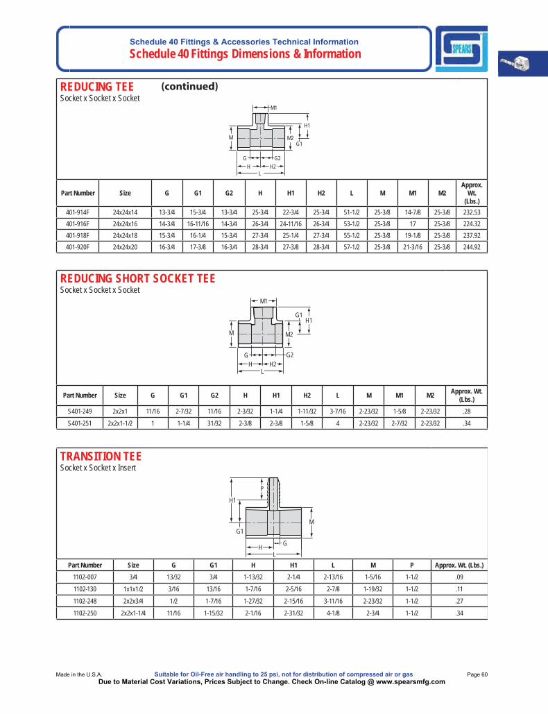
REDUCING TEE Socket x Socket x Socket
M
H1
H H2 G G2
L
G1 M2
M1
Part Number Size G G1 G2 H H1 H2 L M M1 M2Approx.
Wt. (Lbs.)
401-914F 24x24x14 13-3/4 15-3/4 13-3/4 25-3/4 22-3/4 25-3/4 51-1/2 25-3/8 14-7/8 25-3/8 232.53401-916F 24x24x16 14-3/4 16-11/16 14-3/4 26-3/4 24-11/16 26-3/4 53-1/2 25-3/8 17 25-3/8 224.32401-918F 24x24x18 15-3/4 16-1/4 15-3/4 27-3/4 25-1/4 27-3/4 55-1/2 25-3/8 19-1/8 25-3/8 237.92401-920F 24x24x20 16-3/4 17-3/8 16-3/4 28-3/4 27-3/8 28-3/4 57-1/2 25-3/8 21-3/16 25-3/8 244.92
REDUCING SHORT SOCKET TEESocket x Socket x Socket
M
H1
HG G2
L
G1
M2
M1
H2
Part Number Size G G1 G2 H H1 H2 L M M1 M2 Approx. Wt. (Lbs.)
S401-249 2x2x1 11/16 2-7/32 11/16 2-3/32 1-1/4 1-11/32 3-7/16 2-23/32 1-5/8 2-23/32 .28
S401-251 2x2x1-1/2 1 1-1/4 31/32 2-3/8 2-3/8 1-5/8 4 2-23/32 2-7/32 2-23/32 .34
TRANSITION TEESocket x Socket x Insert
L
H1
M
GH
P
G1
Part Number Size G G1 H H1 L M P Approx. Wt. (Lbs.)1102-007 3/4 13/32 3/4 1-13/32 2-1/4 2-13/16 1-5/16 1-1/2 .09
1102-130 1x1x1/2 3/16 13/16 1-7/16 2-5/16 2-7/8 1-19/32 1-1/2 .11
1102-248 2x2x3/4 1/2 1-7/16 1-27/32 2-15/16 3-11/16 2-23/32 1-1/2 .27
1102-250 2x2x1-1/4 11/16 1-15/32 2-1/16 2-31/32 4-1/8 2-3/4 1-1/2 .34
Schedule 40 Fittings & Accessories Technical Information Schedule 40 Fittings Dimensions & Information
Page 61 Suitable for Oil-Free air handling to 25 psi, not for distribution of compressed air or gas Spears® Manufacturing CompanyDue to Material Cost Variations, Prices Subject to Change. Check On-line Catalog @ www.spearsmfg.com
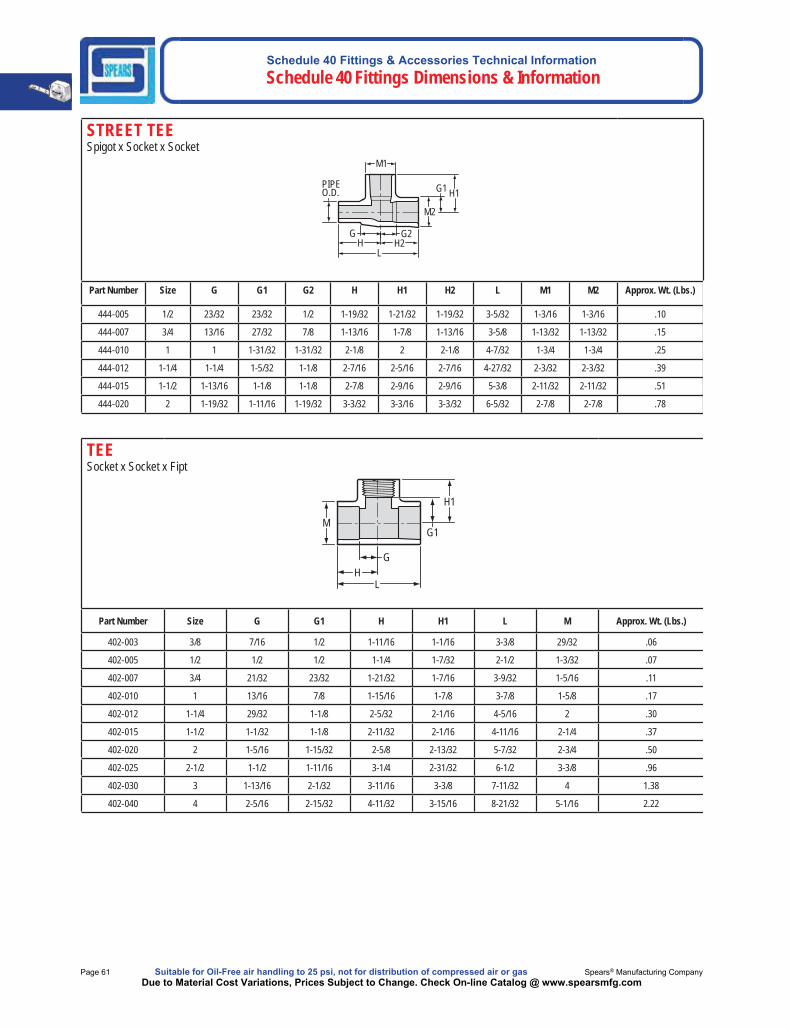
STREET TEESpigot x Socket x Socket
LH2H
PIPEO.D.
M1
M2
H1G1
G2G
Part Number Size G G1 G2 H H1 H2 L M1 M2 Approx. Wt. (Lbs.)
444-005 1/2 23/32 23/32 1/2 1-19/32 1-21/32 1-19/32 3-5/32 1-3/16 1-3/16 .10
444-007 3/4 13/16 27/32 7/8 1-13/16 1-7/8 1-13/16 3-5/8 1-13/32 1-13/32 .15
444-010 1 1 1-31/32 1-31/32 2-1/8 2 2-1/8 4-7/32 1-3/4 1-3/4 .25
444-012 1-1/4 1-1/4 1-5/32 1-1/8 2-7/16 2-5/16 2-7/16 4-27/32 2-3/32 2-3/32 .39
444-015 1-1/2 1-13/16 1-1/8 1-1/8 2-7/8 2-9/16 2-9/16 5-3/8 2-11/32 2-11/32 .51
444-020 2 1-19/32 1-11/16 1-19/32 3-3/32 3-3/16 3-3/32 6-5/32 2-7/8 2-7/8 .78
TEESocket x Socket x Fipt
M
H1
HG
L
G1
Part Number Size G G1 H H1 L M Approx. Wt. (Lbs.)
402-003 3/8 7/16 1/2 1-11/16 1-1/16 3-3/8 29/32 .06
402-005 1/2 1/2 1/2 1-1/4 1-7/32 2-1/2 1-3/32 .07
402-007 3/4 21/32 23/32 1-21/32 1-7/16 3-9/32 1-5/16 .11
402-010 1 13/16 7/8 1-15/16 1-7/8 3-7/8 1-5/8 .17
402-012 1-1/4 29/32 1-1/8 2-5/32 2-1/16 4-5/16 2 .30
402-015 1-1/2 1-1/32 1-1/8 2-11/32 2-1/16 4-11/16 2-1/4 .37
402-020 2 1-5/16 1-15/32 2-5/8 2-13/32 5-7/32 2-3/4 .50
402-025 2-1/2 1-1/2 1-11/16 3-1/4 2-31/32 6-1/2 3-3/8 .96
402-030 3 1-13/16 2-1/32 3-11/16 3-3/8 7-11/32 4 1.38
402-040 4 2-5/16 2-15/32 4-11/32 3-15/16 8-21/32 5-1/16 2.22
Schedule 40 Fittings & Accessories Technical InformationSchedule 40 Fittings Dimensions & Information
Made in the U.S.A. Suitable for Oil-Free air handling to 25 psi, not for distribution of compressed air or gas Page 62Due to Material Cost Variations, Prices Subject to Change. Check On-line Catalog @ www.spearsmfg.com
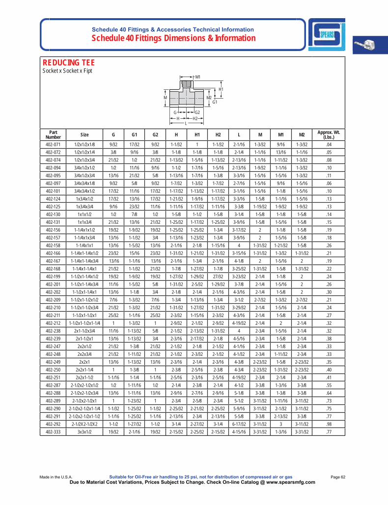
REDUCING TEE Socket x Socket x Fipt
L
M
H1
H H2
G1M2
G
M1
G2
Part Number Size G G1 G2 H H1 H2 L M M1 M2 Approx. Wt.
(Lbs.)402-071 1/2x1/2x1/8 9/32 17/32 9/32 1-1/32 1 1-1/32 2-1/16 1-3/32 9/16 1-3/32 .04402-072 1/2x1/2x1/4 3/8 9/16 3/8 1-1/8 1-1/8 1-1/8 2-1/4 1-1/16 13/16 1-1/16 .05402-074 1/2x1/2x3/4 21/32 1/2 21/32 1-13/32 1-5/16 1-13/32 2-13/16 1-1/16 1-11/32 1-3/32 .08402-094 3/4x1/2x1/2 1/2 11/16 9/16 1-1/2 1-7/16 1-5/16 2-13/16 1-9/32 1-1/16 1-3/32 .10402-095 3/4x1/2x3/4 13/16 21/32 5/8 1-13/16 1-7/16 1-3/8 3-3/16 1-5/16 1-5/16 1-3/32 .11402-097 3/4x3/4x1/8 9/32 5/8 9/32 1-7/32 1-3/32 1-7/32 2-7/16 1-5/16 9/16 1-5/16 .06402-101 3/4x3/4x1/2 17/32 11/16 17/32 1-17/32 1-13/32 1-17/32 3-1/16 1-5/16 1-1/8 1-5/16 .10402-124 1x3/4x1/2 17/32 13/16 17/32 1-21/32 1-9/16 1-17/32 3-3/16 1-5/8 1-1/16 1-5/16 .13402-125 1x3/4x3/4 9/16 23/32 11/16 1-11/16 1-17/32 1-11/16 3-3/8 1-19/32 1-9/32 1-9/32 .13402-130 1x1x1/2 1/2 7/8 1/2 1-5/8 1-1/2 1-5/8 3-1/4 1-5/8 1-1/8 1-5/8 .14402-131 1x1x3/4 21/32 13/16 21/32 1-25/32 1-17/32 1-25/32 3-9/16 1-5/8 1-5/16 1-5/8 .15402-156 1-1/4x1x1/2 19/32 1-9/32 19/32 1-25/32 1-25/32 1-3/4 3-17/32 2 1-1/8 1-5/8 .19402-157 1-1/4x1x3/4 13/16 1-1/32 3/4 1-13/16 1-23/32 1-3/4 3-9/16 2 1-5/16 1-5/8 .18402-158 1-1/4x1x1 13/16 1-5/32 13/16 2-1/16 2-1/8 1-15/16 4 1-31/32 1-21/32 1-5/8 .26402-166 1-1/4x1-1/4x1/2 23/32 15/16 23/32 1-31/32 1-21/32 1-31/32 3-15/16 1-31/32 1-3/32 1-31/32 .21402-167 1-1/4x1-1/4x3/4 13/16 1-1/16 13/16 2-1/16 1-3/4 2-1/16 4-1/8 2 1-5/16 2 .19402-168 1-1/4x1-1/4x1 21/32 1-1/32 21/32 1-7/8 1-27/32 1-7/8 3-25/32 1-31/32 1-5/8 1-31/32 .22402-199 1-1/2x1-1/4x1/2 19/32 1-9/32 19/32 1-27/32 1-29/32 27/32 3-23/32 2-1/4 1-1/8 2 .24402-201 1-1/2x1-1/4x3/4 11/16 1-5/32 5/8 1-31/32 2-5/32 1-29/32 3-7/8 2-1/4 1-5/16 2 .26402-202 1-1/2x1-1/4x1 13/16 1-1/8 3/4 2-1/8 2-1/4 2-1/16 4-3/16 2-1/4 1-5/8 2 .30402-209 1-1/2x1-1/2x1/2 7/16 1-3/32 7/16 1-3/4 1-13/16 1-3/4 3-1/2 2-7/32 1-3/32 2-7/32 .21402-210 1-1/2x1-1/2x3/4 21/32 1-3/32 21/32 1-31/32 1-27/32 1-31/32 3-29/32 2-1/4 1-5/16 2-1/4 .24402-211 1-1/2x1-1/2x1 25/32 1-1/16 25/32 2-3/32 1-15/16 2-3/32 4-3/16 2-1/4 1-5/8 2-1/4 .27402-212 1-1/2x1-1/2x1-1/4 1 1-3/32 1 2-9/32 2-1/32 2-9/32 4-19/32 2-1/4 2 2-1/4 .32402-238 2x1-1/2x3/4 11/16 1-13/32 5/8 2-1/32 2-13/32 1-31/32 4 2-3/4 1-5/16 2-1/4 .32402-239 2x1-1/2x1 13/16 1-13/32 3/4 2-3/16 2-17/32 2-1/8 4-5/16 2-3/4 1-5/8 2-1/4 .38402-247 2x2x1/2 21/32 1-3/8 21/32 2-1/32 2-1/8 2-1/32 4-1/16 2-3/4 1-1/8 2-3/4 .33402-248 2x2x3/4 21/32 1-11/32 21/32 2-1/32 2-3/32 2-1/32 4-1/32 2-3/4 1-11/32 2-3/4 .33402-249 2x2x1 13/16 1-13/32 13/16 2-3/16 2-1/4 2-3/16 4-3/8 2-23/32 1-5/8 2-23/32 .35402-250 2x2x1-1/4 1 1-3/8 1 2-3/8 2-5/16 2-3/8 4-3/4 2-23/32 1-31/32 2-23/32 .40402-251 2x2x1-1/2 1-1/16 1-1/4 1-1/16 2-5/16 2-3/16 2-5/16 4-19/32 2-3/4 2-1/4 2-3/4 .41402-287 2-1/2x2-1/2x1/2 1/2 1-11/16 1/2 2-1/4 2-3/8 2-1/4 4-1/2 3-3/8 1-3/16 3-3/8 .55402-288 2-1/2x2-1/2x3/4 13/16 1-11/16 13/16 2-9/16 2-7/16 2-9/16 5-1/8 3-3/8 1-3/8 3-3/8 .64402-289 2-1/2x2-1/2x1 1 1-23/32 1 2-3/4 2-5/8 2-3/4 5-1/2 3-11/32 1-11/16 3-11/32 .73402-290 2-1/2x2-1/2x1-1/4 1-1/32 1-25/32 1-1/32 2-25/32 2-21/32 2-25/32 5-9/16 3-11/32 2-1/32 3-11/32 .75402-291 2-1/2x2-1/2x1-1/2 1-1/16 1-25/32 1-1/16 2-13/16 2-3/4 2-13/16 5-5/8 3-3/8 2-13/32 3-3/8 .77402-292 2-1/2X2-1/2X2 1-1/2 1-27/32 1-1/2 3-1/4 2-27/32 3-1/4 6-17/32 3-11/32 3 3-11/32 .98402-333 3x3x1/2 19/32 2-1/16 19/32 2-15/32 2-25/32 2-15/32 4-15/16 3-31/32 1-3/16 3-31/32 .77
Schedule 40 Fittings & Accessories Technical Information Schedule 40 Fittings Dimensions & Information
Page 63 Suitable for Oil-Free air handling to 25 psi, not for distribution of compressed air or gas Spears® Manufacturing CompanyDue to Material Cost Variations, Prices Subject to Change. Check On-line Catalog @ www.spearsmfg.com
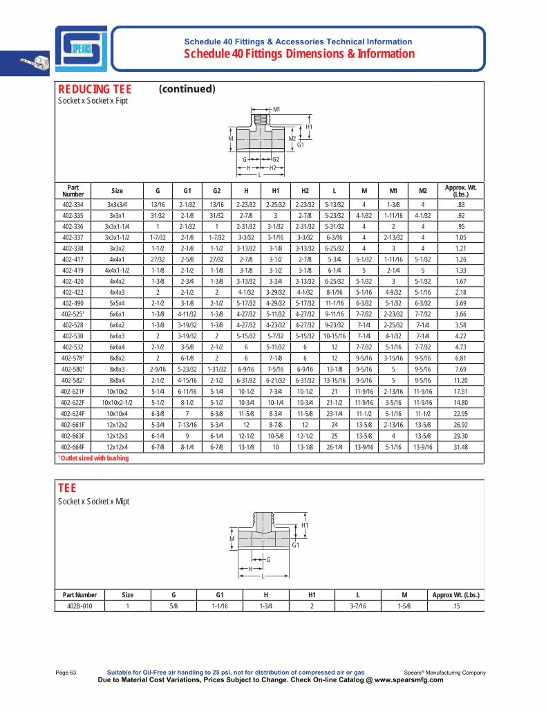
REDUCING TEE Socket x Socket x Fipt
L
M
H1
H H2
G1M2
G
M1
G2
Part Number Size G G1 G2 H H1 H2 L M M1 M2 Approx. Wt.
(Lbs.)402-334 3x3x3/4 13/16 2-1/32 13/16 2-23/32 2-25/32 2-23/32 5-13/32 4 1-3/8 4 .83402-335 3x3x1 31/32 2-1/8 31/32 2-7/8 3 2-7/8 5-23/32 4-1/32 1-11/16 4-1/32 .92402-336 3x3x1-1/4 1 2-1/32 1 2-31/32 3-1/32 2-31/32 5-31/32 4 2 4 .95402-337 3x3x1-1/2 1-7/32 2-1/8 1-7/32 3-3/32 3-1/16 3-3/32 6-3/16 4 2-13/32 4 1.05402-338 3x3x2 1-1/2 2-1/8 1-1/2 3-13/32 3-1/8 3-13/32 6-25/32 4 3 4 1.21402-417 4x4x1 27/32 2-5/8 27/32 2-7/8 3-1/2 2-7/8 5-3/4 5-1/32 1-11/16 5-1/32 1.26402-419 4x4x1-1/2 1-1/8 2-1/2 1-1/8 3-1/8 3-1/2 3-1/8 6-1/4 5 2-1/4 5 1.33402-420 4x4x2 1-3/8 2-3/4 1-3/8 3-13/32 3-3/4 3-13/32 6-25/32 5-1/32 3 5-1/32 1.67402-422 4x4x3 2 2-1/2 2 4-1/32 3-29/32 4-1/32 8-1/16 5-1/16 4-9/32 5-1/16 2.18402-490 5x5x4 2-1/2 3-1/8 2-1/2 5-17/32 4-29/32 5-17/32 11-1/16 6-3/32 5-1/32 6-3/32 3.69402-5251 6x6x1 1-3/8 4-11/32 1-3/8 4-27/32 5-11/32 4-27/32 9-11/16 7-7/32 2-23/32 7-7/32 3.66402-528 6x6x2 1-3/8 3-19/32 1-3/8 4-27/32 4-23/32 4-27/32 9-23/32 7-1/4 2-25/32 7-1/4 3.58402-530 6x6x3 2 3-19/32 2 5-15/32 5-7/32 5-15/32 10-15/16 7-1/4 4-1/32 7-1/4 4.22402-532 6x6x4 2-1/2 3-5/8 2-1/2 6 5-11/32 6 12 7-7/32 5-1/16 7-7/32 4.73402-5781 8x8x2 2 6-1/8 2 6 7-1/8 6 12 9-5/16 3-15/16 9-5/16 6.81402-5801 8x8x3 2-9/16 5-23/32 1-31/32 6-9/16 7-5/16 6-9/16 13-1/8 9-5/16 5 9-5/16 7.69402-5821 8x8x4 2-1/2 4-15/16 2-1/2 6-31/32 6-21/32 6-31/32 13-15/16 9-5/16 5 9-5/16 11.20402-621F 10x10x2 5-1/4 6-11/16 5-1/4 10-1/2 7-3/4 10-1/2 21 11-9/16 2-13/16 11-9/16 17.51402-622F 10x10x2-1/2 5-1/2 8-1/2 5-1/2 10-3/4 10-1/4 10-3/4 21-1/2 11-9/16 3-5/16 11-9/16 14.80402-624F 10x10x4 6-3/8 7 6-3/8 11-5/8 8-3/4 11-5/8 23-1/4 11-1/2 5-1/16 11-1/2 22.95402-661F 12x12x2 5-3/4 7-13/16 5-3/4 12 8-7/8 12 24 13-5/8 2-13/16 13-5/8 26.92402-663F 12x12x3 6-1/4 9 6-1/4 12-1/2 10-5/8 12-1/2 25 13-5/8 4 13-5/8 29.30402-664F 12x12x4 6-7/8 8-1/4 6-7/8 13-1/8 10 13-1/8 26-1/4 13-9/16 5-1/16 13-9/16 31.48
1 Outlet sized with bushing
TEESocket x Socket x Mipt
M
H1
HG
L
G1
Part Number Size G G1 H H1 L M Approx Wt. (Lbs.) 402B-010 1 5/8 1-1/16 1-3/4 2 3-7/16 1-5/8 .15
Schedule 40 Fittings & Accessories Technical InformationSchedule 40 Fittings Dimensions & Information
Made in the U.S.A. Suitable for Oil-Free air handling to 25 psi, not for distribution of compressed air or gas Page 64Due to Material Cost Variations, Prices Subject to Change. Check On-line Catalog @ www.spearsmfg.com
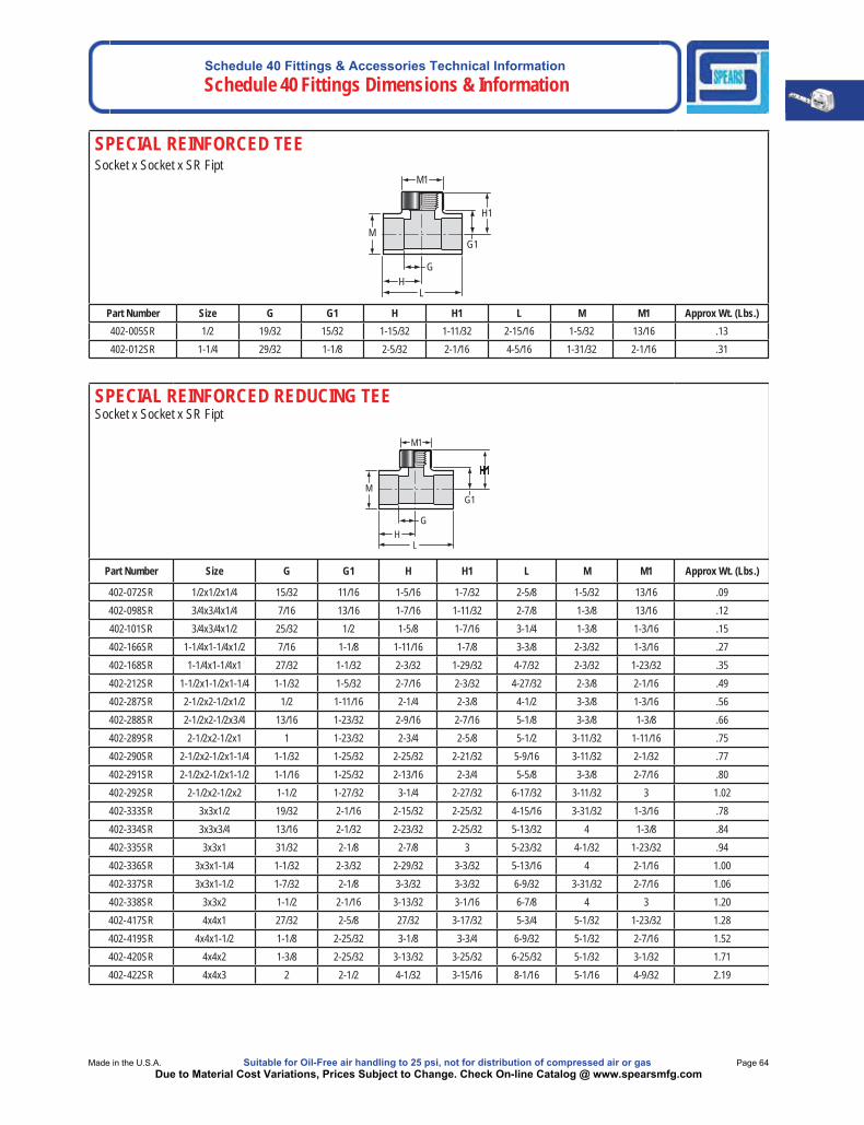
SPECIAL REINFORCED TEESocket x Socket x SR Fipt
M
H1
H G
L
G1
M1
Part Number Size G G1 H H1 L M M1 Approx Wt. (Lbs.) 402-005SR 1/2 19/32 15/32 1-15/32 1-11/32 2-15/16 1-5/32 13/16 .13402-012SR 1-1/4 29/32 1-1/8 2-5/32 2-1/16 4-5/16 1-31/32 2-1/16 .31
SPECIAL REINFORCED REDUCING TEESocket x Socket x SR Fipt
H1
M
H G
L
G1
M1
Part Number Size G G1 H H1 L M M1 Approx Wt. (Lbs.)
402-072SR 1/2x1/2x1/4 15/32 11/16 1-5/16 1-7/32 2-5/8 1-5/32 13/16 .09402-098SR 3/4x3/4x1/4 7/16 13/16 1-7/16 1-11/32 2-7/8 1-3/8 13/16 .12402-101SR 3/4x3/4x1/2 25/32 1/2 1-5/8 1-7/16 3-1/4 1-3/8 1-3/16 .15402-166SR 1-1/4x1-1/4x1/2 7/16 1-1/8 1-11/16 1-7/8 3-3/8 2-3/32 1-3/16 .27402-168SR 1-1/4x1-1/4x1 27/32 1-1/32 2-3/32 1-29/32 4-7/32 2-3/32 1-23/32 .35402-212SR 1-1/2x1-1/2x1-1/4 1-1/32 1-5/32 2-7/16 2-3/32 4-27/32 2-3/8 2-1/16 .49402-287SR 2-1/2x2-1/2x1/2 1/2 1-11/16 2-1/4 2-3/8 4-1/2 3-3/8 1-3/16 .56402-288SR 2-1/2x2-1/2x3/4 13/16 1-23/32 2-9/16 2-7/16 5-1/8 3-3/8 1-3/8 .66402-289SR 2-1/2x2-1/2x1 1 1-23/32 2-3/4 2-5/8 5-1/2 3-11/32 1-11/16 .75402-290SR 2-1/2x2-1/2x1-1/4 1-1/32 1-25/32 2-25/32 2-21/32 5-9/16 3-11/32 2-1/32 .77402-291SR 2-1/2x2-1/2x1-1/2 1-1/16 1-25/32 2-13/16 2-3/4 5-5/8 3-3/8 2-7/16 .80402-292SR 2-1/2x2-1/2x2 1-1/2 1-27/32 3-1/4 2-27/32 6-17/32 3-11/32 3 1.02402-333SR 3x3x1/2 19/32 2-1/16 2-15/32 2-25/32 4-15/16 3-31/32 1-3/16 .78402-334SR 3x3x3/4 13/16 2-1/32 2-23/32 2-25/32 5-13/32 4 1-3/8 .84402-335SR 3x3x1 31/32 2-1/8 2-7/8 3 5-23/32 4-1/32 1-23/32 .94402-336SR 3x3x1-1/4 1-1/32 2-3/32 2-29/32 3-3/32 5-13/16 4 2-1/16 1.00402-337SR 3x3x1-1/2 1-7/32 2-1/8 3-3/32 3-3/32 6-9/32 3-31/32 2-7/16 1.06402-338SR 3x3x2 1-1/2 2-1/16 3-13/32 3-1/16 6-7/8 4 3 1.20402-417SR 4x4x1 27/32 2-5/8 27/32 3-17/32 5-3/4 5-1/32 1-23/32 1.28402-419SR 4x4x1-1/2 1-1/8 2-25/32 3-1/8 3-3/4 6-9/32 5-1/32 2-7/16 1.52402-420SR 4x4x2 1-3/8 2-25/32 3-13/32 3-25/32 6-25/32 5-1/32 3-1/32 1.71402-422SR 4x4x3 2 2-1/2 4-1/32 3-15/16 8-1/16 5-1/16 4-9/32 2.19
Schedule 40 Fittings & Accessories Technical Information Schedule 40 Fittings Dimensions & Information
Page 65 Suitable for Oil-Free air handling to 25 psi, not for distribution of compressed air or gas Spears® Manufacturing CompanyDue to Material Cost Variations, Prices Subject to Change. Check On-line Catalog @ www.spearsmfg.com
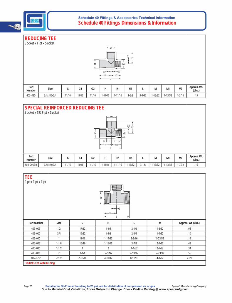
REDUCING TEESocket x Fipt x Socket
M
M1
M2
G G2H H2
H1G1
L
Part Number Size G G1 G2 H H1 H2 L M M1 M2 Approx. Wt.
(Lbs.)403-095 3/4x1/2x3/4 11/16 11/16 11/16 1-11/16 1-11/16 1-3/8 3-3/32 1-13/32 1-13/32 1-3/16 .15
SPECIAL REINFORCED REDUCING TEESocket x SR Fipt x Socket
M
M1
M2
G G2H H2
H1G1
L
Part Number Size G G1 G2 H H1 H2 L M M1 M2 Approx. Wt.
(Lbs.)403-095SR 3/4x1/2x3/4 11/16 11/16 11/16 1-11/16 1-11/16 1-13/32 3-1/8 1-13/32 1-13/32 1-7/32 .16
TEEFipt x Fipt x Fipt
M
HG
L
Part Number Size G H L M Approx. Wt. (Lbs.)
405-005 1/2 17/32 1-1/4 2-1/2 1-3/32 .08405-007 3/4 19/32 1-3/8 2-3/4 1-9/32 .10405-010 1 11/16 1-19/32 3-3/16 1-23/32 .19405-012 1-1/4 15/16 1-15/16 3-7/8 2-7/32 .48405-015 1-1/2 1 2 4-1/32 2-7/32 .34405-020 2 1-1/4 2-5/16 4-19/32 2-23/32 .56405-0251 2-1/2 2-13/16 4-11/32 8-11/16 4-1/32 2.89
1 Outlet sized with bushing

Schedule 40 Fittings & Accessories Technical InformationSchedule 40 Fittings Dimensions & Information
Made in the U.S.A. Suitable for Oil-Free air handling to 25 psi, not for distribution of compressed air or gas Page 66Due to Material Cost Variations, Prices Subject to Change. Check On-line Catalog @ www.spearsmfg.com
VENTURIED TEE1" Socket x 3/4" Socket (1" Spigot) x 3/4" Socket (1" Spigot)
M
M1
M2
G G2H H2
H1G1
Part Number Size G G1 G2 H H1 H2 M M1 M2 Approx. Wt. (Lbs.)
473-825 1x3/4x3/4 19/32 27/32 3/4 1-1/2 1-11/16 1-25/32 1-5/8 1-5/16 1-5/16 .15
MANIFOLD TEESpigot x Socket x Mipt
M2H1
G1
PIPE O.D.
LH2
G2HG
Part Number Size G G1 G2 H H1 H2 L M2 Approx. Wt. (Lbs.)
476-010 1 1-23/32 1-11/32 1-11/16 2-5/8 2-5/32 2-5/8 5-1/4 1-21/32 .24
MANIFOLD TEESpigot x Socket x Fipt
M1
M2
H1G1
G2H2
L
PIPE O.D.
GH
Part Number Size G G1 G2 H H1 H2 L M1 M2 Approx. Wt. (Lbs.)477-010 1 1-23/32 1-1/4 1-11/16 2-5/8 2-5/32 2-5/8 5-1/4 1-21/32 1-21/32 .27
O-RING SEALED MANIFOLD TEEO-ring Sealed Mipt x Fipt x Mipt
Part Number Size G G1 G2 H H1 H2 L M Approx. Wt. (Lbs.)
451A-010 1 2-19/32 31/32 3/4 3-13/16 1-31/32 1-11/16 5-1/2 1-21/32 .19
M
H1G1
G2H2
L
GH
Schedule 40 Fittings & Accessories Technical Information Schedule 40 Fittings Dimensions & Information
Page 67 Suitable for Oil-Free air handling to 25 psi, not for distribution of compressed air or gas Spears® Manufacturing CompanyDue to Material Cost Variations, Prices Subject to Change. Check On-line Catalog @ www.spearsmfg.com
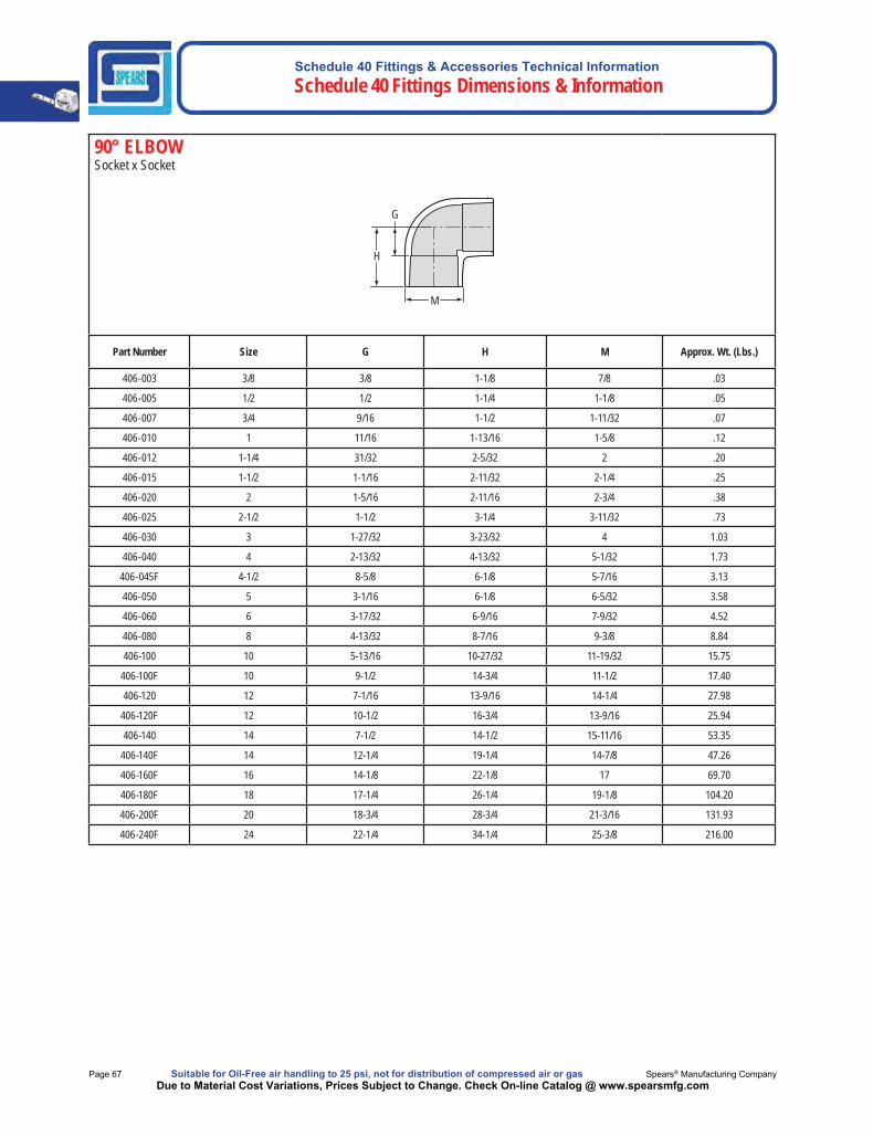
90° ELBOW Socket x Socket
H
M
G
Part Number Size G H M Approx. Wt. (Lbs.)
406-003 3/8 3/8 1-1/8 7/8 .03
406-005 1/2 1/2 1-1/4 1-1/8 .05
406-007 3/4 9/16 1-1/2 1-11/32 .07
406-010 1 11/16 1-13/16 1-5/8 .12
406-012 1-1/4 31/32 2-5/32 2 .20
406-015 1-1/2 1-1/16 2-11/32 2-1/4 .25
406-020 2 1-5/16 2-11/16 2-3/4 .38
406-025 2-1/2 1-1/2 3-1/4 3-11/32 .73
406-030 3 1-27/32 3-23/32 4 1.03
406-040 4 2-13/32 4-13/32 5-1/32 1.73
406-045F 4-1/2 8-5/8 6-1/8 5-7/16 3.13
406-050 5 3-1/16 6-1/8 6-5/32 3.58
406-060 6 3-17/32 6-9/16 7-9/32 4.52
406-080 8 4-13/32 8-7/16 9-3/8 8.84
406-100 10 5-13/16 10-27/32 11-19/32 15.75
406-100F 10 9-1/2 14-3/4 11-1/2 17.40
406-120 12 7-1/16 13-9/16 14-1/4 27.98
406-120F 12 10-1/2 16-3/4 13-9/16 25.94
406-140 14 7-1/2 14-1/2 15-11/16 53.35
406-140F 14 12-1/4 19-1/4 14-7/8 47.26
406-160F 16 14-1/8 22-1/8 17 69.70
406-180F 18 17-1/4 26-1/4 19-1/8 104.20
406-200F 20 18-3/4 28-3/4 21-3/16 131.93
406-240F 24 22-1/4 34-1/4 25-3/8 216.00
Schedule 40 Fittings & Accessories Technical InformationSchedule 40 Fittings Dimensions & Information
Made in the U.S.A. Suitable for Oil-Free air handling to 25 psi, not for distribution of compressed air or gas Page 68Due to Material Cost Variations, Prices Subject to Change. Check On-line Catalog @ www.spearsmfg.com
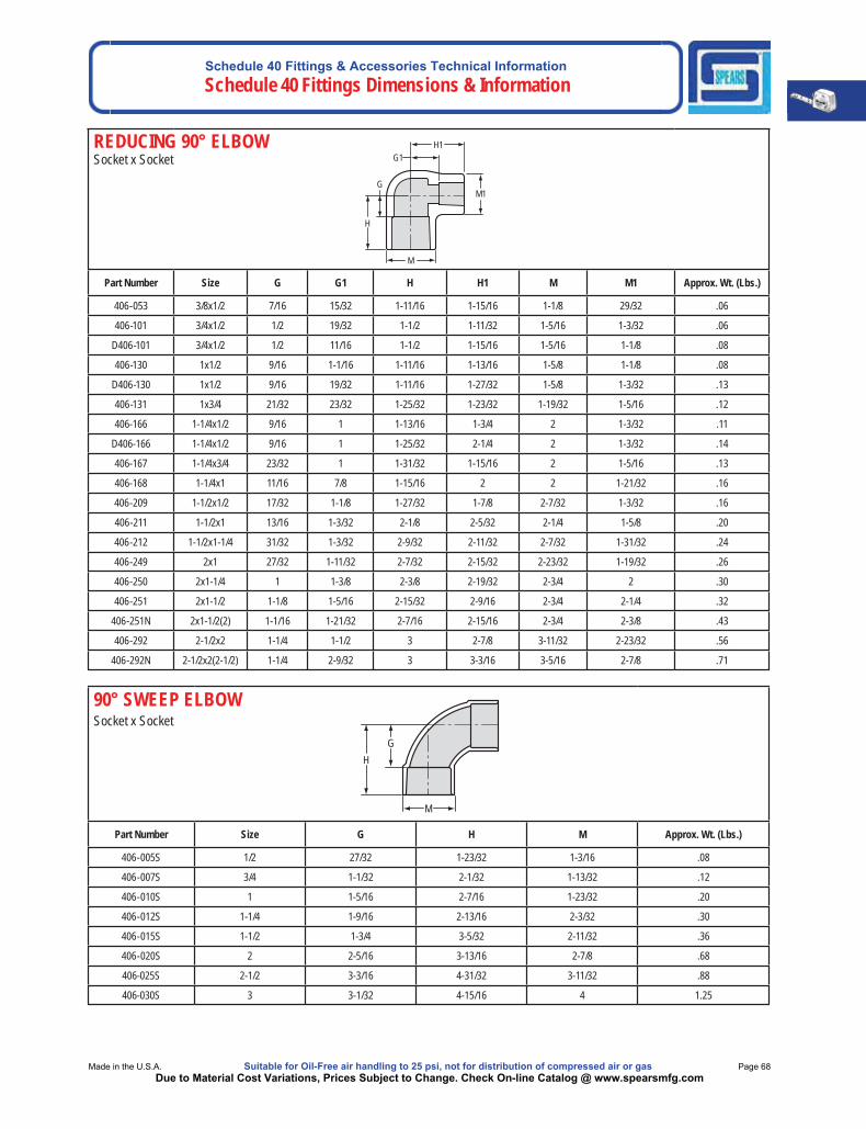
REDUCING 90° ELBOWSocket x Socket
Part Number Size G G1 H H1 M M1 Approx. Wt. (Lbs.)
406-053 3/8x1/2 7/16 15/32 1-11/16 1-15/16 1-1/8 29/32 .06
406-101 3/4x1/2 1/2 19/32 1-1/2 1-11/32 1-5/16 1-3/32 .06
D406-101 3/4x1/2 1/2 11/16 1-1/2 1-15/16 1-5/16 1-1/8 .08
406-130 1x1/2 9/16 1-1/16 1-11/16 1-13/16 1-5/8 1-1/8 .08
D406-130 1x1/2 9/16 19/32 1-11/16 1-27/32 1-5/8 1-3/32 .13
406-131 1x3/4 21/32 23/32 1-25/32 1-23/32 1-19/32 1-5/16 .12
406-166 1-1/4x1/2 9/16 1 1-13/16 1-3/4 2 1-3/32 .11
D406-166 1-1/4x1/2 9/16 1 1-25/32 2-1/4 2 1-3/32 .14
406-167 1-1/4x3/4 23/32 1 1-31/32 1-15/16 2 1-5/16 .13
406-168 1-1/4x1 11/16 7/8 1-15/16 2 2 1-21/32 .16
406-209 1-1/2x1/2 17/32 1-1/8 1-27/32 1-7/8 2-7/32 1-3/32 .16
406-211 1-1/2x1 13/16 1-3/32 2-1/8 2-5/32 2-1/4 1-5/8 .20
406-212 1-1/2x1-1/4 31/32 1-3/32 2-9/32 2-11/32 2-7/32 1-31/32 .24
406-249 2x1 27/32 1-11/32 2-7/32 2-15/32 2-23/32 1-19/32 .26
406-250 2x1-1/4 1 1-3/8 2-3/8 2-19/32 2-3/4 2 .30
406-251 2x1-1/2 1-1/8 1-5/16 2-15/32 2-9/16 2-3/4 2-1/4 .32
406-251N 2x1-1/2(2) 1-1/16 1-21/32 2-7/16 2-15/16 2-3/4 2-3/8 .43
406-292 2-1/2x2 1-1/4 1-1/2 3 2-7/8 3-11/32 2-23/32 .56
406-292N 2-1/2x2(2-1/2) 1-1/4 2-9/32 3 3-3/16 3-5/16 2-7/8 .71
H1 G1
M1
H
G
M
90° SWEEP ELBOWSocket x Socket
Part Number Size G H M Approx. Wt. (Lbs.)
406-005S 1/2 27/32 1-23/32 1-3/16 .08
406-007S 3/4 1-1/32 2-1/32 1-13/32 .12
406-010S 1 1-5/16 2-7/16 1-23/32 .20
406-012S 1-1/4 1-9/16 2-13/16 2-3/32 .30
406-015S 1-1/2 1-3/4 3-5/32 2-11/32 .36
406-020S 2 2-5/16 3-13/16 2-7/8 .68
406-025S 2-1/2 3-3/16 4-31/32 3-11/32 .88
406-030S 3 3-1/32 4-15/16 4 1.25
M
GH
Schedule 40 Fittings & Accessories Technical Information Schedule 40 Fittings Dimensions & Information
Page 69 Suitable for Oil-Free air handling to 25 psi, not for distribution of compressed air or gas Spears® Manufacturing CompanyDue to Material Cost Variations, Prices Subject to Change. Check On-line Catalog @ www.spearsmfg.com
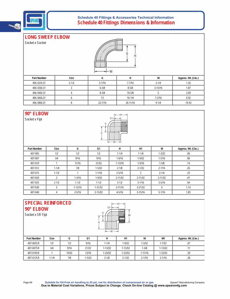
LONG SWEEP ELBOWSocket x Socket
Part Number Size G H M Approx. Wt. (Lbs.)406-025LSF 2-1/2 5-7/16 7-7/16 3-1/4 1.26406-030LSF 3 6-3/8 8-5/8 3-15/16 1.87406-040LSF 4 8-3/8 10-5/8 5 2.69406-060LSF 6 13 16-1/4 7-3/16 6.92406-080LSF 8 22-7/16 26-11/16 9-1/4 19.43
M
GH
90° ELBOWSocket x Fipt
Part Number Size G G1 H H1 M Approx. Wt. (Lbs.)407-005 1/2 1/2 1/2 1-1/4 1-1/4 1-3/32 .06407-007 3/4 9/16 9/16 1-9/16 1-9/32 1-5/16 .08407-010 1 11/16 21/32 1-13/16 1-9/16 1-5/8 .14407-012 1-1/4 7/8 1-5/32 2-1/8 2-1/32 2-1/16 .26407-015 1-1/2 1 1-1/16 2-5/16 2 2-1/4 .25407-020 2 1-3/16 1-9/32 2-11/32 2-11/32 2-11/32 .47407-025 2-1/2 1-1/2 1-1/2 3-1/2 3-1/16 3-5/16 .94407-030 3 1-13/16 1-31/32 3-11/16 3-21/32 4 1.14407-040 4 2-5/16 2-15/32 4-5/16 3-15/16 5-1/16 1.85
G
G1
H
H1
M
SPECIAL REINFORCED 90° ELBOWSocket x SR Fipt
Part Number Size G G1 H H1 M M1 Approx. Wt. (Lbs.)407-005SR 1/2 1/2 9/16 1-1/4 1-9/32 1-3/32 1-7/32 .07407-007SR 3/4 9/16 21/32 1-13/32 1-13/32 1-3/8 1-13/32 .11407-010SR 1 19/32 13/16 1-23/32 1-23/32 1-11/16 1-23/32 .20407-012SR 1-1/4 7/8 1-5/32 2-1/8 2-1/32 2-1/16 2-1/16 .28
M
H
H1
G
G1
M1

Schedule 40 Fittings & Accessories Technical InformationSchedule 40 Fittings Dimensions & Information
Made in the U.S.A. Suitable for Oil-Free air handling to 25 psi, not for distribution of compressed air or gas Page 70Due to Material Cost Variations, Prices Subject to Change. Check On-line Catalog @ www.spearsmfg.com
REDUCING 90° ELBOWSocket x Fipt
H
M1
M
H1 G1
G
Part Number Size G G1 H H1 M M1 Approx. Wt. (Lbs.)
407-053 3/8x1/2 17/32 17/32 1-9/32 1-9/32 7/8 1-3/32 .04
407-074 1/2x3/4 21/32 9/16 1-13/32 1-11/32 1-5/16 1-3/32 .07
407-101 3/4x1/2 9/16 5/8 1-1/2 1-3/8 1-5/16 1-3/32 .07
407-130 1x1/2 7/16 11/16 1-9/16 1-7/16 1-5/8 1-3/32 .10
407-131 1x3/4 11/16 7/8 1-13/16 1-5/8 1-5/8 1-5/16 .11
407-168 1-1/4x1 1 1-1/32 2-1/4 2 2 1-5/8 .19
407-211 1-1/2x1 13/16 1-1/8 2-3/32 2 2-1/4 1-11/16 .23
407-212 1-1/2x1-1/4 15/16 1-1/4 2-1/4 2-7/32 2-3/16 1-15/16 .24
407-249 2x1 13/16 1-9/16 2-5/16 2-3/8 2-3/4 1-11/16 .31
407-250 2x1-1/4 1 1-1/4 2-3/8 2-7/32 2-3/4 2 .31
407-251 2x1-1/2 1-1/8 1-9/16 2-1/2 2-1/2 2-23/32 2-13/32 .42
SPECIAL REINFORCED REDUCING 90° ELBOWSocket x SR Fipt
H
M1
M
H1 G1
G
Part Number Size G G1 H H1 M M1 Approx. Wt. (Lbs.)
407-211SR 1-1/2x1 13/16 1-1/8 2-3/32 2 2-1/4 21-11/16 .24
407-249SR 2x1 1-3/16 1-9/16 2-5/16 2-3/8 2-3/4 1-1/16 .33
407-251SR 2x1-1/2 1-1/8 1-19/32 2-1/2 2-17/32 2-23/32 2-7/16 .45
Schedule 40 Fittings & Accessories Technical Information Schedule 40 Fittings Dimensions & Information
Page 71 Suitable for Oil-Free air handling to 25 psi, not for distribution of compressed air or gas Spears® Manufacturing CompanyDue to Material Cost Variations, Prices Subject to Change. Check On-line Catalog @ www.spearsmfg.com
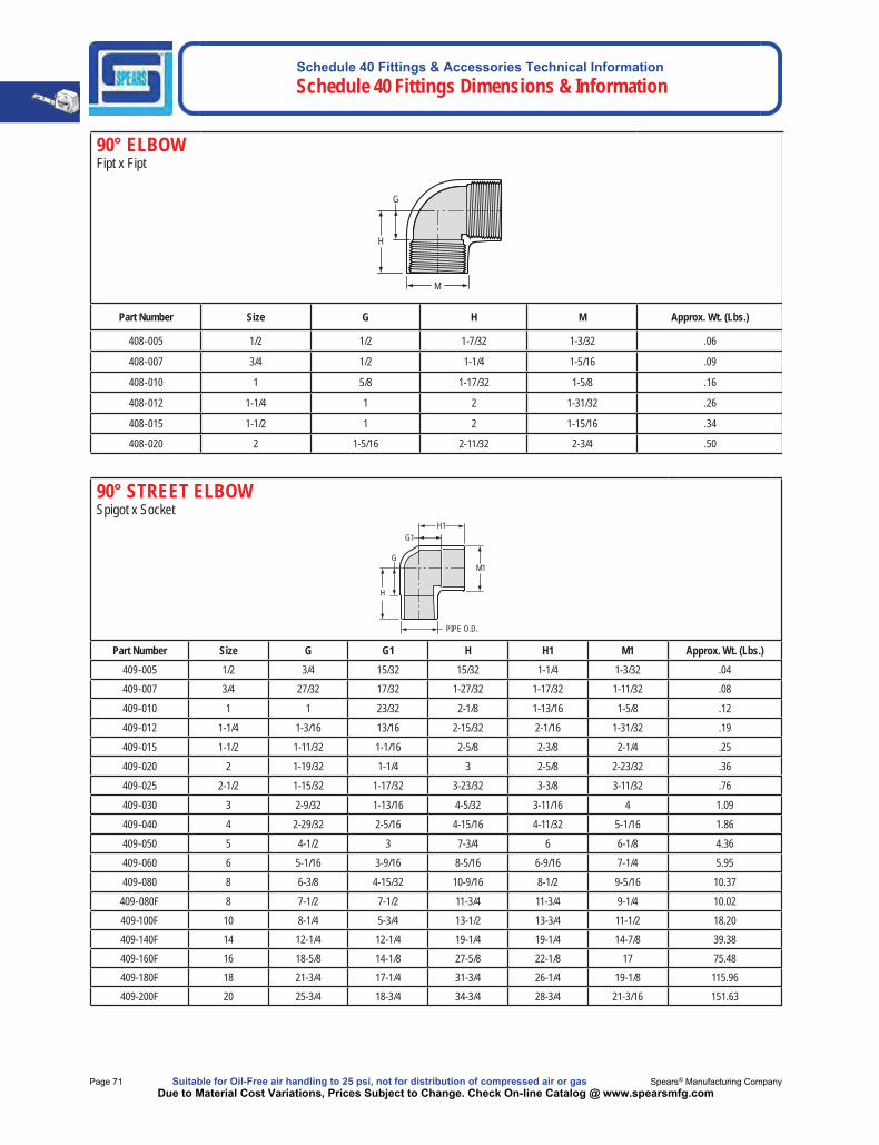
90° ELBOWFipt x Fipt
M
H
G
Part Number Size G H M Approx. Wt. (Lbs.)
408-005 1/2 1/2 1-7/32 1-3/32 .06
408-007 3/4 1/2 1-1/4 1-5/16 .09
408-010 1 5/8 1-17/32 1-5/8 .16
408-012 1-1/4 1 2 1-31/32 .26
408-015 1-1/2 1 2 1-15/16 .34
408-020 2 1-5/16 2-11/32 2-3/4 .50
90° STREET ELBOW Spigot x Socket
PIPE O.D.
H1 G1
G
H
M1
Part Number Size G G1 H H1 M1 Approx. Wt. (Lbs.)409-005 1/2 3/4 15/32 15/32 1-1/4 1-3/32 .04
409-007 3/4 27/32 17/32 1-27/32 1-17/32 1-11/32 .08
409-010 1 1 23/32 2-1/8 1-13/16 1-5/8 .12
409-012 1-1/4 1-3/16 13/16 2-15/32 2-1/16 1-31/32 .19
409-015 1-1/2 1-11/32 1-1/16 2-5/8 2-3/8 2-1/4 .25
409-020 2 1-19/32 1-1/4 3 2-5/8 2-23/32 .36
409-025 2-1/2 1-15/32 1-17/32 3-23/32 3-3/8 3-11/32 .76
409-030 3 2-9/32 1-13/16 4-5/32 3-11/16 4 1.09
409-040 4 2-29/32 2-5/16 4-15/16 4-11/32 5-1/16 1.86
409-050 5 4-1/2 3 7-3/4 6 6-1/8 4.36
409-060 6 5-1/16 3-9/16 8-5/16 6-9/16 7-1/4 5.95
409-080 8 6-3/8 4-15/32 10-9/16 8-1/2 9-5/16 10.37
409-080F 8 7-1/2 7-1/2 11-3/4 11-3/4 9-1/4 10.02
409-100F 10 8-1/4 5-3/4 13-1/2 13-3/4 11-1/2 18.20409-140F 14 12-1/4 12-1/4 19-1/4 19-1/4 14-7/8 39.38409-160F 16 18-5/8 14-1/8 27-5/8 22-1/8 17 75.48409-180F 18 21-3/4 17-1/4 31-3/4 26-1/4 19-1/8 115.96409-200F 20 25-3/4 18-3/4 34-3/4 28-3/4 21-3/16 151.63

Schedule 40 Fittings & Accessories Technical InformationSchedule 40 Fittings Dimensions & Information
Made in the U.S.A. Suitable for Oil-Free air handling to 25 psi, not for distribution of compressed air or gas Page 72Due to Material Cost Variations, Prices Subject to Change. Check On-line Catalog @ www.spearsmfg.com
90° STREET ELBOW Mipt x Socket
H1G1
H
GM1
Part Number Size G G1 H H1 M1 Approx. Wt. (Lbs.)410-005 1/2 21/32 3/8 1-11/32 1-5/32 1-3/32 .04
410-007 3/4 27/32 15/32 1-17/32 1-15/32 1-5/16 .08
410-010 1 1-1/32 11/16 1-29/32 1-13/16 1-5/8 .13
410-012 1-1/4 1-3/16 3/4 2-3/32 2 2 .18
410-015 1-1/2 1-13/32 1 2-13/32 2-5/16 2-7/32 .40
410-020 2 1-5/8 1-11/32 2-9/16 2-23/32 2-23/32 .41
410-030 3 2-11/16 1-27/32 3-31/32 3-23/32 4 1.22
REDUCING 90° STREET ELBOW Mipt x Socket
M1
H1G1
G
H
Part Number Size G G1 H H1 M1 Approx. Wt. (Lbs.)410-101 3/4x1/2 23/32 13/32 1-7/16 1-1/4 1-3/32 .06
410-102 3/4x1 3/4 1/2 1-3/4 1-11/32 1-5/8 .09
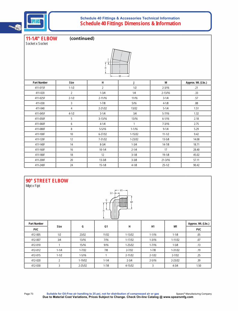
11-1/4° ELBOW Socket x Socket
M
H
J
Part Number Size H J M Approx. Wt. (Lbs.)411-005F 1/2 1-5/16 5/16 1-1/16 .05411-007F 3/4 1-5/16 5/16 1-1/4 .07411-010F 1 1-9/16 5/16 1-9/16 .10411-012F 1-1/4 2 1/2 1-5/16 .21411-015 1-1/2 1-19/32 7/32 2-3/8 .24
Schedule 40 Fittings & Accessories Technical Information Schedule 40 Fittings Dimensions & Information
Page 73 Suitable for Oil-Free air handling to 25 psi, not for distribution of compressed air or gas Spears® Manufacturing CompanyDue to Material Cost Variations, Prices Subject to Change. Check On-line Catalog @ www.spearsmfg.com
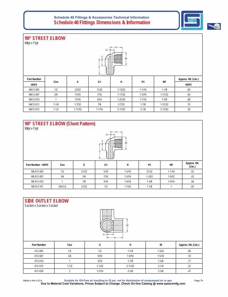
90° STREET ELBOWMipt x Fipt
M1 G
H
G1 H1
Part NumberSize G G1 H H1 M1
Approx. Wt. (Lbs.)
PVC PVC412-005 1/2 23/32 11/32 1-13/32 1-1/16 1-1/8 .05412-007 3/4 13/16 7/16 1-17/32 1-3/16 1-11/32 .07412-010 1 15/16 9/16 1-25/32 1-7/16 1-5/8 .13412-012 1-1/4 1-7/32 7/8 2-7/32 1-7/8 1-31/32 .19412-015 1-1/2 1-5/16 1 2-11/32 2-1/32 2-7/32 .25412-020 2 1-19/32 1-1/4 2-3/4 2-5/16 2-23/32 .39412-030 3 2-25/32 1-7/8 4-15/32 3 4-3/4 1.50
11-1/4° ELBOW Socket x Socket
M
H
J
Part Number Size H J M Approx. Wt. (Lbs.)411-015F 1-1/2 2 1/2 2-3/16 .21411-020 2 1-3/4 1/4 2-13/16 .33
411-025F 2-1/2 2-11/16 11/16 3-1/4 .57411-030 3 1-7/8 5/16 4-1/8 .88411-040 4 2-21/32 13/32 5-1/4 1.51
411-045F 4-1/2 3-1/4 3/4 5-7/16 1.32411-050F 5 3-13/16 13/16 6-1/16 2.18411-060F 6 4-1/4 1 7-3/16 2.75411-080F 8 5-5/16 1-1/16 9-1/4 5.29411-100F 10 6-27/32 1-15/32 11-1/2 9.42411-120F 12 7-31/32 1-23/32 13-5/8 14.08411-140F 14 8-3/4 1-3/4 14-7/8 18.71411-160F 16 10-1/4 2-1/4 17 28.40411-180F 18 12 3-1/8 19-1/8 45.02411-200F 20 13-3/8 3-3/8 21-3/16 57.11411-240F 24 15-1/8 4-1/8 25-1/2 90.42
Schedule 40 Fittings & Accessories Technical InformationSchedule 40 Fittings Dimensions & Information
Made in the U.S.A. Suitable for Oil-Free air handling to 25 psi, not for distribution of compressed air or gas Page 74Due to Material Cost Variations, Prices Subject to Change. Check On-line Catalog @ www.spearsmfg.com
90° STREET ELBOW (Short Pattern)Mipt x Fipt
M1 G
H
G1 H1
Part Number - HDPE Size G G1 H H1 M1 Approx. Wt. (Lbs.)
MS412-005 1/2 21/32 5/16 1-3/16 31/32 1-1/16 .02
MS412-007 3/4 3/4 7/16 1-5/16 1-3/32 1-9/32 .03
MS412-010 1 7/8 9/16 1-9/16 1-3/8 1-9/16 .06
MS412-101 3/4x1/2 21/32 1/2 1-7/32 1-1/8 1 .03
SIDE OUTLET ELBOWSocket x Socket x Socket
H G
M
Part Number Size G H M Approx. Wt. (Lbs.)
413-005 1/2 1/2 1-1/4 1-3/32 .06
413-007 3/4 9/16 1-9/16 1-5/16 .10
413-010 1 3/16 1-7/8 1-5/8 .17
413-015 1-1/2 1-1/32 2-11/32 2-1/4 .32
413-020 2 1-5/16 2-5/8 2-3/4 .47
90° STREET ELBOWMipt x Fipt
M1 G
H
G1 H1
Part NumberSize G G1 H H1 M1
Approx. Wt. (Lbs.)
HDPE HDPEM412-005 1/2 23/32 11/32 1-13/32 1-1/16 1-1/8 .04M412-007 3/4 13/16 7/16 1-17/32 1-3/16 1-11/32 .04M412-010 1 15/16 9/16 1-25/32 1-7/16 1-5/8 .08M412-012 1-1/4 1-7/32 7/8 2-7/32 1-7/8 1-31/32 .15M412-015 1-1/2 1-11/32 1-1/16 2-11/32 2-1/8 2-13/32 .20

Schedule 40 Fittings & Accessories Technical Information Schedule 40 Fittings Dimensions & Information
Page 75 Suitable for Oil-Free air handling to 25 psi, not for distribution of compressed air or gas Spears® Manufacturing CompanyDue to Material Cost Variations, Prices Subject to Change. Check On-line Catalog @ www.spearsmfg.com
30° ELBOW Socket x Socket
H
J
M
Part Number Size H J M Approx. Wt. (Lbs.)415-005F 1/2 1-3/8 3/8 1-1/16 0.04
415-007F 3/4 1-7/16 7/16 1-1/4 0.07
415-010F 1 1-3/4 1/2 1-9/16 0.12
415-012F 1-1/4 2-1/8 5/8 1-15/16 0.17
415-015F 1-1/2 2-3/16 11/16 2-3/16 0.19
415-020F 2 2-1/2 3/4 2-11/16 0.34
415-025F 2-1/2 2-15/16 15/16 3-1/4 0.62
415-030F 3 3-5/16 1-1/16 3-15/16 0.93
415-040F 4 3-7/16 1-3/16 5 1.39
415-045F 4-1/2 3-3/4 1-1/4 5-7/16 1.48
415-050F 5 4-5/16 1-5/16 6-1/16 2.27
415-060F 6 4-7/8 1-5/8 7-3/16 3.25
415-080F 8 6-1/8 1-7/8 9-1/4 5.40
415-100F 10 7-1/4 2 11-1/2 10.67
415-120F 12 9-5/16 2-9/16 13-1/2 16.56
415-140F 14 9-3/4 2-3/4 14-7/8 20.68
415-160F 16 11-7/8 3-7/8 17 32.27
415-180F 18 13-1/2 4-1/2 19-1/8 48.74
415-200F 20 15-1/4 5-1/4 21-1/4 63.01
415-240F 24 17 6 25-1/2 104.12
SIDE OUTLET ELBOWSocket x Socket x Fipt
M1
M
HG
H1
G1
Part Number Size G G1 H H1 M M1 Approx. Wt. (Lbs.)414-005 1/2 1/2 1/2 1-1/4 1-1/4 1-3/32 1-3/32 .07
414-007 3/4 9/16 5/8 1-9/16 1-7/16 1-9/32 1-9/32 .10
414-101 3/4x3/4x1/2 9/16 21/32 1-9/16 1-13/32 1-5/16 1-1/16 .09
414-130 1x1x1/2 11/16 13/16 1-13/16 1-9/16 1-5/8 1-1/16 .14
Schedule 40 Fittings & Accessories Technical InformationSchedule 40 Fittings Dimensions & Information
Made in the U.S.A. Suitable for Oil-Free air handling to 25 psi, not for distribution of compressed air or gas Page 76Due to Material Cost Variations, Prices Subject to Change. Check On-line Catalog @ www.spearsmfg.com
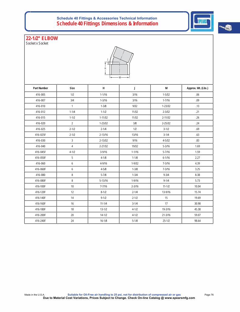
22-1/2° ELBOW Socket x Socket
M
H
J
Part Number Size H J M Approx. Wt. (Lbs.)
416-005 1/2 1-1/16 3/16 1-5/32 .06
416-007 3/4 1-3/16 3/16 1-7/16 .09
416-010 1 1-3/8 9/32 1-23/32 .13
416-012 1-1/4 1-1/2 11/32 2-3/32 .21
416-015 1-1/2 1-11/32 11/32 2-11/32 .26
416-020 2 1-23/32 3/8 2-25/32 .24
416-025 2-1/2 2-1/4 1/2 3-1/2 .69
416-025F 2-1/2 2-13/16 13/16 3-1/4 .63
416-030 3 2-13/32 9/16 4-5/32 .83
416-040 4 2-27/32 19/32 5-3/16 1.69
416-045F 4-1/2 3-9/16 1-1/16 5-7/16 1.59
416-050F 5 4-1/8 1-1/8 6-1/16 2.27
416-060 6 4-9/16 1-9/32 7-3/16 4.39
416-060F 6 4-5/8 1-3/8 7-3/16 3.25
416-080 8 5-7/8 1-3/4 9-3/4 8.38
416-080F 8 5-13/16 1-9/16 9-1/4 5.73
416-100F 10 7-7/16 2-3/16 11-1/2 10.04
416-120F 12 8-1/2 2-1/4 13-9/16 15.74
416-140F 14 9-1/2 2-1/2 15 19.69
416-160F 16 11-1/4 3-1/4 17 30.98
416-180F 18 13-1/2 4-1/2 19-3/16 45.38
416-200F 20 14-1/2 4-1/2 21-3/16 59.07
416-240F 24 16-1/8 5-1/8 25-1/2 98.64
Schedule 40 Fittings & Accessories Technical Information Schedule 40 Fittings Dimensions & Information
Page 77 Suitable for Oil-Free air handling to 25 psi, not for distribution of compressed air or gas Spears® Manufacturing CompanyDue to Material Cost Variations, Prices Subject to Change. Check On-line Catalog @ www.spearsmfg.com
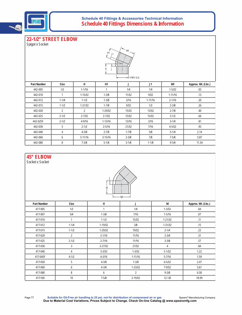
22-1/2° STREET ELBOWSpigot x Socket
PIPE O.D.
M1
H
H1
J
J1
Part Number Size H H1 J J1 M1 Approx. Wt. (Lbs.)442-005 1/2 1-1/16 1 1/4 1/4 1-5/32 .05
442-010 1 1-15/32 1-3/8 11/32 9/32 1-11/16 .13
442-012 1-1/4 1-1/2 1-3/8 3/16 1-11/16 2-1/16 .20
442-015 1-1/2 1-21/32 1-7/8 9/32 1/2 2-3/8 .26
442-020 2 2 1-29/32 15/32 13/32 2-7/8 .40
442-025 2-1/2 2-7/32 2-7/32 15/32 15/32 3-1/2 .66
442-025F 2-1/2 4-9/16 1-13/16 13/16 3/16 3-1/4 .81
442-030 3 2-1/2 2-5/16 21/32 7/16 4-5/32 .95
442-040 4 4-3/8 2-7/8 1-7/8 5/8 5-1/4 2.14
442-060 6 5-11/16 3-15/16 2-3/8 7/8 7-5/8 5.87
442-080 8 7-3/8 5-1/8 3-1/8 1-1/8 9-3/4 11.34
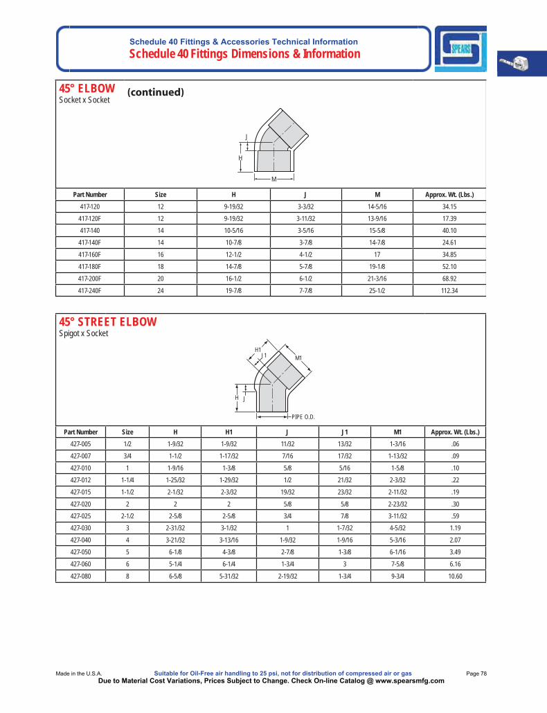
45° ELBOWSocket x Socket
M
H
J
Part Number Size H J M Approx. Wt. (Lbs.)417-005 1/2 1 1/4 1-3/32 .04
417-007 3/4 1-3/8 7/16 1-5/16 .07
417-010 1 1-1/2 15/32 1-21/32 .11
417-012 1-1/4 1-19/32 3/8 1-31/32 .15
417-015 1-1/2 1-29/32 19/32 2-1/4 .22
417-020 2 2-1/16 11/16 2-3/4 .31
417-025 2-1/2 2-7/16 11/16 3-3/8 .57
417-030 3 2-27/32 27/32 4 .84
417-040 4 3-3/32 1-3/32 5-1/32 1.22
417-045F 4-1/2 4-3/16 1-11/16 5-7/16 1.59
417-050 5 4-3/8 1-3/8 6-5/32 2.47
417-060 6 4-3/4 1-23/32 7-9/32 3.61
417-080 8 6 2 9-3/8 6.58
417-100 10 7-5/8 2-19/32 12-1/8 18.99
Schedule 40 Fittings & Accessories Technical InformationSchedule 40 Fittings Dimensions & Information
Made in the U.S.A. Suitable for Oil-Free air handling to 25 psi, not for distribution of compressed air or gas Page 78Due to Material Cost Variations, Prices Subject to Change. Check On-line Catalog @ www.spearsmfg.com
45° STREET ELBOWSpigot x Socket
J1 H1
M1
J H
PIPE O.D.
Part Number Size H H1 J J1 M1 Approx. Wt. (Lbs.)427-005 1/2 1-9/32 1-9/32 11/32 13/32 1-3/16 .06
427-007 3/4 1-1/2 1-17/32 7/16 17/32 1-13/32 .09
427-010 1 1-9/16 1-3/8 5/8 5/16 1-5/8 .10
427-012 1-1/4 1-25/32 1-29/32 1/2 21/32 2-3/32 .22
427-015 1-1/2 2-1/32 2-3/32 19/32 23/32 2-11/32 .19
427-020 2 2 2 5/8 5/8 2-23/32 .30
427-025 2-1/2 2-5/8 2-5/8 3/4 7/8 3-11/32 .59
427-030 3 2-31/32 3-1/32 1 1-7/32 4-5/32 1.19
427-040 4 3-21/32 3-13/16 1-9/32 1-9/16 5-3/16 2.07
427-050 5 6-1/8 4-3/8 2-7/8 1-3/8 6-1/16 3.49
427-060 6 5-1/4 6-1/4 1-3/4 3 7-5/8 6.16
427-080 8 6-5/8 5-31/32 2-19/32 1-3/4 9-3/4 10.60
45° ELBOWSocket x Socket
M
H
J
Part Number Size H J M Approx. Wt. (Lbs.)417-120 12 9-19/32 3-3/32 14-5/16 34.15
417-120F 12 9-19/32 3-11/32 13-9/16 17.39
417-140 14 10-5/16 3-5/16 15-5/8 40.10
417-140F 14 10-7/8 3-7/8 14-7/8 24.61
417-160F 16 12-1/2 4-1/2 17 34.85
417-180F 18 14-7/8 5-7/8 19-1/8 52.10
417-200F 20 16-1/2 6-1/2 21-3/16 68.92
417-240F 24 19-7/8 7-7/8 25-1/2 112.34
Schedule 40 Fittings & Accessories Technical Information Schedule 40 Fittings Dimensions & Information
Page 79 Suitable for Oil-Free air handling to 25 psi, not for distribution of compressed air or gas Spears® Manufacturing CompanyDue to Material Cost Variations, Prices Subject to Change. Check On-line Catalog @ www.spearsmfg.com
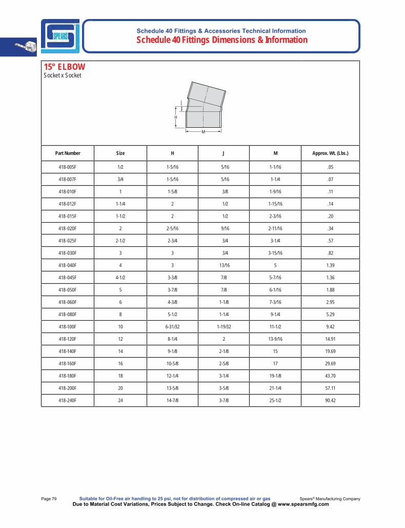
15° ELBOWSocket x Socket
M
H
J
Part Number Size H J M Approx. Wt. (Lbs.)
418-005F 1/2 1-5/16 5/16 1-1/16 .05
418-007F 3/4 1-5/16 5/16 1-1/4 .07
418-010F 1 1-5/8 3/8 1-9/16 .11
418-012F 1-1/4 2 1/2 1-15/16 .14
418-015F 1-1/2 2 1/2 2-3/16 .20
418-020F 2 2-5/16 9/16 2-11/16 .34
418-025F 2-1/2 2-3/4 3/4 3-1/4 .57
418-030F 3 3 3/4 3-15/16 .82
418-040F 4 3 13/16 5 1.39
418-045F 4-1/2 3-3/8 7/8 5-7/16 1.36
418-050F 5 3-7/8 7/8 6-1/16 1.88
418-060F 6 4-3/8 1-1/8 7-3/16 2.95
418-080F 8 5-1/2 1-1/4 9-1/4 5.29
418-100F 10 6-31/32 1-19/32 11-1/2 9.42
418-120F 12 8-1/4 2 13-9/16 14.91
418-140F 14 9-1/8 2-1/8 15 19.69
418-160F 16 10-5/8 2-5/8 17 29.69
418-180F 18 12-1/4 3-1/4 19-1/8 43.70
418-200F 20 13-5/8 3-5/8 21-1/4 57.11
418-240F 24 14-7/8 3-7/8 25-1/2 90.42
Schedule 40 Fittings & Accessories Technical InformationSchedule 40 Fittings Dimensions & Information
Made in the U.S.A. Suitable for Oil-Free air handling to 25 psi, not for distribution of compressed air or gas Page 80Due to Material Cost Variations, Prices Subject to Change. Check On-line Catalog @ www.spearsmfg.com
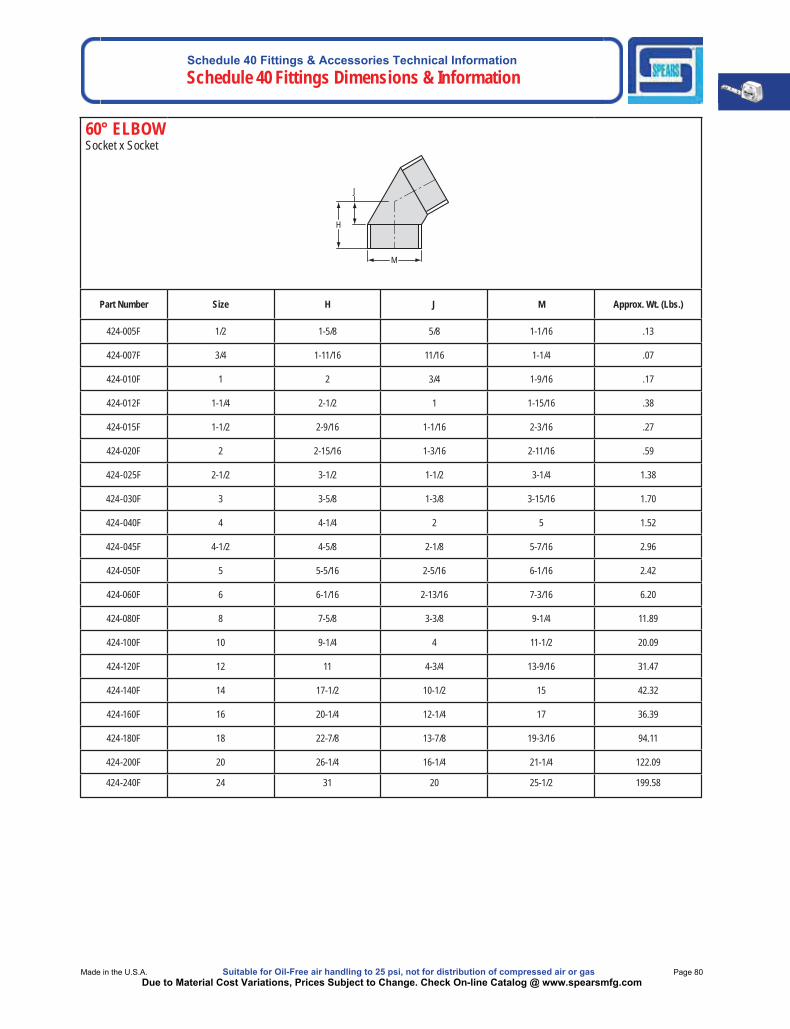
60° ELBOW Socket x Socket
H
M
J
Part Number Size H J M Approx. Wt. (Lbs.)
424-005F 1/2 1-5/8 5/8 1-1/16 .13
424-007F 3/4 1-11/16 11/16 1-1/4 .07
424-010F 1 2 3/4 1-9/16 .17
424-012F 1-1/4 2-1/2 1 1-15/16 .38
424-015F 1-1/2 2-9/16 1-1/16 2-3/16 .27
424-020F 2 2-15/16 1-3/16 2-11/16 .59
424-025F 2-1/2 3-1/2 1-1/2 3-1/4 1.38
424-030F 3 3-5/8 1-3/8 3-15/16 1.70
424-040F 4 4-1/4 2 5 1.52
424-045F 4-1/2 4-5/8 2-1/8 5-7/16 2.96
424-050F 5 5-5/16 2-5/16 6-1/16 2.42
424-060F 6 6-1/16 2-13/16 7-3/16 6.20
424-080F 8 7-5/8 3-3/8 9-1/4 11.89
424-100F 10 9-1/4 4 11-1/2 20.09
424-120F 12 11 4-3/4 13-9/16 31.47
424-140F 14 17-1/2 10-1/2 15 42.32
424-160F 16 20-1/4 12-1/4 17 36.39
424-180F 18 22-7/8 13-7/8 19-3/16 94.11
424-200F 20 26-1/4 16-1/4 21-1/4 122.09
424-240F 24 31 20 25-1/2 199.58
Schedule 40 Fittings & Accessories Technical Information Schedule 40 Fittings Dimensions & Information
Page 81 Suitable for Oil-Free air handling to 25 psi, not for distribution of compressed air or gas Spears® Manufacturing CompanyDue to Material Cost Variations, Prices Subject to Change. Check On-line Catalog @ www.spearsmfg.com
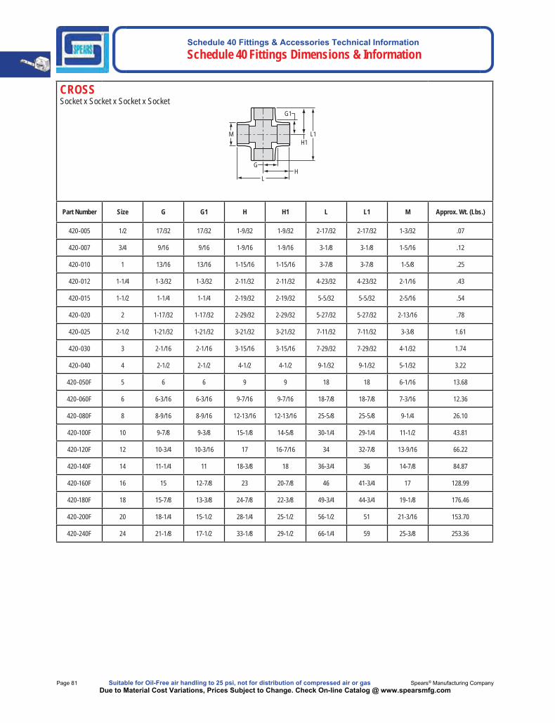
CROSSSocket x Socket x Socket x Socket
L1
L H
G
H1
G1
M
Part Number Size G G1 H H1 L L1 M Approx. Wt. (Lbs.)
420-005 1/2 17/32 17/32 1-9/32 1-9/32 2-17/32 2-17/32 1-3/32 .07
420-007 3/4 9/16 9/16 1-9/16 1-9/16 3-1/8 3-1/8 1-5/16 .12
420-010 1 13/16 13/16 1-15/16 1-15/16 3-7/8 3-7/8 1-5/8 .25
420-012 1-1/4 1-3/32 1-3/32 2-11/32 2-11/32 4-23/32 4-23/32 2-1/16 .43
420-015 1-1/2 1-1/4 1-1/4 2-19/32 2-19/32 5-5/32 5-5/32 2-5/16 .54
420-020 2 1-17/32 1-17/32 2-29/32 2-29/32 5-27/32 5-27/32 2-13/16 .78
420-025 2-1/2 1-21/32 1-21/32 3-21/32 3-21/32 7-11/32 7-11/32 3-3/8 1.61
420-030 3 2-1/16 2-1/16 3-15/16 3-15/16 7-29/32 7-29/32 4-1/32 1.74
420-040 4 2-1/2 2-1/2 4-1/2 4-1/2 9-1/32 9-1/32 5-1/32 3.22
420-050F 5 6 6 9 9 18 18 6-1/16 13.68
420-060F 6 6-3/16 6-3/16 9-7/16 9-7/16 18-7/8 18-7/8 7-3/16 12.36
420-080F 8 8-9/16 8-9/16 12-13/16 12-13/16 25-5/8 25-5/8 9-1/4 26.10
420-100F 10 9-7/8 9-3/8 15-1/8 14-5/8 30-1/4 29-1/4 11-1/2 43.81
420-120F 12 10-3/4 10-3/16 17 16-7/16 34 32-7/8 13-9/16 66.22
420-140F 14 11-1/4 11 18-3/8 18 36-3/4 36 14-7/8 84.87
420-160F 16 15 12-7/8 23 20-7/8 46 41-3/4 17 128.99
420-180F 18 15-7/8 13-3/8 24-7/8 22-3/8 49-3/4 44-3/4 19-1/8 176.46
420-200F 20 18-1/4 15-1/2 28-1/4 25-1/2 56-1/2 51 21-3/16 153.70
420-240F 24 21-1/8 17-1/2 33-1/8 29-1/2 66-1/4 59 25-3/8 253.36
Schedule 40 Fittings & Accessories Technical InformationSchedule 40 Fittings Dimensions & Information
Made in the U.S.A. Suitable for Oil-Free air handling to 25 psi, not for distribution of compressed air or gas Page 82Due to Material Cost Variations, Prices Subject to Change. Check On-line Catalog @ www.spearsmfg.com
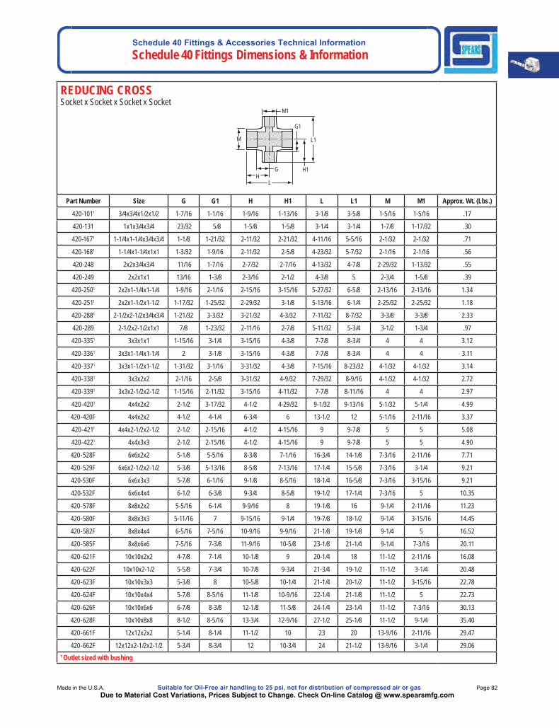
REDUCING CROSSSocket x Socket x Socket x Socket
M L1
L
H1
G1
M1
HG
Part Number Size G G1 H H1 L L1 M M1 Approx. Wt. (Lbs.)
420-1011 3/4x3/4x1/2x1/2 1-7/16 1-1/16 1-9/16 1-13/16 3-1/8 3-5/8 1-5/16 1-5/16 .17
420-131 1x1x3/4x3/4 23/32 5/8 1-5/8 1-5/8 3-1/4 3-1/4 1-7/8 1-17/32 .30
420-1671 1-1/4x1-1/4x3/4x3/4 1-1/8 1-21/32 2-11/32 2-21/32 4-11/16 5-5/16 2-1/32 2-1/32 .71
420-1681 1-1/4x1-1/4x1x1 1-3/32 1-9/16 2-11/32 2-5/8 4-23/32 5-7/32 2-1/16 2-1/16 .56
420-248 2x2x3/4x3/4 11/16 1-7/16 2-7/32 2-7/16 4-13/32 4-7/8 2-29/32 1-13/32 .55
420-249 2x2x1x1 13/16 1-3/8 2-3/16 2-1/2 4-3/8 5 2-3/4 1-5/8 .39
420-2501 2x2x1-1/4x1-1/4 1-9/16 2-1/16 2-15/16 3-15/16 5-27/32 6-5/8 2-13/16 2-13/16 1.34
420-2511 2x2x1-1/2x1-1/2 1-17/32 1-25/32 2-29/32 3-1/8 5-13/16 6-1/4 2-25/32 2-25/32 1.18
420-2881 2-1/2x2-1/2x3/4x3/4 1-21/32 3-3/32 3-21/32 4-3/32 7-11/32 8-7/32 3-3/8 3-3/8 2.33
420-289 2-1/2x2-1/2x1x1 7/8 1-23/32 2-11/16 2-7/8 5-11/32 5-3/4 3-1/2 1-3/4 .97
420-3351 3x3x1x1 1-15/16 3-1/4 3-15/16 4-3/8 7-7/8 8-3/4 4 4 3.12
420-3361 3x3x1-1/4x1-1/4 2 3-1/8 3-15/16 4-3/8 7-7/8 8-3/4 4 4 3.11
420-3371 3x3x1-1/2x1-1/2 1-31/32 3-1/16 3-31/32 4-3/8 7-15/16 8-23/32 4-1/32 4-1/32 3.14
420-3381 3x3x2x2 2-1/16 2-5/8 3-31/32 4-9/32 7-29/32 8-9/16 4-1/32 4-1/32 2.72
420-3391 3x3x2-1/2x2-1/2 1-15/16 2-11/32 3-15/16 4-11/32 7-7/8 8-11/16 4 4 2.97
420-4201 4x4x2x2 2-1/2 3-17/32 4-1/2 4-29/32 9-1/32 9-13/16 5-1/32 5-1/4 4.99
420-420F 4x4x2x2 4-1/2 4-1/4 6-3/4 6 13-1/2 12 5-1/16 2-11/16 3.37
420-4211 4x4x2-1/2x2-1/2 2-1/2 2-15/16 4-1/2 4-15/16 9 9-7/8 5 5 5.08
420-4221 4x4x3x3 2-1/2 2-15/16 4-1/2 4-15/16 9 9-7/8 5 5 4.90
420-528F 6x6x2x2 5-1/8 5-5/16 8-3/8 7-1/16 16-3/4 14-1/8 7-3/16 2-11/16 7.71
420-529F 6x6x2-1/2x2-1/2 5-3/8 5-13/16 8-5/8 7-13/16 17-1/4 15-5/8 7-3/16 3-1/4 9.21
420-530F 6x6x3x3 5-7/8 6-1/16 9-1/8 8-5/16 18-1/4 16-5/8 7-3/16 3-15/16 9.21
420-532F 6x6x4x4 6-1/2 6-3/8 9-3/4 8-5/8 19-1/2 17-1/4 7-3/16 5 10.35
420-578F 8x8x2x2 5-5/16 6-1/4 9-9/16 8 19-1/8 16 9-1/4 2-11/16 11.23
420-580F 8x8x3x3 5-11/16 7 9-15/16 9-1/4 19-7/8 18-1/2 9-1/4 3-15/16 14.45
420-582F 8x8x4x4 6-5/16 7-5/16 10-9/16 9-9/16 21-1/8 19-1/8 9-1/4 5 16.52
420-585F 8x8x6x6 7-5/16 7-3/8 11-9/16 10-5/8 23-1/8 21-1/4 9-1/4 7-3/16 20.11
420-621F 10x10x2x2 4-7/8 7-1/4 10-1/8 9 20-1/4 18 11-1/2 2-11/16 16.08
420-622F 10x10x2-1/2 5-5/8 7-3/4 10-7/8 9-3/4 21-3/4 19-1/2 11-1/2 3-1/4 20.48
420-623F 10x10x3x3 5-3/8 8 10-5/8 10-1/4 21-1/4 20-1/2 11-1/2 3-15/16 22.78
420-624F 10x10x4x4 5-7/8 8-5/16 11-1/8 10-9/16 22-1/4 21-1/8 11-1/2 5 22.73
420-626F 10x10x6x6 6-7/8 8-3/8 12-1/8 11-5/8 24-1/4 23-1/4 11-1/2 7-3/16 30.13
420-628F 10x10x8x8 8-1/2 8-5/16 13-3/4 12-9/16 27-1/2 25-1/8 11-1/2 9-1/4 35.40
420-661F 12x12x2x2 5-1/4 8-1/4 11-1/2 10 23 20 13-9/16 2-11/16 29.47
420-662F 12x12x2-1/2x2-1/2 5-3/4 8-3/4 12 10-3/4 24 21-1/2 13-9/16 3-1/4 29.061 Outlet sized with bushing
Schedule 40 Fittings & Accessories Technical Information Schedule 40 Fittings Dimensions & Information
Page 83 Suitable for Oil-Free air handling to 25 psi, not for distribution of compressed air or gas Spears® Manufacturing CompanyDue to Material Cost Variations, Prices Subject to Change. Check On-line Catalog @ www.spearsmfg.com
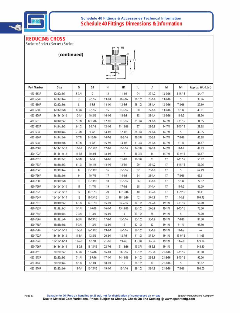
REDUCING CROSSSocket x Socket x Socket x Socket
M L1
L
H1
G1
M1
HG
Part Number Size G G1 H H1 L L1 M M1 Approx. Wt. (Lbs.)
420-663F 12x12x3x3 5-3/4 9 12 11-1/4 24 22-1/2 13-9/16 3-15/16 34.47
420-664F 12x12x4x4 7 9-5/16 13-1/4 11-9/16 26-1/2 23-1/8 13-9/16 5 33.96
420-666F 12x12x6x6 8 9-3/8 14-1/4 12-5/8 28-1/2 25-1/4 13-9/16 7-3/16 39.69
420-668F 12x12x8x8 8-3/4 9-5/16 15 13-9/16 30 27-1/8 13-9/16 9-1/4 45.81
420-670F 12x12x10x10 10-1/4 10-3/8 16-1/2 15-5/8 33 31-1/4 13-9/16 11-1/2 53.90
420-691F 14x14x2x2 5-7/8 8-13/16 12-7/8 10-9/16 25-3/4 21-1/8 14-7/8 2-11/16 34.95
420-693F 14x14x3x3 6-1/2 9-9/16 13-1/2 11-13/16 27 23-5/8 14-7/8 3-15/16 38.68
420-694F 14x14x4x4 7-3/8 9-7/8 14-3/8 12-1/8 28-3/4 24-1/4 14-7/8 5 40.35
420-696F 14x14x6x6 7-7/8 9-15/16 14-7/8 13-3/16 29-3/4 26-3/8 14-7/8 7-3/16 46.98
420-698F 14x14x8x8 8-7/8 9-7/8 15-7/8 14-1/8 31-3/4 28-1/4 14-7/8 9-1/4 44.67
420-700F 14x14x10x10 10-3/8 10-15/16 17-3/8 16-3/16 34-3/4 32-3/8 14-7/8 11-1/2 44.43
420-702F 14x14x12x12 11-3/8 10-3/4 18-3/8 17 36-3/4 34 14-7/8 13-9/16 66.57
420-751F 16x16x2x2 6-3/8 9-3/4 14-3/8 11-1/2 28-3/4 23 17 2-11/16 50.82
420-753F 16x16x3x3 6-1/2 10-1/2 14-1/2 12-3/4 29 25-1/2 17 3-15/16 56.76
420-754F 16x16x4x4 8 10-13/16 16 13-1/16 32 26-1/8 17 5 62.49
420-756F 16x16x6x6 9 10-7/8 17 14-1/8 34 28-1/4 17 7-3/16 66.61
420-758F 16x16x8x8 10 10-13/16 18 15-1/16 36 30-1/8 17 9-1/4 77.97
420-760F 16x16x10x10 11 11-7/8 19 17-1/8 38 34-1/4 17 11-1/2 86.09
420-762F 16x16x12x12 12 11-11/16 20 17-15/16 40 35-7/8 17 13-9/16 91.41
420-764F 16x16x14x14 13 11-15/16 21 18-15/16 42 37-7/8 17 14-7/8 109.43
420-781F 18x18x2x2 6-1/4 10-11/16 15-1/4 12-7/16 30-1/2 24-7/8 19-1/8 2-11/16 66.00
420-783F 18x18x3x3 7-1/4 11-7/16 16-1/4 13-11/16 32-1/2 27-3/8 19-1/8 3-15/16 73.00
420-784F 18x18x4x4 7-3/4 11-3/4 16-3/4 14 33-1/2 28 19-1/8 5 76.00
420-786F 18x18x6x6 8-3/4 11-13/16 17-3/4 15-1/16 35-1/2 30-1/8 19-1/8 7-3/16 84.00
420-788F 18x18x8x8 9-3/4 11-3/4 18-3/4 16 37-1/2 32 19-1/8 9-1/4 93.50
420-790F 18x18x10x10 10-3/4 12-13/16 19-3/4 18-1/16 39-1/2 36-1/8 19-1/8 11-1/2 ---
420-792F 18x18x12x12 11-3/4 12-5/8 20-3/4 18-7/8 41-1/2 37-3/4 19-1/8 13-9/16 111.65
420-794F 18x18x14x14 12-7/8 12-7/8 21-7/8 19-7/8 43-3/4 39-3/4 19-1/8 14-7/8 129.34
420-796F 18x18x16x16 13-7/8 13-13/16 22-7/8 21-13/16 45-3/4 43-5/8 19-1/8 17 145.80
420-811F 20x20x2x2 6-3/4 12-7/16 16-3/4 14-3/16 33-1/2 28-3/8 21-3/16 2-11/16 83.00
420-813F 20x20x3x3 7-1/4 12-7/16 17-1/4 14-11/16 34-1/2 29-3/8 21-3/16 3-15/16 92.00
420-814F 20x20x4x4 8-1/4 12-3/4 18-1/4 15 36-1/2 30 21-3/16 5 95.82
420-816F 20x20x6x6 19-1/4 12-13/16 19-1/4 16-1/16 38-1/2 32-1/8 21-3/16 7-3/16 105.00

Schedule 40 Fittings & Accessories Technical InformationSchedule 40 Fittings Dimensions & Information
Made in the U.S.A. Suitable for Oil-Free air handling to 25 psi, not for distribution of compressed air or gas Page 84Due to Material Cost Variations, Prices Subject to Change. Check On-line Catalog @ www.spearsmfg.com
REDUCING CROSSSocket x Socket x Socket x Socket
M L1
L
H1
G1
M1
HG
Part Number Size G G1 H H1 L L1 M M1 Approx. Wt. (Lbs.)
420-818F 20x20x8x8 10-1/4 12-3/4 20-1/4 17 40-1/2 34 21-3/16 9-1/4 115.00
420-820F 20x20x10x10 11-1/4 13-13/16 21-1/4 19-1/16 42-1/2 38-1/8 21-3/16 11-1/2 126.30
420-822F 20x20x12x12 12-1/4 13-5/8 22-1/4 19-7/8 44-1/2 39-3/4 21-3/16 13-9/16 140.46
420-824F 20x20x14x14 13-1/4 13-7/8 23-1/4 20-7/8 46-1/2 41-3/4 21-3/16 14-7/8 140.77
420-826F 20x20x16x16 14-1/4 14-13/16 24-1/4 22-13/16 48-1/2 45-5/8 21-3/16 17 165.34
420-828F 20x20x18x18 15-1/4 14-3/8 25-1/4 23-3/8 50-1/2 46-3/4 21-3/16 19-1/8 193.92
420-901F 24x24x2x2 8-1/8 14-5/16 20-1/8 16-1/16 40-1/4 32-1/8 25-3/8 2-11/16 156.00
420-903F 24x24x3x3 8-5/8 14-5/6 20-5/8 16-9/16 41-1/4 33-1/8 25-3/8 3-15/16 162.00
420-904F 24x24x4x4 9-1/8 14-5/8 21-1/8 16-7/8 42-1/4 33-3/4 25-3/8 5 167.00
420-906F 24x24x6x6 10-1/8 14-11/16 22-1/8 17-15/16 44-1/4 35-7/8 25-3/8 7-3/16 179.90
420-908F 24x24x8x8 11-1/8 14-5/8 23-1/8 18-7/8 46-1/4 37-3/4 25-3/8 9-1/4 193.00
420-910F 24x24x10x10 12-1/8 15-11/16 24-1/8 20-15/16 48-1/4 41-7/8 25-3/8 11-1/2 190.14
420-912F 24x24x12x12 13-1/8 15-1/2 25-1/8 21-3/4 50-1/4 43-1/2 25-3/8 13-9/16 205.85
420-914F 24x24x14x14 13-3/4 15-3/4 25-3/4 22-3/4 51-1/2 45-1/2 25-3/8 14-7/8 103.61
420-916F 24x24x16x16 14-3/4 16-11/16 26-3/4 24-11/16 53-1/2 49-3/8 25-3/8 17 243.82
420-918F 24x24x18x18 15-3/4 16-1/4 27-3/4 25-1/4 55-1/2 50-1/2 25-3/8 19-1/8 268.14
420-920F 24x24x20x20 16-3/4 17-3/8 28-3/4 27-3/8 57-1/2 54-3/4 25-3/8 21-3/16 292.79
CROSSSocket x Mipt x Socket x Mipt
L1
LH
G
H1
G1M
Part Number Size G G1 H H1 L L1 M Approx. Wt. (Lbs.)
421A-010 1x1x1x1 21/32 1-1/32 1-23/32 1-7/8 3-7/16 3-3/4 1-5/8 .19
Schedule 40 Fittings & Accessories Technical Information Schedule 40 Fittings Dimensions & Information
Page 85 Suitable for Oil-Free air handling to 25 psi, not for distribution of compressed air or gas Spears® Manufacturing CompanyDue to Material Cost Variations, Prices Subject to Change. Check On-line Catalog @ www.spearsmfg.com
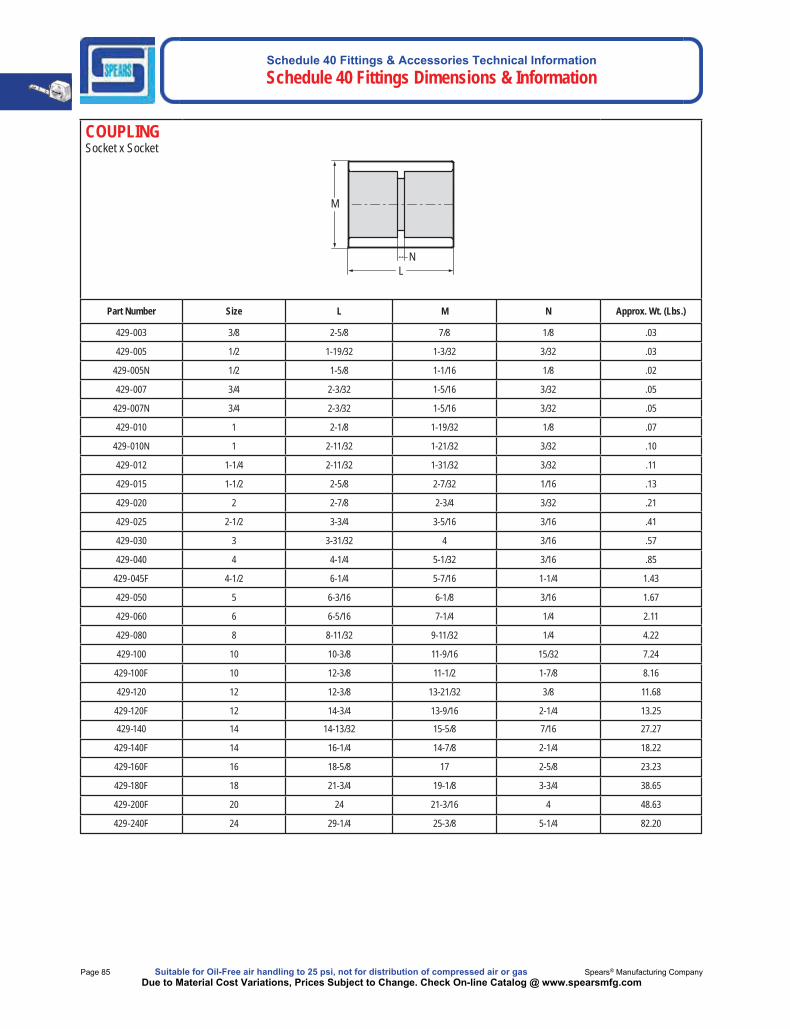
COUPLINGSocket x Socket
M
L N
Part Number Size L M N Approx. Wt. (Lbs.)
429-003 3/8 2-5/8 7/8 1/8 .03
429-005 1/2 1-19/32 1-3/32 3/32 .03
429-005N 1/2 1-5/8 1-1/16 1/8 .02
429-007 3/4 2-3/32 1-5/16 3/32 .05
429-007N 3/4 2-3/32 1-5/16 3/32 .05
429-010 1 2-1/8 1-19/32 1/8 .07
429-010N 1 2-11/32 1-21/32 3/32 .10
429-012 1-1/4 2-11/32 1-31/32 3/32 .11
429-015 1-1/2 2-5/8 2-7/32 1/16 .13
429-020 2 2-7/8 2-3/4 3/32 .21
429-025 2-1/2 3-3/4 3-5/16 3/16 .41
429-030 3 3-31/32 4 3/16 .57
429-040 4 4-1/4 5-1/32 3/16 .85
429-045F 4-1/2 6-1/4 5-7/16 1-1/4 1.43
429-050 5 6-3/16 6-1/8 3/16 1.67
429-060 6 6-5/16 7-1/4 1/4 2.11
429-080 8 8-11/32 9-11/32 1/4 4.22
429-100 10 10-3/8 11-9/16 15/32 7.24
429-100F 10 12-3/8 11-1/2 1-7/8 8.16
429-120 12 12-3/8 13-21/32 3/8 11.68
429-120F 12 14-3/4 13-9/16 2-1/4 13.25
429-140 14 14-13/32 15-5/8 7/16 27.27
429-140F 14 16-1/4 14-7/8 2-1/4 18.22
429-160F 16 18-5/8 17 2-5/8 23.23
429-180F 18 21-3/4 19-1/8 3-3/4 38.65
429-200F 20 24 21-3/16 4 48.63
429-240F 24 29-1/4 25-3/8 5-1/4 82.20

Schedule 40 Fittings & Accessories Technical InformationSchedule 40 Fittings Dimensions & Information
Made in the U.S.A. Suitable for Oil-Free air handling to 25 psi, not for distribution of compressed air or gas Page 86Due to Material Cost Variations, Prices Subject to Change. Check On-line Catalog @ www.spearsmfg.com
DEEP SOCKET COUPLINGSocket x Socket
N
M
L
Part Number Size L M N Approx. Wt. (Lbs.)479-005N 1/2 2-1/2 1-1/16 3/16 .04479-007 3/4 2-7/8 1-5/16 3/32 .07479-010 1 3-5/8 1-5/8 3/32 .13479-015 1-1/2 4-5/8 2-1/4 1/8 .24479-020 2 5-3/32 2-3/4 3/32 .36479-025 2-1/2 7-1/2 3-5/16 1/4 .79479-030 3 8 4 1/4 1.06479-040 4 8-3/16 5 5/16 1.53
479-045F 4-1/2 9-1/2 5-7/16 1-1/2 1.92479-060F 6 12 7-3/16 1-1/2 3.72
REDUCER COUPLINGSocket x Socket
M1 M
N L
Part Number Size L M M1 N Approx. Wt. (Lbs.)429-101 3/4x1/2 1-25/32 1-5/16 1-3/32 1/8 .04429-130 1x1/2 2-7/32 1-5/8 1-3/32 13/32 .07429-131 1x3/4 2-1/8 1-5/8 1-5/16 1/8 .07429-166 1-1/4x1/2 2-9/16 2-3/32 1-5/32 7/16 .13429-167 1-1/4x3/4 2-19/32 2-3/32 1-5/8 11/32 .17429-168 1-1/4x1 2-11/16 2-1/8 1-3/4 5/16 .17429-210 1-1/2x3/4 2-13/16 2-11/32 1-13/32 7/16 .19429-211 1-1/2x1 2-23/32 2-7/32 1-5/8 3/8 .13429-212 1-1/2x1-1/4 2-13/16 2-13/32 2-1/8 5/32 .22429-247 2x1/2 3-3/32 2-7/8 1-5/32 11/16 .30429-248 2x3/4 3-7/32 2-7/8 1-13/32 23/32 .30429-249 2x1 3-1/2 2-13/16 2-5/16 3/4 .41429-250 2x1-1/4 3-1/16 2-23/32 1-31/32 17/32 .20429-251 2x1-1/2 2-13/16 2-27/32 2-1/4 1/8 .19429-291 2-1/2x1-1/2 3-3/4 3-1/2 2-3/8 19/32 .52429-292 2-1/2x2 3-5/8 3-15/32 2-7/8 7/16 .48429-3351 3x1 4-3/16 4-5/32 2-7/8 1-1/4 .91429-3371 3x1-1/2 4-3/16 4-5/32 2-29/32 1 .87
1 Outlet sized with bushing
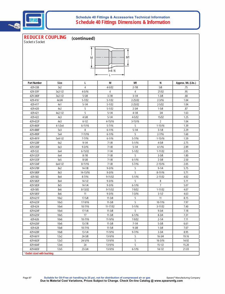
Schedule 40 Fittings & Accessories Technical Information Schedule 40 Fittings Dimensions & Information
Page 87 Suitable for Oil-Free air handling to 25 psi, not for distribution of compressed air or gas Spears® Manufacturing CompanyDue to Material Cost Variations, Prices Subject to Change. Check On-line Catalog @ www.spearsmfg.com
REDUCER COUPLINGSocket x Socket
M1 M
N L
Part Number Size L M M1 N Approx. Wt. (Lbs.)429-338 3x2 4 4-5/32 2-7/8 5/8 .75429-3391 3x2-1/2 4-5/16 4 4 21/32 .95429-340F 3x2-1/2 5-5/8 3-7/8 3-1/4 1-3/8 .68429-4161 4x3/4 5-7/32 5-1/32 2-25/32 2-3/16 1.04429-417 4x1 5-1/4 5-1/32 2-25/32 2-5/32 1.04429-420 4x2 5 5-1/32 2-3/4 1-5/8 .87429-421 4x2-1/2 5 5-1/4 4-1/8 3/4 1.63429-422 4x3 4-5/8 5-1/4 4-5/32 15/32 1.25
429-422F 4x3 6-1/2 4-15/16 3-15/16 2 1.04429-460F 4-1/2x4 6-11/16 5-7/16 5 1-15/16 1.39429-488F 5x3 8 6-1/16 5-1/4 3-1/8 2.29429-490F 5x4 7-11/16 6-1/16 5 2-7/16 1.60429-491F 5x4-1/2 7-7/16 6-1/16 5-7/16 1-15/16 1.59429-528F 6x2 9-1/4 7-1/8 5-1/16 4-5/8 2.75429-530F 6x3 9-3/16 7-1/8 5-1/4 4-1/16 2.89429-532 6x4 6-15/32 7-1/4 5-1/32 1-11/32 2.05
429-532F 6x4 8-7/8 7-1/8 5 3-3/8 1.80429-533F 6x5 8-5/8 7-1/8 6-1/16 2-3/8 2.50429-534F 6x4-1/2 8-11/16 7-1/8 5-7/16 2-15/16 2.05429-578F 8x2 14-7/8 9-3/16 5 9-1/4 5.75429-580F 8x3 14-13/16 9-3/16 5 8-11/16 5.71429-582 8x4 8-7/16 9-11/32 5-1/16 2-11/32 4.02
429-582F 8x4 14-1/2 9-3/16 5 8 5.11429-583F 8x5 14-1/4 9-3/16 6-1/16 7 5.07429-585 8x6 8-13/32 9-11/32 7-9/32 1-11/32 4.07
429-585F 8x6 11 9-3/16 7-3/16 3-1/2 4.63429-621F 10x2 17-5/8 11-3/8 5 11 8.15429-623F 10x3 17-9/16 11-3/8 5 10-7/16 7.97429-624 10x4 10-7/16 11-17/32 5-1/16 3-11/32 7.40
429-624F 10x4 17-1/4 11-3/8 5 9-3/4 7.18429-625F 10x5 17 11-3/8 6-1/16 8-3/4 7.31429-626 10x6 10-7/16 11-9/16 7-9/32 2-1/4 7.11
429-626F 10x6 13-7/8 11-3/8 7-1/4 5-3/8 6.61429-628 10x8 10-7/16 11-5/8 9-3/8 1-3/8 7.07
429-628F 10x8 13-1/4 11-9/16 9-7/16 3-3/4 8.95429-661F 12x2 24-3/8 13-9/16 5 16-3/4 19.16429-663F 12x3 24-5/16 13-9/16 5 16-3/16 14.92429-664F 12x4 24 13-9/16 5 15-1/2 15.20429-665F 12x5 23-3/4 13-9/16 6-1/16 14-1/2 21.03
1 Outlet sized with bushing
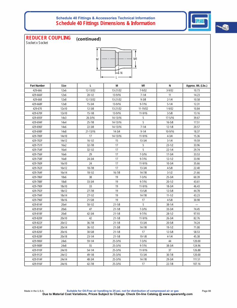
Schedule 40 Fittings & Accessories Technical InformationSchedule 40 Fittings Dimensions & Information
Made in the U.S.A. Suitable for Oil-Free air handling to 25 psi, not for distribution of compressed air or gas Page 88Due to Material Cost Variations, Prices Subject to Change. Check On-line Catalog @ www.spearsmfg.com
REDUCER COUPLINGSocket x Socket
M1 M
N L
Part Number Size L M M1 N Approx. Wt. (Lbs.)429-666 12x6 12-13/32 13-21/32 7-9/32 3-9/32 10.73
429-666F 12x6 20-1/2 13-9/16 7-1/4 11 14.23429-668 12x8 12-13/32 13-21/32 9-3/8 2-1/4 10.58
429-668F 12x8 15-3/4 13-9/16 9-7/16 5-1/4 12.31429-670 12x10 12-3/8 13-21/32 11-19/32 1-9/32 10.84
429-670F 12x10 15-1/8 13-9/16 11-9/16 3-5/8 13.16429-693F 14x3 26-3/16 14-13/16 5 17-5/16 39.67429-694F 14x4 25-7/8 14-13/16 5 16-5/8 17.51429-696F 14x6 22-3/8 14-13/16 7-1/4 12-1/8 20.57429-698F 14x8 21-13/16 14-3/4 9-1/4 10-9/16 18.37429-700F 14x10 17 14-13/16 11-9/16 4-3/4 15.36429-702F 14x12 16-1/2 15 13-3/4 3-1/4 19.59429-751F 16x2 32-7/8 17 5 23-1/2 33.96429-754F 16x4 32-1/2 17 5 22-1/4 29.74429-756F 16x6 29 17 7-3/16 17-3/4 33.53429-758F 16x8 24-3/4 17 9-7/16 12-1/2 33.90429-760F 16x10 24 17 11-9/16 10-3/4 35.66 429-762F 16x12 18-7/8 17 13-3/4 4-5/8 22.40429-764F 16x14 18-1/2 16-7/8 14-7/8 3-1/2 21.66429-786F 18x6 38 19 7-3/16 25-3/4 60.39429-788F 18x8 33-3/4 19 9-7/16 20-1/2 43.61429-790F 18x10 33 19 11-9/16 18-3/4 46.43429-792F 18x12 27-7/8 19 13-5/8 12-5/8 44.78429-794F 18x14 27-1/2 19 14-7/8 11-1/2 43.23429-796F 18x16 21-5/8 19 17 4-5/8 30.98429-814F 20x4 50-1/2 21-1/8 5 38-1/4 ---429-816F 20x6 47 21-1/8 7-3/16 33-3/4 74.45429-818F 20x8 42-3/4 21-1/8 9-7/16 28-1/2 97.93429-820F 20x10 42 21-1/8 11-9/16 26-3/4 82.76429-822F 20x12 36-7/8 21-1/8 13-3/4 20-5/8 74.24429-824F 20x14 36-1/2 21-3/8 14-7/8 19-1/2 71.00429-826F 20x16 30-5/8 21-1/8 17 12-5/8 58.53429-828F 20x18 23-1/4 21-1/8 19-1/8 4-1/4 45.38429-906F 24x6 59-1/4 25-3/16 7-3/16 44 120.00429-908F 24x8 55 25-3/16 9-7/16 38-3/4 124.96429-910F 24x10 54-1/4 25-3/16 11-9/16 37 126.88429-912F 24x12 49-1/8 25-3/16 13-3/4 30-7/8 120.00429-914F 24x14 48-3/4 25-3/16 14-7/8 29-3/4 111.51429-916F 24x16 42-7/8 25-3/16 17 22-7/8 107.16
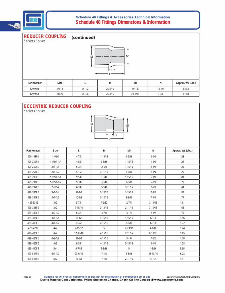
Schedule 40 Fittings & Accessories Technical Information Schedule 40 Fittings Dimensions & Information
Page 89 Suitable for Oil-Free air handling to 25 psi, not for distribution of compressed air or gas Spears® Manufacturing CompanyDue to Material Cost Variations, Prices Subject to Change. Check On-line Catalog @ www.spearsmfg.com
REDUCER COUPLINGSocket x Socket
M1 M
N L
Part Number Size L M M1 N Approx. Wt. (Lbs.)
429-918F 24x18 35-1/2 25-3/16 19-1/8 14-1/2 84.69
429-920F 24x20 28-3/4 25-3/16 21-3/16 6-3/4 61.04
ECCENTRIC REDUCER COUPLING Socket x Socket
M1 M
L N
Part Number Size L M M1 N Approx. Wt. (Lbs.)
429-168FE 1-1/4x1 4-7/8 1-15/16 1-9/16 2-1/8 .28
429-212FE 1-1/2x1-1/4 4-5/8 2-3/16 1-15/16 1-5/8 .24
429-250FE 2x1-1/4 5-3/4 2-5/8 1-15/16 2-1/2 .26
429-251FE 2x1-1/2 5-1/2 2-11/16 2-3/16 2-1/4 .29
429-290FE 2-1/2x1-1/4 9-5/8 3-3/16 1-15/16 6-1/8 .81
429-291FE 2-1/2x1-1/2 9-3/8 3-3/16 2-3/16 5-7/8 .79
429-292FE 2-1/2x2 6-3/8 3-3/16 2-11/16 2-5/8 .44
429-336FE 3x1-1/4 11-1/8 3-13/16 1-15/16 7-3/8 .85
429-337FE 3x1-1/2 10-7/8 3-13/16 2-3/16 7-1/8 .77
429-338E 3x2 5-7/8 4-5/32 2-7/8 2-15/32 1.01
429-338FE 3x2 7-15/16 3-13/16 2-11/16 3-15/16 .63
429-339FE 3x2-1/2 6-3/4 3-7/8 3-1/4 2-1/2 .79
429-418FE 4x1-1/4 16-1/8 4-15/16 1-15/16 12-3/8 1.96
429-419FE 4x1-1/2 15-7/8 4-15/16 2-3/16 12-1/8 1.72
429-420E 4x2 7-15/32 5 2-23/32 4-1/16 1.24
429-420FE 4x2 12-13/16 4-15/16 2-11/16 8-13/16 1.65
429-421FE 4x2-1/2 11-3/4 4-15/16 3-1/4 7-1/2 1.78
429-422FE 4x3 8-5/8 4-15/16 3-15/16 4-1/8 1.28
429-490FE 5x4 9-7/16 6-1/16 5 4-3/16 5.95
429-527FE 6x1-1/2 23-9/16 7-1/8 2-3/16 18-13/16 6.23
429-528FE 6x2 15-7/8 7-1/8 2-11/16 11-1/4 4.41

Schedule 40 Fittings & Accessories Technical InformationSchedule 40 Fittings Dimensions & Information
Made in the U.S.A. Suitable for Oil-Free air handling to 25 psi, not for distribution of compressed air or gas Page 90Due to Material Cost Variations, Prices Subject to Change. Check On-line Catalog @ www.spearsmfg.com
ECCENTRIC REDUCER COUPLING Socket x Socket
M1 M
L N
Part Number Size L M M1 N Approx. Wt. (Lbs.)
429-529FE 6x2-1/2 19-7/16 7-1/8 3-1/4 14-3/16 3.77
429-530FE 6x3 16-5/16 7-1/8 3-15/16 10-13/16 3.92
429-532E 6x4 8-31/32 7-9/32 5-1/32 3-15/16 2.90
429-532FE 6x4 11-1/8 7-1/8 5 5-5/8 2.27
429-533FE 6x5 10-5/8 7-1/8 6-1/16 4-3/8 2.84
429-578FE 8x2 27-1/8 9-3/16 2-11/16 21-1/2 8.22
429-580FE 8x3 25-5/16 9-3/16 3-15/16 18-13/16 7.20
429-582FE 8x4 19-5/8 9-3/16 5 13-3/8 8.22
429-583FE 8x5 15-5/8 9-3/16 6-1/16 12-3/8 6.81429-585FE 8x6 14-3/8 9-3/16 7-3/16 6-7/8 5.53
429-624FE 10x4 22-3/8 11-3/8 5 15-1/8 12.85
429-625FE 10x5 22-3/8 11-3/8 6-1/16 14-1/8 10.65
429-626FE 10x6 17-1/8 11-3/8 7-1/4 8-5/8 7.49
429-628FE 10x8 16-5/16 11-3/8 9-1/4 6-13/16 9.69429-664FE 12x4 32-3/8 13-1/2 5 24-1/8 20.84
429-665FE 12x5 32-3/8 13-1/2 6-1/16 23-1/8 20.37
429-666FE 12x6 27-1/8 13-1/2 7-1/4 17-5/8 16.81
429-668FE 12x8 26-5/16 13-1/2 9-1/4 15-3/16 23.88
429-670FE 12x10 18-3/8 13-1/2 11-1/2 6-7/8 15.07
429-696FE 14x6 31-3/8 15 7-1/4 21-1/8 26.82
429-698FE 14x8 30-9/16 15 9-1/4 19-5/16 26.76429-700FE 14x10 22-3/4 15 11-3/4 10-1/2 23.23
429-702FE 14x12 19 15 13-3/4 5-3/4 25.66
429-756FE 16x6 43-5/8 17 7-1/4 32-3/8 49.49
429-758FE 16x8 42-13/16 17 9-1/4 30-9/16 47.87429-760FE 16x10 34-7/8 17 11-1/2 21-5/8 39.76
429-762FE 16x12 26-1/2 17 13-3/4 12-1/4 34.02
429-764FE 16x14 19 16-7/8 14-7/8 6-3/4 24.61
429-786FE 18x6 56 19 7-1/4 43-3/4 71.11
429-788FE 18x8 55-3/16 19 9-1/4 41-15/16 70.93429-790FE 18x10 47-1/4 19 11-1/2 33 65.32
429-792FE 18x12 38-7/8 19 13-3/4 23-5/8 62.16
429-794FE 18x14 34-1/8 19 14-7/8 18-1/8 54.24
429-796FE 18x16 25 19 17 8 38.72
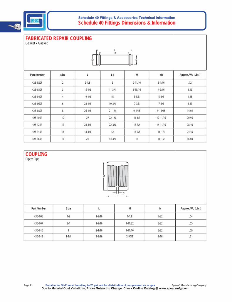
Schedule 40 Fittings & Accessories Technical Information Schedule 40 Fittings Dimensions & Information
Page 91 Suitable for Oil-Free air handling to 25 psi, not for distribution of compressed air or gas Spears® Manufacturing CompanyDue to Material Cost Variations, Prices Subject to Change. Check On-line Catalog @ www.spearsmfg.com
FABRICATED REPAIR COUPLINGGasket x Gasket
L1
M1
L
M
Part Number Size L L1 M M1 Approx. Wt. (Lbs.)
428-020F 2 9-1/8 6 2-11/16 3-1/16 .72
428-030F 3 15-1/2 11-3/4 3-15/16 4-9/16 1.99
428-040F 4 19-1/2 15 5-5/8 5-3/4 4.18
428-060F 6 23-1/2 19-3/4 7-3/8 7-3/4 8.33
428-080F 8 26-1/8 21-1/2 9-1/16 9-13/16 14.01
428-100F 10 27 22-1/8 11-1/2 12-11/16 20.95
428-120F 12 28-3/8 22-3/8 13-3/4 14-11/16 28.49
428-140F 14 18-3/8 12 14-7/8 16-1/4 24.45
428-160F 16 21 14-3/4 17 18-1/2 36.03
COUPLINGFipt x Fipt
M
L N
Part Number Size L M N Approx. Wt. (Lbs.)
430-005 1/2 1-9/16 1-1/8 7/32 .04
430-007 3/4 1-9/16 1-11/32 3/32 .05
430-010 1 2-1/16 1-11/16 3/32 .09
430-012 1-1/4 2-3/16 2-9/32 3/16 .21
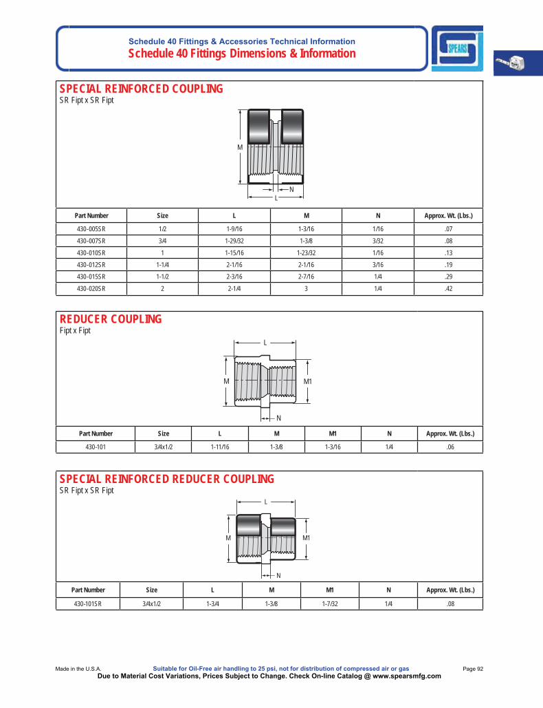
Schedule 40 Fittings & Accessories Technical InformationSchedule 40 Fittings Dimensions & Information
Made in the U.S.A. Suitable for Oil-Free air handling to 25 psi, not for distribution of compressed air or gas Page 92Due to Material Cost Variations, Prices Subject to Change. Check On-line Catalog @ www.spearsmfg.com
SPECIAL REINFORCED COUPLINGSR Fipt x SR Fipt
M
L N
Part Number Size L M N Approx. Wt. (Lbs.)
430-005SR 1/2 1-9/16 1-3/16 1/16 .07
430-007SR 3/4 1-29/32 1-3/8 3/32 .08
430-010SR 1 1-15/16 1-23/32 1/16 .13
430-012SR 1-1/4 2-1/16 2-1/16 3/16 .19
430-015SR 1-1/2 2-3/16 2-7/16 1/4 .29
430-020SR 2 2-1/4 3 1/4 .42
REDUCER COUPLINGFipt x Fipt
M M1
N
L
Part Number Size L M M1 N Approx. Wt. (Lbs.)
430-101 3/4x1/2 1-11/16 1-3/8 1-3/16 1/4 .06
SPECIAL REINFORCED REDUCER COUPLINGSR Fipt x SR Fipt
M M1
N
L
Part Number Size L M M1 N Approx. Wt. (Lbs.)
430-101SR 3/4x1/2 1-3/4 1-3/8 1-7/32 1/4 .08
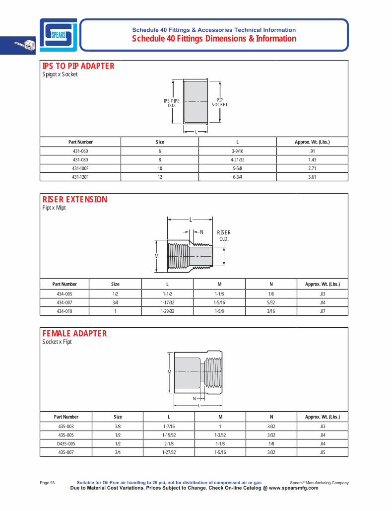
Schedule 40 Fittings & Accessories Technical Information Schedule 40 Fittings Dimensions & Information
Page 93 Suitable for Oil-Free air handling to 25 psi, not for distribution of compressed air or gas Spears® Manufacturing CompanyDue to Material Cost Variations, Prices Subject to Change. Check On-line Catalog @ www.spearsmfg.com
IPS TO PIP ADAPTERSpigot x Socket
PIPSOCKET
IPS PIPE O.D.
L
Part Number Size L Approx. Wt. (Lbs.)
431-060 6 3-9/16 .91
431-080 8 4-21/32 1.43
431-100F 10 5-5/8 2.71
431-120F 12 6-3/4 3.61
RISER EXTENSIONFipt x Mipt
M
N
L
RISERO.D.
Part Number Size L M N Approx. Wt. (Lbs.)
434-005 1/2 1-1/2 1-1/8 1/8 .03
434-007 3/4 1-17/32 1-5/16 5/32 .04
434-010 1 1-29/32 1-5/8 3/16 .07
FEMALE ADAPTERSocket x Fipt
M
LN
Part Number Size L M N Approx. Wt. (Lbs.)
435-003 3/8 1-7/16 1 3/32 .03
435-005 1/2 1-19/32 1-3/32 3/32 .04
D435-005 1/2 2-1/8 1-1/8 1/8 .04
435-007 3/4 1-27/32 1-5/16 3/32 .05
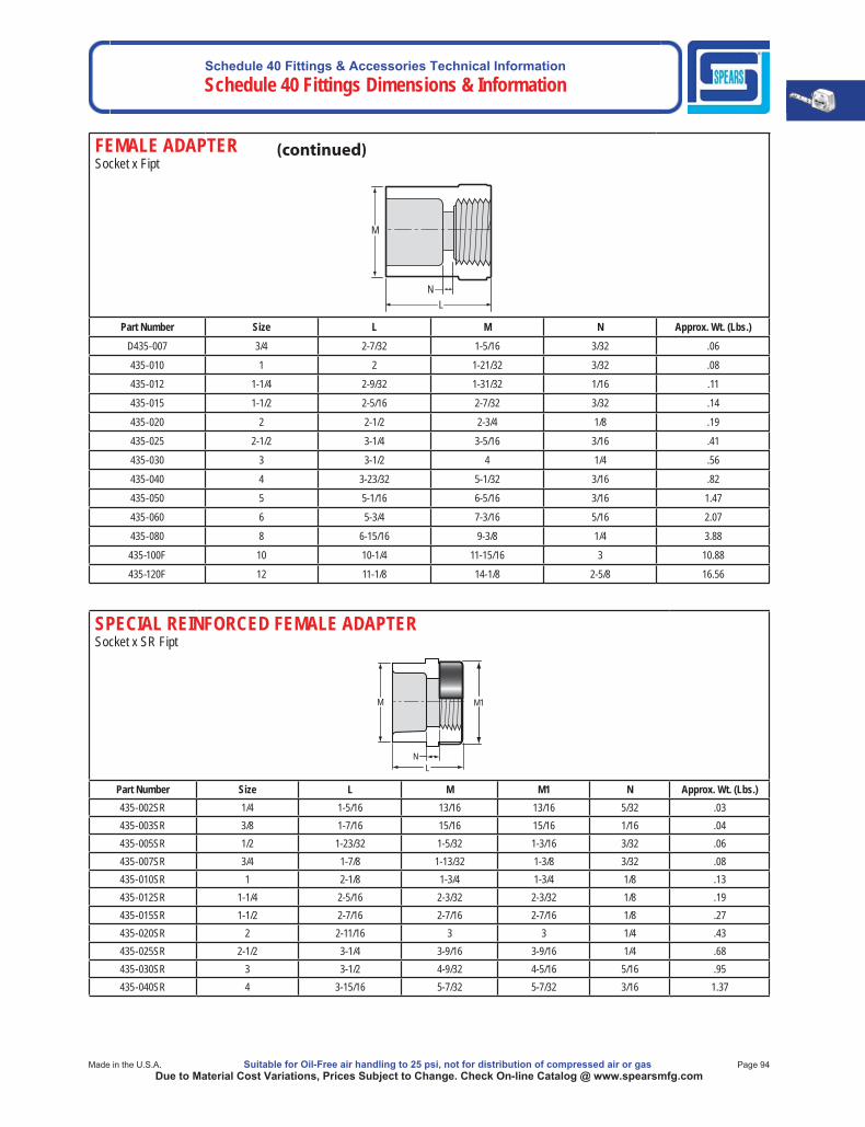
Schedule 40 Fittings & Accessories Technical InformationSchedule 40 Fittings Dimensions & Information
Made in the U.S.A. Suitable for Oil-Free air handling to 25 psi, not for distribution of compressed air or gas Page 94Due to Material Cost Variations, Prices Subject to Change. Check On-line Catalog @ www.spearsmfg.com
FEMALE ADAPTERSocket x Fipt
M
LN
Part Number Size L M N Approx. Wt. (Lbs.)D435-007 3/4 2-7/32 1-5/16 3/32 .06
435-010 1 2 1-21/32 3/32 .08
435-012 1-1/4 2-9/32 1-31/32 1/16 .11
435-015 1-1/2 2-5/16 2-7/32 3/32 .14
435-020 2 2-1/2 2-3/4 1/8 .19
435-025 2-1/2 3-1/4 3-5/16 3/16 .41
435-030 3 3-1/2 4 1/4 .56
435-040 4 3-23/32 5-1/32 3/16 .82
435-050 5 5-1/16 6-5/16 3/16 1.47
435-060 6 5-3/4 7-3/16 5/16 2.07
435-080 8 6-15/16 9-3/8 1/4 3.88
435-100F 10 10-1/4 11-15/16 3 10.88
435-120F 12 11-1/8 14-1/8 2-5/8 16.56
SPECIAL REINFORCED FEMALE ADAPTERSocket x SR Fipt
L
M1
N
M
Part Number Size L M M1 N Approx. Wt. (Lbs.)435-002SR 1/4 1-5/16 13/16 13/16 5/32 .03435-003SR 3/8 1-7/16 15/16 15/16 1/16 .04435-005SR 1/2 1-23/32 1-5/32 1-3/16 3/32 .06435-007SR 3/4 1-7/8 1-13/32 1-3/8 3/32 .08435-010SR 1 2-1/8 1-3/4 1-3/4 1/8 .13435-012SR 1-1/4 2-5/16 2-3/32 2-3/32 1/8 .19435-015SR 1-1/2 2-7/16 2-7/16 2-7/16 1/8 .27435-020SR 2 2-11/16 3 3 1/4 .43435-025SR 2-1/2 3-1/4 3-9/16 3-9/16 1/4 .68435-030SR 3 3-1/2 4-9/32 4-5/16 5/16 .95435-040SR 4 3-15/16 5-7/32 5-7/32 3/16 1.37

Schedule 40 Fittings & Accessories Technical Information Schedule 40 Fittings Dimensions & Information
Page 95 Suitable for Oil-Free air handling to 25 psi, not for distribution of compressed air or gas Spears® Manufacturing CompanyDue to Material Cost Variations, Prices Subject to Change. Check On-line Catalog @ www.spearsmfg.com
REDUCING FEMALE ADAPTERSocket x Fipt
M1M
LN
Part Number Size L M M1 N Approx. Wt. (Lbs.)435-072 1/2x1/4 1-19/32 1-3/32 13/16 1/4 .03435-073 1/2x3/8 1-17/32 1-3/32 15/16 3/16 .03435-074 1/2x3/4 1-19/32 1-3/32 1-5/16 3/16 .05435-098 3/4x1/4 1-15/16 1-13/32 27/32 13/32 .06435-101 3/4x1/2 1-13/16 1-5/16 1-1/8 3/32 .05435-102 3/4x1 1-15/16 1-5/8 1-5/16 3/32 .07435-130 1x1/2 1-27/32 1-5/8 1-1/8 3/32 .07435-131 1x3/4 2-1/8 1-5/8 1-5/16 3/8 .07435-133 1x1-1/2 2-3/8 1-5/8 2-7/32 1/4 .13435-168 1-1/4x1 2-1/2 1-31/32 1-5/8 11/32 .12435-247 2x1/2 2-25/32 2-23/32 1-3/16 21/32 .19
435-460F 4-1/2x4 8-1/4 5-5/8 5 3-7/8 1.92435-578F 8x2 14-7/8 8-5/8 5-1/16 9-5/8 5.75435-582F 8x4 15-3/16 9-1/4 5 9-7/16 5.99435-628F 8x10 11 11-3/4 9-1/4 4-1/16 6.60
SPECIAL REINFORCEDREDUCING FEMALE ADAPTERSocket x SR Fipt
L
M1 M
N
Part Number Size L M M1 N Approx. Wt. (Lbs.)435-072SR 1/2x1/4 1-5/8 1-3/32 27/32 1/4 .04435-073SR 1/2x3/8 1-17/32 1-3/32 31/32 3/16 .04435-074SR 1/2x1/4 1-3/4 1-3/16 1-3/8 1/8 .07435-098SR 3/4x1/4 1-15/16 1-13/32 27/32 13/32 ---435-101SR 3/4x1/2 1-7/8 1-3/8 1-3/16 1/4 .07435-102SR 3/4x1 2-1/16 1-13/32 1-23/32 1/4 .12435-130SR 1x1/2 2 1-11/16 1-3/16 5/32 .10435-131SR 1x3/4 2-1/16 1-3/4 1-3/8 7/32 .12435-247SR 2x1/2 2-13/16 2-23/32 1-3/16 21/32 .20
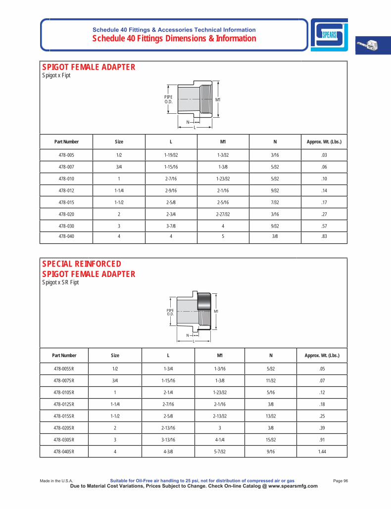
Schedule 40 Fittings & Accessories Technical InformationSchedule 40 Fittings Dimensions & Information
Made in the U.S.A. Suitable for Oil-Free air handling to 25 psi, not for distribution of compressed air or gas Page 96Due to Material Cost Variations, Prices Subject to Change. Check On-line Catalog @ www.spearsmfg.com
SPIGOT FEMALE ADAPTERSpigot x Fipt
M1PIPEO.D.
NL
Part Number Size L M1 N Approx. Wt. (Lbs.)
478-005 1/2 1-19/32 1-3/32 3/16 .03
478-007 3/4 1-15/16 1-3/8 5/32 .06
478-010 1 2-7/16 1-23/32 5/32 .10
478-012 1-1/4 2-9/16 2-1/16 9/32 .14
478-015 1-1/2 2-5/8 2-5/16 7/32 .17
478-020 2 2-3/4 2-27/32 3/16 .27
478-030 3 3-7/8 4 9/32 .57
478-040 4 4 5 3/8 .83
SPECIAL REINFORCEDSPIGOT FEMALE ADAPTERSpigot x SR Fipt
PIPEO.D. M1
LN
Part Number Size L M1 N Approx. Wt. (Lbs.)
478-005SR 1/2 1-3/4 1-3/16 5/32 .05
478-007SR 3/4 1-15/16 1-3/8 11/32 .07
478-010SR 1 2-1/4 1-23/32 5/16 .12
478-012SR 1-1/4 2-7/16 2-1/16 3/8 .18
478-015SR 1-1/2 2-5/8 2-13/32 13/32 .25
478-020SR 2 2-13/16 3 3/8 .39
478-030SR 3 3-13/16 4-1/4 15/32 .91
478-040SR 4 4-3/8 5-7/32 9/16 1.44
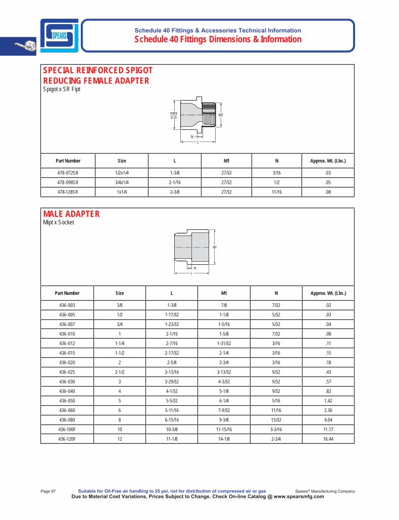
Schedule 40 Fittings & Accessories Technical Information Schedule 40 Fittings Dimensions & Information
Page 97 Suitable for Oil-Free air handling to 25 psi, not for distribution of compressed air or gas Spears® Manufacturing CompanyDue to Material Cost Variations, Prices Subject to Change. Check On-line Catalog @ www.spearsmfg.com
SPECIAL REINFORCED SPIGOTREDUCING FEMALE ADAPTERSpigot x SR Fipt
PIPEO.D. M1
LN
Part Number Size L M1 N Approx. Wt. (Lbs.)
478-072SR 1/2x1/4 1-3/8 27/32 3/16 .03
478-098SR 3/4x1/4 2-1/16 27/32 1/2 .05
478-128SR 1x1/4 2-3/8 27/32 11/16 .08
MALE ADAPTERMipt x Socket
M1
L N
Part Number Size L M1 N Approx. Wt. (Lbs.)
436-003 3/8 1-3/8 7/8 7/32 .02
436-005 1/2 1-17/32 1-1/8 5/32 .03
436-007 3/4 1-23/32 1-5/16 5/32 .04
436-010 1 2-1/16 1-5/8 7/32 .08
436-012 1-1/4 2-7/16 1-31/32 3/16 .11
436-015 1-1/2 2-17/32 2-1/4 3/16 .15
436-020 2 2-5/8 2-3/4 3/16 .18
436-025 2-1/2 3-13/16 3-13/32 9/32 .43
436-030 3 3-29/32 4-3/32 9/32 .57
436-040 4 4-1/32 5-1/8 9/32 .82
436-050 5 5-5/32 6-1/4 5/16 1.42
436-060 6 5-11/16 7-9/32 11/16 2.36
436-080 8 6-15/16 9-3/8 13/32 4.04
436-100F 10 10-3/8 11-15/16 3-3/16 11.17
436-120F 12 11-1/8 14-1/8 2-3/4 16.44
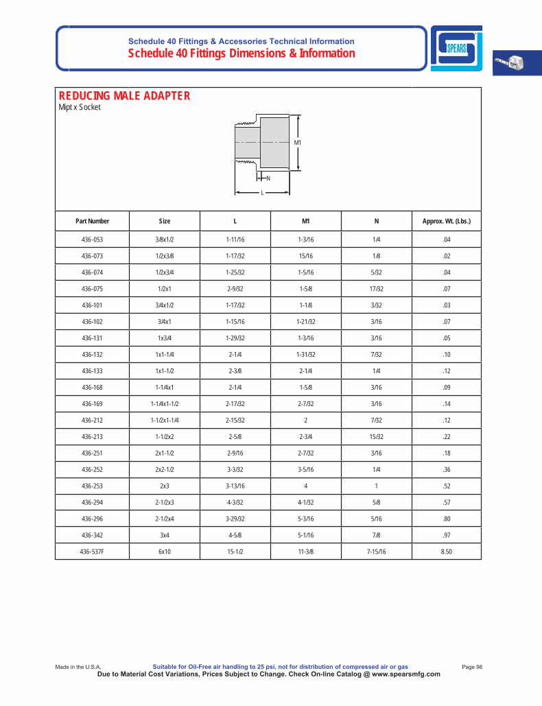
Schedule 40 Fittings & Accessories Technical InformationSchedule 40 Fittings Dimensions & Information
Made in the U.S.A. Suitable for Oil-Free air handling to 25 psi, not for distribution of compressed air or gas Page 98Due to Material Cost Variations, Prices Subject to Change. Check On-line Catalog @ www.spearsmfg.com
REDUCING MALE ADAPTERMipt x Socket
M1
L
N
Part Number Size L M1 N Approx. Wt. (Lbs.)
436-053 3/8x1/2 1-11/16 1-3/16 1/4 .04
436-073 1/2x3/8 1-17/32 15/16 1/8 .02
436-074 1/2x3/4 1-25/32 1-5/16 5/32 .04
436-075 1/2x1 2-9/32 1-5/8 17/32 .07
436-101 3/4x1/2 1-17/32 1-1/8 3/32 .03
436-102 3/4x1 1-15/16 1-21/32 3/16 .07
436-131 1x3/4 1-29/32 1-3/16 3/16 .05
436-132 1x1-1/4 2-1/4 1-31/32 7/32 .10
436-133 1x1-1/2 2-3/8 2-1/4 1/4 .12
436-168 1-1/4x1 2-1/4 1-5/8 3/16 .09
436-169 1-1/4x1-1/2 2-17/32 2-7/32 3/16 .14
436-212 1-1/2x1-1/4 2-15/32 2 7/32 .12
436-213 1-1/2x2 2-5/8 2-3/4 15/32 .22
436-251 2x1-1/2 2-9/16 2-7/32 3/16 .18
436-252 2x2-1/2 3-3/32 3-5/16 1/4 .36
436-253 2x3 3-13/16 4 1 .52
436-294 2-1/2x3 4-3/32 4-1/32 5/8 .57
436-296 2-1/2x4 3-29/32 5-3/16 5/16 .80
436-342 3x4 4-5/8 5-1/16 7/8 .97
436-537F 6x10 15-1/2 11-3/8 7-15/16 8.50
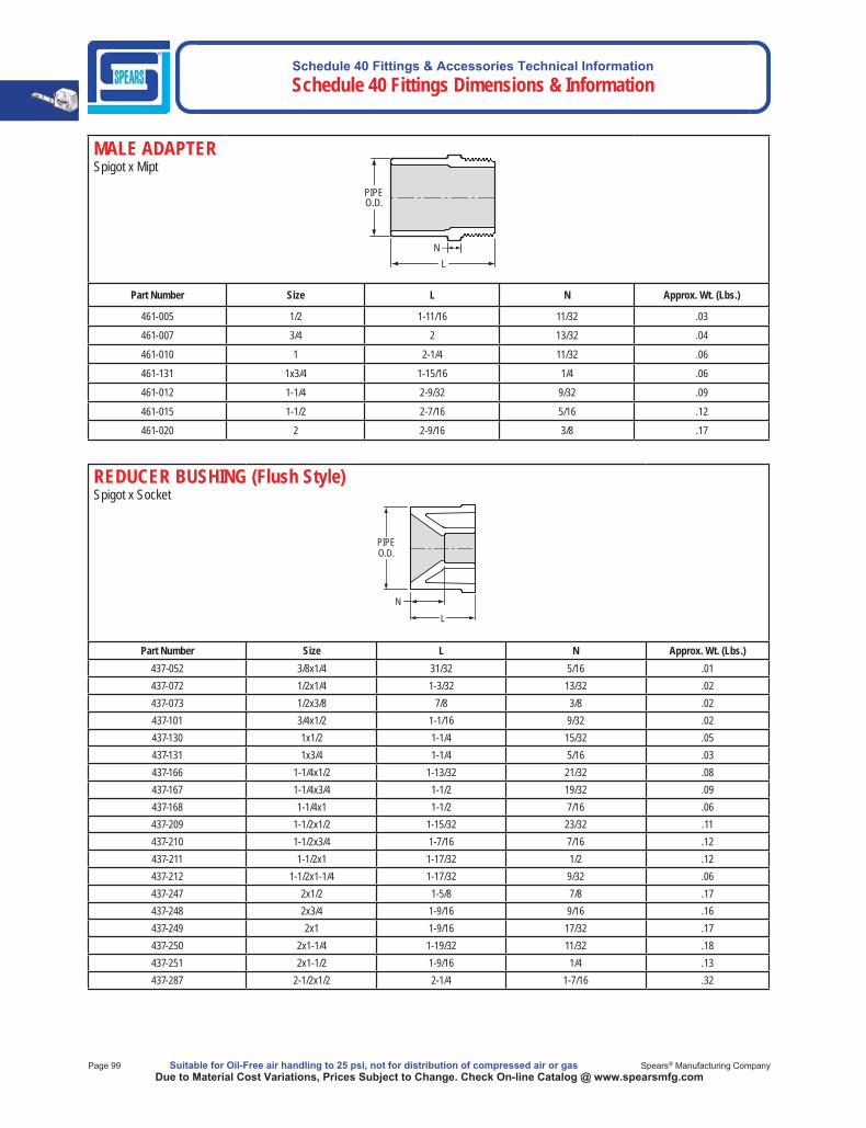
Schedule 40 Fittings & Accessories Technical Information Schedule 40 Fittings Dimensions & Information
Page 99 Suitable for Oil-Free air handling to 25 psi, not for distribution of compressed air or gas Spears® Manufacturing CompanyDue to Material Cost Variations, Prices Subject to Change. Check On-line Catalog @ www.spearsmfg.com
REDUCER BUSHING (Flush Style) Spigot x Socket
L
PIPE O.D.
N
Part Number Size L N Approx. Wt. (Lbs.)437-052 3/8x1/4 31/32 5/16 .01437-072 1/2x1/4 1-3/32 13/32 .02437-073 1/2x3/8 7/8 3/8 .02437-101 3/4x1/2 1-1/16 9/32 .02437-130 1x1/2 1-1/4 15/32 .05437-131 1x3/4 1-1/4 5/16 .03437-166 1-1/4x1/2 1-13/32 21/32 .08437-167 1-1/4x3/4 1-1/2 19/32 .09437-168 1-1/4x1 1-1/2 7/16 .06437-209 1-1/2x1/2 1-15/32 23/32 .11437-210 1-1/2x3/4 1-7/16 7/16 .12437-211 1-1/2x1 1-17/32 1/2 .12437-212 1-1/2x1-1/4 1-17/32 9/32 .06437-247 2x1/2 1-5/8 7/8 .17437-248 2x3/4 1-9/16 9/16 .16437-249 2x1 1-9/16 17/32 .17437-250 2x1-1/4 1-19/32 11/32 .18437-251 2x1-1/2 1-9/16 1/4 .13437-287 2-1/2x1/2 2-1/4 1-7/16 .32
MALE ADAPTERSpigot x Mipt
Part Number Size L N Approx. Wt. (Lbs.)
461-005 1/2 1-11/16 11/32 .03
461-007 3/4 2 13/32 .04
461-010 1 2-1/4 11/32 .06
461-131 1x3/4 1-15/16 1/4 .06
461-012 1-1/4 2-9/32 9/32 .09
461-015 1-1/2 2-7/16 5/16 .12
461-020 2 2-9/16 3/8 .17
PIPE O.D.
N L
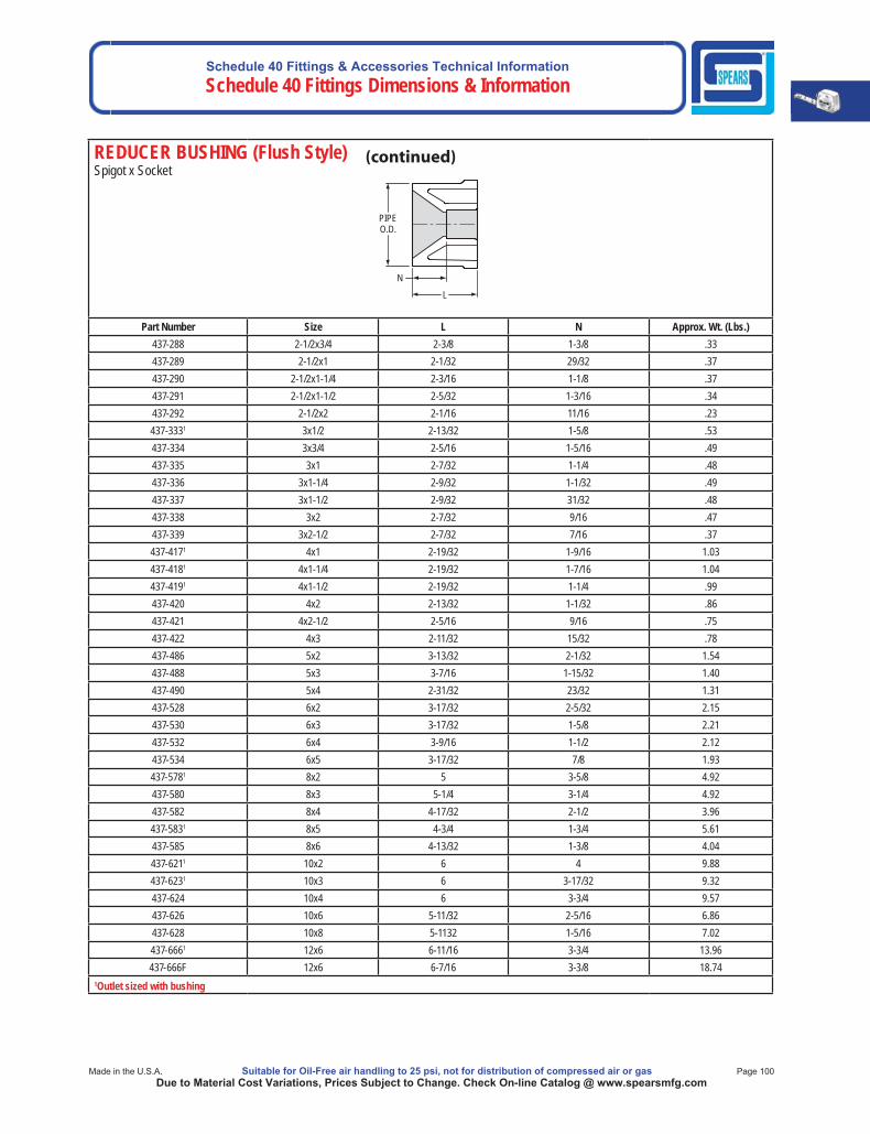
Schedule 40 Fittings & Accessories Technical InformationSchedule 40 Fittings Dimensions & Information
Made in the U.S.A. Suitable for Oil-Free air handling to 25 psi, not for distribution of compressed air or gas Page 100Due to Material Cost Variations, Prices Subject to Change. Check On-line Catalog @ www.spearsmfg.com
REDUCER BUSHING (Flush Style) Spigot x Socket
L
PIPE O.D.
N
Part Number Size L N Approx. Wt. (Lbs.)437-288 2-1/2x3/4 2-3/8 1-3/8 .33437-289 2-1/2x1 2-1/32 29/32 .37437-290 2-1/2x1-1/4 2-3/16 1-1/8 .37437-291 2-1/2x1-1/2 2-5/32 1-3/16 .34437-292 2-1/2x2 2-1/16 11/16 .23437-3331 3x1/2 2-13/32 1-5/8 .53437-334 3x3/4 2-5/16 1-5/16 .49437-335 3x1 2-7/32 1-1/4 .48437-336 3x1-1/4 2-9/32 1-1/32 .49437-337 3x1-1/2 2-9/32 31/32 .48437-338 3x2 2-7/32 9/16 .47437-339 3x2-1/2 2-7/32 7/16 .37437-4171 4x1 2-19/32 1-9/16 1.03437-4181 4x1-1/4 2-19/32 1-7/16 1.04437-4191 4x1-1/2 2-19/32 1-1/4 .99437-420 4x2 2-13/32 1-1/32 .86437-421 4x2-1/2 2-5/16 9/16 .75437-422 4x3 2-11/32 15/32 .78437-486 5x2 3-13/32 2-1/32 1.54437-488 5x3 3-7/16 1-15/32 1.40437-490 5x4 2-31/32 23/32 1.31437-528 6x2 3-17/32 2-5/32 2.15437-530 6x3 3-17/32 1-5/8 2.21437-532 6x4 3-9/16 1-1/2 2.12437-534 6x5 3-17/32 7/8 1.93437-5781 8x2 5 3-5/8 4.92437-580 8x3 5-1/4 3-1/4 4.92437-582 8x4 4-17/32 2-1/2 3.96437-5831 8x5 4-3/4 1-3/4 5.61437-585 8x6 4-13/32 1-3/8 4.04437-6211 10x2 6 4 9.88437-6231 10x3 6 3-17/32 9.32437-624 10x4 6 3-3/4 9.57437-626 10x6 5-11/32 2-5/16 6.86437-628 10x8 5-1132 1-5/16 7.02 437-6661 12x6 6-11/16 3-3/4 13.96437-666F 12x6 6-7/16 3-3/8 18.74
1Outlet sized with bushing
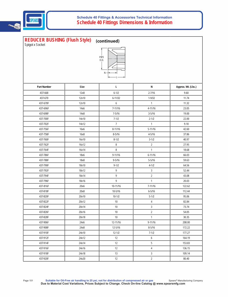
Schedule 40 Fittings & Accessories Technical Information Schedule 40 Fittings Dimensions & Information
Page 101 Suitable for Oil-Free air handling to 25 psi, not for distribution of compressed air or gas Spears® Manufacturing CompanyDue to Material Cost Variations, Prices Subject to Change. Check On-line Catalog @ www.spearsmfg.com
REDUCER BUSHING (Flush Style) Spigot x Socket
L
PIPE O.D.
N
Part Number Size L N Approx. Wt. (Lbs.)
437-668 12x8 6-1/2 2-7/16 9.60
437-670 12x10 6-11/32 1-9/32 11.74
437-670F 12x10 6 1 11.32
437-696F 14x6 7-11/16 4-11/16 23.05
437-698F 14x8 7-5/16 3-5/16 19.00
437-700F 14x10 7-1/2 2-1/2 22.00
437-702F 14x12 7 1 9.18
437-756F 16x6 8-11/16 5-11/16 42.60
437-758F 16x8 8-5/16 4-5/16 37.86
437-760F 16x10 8-1/2 3-1/2 40.97
437-762F 16x12 8 2 27.95
437-764F 16x14 8 1 18.68
437-786F 18x6 9-11/16 6-11/16 66.03
437-788F 18x8 9-5/16 5-5/16 59.63
437-790F 18x10 9-1/2 4-1/2 64.56
437-792F 18x12 9 3 52.44
437-794F 18x14 9 2 43.08
437-796F 18x16 9 1 20.03
437-816F 20x6 10-11/16 7-11/16 122.62
437-818F 20x8 10-5/16 6-5/16 112.44
437-820F 20x10 10-1/2 5-1/2 95.06
437-822F 20x12 10 4 82.84
437-824F 20x14 10 3 73.74
437-826F 20x16 10 2 54.05
437-828F 20x18 10 1 30.35
437-906F 24x6 12-11/16 9-11/16 208.00
437-908F 24x8 12-5/16 8-5/16 172.22
437-910F 24x10 12-1/2 7-1/2 177.27
437-912F 24x12 12 6 164.19
437-914F 24x14 12 5 153.83
437-916F 24x16 12 4 136.15
437-918F 24x18 13 3 109.14
437-920F 24x20 12 2 80.40
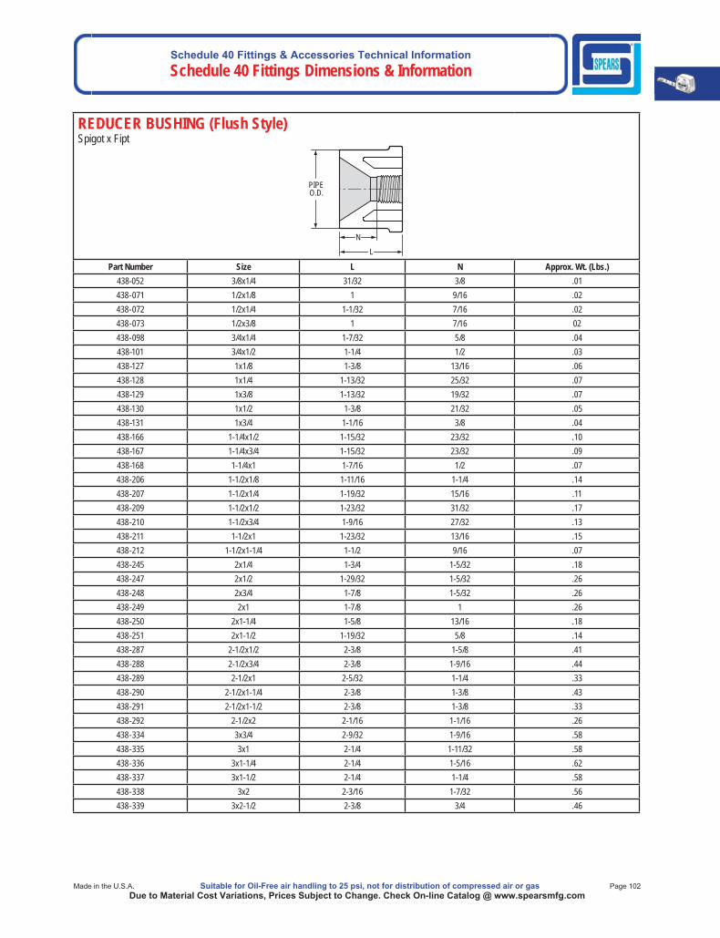
Schedule 40 Fittings & Accessories Technical InformationSchedule 40 Fittings Dimensions & Information
Made in the U.S.A. Suitable for Oil-Free air handling to 25 psi, not for distribution of compressed air or gas Page 102Due to Material Cost Variations, Prices Subject to Change. Check On-line Catalog @ www.spearsmfg.com
REDUCER BUSHING (Flush Style)Spigot x Fipt
PIPE O.D.
L
N
Part Number Size L N Approx. Wt. (Lbs.)438-052 3/8x1/4 31/32 3/8 .01438-071 1/2x1/8 1 9/16 .02438-072 1/2x1/4 1-1/32 7/16 .02438-073 1/2x3/8 1 7/16 02438-098 3/4x1/4 1-7/32 5/8 .04438-101 3/4x1/2 1-1/4 1/2 .03438-127 1x1/8 1-3/8 13/16 .06438-128 1x1/4 1-13/32 25/32 .07438-129 1x3/8 1-13/32 19/32 .07438-130 1x1/2 1-3/8 21/32 .05438-131 1x3/4 1-1/16 3/8 .04438-166 1-1/4x1/2 1-15/32 23/32 .10438-167 1-1/4x3/4 1-15/32 23/32 .09438-168 1-1/4x1 1-7/16 1/2 .07438-206 1-1/2x1/8 1-11/16 1-1/4 .14438-207 1-1/2x1/4 1-19/32 15/16 .11438-209 1-1/2x1/2 1-23/32 31/32 .17438-210 1-1/2x3/4 1-9/16 27/32 .13438-211 1-1/2x1 1-23/32 13/16 .15438-212 1-1/2x1-1/4 1-1/2 9/16 .07438-245 2x1/4 1-3/4 1-5/32 .18438-247 2x1/2 1-29/32 1-5/32 .26438-248 2x3/4 1-7/8 1-5/32 .26438-249 2x1 1-7/8 1 .26438-250 2x1-1/4 1-5/8 13/16 .18438-251 2x1-1/2 1-19/32 5/8 .14438-287 2-1/2x1/2 2-3/8 1-5/8 .41438-288 2-1/2x3/4 2-3/8 1-9/16 .44438-289 2-1/2x1 2-5/32 1-1/4 .33438-290 2-1/2x1-1/4 2-3/8 1-3/8 .43438-291 2-1/2x1-1/2 2-3/8 1-3/8 .33438-292 2-1/2x2 2-1/16 1-1/16 .26438-334 3x3/4 2-9/32 1-9/16 .58438-335 3x1 2-1/4 1-11/32 .58438-336 3x1-1/4 2-1/4 1-5/16 .62438-337 3x1-1/2 2-1/4 1-1/4 .58438-338 3x2 2-3/16 1-7/32 .56438-339 3x2-1/2 2-3/8 3/4 .46
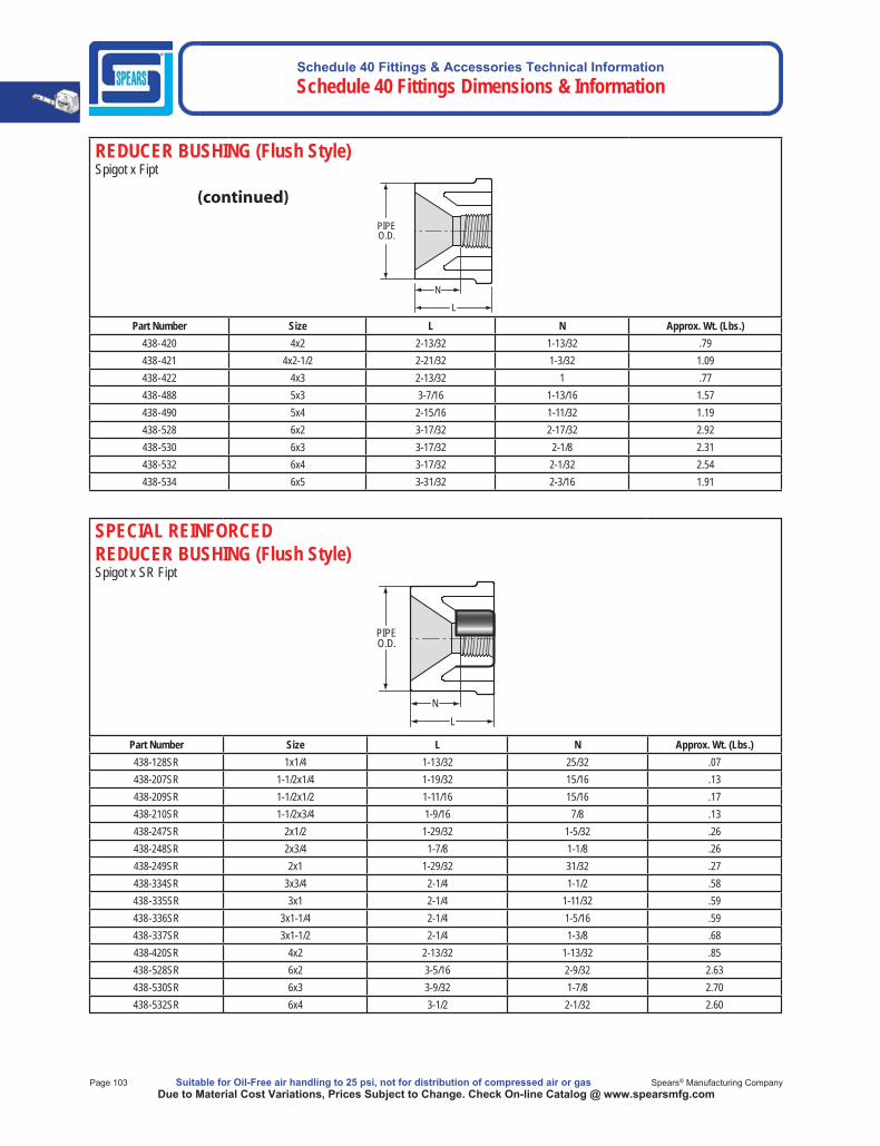
Schedule 40 Fittings & Accessories Technical Information Schedule 40 Fittings Dimensions & Information
Page 103 Suitable for Oil-Free air handling to 25 psi, not for distribution of compressed air or gas Spears® Manufacturing CompanyDue to Material Cost Variations, Prices Subject to Change. Check On-line Catalog @ www.spearsmfg.com
SPECIAL REINFORCEDREDUCER BUSHING (Flush Style)Spigot x SR Fipt
PIPEO.D.
LN
Part Number Size L N Approx. Wt. (Lbs.)438-128SR 1x1/4 1-13/32 25/32 .07438-207SR 1-1/2x1/4 1-19/32 15/16 .13438-209SR 1-1/2x1/2 1-11/16 15/16 .17438-210SR 1-1/2x3/4 1-9/16 7/8 .13438-247SR 2x1/2 1-29/32 1-5/32 .26438-248SR 2x3/4 1-7/8 1-1/8 .26438-249SR 2x1 1-29/32 31/32 .27438-334SR 3x3/4 2-1/4 1-1/2 .58438-335SR 3x1 2-1/4 1-11/32 .59438-336SR 3x1-1/4 2-1/4 1-5/16 .59438-337SR 3x1-1/2 2-1/4 1-3/8 .68438-420SR 4x2 2-13/32 1-13/32 .85438-528SR 6x2 3-5/16 2-9/32 2.63438-530SR 6x3 3-9/32 1-7/8 2.70438-532SR 6x4 3-1/2 2-1/32 2.60
REDUCER BUSHING (Flush Style)Spigot x Fipt
PIPE O.D.
L
N
Part Number Size L N Approx. Wt. (Lbs.)438-420 4x2 2-13/32 1-13/32 .79438-421 4x2-1/2 2-21/32 1-3/32 1.09438-422 4x3 2-13/32 1 .77438-488 5x3 3-7/16 1-13/16 1.57438-490 5x4 2-15/16 1-11/32 1.19438-528 6x2 3-17/32 2-17/32 2.92438-530 6x3 3-17/32 2-1/8 2.31438-532 6x4 3-17/32 2-1/32 2.54438-534 6x5 3-31/32 2-3/16 1.91
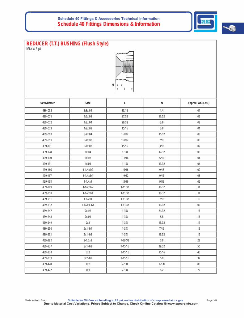
Schedule 40 Fittings & Accessories Technical InformationSchedule 40 Fittings Dimensions & Information
Made in the U.S.A. Suitable for Oil-Free air handling to 25 psi, not for distribution of compressed air or gas Page 104Due to Material Cost Variations, Prices Subject to Change. Check On-line Catalog @ www.spearsmfg.com
REDUCER (T.T.) BUSHING (Flush Style)Mipt x Fipt
L N
Part Number Size L N Approx. Wt. (Lbs.)
439-052 3/8x1/4 13/16 1/4 .01
439-071 1/2x1/8 27/32 13/32 .02
439-072 1/2x1/4 29/32 3/8 .02
439-073 1/2x3/8 15/16 3/8 .01
439-098 3/4x1/4 1-1/32 15/32 .03
439-099 3/4x3/8 1-1/32 7/16 .03
439-101 3/4x1/2 15/16 3/16 .02
439-128 1x1/4 1-1/8 17/32 .05
439-130 1x1/2 1-1/16 5/16 .04
439-131 1x3/4 1-1/8 13/32 .04
439-166 1-1/4x1/2 1-5/16 9/16 .09
439-167 1-1/4x3/4 1-9/32 9/16 .08
439-168 1-1/4x1 1-3/16 9/32 .06
439-209 1-1/2x1/2 1-11/32 19/32 .11
439-210 1-1/2x3/4 1-11/32 19/32 .11
439-211 1-1/2x1 1-11/32 7/16 .10
439-212 1-1/2x1-1/4 1-11/32 13/32 .06
439-247 2x1/2 1-3/8 21/32 .16
439-248 2x3/4 1-3/8 5/8 .16
439-249 2x1 1-3/8 15/32 .17
439-250 2x1-1/4 1-3/8 7/16 .16
439-251 2x1-1/2 1-3/8 13/32 .12
439-292 2-1/2x2 1-29/32 7/8 .22
439-337 3x1-1/2 1-15/16 29/32 .50
439-338 3x2 1-15/16 15/16 .45
439-339 3x2-1/2 1-15/16 5/8 .37
439-420 4x2 2-1/8 1-1/8 .83
439-422 4x3 2-1/8 1/2 .72
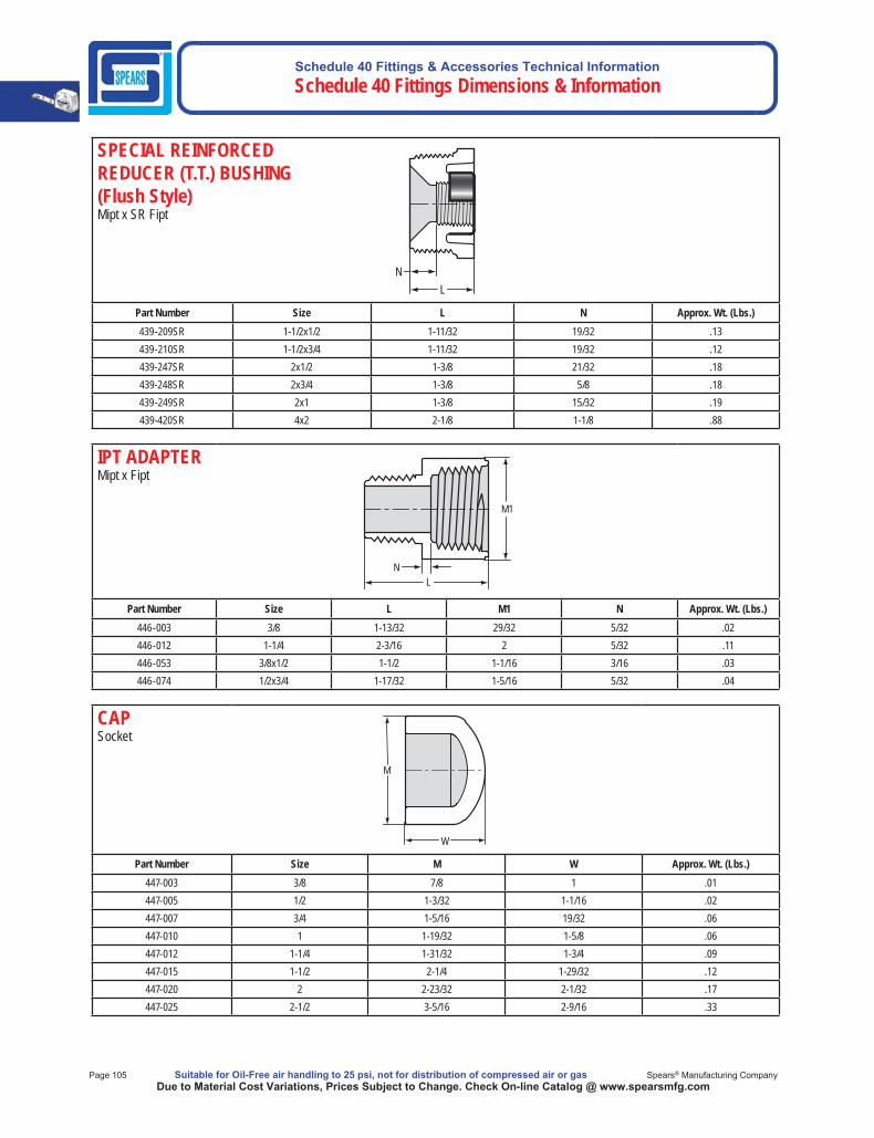
Schedule 40 Fittings & Accessories Technical Information Schedule 40 Fittings Dimensions & Information
Page 105 Suitable for Oil-Free air handling to 25 psi, not for distribution of compressed air or gas Spears® Manufacturing CompanyDue to Material Cost Variations, Prices Subject to Change. Check On-line Catalog @ www.spearsmfg.com
SPECIAL REINFORCEDREDUCER (T.T.) BUSHING (Flush Style)Mipt x SR Fipt
Part Number Size L N Approx. Wt. (Lbs.)439-209SR 1-1/2x1/2 1-11/32 19/32 .13439-210SR 1-1/2x3/4 1-11/32 19/32 .12439-247SR 2x1/2 1-3/8 21/32 .18439-248SR 2x3/4 1-3/8 5/8 .18439-249SR 2x1 1-3/8 15/32 .19439-420SR 4x2 2-1/8 1-1/8 .88
L N
IPT ADAPTERMipt x Fipt
Part Number Size L M1 N Approx. Wt. (Lbs.)446-003 3/8 1-13/32 29/32 5/32 .02446-012 1-1/4 2-3/16 2 5/32 .11446-053 3/8x1/2 1-1/2 1-1/16 3/16 .03446-074 1/2x3/4 1-17/32 1-5/16 5/32 .04
M1
LN
CAPSocket
Part Number Size M W Approx. Wt. (Lbs.)447-003 3/8 7/8 1 .01447-005 1/2 1-3/32 1-1/16 .02447-007 3/4 1-5/16 19/32 .06447-010 1 1-19/32 1-5/8 .06447-012 1-1/4 1-31/32 1-3/4 .09447-015 1-1/2 2-1/4 1-29/32 .12447-020 2 2-23/32 2-1/32 .17447-025 2-1/2 3-5/16 2-9/16 .33
W
M
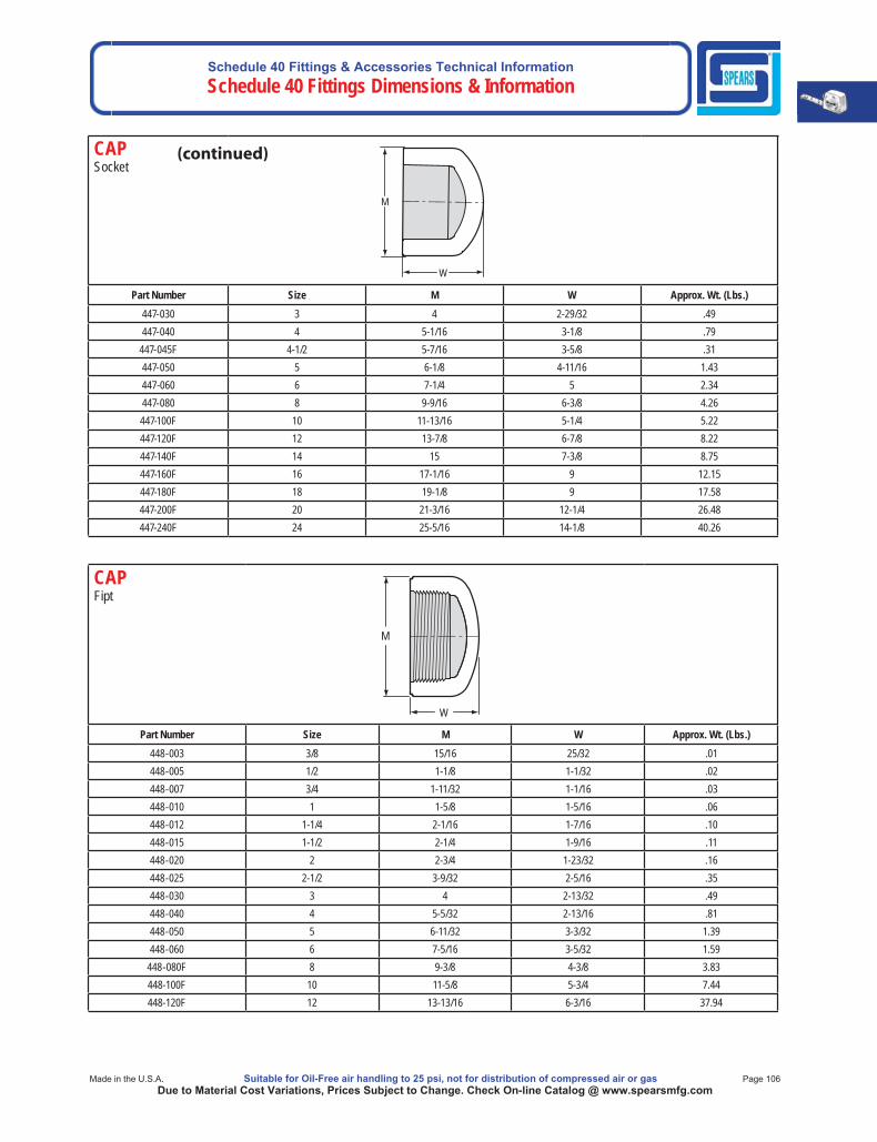
Schedule 40 Fittings & Accessories Technical InformationSchedule 40 Fittings Dimensions & Information
Made in the U.S.A. Suitable for Oil-Free air handling to 25 psi, not for distribution of compressed air or gas Page 106Due to Material Cost Variations, Prices Subject to Change. Check On-line Catalog @ www.spearsmfg.com
CAPSocket
Part Number Size M W Approx. Wt. (Lbs.)447-030 3 4 2-29/32 .49447-040 4 5-1/16 3-1/8 .79447-045F 4-1/2 5-7/16 3-5/8 .31447-050 5 6-1/8 4-11/16 1.43447-060 6 7-1/4 5 2.34447-080 8 9-9/16 6-3/8 4.26447-100F 10 11-13/16 5-1/4 5.22447-120F 12 13-7/8 6-7/8 8.22447-140F 14 15 7-3/8 8.75447-160F 16 17-1/16 9 12.15447-180F 18 19-1/8 9 17.58447-200F 20 21-3/16 12-1/4 26.48447-240F 24 25-5/16 14-1/8 40.26
W
M
CAPFipt
Part Number Size M W Approx. Wt. (Lbs.)448-003 3/8 15/16 25/32 .01448-005 1/2 1-1/8 1-1/32 .02448-007 3/4 1-11/32 1-1/16 .03448-010 1 1-5/8 1-5/16 .06448-012 1-1/4 2-1/16 1-7/16 .10448-015 1-1/2 2-1/4 1-9/16 .11448-020 2 2-3/4 1-23/32 .16448-025 2-1/2 3-9/32 2-5/16 .35448-030 3 4 2-13/32 .49448-040 4 5-5/32 2-13/16 .81448-050 5 6-11/32 3-3/32 1.39448-060 6 7-5/16 3-5/32 1.59448-080F 8 9-3/8 4-3/8 3.83448-100F 10 11-5/8 5-3/4 7.44448-120F 12 13-13/16 6-3/16 37.94
M
W
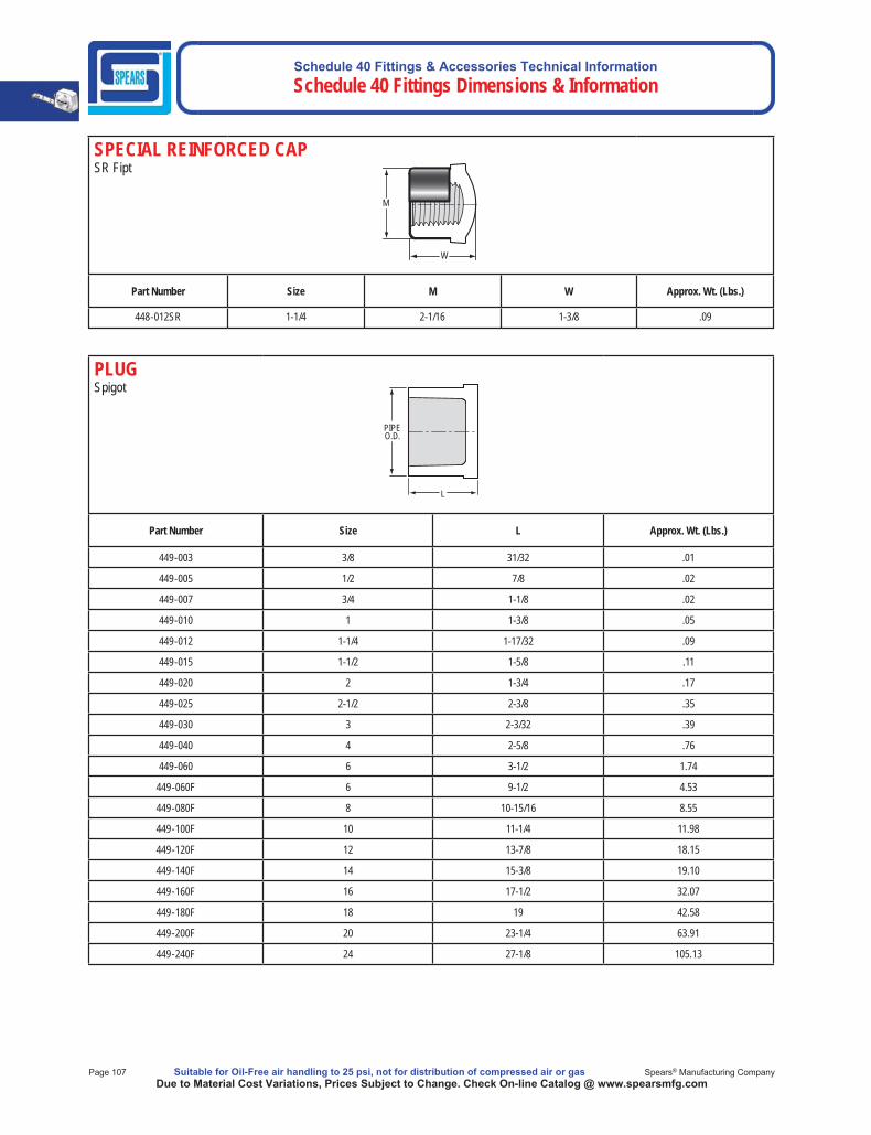
Schedule 40 Fittings & Accessories Technical Information Schedule 40 Fittings Dimensions & Information
Page 107 Suitable for Oil-Free air handling to 25 psi, not for distribution of compressed air or gas Spears® Manufacturing CompanyDue to Material Cost Variations, Prices Subject to Change. Check On-line Catalog @ www.spearsmfg.com
SPECIAL REINFORCED CAPSR Fipt
Part Number Size M W Approx. Wt. (Lbs.)
448-012SR 1-1/4 2-1/16 1-3/8 .09
M
W
PLUG Spigot
Part Number Size L Approx. Wt. (Lbs.)
449-003 3/8 31/32 .01
449-005 1/2 7/8 .02
449-007 3/4 1-1/8 .02
449-010 1 1-3/8 .05
449-012 1-1/4 1-17/32 .09
449-015 1-1/2 1-5/8 .11
449-020 2 1-3/4 .17
449-025 2-1/2 2-3/8 .35
449-030 3 2-3/32 .39
449-040 4 2-5/8 .76
449-060 6 3-1/2 1.74
449-060F 6 9-1/2 4.53
449-080F 8 10-15/16 8.55
449-100F 10 11-1/4 11.98
449-120F 12 13-7/8 18.15
449-140F 14 15-3/8 19.10
449-160F 16 17-1/2 32.07
449-180F 18 19 42.58
449-200F 20 23-1/4 63.91
449-240F 24 27-1/8 105.13
PIPE O.D.
L
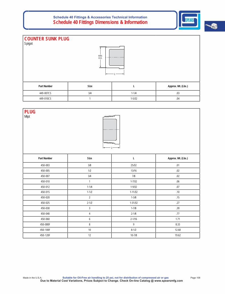
Schedule 40 Fittings & Accessories Technical InformationSchedule 40 Fittings Dimensions & Information
Made in the U.S.A. Suitable for Oil-Free air handling to 25 psi, not for distribution of compressed air or gas Page 108Due to Material Cost Variations, Prices Subject to Change. Check On-line Catalog @ www.spearsmfg.com
COUNTER SUNK PLUGSpigot
PIPEO.D.
L
Part Number Size L Approx. Wt. (Lbs.)
449-007CS 3/4 1-1/4 .03
449-010CS 1 1-5/32 .04
PLUGMipt
Part Number Size L Approx. Wt. (Lbs.)
450-003 3/8 25/32 .01
450-005 1/2 13/16 .02
450-007 3/4 7/8 .02
450-010 1 1-7/32 .06
450-012 1-1/4 1-9/32 .07
450-015 1-1/2 1-11/32 .10
450-020 2 1-3/8 .15
450-025 2-1/2 1-31/32 .27
450-030 3 1-7/8 .39
450-040 4 2-1/8 .77
450-060 6 2-1/16 1.71
450-080F 8 9 8.33
450-100F 10 8-1/2 12.68
450-120F 12 10-7/8 19.62
L

Schedule 40 Fittings & Accessories Technical Information Schedule 40 Fittings Dimensions & Information
Page 109 Suitable for Oil-Free air handling to 25 psi, not for distribution of compressed air or gas Spears® Manufacturing CompanyDue to Material Cost Variations, Prices Subject to Change. Check On-line Catalog @ www.spearsmfg.com
INSERT ADAPTER (PVC White) Insert x I.P.S. Spigot AdapterASTM D 2609
Part Number Size L N Approx. Wt. (Lbs.)460-005 1/2 2-7/16 7/32 .03460-007 3/4 2-23/32 7/32 .04460-010 1 2-9/16 1/16 .07460-012 1-1/4 3-1/32 1/4 .11460-015 1-1/2 3-5/16 5/16 .12460-020 2 3-1/2 3/8 .19460-030 3 4-17/32 13/32 .57460-040 4 5-11/32 5/16 .73
NL
IPSPIPEO.D.
INSERT ADAPTER (PVC White)Insert x I.P.S. Spigot
Part Number Size L N Approx. Wt. (Lbs.)1432-060 6 7-27/32 1 1.691432-080* 8 9-7/8 5/8 5.23
*Fabricated
PIPEO.D.
L
N
INSERT ADAPTER Insert x SocketASTM D 2609
Part Number Size L M1 N Approx. Wt. (Lbs.)474-005 1/2 2-3/8 1-1/16 1/8 .03474-007 3/4 2-7/16 1-5/16 5/32 .05474-010 1 2-5/8 1-5/8 1/8 .07474-012 1-1/4 2-11/16 2 3/16 .10474-015 1-1/2 3-1/16 2-1/4 3/16 .14474-020 2 3 2-11/16 3/16 .17474-030 3 4-3/4 4 5/16 .51474-040 4 5-5/8 5 3/8 .81
NL
M1
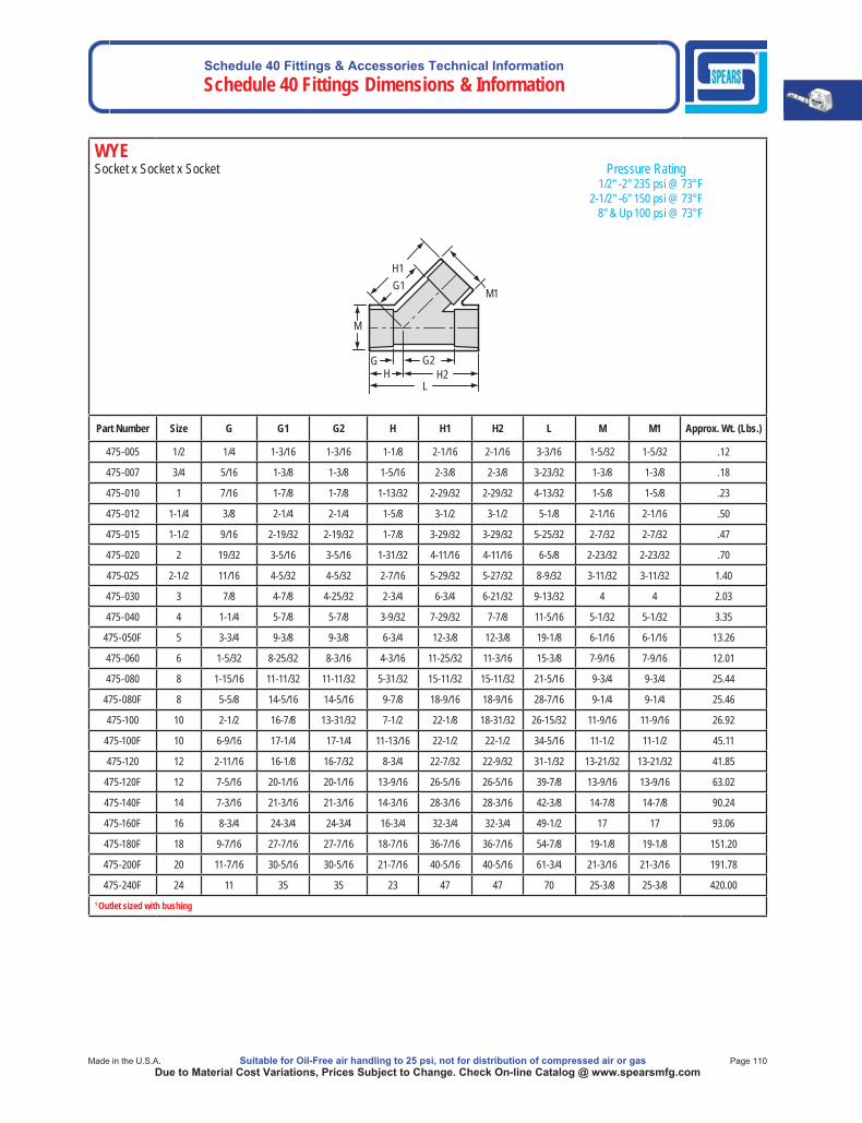
Schedule 40 Fittings & Accessories Technical InformationSchedule 40 Fittings Dimensions & Information
Made in the U.S.A. Suitable for Oil-Free air handling to 25 psi, not for distribution of compressed air or gas Page 110Due to Material Cost Variations, Prices Subject to Change. Check On-line Catalog @ www.spearsmfg.com
WYESocket x Socket x Socket Pressure Rating 1/2" -2" 235 psi @ 73°F 2-1/2" -6" 150 psi @ 73°F 8" & Up 100 psi @ 73°F
H1 G1
M
G G2 H2 H
L
M1
Part Number Size G G1 G2 H H1 H2 L M M1 Approx. Wt. (Lbs.)
475-005 1/2 1/4 1-3/16 1-3/16 1-1/8 2-1/16 2-1/16 3-3/16 1-5/32 1-5/32 .12
475-007 3/4 5/16 1-3/8 1-3/8 1-5/16 2-3/8 2-3/8 3-23/32 1-3/8 1-3/8 .18
475-010 1 7/16 1-7/8 1-7/8 1-13/32 2-29/32 2-29/32 4-13/32 1-5/8 1-5/8 .23
475-012 1-1/4 3/8 2-1/4 2-1/4 1-5/8 3-1/2 3-1/2 5-1/8 2-1/16 2-1/16 .50
475-015 1-1/2 9/16 2-19/32 2-19/32 1-7/8 3-29/32 3-29/32 5-25/32 2-7/32 2-7/32 .47
475-020 2 19/32 3-5/16 3-5/16 1-31/32 4-11/16 4-11/16 6-5/8 2-23/32 2-23/32 .70
475-025 2-1/2 11/16 4-5/32 4-5/32 2-7/16 5-29/32 5-27/32 8-9/32 3-11/32 3-11/32 1.40
475-030 3 7/8 4-7/8 4-25/32 2-3/4 6-3/4 6-21/32 9-13/32 4 4 2.03
475-040 4 1-1/4 5-7/8 5-7/8 3-9/32 7-29/32 7-7/8 11-5/16 5-1/32 5-1/32 3.35
475-050F 5 3-3/4 9-3/8 9-3/8 6-3/4 12-3/8 12-3/8 19-1/8 6-1/16 6-1/16 13.26
475-060 6 1-5/32 8-25/32 8-3/16 4-3/16 11-25/32 11-3/16 15-3/8 7-9/16 7-9/16 12.01
475-080 8 1-15/16 11-11/32 11-11/32 5-31/32 15-11/32 15-11/32 21-5/16 9-3/4 9-3/4 25.44
475-080F 8 5-5/8 14-5/16 14-5/16 9-7/8 18-9/16 18-9/16 28-7/16 9-1/4 9-1/4 25.46
475-100 10 2-1/2 16-7/8 13-31/32 7-1/2 22-1/8 18-31/32 26-15/32 11-9/16 11-9/16 26.92
475-100F 10 6-9/16 17-1/4 17-1/4 11-13/16 22-1/2 22-1/2 34-5/16 11-1/2 11-1/2 45.11
475-120 12 2-11/16 16-1/8 16-7/32 8-3/4 22-7/32 22-9/32 31-1/32 13-21/32 13-21/32 41.85
475-120F 12 7-5/16 20-1/16 20-1/16 13-9/16 26-5/16 26-5/16 39-7/8 13-9/16 13-9/16 63.02
475-140F 14 7-3/16 21-3/16 21-3/16 14-3/16 28-3/16 28-3/16 42-3/8 14-7/8 14-7/8 90.24
475-160F 16 8-3/4 24-3/4 24-3/4 16-3/4 32-3/4 32-3/4 49-1/2 17 17 93.06
475-180F 18 9-7/16 27-7/16 27-7/16 18-7/16 36-7/16 36-7/16 54-7/8 19-1/8 19-1/8 151.20
475-200F 20 11-7/16 30-5/16 30-5/16 21-7/16 40-5/16 40-5/16 61-3/4 21-3/16 21-3/16 191.78
475-240F 24 11 35 35 23 47 47 70 25-3/8 25-3/8 420.001 Outlet sized with bushing
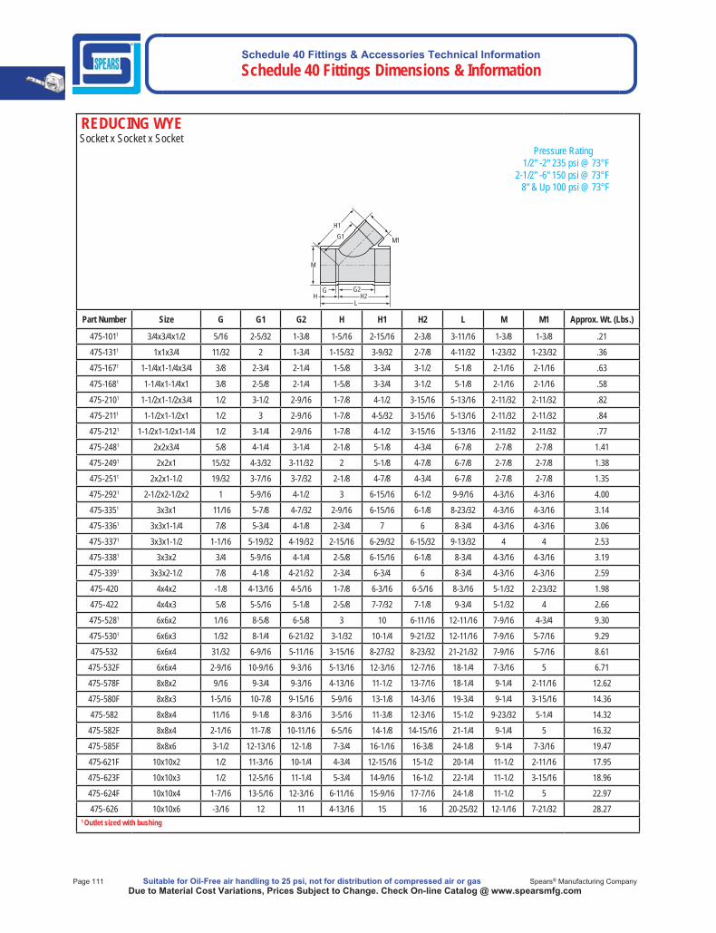
Schedule 40 Fittings & Accessories Technical Information Schedule 40 Fittings Dimensions & Information
Page 111 Suitable for Oil-Free air handling to 25 psi, not for distribution of compressed air or gas Spears® Manufacturing CompanyDue to Material Cost Variations, Prices Subject to Change. Check On-line Catalog @ www.spearsmfg.com
REDUCING WYE Socket x Socket x Socket Pressure Rating 1/2" -2" 235 psi @ 73°F 2-1/2" -6" 150 psi @ 73°F 8" & Up 100 psi @ 73°F
M
M1
G G2
L H
H1G1
H2
Part Number Size G G1 G2 H H1 H2 L M M1 Approx. Wt. (Lbs.)
475-1011 3/4x3/4x1/2 5/16 2-5/32 1-3/8 1-5/16 2-15/16 2-3/8 3-11/16 1-3/8 1-3/8 .21
475-1311 1x1x3/4 11/32 2 1-3/4 1-15/32 3-9/32 2-7/8 4-11/32 1-23/32 1-23/32 .36
475-1671 1-1/4x1-1/4x3/4 3/8 2-3/4 2-1/4 1-5/8 3-3/4 3-1/2 5-1/8 2-1/16 2-1/16 .63
475-1681 1-1/4x1-1/4x1 3/8 2-5/8 2-1/4 1-5/8 3-3/4 3-1/2 5-1/8 2-1/16 2-1/16 .58
475-2101 1-1/2x1-1/2x3/4 1/2 3-1/2 2-9/16 1-7/8 4-1/2 3-15/16 5-13/16 2-11/32 2-11/32 .82
475-2111 1-1/2x1-1/2x1 1/2 3 2-9/16 1-7/8 4-5/32 3-15/16 5-13/16 2-11/32 2-11/32 .84
475-2121 1-1/2x1-1/2x1-1/4 1/2 3-1/4 2-9/16 1-7/8 4-1/2 3-15/16 5-13/16 2-11/32 2-11/32 .77
475-2481 2x2x3/4 5/8 4-1/4 3-1/4 2-1/8 5-1/8 4-3/4 6-7/8 2-7/8 2-7/8 1.41
475-2491 2x2x1 15/32 4-3/32 3-11/32 2 5-1/8 4-7/8 6-7/8 2-7/8 2-7/8 1.38
475-2511 2x2x1-1/2 19/32 3-7/16 3-7/32 2-1/8 4-7/8 4-3/4 6-7/8 2-7/8 2-7/8 1.35
475-2921 2-1/2x2-1/2x2 1 5-9/16 4-1/2 3 6-15/16 6-1/2 9-9/16 4-3/16 4-3/16 4.00
475-3351 3x3x1 11/16 5-7/8 4-7/32 2-9/16 6-15/16 6-1/8 8-23/32 4-3/16 4-3/16 3.14
475-3361 3x3x1-1/4 7/8 5-3/4 4-1/8 2-3/4 7 6 8-3/4 4-3/16 4-3/16 3.06
475-3371 3x3x1-1/2 1-1/16 5-19/32 4-19/32 2-15/16 6-29/32 6-15/32 9-13/32 4 4 2.53
475-3381 3x3x2 3/4 5-9/16 4-1/4 2-5/8 6-15/16 6-1/8 8-3/4 4-3/16 4-3/16 3.19
475-3391 3x3x2-1/2 7/8 4-1/8 4-21/32 2-3/4 6-3/4 6 8-3/4 4-3/16 4-3/16 2.59
475-420 4x4x2 -1/8 4-13/16 4-5/16 1-7/8 6-3/16 6-5/16 8-3/16 5-1/32 2-23/32 1.98
475-422 4x4x3 5/8 5-5/16 5-1/8 2-5/8 7-7/32 7-1/8 9-3/4 5-1/32 4 2.66
475-5281 6x6x2 1/16 8-5/8 6-5/8 3 10 6-11/16 12-11/16 7-9/16 4-3/4 9.30
475-5301 6x6x3 1/32 8-1/4 6-21/32 3-1/32 10-1/4 9-21/32 12-11/16 7-9/16 5-7/16 9.29
475-532 6x6x4 31/32 6-9/16 5-11/16 3-15/16 8-27/32 8-23/32 21-21/32 7-9/16 5-7/16 8.61
475-532F 6x6x4 2-9/16 10-9/16 9-3/16 5-13/16 12-3/16 12-7/16 18-1/4 7-3/16 5 6.71
475-578F 8x8x2 9/16 9-3/4 9-3/16 4-13/16 11-1/2 13-7/16 18-1/4 9-1/4 2-11/16 12.62
475-580F 8x8x3 1-5/16 10-7/8 9-15/16 5-9/16 13-1/8 14-3/16 19-3/4 9-1/4 3-15/16 14.36
475-582 8x8x4 11/16 9-1/8 8-3/16 3-5/16 11-3/8 12-3/16 15-1/2 9-23/32 5-1/4 14.32
475-582F 8x8x4 2-1/16 11-7/8 10-11/16 6-5/16 14-1/8 14-15/16 21-1/4 9-1/4 5 16.32
475-585F 8x8x6 3-1/2 12-13/16 12-1/8 7-3/4 16-1/16 16-3/8 24-1/8 9-1/4 7-3/16 19.47
475-621F 10x10x2 1/2 11-3/16 10-1/4 4-3/4 12-15/16 15-1/2 20-1/4 11-1/2 2-11/16 17.95
475-623F 10x10x3 1/2 12-5/16 11-1/4 5-3/4 14-9/16 16-1/2 22-1/4 11-1/2 3-15/16 18.96
475-624F 10x10x4 1-7/16 13-5/16 12-3/16 6-11/16 15-9/16 17-7/16 24-1/8 11-1/2 5 22.97
475-626 10x10x6 -3/16 12 11 4-13/16 15 16 20-25/32 12-1/16 7-21/32 28.271 Outlet sized with bushing
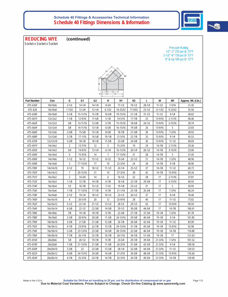
Schedule 40 Fittings & Accessories Technical InformationSchedule 40 Fittings Dimensions & Information
Made in the U.S.A. Suitable for Oil-Free air handling to 25 psi, not for distribution of compressed air or gas Page 112Due to Material Cost Variations, Prices Subject to Change. Check On-line Catalog @ www.spearsmfg.com
REDUCING WYE Socket x Socket x Socket Pressure Rating 1/2" -2" 235 psi @ 73°F 2-1/2" -6" 150 psi @ 73°F 8" & Up 100 psi @ 73°F
M
M1
G G2
L H
H1G1
H2
Part Number Size G G1 G2 H H1 H2 L M M1 Approx. Wt. (Lbs.)475-626F 10x10x6 3-1/2 14-1/4 14-1/4 8-3/4 17-1/2 19-1/2 28-1/4 11-1/2 7-3/16 21.45475-628 10x10x8 1-7/32 12-3/4 12-1/4 6-7/32 16-25/32 17-9/32 23-1/2 12-1/32 9-23/32 35.50
475-628F 10x10x8 5-1/8 15-11/16 15-7/8 10-3/8 19-15/16 21-1/8 31-1/2 11-1/2 9-1/4 28.02475-661F 12x12x2 1-1/8 12-9/16 11-5/8 5-1/8 14-5/16 17-7/8 23 13-9/16 2-11/16 40.46475-663F 12x12x3 3/8 13-11/16 12-3/8 5-7/8 15-15/16 18-5/8 24-1/2 13-9/16 3-15/16 28.74475-664F 12x12x4 3/8 14-11/16 13-1/8 6-5/8 16-15/16 19-3/8 26 13-9/16 5 23.93475-666F 12x12x6 2-3/8 15-5/8 15-1/8 8-5/8 18-7/8 21-3/8 30 13-9/16 7-3/16 28.92475-668F 12x12x8 3-7/8 17-1/16 16-5/8 10-1/8 21-5/16 22-7/8 33 13-9/16 9-1/4 45.53475-670F 12x12x10 5-3/8 18-1/8 18-1/8 11-5/8 23-3/8 24-3/8 36 13-9/16 11-1/2 40.69475-691F 14x14x2 2 13-7/16 12 5 15-3/16 19 24 14-7/8 2-11/16 29.36475-693F 14x14x3 3/4 14-9/16 13-1/4 6-1/4 16-13/16 20-1/4 26-1/2 14-7/8 3-15/16 33.06475-694F 14x14x4 0 15-9/16 14 7 17-13/16 21 28 14-7/8 5 37.45475-696F 14x14x6 1-1/2 16-1/2 15-1/2 8-1/2 19-3/4 22-1/2 31 14-7/8 7-3/16 48.96475-698F 14x14x8 3 17-15/16 17 10 22-3/16 24 34 14-7/8 9-1/8 48.96475-700F 14x14x10 4-1/2 19 18-1/2 11-1/2 24-1/4 25-1/2 37 14-7/8 11-1/2 60.73475-702F 14x14x12 7 20-15/16 21 14 27-3/16 28 42 14-7/8 13-9/16 69.34475-751F 16x16x2 2 14-3/4 14 6 16-1/2 22 28 17 2-11/16 37.81475-753F 16x16x3 1-1/8 15-7/8 14-7/8 6-7/8 18-1/8 22-7/8 29-3/4 17 3-15/16 40.93475-754F 16x16x4 1/2 16-7/8 15-1/2 7-1/2 19-1/8 23-1/2 31 17 5 50.95475-756F 16x16x6 1-7/8 17-13/16 17-7/8 9-7/8 21-1/16 25-7/8 35-3/4 17 7-3/16 60.24475-758F 16x16x8 2-1/2 19-1/4 18-1/2 10-1/2 23-1/2 26-1/2 37 17 9-1/4 70.40475-760F 16x16x10 4 20-5/16 20 12 25-9/16 28 40 17 11-1/2 73.02475-762F 16x16x12 5-1/2 22-1/4 21-1/2 13-1/2 28-1/2 29-1/2 43 17 13-9/16 90.59475-764F 16x16x14 6-3/8 22-1/2 22-3/8 14-3/8 29-1/2 30-3/8 44-3/4 17 14-7/8 100.41475-786F 18x18x6 7/8 19-1/8 18-7/8 9-7/8 22-3/8 27-7/8 37-3/4 19-1/8 7-3/16 81.78475-788F 18x18x8 2-3/8 20-9/16 20-3/8 11-3/8 24-13/16 29-3/8 40-3/4 19-1/8 9-1/4 101.85475-790F 18x18x10 3-3/8 21-5/8 21-3/8 12-3/8 26-7/8 30-3/8 42-3/4 19-1/8 11-1/2 83.99475-792F 18x18x12 4-7/8 23-9/16 22-7/8 13-7/8 29-13/16 31-7/8 45-3/4 19-1/8 13-9/16 92.98475-794F 18x18x14 5-3/8 23-13/16 23-3/8 14-3/8 30-13/16 32-3/8 46-3/4 19-1/8 14-7/8 116.88475-796F 18x18x16 7-7/8 26-1/16 25-7/8 16-7/8 34-1/16 34-7/8 51-3/4 19-1/8 17 121.63475-816F 20x20x6 1/8 20-1/2 19-7/8 9-7/8 23-3/4 29-7/8 39-3/4 21-3/16 7-3/16 101.52475-818F 20x20x8 1-3/8 21-15/16 21-3/8 11-3/8 26-3/16 31-3/8 42-3/4 21-3/16 9-1/4 109.36475-820F 20x20x10 2-3/8 23 22-3/8 12-3/8 28-1/4 32-3/8 44-3/4 21-3/16 11-1/2 120.53475-822F 20x20x12 4-3/8 24-15/16 24-3/8 14-3/8 31-3/16 34-3/8 48-3/4 21-3/16 13-9/16 135.66475-824F 20x20x14 4-7/8 25-3/16 24-7/8 14-7/8 32-3/16 34-7/8 49-3/4 21-3/16 14-7/8 129.00

Schedule 40 Fittings & Accessories Technical Information Schedule 40 Fittings Dimensions & Information
Page 113 Suitable for Oil-Free air handling to 25 psi, not for distribution of compressed air or gas Spears® Manufacturing CompanyDue to Material Cost Variations, Prices Subject to Change. Check On-line Catalog @ www.spearsmfg.com
REDUCING WYE Socket x Socket x Socket Pressure Rating 1/2" -2" 235 psi @ 73°F 2-1/2" -6" 150 psi @ 73°F 8" & Up 100 psi @ 73°F
M
M1
G G2
L H
H1G1
H2
Part Number Size G G1 G2 H H1 H2 L M M1 Approx. Wt. (Lbs.)475-826F 20x20x16 6-3/8 27-7/16 26-3/8 16-3/8 35-7/16 36-3/8 52-3/4 21-3/16 17 161.54475-828F 20x20x18 7-7/8 28-13/16 27-7/8 17-7/8 37-13/16 37-7/8 55-3/4 21-3/16 19-1/8 158.46475-906F 24x24x6 1-1/4 23-3/16 22-3/4 10-3/4 26-7/16 34-3/4 45-1/2 25-3/8 7-3/16 149.00475-908F 24x24x8 1/4 24-5/8 24-1/4 12-1/4 28-7/8 36-1/4 48-1/2 25-3/8 9-1/4 165.00475-910F 24x24x10 1-3/8 25-11/16 25-3/8 13-3/8 30-15/16 37-3/8 50-3/4 25-3/8 11-1/2 176.10475-912F 24x24x12 3-1/4 27-5/8 27-1/4 15-1/4 33-7/8 39-1/4 54-1/2 25-3/8 13-9/16 153.58475-914F 24x24x14 4 27-7/8 28 16 34-7/8 40 56 25-3/8 14-7/8 184.50475-916F 24x24x16 6-3/8 30-1/8 30-3/8 18-3/8 38-1/8 42-3/8 60-3/4 25-3/8 17 185.70475-918F 24x24x18 7-7/8 31-1/2 31-7/8 19-7/8 40-1/2 43-7/8 63-3/4 25-3/8 19-1/8 185.70475-920F 24x24x20 9-1/8 33 33-1/8 21-1/8 43 45-1/8 66-1/4 25-3/8 21-3/16 232.49
DOUBLE WYESocket x Socket x Socket x Socket Pressure Rating 150 psi @ 73°F
M1
L H2
G2
G H
M
G1 H1
Part Number Size G G1 G2 H H1 H2 L M M1 Approx. Wt. (Lbs.)
476-020F 2 3-5/16 5-11/16 5-11/16 4-11/16 7-1/16 7-1/16 11-3/4 2-3/4 2-3/4 1.25
476-030F 3 4-7/8 8-3/8 8-3/8 6-3/4 10-1/14 10-1/4 17 4 4 5.42
476-040F 4 4-5/8 9-3/4 9-1/8 6-7/8 11-11/16 11-3/8 18-1/4 5 5-1/16 10.09
476-060F 6 4-7/8 11-1/2 11-1/2 8-1/8 14-3/4 14-3/4 22-7/8 7-3/16 7-3/16 20.91
476-080F 8 5-5/8 14-5/16 14-5/16 9-7/8 18-9/16 18-9/16 28-7/16 9-1/4 9-1/4 25.02
476-100F 10 6-9/16 17-1/4 17-1/4 11-13/16 22-1/2 22-1/2 34-5/16 11-1/2 11-1/2 37.91
476-120F 12 7-5/16 20-1/16 20-1/16 13-9/16 26-5/16 26-5/16 39-7/8 13-9/16 13-9/16 63.02
476-140F 14 7-3/16 21-3/16 21-3/16 14-3/16 28-3/16 28-3/16 42-3/8 14-7/8 14-7/8 110.64
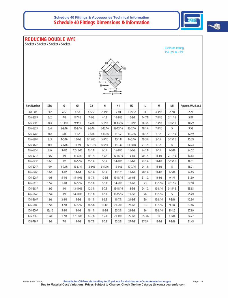
Schedule 40 Fittings & Accessories Technical InformationSchedule 40 Fittings Dimensions & Information
Made in the U.S.A. Suitable for Oil-Free air handling to 25 psi, not for distribution of compressed air or gas Page 114Due to Material Cost Variations, Prices Subject to Change. Check On-line Catalog @ www.spearsmfg.com
REDUCING DOUBLE WYESocket x Socket x Socket x Socket Pressure Rating 150 psi @ 73°F
M1
L H2
G2
G H
M
G1 H1
Part Number Size G G1 G2 H H1 H2 L M M1 Approx. Wt. (Lbs.)
476-338 3x2 7/32 4-1/4 4-1/32 2-3/32 5-3/4 5-29/32 8 4-3/16 2-7/8 2.27
476-528F 6x2 7/8 8-7/16 7-1/2 4-1/8 10-3/16 10-3/4 14-7/8 7-3/16 2-11/16 5.87
476-530F 6x3 1-13/16 9-9/16 8-7/16 5-1/16 11-13/16 11-11/16 16-3/4 7-3/16 3-15/16 10.29
476-532F 6x4 2-9/16 10-9/16 9-3/16 5-13/16 12-13/16 12-7/16 18-1/4 7-3/16 5 9.52
476-578F 8x2 9/16 9-3/4 9-3/16 4-13/16 11-1/2 13-7/16 18-1/4 9-1/4 2-11/16 12.49
476-580F 8x3 1-5/16 10-7/8 9-15/16 5-9/16 13-1/8 14-3/16 19-3/4 9-1/4 3-15/16 15.79
476-582F 8x4 2-1/16 11-7/8 10-11/16 6-5/16 14-1/8 14-15/16 21-1/4 9-1/4 5 12.73
476-585F 8x6 3-1/2 12-13/16 12-1/8 7-3/4 16-1/16 16-3/8 24-1/8 9-1/4 7-3/16 24.52
476-621F 10x2 1/2 11-3/16 10-1/4 4-3/4 12-15/16 15-1/2 20-1/4 11-1/2 2-11/16 13.93
476-623F 10x3 1/2 12-5/16 11-1/4 5-3/4 14-9/16 16-1/2 22-1/4 11-1/2 3-15/16 16.31
476-624F 10x4 1-7/16 13-5/16 12-3/16 6-11/16 15-9/16 17-7/16 24-1/8 11-1/2 5 18.71
476-626F 10x6 3-1/2 14-1/4 14-1/4 8-3/4 17-1/2 19-1/2 28-1/4 11-1/2 7-3/16 24.65
476-628F 10x8 5-1/8 15-11/16 15-7/8 10-3/8 19-15/16 21-1/8 31-1/2 11-1/2 9-1/4 31.59
476-661F 12x2 1-1/8 12-9/16 11-5/8 5-1/8 14-5/16 17-7/8 23 13-9/16 2-11/16 32.18
476-663F 12x3 3/8 13-11/16 12-3/8 5-7/8 15-15/16 18-5/8 24-1/2 13-9/16 3-15/16 35.93
476-664F 12x4 3/8 14-11/16 13-1/8 6-5/8 16-15/16 19-3/8 26 13-9/16 5 25.49
476-666F 12x6 2-3/8 15-5/8 15-1/8 8-5/8 18-7/8 21-3/8 30 13-9/16 7-3/16 42.56
476-668F 12x8 3-7/8 17-1/16 16-5/8 10-1/8 21-5/16 22-7/8 33 13-9/16 9-1/4 37.86
476-670F 12x10 5-3/8 18-1/8 18-1/8 11-5/8 23-3/8 24-3/8 36 13-9/16 11-1/2 67.89
476-756F 16x6 1-7/8 17-13/16 17-7/8 9-7/8 21-1/16 25-7/8 35-3/4 17 7-3/16 64.27
476-786F 18x6 7/8 19-1/8 18-7/8 9-7/8 22-3/8 27-7/8 37-3/4 19-1/8 7-3/16 91.45
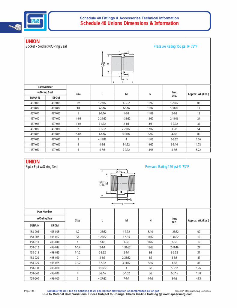
Schedule 40 Fittings & Accessories Technical Information Schedule 40 Unions Dimensions & Information
Page 115 Suitable for Oil-Free air handling to 25 psi, not for distribution of compressed air or gas Spears® Manufacturing CompanyDue to Material Cost Variations, Prices Subject to Change. Check On-line Catalog @ www.spearsmfg.com
UNIONFipt x Fipt w/O-ring Seal Pressure Rating 150 psi @ 73°F
L N
MNUT O.D.
Part Number
Size L M N NutO.D. Approx. Wt. (Lbs.)w/O-ring Seal
BUNA-N EPDM
458-005 498-005 1/2 1-25/32 1-3/32 5/16 1-23/32 .09
458-007 498-007 3/4 1-25/32 1-5/16 11/32 1-31/32 .12
458-010 498-010 1 2-1/8 1-5/8 11/32 2-3/8 .19
458-012 498-012 1-1/4 2-1/4 1-31/32 13/32 2-11/16 .24
458-015 498-015 1-1/2 2-9/32 2-1/4 3/8 3-3/32 .31
458-020 498-020 2 2-1/2 2-23/32 1/2 3-5/8 .47
458-025 498-025 2-1/2 3-5/32 3-11/32 9/16 4-3/8 .86
458-030 498-030 3 3-13/32 4 5/8 5-3/32 1.26
458-040 498-040 4 3-9/16 5-1/32 5/8 6-3/16 1.74
458-060 498-060 6 4-27/32 7-1/4 1-1/2 8-7/8 4.83
UNIONSocket x Socket w/O-ring Seal Pressure Rating 150 psi @ 73°F
N L
NUT O.D. M
Part Number
Size L M N NutO.D. Approx. Wt. (Lbs.)w/O-ring Seal
BUNA-N EPDM
457-005 497-005 1/2 1-27/32 1-3/32 11/32 1-23/32 .08
457-007 497-007 3/4 2-3/16 1-5/16 11/32 1-31/32 .12
457-010 497-010 1 2-7/16 1-5/8 11/32 2-3/8 .18
457-012 497-012 1-1/4 2-29/32 1-31/32 13/32 2-11/16 .24
457-015 497-015 1-1/2 3-1/32 2-1/4 3/8 3-3/32 .32
457-020 497-020 2 3-9/32 2-23/32 17/32 3-5/8 .54
457-025 497-025 2-1/2 4-1/16 3-11/32 9/16 4-3/8 .85
457-030 497-030 3 4-11/32 4 11/16 5-3/32 1.26
457-040 497-040 4 4-5/8 5-1/32 19/32 6-3/16 1.78
457-060 497-060 6 6-7/8 7-9/32 13/16 8-7/8 5.22
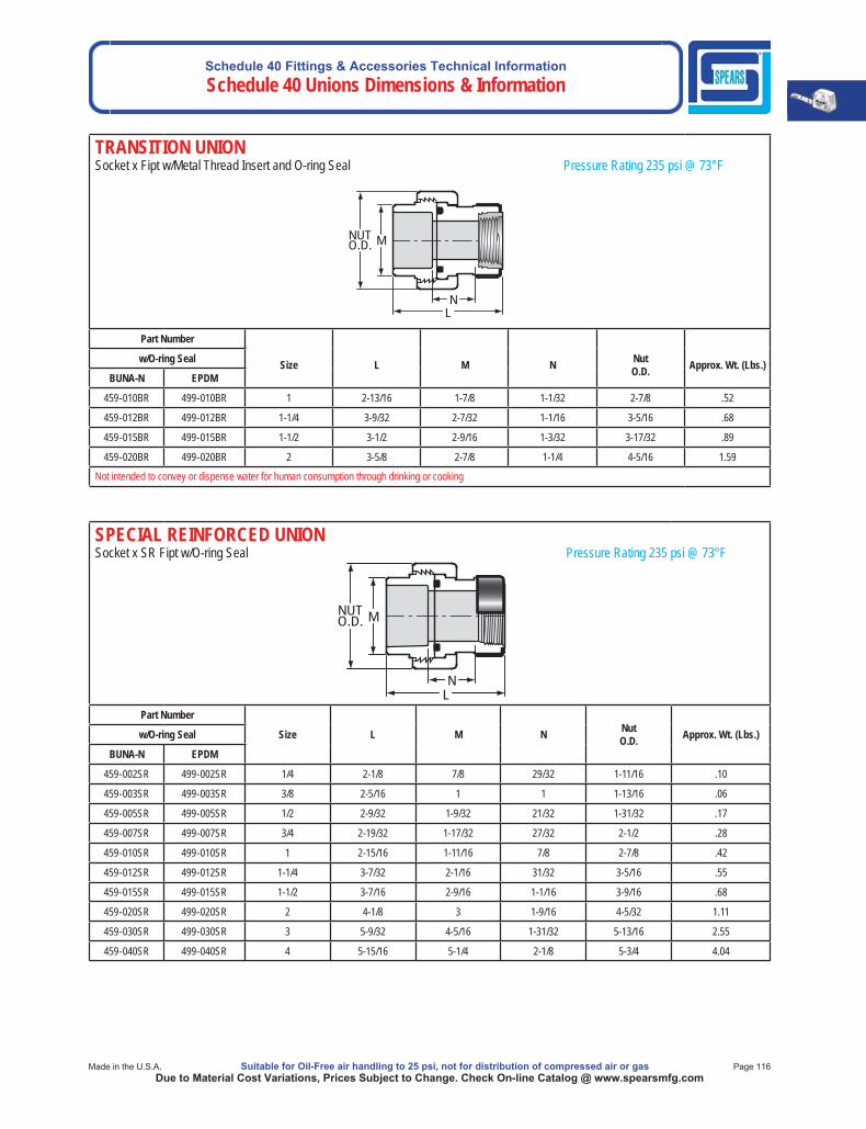
Schedule 40 Fittings & Accessories Technical InformationSchedule 40 Unions Dimensions & Information
Made in the U.S.A. Suitable for Oil-Free air handling to 25 psi, not for distribution of compressed air or gas Page 116Due to Material Cost Variations, Prices Subject to Change. Check On-line Catalog @ www.spearsmfg.com
SPECIAL REINFORCED UNIONSocket x SR Fipt w/O-ring Seal Pressure Rating 235 psi @ 73°F
LN
MNUTO.D.
Part Number
Size L M N NutO.D. Approx. Wt. (Lbs.)w/O-ring Seal
BUNA-N EPDM
459-002SR 499-002SR 1/4 2-1/8 7/8 29/32 1-11/16 .10
459-003SR 499-003SR 3/8 2-5/16 1 1 1-13/16 .06
459-005SR 499-005SR 1/2 2-9/32 1-9/32 21/32 1-31/32 .17
459-007SR 499-007SR 3/4 2-19/32 1-17/32 27/32 2-1/2 .28
459-010SR 499-010SR 1 2-15/16 1-11/16 7/8 2-7/8 .42
459-012SR 499-012SR 1-1/4 3-7/32 2-1/16 31/32 3-5/16 .55
459-015SR 499-015SR 1-1/2 3-7/16 2-9/16 1-1/16 3-9/16 .68
459-020SR 499-020SR 2 4-1/8 3 1-9/16 4-5/32 1.11
459-030SR 499-030SR 3 5-9/32 4-5/16 1-31/32 5-13/16 2.55
459-040SR 499-040SR 4 5-15/16 5-1/4 2-1/8 5-3/4 4.04
TRANSITION UNIONSocket x Fipt w/Metal Thread Insert and O-ring Seal Pressure Rating 235 psi @ 73°F
LN
MNUTO.D.
Part Number
Size L M N NutO.D. Approx. Wt. (Lbs.)w/O-ring Seal
BUNA-N EPDM
459-010BR 499-010BR 1 2-13/16 1-7/8 1-1/32 2-7/8 .52
459-012BR 499-012BR 1-1/4 3-9/32 2-7/32 1-1/16 3-5/16 .68
459-015BR 499-015BR 1-1/2 3-1/2 2-9/16 1-3/32 3-17/32 .89
459-020BR 499-020BR 2 3-5/8 2-7/8 1-1/4 4-5/16 1.59
Not intended to convey or dispense water for human consumption through drinking or cooking
Schedule 40 Fittings & Accessories Technical Information Schedule 40 Saddles Dimensions & Information
Page 117 Suitable for Oil-Free air handling to 25 psi, not for distribution of compressed air or gas Spears® Manufacturing CompanyDue to Material Cost Variations, Prices Subject to Change. Check On-line Catalog @ www.spearsmfg.com
When Assembling Spears® Saddles to PVC pipe, Spears® Manufacturing Company recommends Spears® PVC-19 Solvent Cement and Spears® Primer-68/Primer-70 or equivalent. Although good connections may be accomplished without saddle straps, Spears® Manufacturing Company recommends the use of clamp or strap device during the assembly step to ensure good compression between the pipe and fitting surfaces as the solvent cures. Solvent cemented saddles are non pressure rated. For additional information, contact Spears® TechnicalService.
LARGE DIAMETER NPR SADDLE INSTALLATIONSpears® Large Diameter Non-Pressure Rated (NPR) Saddles are designed for use with PVC pipe in open ended, drainage applications. A supplemental clamping strap must be used to eliminate gaps and insure good compression and proper fit between the pipe and the saddle surfaces as the solvent cement cures. Clamping straps/kits are commercially available and are not included with saddle. Proper installationrequires adequate application of solvent cement and immediate clamping in position with the clamping straps. Additional Items Needed Marking Pen 60-Grit Sandpaper Large Roller Applicator1/2" Wrench Primer (Spears® Primer-68/Primer-70) Clamping Straps Hole Saw Solvent Cement (Spears® PVC-19)Power Drill Primer & Cement Use ContainersStep 1: Dry-fit Saddle, Mark Location of Saddle and Hole, Prepare Clamping StrapsCheck for adequate clearance of saddle and that clamping straps can be installed. Position saddle on pipe aligning branch and desiredhole centers. Mark outline of saddle, branch hole and center. Prepare two (2) clamping straps of appropriate length (one strap will be used on each side of branch).Step 2: Cut Hole in PipeRemove saddle; verify system is drained. Drill hole at marked center location using appropriate size hole saw.Step 3: Sand Pipe and Saddle Contact Areas with 60-Grit SandpaperThoroughly rough up the marked outline area on the pipe and on the underside of the saddle using 60-grit sandpaper. Sand in direction of pipe (parallel), then crosswise of pipe (perpendicular) until rough and all gloss is removed. Give attention to area around the branch on both pipe and saddle.Step 4: Apply Primer to Pipe and SaddleWork several coats into the roughened pipe area and underside of saddle, giving attention to the area around the branch on both. Primer until the surfaces are softened using a large roller applicator. Step 5: Apply a Liberal Quantity of Cement to Pipe and Saddle Apply several coats (minimum 3) one after the other to build up cement on pipe and saddle contact areas. Avoid removing previous coat with each application. DO NOT allow cement to dry out between coats. Again, give attention to area around the branch on both pipe and saddle. For threaded saddles, avoid runs or drips in the branch fitting threads.Step 6: Immediately Install Saddle and Tighten Clamping StrapsPosition saddle and locate clamping straps midway between branch and end on each side of branch. This should be done immediately while cement is still wet. Avoid excessive movement that might dislocate proper positioning (assistance is recommended). Tighten straps tight to firmly press saddle onto pipe. A thick glue-bead should be forced out around the saddle edges and inside the branch joint. If no bead, quickly remove saddle and apply more cement.Step 7: Allow Cement Joint to Cure Cure for same time and conditions as required for standard solvent cement pipe joints of the same size in the system.
Snap-On Saddle Installation Instructions • The surface to be joined must be wiped clean.• Using an appropriate applicator, apply a coat of primer to the fitting and pipe.• While the primer is still wet, apply a generous coat of medium bodied cement first to the pipe, then to the fitting and then to the pipe
again, covering an area of the pipe slightly larger than the saddle.• Without delay, push the saddle onto the pipe and rotate the fitting approximately 15° in each direction to evenly distribute the cement.• Allow cement to cure.• Drill fitting and pipe with the recommended size hole saw.• Remove debris from the line.• Follow all safe handling precautions.Solvent cemented saddles are non pressure rated. For additional information, contact Spears® Technical Service.
SADDLES & SNAP-ON SADDLES
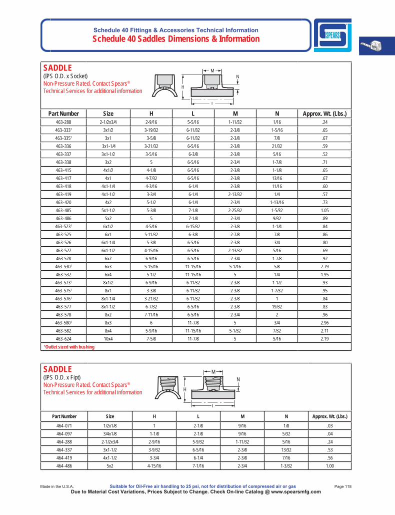
Schedule 40 Fittings & Accessories Technical InformationSchedule 40 Saddles Dimensions & Information
Made in the U.S.A. Suitable for Oil-Free air handling to 25 psi, not for distribution of compressed air or gas Page 118Due to Material Cost Variations, Prices Subject to Change. Check On-line Catalog @ www.spearsmfg.com
SADDLE(IPS O.D. x Socket)Non-Pressure Rated. Contact Spears®
Technical Services for additional information
Part Number Size H L M N Approx. Wt. (Lbs.)463-288 2-1/2x3/4 2-9/16 5-5/16 1-11/32 1/16 .24463-3331 3x1/2 3-19/32 6-11/32 2-3/8 1-5/16 .65463-3351 3x1 3-5/8 6-11/32 2-3/8 7/8 .67463-336 3x1-1/4 3-21/32 6-5/16 2-3/8 21/32 .59463-337 3x1-1/2 3-5/16 6-3/8 2-3/8 5/16 .52463-338 3x2 5 6-5/16 2-3/4 1-7/8 .71463-415 4x1/2 4-1/8 6-5/16 2-3/8 1-1/8 .65463-417 4x1 4-7/32 6-5/16 2-3/8 13/16 .67463-418 4x1-1/4 4-3/16 6-1/4 2-3/8 11/16 .60463-419 4x1-1/2 3-3/4 6-1/4 2-13/32 1/4 .57463-420 4x2 5-1/2 6-1/4 2-3/4 1-13/16 .73463-485 5x1-1/2 5-3/8 7-1/8 2-25/32 1-5/32 1.05463-486 5x2 5 7-1/8 2-3/4 9/32 .89463-5231 6x1/2 4-5/16 6-15/32 2-3/8 1-1/4 .84463-525 6x1 5-11/32 6-3/8 2-7/8 7/8 .86463-526 6x1-1/4 5-3/8 6-5/16 2-3/8 3/4 .80463-527 6x1-1/2 4-15/16 6-5/16 2-13/32 5/16 .69463-528 6x2 6-9/16 6-5/16 2-3/4 1-7/8 .92463-5301 6x3 5-15/16 11-15/16 5-1/16 5/8 2.79463-532 6x4 5-1/2 11-15/16 5 1/4 1.95463-5731 8x1/2 6-9/16 6-11/32 2-3/8 1-1/2 .93463-5751 8x1 3-3/8 6-11/32 2-3/8 1-7/32 .95463-5761 8x1-1/4 3-21/32 6-11/32 2-3/8 1 .84463-577 8x1-1/2 6-7/32 6-5/16 2-3/8 19/32 .83463-578 8x2 7-11/16 6-5/16 2-3/4 2 .96463-5801 8x3 6 11-7/8 5 3/4 2.96463-582 8x4 5-9/16 11-15/16 5-1/32 7/32 2.11463-624 10x4 7-5/8 11-7/8 5 5/16 2.19
1Outlet sized with bushing
N
H
M
L
SADDLE(IPS O.D. x Fipt)Non-Pressure Rated. Contact Spears®
Technical Services for additional information
Part Number Size H L M N Approx. Wt. (Lbs.)
464-071 1/2x1/8 1 2-1/8 9/16 1/8 .03464-097 3/4x1/8 1-1/8 2-1/8 9/16 5/32 .04464-288 2-1/2x3/4 2-9/16 5-9/32 1-11/32 5/16 .24464-337 3x1-1/2 3-9/32 6-5/16 2-3/8 13/32 .53464-419 4x1-1/2 3-3/4 6-1/4 2-3/8 7/16 .56464-486 5x2 4-15/16 7-1/16 2-3/4 1-3/32 1.00
M
L
N
H
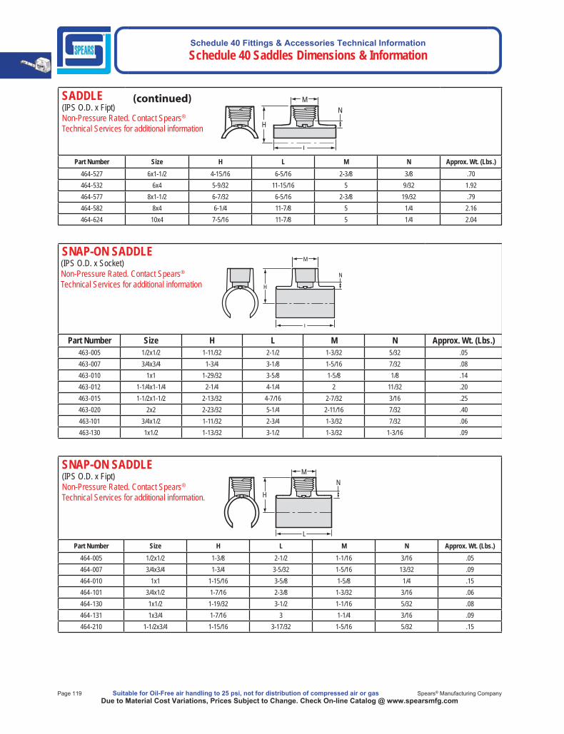
Schedule 40 Fittings & Accessories Technical Information Schedule 40 Saddles Dimensions & Information
Page 119 Suitable for Oil-Free air handling to 25 psi, not for distribution of compressed air or gas Spears® Manufacturing CompanyDue to Material Cost Variations, Prices Subject to Change. Check On-line Catalog @ www.spearsmfg.com
SADDLE(IPS O.D. x Fipt)Non-Pressure Rated. Contact Spears®
Technical Services for additional information
Part Number Size H L M N Approx. Wt. (Lbs.)464-527 6x1-1/2 4-15/16 6-5/16 2-3/8 3/8 .70464-532 6x4 5-9/32 11-15/16 5 9/32 1.92464-577 8x1-1/2 6-7/32 6-5/16 2-3/8 19/32 .79464-582 8x4 6-1/4 11-7/8 5 1/4 2.16464-624 10x4 7-5/16 11-7/8 5 1/4 2.04
M
L
N
H
SNAP-ON SADDLE (IPS O.D. x Socket) Non-Pressure Rated. Contact Spears®
Technical Services for additional information
Part Number Size H L M N Approx. Wt. (Lbs.)463-005 1/2x1/2 1-11/32 2-1/2 1-3/32 5/32 .05463-007 3/4x3/4 1-3/4 3-1/8 1-5/16 7/32 .08463-010 1x1 1-29/32 3-5/8 1-5/8 1/8 .14463-012 1-1/4x1-1/4 2-1/4 4-1/4 2 11/32 .20463-015 1-1/2x1-1/2 2-13/32 4-7/16 2-7/32 3/16 .25463-020 2x2 2-23/32 5-1/4 2-11/16 7/32 .40463-101 3/4x1/2 1-11/32 2-3/4 1-3/32 7/32 .06463-130 1x1/2 1-13/32 3-1/2 1-3/32 1-3/16 .09
M
N
H
L
SNAP-ON SADDLE(IPS O.D. x Fipt)Non-Pressure Rated. Contact Spears®
Technical Services for additional information.
Part Number Size H L M N Approx. Wt. (Lbs.)464-005 1/2x1/2 1-3/8 2-1/2 1-1/16 3/16 .05464-007 3/4x3/4 1-3/4 3-5/32 1-5/16 13/32 .09464-010 1x1 1-15/16 3-5/8 1-5/8 1/4 .15464-101 3/4x1/2 1-7/16 2-3/8 1-3/32 3/16 .06464-130 1x1/2 1-19/32 3-1/2 1-1/16 5/32 .08464-131 1x3/4 1-7/16 3 1-1/4 3/16 .09464-210 1-1/2x3/4 1-15/16 3-17/32 1-5/16 5/32 .15
MN
H
L
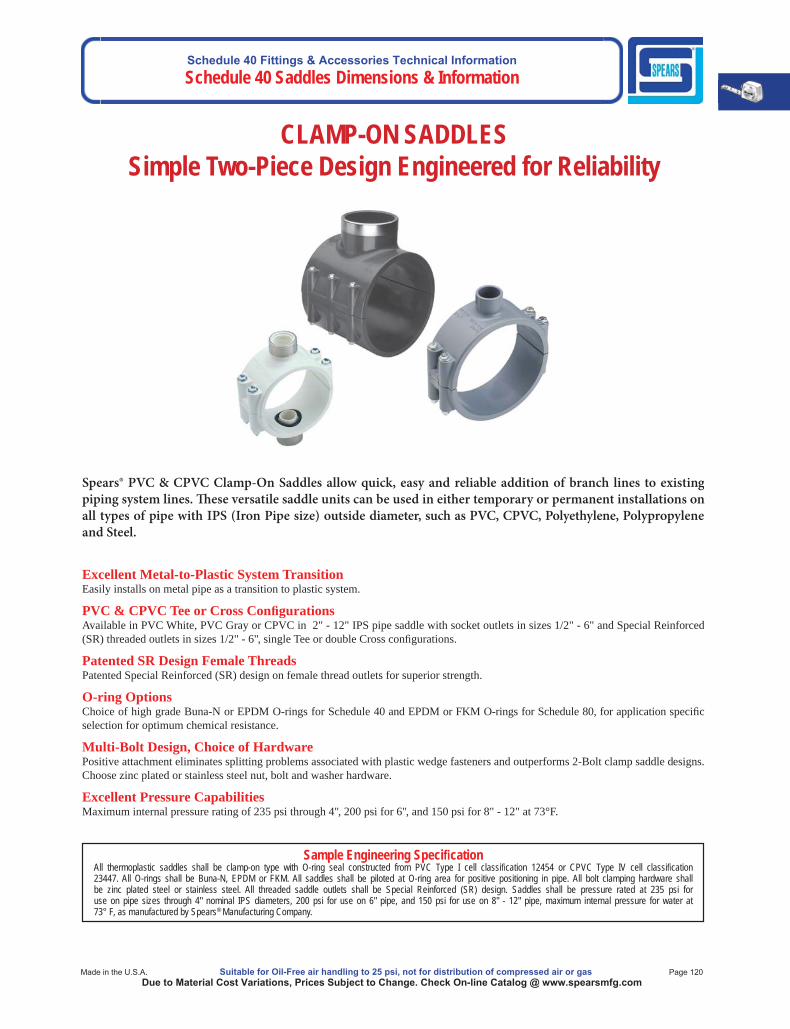
Schedule 40 Fittings & Accessories Technical InformationSchedule 40 Saddles Dimensions & Information
Made in the U.S.A. Suitable for Oil-Free air handling to 25 psi, not for distribution of compressed air or gas Page 120Due to Material Cost Variations, Prices Subject to Change. Check On-line Catalog @ www.spearsmfg.com
Excellent Metal-to-Plastic System TransitionEasily installs on metal pipe as a transition to plastic system.
PVC & CPVC Tee or Cross Con gurationsAvailable in PVC White, PVC Gray or CPVC in 2" - 12" IPS pipe saddle with socket outlets in sizes 1/2" - 6" and Special Reinforced (SR) threaded outlets in sizes 1/2" - 6", single Tee or double Cross con gurations.
Patented SR Design Female ThreadsPatented Special Reinforced (SR) design on female thread outlets for superior strength.
O-ring OptionsChoice of high grade Buna-N or EPDM O-rings for Schedule 40 and EPDM or FKM O-rings for Schedule 80, for application speci cselection for optimum chemical resistance.
Multi-Bolt Design, Choice of HardwarePositive attachment eliminates splitting problems associated with plastic wedge fasteners and outperforms 2-Bolt clamp saddle designs.Choose zinc plated or stainless steel nut, bolt and washer hardware.
Excellent Pressure CapabilitiesMaximum internal pressure rating of 235 psi through 4", 200 psi for 6", and 150 psi for 8" - 12" at 73°F.
Sample Engineering Speci cationAll thermoplastic saddles shall be clamp-on type with O-ring seal constructed from PVC Type I cell classi cation 12454 or CPVC Type IV cell classi cation 23447. All O-rings shall be Buna-N, EPDM or FKM. All saddles shall be piloted at O-ring area for positive positioning in pipe. All bolt clamping hardware shall be zinc plated steel or stainless steel. All threaded saddle outlets shall be Special Reinforced (SR) design. Saddles shall be pressure rated at 235 psi for use on pipe sizes through 4" nominal IPS diameters, 200 psi for use on 6" pipe, and 150 psi for use on 8" - 12" pipe, maximum internal pressure for water at 73° F, as manufactured by Spears® Manufacturing Company.
Spears® PVC & CPVC Clamp-On Saddles allow quick, easy and reliable addition of branch lines to existing piping system lines. Th ese versatile saddle units can be used in either temporary or permanent installations onall types of pipe with IPS (Iron Pipe size) outside diameter, such as PVC, CPVC, Polyethylene, Polypropylene and Steel.
CLAMP-ON SADDLESSimple Two-Piece Design Engineered for Reliability
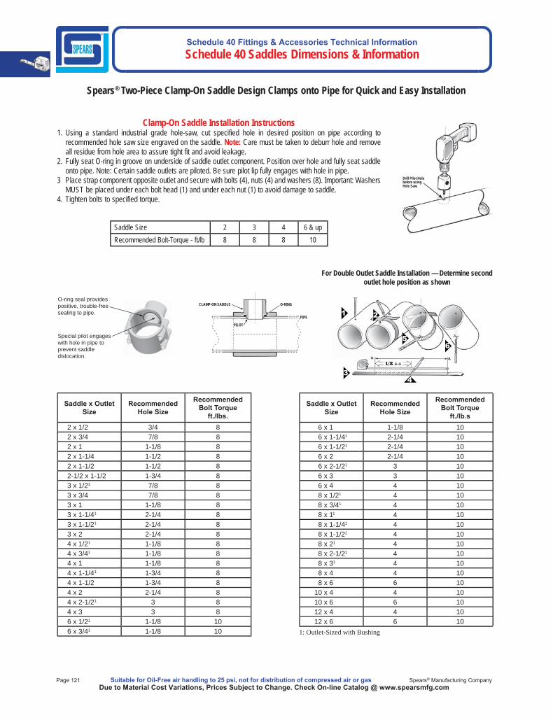
Schedule 40 Fittings & Accessories Technical Information Schedule 40 Saddles Dimensions & Information
Page 121 Suitable for Oil-Free air handling to 25 psi, not for distribution of compressed air or gas Spears® Manufacturing CompanyDue to Material Cost Variations, Prices Subject to Change. Check On-line Catalog @ www.spearsmfg.com
Saddle x Outlet Size
Recommended Hole Size
Recommended Bolt Torque
ft./lbs.2 x 1/2 3/4 82 x 3/4 7/8 82 x 1 1-1/8 82 x 1-1/4 1-1/2 82 x 1-1/2 1-1/2 82-1/2 x 1-1/2 1-3/4 83 x 1/21 7/8 83 x 3/4 7/8 83 x 1 1-1/8 83 x 1-1/41 2-1/4 83 x 1-1/21 2-1/4 83 x 2 2-1/4 84 x 1/21 1-1/8 84 x 3/41 1-1/8 84 x 1 1-1/8 84 x 1-1/41 1-3/4 84 x 1-1/2 1-3/4 84 x 2 2-1/4 84 x 2-1/21 3 84 x 3 3 86 x 1/21 1-1/8 106 x 3/41 1-1/8 10
Saddle x OutletSize
Recommended Hole Size
Recommended Bolt Torque
ft./lb.s6 x 1 1-1/8 106 x 1-1/41 2-1/4 106 x 1-1/21 2-1/4 106 x 2 2-1/4 106 x 2-1/21 3 106 x 3 3 106 x 4 4 108 x 1/21 4 108 x 3/41 4 108 x 11 4 108 x 1-1/41 4 108 x 1-1/21 4 108 x 21 4 108 x 2-1/21 4 108 x 31 4 108 x 4 4 108 x 6 6 10
10 x 4 4 1010 x 6 6 1012 x 4 4 1012 x 6 6 10
1: Outlet-Sized with Bushing
Clamp-On Saddle Installation Instructions1. Using a standard industrial grade hole-saw, cut specified hole in desired position on pipe according to
recommended hole saw size engraved on the saddle. Note: Care must be taken to deburr hole and remove all residue from hole area to assure tight fit and avoid leakage.
2. Fully seat O-ring in groove on underside of saddle outlet component. Position over hole and fully seat saddle onto pipe. Note: Certain saddle outlets are piloted. Be sure pilot lip fully engages with hole in pipe.
3 Place strap component opposite outlet and secure with bolts (4), nuts (4) and washers (8). Important: Washers MUST be placed under each bolt head (1) and under each nut (1) to avoid damage to saddle.
4. Tighten bolts to specified torque.
Spears® Two-Piece Clamp-On Saddle Design Clamps onto Pipe for Quick and Easy Installation
Saddle Size 2 3 4 6 & up Recommended Bolt-Torque - ft/lb 8 8 8 10
For Double Outlet Saddle Installation — Determine second outlet hole position as shown
O-ring seal provides positive, trouble-free sealing to pipe.
Special pilot engages with hole in pipe to prevent saddle dislocation.
a
a
a a1/2 a-a
Drill Pilot Hole before using Hole Saw.
O-RING
PILOT
CLAMP-ON SADDLE
PIPE
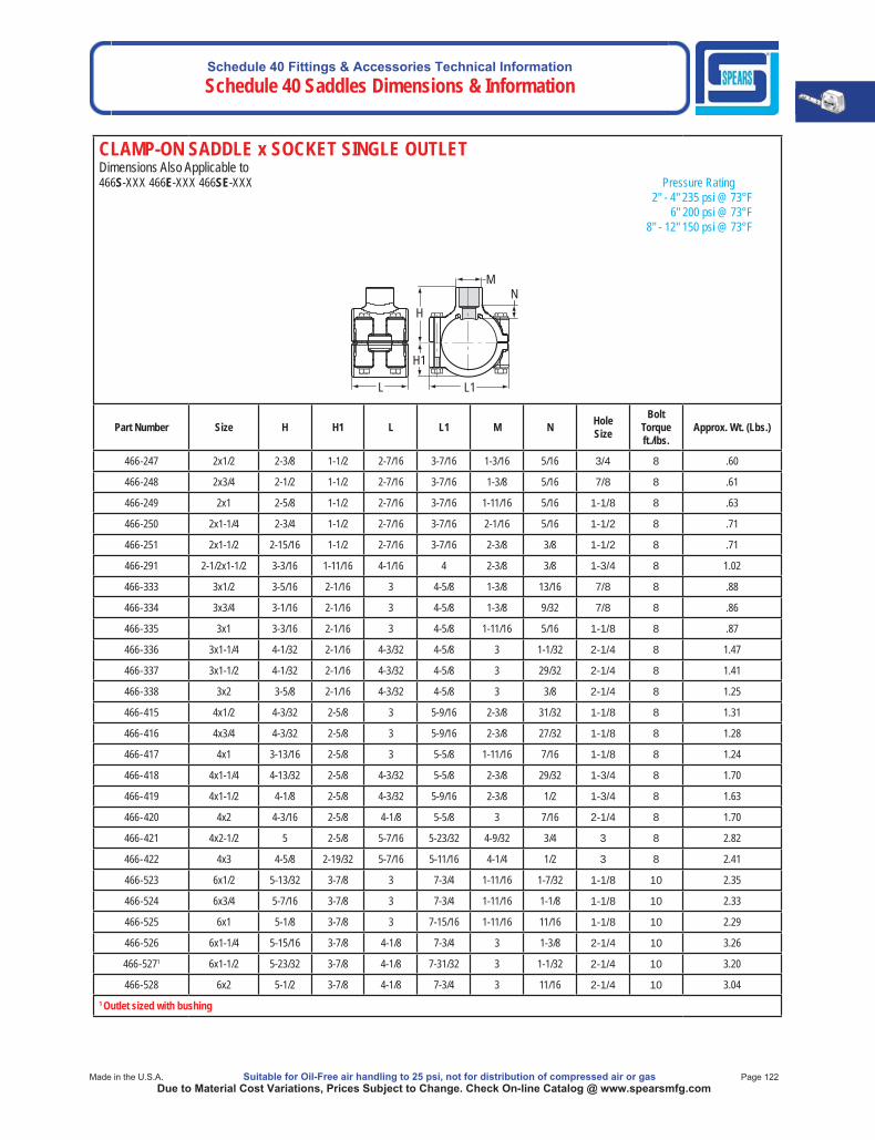
Schedule 40 Fittings & Accessories Technical InformationSchedule 40 Saddles Dimensions & Information
Made in the U.S.A. Suitable for Oil-Free air handling to 25 psi, not for distribution of compressed air or gas Page 122Due to Material Cost Variations, Prices Subject to Change. Check On-line Catalog @ www.spearsmfg.com
CLAMP-ON SADDLE x SOCKET SINGLE OUTLET Dimensions Also Applicable to466S-XXX 466E-XXX 466SE-XXX Pressure Rating 2" - 4" 235 psi @ 73°F 6" 200 psi @ 73°F 8" - 12" 150 psi @ 73°F
L L1
H
H1
M N
Part Number Size H H1 L L1 M N HoleSize
BoltTorqueft./lbs.
Approx. Wt. (Lbs.)
466-247 2x1/2 2-3/8 1-1/2 2-7/16 3-7/16 1-3/16 5/16 3/4 8 .60
466-248 2x3/4 2-1/2 1-1/2 2-7/16 3-7/16 1-3/8 5/16 7/8 8 .61
466-249 2x1 2-5/8 1-1/2 2-7/16 3-7/16 1-11/16 5/16 1-1/8 8 .63
466-250 2x1-1/4 2-3/4 1-1/2 2-7/16 3-7/16 2-1/16 5/16 1-1/2 8 .71
466-251 2x1-1/2 2-15/16 1-1/2 2-7/16 3-7/16 2-3/8 3/8 1-1/2 8 .71
466-291 2-1/2x1-1/2 3-3/16 1-11/16 4-1/16 4 2-3/8 3/8 1-3/4 8 1.02
466-333 3x1/2 3-5/16 2-1/16 3 4-5/8 1-3/8 13/16 7/8 8 .88
466-334 3x3/4 3-1/16 2-1/16 3 4-5/8 1-3/8 9/32 7/8 8 .86
466-335 3x1 3-3/16 2-1/16 3 4-5/8 1-11/16 5/16 1-1/8 8 .87
466-336 3x1-1/4 4-1/32 2-1/16 4-3/32 4-5/8 3 1-1/32 2-1/4 8 1.47
466-337 3x1-1/2 4-1/32 2-1/16 4-3/32 4-5/8 3 29/32 2-1/4 8 1.41
466-338 3x2 3-5/8 2-1/16 4-3/32 4-5/8 3 3/8 2-1/4 8 1.25
466-415 4x1/2 4-3/32 2-5/8 3 5-9/16 2-3/8 31/32 1-1/8 8 1.31
466-416 4x3/4 4-3/32 2-5/8 3 5-9/16 2-3/8 27/32 1-1/8 8 1.28
466-417 4x1 3-13/16 2-5/8 3 5-5/8 1-11/16 7/16 1-1/8 8 1.24
466-418 4x1-1/4 4-13/32 2-5/8 4-3/32 5-5/8 2-3/8 29/32 1-3/4 8 1.70
466-419 4x1-1/2 4-1/8 2-5/8 4-3/32 5-9/16 2-3/8 1/2 1-3/4 8 1.63
466-420 4x2 4-3/16 2-5/8 4-1/8 5-5/8 3 7/16 2-1/4 8 1.70
466-421 4x2-1/2 5 2-5/8 5-7/16 5-23/32 4-9/32 3/4 3 8 2.82
466-422 4x3 4-5/8 2-19/32 5-7/16 5-11/16 4-1/4 1/2 3 8 2.41
466-523 6x1/2 5-13/32 3-7/8 3 7-3/4 1-11/16 1-7/32 1-1/8 10 2.35
466-524 6x3/4 5-7/16 3-7/8 3 7-3/4 1-11/16 1-1/8 1-1/8 10 2.33
466-525 6x1 5-1/8 3-7/8 3 7-15/16 1-11/16 11/16 1-1/8 10 2.29
466-526 6x1-1/4 5-15/16 3-7/8 4-1/8 7-3/4 3 1-3/8 2-1/4 10 3.26
466-5271 6x1-1/2 5-23/32 3-7/8 4-1/8 7-31/32 3 1-1/32 2-1/4 10 3.20
466-528 6x2 5-1/2 3-7/8 4-1/8 7-3/4 3 11/16 2-1/4 10 3.041 Outlet sized with bushing
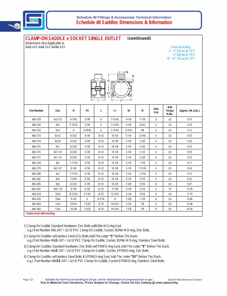
Schedule 40 Fittings & Accessories Technical Information Schedule 40 Saddles Dimensions & Information
Page 123 Suitable for Oil-Free air handling to 25 psi, not for distribution of compressed air or gas Spears® Manufacturing CompanyDue to Material Cost Variations, Prices Subject to Change. Check On-line Catalog @ www.spearsmfg
1) Clamp-On Saddle Standard Hardware: Zinc Bolts w/BUNA-N O-ring Seale.g.) Part Number 466-247 = 2x1/2 PVC Clamp On Saddle, Socket, BUNA-N O-ring, Zinc Bolts.
2) Clamp-On Saddles w/Stainless Steel (SS) Bolts,Add The Letter “S” Before The Dash.e.g.) Part Number 466S-247 = 2x1/2 PVC Clamp On Saddle, Socket, BUNA-N O-ring, Stainless Steel Bolts.
3) Clamp-On Saddles Standard Hardware: Zinc Bolts w/EPDM O-ring Seal, Add The Letter “E” Before The Dash.e.g.) Part Number 466E-247 = 2x1/2 PVC Clamp-On Saddle, Socket, EPDM O-ring, Zinc Bolts.
4) Clamp-On Saddles w/Stainless Steel Bolts & EPDM O-ring Seal, Add The Letter “SE” Before The Dash.e.g.) Part Number 466SE-247 = 2x1/2 PVC Clamp On Saddle, Socket EPDM O-ring, Stainless Steel Bolts.
CLAMP-ON SADDLE x SOCKET SINGLE OUTLET Dimensions Also Applicable to466S-XXX 466E-XXX 466SE-XXX Pressure Rating 2" - 4" 235 psi @ 73°F 6" 200 psi @ 73°F 8" - 12" 150 psi @ 73°F
L L1
H
H1
M N
Part Number Size H H1 L L1 M N HoleSize
BoltTorqueft./lbs.
Approx. Wt. (Lbs.)
466-529 6x2-1/2 6-7/16 3-7/8 6 7-15/16 4-1/4 1-1/8 3 10 4.75
466-530 6x3 5-15/16 3-7/8 6 7-15/16 4-1/4 25/32 3 10 4.33
466-532 6x4 6 3-29/32 6 7-15/16 5-3/16 5/8 4 10 5.12
466-573 8x1/2 8-3/32 4-7/8 8-1/2 10-1/8 5-1/4 2-3/16 4 10 9.35
466-574 8x3/4 8-3/32 4-7/8 8-1/2 10-1/8 5-1/4 2-3/4 4 10 9.36
466-575 8x1 8-3/32 4-7/8 8-1/2 10-1/8 5-1/4 2-5/8 4 10 9.37
466-576 8x1-1/4 8-3/32 4-7/8 8-1/2 10-1/8 5-1/4 2-1/2 4 10 9.39
466-577 8x1-1/2 8-3/32 4-7/8 8-1/2 10-1/8 5-1/4 2-3/8 4 10 9.32
466-578 8x2 7-11/16 4-7/8 8-1/2 10-1/8 5-1/4 1-7/8 4 10 9.17
466-579 8x2-1/2 8-1/8 4-7/8 8-1/2 10-1/8 5-1/4 1-11/16 4 10 9.24
466-580 8x3 7-11/16 4-7/8 8-1/2 10-1/8 5-1/4 1-7/16 4 10 9.15
466-582 8x4 7-5/16 4-7/8 8-1/2 10-1/8 5-1/4 11/16 4 10 8.35
466-585 8x6 8-3/32 4-7/8 8-1/2 10-1/8 7-5/8 11/16 6 10 9.47
466-6201 10x1-1/2 8-7/8 6-1/8 8-1/2 11-7/8 5-1/4 3-1/4 4 10 12.78
466-624 10x4 8-15/32 6-1/32 8-1/2 12-5/16 5-1/4 13/16 4 10 11.79
466-626 10x6 9-1/8 6 8-7/16 12 7-5/8 1-1/8 6 10 12.86
466-664 12x4 9-9/16 7-5/32 8-1/2 14-5/16 5-1/4 7/8 4 10 15.48
466-666 12x6 10-3/8 7-5/32 8-1/2 14-5/16 7-5/8 7/8 6 10 16.30 1Outlet sized with bushing
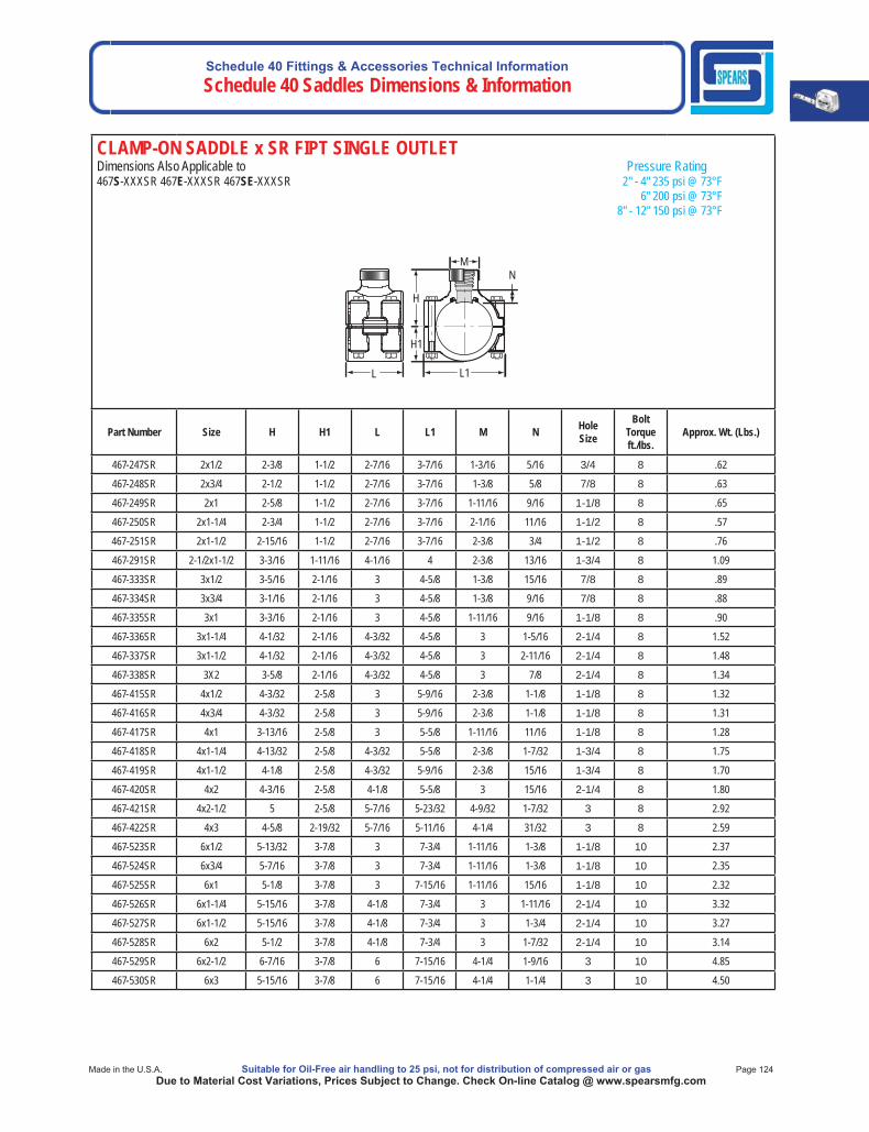
Schedule 40 Fittings & Accessories Technical InformationSchedule 40 Saddles Dimensions & Information
Made in the U.S.A. Suitable for Oil-Free air handling to 25 psi, not for distribution of compressed air or gas Page 124Due to Material Cost Variations, Prices Subject to Change. Check On-line Catalog @ www.spearsmfg.com
CLAMP-ON SADDLE x SR FIPT SINGLE OUTLET Dimensions Also Applicable to Pressure Rating467S-XXXSR 467E-XXXSR 467SE-XXXSR 2" - 4" 235 psi @ 73°F 6" 200 psi @ 73°F 8" - 12" 150 psi @ 73°F
N
L
M
L1
H
H1
Part Number Size H H1 L L1 M N HoleSize
BoltTorqueft./lbs.
Approx. Wt. (Lbs.)
467-247SR 2x1/2 2-3/8 1-1/2 2-7/16 3-7/16 1-3/16 5/16 3/4 8 .62
467-248SR 2x3/4 2-1/2 1-1/2 2-7/16 3-7/16 1-3/8 5/8 7/8 8 .63
467-249SR 2x1 2-5/8 1-1/2 2-7/16 3-7/16 1-11/16 9/16 1-1/8 8 .65
467-250SR 2x1-1/4 2-3/4 1-1/2 2-7/16 3-7/16 2-1/16 11/16 1-1/2 8 .57
467-251SR 2x1-1/2 2-15/16 1-1/2 2-7/16 3-7/16 2-3/8 3/4 1-1/2 8 .76
467-291SR 2-1/2x1-1/2 3-3/16 1-11/16 4-1/16 4 2-3/8 13/16 1-3/4 8 1.09
467-333SR 3x1/2 3-5/16 2-1/16 3 4-5/8 1-3/8 15/16 7/8 8 .89
467-334SR 3x3/4 3-1/16 2-1/16 3 4-5/8 1-3/8 9/16 7/8 8 .88
467-335SR 3x1 3-3/16 2-1/16 3 4-5/8 1-11/16 9/16 1-1/8 8 .90
467-336SR 3x1-1/4 4-1/32 2-1/16 4-3/32 4-5/8 3 1-5/16 2-1/4 8 1.52
467-337SR 3x1-1/2 4-1/32 2-1/16 4-3/32 4-5/8 3 2-11/16 2-1/4 8 1.48
467-338SR 3X2 3-5/8 2-1/16 4-3/32 4-5/8 3 7/8 2-1/4 8 1.34
467-415SR 4x1/2 4-3/32 2-5/8 3 5-9/16 2-3/8 1-1/8 1-1/8 8 1.32
467-416SR 4x3/4 4-3/32 2-5/8 3 5-9/16 2-3/8 1-1/8 1-1/8 8 1.31
467-417SR 4x1 3-13/16 2-5/8 3 5-5/8 1-11/16 11/16 1-1/8 8 1.28
467-418SR 4x1-1/4 4-13/32 2-5/8 4-3/32 5-5/8 2-3/8 1-7/32 1-3/4 8 1.75
467-419SR 4x1-1/2 4-1/8 2-5/8 4-3/32 5-9/16 2-3/8 15/16 1-3/4 8 1.70
467-420SR 4x2 4-3/16 2-5/8 4-1/8 5-5/8 3 15/16 2-1/4 8 1.80
467-421SR 4x2-1/2 5 2-5/8 5-7/16 5-23/32 4-9/32 1-7/32 3 8 2.92
467-422SR 4x3 4-5/8 2-19/32 5-7/16 5-11/16 4-1/4 31/32 3 8 2.59
467-523SR 6x1/2 5-13/32 3-7/8 3 7-3/4 1-11/16 1-3/8 1-1/8 10 2.37
467-524SR 6x3/4 5-7/16 3-7/8 3 7-3/4 1-11/16 1-3/8 1-1/8 10 2.35
467-525SR 6x1 5-1/8 3-7/8 3 7-15/16 1-11/16 15/16 1-1/8 10 2.32
467-526SR 6x1-1/4 5-15/16 3-7/8 4-1/8 7-3/4 3 1-11/16 2-1/4 10 3.32
467-527SR 6x1-1/2 5-15/16 3-7/8 4-1/8 7-3/4 3 1-3/4 2-1/4 10 3.27
467-528SR 6x2 5-1/2 3-7/8 4-1/8 7-3/4 3 1-7/32 2-1/4 10 3.14
467-529SR 6x2-1/2 6-7/16 3-7/8 6 7-15/16 4-1/4 1-9/16 3 10 4.85
467-530SR 6x3 5-15/16 3-7/8 6 7-15/16 4-1/4 1-1/4 3 10 4.50

Schedule 40 Fittings & Accessories Technical Information Schedule 40 Saddles Dimensions & Information
Page 125 Suitable for Oil-Free air handling to 25 psi, not for distribution of compressed air or gas Spears® Manufacturing CompanyDue to Material Cost Variations, Prices Subject to Change. Check On-line Catalog @ www.spearsmfg.com
CLAMP-ON SADDLE x SR FIPT SINGLE OUTLET Dimensions Also Applicable to Pressure Rating467S-XXXSR 467E-XXXSR 467SE-XXXSR 2" - 4" 235 psi @ 73°F 6" 200 psi @ 73°F 8" - 12" 150 psi @ 73°F
N
L
M
L1
H
H1
Part Number Size H H1 L L1 M N HoleSize
BoltTorqueft./lbs.
Approx. Wt. (Lbs.)
467-532SR 6x4 6 3-29/32 6 7-15/16 5-3/16 1-3/8 4 10 5.48
467-573SR 8x1/2 8-3/32 4-7/8 8-1/2 10-1/8 5-1/4 3 4 10 9.42
467-574SR 8x3/4 8-3/32 4-7/8 8-1/2 10-1/8 5-1/4 3 4 10 9.43
467-575SR 8x1 8-3/32 4-7/8 8-1/2 10-1/8 5-1/4 2-13/16 4 10 9.43
467-576SR 8x1-1/4 8-3/32 4-7/8 8-1/2 10-1/8 5-1/4 2-3/4 4 10 9.56
467-577SR 8x1-1/2 8-3/32 4-7/8 8-1/2 10-1/8 5-1/4 2-3/4 4 10 9.39
467-578SR 8x2 7-11/16 4-7/8 8-1/2 10-1/8 5-1/4 2-3/8 4 10 9.21
467-579SR 8x2-1/2 8-1/8 4-7/8 8-1/2 10-1/8 5-1/4 2-1/2 4 10 9.15
467-580SR 8x3 7-11/16 4-7/8 8-1/2 10-1/8 5-1/4 1-15/16 4 10 10.06
467-582SR 8x4 7-5/16 4-7/8 8-1/2 10-1/8 5-1/4 1-1/2 4 10 8.51
467-585SR 8x6 8-3/32 4-7/8 8-1/2 10-1/8 7-5/8 2-3/32 6 10 10.20
467-624SR 10x4 8-15/32 6-1/32 8-1/2 12-5/16 5-1/4 2-3/16 4 10 12.09
467-626SR 10x6 9-9/32 6-1/32 8-1/2 12-5/16 7-5/8 3-3/16 6 10 13.45
467-664SR 12x4 9-9/16 7-5/32 8-1/2 14-5/16 5-1/4 1-5/8 4 10 15.69
467-666SR 12x6 10-3/8 7-5/32 8-1/2 14-5/16 7-5/8 2-1/4 6 10 16.92
1) Clamp-On Saddle Standard Hardware: Zinc Bolts w/BUNA-N O-ring Seale.g.) Part Number 467-247SR = 2x1/2 PVC Clamp On Saddle, Socket, BUNA-N O-ring, Zinc Bolts.
2) Clamp-On Saddles w/Stainless Steel (SS) Bolts,Add The Letter “S” Before The Dash.e.g.) Part Number 467S-247SR = 2x1/2 PVC Clamp On Saddle, Socket, BUNA-N O-ring, Stainless Steel Bolts.
3) Clamp-On Saddles Standard Hardware: Zinc Bolts w/EPDM O-ring Seal, Add The Letter “E” Before The Dash.e.g.) Part Number 467E-247SR = 2x1/2 PVC Clamp-On Saddle, Socket, EPDM O-ring, Zinc Bolts.
4) Clamp-On Saddles w/Stainless Steel Bolts & EPDM O-ring Seal, Add The Letter “SE” Before The Dash.e.g.) Part Number 467SE-247SR = 2x1/2 PVC Clamp On Saddle, Socket EPDM O-ring, Stainless Steel Bolts.

Schedule 40 Fittings & Accessories Technical InformationSchedule 40 Saddles Dimensions & Information
Made in the U.S.A. Suitable for Oil-Free air handling to 25 psi, not for distribution of compressed air or gas Page 126Due to Material Cost Variations, Prices Subject to Change. Check On-line Catalog @ www.spearsmfg.com
CLAMP-ON SADDLE x SOCKET DOUBLE OUTLETDimensions Also Applicable to Pressure Rating468S-Xxx 468E-Xxx 468SE-Xxx 2" - 4" 235 psi @ 73°F 6" 200 psi @ 73°F 8" - 12" 150 psi @ 73°F
M N
H
L1 L
Part Number Size H L L1 M N HoleSize
BoltTorqueft./lbs.
Approx. Wt. (Lbs.)
468-247 2x1/2 2-3/8 2-7/16 3-7/16 1-3/16 5/16 3/4 8 .63
468-248 2x3/4 2-1/2 2-7/16 3-7/16 1-3/8 5/16 7/8 8 .65
468-249 2x1 2-5/8 2-7/16 3-7/16 1-11/16 5/16 1-1/8 8 .68
468-250 2x1-1/4 2-3/4 2-7/16 3-7/16 2-1/16 5/16 1-1/2 8 .73
468-251 2x1-1/2 2-15/16 2-7/16 3-7/16 2-3/8 3/8 1-1/2 8 .85
468-291 2-1/2x1-1/2 3-3/16 4-1/16 4 2-3/8 3/8 1-3/4 8 1.15
468-333 3x1/2 3-5/16 3 4-5/8 1-3/8 13/16 7/8 8 .93
468-334 3x3/4 3-1/16 3 4-5/8 1-3/8 9/32 7/8 8 .89
468-335 3x1 3-3/16 3 4-5/8 1-11/16 5/16 1-1/8 8 .91
468-336 3x1-1/4 4-1/32 4-3/32 4-5/8 3 1-1/32 2-1/4 8 1.93
468-337 3x1-1/2 4-1/32 4-3/32 4-5/8 3 29/32 2-1/4 8 1.80
468-338 3x2 3-5/8 4-3/32 4-5/8 3 3/8 2-1/4 8 1.48
468-415 4x1/2 4-3/32 3 5-9/16 2-3/8 31/32 1-1/8 8 1.43
468-416 4x3/4 4-3/32 3 5-9/16 2-3/8 27/32 1-1/8 8 1.37
468-417 4x1 3-13/16 3 5-5/8 1-11/16 7/16 1-1/8 8 1.30
468-418 4x1-1/4 4-13/32 4-3/32 5-5/8 2-3/8 29/32 1-3/4 8 1.91
468-419 4x1-1/2 4-1/8 4-3/32 5-9/16 2-3/8 1/2 1-3/4 8 1.76
468-420 4x2 4-3/16 4-1/8 5-5/8 3 7/16 2-1/4 8 1.91
468-421 4x2-1/2 5 5-7/16 5-23/32 4-9/32 3/4 3 8 3.77
468-422 4x3 4-5/8 5-7/16 5-11/16 4-1/4 1/2 3 8 2.95
468-523 6x1/2 5-13/32 3 7-3/4 1-11/16 1-7/32 1-1/8 10 2.48
468-524 6x3/4 5-7/16 3 7-3/4 1-11/16 1-1/8 1-1/8 10 2.44
468-525 6x1 5-1/8 3 7-15/16 1-11/16 11/16 1-1/8 10 2.35
468-526 6x1-1/4 5-15/16 4-1/8 7-3/4 3 1-3/8 2-1/4 10 3.70
468-527 6x1-1/2 5-15/16 4-1/8 7-3/4 3 1-1/4 2-1/4 10 3.57
468-528 6x2 5-1/2 4-1/8 7-3/4 3 11/16 2-1/4 10 3.26
468-529 6x2-1/2 6-7/16 6 7-15/16 4-1/4 1-1/8 3 10 5.61
468-530 6x3 5-15/16 6 7-15/16 4-1/4 25/32 3 10 4.78
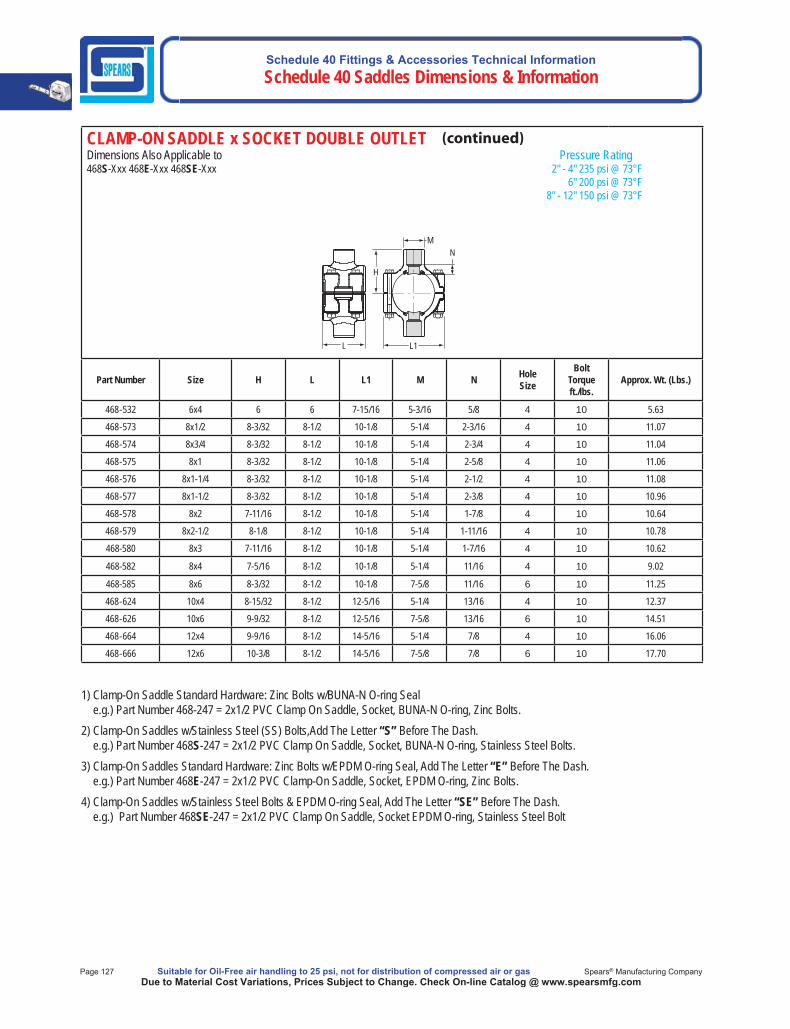
Schedule 40 Fittings & Accessories Technical Information Schedule 40 Saddles Dimensions & Information
Page 127 Suitable for Oil-Free air handling to 25 psi, not for distribution of compressed air or gas Spears® Manufacturing CompanyDue to Material Cost Variations, Prices Subject to Change. Check On-line Catalog @ www.spearsmfg.com
CLAMP-ON SADDLE x SOCKET DOUBLE OUTLETDimensions Also Applicable to Pressure Rating468S-Xxx 468E-Xxx 468SE-Xxx 2" - 4" 235 psi @ 73°F 6" 200 psi @ 73°F 8" - 12" 150 psi @ 73°F
M N
H
L1 L
Part Number Size H L L1 M N HoleSize
BoltTorqueft./lbs.
Approx. Wt. (Lbs.)
468-532 6x4 6 6 7-15/16 5-3/16 5/8 4 10 5.63
468-573 8x1/2 8-3/32 8-1/2 10-1/8 5-1/4 2-3/16 4 10 11.07
468-574 8x3/4 8-3/32 8-1/2 10-1/8 5-1/4 2-3/4 4 10 11.04
468-575 8x1 8-3/32 8-1/2 10-1/8 5-1/4 2-5/8 4 10 11.06
468-576 8x1-1/4 8-3/32 8-1/2 10-1/8 5-1/4 2-1/2 4 10 11.08
468-577 8x1-1/2 8-3/32 8-1/2 10-1/8 5-1/4 2-3/8 4 10 10.96
468-578 8x2 7-11/16 8-1/2 10-1/8 5-1/4 1-7/8 4 10 10.64
468-579 8x2-1/2 8-1/8 8-1/2 10-1/8 5-1/4 1-11/16 4 10 10.78
468-580 8x3 7-11/16 8-1/2 10-1/8 5-1/4 1-7/16 4 10 10.62
468-582 8x4 7-5/16 8-1/2 10-1/8 5-1/4 11/16 4 10 9.02
468-585 8x6 8-3/32 8-1/2 10-1/8 7-5/8 11/16 6 10 11.25
468-624 10x4 8-15/32 8-1/2 12-5/16 5-1/4 13/16 4 10 12.37
468-626 10x6 9-9/32 8-1/2 12-5/16 7-5/8 13/16 6 10 14.51
468-664 12x4 9-9/16 8-1/2 14-5/16 5-1/4 7/8 4 10 16.06
468-666 12x6 10-3/8 8-1/2 14-5/16 7-5/8 7/8 6 10 17.70
1) Clamp-On Saddle Standard Hardware: Zinc Bolts w/BUNA-N O-ring Seale.g.) Part Number 468-247 = 2x1/2 PVC Clamp On Saddle, Socket, BUNA-N O-ring, Zinc Bolts.
2) Clamp-On Saddles w/Stainless Steel (SS) Bolts,Add The Letter “S” Before The Dash.e.g.) Part Number 468S-247 = 2x1/2 PVC Clamp On Saddle, Socket, BUNA-N O-ring, Stainless Steel Bolts.
3) Clamp-On Saddles Standard Hardware: Zinc Bolts w/EPDM O-ring Seal, Add The Letter “E” Before The Dash.e.g.) Part Number 468E-247 = 2x1/2 PVC Clamp-On Saddle, Socket, EPDM O-ring, Zinc Bolts.
4) Clamp-On Saddles w/Stainless Steel Bolts & EPDM O-ring Seal, Add The Letter “SE” Before The Dash.e.g.) Part Number 468SE-247 = 2x1/2 PVC Clamp On Saddle, Socket EPDM O-ring, Stainless Steel Bolt

Schedule 40 Fittings & Accessories Technical InformationSchedule 40 Saddles Dimensions & Information
Made in the U.S.A. Suitable for Oil-Free air handling to 25 psi, not for distribution of compressed air or gas Page 128Due to Material Cost Variations, Prices Subject to Change. Check On-line Catalog @ www.spearsmfg.com
CLAMP-ON SADDLE x SR FIPT DOUBLE OUTLETDimensions Also Applicable to Pressure Rating469S-XXXSR 469E-XXXSR 469SE-XXXSR 2" - 4" 235 psi @ 73°F 6" 200 psi @ 73°F 8" - 12" 150 psi @ 73°F
N M
H
L1 L
Part Number Size H L L1 M N HoleSize
BoltTorqueft./lbs.
Approx. Wt. (Lbs.)
469-247SR 2x1/2 2-3/8 2-7/16 3-7/16 1-3/16 5/16 3/4 8 .66
469-248SR 2x3/4 2-1/2 2-7/16 3-7/16 1-3/8 5/16 7/8 8 .67
469-249SR 2x1 2-5/8 2-7/16 3-7/16 1-11/16 5/16 1-1/8 8 .73
469-250SR 2x1-1/4 2-3/4 2-7/16 3-7/16 2-1/16 5/16 1-1/2 8 .79
469-251SR 2x1-1/2 2-15/16 2-7/16 3-7/16 2-3/8 3/8 1-1/2 8 .93
469-291SR 2-1/2x1-1/2 3-3/16 4-1/16 4 2-3/8 3/8 1-3/4 8 1.30
469-333SR 3x1/2 3-5/16 3 4-5/8 1-3/8 13/16 7/8 8 .96
469-334SR 3x3/4 3-1/16 3 4-5/8 1-3/8 9/32 7/8 8 .93
469-335SR 3x1 3-3/16 3 4-5/8 1-11/16 5/16 1-1/8 8 .98
469-336SR 3x1-1/4 4-1/32 4-3/32 4-5/8 3 1-1/32 2-1/4 8 2.04
469-337SR 3x1-1/2 4-1/32 4-3/32 4-5/8 3 2-11/16 2-1/4 8 1.94
469-338SR 3x2 3-5/8 4-3/32 4-5/8 3 3/8 2-1/4 8 1.67
469-415SR 4x1/2 4-3/32 3 5-9/16 2-3/8 31/32 1-1/8 8 1.46
469-416SR 4x3/4 4-3/32 3 5-9/16 2-3/8 27/32 1-1/8 8 1.44
469-417SR 4x1 3-13/16 3 5-5/8 1-11/16 7/16 1-1/8 8 1.37
469-418SR 4x1-1/4 4-13/32 4-3/32 5-5/8 2-3/8 29/32 1-3/4 8 2.00
469-419SR 4x1-1/2 4-1/8 4-3/32 5-9/16 2-3/8 1/2 1-3/4 8 1.89
469-420SR 4x2 4-3/16 4-1/8 5-5/8 3 7/16 2-1/4 8 2.10
469-421SR 4x2-1/2 5 5-7/16 5-23/32 4-9/32 3/4 3 8 3.98
469-422SR 4x3 4-5/8 5-7/16 5-11/16 4-1/4 1/2 3 8 3.31
469-523SR 6x1/2 5-13/32 3 7-3/4 1-11/16 1-7/32 1-1/8 10 2.51
469-524SR 6x3/4 5-7/16 3 7-3/4 1-11/16 1-1/8 1-1/8 10 2.48
469-525SR 6x1 5-1/8 3 7-15/16 1-11/16 11/16 1-1/8 10 2.42
469-526SR 6x1-1/4 5-15/16 4-1/8 7-3/4 3 1-3/8 2-1/4 10 3.81
469-527SR 6x1-1/2 5-15/16 4-1/8 7-3/4 3 1-1/4 2-1/4 10 3.71
469-528SR 6x2 5-1/2 4-1/8 7-3/4 3 11/16 2-1/4 10 3.45
469-529SR 6x2-1/2 6-7/16 6 7-15/16 4-1/4 1-1/8 3 10 5.82
469-530SR 6x3 5-15/16 6 7-15/16 4-1/4 25/32 3 10 5.12
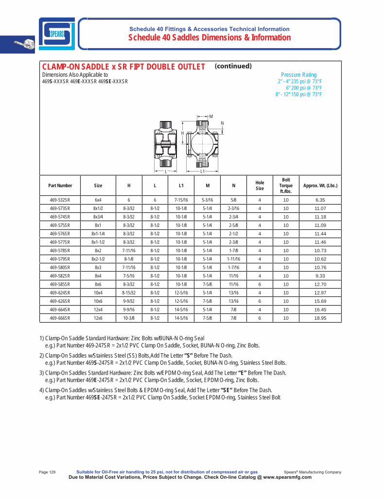
Schedule 40 Fittings & Accessories Technical Information Schedule 40 Saddles Dimensions & Information
Page 129 Suitable for Oil-Free air handling to 25 psi, not for distribution of compressed air or gas Spears® Manufacturing CompanyDue to Material Cost Variations, Prices Subject to Change. Check On-line Catalog @ www.spearsmfg.com
CLAMP-ON SADDLE x SR FIPT DOUBLE OUTLETDimensions Also Applicable to Pressure Rating469S-XXXSR 469E-XXXSR 469SE-XXXSR 2" - 4" 235 psi @ 73°F 6" 200 psi @ 73°F 8" - 12" 150 psi @ 73°F
N M
H
L1 L
Part Number Size H L L1 M N HoleSize
BoltTorqueft./lbs.
Approx. Wt. (Lbs.)
469-532SR 6x4 6 6 7-15/16 5-3/16 5/8 4 10 6.35
469-573SR 8x1/2 8-3/32 8-1/2 10-1/8 5-1/4 2-3/16 4 10 11.07
469-574SR 8x3/4 8-3/32 8-1/2 10-1/8 5-1/4 2-3/4 4 10 11.18
469-575SR 8x1 8-3/32 8-1/2 10-1/8 5-1/4 2-5/8 4 10 11.09
469-576SR 8x1-1/4 8-3/32 8-1/2 10-1/8 5-1/4 2-1/2 4 10 11.44
469-577SR 8x1-1/2 8-3/32 8-1/2 10-1/8 5-1/4 2-3/8 4 10 11.46
469-578SR 8x2 7-11/16 8-1/2 10-1/8 5-1/4 1-7/8 4 10 10.73
469-579SR 8x2-1/2 8-1/8 8-1/2 10-1/8 5-1/4 1-11/16 4 10 10.62
469-580SR 8x3 7-11/16 8-1/2 10-1/8 5-1/4 1-7/16 4 10 10.76
469-582SR 8x4 7-5/16 8-1/2 10-1/8 5-1/4 11/16 4 10 9.33
469-585SR 8x6 8-3/32 8-1/2 10-1/8 7-5/8 11/16 6 10 12.70
469-624SR 10x4 8-15/32 8-1/2 12-5/16 5-1/4 13/16 4 10 12.97
469-626SR 10x6 9-9/32 8-1/2 12-5/16 7-5/8 13/16 6 10 15.69
469-664SR 12x4 9-9/16 8-1/2 14-5/16 5-1/4 7/8 4 10 16.45
469-666SR 12x6 10-3/8 8-1/2 14-5/16 7-5/8 7/8 6 10 18.95
1) Clamp-On Saddle Standard Hardware: Zinc Bolts w/BUNA-N O-ring Seale.g.) Part Number 469-247SR = 2x1/2 PVC Clamp On Saddle, Socket, BUNA-N O-ring, Zinc Bolts.
2) Clamp-On Saddles w/Stainless Steel (SS) Bolts,Add The Letter “S” Before The Dash.e.g.) Part Number 469S-247SR = 2x1/2 PVC Clamp On Saddle, Socket, BUNA-N O-ring, Stainless Steel Bolts.
3) Clamp-On Saddles Standard Hardware: Zinc Bolts w/EPDM O-ring Seal, Add The Letter “E” Before The Dash.e.g.) Part Number 469E-247SR = 2x1/2 PVC Clamp-On Saddle, Socket, EPDM O-ring, Zinc Bolts.
4) Clamp-On Saddles w/Stainless Steel Bolts & EPDM O-ring Seal, Add The Letter “SE” Before The Dash.e.g.) Part Number 469SE-247SR = 2x1/2 PVC Clamp On Saddle, Socket EPDM O-ring, Stainless Steel Bolt
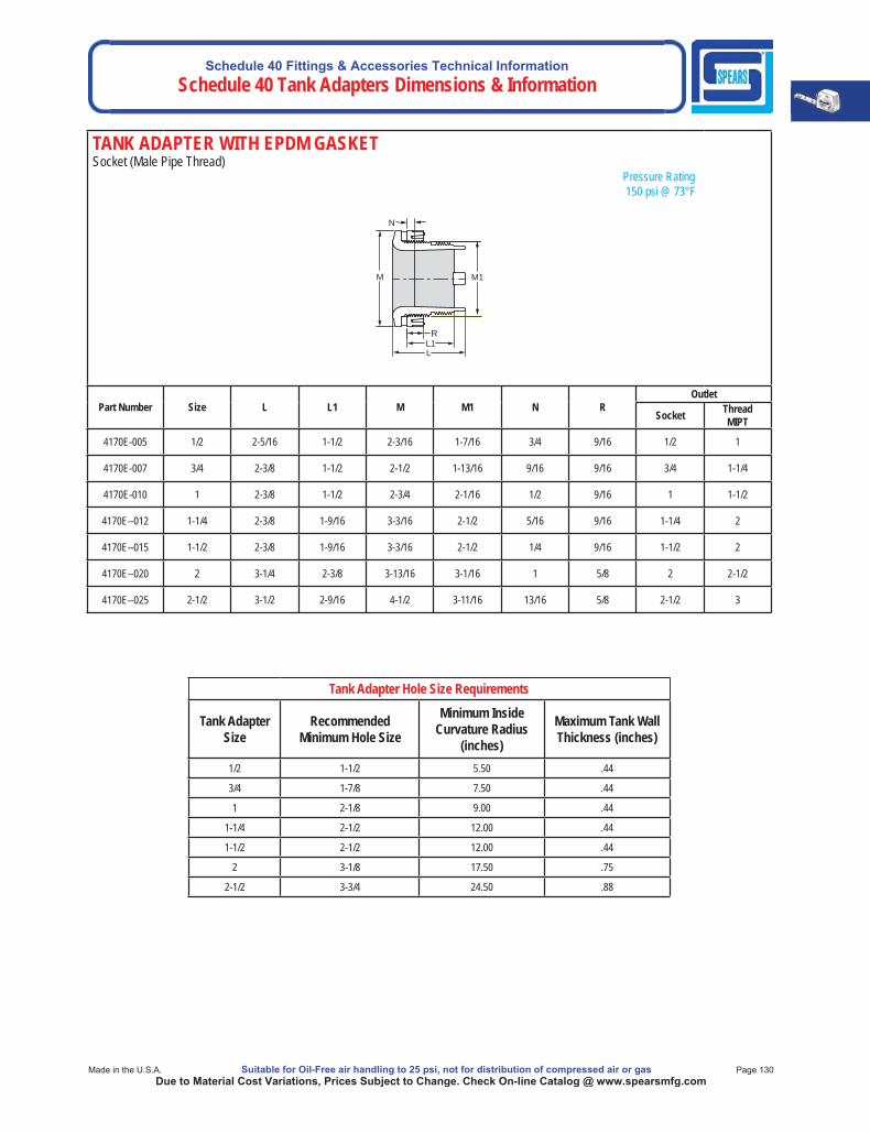
Schedule 40 Fittings & Accessories Technical InformationSchedule 40 Tank Adapters Dimensions & Information
Made in the U.S.A. Suitable for Oil-Free air handling to 25 psi, not for distribution of compressed air or gas Page 130Due to Material Cost Variations, Prices Subject to Change. Check On-line Catalog @ www.spearsmfg.com
TANK ADAPTER WITH EPDM GASKETSocket (Male Pipe Thread) Pressure Rating 150 psi @ 73°F
N
M
R
M1
L1L
Part Number Size L L1 M M1 N ROutlet
Socket ThreadMIPT
4170E-005 1/2 2-5/16 1-1/2 2-3/16 1-7/16 3/4 9/16 1/2 1
4170E-007 3/4 2-3/8 1-1/2 2-1/2 1-13/16 9/16 9/16 3/4 1-1/4
4170E-010 1 2-3/8 1-1/2 2-3/4 2-1/16 1/2 9/16 1 1-1/2
4170E--012 1-1/4 2-3/8 1-9/16 3-3/16 2-1/2 5/16 9/16 1-1/4 2
4170E--015 1-1/2 2-3/8 1-9/16 3-3/16 2-1/2 1/4 9/16 1-1/2 2
4170E--020 2 3-1/4 2-3/8 3-13/16 3-1/16 1 5/8 2 2-1/2
4170E--025 2-1/2 3-1/2 2-9/16 4-1/2 3-11/16 13/16 5/8 2-1/2 3
Tank Adapter Hole Size Requirements
Tank Adapter Size
RecommendedMinimum Hole Size
Minimum InsideCurvature Radius
(inches)
Maximum Tank Wall Thickness (inches)
1/2 1-1/2 5.50 .44
3/4 1-7/8 7.50 .44
1 2-1/8 9.00 .44
1-1/4 2-1/2 12.00 .44
1-1/2 2-1/2 12.00 .44
2 3-1/8 17.50 .75
2-1/2 3-3/4 24.50 .88
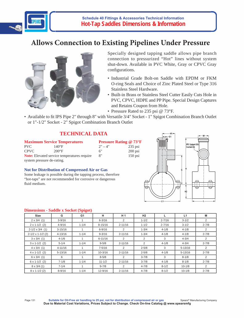
Schedule 40 Fittings & Accessories Technical Information
Hot-Tap Saddles Dimensions & Information
Page 131 Suitable for Oil-Free air handling to 25 psi, not for distribution of compressed air or gas Spears® Manufacturing CompanyDue to Material Cost Variations, Prices Subject to Change. Check On-line Catalog @ www.spearsmfg
Allows Connection to Existing Pipelines Under Pressure
• Industrial Grade Bolt-on Saddle with EPDM or FKMO-ring Seals and Choice of Zinc Plated Steel or Type 316Stainless Steel Hardware.
• Built-in Brass or Stainless Steel Cutter Easily Cuts Hole inPVC, CPVC, HDPE and PP Pipe. Special Design Captures and Retains Coupon from Hole.
• Pressure Rated to 235 psi @ 73°F.• Available to fi t IPS Pipe 2" through 8" with Versatile 3/4" Socket - 1" Spigot Combination Branch Outlet
or 1"-1/2" Socket - 2" Spigot Combination Branch Outlet
Specially designed tapping saddle allows pipe branchconnection to pressurized “Hot” lines without systemshut-down. Available in PVC White, Gray or CPVC Gray confi gurations.
TECHNICAL DATAMaximum Service TemperaturesPVC 140°FCPVC 200°FNote: Elevated service temperatures require system pressure de-rating.
Not for Distribution of Compressed Air or GasSome leakage is possible during the tapping process, therefore “hot-taps” are not recommended for corrosive or dangerous fl uid medium.
Pressure Rating @ 73°F2" – 4" 235 psi6" 200 psi8" 150 psi
Dimensions - Saddle x Socket (Spigot)Size G G1 H H 1 H2 L L1 M
2 x 3/4 (1) 3-9/16 1 6-3/16 2 1-1/2 2-7/16 3-1/2 22 x 1-1/2 (2) 4-9/16 1-1/4 8-15/16 2-11/16 1-1/2 2-7/16 3-1/2 2-7/8
2-1/2 x 3/4 (1) 3-15/16 1 6-9/16 2 1-3/4 4-1/8 4-1/8 22-1/2 x 1-1/2 (2) 4-13/16 1-1/4 9-3/16 2-11/16 1-3/4 4-1/8 4-1/8 2-7/8
3 x 3/4 (1) 4-1/6 1 6-11/16 2 2 3 4-3/4 23 x 1-1/2 (2) 5-1/4 1-1/4 9-5/8 2-11/16 2 4-1/8 4-3/4 2-7/84 x 3/4 (1) 4-11/16 1 7-5/16 2 2-5/8 3 5-13/16 2
4 x 1-1/2 (2) 5-13/16 1-1/4 10-3/16 2-11/16 2-5/8 4-1/8 5-13/16 2-7/86 x 3/4 (1) 6 1 8-5/8 2 3-7/8 3 8-1/8 2
6 x 1-1/2 (2) 7-1/8 1-1/4 11-1/2 2-11/16 3-7/8 4-1/8 8-1/8 2-7/88 x 3/4 (1) 7-1/4 1 9-7/8 2 4-7/8 8-1/2 10-1/8 2
8 x 1-1/2 (2) 8-9/16 1-1/4 12-9/16 2-11/16 4-7/8 8-1/2 10-1/8 2-7/8
H1G1
G
L1
H
L
H2
M
IPS Spigot O.D.Socket I.D.
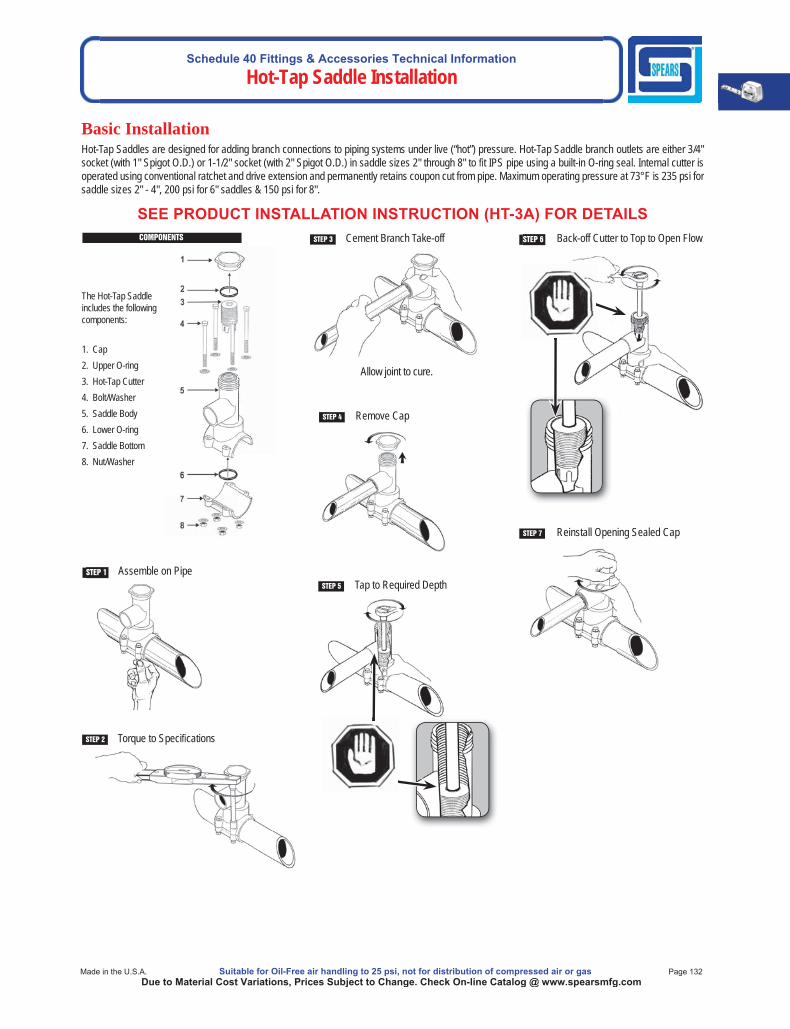
Schedule 40 Fittings & Accessories Technical Information
Hot-Tap Saddle Installation
Made in the U.S.A. Suitable for Oil-Free air handling to 25 psi, not for distribution of compressed air or gas Page 132Due to Material Cost Variations, Prices Subject to Change. Check On-line Catalog @ www.spearsmfg.com
Basic Installation
STEP 1 Assemble on Pipe
Hot-Tap Saddles are designed for adding branch connections to piping systems under live (“hot”) pressure. Hot-Tap Saddle branch outlets are either 3/4" socket (with 1" Spigot O.D.) or 1-1/2" socket (with 2" Spigot O.D.) in saddle sizes 2" through 8" to t IPS pipe using a built-in O-ring seal. Internal cutter is operated using conventional ratchet and drive extension and permanently retains coupon cut from pipe. Maximum operating pressure at 73°F is 235 psi forsaddle sizes 2" - 4", 200 psi for 6" saddles & 150 psi for 8".
STEP 2 Torque to Speci cations
Allow joint to cure.
STEP 3 Cement Branch Take-off
STEP 4 Remove Cap
STEP 5 Tap to Required Depth
STEP 6 Back-off Cutter to Top to Open Flow
STEP 7 Reinstall Opening Sealed Cap
SEE PRODUCT INSTALLATION INSTRUCTION (HT-3A) FOR DETAILS COMPONENTS
The Hot-Tap Saddle includes the following components:
1. Cap2. Upper O-ring3. Hot-Tap Cutter4. Bolt/Washer5. Saddle Body6. Lower O-ring7. Saddle Bottom8. Nut/Washer

Schedule 40 Fittings & Accessories Technical Information
Repair Fittings
Page 133 Suitable for Oil-Free air handling to 25 psi, not for distribution of compressed air or gas Spears® Manufacturing CompanyDue to Material Cost Variations, Prices Subject to Change. Check On-line Catalog @ www.spearsmfg.com
Schedule 40 Pipe Repair Fittings Allows Difficult Broken Pipe Repair To Be Made Easily
Pipe Extenders
Schedule 40 Repair Fittings
Pipe Extenders, Class 200
Class 200 Pipe
Inside Connectors
Extender Fittings
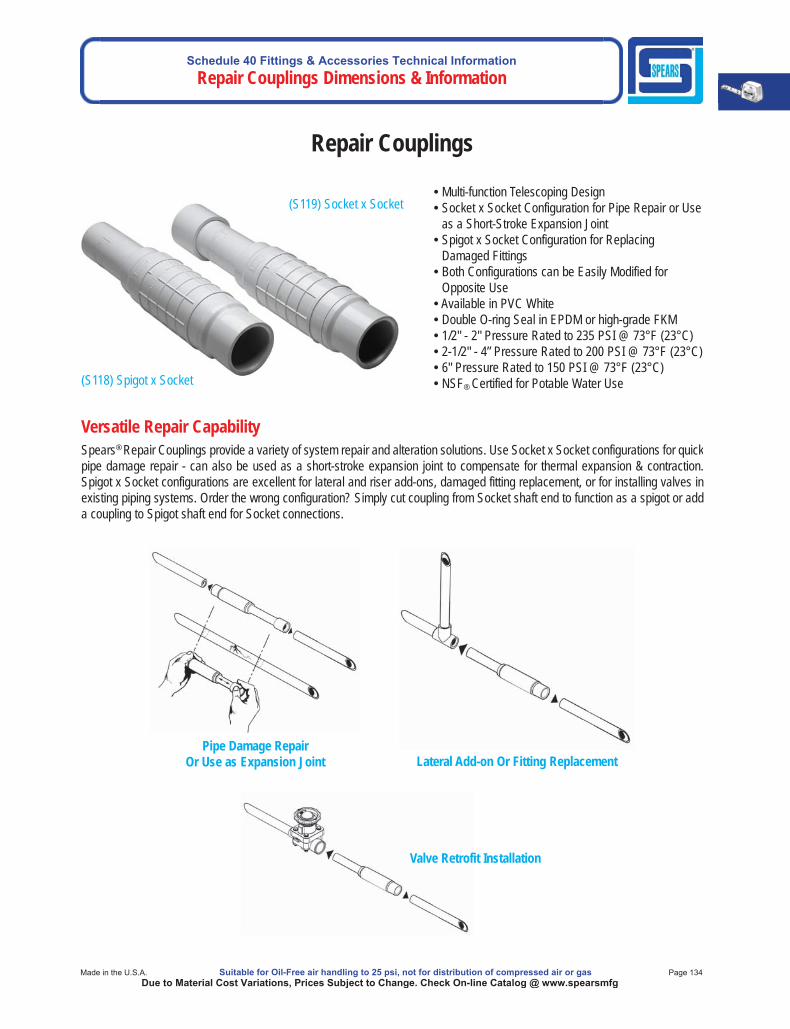
Schedule 40 Fittings & Accessories Technical InformationRepair Couplings Dimensions & Information
Made in the U.S.A. Suitable for Oil-Free air handling to 25 psi, not for distribution of compressed air or gas Page 134Due to Material Cost Variations, Prices Subject to Change. Check On-line Catalog @ www.spearsmfg
Versatile Repair CapabilitySpears® Repair Couplings provide a variety of system repair and alteration solutions. Use Socket x Socket configurations for quickpipe damage repair - can also be used as a short-stroke expansion joint to compensate for thermal expansion & contraction.Spigot x Socket configurations are excellent for lateral and riser add-ons, damaged fitting replacement, or for installing valves inexisting piping systems. Order the wrong configuration? Simply cut coupling from Socket shaft end to function as a spigot or adda coupling to Spigot shaft end for Socket connections.
Repair Couplings
• Multi-function Telescoping Design • Socket x Socket Configuration for Pipe Repair or Use
as a Short-Stroke Expansion Joint • Spigot x Socket Configuration for Replacing
Damaged Fittings • Both Configurations can be Easily Modified for
Opposite Use• Available in PVC White• Double O-ring Seal in EPDM or high-grade FKM • 1/2" - 2" Pressure Rated to 235 PSI @ 73°F (23°C) • 2-1/2" - 4” Pressure Rated to 200 PSI @ 73°F (23°C) • 6" Pressure Rated to 150 PSI @ 73°F (23°C) • NSF® Certified for Potable Water Use
Valve Retrofit Installation
Pipe Damage RepairOr Use as Expansion Joint Lateral Add-on Or Fitting Replacement
(S119) Socket x Socket
(S118) Spigot x Socket
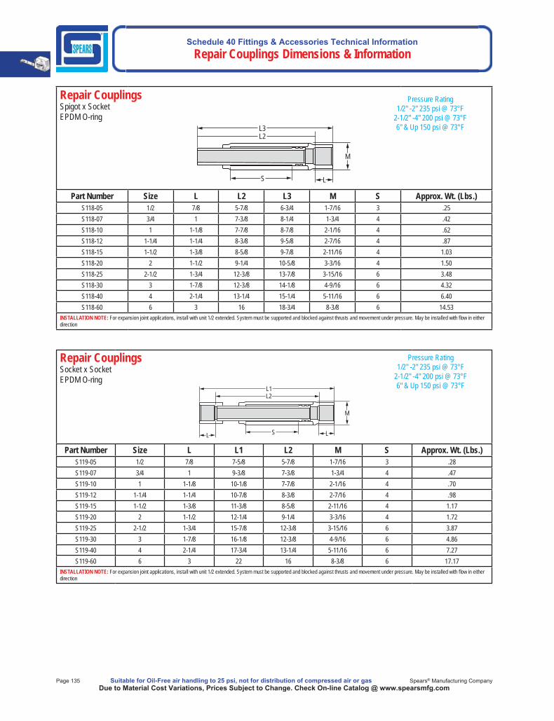
Schedule 40 Fittings & Accessories Technical Information Repair Couplings Dimensions & Information
Page 135 Suitable for Oil-Free air handling to 25 psi, not for distribution of compressed air or gas Spears® Manufacturing CompanyDue to Material Cost Variations, Prices Subject to Change. Check On-line Catalog @ www.spearsmfg.com
Repair Couplings Spigot x Socket EPDM O-ring
L3
M
LS
L2
Part Number Size L L2 L3 M S Approx. Wt. (Lbs.)S118-05 1/2 7/8 5-7/8 6-3/4 1-7/16 3 .25S118-07 3/4 1 7-3/8 8-1/4 1-3/4 4 .42S118-10 1 1-1/8 7-7/8 8-7/8 2-1/16 4 .62S118-12 1-1/4 1-1/4 8-3/8 9-5/8 2-7/16 4 .87S118-15 1-1/2 1-3/8 8-5/8 9-7/8 2-11/16 4 1.03S118-20 2 1-1/2 9-1/4 10-5/8 3-3/16 4 1.50S118-25 2-1/2 1-3/4 12-3/8 13-7/8 3-15/16 6 3.48S118-30 3 1-7/8 12-3/8 14-1/8 4-9/16 6 4.32S118-40 4 2-1/4 13-1/4 15-1/4 5-11/16 6 6.40S118-60 6 3 16 18-3/4 8-3/8 6 14.53
INSTALLATION NOTE: For expansion joint applications, install with unit 1/2 extended. System must be supported and blocked against thrusts and movement under pressure. May be installed with fl ow in either direction
Repair Couplings Socket x Socket EPDM O-ring
L1
M
LSL
L2
Part Number Size L L1 L2 M S Approx. Wt. (Lbs.)S119-05 1/2 7/8 7-5/8 5-7/8 1-7/16 3 .28S119-07 3/4 1 9-3/8 7-3/8 1-3/4 4 .47S119-10 1 1-1/8 10-1/8 7-7/8 2-1/16 4 .70S119-12 1-1/4 1-1/4 10-7/8 8-3/8 2-7/16 4 .98S119-15 1-1/2 1-3/8 11-3/8 8-5/8 2-11/16 4 1.17S119-20 2 1-1/2 12-1/4 9-1/4 3-3/16 4 1.72S119-25 2-1/2 1-3/4 15-7/8 12-3/8 3-15/16 6 3.87S119-30 3 1-7/8 16-1/8 12-3/8 4-9/16 6 4.86S119-40 4 2-1/4 17-3/4 13-1/4 5-11/16 6 7.27S119-60 6 3 22 16 8-3/8 6 17.17
INSTALLATION NOTE: For expansion joint applications, install with unit 1/2 extended. System must be supported and blocked against thrusts and movement under pressure. May be installed with fl ow in either direction
Pressure Rating1/2" -2" 235 psi @ 73°F
2-1/2" -4" 200 psi @ 73°F6" & Up 150 psi @ 73°F
Pressure Rating1/2" -2" 235 psi @ 73°F
2-1/2" -4" 200 psi @ 73°F6" & Up 150 psi @ 73°F
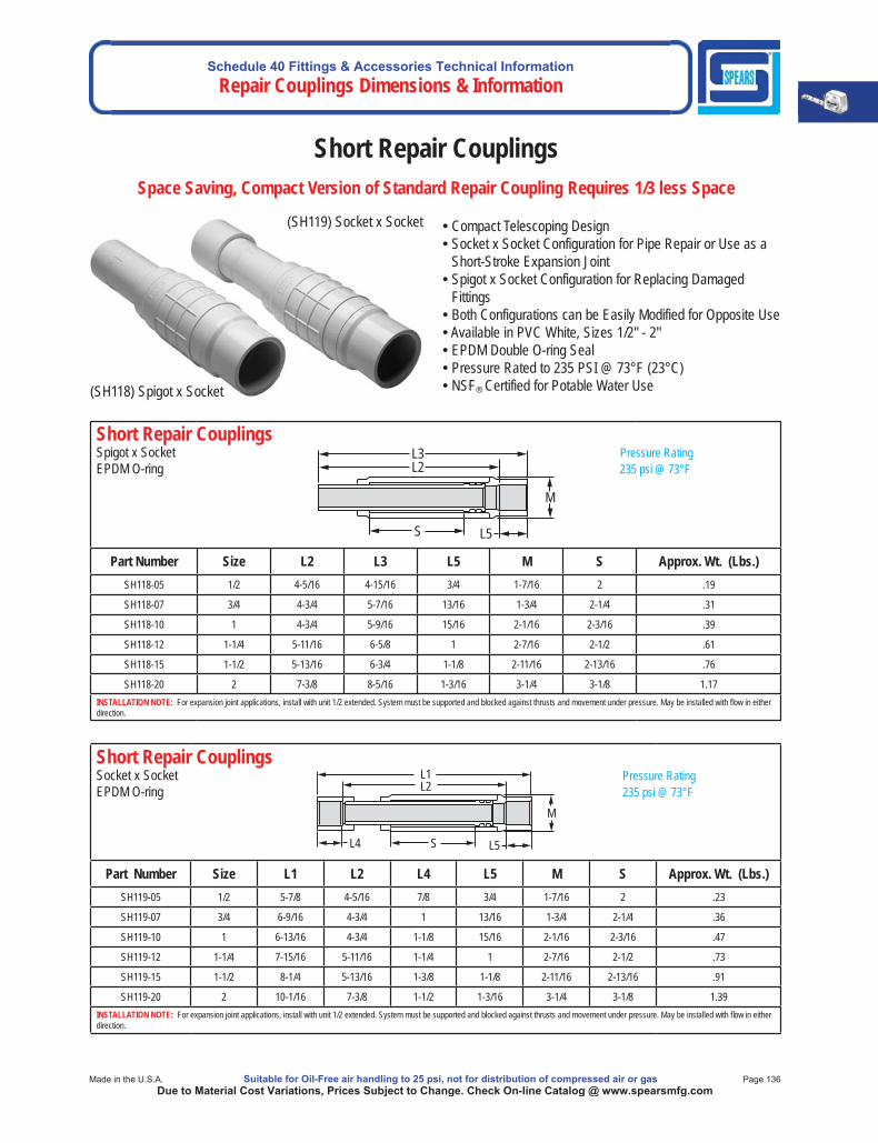
Schedule 40 Fittings & Accessories Technical InformationRepair Couplings Dimensions & Information
Made in the U.S.A. Suitable for Oil-Free air handling to 25 psi, not for distribution of compressed air or gas Page 136Due to Material Cost Variations, Prices Subject to Change. Check On-line Catalog @ www.spearsmfg.com
Short Repair CouplingsSpace Saving, Compact Version of Standard Repair Coupling Requires 1/3 less Space
Short Repair Couplings Spigot x Socket Pressure RatingEPDM O-ring 235 psi @ 73°F
Part Number Size L2 L3 L5 M S Approx. Wt. (Lbs.)SH118-05 1/2 4-5/16 4-15/16 3/4 1-7/16 2 .19
SH118-07 3/4 4-3/4 5-7/16 13/16 1-3/4 2-1/4 .31
SH118-10 1 4-3/4 5-9/16 15/16 2-1/16 2-3/16 .39
SH118-12 1-1/4 5-11/16 6-5/8 1 2-7/16 2-1/2 .61
SH118-15 1-1/2 5-13/16 6-3/4 1-1/8 2-11/16 2-13/16 .76
SH118-20 2 7-3/8 8-5/16 1-3/16 3-1/4 3-1/8 1.17INSTALLATION NOTE: For expansion joint applications, install with unit 1/2 extended. System must be supported and blocked against thrusts and movement under pressure. May be installed with fl ow in either direction.
L3
L5S
M
L2
Short Repair Couplings Socket x Socket Pressure RatingEPDM O-ring 235 psi @ 73°F
Part Number Size L1 L2 L4 L5 M S Approx. Wt. (Lbs.)SH119-05 1/2 5-7/8 4-5/16 7/8 3/4 1-7/16 2 .23
SH119-07 3/4 6-9/16 4-3/4 1 13/16 1-3/4 2-1/4 .36
SH119-10 1 6-13/16 4-3/4 1-1/8 15/16 2-1/16 2-3/16 .47
SH119-12 1-1/4 7-15/16 5-11/16 1-1/4 1 2-7/16 2-1/2 .73
SH119-15 1-1/2 8-1/4 5-13/16 1-3/8 1-1/8 2-11/16 2-13/16 .91
SH119-20 2 10-1/16 7-3/8 1-1/2 1-3/16 3-1/4 3-1/8 1.39INSTALLATION NOTE: For expansion joint applications, install with unit 1/2 extended. System must be supported and blocked against thrusts and movement under pressure. May be installed with fl ow in either direction.
L1L2
L4 L5S
M
• Compact Telescoping Design • Socket x Socket Configuration for Pipe Repair or Use as a
Short-Stroke Expansion Joint • Spigot x Socket Configuration for Replacing Damaged
Fittings • Both Configurations can be Easily Modified for Opposite Use • Available in PVC White, Sizes 1/2" - 2" • EPDM Double O-ring Seal • Pressure Rated to 235 PSI @ 73°F (23°C) • NSF® Certified for Potable Water Use
(SH119) Socket x Socket
(SH118) Spigot x Socket
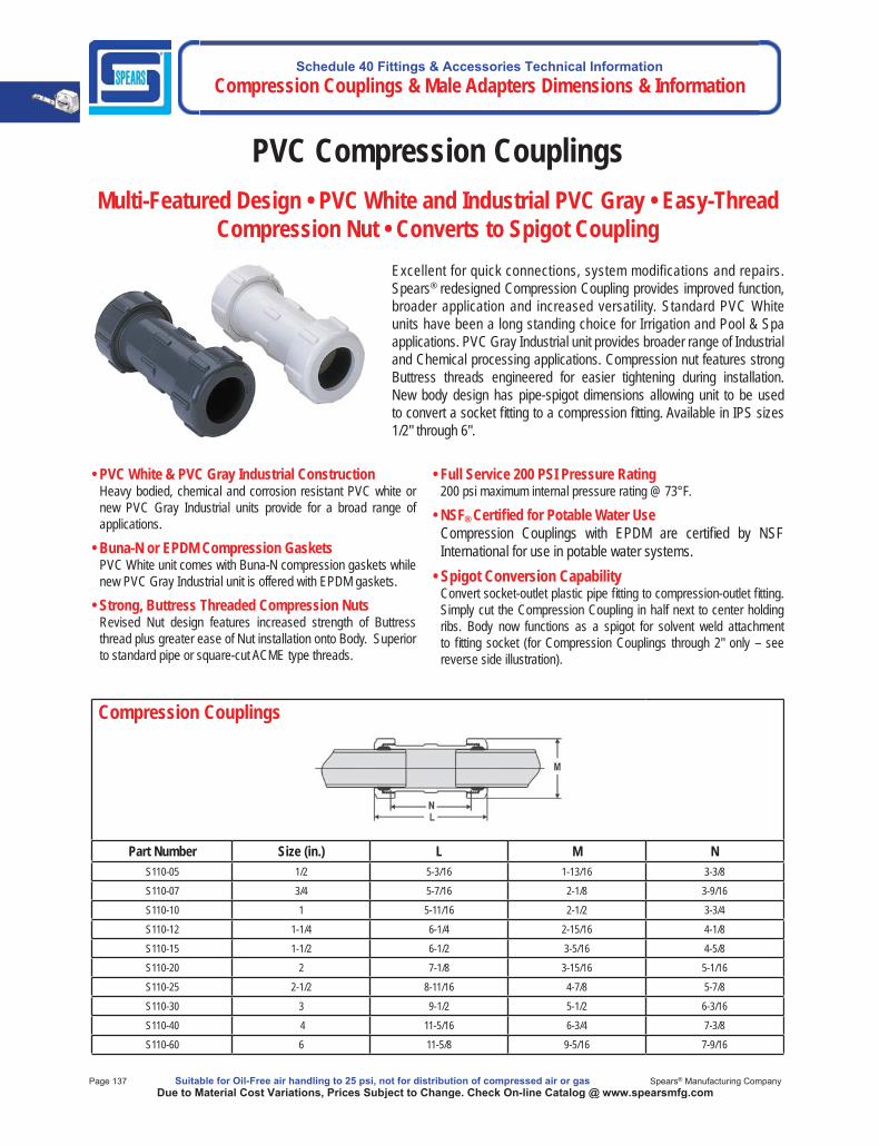
Schedule 40 Fittings & Accessories Technical Information Compression Couplings & Male Adapters Dimensions & Information
Page 137 Suitable for Oil-Free air handling to 25 psi, not for distribution of compressed air or gas Spears® Manufacturing CompanyDue to Material Cost Variations, Prices Subject to Change. Check On-line Catalog @ www.spearsmfg.com
Compression Couplings
Part Number Size (in.) L M N
S110-05 1/2 5-3/16 1-13/16 3-3/8
S110-07 3/4 5-7/16 2-1/8 3-9/16
S110-10 1 5-11/16 2-1/2 3-3/4
S110-12 1-1/4 6-1/4 2-15/16 4-1/8
S110-15 1-1/2 6-1/2 3-5/16 4-5/8
S110-20 2 7-1/8 3-15/16 5-1/16
S110-25 2-1/2 8-11/16 4-7/8 5-7/8
S110-30 3 9-1/2 5-1/2 6-3/16
S110-40 4 11-5/16 6-3/4 7-3/8
S110-60 6 11-5/8 9-5/16 7-9/16
PVC Compression CouplingsMulti-Featured Design • PVC White and Industrial PVC Gray • Easy-Thread
Compression Nut • Converts to Spigot CouplingExcellent for quick connections, system modifications and repairs.Spears® redesigned Compression Coupling provides improved function, broader application and increased versatility. Standard PVC Whiteunits have been a long standing choice for Irrigation and Pool & Spaapplications. PVC Gray Industrial unit provides broader range of Industrialand Chemical processing applications. Compression nut features strong Buttress threads engineered for easier tightening during installation.New body design has pipe-spigot dimensions allowing unit to be usedto convert a socket fi tting to a compression fi tting. Available in IPS sizes1/2" through 6".
• PVC White & PVC Gray Industrial ConstructionHeavy bodied, chemical and corrosion resistant PVC white or new PVC Gray Industrial units provide for a broad range of applications.
• Buna-N or EPDM Compression GasketsPVC White unit comes with Buna-N compression gaskets while new PVC Gray Industrial unit is offered with EPDM gaskets.
• Strong, Buttress Threaded Compression NutsRevised Nut design features increased strength of Buttress thread plus greater ease of Nut installation onto Body. Superior to standard pipe or square-cut ACME type threads.
• Full Service 200 PSI Pressure Rating 200 psi maximum internal pressure rating @ 73°F.
• NSF® Certifi ed for Potable Water UseCompression Couplings with EPDM are certifi ed by NSF International for use in potable water systems.
• Spigot Conversion CapabilityConvert socket-outlet plastic pipe fi tting to compression-outlet fi tting. Simply cut the Compression Coupling in half next to center holding ribs. Body now functions as a spigot for solvent weld attachment to fi tting socket (for Compression Couplings through 2" only – see reverse side illustration).

Schedule 40 Fittings & Accessories Technical InformationCompression Couplings & Male Adapters Dimensions & Information
Made in the U.S.A. Suitable for Oil-Free air handling to 25 psi, not for distribution of compressed air or gas Page 138Due to Material Cost Variations, Prices Subject to Change. Check On-line Catalog @ www.spearsmfg.com
Important Installation NoteWARNING: The compression joints provide a positive seal but do not restrain pipe from thrusts and movement under pressure. Use of compression joint requires blocking connecting pipe to prevent any movement. Failure to do so can result in system failure or severe personal injury. Use in cold water/ uid applications only.
Easy InstallationSpears® Compression Couplings easily install by simply sliding nut over pipe, slip on gasket, then insert into body and tighten nuts.
Convert Fittings to Compression OutletSocket type ttings 3/4" through 2-1/2" can be easily converted to compression outlets sizes 1/2” through 2” by simply cutting the Compression Coupling at the center holding ribs and solvent welding the spigot body into a tting socket.
Compression CouplingSize (in.)
Body SpigotSize (in.)
1/2 3/4
3/4 1
1 1-1/4
1-1/4 1-1/2
1-1/2 2
2 2-1/2
2-1/2 3
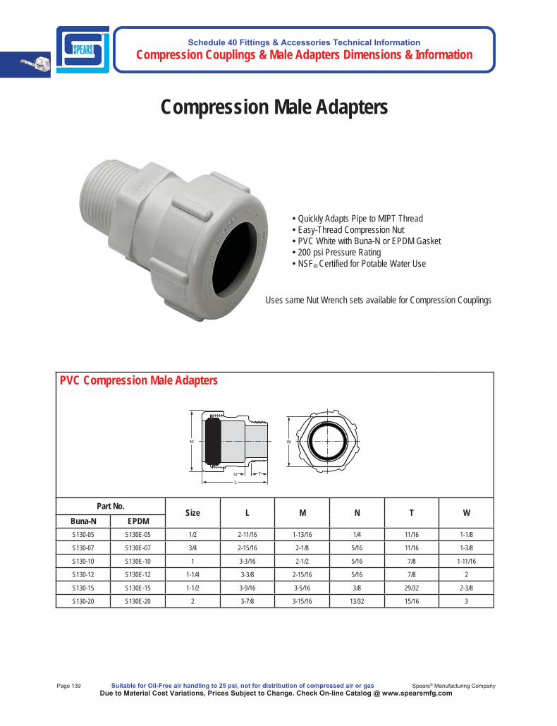
Schedule 40 Fittings & Accessories Technical Information Compression Couplings & Male Adapters Dimensions & Information
Page 139 Suitable for Oil-Free air handling to 25 psi, not for distribution of compressed air or gas Spears® Manufacturing CompanyDue to Material Cost Variations, Prices Subject to Change. Check On-line Catalog @ www.spearsmfg.com
PVC Compression Male Adapters
M
LN T
W
Part No.Size L M N T W
Buna-N EPDMS130-05 S130E-05 1/2 2-11/16 1-13/16 1/4 11/16 1-1/8
S130-07 S130E-07 3/4 2-15/16 2-1/8 5/16 11/16 1-3/8
S130-10 S130E-10 1 3-3/16 2-1/2 5/16 7/8 1-11/16
S130-12 S130E-12 1-1/4 3-3/8 2-15/16 5/16 7/8 2
S130-15 S130E-15 1-1/2 3-9/16 3-5/16 3/8 29/32 2-3/8
S130-20 S130E-20 2 3-7/8 3-15/16 13/32 15/16 3
• Quickly Adapts Pipe to MIPT Thread • Easy-Thread Compression Nut • PVC White with Buna-N or EPDM Gasket • 200 psi Pressure Rating • NSF® Certified for Potable Water Use
Uses same Nut Wrench sets available for Compression Couplings
Compression Male Adapters
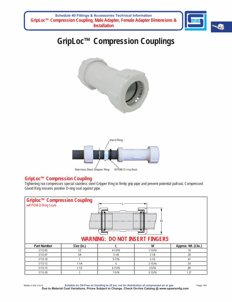
Schedule 40 Fittings & Accessories Technical InformationGripLoc™ Compression Coupling, Male Adapter, Female Adapter Dimensions &
Installation
Made in the U.S.A. Suitable for Oil-Free air handling to 25 psi, not for distribution of compressed air or gas Page 140Due to Material Cost Variations, Prices Subject to Change. Check On-line Catalog @ www.spearsmfg.com
Griploc™ Compression Couplingw/EPDM O-Ring Seals
Part Number Size (in.) L M Approx. Wt. (Lbs.)S112-05 1/2 4-13/16 1-13/16 .18S112-07 3/4 5-1/8 2-1/8 .28S112-10 1 5-7/16 2-1/2 .41S112-12 1-1/4 6 2-15/16 .54S112-15 1-1/2 6-11/16 3-5/16 .89S112-20 2 7-5/16 3-15/16 1.27
GripLoc™ Compression Coupling Tightening nut compresses special stainless steel Gripper Ring to firmly grip pipe and prevent potential pull-out. Compressed Gland Ring ensures positive O-ring seal against pipe.
GripLoc™ Compression Couplings
WARNING: DO NOT INSERT FINGERSWARNING: DO NOT INSERT FINGERS
L
M
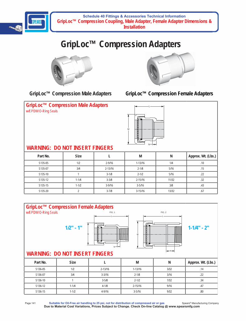
Schedule 40 Fittings & Accessories Technical Information GripLoc™ Compression Coupling, Male Adapter, Female Adapter Dimensions &
Installation
Page 141 Suitable for Oil-Free air handling to 25 psi, not for distribution of compressed air or gas Spears® Manufacturing CompanyDue to Material Cost Variations, Prices Subject to Change. Check On-line Catalog @ www.spearsmfg.com
GripLoc™ Compression Male Adaptersw/EPDM O-Ring Seals
Part No. Size L M N Approx. Wt. (Lbs.)S135-05 1/2 2-9/16 1-13/16 1/4 .10
S135-07 3/4 2-13/16 2-1/8 5/16 .15
S135-10 1 3-1/8 2-1/2 5/16 .22
S135-12 1-1/4 3-3/8 2-15/16 11/32 .32
S135-15 1-1/2 3-9/16 3-5/16 3/8 .43
S135-20 2 3-7/8 3-15/16 13/32 .67
GripLoc™ Compression Female Adaptersw/EPDM O-Ring Seals
Part No. Size L M N Approx. Wt. (Lbs.)S136-05 1/2 2-13/16 1-13/16 3/32 .14
S136-07 3/4 3-3/16 2-1/8 3/16 .22
S136-10 1 3-5/8 2-1/2 7/32 .34
S136-12 1-1/4 4-1/8 2-15/16 9/16 .47
S136-15 1-1/2 4-9/16 3-5/16 9/32 .80
GripLoc™ Compression Adapters
1/2" - 1" 1-1/4" - 2"
GripLoc™ Compression Male Adapters GripLoc™ Compression Female Adapters
WARNING: DO NOT INSERT FINGERSWARNING: DO NOT INSERT FINGERS
L
M
N
WARNING: DO NOT INSERT FINGERSWARNING: DO NOT INSERT FINGERS
M
L
FIG. 2
M
L
FIG. 1
N
N
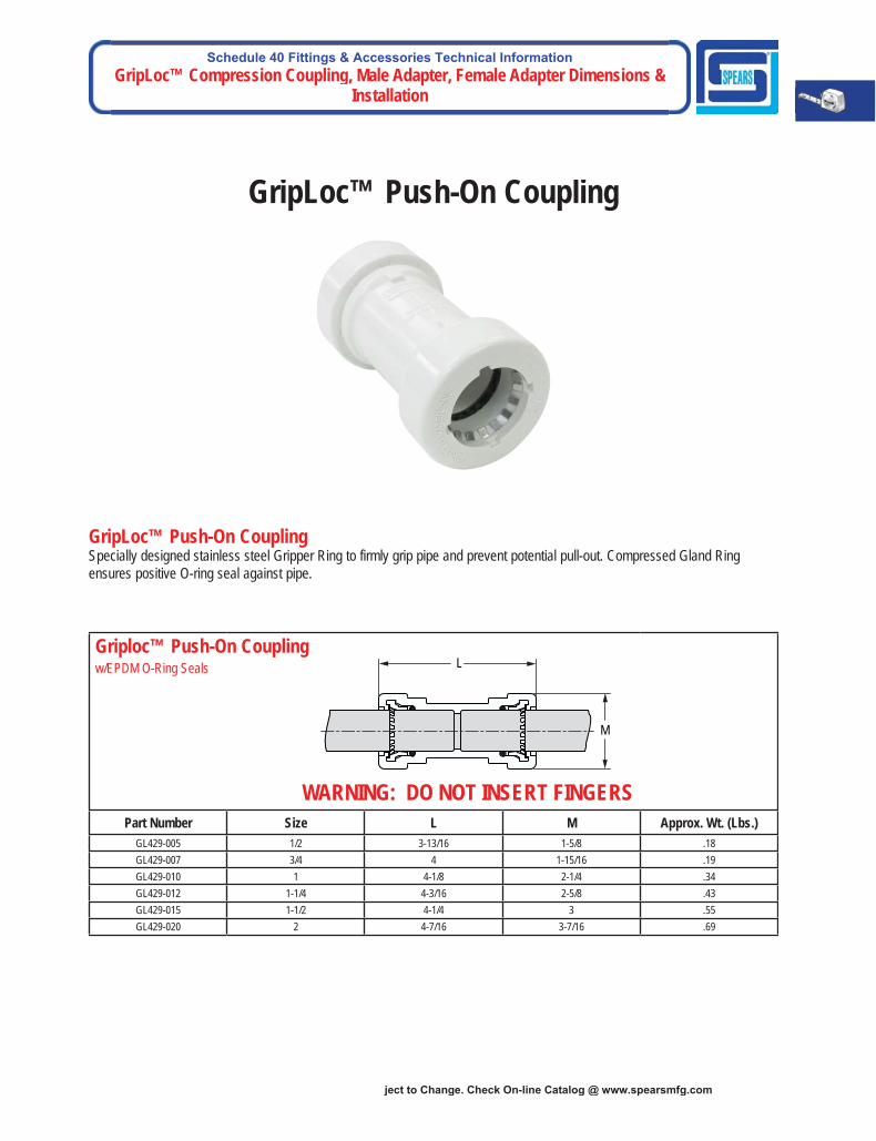
Schedule 40 Fittings & Accessories Technical InformationGripLoc™ Compression Coupling, Male Adapter, Female Adapter Dimensions &
Installation
ject to Change. Check On-line Catalog @ www.spearsmfg.com
GripLoc™ Push-On Coupling
Griploc™ Push-On Couplingw/EPDM O-Ring Seals
Part Number Size L M Approx. Wt. (Lbs.)GL429-005 1/2 3-13/16 1-5/8 .18GL429-007 3/4 4 1-15/16 .19GL429-010 1 4-1/8 2-1/4 .34GL429-012 1-1/4 4-3/16 2-5/8 .43GL429-015 1-1/2 4-1/4 3 .55GL429-020 2 4-7/16 3-7/16 .69
WARNING: DO NOT INSERT FINGERSWARNING: DO NOT INSERT FINGERS
L
M
GripLoc™ Push-On Coupling Specially designed stainless steel Gripper Ring to firmly grip pipe and prevent potential pull-out. Compressed Gland Ring ensures positive O-ring seal against pipe.
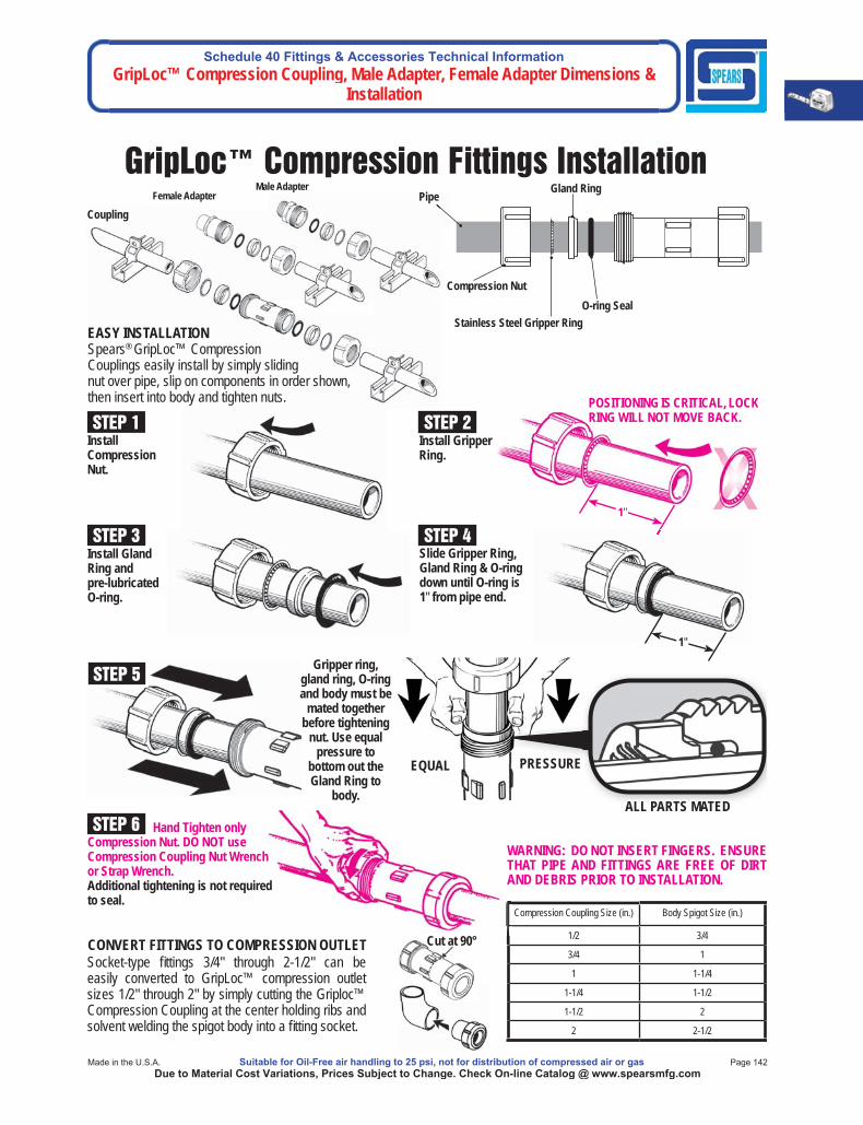
Schedule 40 Fittings & Accessories Technical InformationGripLoc™ Compression Coupling, Male Adapter, Female Adapter Dimensions &
Installation
Made in the U.S.A. Suitable for Oil-Free air handling to 25 psi, not for distribution of compressed air or gas Page 142Due to Material Cost Variations, Prices Subject to Change. Check On-line Catalog @ www.spearsmfg.com
GripLoc™ Compression Fittings InstallationMale Adapter
Female Adapter
Stainless Steel Gripper Ring
Compression NutO-ring Seal
Gland RingPipe
Compression Coupling Size (in.) Body Spigot Size (in.)
1/2 3/4
3/4 1
1 1-1/4
1-1/4 1-1/2
1-1/2 2
2 2-1/2
STEP 1
Coupling
STEP 2
11""
POSITIONING IS CRITICAL, LOCK RING WILL NOT MOVE BACK.
STEP 5
EQUAL PRESSURE
STEP 4
11""
STEP 3Install Gland Ring and pre-lubricated O-ring.
Install Compression Nut.
Install Gripper Ring.
PRESSURE
ALL PARTS MATEDALL PARTS MATED
Socket-type fi ttings 3/4" through 2-1/2" can be easily converted to GripLoc™ compression outlet sizes 1/2" through 2" by simply cutting the Griploc™ Compression Coupling at the center holding ribs and solvent welding the spigot body into a fi tting socket.
CONVERT FITTINGS TO COMPRESSION OUTLET
STEP 6
Cut at 90°
WARNING: DO NOT INSERT FINGERS. ENSURE WARNING: DO NOT INSERT FINGERS. ENSURE THAT PIPE AND FITTINGS ARE FREE OF DIRT THAT PIPE AND FITTINGS ARE FREE OF DIRT AND DEBRIS PRIOR TO INSTALLATION.AND DEBRIS PRIOR TO INSTALLATION.
EASY INSTALLATIONSpears® GripLoc™ Compression Couplings easily install by simply sliding nut over pipe, slip on components in order shown, then insert into body and tighten nuts.
Gripper ring, gland ring, O-ring and body must be
mated together before tightening
nut. Use equal pressure to
bottom out the Gland Ring to
body.
Slide Gripper Ring, Gland Ring & O-ring down until O-ring is 1" from pipe end.
Hand Tighten only Compression Nut. DO NOT use Compression Coupling Nut Wrench or Strap Wrench. Additional tightening is not required to seal.
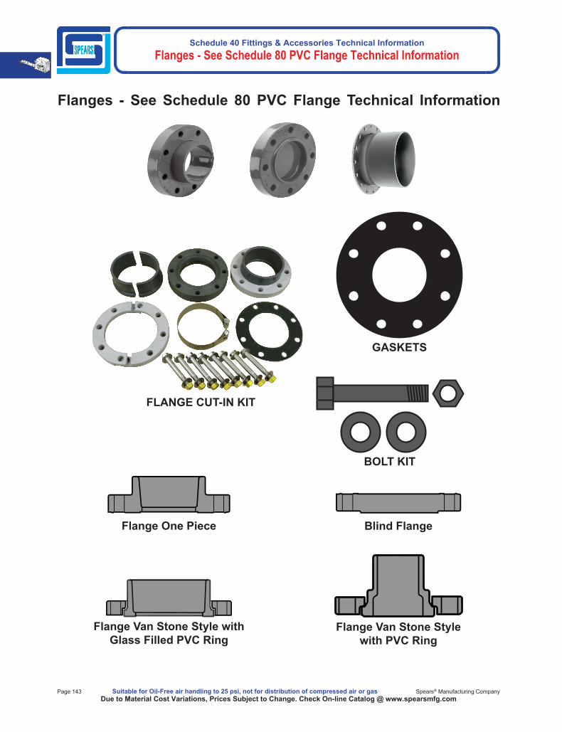
Schedule 40 Fittings & Accessories Technical Information Flanges - See Schedule 80 PVC Flange Technical Information
Page 143 Suitable for Oil-Free air handling to 25 psi, not for distribution of compressed air or gas Spears® Manufacturing CompanyDue to Material Cost Variations, Prices Subject to Change. Check On-line Catalog @ www.spearsmfg.com
Flanges - See Schedule 80 PVC Flange Technical Information
BOLT KIT
GASKETS
FLANGE CUT-IN KIT
Flange One Piece Blind Flange
Flange Van Stone Style with Glass Filled PVC Ring
Flange Van Stone Style with PVC Ring