Embed Size (px)
Citation preview
w w w . p r i m e c o n d u i t . c o m
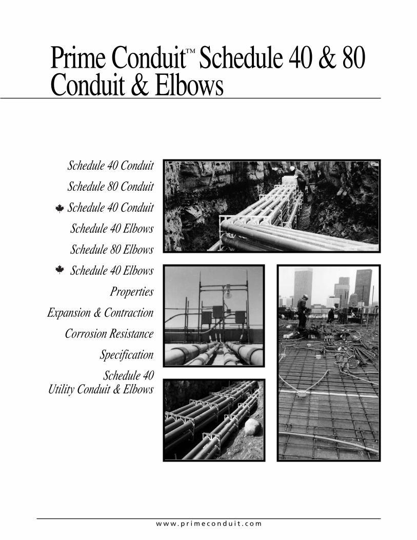
Prime Conduit™ Schedule 40 & 80Conduit & Elbows
Schedule 40 Conduit
Schedule 80 Conduit
Schedule 40 Conduit
Schedule 40 Elbows
Schedule 80 Elbows
Schedule 40 Elbows
Properties
Expansion & Contraction
Corrosion Resistance
Specification
Schedule 40 Utility Conduit & Elbows
w w w . p r i m e c o n d u i t . c o m2
Rigid Nonmetallic Conduit – Schedule 40 and Schedule 80
Prime Conduit™ manufactures the most complete line of nonmetallic conduits in the electrical industry. Prime ConduitSchedule 40 and Schedule 80 conduits are designed for useaboveground and underground as described in the NationalElectrical Code. Specify only Prime Conduit conduits to insureraceway system quality.
FeaturesEase of Installation Nonmetallic conduits are 1/4 to 1/5the weight of metallic systems, can be installed in less thanhalf the time, and are easily fabricated on the job.
Safety Nonmetallic conduits are nonconductive, assuring asafe system.
Impact Resistant Prime Conduit Schedule 40 andSchedule 80 nonmetallic conduits are resistant to sunlightand are listed for exposed or outdoor usage.
Corrosion Resistant Prime Conduit conduits are nonmetallic and will not rust or corrode.Prime Conduit nonmetallic Schedule 40 and Schedule 80 conduits and elbows are manufactured to NEMA TC-2,Federal specification WC1O94A and UL 651 specifications.The conduit carries respective ETL Listings and ETL labels.
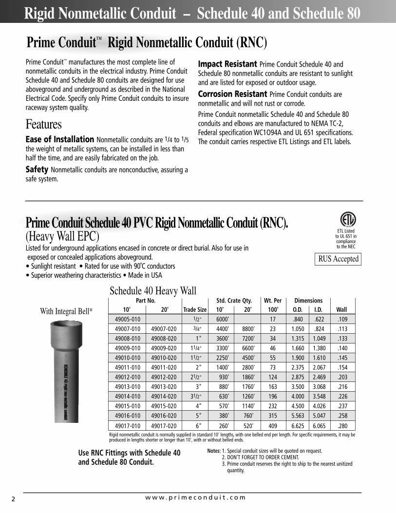
Part No. Std. Crate Qty. Wt. Per Dimensions10' 20' Trade Size 10' 20' 100' O.D. I.D. Wall
49005-010 1/2" 6000' 17 .840 .622 .109
49007-010 49007-020 3/4" 4400' 8800' 23 1.050 .824 .113
49008-010 49008-020 1" 3600' 7200' 34 1.315 1.049 .133
49009-010 49009-020 11/4" 3300' 6600' 46 1.660 1.380 .140
49010-010 49010-020 11/2" 2250' 4500' 55 1.900 1.610 .145
49011-010 49011-020 2" 1400' 2800' 73 2.375 2.067 .154
49012-010 49012-020 21/2" 930' 1860' 124 2.875 2.469 .203
49013-010 49013-020 3" 880' 1760' 163 3.500 3.068 .216
49014-010 49014-020 31/2" 630' 1260' 196 4.000 3.548 .226
49015-010 49015-020 4" 570' 1140' 232 4.500 4.026 .237
49016-010 49016-020 5" 380' 760' 315 5.563 5.047 .258
49017-010 49017-020 6" 260' 520' 409 6.625 6.065 .280
With Integral Bell*
Prime Conduit Schedule 40 PVC Rigid Nonmetallic Conduit (RNC).(Heavy Wall EPC)Listed for underground applications encased in concrete or direct burial. Also for use inexposed or concealed applications aboveground.• Sunlight resistant • Rated for use with 90˚C conductors • Superior weathering characteristics • Made in USA
Schedule 40 Heavy Wall
Rigid nonmetallic conduit is normally supplied in standard 10' lengths, with one belled end per length. For specific requirements, it may beproduced in lengths shorter or longer than 10', with or without belled ends.
ETL Listed to UL 651 in complianceto the NEC
Use RNC Fittings with Schedule 40 and Schedule 80 Conduit.
Notes: 1. Special conduit sizes will be quoted on request.2. DON’T FORGET TO ORDER CEMENT.3. Prime conduit reserves the right to ship to the nearest unitized
quantity.
RUS Accepted
Prime Conduit™ Rigid Nonmetallic Conduit (RNC)
w w w . p r i m e c o n d u i t . c o m 3
Rigid Nonmetallic Conduit – Support in Aboveground Installations
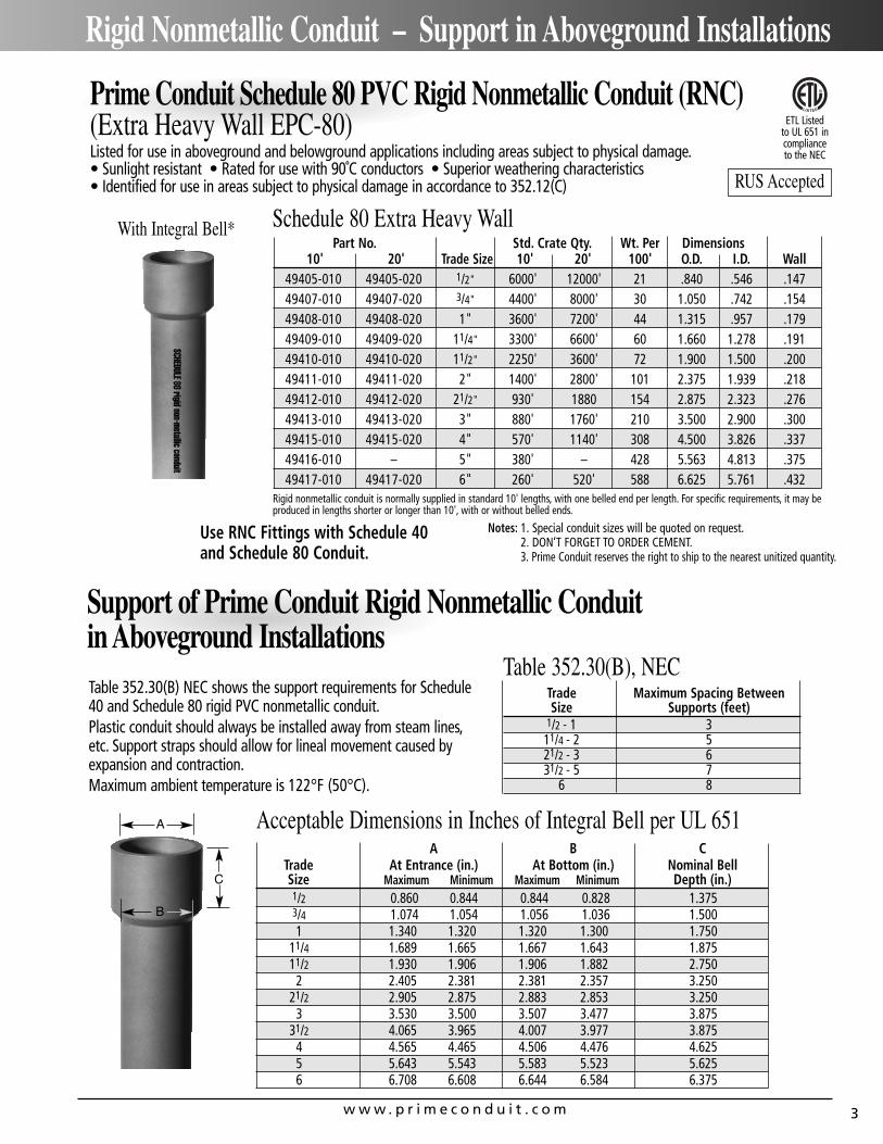
Part No. Std. Crate Qty. Wt. Per Dimensions10' 20' Trade Size 10' 20' 100' O.D. I.D. Wall
49405-010 49405-020 1/2" 6000' 12000' 21 .840 .546 .14749407-010 49407-020 3/4" 4400' 8000' 30 1.050 .742 .15449408-010 49408-020 1" 3600' 7200' 44 1.315 .957 .17949409-010 49409-020 11/4" 3300' 6600' 60 1.660 1.278 .19149410-010 49410-020 11/2" 2250' 3600' 72 1.900 1.500 .20049411-010 49411-020 2" 1400' 2800' 101 2.375 1.939 .21849412-010 49412-020 21/2" 930' 1880 154 2.875 2.323 .27649413-010 49413-020 3" 880' 1760' 210 3.500 2.900 .30049415-010 49415-020 4" 570' 1140' 308 4.500 3.826 .33749416-010 – 5" 380' – 428 5.563 4.813 .37549417-010 49417-020 6" 260' 520' 588 6.625 5.761 .432
With Integral Bell*
Use RNC Fittings with Schedule 40 and Schedule 80 Conduit.
Notes: 1. Special conduit sizes will be quoted on request.2. DON’T FORGET TO ORDER CEMENT.3. Prime Conduit reserves the right to ship to the nearest unitized quantity.
Prime Conduit Schedule 80 PVC Rigid Nonmetallic Conduit (RNC)(Extra Heavy Wall EPC-80)Listed for use in aboveground and belowground applications including areas subject to physical damage.• Sunlight resistant • Rated for use with 90˚C conductors • Superior weathering characteristics• Identified for use in areas subject to physical damage in accordance to 352.12(C)
Schedule 80 Extra Heavy Wall
Rigid nonmetallic conduit is normally supplied in standard 10' lengths, with one belled end per length. For specific requirements, it may beproduced in lengths shorter or longer than 10', with or without belled ends.
Support of Prime Conduit Rigid Nonmetallic Conduit in Aboveground InstallationsTable 352.30(B) NEC shows the support requirements for Schedule40 and Schedule 80 rigid PVC nonmetallic conduit.Plastic conduit should always be installed away from steam lines,etc. Support straps should allow for lineal movement caused byexpansion and contraction.Maximum ambient temperature is 122°F (50°C).
Table 352.30(B), NECTrade Maximum Spacing BetweenSize Supports (feet)
1/2 - 1 311/4 - 2 521/2 - 3 631/2 - 5 7
6 8
Acceptable Dimensions in Inches of Integral Bell per UL 651A B C
Trade At Entrance (in.) At Bottom (in.) Nominal BellSize Maximum Minimum Maximum Minimum Depth (in.)1/2 0.860 0.844 0.844 0.828 1.3753/4 1.074 1.054 1.056 1.036 1.5001 1.340 1.320 1.320 1.300 1.750
11/4 1.689 1.665 1.667 1.643 1.87511/2 1.930 1.906 1.906 1.882 2.750
2 2.405 2.381 2.381 2.357 3.25021/2 2.905 2.875 2.883 2.853 3.250
3 3.530 3.500 3.507 3.477 3.87531/2 4.065 3.965 4.007 3.977 3.875
4 4.565 4.465 4.506 4.476 4.6255 5.643 5.543 5.583 5.523 5.6256 6.708 6.608 6.644 6.584 6.375
A
B
C
ETL Listed to UL 651 in complianceto the NEC
RUS Accepted
w w w . p r i m e c o n d u i t . c o m4
Canadian Rigid Nonmetallic Conduit – Schedule 40
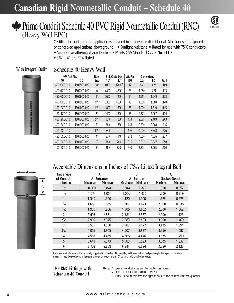
With Integral Bell*
Prime Conduit Schedule 40 PVC Rigid Nonmetallic Conduit (RNC)(Heavy Wall EPC)
Certified for underground applications encased in concrete or direct burial. Also for use in exposed or concealed applications aboveground. • Sunlight resistant • Rated for use with 75˚C conductors • Superior weathering characteristics • Meets CSA Standard C22.2 No. 211.2 • 3/4"– 4" are FT-4 Rated
Schedule 40 Heavy Wall
Rigid nonmetallic conduit is normally supplied in standard 10' lengths, with one belled end per length. For specific require-ments, it may be produced in lengths shorter or longer than 10', with or without belled ends.
Use RNC Fittings withSchedule 40 Conduit.
Notes: 1. Special conduit sizes will be quoted on request.2. DON’T FORGET TO ORDER CEMENT.3. Prime Conduit reserves the right to ship to the nearest unitized quantity.
LR90813
Part No. Nom. Std. Crate Qty. Wt. Per Dimensions10' 20' Size 10' 20' 100' O.D. I.D. Wall
49005CC-010 49005CC-020 1/2" 6000' 12000' 17 .840 .622 .109
49007CC-010 49007CC-020 3/4" 4400' 8800' 23 1.050 .824 .113
49008CC-010 49008CC-020 1" 3600' 7200' 34 1.315 1.049 .133
49009CC-010 49009CC-020 11/4" 3300' 6600' 46 1.660 1.380 .140
49010CC-010 49010CC-020 11/2" 1800' 3600' 55 1.900 1.610 .145
49011CC-010 49011CC-020 2" 1400' 2800' 73 2.375 2.067 .154
49012CC-010 49012CC-020 21/2" 930' 1860' 124 2.875 2.469 .203
49013CC-010 49013CC-020 3" 880' 1760' 163 3.500 3.068 .216
49014CC-010 – 31/2" 630' – 196 4.000 3.548 .226
49015CC-010 49015CC-020 4" 570' 1140' 232 4.500 4.026 .237
49016CC-010 49016CC-020 5" 380' 760' 315 5.563 5.047 .258
49017CC-010 49017CC-020 6" 260' 520' 409 6.625 6.065 .280
Acceptable Dimensions in Inches of CSA Listed Integral BellTrade Size A B Cof Conduit At Entrance At Bottom Socket Depth
in Inches Maximum Minimum Maximum Minimum Maximum Minimum1/2 0.860 0.844 0.844 0.828 1.500 0.6523/4 1.074 1.054 1.056 1.036 1.500 0.7191 1.340 1.320 1.320 1.300 1.875 0.875
11/4 1.689 1.665 1.667 1.643 2.000 0.93811/2 1.930 1.906 1.906 1.882 2.000 1.062
2 2.405 2.381 2.381 2.357 2.000 1.12521/2 2.905 2.875 2.883 2.853 3.000 1.469
3 3.530 3.500 3.507 3.477 3.125 1.59431/2 4.065 3.965 4.007 3.977 3.250 1.687
4 4.565 4.465 4.506 4.476 3.375 1.7505 5.643 5.543 5.583 5.523 3.625 1.9376 6.708 6.608 6.644 6.584 3.750 2.125
A
B
C
w w w . p r i m e c o n d u i t . c o m 5
Rigid Nonmetallic Conduit – Elbows
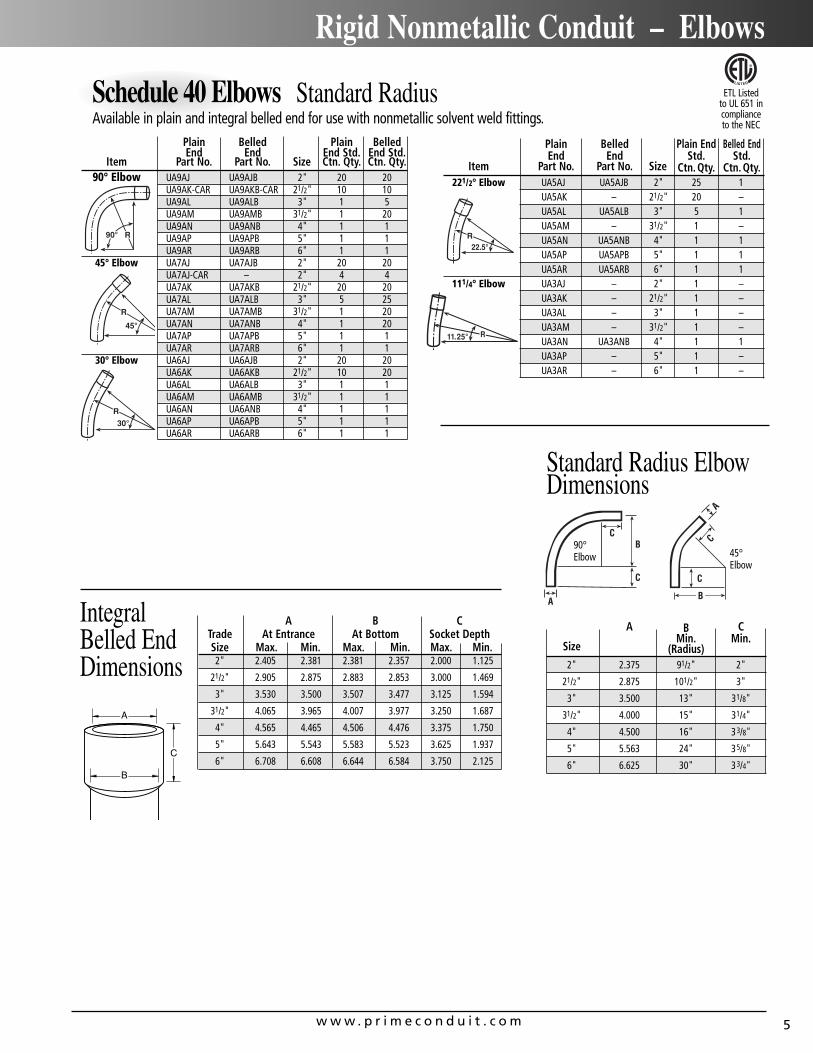
Plain Belled Plain BelledEnd End End Std. End Std.
Item Part No. Part No. Size Ctn. Qty. Ctn. Qty.90° Elbow UA9AJ UA9AJB 2" 20 20
UA9AK-CAR UA9AKB-CAR 21/2" 10 10UA9AL UA9ALB 3" 1 5UA9AM UA9AMB 31/2" 1 20UA9AN UA9ANB 4" 1 1UA9AP UA9APB 5" 1 1UA9AR UA9ARB 6" 1 1
45° Elbow UA7AJ UA7AJB 2" 20 20UA7AJ-CAR – 2" 4 4UA7AK UA7AKB 21/2" 20 20UA7AL UA7ALB 3" 5 25UA7AM UA7AMB 31/2" 1 20UA7AN UA7ANB 4" 1 20UA7AP UA7APB 5" 1 1UA7AR UA7ARB 6" 1 1
30° Elbow UA6AJ UA6AJB 2" 20 20UA6AK UA6AKB 21/2" 10 20UA6AL UA6ALB 3" 1 1UA6AM UA6AMB 31/2" 1 1UA6AN UA6ANB 4" 1 1UA6AP UA6APB 5" 1 1UA6AR UA6ARB 6" 1 1
Schedule 40 Elbows Standard RadiusAvailable in plain and integral belled end for use with nonmetallic solvent weld fittings.
Plain Belled Plain End Belled EndEnd End Std. Std.
Item Part No. Part No. Size Ctn. Qty. Ctn. Qty.221/2° Elbow UA5AJ UA5AJB 2" 25 1
UA5AK – 21/2" 20 –UA5AL UA5ALB 3" 5 1UA5AM – 31/2" 1 –UA5AN UA5ANB 4" 1 1UA5AP UA5APB 5" 1 1UA5AR UA5ARB 6" 1 1
111/4° Elbow UA3AJ – 2" 1 –UA3AK – 21/2" 1 –UA3AL – 3" 1 –UA3AM – 31/2" 1 –UA3AN UA3ANB 4" 1 1UA3AP – 5" 1 –UA3AR – 6" 1 –
A B CMin. Min.
Size (Radius)2" 2.375 91/2" 2"
21/2" 2.875 101/2" 3"
3" 3.500 13" 31/8"
31/2" 4.000 15" 31/4"
4" 4.500 16" 33/8"
5" 5.563 24" 35/8"
6" 6.625 30" 33/4"
A B CTrade At Entrance At Bottom Socket DepthSize Max. Min. Max. Min. Max. Min.2" 2.405 2.381 2.381 2.357 2.000 1.125
21/2" 2.905 2.875 2.883 2.853 3.000 1.469
3" 3.530 3.500 3.507 3.477 3.125 1.594
31/2" 4.065 3.965 4.007 3.977 3.250 1.687
4" 4.565 4.465 4.506 4.476 3.375 1.750
5" 5.643 5.543 5.583 5.523 3.625 1.937
6" 6.708 6.608 6.644 6.584 3.750 2.125
Standard Radius Elbow Dimensions
A
C
B
IntegralBelled EndDimensions
90°Elbow 45°
Elbow
ETL Listed to UL 651 in complianceto the NEC
w w w . p r i m e c o n d u i t . c o m6
Rigid Nonmetallic Conduit – Elbows
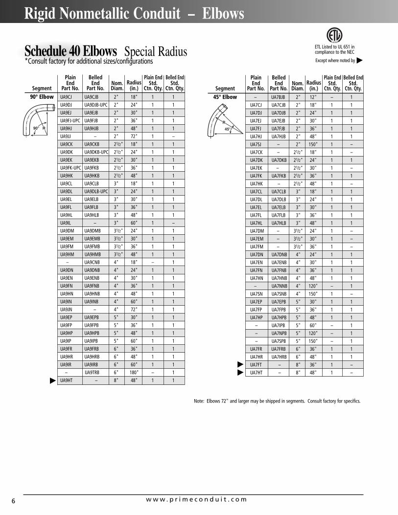
Schedule 40 Elbows Special Radius *Consult factory for additional sizes/configurations
Plain Belled Plain End Belled EndEnd End Nom. Radius Std. Std.
Segment Part No. Part No. Diam. (in.) Ctn. Qty. Ctn. Qty.90° Elbow UA9CJ UA9CJB 2" 18" 1 1
UA9DJ UA9DJB-UPC 2" 24" 1 1
UA9EJ UA9EJB 2" 30" 1 1
UA9FJ-UPC UA9FJB 2" 36" 1 1
UA9HJ UA9HJB 2" 48" 1 1
UA9JJ – 2" 72" 1 –
UA9CK UA9CKB 21/2" 18" 1 1
UA9DK UA9DKB-UPC 21/2" 24" 1 1
UA9EK UA9EKB 21/2" 30" 1 1
UA9FK-UPC UA9FKB 21/2" 36" 1 1
UA9HK UA9HKB 21/2" 48" 1 1
UA9CL UA9CLB 3" 18" 1 1
UA9DL UA9DLB-UPC 3" 24" 1 1
UA9EL UA9ELB 3" 30" 1 1
UA9FL UA9FLB 3" 36" 1 1
UA9HL UA9HLB 3" 48" 1 1
UA9IL – 3" 60" 1 –
UA9DM UA9DMB 31/2" 24" 1 1
UA9EM UA9EMB 31/2" 30" 1 1
UA9FM UA9FMB 31/2" 36" 1 1
UA9HM UA9HMB 31/2" 48" 1 1
– UA9CNB 4" 18" – 1
UA9DN UA9DNB 4" 24" 1 1
UA9EN UA9ENB 4" 30" 1 1
UA9FN UA9FNB 4" 36" 1 1
UA9HN UA9HNB 4" 48" 1 1
UA9IN UA9INB 4" 60" 1 1
UA9JN – 4" 72" 1 1
UA9EP UA9EPB 5" 30" 1 1
UA9FP UA9FPB 5" 36" 1 1
UA9HP UA9HPB 5" 48" 1 1
UA9IP UA9IPB 5" 60" 1 1
UA9FR UA9FRB 6" 36" 1 1
UA9HR UA9HRB 6" 48" 1 1
UA9IR UA9IRB 6" 60" 1 1
– UA9TRB 6" 180" – 1
UA9HT – 8" 48" 1 1
Plain Belled Plain End Belled EndEnd End Nom. Radius Std. Std.
Segment Part No. Part No. Diam. (in.) Ctn. Qty. Ctn. Qty.45° Elbow – UA7BJB 2" 12" – 1
UA7CJ UA7CJB 2" 18" 1 1
UA7DJ UA7DJB 2" 24" 1 1
UA7EJ UA7EJB 2" 30" 1 1
UA7FJ UA7FJB 2" 36" 1 1
UA7HJ UA7HJB 2" 48" 1 1
UA7SJ – 2" 150" 1 –
UA7CK – 21/2" 18" 1 –
UA7DK UA7DKB 21/2" 24" 1 1
UA7EK – 21/2" 30" 1 –
UA7FK UA7FKB 21/2" 36" 1 1
UA7HK – 21/2" 48" 1 –
UA7CL UA7CLB 3" 18" 1 1
UA7DL UA7DLB 3" 24" 1 1
UA7EL UA7ELB 3" 30" 1 1
UA7FL UA7FLB 3" 36" 1 1
UA7HL UA7HLB 3" 48" 1 1
UA7DM – 31/2" 24" 1 –
UA7EM – 31/2" 30" 1 –
UA7FM – 31/2" 36" 1 –
UA7DN UA7DNB 4" 24" 1 1
UA7EN UA7ENB 4" 30" 1 1
UA7FN UA7FNB 4" 36" 1 1
UA7HN UA7HNB 4" 48" 1 1
– UA7NNB 4" 120" – 1
UA7SN UA7SNB 4" 150" 1 –
UA7EP UA7EPB 5" 30" 1 1
UA7FP UA7FPB 5" 36" 1 1
UA7HP UA7HPB 5" 48" 1 1
– UA7IPB 5" 60" – 1
– UA7NPB 5" 120" – 1
– UA7SPB 5" 150" – 1
UA7FR UA7FRB 6" 36" 1 1
UA7HR UA7HRB 6" 48" 1 1
UA7FT – 8" 36" 1 –
UA7HT – 8" 48" 1 –
ETL Listed to UL 651 in compliance to the NEC
Note: Elbows 72" and larger may be shipped in segments. Consult factory for specifics.
Except where noted by
w w w . p r i m e c o n d u i t . c o m 7
Rigid Nonmetallic Conduit – Elbows
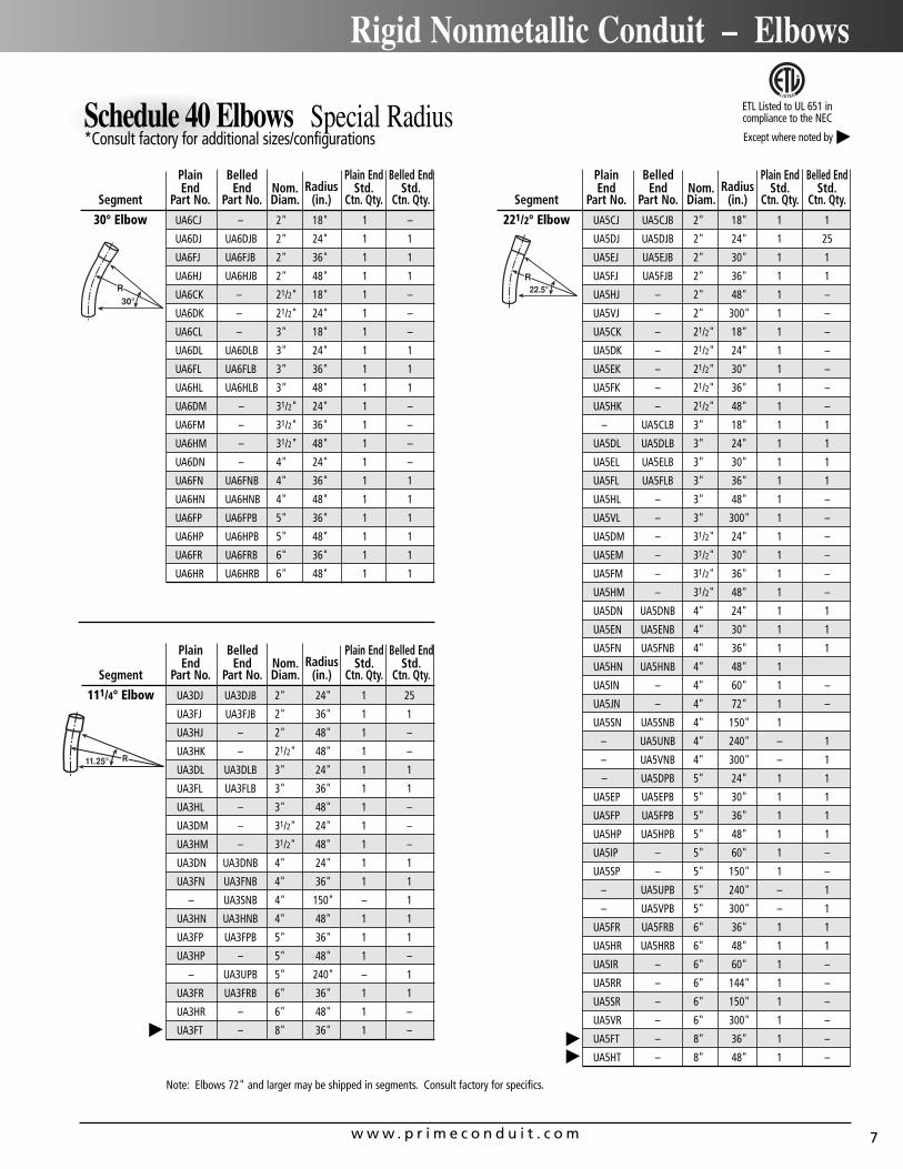
Schedule 40 Elbows Special Radius *Consult factory for additional sizes/configurations
Plain Belled Plain End Belled EndEnd End Nom. Radius Std. Std.
Segment Part No. Part No. Diam. (in.) Ctn. Qty. Ctn. Qty.
30° Elbow UA6CJ – 2" 18" 1 –
UA6DJ UA6DJB 2" 24" 1 1
UA6FJ UA6FJB 2" 36" 1 1
UA6HJ UA6HJB 2" 48" 1 1
UA6CK – 21/2" 18" 1 –
UA6DK – 21/2" 24" 1 –
UA6CL – 3" 18" 1 –
UA6DL UA6DLB 3" 24" 1 1
UA6FL UA6FLB 3" 36" 1 1
UA6HL UA6HLB 3" 48" 1 1
UA6DM – 31/2" 24" 1 –
UA6FM – 31/2" 36" 1 –
UA6HM – 31/2" 48" 1 –
UA6DN – 4" 24" 1 –
UA6FN UA6FNB 4" 36" 1 1
UA6HN UA6HNB 4" 48" 1 1
UA6FP UA6FPB 5" 36" 1 1
UA6HP UA6HPB 5" 48" 1 1
UA6FR UA6FRB 6" 36" 1 1
UA6HR UA6HRB 6" 48" 1 1
Plain Belled Plain End Belled EndEnd End Nom. Radius Std. Std.
Segment Part No. Part No. Diam. (in.) Ctn. Qty. Ctn. Qty.
111/4° Elbow UA3DJ UA3DJB 2" 24" 1 25
UA3FJ UA3FJB 2" 36" 1 1
UA3HJ – 2" 48" 1 –
UA3HK – 21/2" 48" 1 –
UA3DL UA3DLB 3" 24" 1 1
UA3FL UA3FLB 3" 36" 1 1
UA3HL – 3" 48" 1 –
UA3DM – 31/2" 24" 1 –
UA3HM – 31/2" 48" 1 –
UA3DN UA3DNB 4" 24" 1 1
UA3FN UA3FNB 4" 36" 1 1
– UA3SNB 4" 150" – 1
UA3HN UA3HNB 4" 48" 1 1
UA3FP UA3FPB 5" 36" 1 1
UA3HP – 5" 48" 1 –
– UA3UPB 5" 240" – 1
UA3FR UA3FRB 6" 36" 1 1
UA3HR – 6" 48" 1 –
UA3FT – 8" 36" 1 –
Plain Belled Plain End Belled EndEnd End Nom. Radius Std. Std.
Segment Part No. Part No. Diam. (in.) Ctn. Qty. Ctn. Qty.
221/2° Elbow UA5CJ UA5CJB 2" 18" 1 1
UA5DJ UA5DJB 2" 24" 1 25
UA5EJ UA5EJB 2" 30" 1 1
UA5FJ UA5FJB 2" 36" 1 1
UA5HJ – 2" 48" 1 –
UA5VJ – 2" 300" 1 –
UA5CK – 21/2" 18" 1 –
UA5DK – 21/2" 24" 1 –
UA5EK – 21/2" 30" 1 –
UA5FK – 21/2" 36" 1 –
UA5HK – 21/2" 48" 1 –
– UA5CLB 3" 18" 1 1
UA5DL UA5DLB 3" 24" 1 1
UA5EL UA5ELB 3" 30" 1 1
UA5FL UA5FLB 3" 36" 1 1
UA5HL – 3" 48" 1 –
UA5VL – 3" 300" 1 –
UA5DM – 31/2" 24" 1 –
UA5EM – 31/2" 30" 1 –
UA5FM – 31/2" 36" 1 –
UA5HM – 31/2" 48" 1 –
UA5DN UA5DNB 4" 24" 1 1
UA5EN UA5ENB 4" 30" 1 1
UA5FN UA5FNB 4" 36" 1 1
UA5HN UA5HNB 4" 48" 1
UA5IN – 4" 60" 1 –
UA5JN – 4" 72" 1 –
UA5SN UA5SNB 4" 150" 1
– UA5UNB 4" 240" – 1
– UA5VNB 4" 300" – 1
– UA5DPB 5" 24" 1 1
UA5EP UA5EPB 5" 30" 1 1
UA5FP UA5FPB 5" 36" 1 1
UA5HP UA5HPB 5" 48" 1 1
UA5IP – 5" 60" 1 –
UA5SP – 5" 150" 1 –
– UA5UPB 5" 240" – 1
– UA5VPB 5" 300" – 1
UA5FR UA5FRB 6" 36" 1 1
UA5HR UA5HRB 6" 48" 1 1
UA5IR – 6" 60" 1 –
UA5RR – 6" 144" 1 –
UA5SR – 6" 150" 1 –
UA5VR – 6" 300" 1 –
UA5FT – 8" 36" 1 –
UA5HT – 8" 48" 1 –
Note: Elbows 72" and larger may be shipped in segments. Consult factory for specifics.
ETL Listed to UL 651 in compliance to the NEC
Except where noted by
w w w . p r i m e c o n d u i t . c o m8
Rigid Nonmetallic Conduit – Elbows
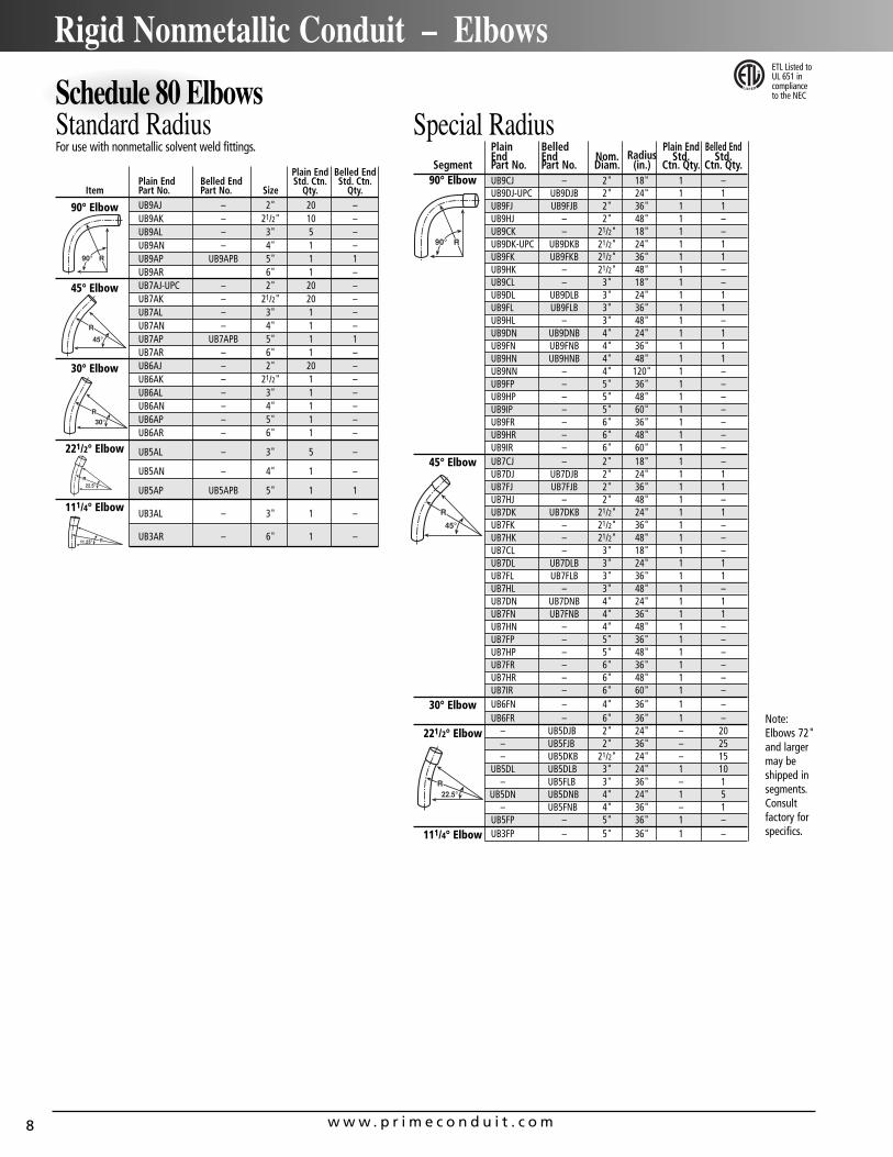
Schedule 80 ElbowsStandard RadiusFor use with nonmetallic solvent weld fittings.
Special RadiusPlain Belled Plain End Belled EndEnd End Nom. Radius Std. Std.
Segment Part No. Part No. Diam. (in.) Ctn. Qty. Ctn. Qty.90° Elbow UB9CJ – 2" 18" 1 –
UB9DJ-UPC UB9DJB 2" 24" 1 1UB9FJ UB9FJB 2" 36" 1 1UB9HJ – 2" 48" 1 –UB9CK – 21/2" 18" 1 –UB9DK-UPC UB9DKB 21/2" 24" 1 1UB9FK UB9FKB 21/2" 36" 1 1UB9HK – 21/2" 48" 1 –UB9CL – 3" 18" 1 –UB9DL UB9DLB 3" 24" 1 1UB9FL UB9FLB 3" 36" 1 1UB9HL – 3" 48" 1 –UB9DN UB9DNB 4" 24" 1 1UB9FN UB9FNB 4" 36" 1 1UB9HN UB9HNB 4" 48" 1 1UB9NN – 4" 120" 1 –UB9FP – 5" 36" 1 –UB9HP – 5" 48" 1 –UB9IP – 5" 60" 1 –UB9FR – 6" 36" 1 –UB9HR – 6" 48" 1 –UB9IR – 6" 60" 1 –
45° Elbow UB7CJ – 2" 18" 1 –UB7DJ UB7DJB 2" 24" 1 1UB7FJ UB7FJB 2" 36" 1 1UB7HJ – 2" 48" 1 –UB7DK UB7DKB 21/2" 24" 1 1UB7FK – 21/2" 36" 1 –UB7HK – 21/2" 48" 1 –UB7CL – 3" 18" 1 –UB7DL UB7DLB 3" 24" 1 1UB7FL UB7FLB 3" 36" 1 1UB7HL – 3" 48" 1 –UB7DN UB7DNB 4" 24" 1 1UB7FN UB7FNB 4" 36" 1 1UB7HN – 4" 48" 1 –UB7FP – 5" 36" 1 –UB7HP – 5" 48" 1 –UB7FR – 6" 36" 1 –UB7HR – 6" 48" 1 –UB7IR – 6" 60" 1 –
30° Elbow UB6FN – 4" 36" 1 –UB6FR – 6" 36" 1 –
221/2° Elbow – UB5DJB 2" 24" – 20– UB5FJB 2" 36" – 25– UB5DKB 21/2" 24" – 15
UB5DL UB5DLB 3" 24" 1 10– UB5FLB 3" 36" – 1
UB5DN UB5DNB 4" 24" 1 5– UB5FNB 4" 36" – 1
UB5FP – 5" 36" 1 –111/4° Elbow UB3FP – 5" 36" 1 –
Plain End Belled EndPlain End Belled End Std. Ctn. Std. Ctn.
Item Part No. Part No. Size Qty. Qty.
90° Elbow UB9AJ – 2" 20 –UB9AK – 21/2" 10 –UB9AL – 3" 5 –UB9AN – 4" 1 –UB9AP UB9APB 5" 1 1UB9AR 6" 1 –
45° Elbow UB7AJ-UPC – 2" 20 –UB7AK – 21/2" 20 –UB7AL – 3" 1 –UB7AN – 4" 1 –UB7AP UB7APB 5" 1 1UB7AR – 6" 1 –
30° Elbow UB6AJ – 2" 20 –UB6AK – 21/2" 1 –UB6AL – 3" 1 –UB6AN – 4" 1 –UB6AP – 5" 1 –UB6AR – 6" 1 –
221/2° Elbow UB5AL – 3" 5 –
UB5AN – 4" 1 –
UB5AP UB5APB 5" 1 1
111/4° Elbow UB3AL – 3" 1 –
UB3AR – 6" 1 –
ETL Listed toUL 651 in complianceto the NEC
Note:Elbows 72"and largermay beshipped insegments.Consultfactory forspecifics.
w w w . p r i m e c o n d u i t . c o m 9
Canadian Rigid Nonmetallic Conduit – Schedule 40 Elbows
BelledEnd
Belled Std.End Ctn.
Item Part No. Size Qty.
90° Elbow UA9AJCB-UPC 2" 20
UA9AKCB-CTN 21/2" 10
UA9ALCB-UPC 3" 25
UA9AMCB 31/2" 1
UA9ANCB 4" 1
UA9APCB 5" 1
UA9ARCB 6" 1
45° Elbow UA7AJCB 2" 20
UA7AKCB 21/2" 1
UA7ALCB 3" 5
UA7AMCB 31/2" 1
UA7ANCB 4" 1
UA7APCB 5" 1
UA7ARCB 6" 1
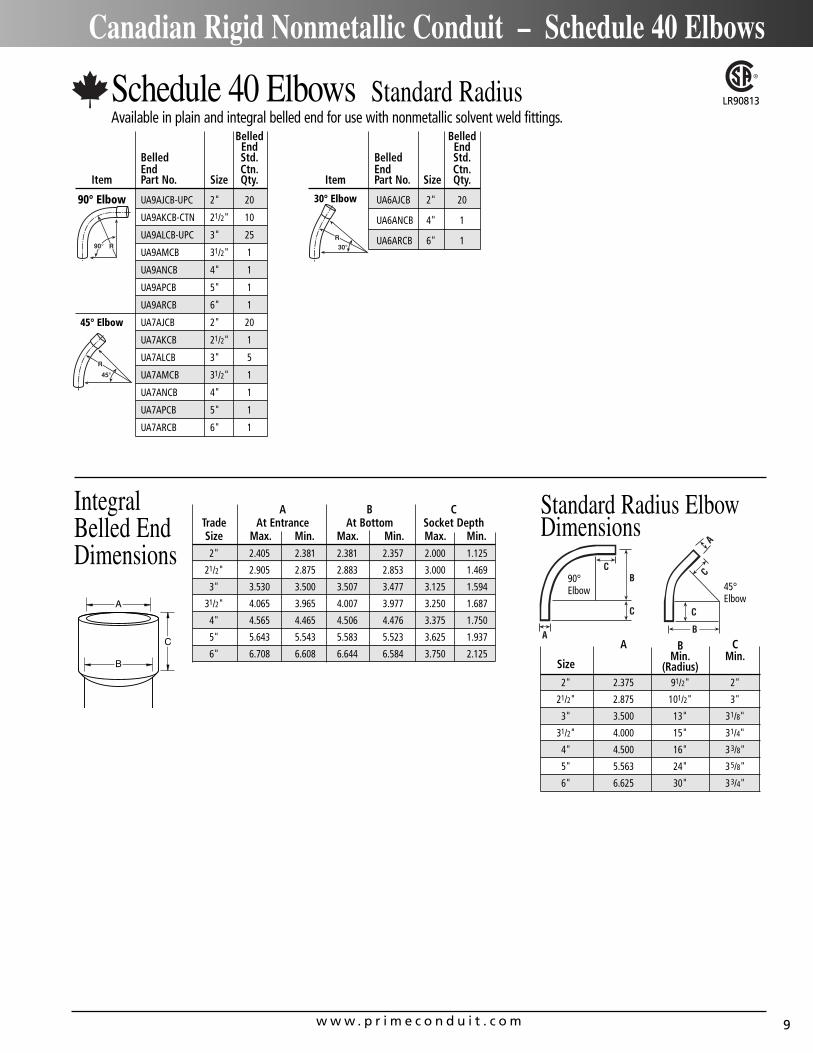
Schedule 40 Elbows Standard Radius Available in plain and integral belled end for use with nonmetallic solvent weld fittings.
A B CMin. Min.
Size (Radius)2" 2.375 91/2" 2"
21/2" 2.875 101/2" 3"
3" 3.500 13" 31/8"
31/2" 4.000 15" 31/4"
4" 4.500 16" 33/8"
5" 5.563 24" 35/8"
6" 6.625 30" 33/4"
A B CTrade At Entrance At Bottom Socket DepthSize Max. Min. Max. Min. Max. Min.2" 2.405 2.381 2.381 2.357 2.000 1.125
21/2" 2.905 2.875 2.883 2.853 3.000 1.469
3" 3.530 3.500 3.507 3.477 3.125 1.594
31/2" 4.065 3.965 4.007 3.977 3.250 1.687
4" 4.565 4.465 4.506 4.476 3.375 1.750
5" 5.643 5.543 5.583 5.523 3.625 1.937
6" 6.708 6.608 6.644 6.584 3.750 2.125
Standard Radius ElbowDimensions
A
C
B
IntegralBelled EndDimensions
LR90813
BelledEnd
Belled Std.End Ctn.
Item Part No. Size Qty.
30° Elbow UA6AJCB 2" 20
UA6ANCB 4" 1
UA6ARCB 6" 1
90°Elbow 45°
Elbow
w w w . p r i m e c o n d u i t . c o m10
Rigid Nonmetallic Conduit
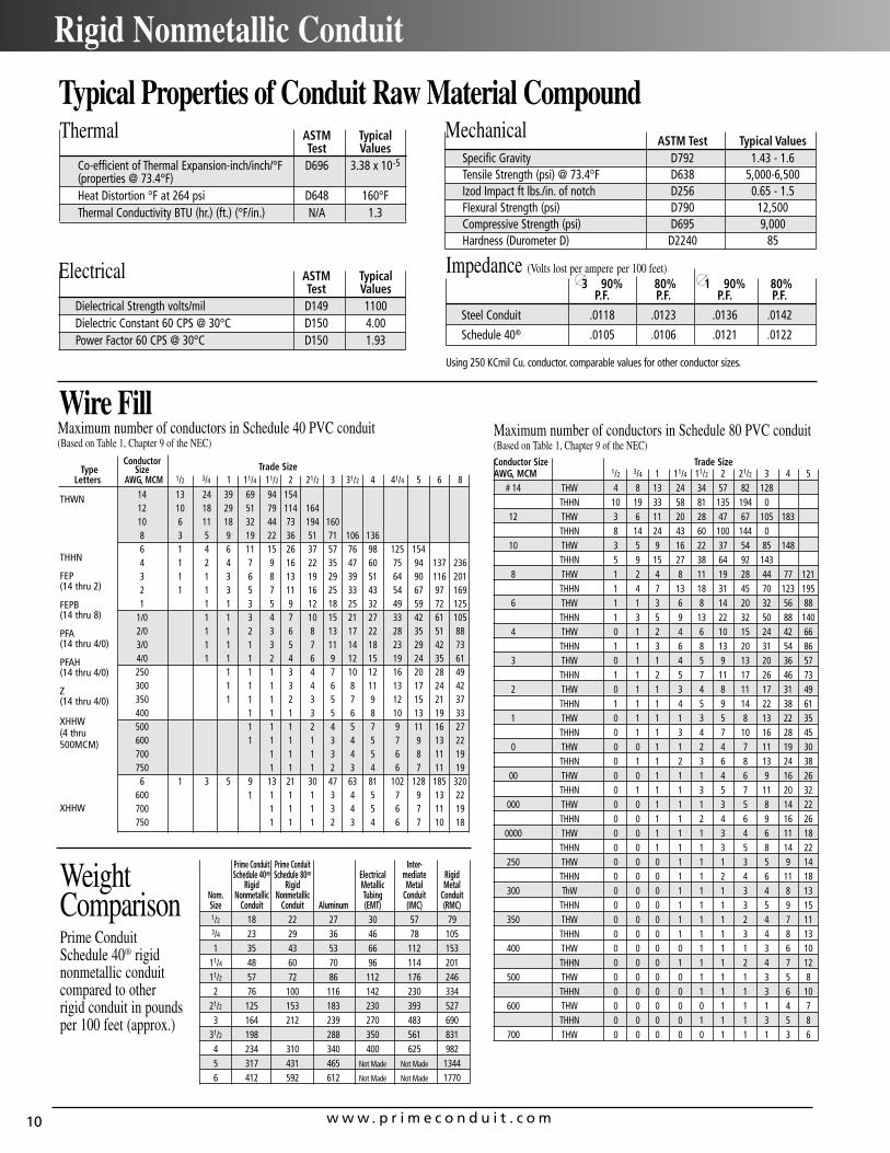
Typical Properties of Conduit Raw Material Compound
Wire FillConductor
Type Size Trade SizeLetters AWG, MCM 1/2 3/4 1 11/4 11/2 2 21/2 3 31/2 4 41/4 5 6 8
14 13 24 39 69 94 15412 10 18 29 51 79 114 16410 6 11 18 32 44 73 194 1608 3 5 9 19 22 36 51 71 106 1366 1 4 6 11 15 26 37 57 76 98 125 1544 1 2 4 7 9 16 22 35 47 60 75 94 137 2363 1 1 3 6 8 13 19 29 39 51 64 90 116 2012 1 1 3 5 7 11 16 25 33 43 54 67 97 1691 1 1 3 5 9 12 18 25 32 49 59 72 125
1/0 1 1 3 4 7 10 15 21 27 33 42 61 1052/0 1 1 2 3 6 8 13 17 22 28 35 51 883/0 1 1 1 3 5 7 11 14 18 23 29 42 734/0 1 1 1 2 4 6 9 12 15 19 24 35 61250 1 1 1 3 4 7 10 12 16 20 28 49300 1 1 1 3 4 6 8 11 13 17 24 42350 1 1 1 2 3 5 7 9 12 15 21 37400 1 1 1 3 5 6 8 10 13 19 33500 1 1 1 2 4 5 7 9 11 16 27600 1 1 1 1 3 4 5 7 9 13 22700 1 1 1 3 4 5 6 8 11 19750 1 1 1 2 3 4 6 7 11 19
6 1 3 5 9 13 21 30 47 63 81 102 128 185 320600 1 1 1 1 3 4 5 7 9 13 22700 1 1 1 3 4 5 6 7 11 19750 1 1 1 2 3 4 6 7 10 18
Thermal ASTM Typical Test Values
Co-efficient of Thermal Expansion-inch/inch/°F D696 3.38 x 10⁻⁵
(properties @ 73.4°F)Heat Distortion °F at 264 psi D648 160°FThermal Conductivity BTU (hr.) (ft.) (°F/in.) N/A 1.3
Electrical ASTM Typical Test Values
Dielectrical Strength volts/mil D149 1100Dielectric Constant 60 CPS @ 30°C D150 4.00Power Factor 60 CPS @ 30°C D150 1.93
MechanicalASTM Test Typical Values
Specific Gravity D792 1.43 - 1.6Tensile Strength (psi) @ 73.4°F D638 5,000-6,500Izod Impact ft lbs./in. of notch D256 0.65 - 1.5Flexural Strength (psi) D790 12,500Compressive Strength (psi) D695 9,000Hardness (Durometer D) D2240 85
Impedance (Volts lost per ampere per 100 feet)3 90% 80% 1 90% 80%
P.F. P.F. P.F. P.F.
Steel Conduit .0118 .0123 .0136 .0142
Schedule 40® .0105 .0106 .0121 .0122
Using 250 KCmil Cu. conductor. comparable values for other conductor sizes.
THWN
THHN
FEP (14 thru 2)
FEPB (14 thru 8)
PFA (14 thru 4/0)
PFAH (14 thru 4/0)
Z(14 thru 4/0)
XHHW(4 thru500MCM)
XHHW
Maximum number of conductors in Schedule 80 PVC conduit (Based on Table 1, Chapter 9 of the NEC)Conductor Size Trade SizeAWG, MCM 1/2 3/4 1 11/4 11/2 2 21/2 3 4 5
# 14 THW 4 8 13 24 34 57 82 128THHN 10 19 33 58 81 135 194 0
12 THW 3 6 11 20 28 47 67 105 183THHN 8 14 24 43 60 100 144 0
10 THW 3 5 9 16 22 37 54 85 148THHN 5 9 15 27 38 64 92 143
8 THW 1 2 4 8 11 19 28 44 77 121THHN 1 4 7 13 18 31 45 70 123 195
6 THW 1 1 3 6 8 14 20 32 56 88THHN 1 3 5 9 13 22 32 50 88 140
4 THW 0 1 2 4 6 10 15 24 42 66THHN 1 1 3 6 8 13 20 31 54 86
3 THW 0 1 1 4 5 9 13 20 36 57THHN 1 1 2 5 7 11 17 26 46 73
2 THW 0 1 1 3 4 8 11 17 31 49THHN 1 1 1 4 5 9 14 22 38 61
1 THW 0 1 1 1 3 5 8 13 22 35THHN 0 1 1 3 4 7 10 16 28 45
0 THW 0 0 1 1 2 4 7 11 19 30THHN 0 1 1 2 3 6 8 13 24 38
00 THW 0 0 1 1 1 4 6 9 16 26THHN 0 1 1 1 3 5 7 11 20 32
000 THW 0 0 1 1 1 3 5 8 14 22THHN 0 0 1 1 2 4 6 9 16 26
0000 THW 0 0 1 1 1 3 4 6 11 18THHN 0 0 1 1 1 3 5 8 14 22
250 THW 0 0 0 1 1 1 3 5 9 14THHN 0 0 0 1 1 2 4 6 11 18
300 ThW 0 0 0 1 1 1 3 4 8 13THHN 0 0 0 1 1 1 3 5 9 15
350 THW 0 0 0 1 1 1 2 4 7 11THHN 0 0 0 1 1 1 3 4 8 13
400 THW 0 0 0 0 1 1 1 3 6 10THHN 0 0 0 1 1 1 2 4 7 12
500 THW 0 0 0 0 1 1 1 3 5 8THHN 0 0 0 0 1 1 1 3 6 10
600 THW 0 0 0 0 0 1 1 1 4 7THHN 0 0 0 0 1 1 1 3 5 8
700 THW 0 0 0 0 0 1 1 1 3 6
Prime Conduit Prime Conduit Inter-Schedule 40® Schedule 80® Electrical mediate Rigid
Rigid Rigid Metallic Metal MetalNom. Nonmetallic Nonmetallic Tubing Conduit ConduitSize Conduit Conduit Aluminum (EMT) (IMC) (RMC)1/2 18 22 27 30 57 793/4 23 29 36 46 78 1051 35 43 53 66 112 153
11/4 48 60 70 96 114 20111/2 57 72 86 112 176 2462 76 100 116 142 230 334
21/2 125 153 183 230 393 5273 164 212 239 270 483 690
31/2 198 288 350 561 8314 234 310 340 400 625 9825 317 431 465 Not Made Not Made 13446 412 592 612 Not Made Not Made 1770
WeightComparisonPrime ConduitSchedule 40® rigidnonmetallic conduitcompared to otherrigid conduit in poundsper 100 feet (approx.)
Maximum number of conductors in Schedule 40 PVC conduit (Based on Table 1, Chapter 9 of the NEC)
w w w . p r i m e c o n d u i t . c o m 11
Rigid Nonmetallic Conduit – Expansion and Contraction
Temperature Considerations for RigidNonmetallic Conduit Compensationfor Linear Expansion
Expansion and Contraction
Like all construction materials, PVC will expand or contract with variations in temperatures. The coefficient of linear expansion in PVCconduit is 3.38 x 10⁻⁵ in./in./°F as compared to 1.2 x 10⁻⁵ for aluminumand 0.6 x 10⁻⁵ for steel. An expansion fitting is needed whenever thechange in length due to temperature variation will be 1/4 in orgreater per 352.44 of the NEC.
Add 30°F to the estimated temperature range when conduit isinstalled in direct sunlight to allow for radiant heating.
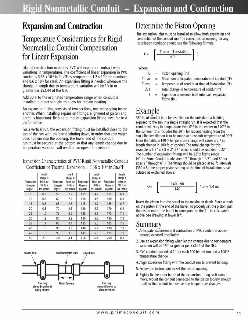
An expansion fitting consists of two sections, one telescoping insideanother. When installing expansion fittings, alignment of piston andbarrel is important. Be sure to mount expansion fitting level for bestperformance.
For a vertical run, the expansion fitting must be installed close to thetop of the run with the barrel jointing down, in order that rain waterdoes not run into the opening. The lower end of the conduit run must be secured at the bottom so that any length change due totemperature variation will result in an upward movement.
Expansion Characteristics of PVC Rigid Nonmetallic ConduitCoefficient of Thermal Expansion = 3.38 x 10⁻⁵ in./in./°F
Length Length Length Length Change in Change in Change in Change in
Temperature inches per Temperature inches per Temperature inches per Temperature inches perChange in 100 Ft. of Change in 100 Ft. of Change in 100 Ft. of Change in 100 Ft. ofDegrees F PVC Conduit Degrees F PVC Conduit Degrees F PVC Conduit Degrees F PVC Conduit
5 0.2 55 2.2 105 4.2 155 6.3
10 0.4 60 2.4 110 4.5 160 6.5
15 0.6 65 2.6 115 4.7 165 6.7
20 0.8 70 2.8 120 4.9 170 6.9
25 1.0 75 3.0 125 5.1 175 7.1
30 1.2 80 3.2 130 5.3 180 7.3
35 1.4 85 3.4 135 5.5 185 7.5
40 1.6 90 3.6 140 5.7 190 7.7
45 1.8 95 3.8 145 5.9 195 7.9
50 2.0 100 4.1 150 6.1 200 8.1
The expansion joint must be installed to allow both expansion andcontraction of the conduit run. The correct piston opening for anyinstallation condition should use the following formula:
Determine the Piston Opening
O= ET max - T installedT[ ]
Where:O = Piston opening (in.)
T max = Maximum anticipated temperature of conduit (°F)T inst. = Temperature of conduit at time of installation (°F)
T = Total change in temperature of conduit (°F)E = Expansion allowance built into each expansion
fitting (in.)
380 ft. of conduit is to be installed on the outside of a buildingexposed to the sun in a single straight run. It is expected that theconduit will vary in temperature from 0°F in the winter to 140°F inthe summer (this includes the 30°F for radiant heating from thesun.) The installation is to be made at a conduit temperature of 90°F.From the table, a 140°F temperature change will cause a 5.7 in.length change in 100 ft. of conduit. The total change for this example is 5.7" x 3.8 = 21.67" which should be rounded to 22".The number of expansion fittings will be 22"x fitting range (4" for Prime Conduit trade sizes 1/2" through 1-1/2", and 8" forsizes 2" through 6".) The fitting should be placed at 62 ft. intervals(380 x 6). the proper piston setting at the time of installation is cal-culated as explained above.
Example
O= 4.0 = 1.4 in.140 - 90140[ ]
Insert the piston into the barrel to the maximum depth. Place a markon the piston at the end of the barrel. To properly set the piston, pullthe piston out of the barrel to correspond to the 2.1 in. calculatedabove. See drawing at lower left.
Summary1. Anticipate expansion and contraction of PVC conduit in above-
ground, exposed installation.
2. Use an expansion fitting when length change due to temperaturevariation will be 1/4" or greater per 352.44 of the NEC.
3. PVC conduit expands 4.1" for each 100 feet of run and a 100°Ftemperature change.
4. Align expansion fitting with the conduit run to prevent binding.
5. Follow the instructions to set the piston opening.
6. Rigidly fix the outer barrel of the expansion fitting so it cannotmove. Mount the conduit connected to the piston loosely enoughto allow the conduit to move as the temperature changes.
Solvent Weld Solvent WeldMaximum Depth Mark
Piston OpeningPipe strap should be anchored
tightly to barrel
Pipe strap mounted loosely to
allow movement
w w w . p r i m e c o n d u i t . c o m12
Rigid Nonmetallic Conduit
Corrosion Resistance of Prime Conduit Schedule 40 and Schedule 80 PVC ConduitPrime Conduit Schedule 40 and Schedule 80 are generally acceptable for use in environments containing the chemicalsbelow. These environmental resistance ratings are basedupon tests where the specimens were placed in completesubmergence in the reagent listed. Schedule 40 andSchedule 80 can be used in many process areas where
chemicals not on this list are manufactured or used becauseworker safety requirements dictate that any air presence orsplashing be at a very low level.
If there are any questions for specific suitability in agiven environment, prototype samples should be tested under actual conditions.
Acetic Acid O-20%Acetic Acid 20-30%Acetic Acid 3O-60%Acetic Acid 80%Acetic Acid – GlacialAcetic Acid VaporsAcetyleneAdipic AcidAlumAluminum ChlorideAluminum FluorideAluminum HydroxideAluminum OxychlorideAluminum NitrateAluminum SulfateAmmonia-Dry GasAmmonium BifluorideAmmonium CarbonateAmmonium ChlorideAmmonium Hydroxide 28%Ammonium MetaphosphateAmmonium NitrateAmmonium PersulfateAmmonium Phosphate – NeutralAmmonium SulfateAmmonium SulfideAmmonium ThiocyanateAmyl AlcoholAnthraquinoneAnthraquinonesulfonic AcidAntimony TrichlorideAqua RegiaArsenic Acid 80%Arylsulfonic AcidBarium CarbonateBarium ChlorideBarium HydroxideBarium SulfateBarium SulfideBeet – Sugar LiquorBenzine Sulfonic Acid 10%Benzoic AcidBismuth CarbonateBlack Liquor (Paper Industry)Bleach – 12.5% Active CL2
BoraxBoric AcidBrineBreeder Pellets – Dane. FishBromic AcidBromine – WaterButaneButadiene
Butyl AlcoholButyl PhenolButyleneButyric AcidCalcium BisulfiteCalcium CarbonateCalcium ChlorateCalcium ChlorideCalcium HydroxideCalcium HypochloriteCalcium NitrateCalcium SulfateCarbonic AcidCarbon Dioxide Gas – WetCarbon Dioxide – AqueousSolutionCarbon MonoxideCaustic PotashCaustic SodaChloracatic AcidChloral HydrateChlorine Gas (Dry)Chlorine Gas (Moist)Chlorine WaterChlorosulfonic AcidChrome AlumChromic Acid 10%Chromic Acid 30%Chromic Acid 40%Chromic Acid 50%Citric AcidCopper ChlorideCopper CyanideCopper FluorideCopper NitrateCopper SulfateCottonseed OilCresylic Acid 50%Crude Oil – SourCrude Oil – SweetDemineralized WaterDextrinDextroseDiglycolic AcidDisodium PhosphateEthyl AlcoholEthylene GlycolFatty AcidsFerric ChlorideFerric NitrateFerric SulfateFerrous ChlorideFerrous Sulfate
Fluorine Gas – WetFluorine Gas – DryFluoroboric AcidFluorosilicic AcidFormaldehydeFormic AcidFructoseGallic AcidGas – Coke OvenGas – Natural (Dry)Gas – Natural (Wet)Gasoline – SourGasoline – RefinedGlucoseGlycerine (Glycerol)GlycolGlycolic AcidGreen Liquor (Paper Industry)HeptaneHexanol, TertiaryHydrobromic Acid 20%Hydrochloric Acid 0% - 25%Hydrochloric Acid 25% - 40%Hydrocyanic Acid or
Hydrogen CyanideHydrofluoric Acid 10%Hydrofluorosilicic AcidHydrogen PhosphideHydrogen Sulfide – DryHydrogen Sulfide –
Aqueous SolutionHydroquinoneHydroxylamine SulfateIodineKeroseneLactic Acid 28%Lauric AcidLauryl ChlorideLauryl SulfateLead AcetateLime SulfurLinoleic AcidLinseed OilLubricating OilsMagnesium CarbonateMagnesium ChlorideMagnesium HydroxideMagnesium NitrateMagnesium SulfateMaleic AcidMalic AcidMercuric ChlorideMercuric Cyanide
Mercurous NitrateMercuryMethyl SulfateMethylene ChlorideMineral OilsNaphthaleneNickel ChlorideNickel NitrateNitric Acid, AnydrousNitric Acid 20%Nitric Acid 40%Nitric Acid 60%NitrobenzeneNitrous OxideOils and FatsOils – Petroleum – (See Type)Oleic AcidOxalic AcidPalmitic Acid 10%Perchloric Acid 10%Phenylhydrazine HydrochloridePhosgene, GasPhosphoric Acid – 0-25%Phosphoric Acid – 25-50%Phosphoric Acid – 50-85%Photographic ChemicalsPlating SolutionsPotassium BicarbonatePotassium BichromatePotassium BoratePotassium BromidePotassium CarbonatePotassium ChloridePotassium ChromatePotassium CyanidePotassium DichromatePotassium FerricyanidePotassium FerrocyanidePotassium FluoridePotassium HydroxidePotassium NitratePotassium PerboratePotassium PerchloritePotassium Permanganate 10%Potassium PersulfatePotassium SulfatePropanePropyl AlcoholSilicic AcidSilver CyanideSilver NitrateSilver Plating SolutionsSodium Acetate
Sodium ArseniteSodium BenzoateSodium BicarbonateSodium BisulfateSodium BisulfiteSodium BromideSodium ChlorateSodium ChlorideSodium CyanideSodium DichromateSodium FerricyanideSodium FerrocyanideSodium FluorideSodium HydroxideSodium HypochloriteSodium NitrateSodium NitriteSodium SulfateSodium SulfideSodium SulfiteSodium Thiosulfate (Hypo)Stannic ChlorideStannous ChlorideStearic AcidSulfurSulfur Dioxide – Gas DrySulfur TrioxideSulfuric Acid – 0-10%Sulfuric Acid – 10-75%Sulfuric Acid – 75-90%Sulfurous AcidTannic AcidTanning LiquorsTartaric AcidTitanium TetrachlorideTriethanolamineTrimethyl PropaneTrisodium PhosphateTurpentineUreaVinegarWhiskeyWhite Liquor (Paper Industry)WinesZinc ChlorideZinc ChromateZinc CyanideZinc NitrateZinc Sulfate
w w w . p r i m e c o n d u i t . c o m 13
Rigid Nonmetallic Conduit – Specification Format
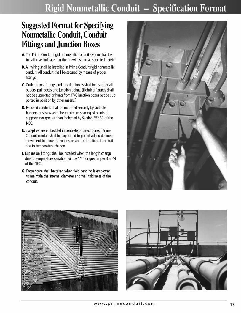
A. The Prime Conduit rigid nonmetallic conduit system shall beinstalled as indicated on the drawings and as specified herein.
B. All wiring shall be installed in Prime Conduit rigid nonmetallicconduit. All conduit shall be secured by means of proper fittings.
C. Outlet boxes, fittings and junction boxes shall be used for alloutlets, pull boxes and junction points. (Lighting fixtures shallnot be supported or hung from PVC junction boxes but be sup-ported in position by other means.)
D. Exposed conduits shall be mounted securely by suitable hangers or straps with the maximum spacing of points of supports not greater than indicated by Section 352.30 of theNEC.
E. Except where embedded in concrete or direct buried, PrimeConduit conduit shall be supported to permit adequate lineal movement to allow for expansion and contraction of conduitdue to temperature change.
F. Expansion fittings shall be installed when the length changedue to temperature variation will be 1/4" or greater per 352.44of the NEC.
G. Proper care shall be taken when field bending is employed to maintain the internal diameter and wall thickness of theconduit.
Suggested Format for SpecifyingNonmetallic Conduit, ConduitFittings and Junction Boxes
w w w . p r i m e c o n d u i t . c o m14
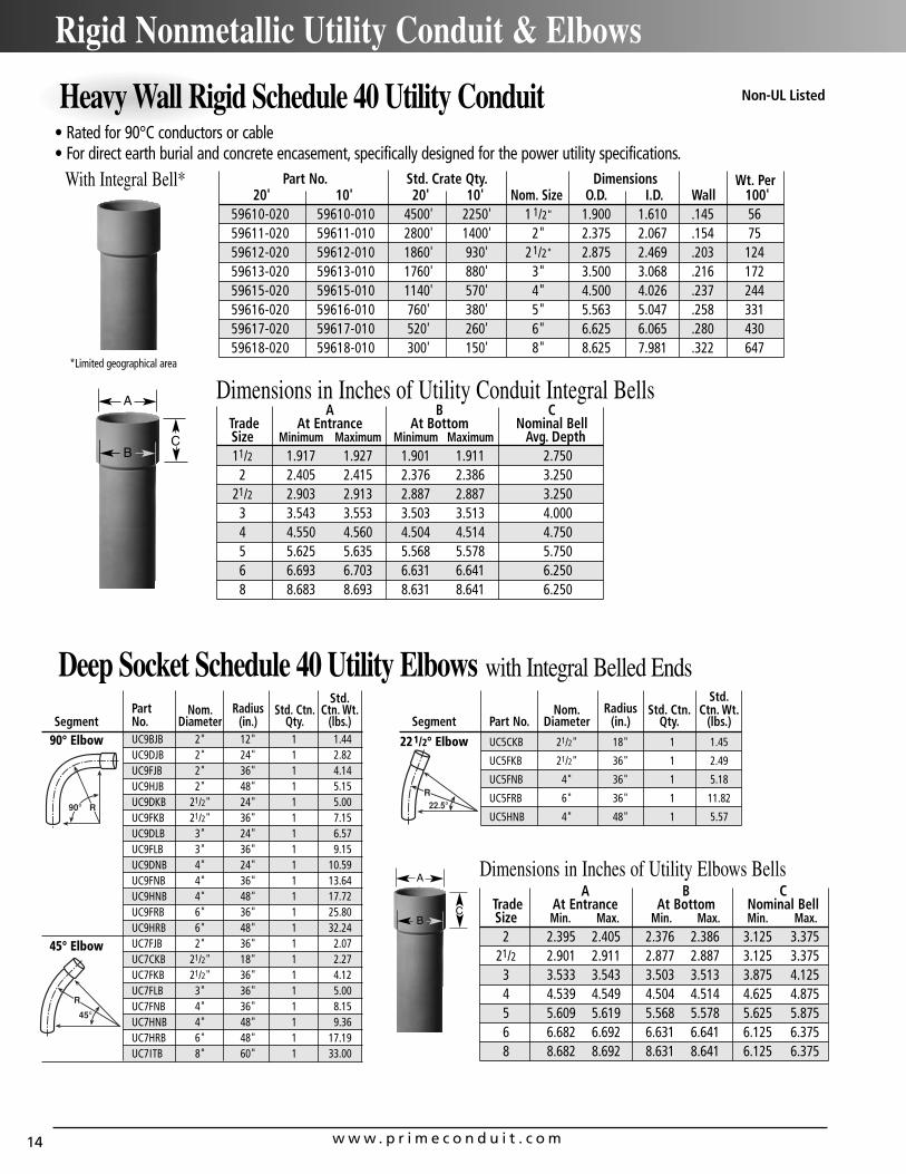
Rigid Nonmetallic Utility Conduit & Elbows
Part No. Std. Crate Qty. Dimensions Wt. Per20' 10' 20' 10' Nom. Size O.D. I.D. Wall 100'
59610-020 59610-010 4500' 2250' 1 1/2" 1.900 1.610 .145 5659611-020 59611-010 2800' 1400' 2" 2.375 2.067 .154 7559612-020 59612-010 1860' 930' 21/2" 2.875 2.469 .203 12459613-020 59613-010 1760' 880' 3" 3.500 3.068 .216 17259615-020 59615-010 1140' 570' 4" 4.500 4.026 .237 24459616-020 59616-010 760' 380' 5" 5.563 5.047 .258 33159617-020 59617-010 520' 260' 6" 6.625 6.065 .280 43059618-020 59618-010 300' 150' 8" 8.625 7.981 .322 647
• Rated for 90°C conductors or cable• For direct earth burial and concrete encasement, specifically designed for the power utility specifications.
With Integral Bell*
*Limited geographical area
A B CTrade At Entrance At Bottom Nominal BellSize Minimum Maximum Minimum Maximum Avg. Depth11/2 1.917 1.927 1.901 1.911 2.750
2 2.405 2.415 2.376 2.386 3.25021/2 2.903 2.913 2.887 2.887 3.250
3 3.543 3.553 3.503 3.513 4.0004 4.550 4.560 4.504 4.514 4.7505 5.625 5.635 5.568 5.578 5.7506 6.693 6.703 6.631 6.641 6.2508 8.683 8.693 8.631 8.641 6.250
Non-UL Listed
Dimensions in Inches of Utility Conduit Integral BellsA
BC
Heavy Wall Rigid Schedule 40 Utility Conduit
Deep Socket Schedule 40 Utility Elbows with Integral Belled EndsStd.
Part Nom. Radius Std. Ctn. Ctn. Wt.Segment No. Diameter (in.) Qty. (lbs.)
90° Elbow UC9BJB 2" 12" 1 1.44UC9DJB 2" 24" 1 2.82UC9FJB 2" 36" 1 4.14UC9HJB 2" 48" 1 5.15UC9DKB 21/2" 24" 1 5.00UC9FKB 21/2" 36" 1 7.15UC9DLB 3" 24" 1 6.57UC9FLB 3" 36" 1 9.15UC9DNB 4" 24" 1 10.59UC9FNB 4" 36" 1 13.64UC9HNB 4" 48" 1 17.72UC9FRB 6" 36" 1 25.80UC9HRB 6" 48" 1 32.24
45° Elbow UC7FJB 2" 36" 1 2.07UC7CKB 21/2" 18" 1 2.27UC7FKB 21/2" 36" 1 4.12UC7FLB 3" 36" 1 5.00UC7FNB 4" 36" 1 8.15UC7HNB 4" 48" 1 9.36UC7HRB 6" 48" 1 17.19UC7ITB 8" 60" 1 33.00
Std.Nom. Radius Std. Ctn. Ctn. Wt.
Segment Part No. Diameter (in.) Qty. (lbs.)
221/2° Elbow UC5CKB 21/2" 18" 1 1.45
UC5FKB 21/2" 36" 1 2.49
UC5FNB 4" 36" 1 5.18
UC5FRB 6" 36" 1 11.82
UC5HNB 4" 48" 1 5.57
A B CTrade At Entrance At Bottom Nominal BellSize Min. Max. Min. Max. Min. Max.
2 2.395 2.405 2.376 2.386 3.125 3.37521/2 2.901 2.911 2.877 2.887 3.125 3.375
3 3.533 3.543 3.503 3.513 3.875 4.1254 4.539 4.549 4.504 4.514 4.625 4.8755 5.609 5.619 5.568 5.578 5.625 5.8756 6.682 6.692 6.631 6.641 6.125 6.3758 8.682 8.692 8.631 8.641 6.125 6.375
Dimensions in Inches of Utility Elbows BellsA
BC
w w w . p r i m e c o n d u i t . c o m 15
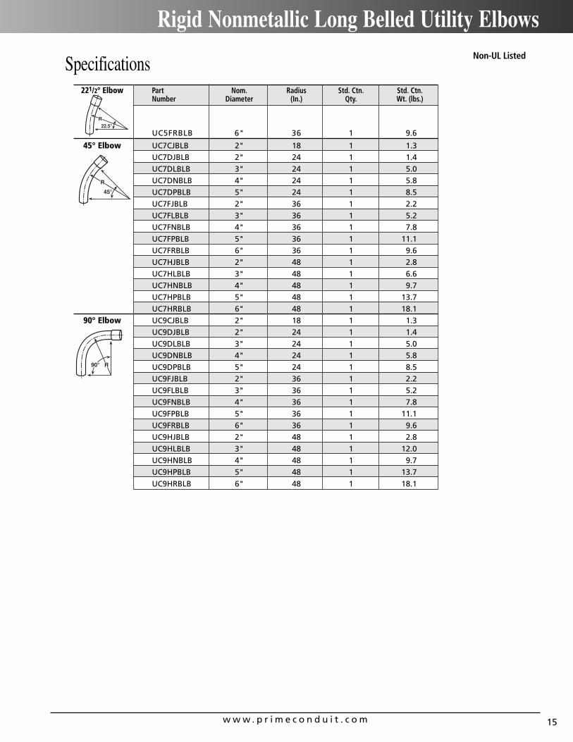
Rigid Nonmetallic Long Belled Utility Elbows
Specifications221/2° Elbow Part Nom. Radius Std. Ctn. Std. Ctn.
Number Diameter (In.) Qty. Wt. (lbs.)
UC5FRBLB 6" 36 1 9.6
45° Elbow UC7CJBLB 2" 18 1 1.3
UC7DJBLB 2" 24 1 1.4
UC7DLBLB 3" 24 1 5.0
UC7DNBLB 4" 24 1 5.8
UC7DPBLB 5" 24 1 8.5
UC7FJBLB 2" 36 1 2.2
UC7FLBLB 3" 36 1 5.2
UC7FNBLB 4" 36 1 7.8
UC7FPBLB 5" 36 1 11.1
UC7FRBLB 6" 36 1 9.6
UC7HJBLB 2" 48 1 2.8
UC7HLBLB 3" 48 1 6.6
UC7HNBLB 4" 48 1 9.7
UC7HPBLB 5" 48 1 13.7
UC7HRBLB 6" 48 1 18.1
90° Elbow UC9CJBLB 2" 18 1 1.3
UC9DJBLB 2" 24 1 1.4
UC9DLBLB 3" 24 1 5.0
UC9DNBLB 4" 24 1 5.8
UC9DPBLB 5" 24 1 8.5
UC9FJBLB 2" 36 1 2.2
UC9FLBLB 3" 36 1 5.2
UC9FNBLB 4" 36 1 7.8
UC9FPBLB 5" 36 1 11.1
UC9FRBLB 6" 36 1 9.6
UC9HJBLB 2" 48 1 2.8
UC9HLBLB 3" 48 1 12.0
UC9HNBLB 4" 48 1 9.7
UC9HPBLB 5" 48 1 13.7
UC9HRBLB 6" 48 1 18.1
Non-UL Listed