Embed Size (px)
Citation preview
I.N.G. Fixations - ZI de Chassende BP 90168 Tél: +33 (0)4 71 05 59 03 - Fax: +33 (0)4 71 09 35 46
EVALUATION
RÉSINE VINYLESTER SANS STYRÈNE 300 ml MP+ - 410 ml MP+
Scellement de tiges filetées et armatures dans le béton
ZI de Chassende BP 90168 43005 Le Puy en Velay cedex France Fax: +33 (0)4 71 09 35 46 - [email protected] - www.ingfixations.fr
EVALUATION TECHNIQUE EUROPÉEN
ETE - 16/0838
RÉSINE VINYLESTER SANS STYRÈNE 410 ml MP+ - 300 ml MP+ TROPICALE
Scellement de tiges filetées et armatures dans le béton fissuré et non fissuré
www.ingfixations.fr
TECHNIQUE EUROPÉENNE
RÉSINE VINYLESTER SANS STYRÈNE 300 ml MP+ TROPICALE
Scellement de tiges filetées et armatures dans non fissuré
Membre Adhérent n° 586
Technical and Test Institute for Construction Prague Prosecká 811/76a 190 00 Prague Czech Republic [email protected]
Member of
www.eota.eu
ETA 16/0838 of 31/10/2016 – Page 1 of 23 090-036807
European Technical Assessment
ETA 16/0838 of 31/10/2016
Technical Assessment Body issuing the ETA: Technical and Test Institute for Construction Prague Trade name of the construction product ING MP+, ING MP+ Tropical
Product family to which the construction product belongs
Product area code: 33 Bonded injection type anchor for use in cracked and non-cracked concrete
Manufacturer
I.N.G. Fixations BP168 Z l de Chassende 43005 Le Puy-en-Velay Cedex France
Manufacturing plant Usine 1
This European Technical Assessment contains
23 pages including 19 Annexes which form an integral part of this assessment.
This European Technical Assessment is issued in accordance with regulation (EU) No 305/2011, on the basis of
ETAG 001-Part 1 and Part 5, edition 2013, used as European Assessment Document (EAD)
Translations of this European Technical Assessment in other languages shall fully correspond to the original issued document and should be identified as such. Communication of this European Technical Assessment, including transmission by electronic means, shall be in full (excepted the confidential Annex(es) referred to above). However, partial reproduction may be made, with the written consent of the issuing Technical Assessment Body - Technical and Test Institute for Construction Prague. Any partial reproduction has to be identified as such.
Page 2 of 23 ETA 16/0838 issued on 31/10/2016
1. Technical description of the product
The ING MP+ and ING MP+ Tropical (extended processing time) with steel elements is bonded anchor (injection type).
Steel elements can be galvanized or stainless steel threaded rod or rebar.
Steel element is placed into a drilled hole filled with injection mortar. The steel element is anchored via the bond between metal part, injection mortar and concrete. The anchor is intended to be used with embedment depth from 8 diameters to 20 diameters. The illustration and the description of the product are given in Annex A.
2. Specification of the intended use in accordance wit h the applicable EAD
The performances given in Section 3 are only valid if the anchor is used in compliance with the specifications and conditions given in Annex B.
The provisions made in this European Technical Assessment are based on an assumed working life of the anchor of 50 years. The indications given on the working life cannot be interpreted as a guarantee given by the producer, but are to be regarded only as a means for choosing the products in relation to the expected economically reasonable working life of the works.
3. Performance of the product and references to the me thods used for its assessment
3.1 Mechanical resistance and stability (BWR 1) Essential characteristic Performance Characteristic resistance for tension loads - threaded rod See Annex C 1 Characteristic resistance for tension loads - rebar See Annex C 2 Characteristic resistance for shear loads - threaded rod See Annex C 3 Characteristic resistance for shear loads - rebar See Annex C 4 Characteristic resistance for tension loads - threaded rod See Annex C 5 Characteristic resistance for tension loads - rebar See Annex C 6 Characteristic resistance for shear loads - threaded rod See Annex C 7 Characteristic resistance for shear loads - rebar See Annex C 8 Displacement for threaded rod See Annex C 9 Displacement for rebar See Annex C 10 Characteristic resistance for tension and shear loads for seismic design - threaded rod See Annex C 11
3.2 Safety in case of fire (BWR 2) Essential characteristic Performance Reaction to fire Anchorages satisfy
requirements for Class A1
Resistance to fire No performance assessed
3.3 Hygiene, health and environment (BWR 3)
Regarding dangerous substances contained in this European Technical Assessment, there may be requirements applicable to the products falling within its scope (e.g. transposed European legislation and national laws, regulations and administrative provisions). In order to meet the provisions of the Regulation (EU) No 305/2011, these requirements need also to be complied with, when and where they apply.

Page 3 of 23 ETA 16/0838 issued on 31/10/2016
3.4 Safety in use (BWR 4)
For basic requirement safety in use the same criteria are valid as for Basic Requirement Mechanical resistance and stability.
3.5 Sustainable use of natural resources (BWR 7)
For the sustainable use of natural resources no performance was determined for this product.
3.6 General aspects relating to fitness for use
Durability and serviceability are only ensured if the specifications of intended use according to Annex B 1 are kept.
4. Assessment and verification of constancy of perf ormance (AVCP) system
applied with reference to its legal base
According to the Decision 96/582/EC of the European Commission1 the system of assessment verification of constancy of performance (see Annex V to Regulation (EU) No 305/2011) given in the following table apply. Product Intended use Level or class System Metal anchors for use in concrete
For fixing and/or supporting to concrete, structural elements (which contributes to the stability of the works) or heavy units
- 1
5. Technical details necessary for the implementati on of the AVCP system, as provided in the applicable EAD
5.1 Tasks of the manufacturer
The manufacturer shall exercise permanent internal control of production. All the elements, requirements and provisions adopted by the manufacturer shall be documented in a systematic manner in the form of written policies and procedures, including records of results performed. This production control system shall insure that the product is in conformity with this European Technical Assessment. The manufacturer may only use raw materials stated in the technical documentation of this European Technical Assessment.
The factory production control shall be in accordance with the control plan which is a part of the technical documentation of this European Technical Assessment. The control plan is laid down in the context of the factory production control system operated by the manufacturer and deposited at Technical and Test Institute for Construction Prague.2 The results of factory production control shall be recorded and evaluated in accordance with the provisions of the control plan.
The manufacturer shall, on the basis of a contract, involve a body which is notified for the tasks referred to in section 4 in the field of anchors in order to undertake the actions laid down in section 5.2. For this purpose, the control plan referred to in this section and section 5.2 shall be handed over by the manufacturer to the notified body involved.
The manufacturer shall make a declaration of performance, stating that the construction product is in conformity with the provisions of this European Technical Assessment.
1 Official Journal of the European Communities L 254 of 08.10.1996 2 The control plan is a confidential part of the documentation of the European Technical Assessment, but not
published together with the ETA and only handed over to the approved body involved in the procedure of AVCP.
Page 4 of 23 ETA 16/0838 issued on 31/10/2016
5.2 Tasks of the notified bodies
The notified body shall retain the essential points of its actions referred to above and state the results obtained and conclusions drawn in a written report.
The notified certification body involved by the manufacturer shall issue a certificate of constancy of performance of the product stating the conformity with the provisions of this European Technical Assessment.
In cases where the provisions of the European Technical Assessment and its control plan are no longer fulfilled the notified body shall withdraw the certificate of constancy of performance and inform Technical and Test Institute for Construction Prague without delay.
Issued in Prague on 31.10.2016
By
Ing. Mária Schaan Head of the Technical Assessment Body
Page 5 of 23 ETA 16/0838 issued on 31/10/2016
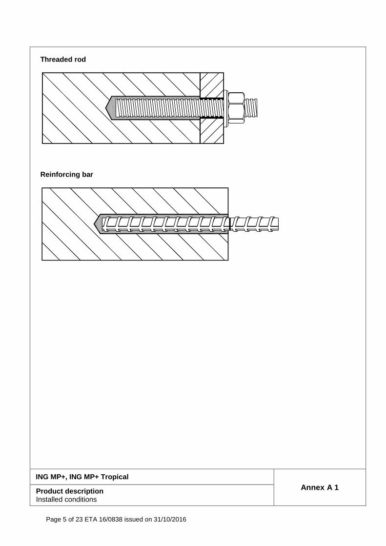
Threaded rod
Reinforcing bar
ING MP+, ING MP+ Tropical
Annex A 1 Product description Installed conditions
Page 6 of 23 ETA 16/0838 issued on 31/10/2016
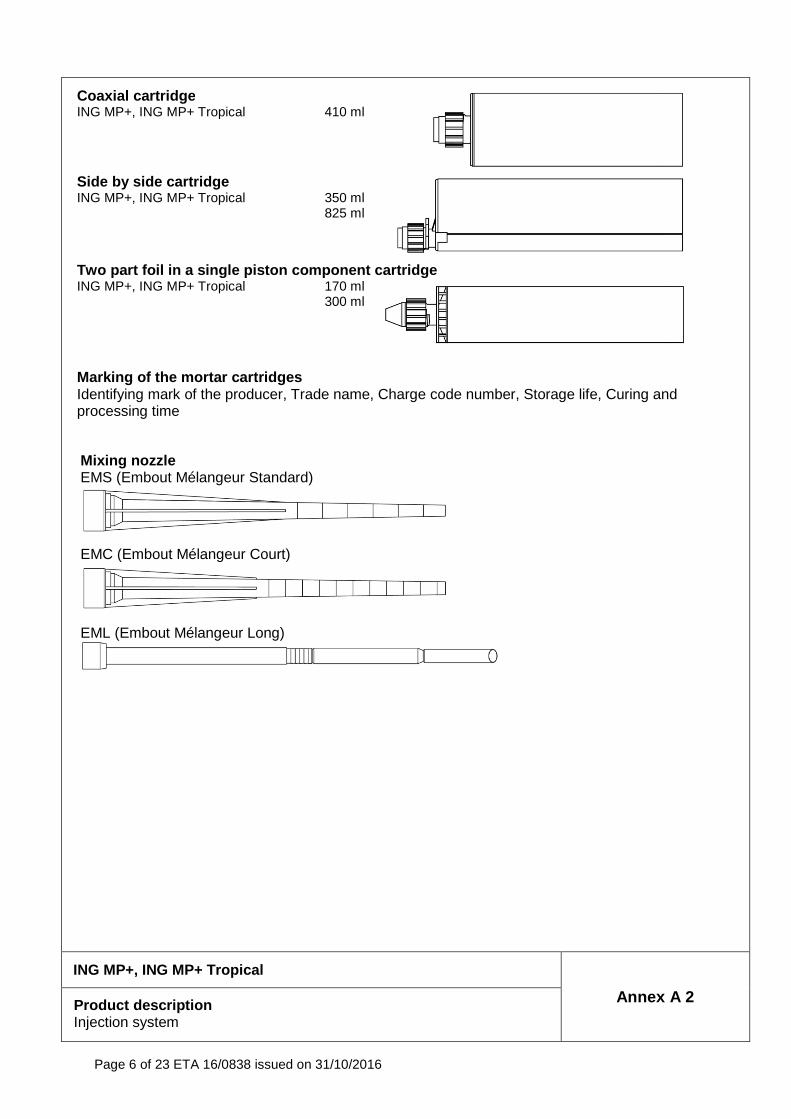
Coaxial cartridge
ING MP+, ING MP+ Tropical 410 ml
Side by side cartridge
ING MP+, ING MP+ Tropical 350 ml 825 ml
Two part foil in a single piston component cartridg e ING MP+, ING MP+ Tropical 170 ml
300 ml
Marking of the mortar cartridges Identifying mark of the producer, Trade name, Charge code number, Storage life, Curing and processing time
Mixing nozzle EMS (Embout Mélangeur Standard)
EMC (Embout Mélangeur Court)
EML (Embout Mélangeur Long)
ING MP+, ING MP+ Tropical
Annex A 2 Product description Injection system
Page 7 of 23 ETA 16/0838 issued on 31/10/2016
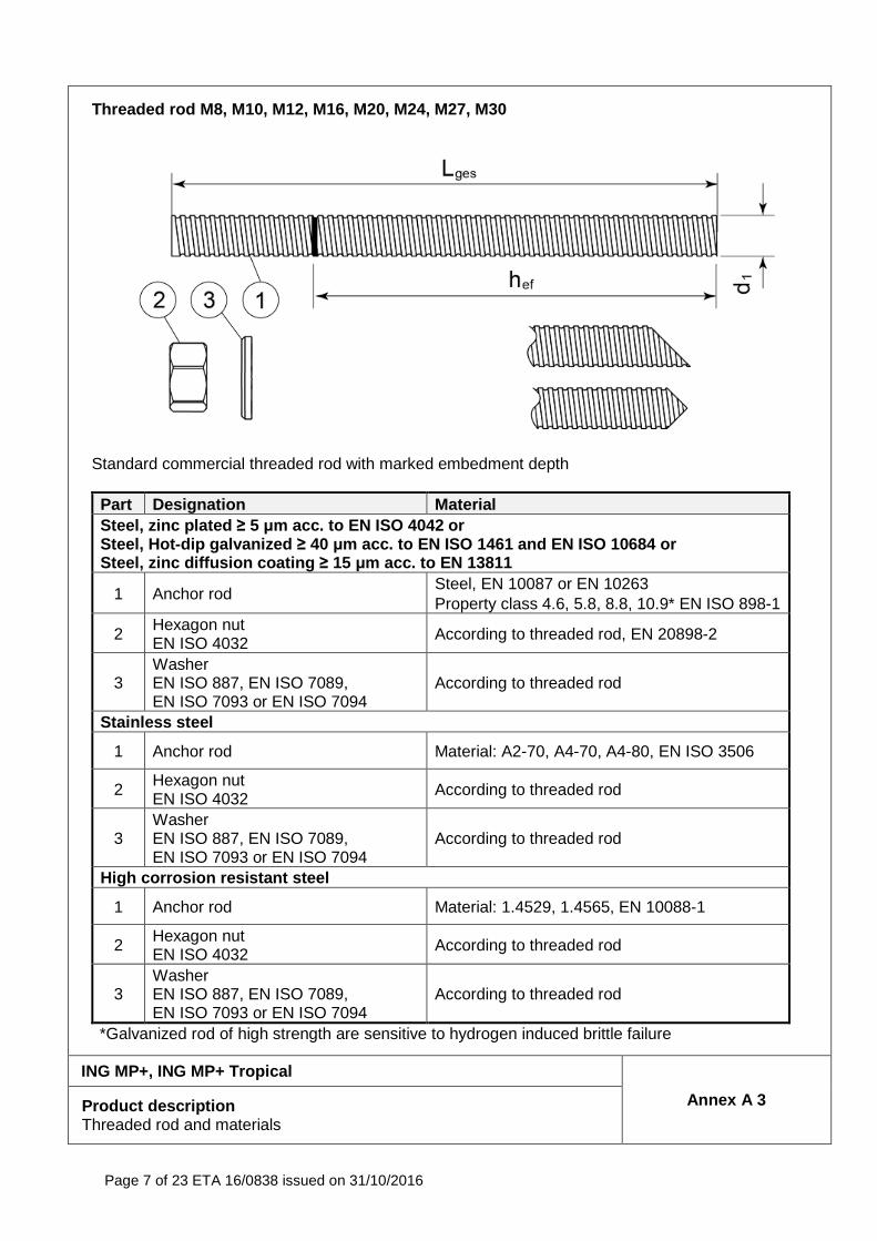
Threaded rod M8, M10, M12, M16, M20, M24, M27, M30
Standard commercial threaded rod with marked embedment depth
Part Designation Material Steel, zinc plated ≥ 5 µm acc. to EN ISO 4042 or Steel, Hot-dip galvanized ≥ 40 µm acc. to EN ISO 1461 and EN ISO 10684 or Steel, zinc diffusion coating ≥ 15 µm acc. to EN 13811
1 Anchor rod Steel, EN 10087 or EN 10263 Property class 4.6, 5.8, 8.8, 10.9* EN ISO 898-1
2 Hexagon nut EN ISO 4032 According to threaded rod, EN 20898-2
3 Washer EN ISO 887, EN ISO 7089, EN ISO 7093 or EN ISO 7094
According to threaded rod
Stainless steel
1 Anchor rod Material: A2-70, A4-70, A4-80, EN ISO 3506
2 Hexagon nut EN ISO 4032 According to threaded rod
3 Washer EN ISO 887, EN ISO 7089, EN ISO 7093 or EN ISO 7094
According to threaded rod
High corrosion resistant steel
1 Anchor rod Material: 1.4529, 1.4565, EN 10088-1
2 Hexagon nut EN ISO 4032 According to threaded rod
3 Washer EN ISO 887, EN ISO 7089, EN ISO 7093 or EN ISO 7094
According to threaded rod
*Galvanized rod of high strength are sensitive to hydrogen induced brittle failure
ING MP+, ING MP+ Tropical
Annex A 3 Product description Threaded rod and materials
Page 8 of 23 ETA 16/0838 issued on 31/10/2016
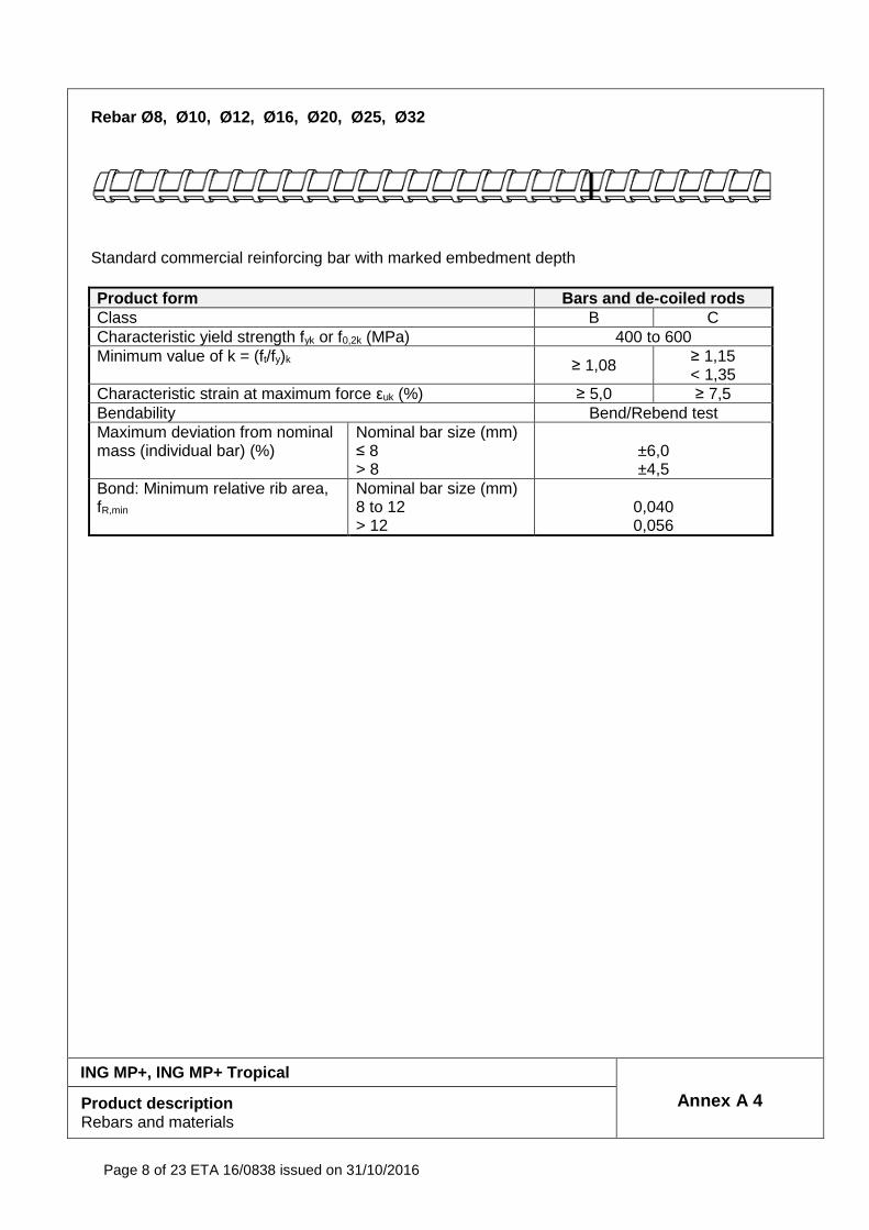
Rebar Ø8, Ø10, Ø12, Ø16, Ø20, Ø25, Ø32
Standard commercial reinforcing bar with marked embedment depth Product form Bars and de -coiled rods Class B C Characteristic yield strength fyk or f0,2k (MPa) 400 to 600 Minimum value of k = (ft/fy)k
≥ 1,08 ≥ 1,15 < 1,35
Characteristic strain at maximum force εuk (%) ≥ 5,0 ≥ 7,5 Bendability Bend/Rebend test Maximum deviation from nominal mass (individual bar) (%)
Nominal bar size (mm) ≤ 8 > 8
±6,0 ±4,5
Bond: Minimum relative rib area, fR,min
Nominal bar size (mm) 8 to 12 > 12
0,040 0,056
ING MP+, ING MP+ Tropical
Annex A 4 Product description Rebars and materials
Page 9 of 23 ETA 16/0838 issued on 31/10/2016
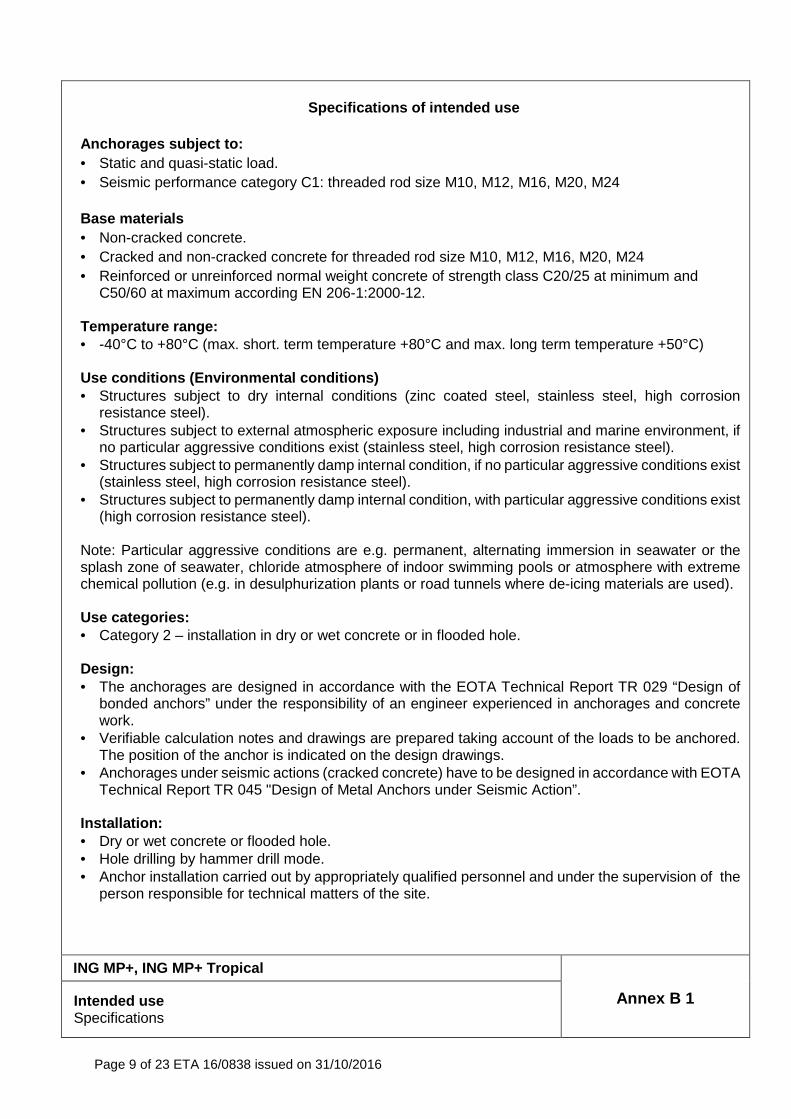
Specifications of intended use
Anchorages subject to: • Static and quasi-static load. • Seismic performance category C1: threaded rod size M10, M12, M16, M20, M24 Base materials • Non-cracked concrete. • Cracked and non-cracked concrete for threaded rod size M10, M12, M16, M20, M24 • Reinforced or unreinforced normal weight concrete of strength class C20/25 at minimum and
C50/60 at maximum according EN 206-1:2000-12. Temperature range: • -40°C to +80°C (max. short. term temperature +80°C and max. long term temperature +50°C) Use conditions (Environmental conditions) • Structures subject to dry internal conditions (zinc coated steel, stainless steel, high corrosion
resistance steel). • Structures subject to external atmospheric exposure including industrial and marine environment, if
no particular aggressive conditions exist (stainless steel, high corrosion resistance steel). • Structures subject to permanently damp internal condition, if no particular aggressive conditions exist
(stainless steel, high corrosion resistance steel). • Structures subject to permanently damp internal condition, with particular aggressive conditions exist
(high corrosion resistance steel). Note: Particular aggressive conditions are e.g. permanent, alternating immersion in seawater or the splash zone of seawater, chloride atmosphere of indoor swimming pools or atmosphere with extreme chemical pollution (e.g. in desulphurization plants or road tunnels where de-icing materials are used).
Use categories: • Category 2 – installation in dry or wet concrete or in flooded hole. Design: • The anchorages are designed in accordance with the EOTA Technical Report TR 029 “Design of
bonded anchors” under the responsibility of an engineer experienced in anchorages and concrete work.
• Verifiable calculation notes and drawings are prepared taking account of the loads to be anchored. The position of the anchor is indicated on the design drawings.
• Anchorages under seismic actions (cracked concrete) have to be designed in accordance with EOTA Technical Report TR 045 "Design of Metal Anchors under Seismic Action”.
Installation: • Dry or wet concrete or flooded hole. • Hole drilling by hammer drill mode. • Anchor installation carried out by appropriately qualified personnel and under the supervision of the
person responsible for technical matters of the site.
ING MP+, ING MP+ Tropical
Annex B 1 Intended use Specifications
Page 10 of 23 ETA 16/0838 issued on 31/10/2016
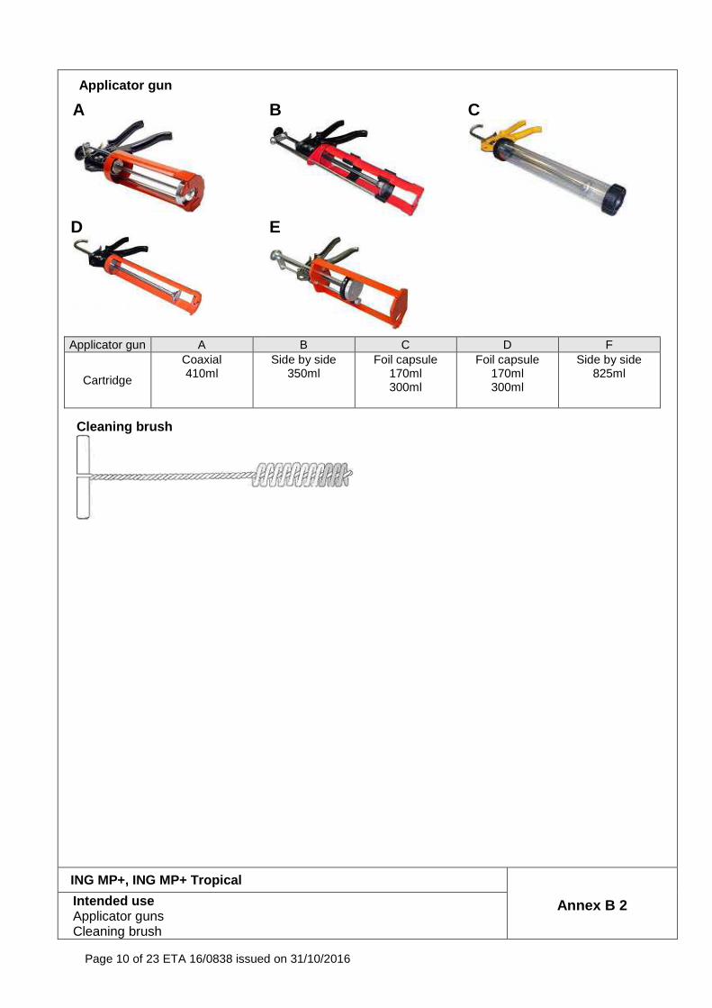
Applicator gun
A
B
C
D
E
Applicator gun A B C D F
Cartridge
Coaxial 410ml
Side by side 350ml
Foil capsule 170ml 300ml
Foil capsule 170ml 300ml
Side by side 825ml
Cleaning brush
ING MP+, ING MP+ Tropical
Annex B 2 Intended use Applicator guns Cleaning brush
Page 11 of 23 ETA 16/0838 issued on 31/10/2016
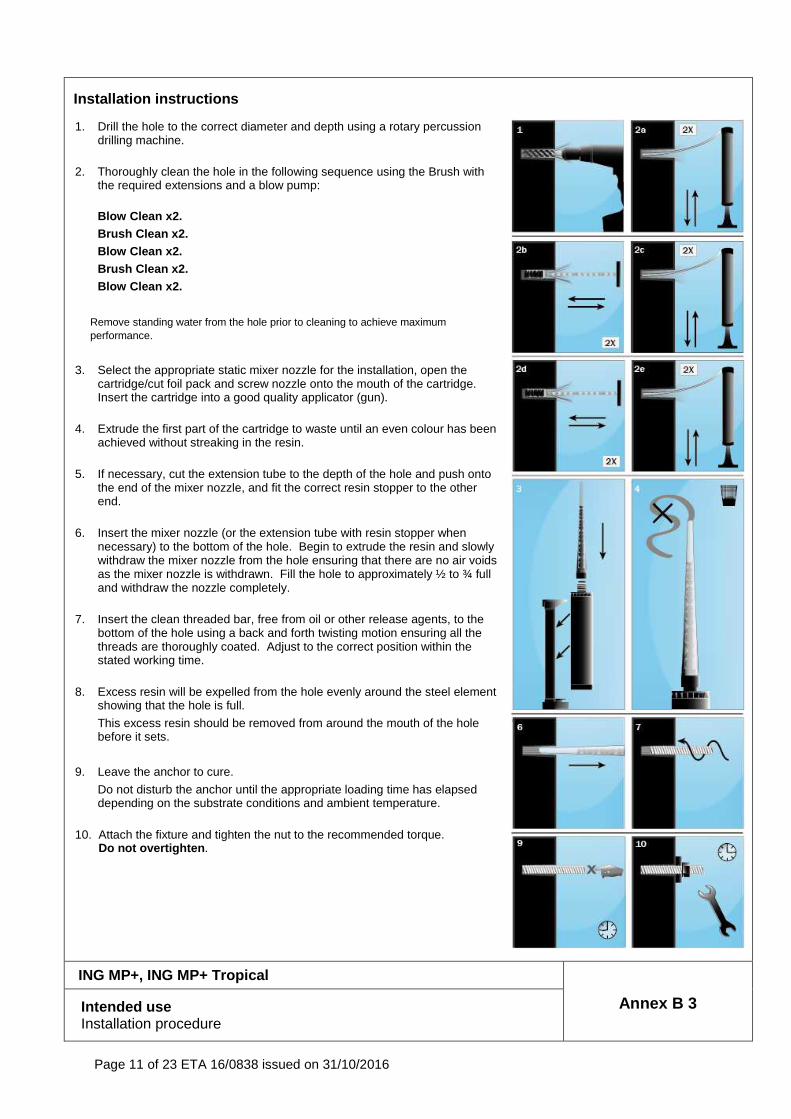
Installation instructions 1. Drill the hole to the correct diameter and depth using a rotary percussion
drilling machine.
2. Thoroughly clean the hole in the following sequence using the Brush with
the required extensions and a blow pump:
Blow Clean x2. Brush Clean x2. Blow Clean x2. Brush Clean x2. Blow Clean x2.
Remove standing water from the hole prior to cleaning to achieve maximum performance.
3. Select the appropriate static mixer nozzle for the installation, open the cartridge/cut foil pack and screw nozzle onto the mouth of the cartridge. Insert the cartridge into a good quality applicator (gun).
4. Extrude the first part of the cartridge to waste until an even colour has been
achieved without streaking in the resin.
5. If necessary, cut the extension tube to the depth of the hole and push onto
the end of the mixer nozzle, and fit the correct resin stopper to the other end.
6. Insert the mixer nozzle (or the extension tube with resin stopper when
necessary) to the bottom of the hole. Begin to extrude the resin and slowly withdraw the mixer nozzle from the hole ensuring that there are no air voids as the mixer nozzle is withdrawn. Fill the hole to approximately ½ to ¾ full and withdraw the nozzle completely.
7. Insert the clean threaded bar, free from oil or other release agents, to the
bottom of the hole using a back and forth twisting motion ensuring all the threads are thoroughly coated. Adjust to the correct position within the stated working time.
8. Excess resin will be expelled from the hole evenly around the steel element
showing that the hole is full.
This excess resin should be removed from around the mouth of the hole before it sets.
9. Leave the anchor to cure.
Do not disturb the anchor until the appropriate loading time has elapsed depending on the substrate conditions and ambient temperature.
10. Attach the fixture and tighten the nut to the recommended torque. Do not overtighten .
ING MP+, ING MP+ Tropical
Annex B 3 Intended use Installation procedure
Page 12 of 23 ETA 16/0838 issued on 31/10/2016
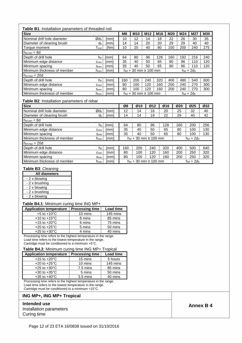
Table B1: Installation parameters of threaded rod Size M8 M10 M12 M16 M20 M24 M27 M30 Nominal drill hole diameter Ød0 [mm] 10 12 14 18 22 26 30 35 Diameter of cleaning brush db [mm] 14 14 20 20 29 29 40 40 Torque moment Tinst [Nm] 10 20 40 80 150 200 240 275 hef,min = 8d Depth of drill hole h0 [mm] 64 80 96 128 160 192 216 240 Minimum edge distance cmin [mm] 35 40 50 65 80 96 110 120 Minimum spacing smin [mm] 35 40 50 65 80 96 110 120 Minimum thickness of member hmin [mm] hef + 30 mm ≥ 100 mm hef + 2d0
hef,max = 20d Depth of drill hole h0 [mm] 160 200 240 320 400 480 540 600 Minimum edge distance cmin [mm] 80 100 120 160 200 240 270 300 Minimum spacing smin [mm] 80 100 120 160 200 240 270 300 Minimum thickness of member hmin [mm] hef + 30 mm ≥ 100 mm hef + 2d0
Table B2: Installation parameters of rebar Size Ø8 Ø10 Ø12 Ø16 Ø20 Ø25 Ø32 Nominal drill hole diameter Ød0 [mm] 12 14 16 20 25 32 40 Diameter of cleaning brush db [mm] 14 14 19 22 29 40 42 hef,min = 8d Depth of drill hole h0 [mm] 64 80 96 128 160 200 256 Minimum edge distance cmin [mm] 35 40 50 65 80 100 130 Minimum spacing smin [mm] 35 40 50 65 80 100 130 Minimum thickness of member hmin [mm] hef + 30 mm ≥ 100 mm hef + 2d0
hef,max = 20d Depth of drill hole h0 [mm] 160 200 240 320 400 500 640 Minimum edge distance cmin [mm] 80 100 120 160 200 250 320 Minimum spacing smin [mm] 80 100 120 160 200 250 320 Minimum thickness of member hmin [mm] hef + 30 mm ≥ 100 mm hef + 2d0
Table B3 : Cleaning All diameters
- 2 x blowing - 2 x brushing - 2 x blowing - 2 x brushing - 2 x blowing
Table B4.1 : Minimum curing time ING MP+ Application temperature Processing time Load time
+5 to +10°C 10 mins 145 mins +10 to +15°C 8 mins 85 mins +15 to +20°C 6 mins 75 mins +20 to +25°C 5 mins 50 mins +25 to +30°C 4 mins 40 mins
Processing time refers to the highest temperature in the range. Load time refers to the lowest temperature in the range. Cartridge must be conditioned to a minimum +5°C.
Table B4.2 : Minimum curing time ING MP+ Tropical Application temperature Processing time Load time
+15 to +20°C 15 mins 5 hours +20 to +25°C 10 mins 145 mins +25 to +30°C 7.5 mins 85 mins +30 to +35°C 5 mins 50 mins +35 to +40°C 3.5 mins 40 mins
Processing time refers to the highest temperature in the range. Load time refers to the lowest temperature in the range. Cartridge must be conditioned to a minimum +15°C.
ING MP+, ING MP+ Tropical
Annex B 4 Intended use Installation parameters Curing time
Page 13 of 23 ETA 16/0838 issued on 31/10/2016
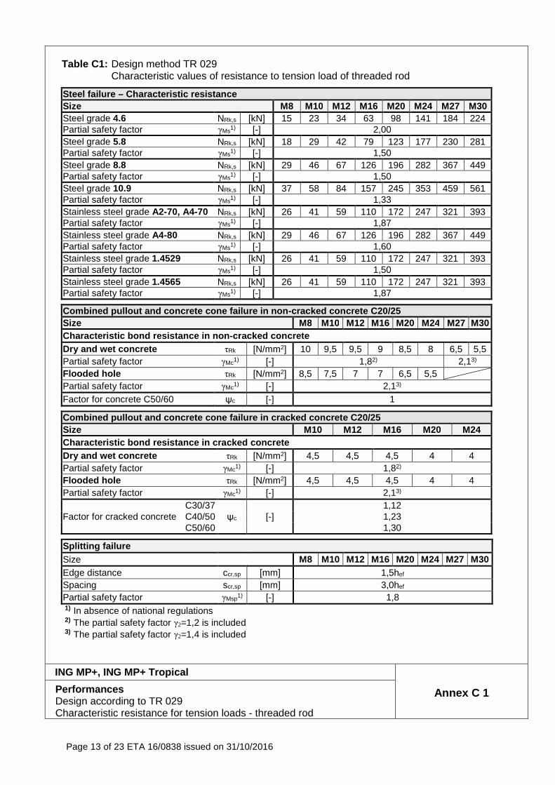
Table C1: Design method TR 029
Characteristic values of resistance to tension load of threaded rod
Steel failure – Characteristic resistance Size M8 M10 M12 M16 M20 M24 M27 M30 Steel grade 4.6 NRk,s [kN] 15 23 34 63 98 141 184 224 Partial safety factor γMs1) [-] 2,00 Steel grade 5.8 NRk,s [kN] 18 29 42 79 123 177 230 281 Partial safety factor γMs1) [-] 1,50 Steel grade 8.8 NRk,s [kN] 29 46 67 126 196 282 367 449 Partial safety factor γMs1) [-] 1,50 Steel grade 10.9 NRk,s [kN] 37 58 84 157 245 353 459 561 Partial safety factor γMs1) [-] 1,33 Stainless steel grade A2-70, A4-70 NRk,s [kN] 26 41 59 110 172 247 321 393 Partial safety factor γMs1) [-] 1,87 Stainless steel grade A4-80 NRk,s [kN] 29 46 67 126 196 282 367 449 Partial safety factor γMs1) [-] 1,60 Stainless steel grade 1.4529 NRk,s [kN] 26 41 59 110 172 247 321 393 Partial safety factor γMs1) [-] 1,50 Stainless steel grade 1.4565 NRk,s [kN] 26 41 59 110 172 247 321 393 Partial safety factor γMs1) [-] 1,87
Combined pullout and concrete cone failure in non -cracked concrete C20/25 Size M8 M10 M12 M16 M20 M24 M27 M30 Characteristic bond resistance in non-cracked concr ete Dry and wet concrete τRk [N/mm2] 10 9,5 9,5 9 8,5 8 6,5 5,5 Partial safety factor γMc1) [-] 1,82) 2,13) Flooded hole τRk [N/mm2] 8,5 7,5 7 7 6,5 5,5 Partial safety factor γMc1) [-] 2,13) Factor for concrete C50/60 ψc [-] 1
Combined pullout and concrete cone failure in cracked concrete C20/25 Size M10 M12 M16 M20 M24 Characteristic bond resistance in cracked concrete Dry and wet concrete τRk [N/mm2] 4,5 4,5 4,5 4 4 Partial safety factor γMc1) [-] 1,82) Flooded hole τRk [N/mm2] 4,5 4,5 4,5 4 4 Partial safety factor γMc1) [-] 2,13)
Factor for cracked concrete C30/37
ψc [-] 1,12
C40/50 1,23 C50/60 1,30
Splitting failure Size M8 M10 M12 M16 M20 M24 M27 M30 Edge distance ccr,sp [mm] 1,5hef
Spacing scr,sp [mm] 3,0hef
Partial safety factor γMsp1) [-] 1,8 1) In absence of national regulations 2) The partial safety factor γ2=1,2 is included 3) The partial safety factor γ2=1,4 is included
ING MP+, ING MP+ Tropical
Annex C 1 Performances Design according to TR 029 Characteristic resistance for tension loads - threaded rod
Page 14 of 23 ETA 16/0838 issued on 31/10/2016
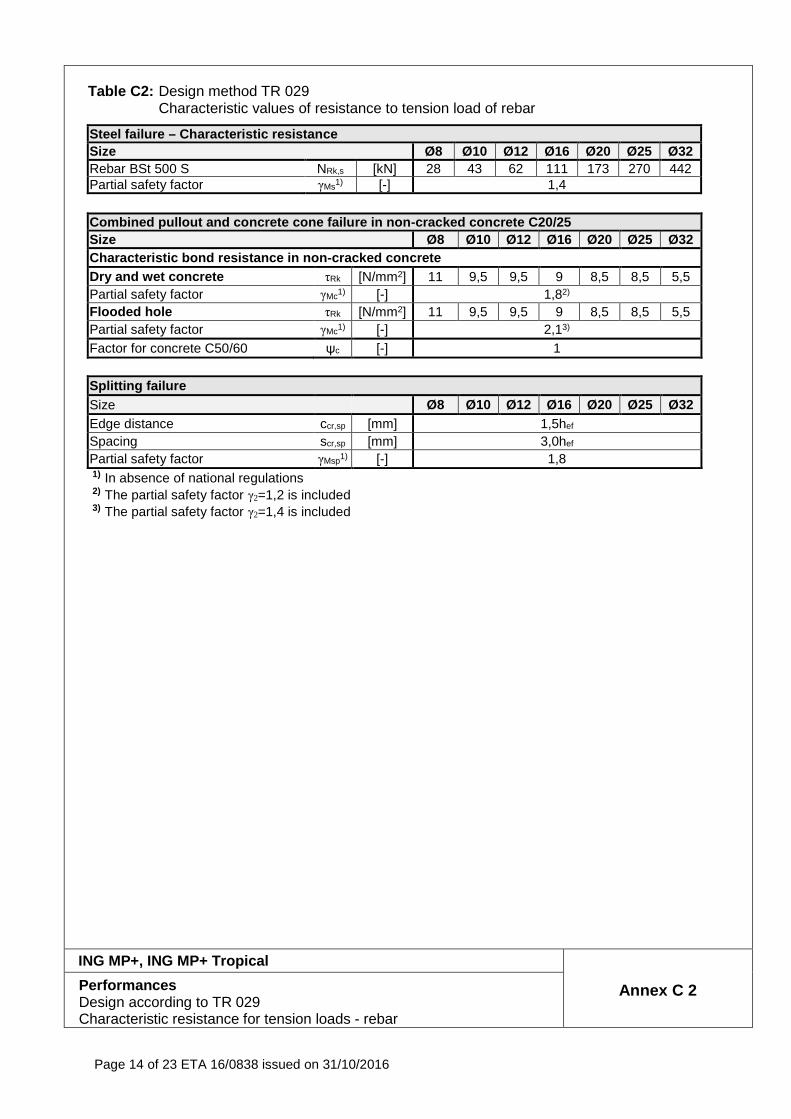
Table C2: Design method TR 029
Characteristic values of resistance to tension load of rebar
Steel failure – Characteristic resistance Size Ø8 Ø10 Ø12 Ø16 Ø20 Ø25 Ø32 Rebar BSt 500 S NRk,s [kN] 28 43 62 111 173 270 442 Partial safety factor γMs1) [-] 1,4
Combined pullout and concrete cone failure in non -cracked concrete C20/25 Size Ø8 Ø10 Ø12 Ø16 Ø20 Ø25 Ø32 Characteristic bond resistance in non-cracked concr ete Dry and wet concrete τRk [N/mm2] 11 9,5 9,5 9 8,5 8,5 5,5 Partial safety factor γMc1) [-] 1,82)
Flooded hole τRk [N/mm2] 11 9,5 9,5 9 8,5 8,5 5,5 Partial safety factor γMc1) [-] 2,13)
Factor for concrete C50/60 ψc [-] 1
Splitting failure Size Ø8 Ø10 Ø12 Ø16 Ø20 Ø25 Ø32 Edge distance ccr,sp [mm] 1,5hef
Spacing scr,sp [mm] 3,0hef
Partial safety factor γMsp1) [-] 1,8 1) In absence of national regulations 2) The partial safety factor γ2=1,2 is included 3) The partial safety factor γ2=1,4 is included
ING MP+, ING MP+ Tropical
Annex C 2 Performances Design according to TR 029 Characteristic resistance for tension loads - rebar
Page 15 of 23 ETA 16/0838 issued on 31/10/2016
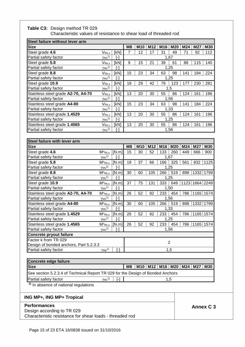
Table C3: Design method TR 029 Characteristic values of resistance to shear load of threaded rod
Steel failure without lever arm Size M8 M10 M12 M16 M20 M24 M27 M30 Steel grade 4.6 VRk,s [kN] 7 12 17 31 49 71 92 112 Partial safety factor γMs1) [-] 1,67 Steel grade 5.8 VRk,s [kN] 9 15 21 39 61 88 115 140 Partial safety factor γMs1) [-] 1,25 Steel grade 8.8 VRk,s [kN] 15 23 34 63 98 141 184 224 Partial safety factor γMs1) [-] 1,25 Steel grade 10.9 VRk,s [kN] 18 29 42 79 123 177 230 281 Partial safety factor γMs1) [-] 1,5 Stainless steel grade A2-70, A4-70 VRk,s [kN] 13 20 30 55 86 124 161 196 Partial safety factor γMs1) [-] 1,56 Stainless steel grade A4-80 VRk,s [kN] 15 23 34 63 98 141 184 224 Partial safety factor γMs1) [-] 1,33 Stainless steel grade 1.4529 VRk,s [kN] 13 20 30 55 86 124 161 196 Partial safety factor γMs1) [-] 1,25 Stainless steel grade 1.4565 VRk,s [kN] 13 20 30 55 86 124 161 196 Partial safety factor γMs1) [-] 1,56
Steel failure with lever arm Size M8 M10 M12 M16 M20 M24 M27 M30 Steel grade 4.6 MoRk,s [N.m] 15 30 52 133 260 449 666 900 Partial safety factor γMs1) [-] 1,67 Steel grade 5.8 MoRk,s [N.m] 19 37 66 166 325 561 832 1125 Partial safety factor γMs1) [-] 1,25 Steel grade 8.8 MoRk,s [N.m] 30 60 105 266 519 898 1332 1799 Partial safety factor γMs1) [-] 1,25 Steel grade 10.9 MoRk,s [N.m] 37 75 131 333 649 1123 1664 2249 Partial safety factor γMs1) [-] 1,50 Stainless steel grade A2-70, A4-70 MoRk,s [N.m] 26 52 92 233 454 786 1165 1574 Partial safety factor γMs1) [-] 1,56 Stainless steel grade A4-80 MoRk,s [N.m] 30 60 105 266 519 898 1332 1799 Partial safety factor γMs1) [-] 1,33 Stainless steel grade 1.4529 MoRk,s [N.m] 26 52 92 233 454 786 1165 1574 Partial safety factor γMs1) [-] 1,25 Stainless steel grade 1.4565 MoRk,s [N.m] 26 52 92 233 454 786 1165 1574 Partial safety factor γMs1) [-] 1,56 Concrete pryout failure Factor k from TR 029 Design of bonded anchors, Part 5.2.3.3
2
Partial safety factor γMp1) [-] 1,5
Concrete edge failure Size M8 M10 M12 M16 M20 M24 M27 M30
See section 5.2.3.4 of Technical Report TR 029 for the Design of Bonded Anchors
Partial safety factor γMc1) [-] 1,5 1) In absence of national regulations
ING MP+, ING MP+ Tropical
Annex C 3 Performances Design according to TR 029 Characteristic resistance for shear loads - threaded rod
Page 16 of 23 ETA 16/0838 issued on 31/10/2016
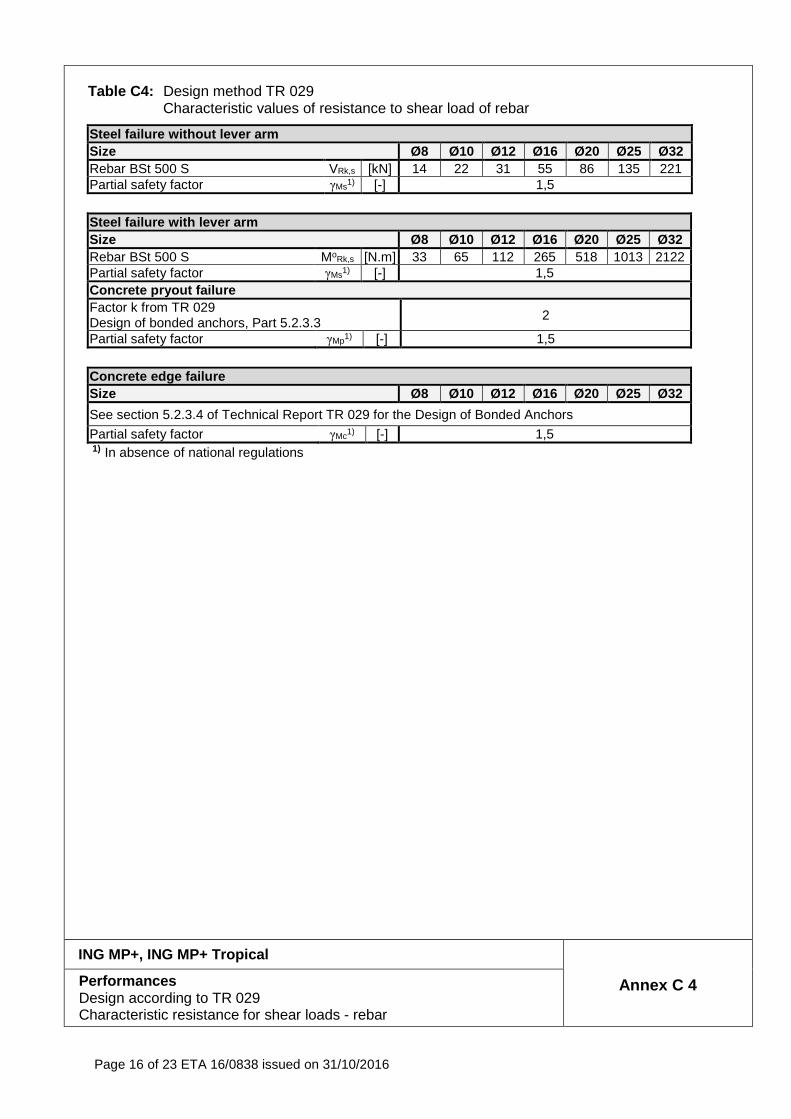
Table C4: Design method TR 029 Characteristic values of resistance to shear load of rebar
Steel failure without lever arm Size Ø8 Ø10 Ø12 Ø16 Ø20 Ø25 Ø32 Rebar BSt 500 S VRk,s [kN] 14 22 31 55 86 135 221 Partial safety factor γMs1) [-] 1,5
Steel failure with lever arm Size Ø8 Ø10 Ø12 Ø16 Ø20 Ø25 Ø32 Rebar BSt 500 S MoRk,s [N.m] 33 65 112 265 518 1013 2122 Partial safety factor γMs1) [-] 1,5 Concrete pryout failure Factor k from TR 029 Design of bonded anchors, Part 5.2.3.3
2
Partial safety factor γMp1) [-] 1,5
Concrete edge failure Size Ø8 Ø10 Ø12 Ø16 Ø20 Ø25 Ø32
See section 5.2.3.4 of Technical Report TR 029 for the Design of Bonded Anchors
Partial safety factor γMc1) [-] 1,5 1) In absence of national regulations
ING MP+, ING MP+ Tropical
Annex C 4 Performances Design according to TR 029 Characteristic resistance for shear loads - rebar
Page 17 of 23 ETA 16/0838 issued on 31/10/2016
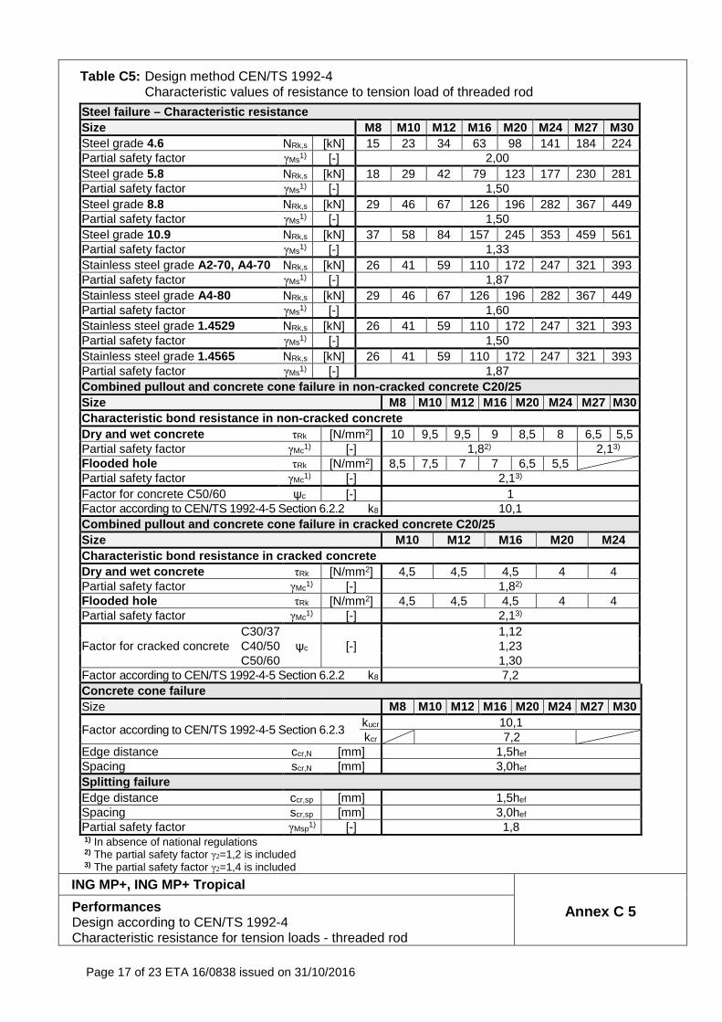
Table C5: Design method CEN/TS 1992-4 Characteristic values of resistance to tension load of threaded rod
Steel failure – Characteristic resistance Size M8 M10 M12 M16 M20 M24 M27 M30 Steel grade 4.6 NRk,s [kN] 15 23 34 63 98 141 184 224 Partial safety factor γMs1) [-] 2,00 Steel grade 5.8 NRk,s [kN] 18 29 42 79 123 177 230 281 Partial safety factor γMs1) [-] 1,50 Steel grade 8.8 NRk,s [kN] 29 46 67 126 196 282 367 449 Partial safety factor γMs1) [-] 1,50 Steel grade 10.9 NRk,s [kN] 37 58 84 157 245 353 459 561 Partial safety factor γMs1) [-] 1,33 Stainless steel grade A2-70, A4-70 NRk,s [kN] 26 41 59 110 172 247 321 393 Partial safety factor γMs1) [-] 1,87 Stainless steel grade A4-80 NRk,s [kN] 29 46 67 126 196 282 367 449 Partial safety factor γMs1) [-] 1,60 Stainless steel grade 1.4529 NRk,s [kN] 26 41 59 110 172 247 321 393 Partial safety factor γMs1) [-] 1,50 Stainless steel grade 1.4565 NRk,s [kN] 26 41 59 110 172 247 321 393 Partial safety factor γMs1) [-] 1,87 Combined pullout and concrete cone failure in non -cracked concrete C20/25 Size M8 M10 M12 M16 M20 M24 M27 M30 Characteristic bond resistance in non -cracked concrete Dry and wet concrete τRk [N/mm2] 10 9,5 9,5 9 8,5 8 6,5 5,5 Partial safety factor γMc1) [-] 1,82) 2,13) Flooded hole τRk [N/mm2] 8,5 7,5 7 7 6,5 5,5 Partial safety factor γMc1) [-] 2,13) Factor for concrete C50/60 ψc [-] 1 Factor according to CEN/TS 1992-4-5 Section 6.2.2 k8 10,1 Combined pullout and concrete cone failure in cracked concrete C20/25 Size M10 M12 M16 M20 M24 Charac teristic bond resistance in cracked concrete Dry and wet concrete τRk [N/mm2] 4,5 4,5 4,5 4 4 Partial safety factor γMc1) [-] 1,82) Flooded hole τRk [N/mm2] 4,5 4,5 4,5 4 4 Partial safety factor γMc1) [-] 2,13)
Factor for cracked concrete C30/37
ψc [-] 1,12
C40/50 1,23 C50/60 1,30
Factor according to CEN/TS 1992-4-5 Section 6.2.2 k8 7,2 Concrete cone failure Size M8 M10 M12 M16 M20 M24 M27 M30
Factor according to CEN/TS 1992-4-5 Section 6.2.3 kucr 10,1 kcr 7,2
Edge distance ccr,N [mm] 1,5hef
Spacing scr,N [mm] 3,0hef
Splitting failure Edge distance ccr,sp [mm] 1,5hef
Spacing scr,sp [mm] 3,0hef
Partial safety factor γMsp1) [-] 1,8 1) In absence of national regulations 2) The partial safety factor γ2=1,2 is included 3) The partial safety factor γ2=1,4 is included
ING MP+, ING MP+ Tropical
Annex C 5 Performances Design according to CEN/TS 1992-4 Characteristic resistance for tension loads - threaded rod
Page 18 of 23 ETA 16/0838 issued on 31/10/2016
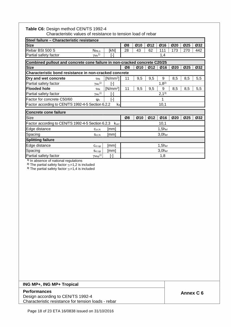
Table C6: Design method CEN/TS 1992-4 Characteristic values of resistance to tension load of rebar
Steel failure – Characteristic resistance Size Ø8 Ø10 Ø12 Ø16 Ø20 Ø25 Ø32 Rebar BSt 500 S NRk,s [kN] 28 43 62 111 173 270 442 Partial safety factor γMs1) [-] 1,4
Combined pullout and concrete cone failure in non -cracked concrete C20/25 Size Ø8 Ø10 Ø12 Ø16 Ø20 Ø25 Ø32 Characteristic bond resistance in non-cracked concr ete Dry and wet concrete τRk [N/mm2] 11 9,5 9,5 9 8,5 8,5 5,5 Partial safety factor γMc1) [-] 1,82)
Flooded hole τRk [N/mm2] 11 9,5 9,5 9 8,5 8,5 5,5 Partial safety factor γMc1) [-] 2,13)
Factor for concrete C50/60 ψc [-] 1 Factor according to CEN/TS 1992-4-5 Section 6.2.2 k8 10,1
Concrete cone failure Size Ø8 Ø10 Ø12 Ø16 Ø20 Ø25 Ø32 Factor according to CEN/TS 1992-4-5 Section 6.2.3 kucr 10,1 Edge distance ccr,N [mm] 1,5hef
Spacing scr,N [mm] 3,0hef
Splitting failure Edge distance ccr,sp [mm] 1,5hef
Spacing scr,sp [mm] 3,0hef
Partial safety factor γMsp1) [-] 1,8 1) In absence of national regulations 2) The partial safety factor γ2=1,2 is included 3) The partial safety factor γ2=1,4 is included
ING MP+, ING MP+ Tropical
Annex C 6 Performances Design according to CEN/TS 1992-4 Characteristic resistance for tension loads - rebar
Page 19 of 23 ETA 16/0838 issued on 31/10/2016
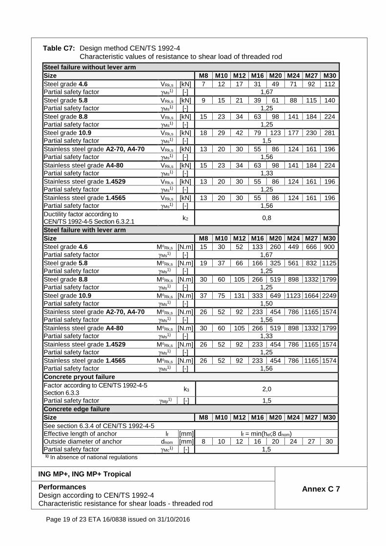
Table C7: Design method CEN/TS 1992-4 Characteristic values of resistance to shear load of threaded rod
Steel failure without lever arm Size M8 M10 M12 M16 M20 M24 M27 M30 Steel grade 4.6 VRk,s [kN] 7 12 17 31 49 71 92 112 Partial safety factor γMs1) [-] 1,67 Steel grade 5.8 VRk,s [kN] 9 15 21 39 61 88 115 140 Partial safety factor γMs1) [-] 1,25 Steel grade 8.8 VRk,s [kN] 15 23 34 63 98 141 184 224 Partial safety factor γMs1) [-] 1,25 Steel grade 10.9 VRk,s [kN] 18 29 42 79 123 177 230 281 Partial safety factor γMs1) [-] 1,5 Stainless steel grade A2-70, A4-70 VRk,s [kN] 13 20 30 55 86 124 161 196 Partial safety factor γMs1) [-] 1,56 Stainless steel grade A4-80 VRk,s [kN] 15 23 34 63 98 141 184 224 Partial safety factor γMs1) [-] 1,33 Stainless steel grade 1.4529 VRk,s [kN] 13 20 30 55 86 124 161 196 Partial safety factor γMs1) [-] 1,25 Stainless steel grade 1.4565 VRk,s [kN] 13 20 30 55 86 124 161 196 Partial safety factor γMs1) [-] 1,56 Ductility factor according to CEN/TS 1992-4-5 Section 6.3.2.1 k2 0,8
Steel failure with lever arm Size M8 M10 M12 M16 M20 M24 M27 M30 Steel grade 4.6 MoRk,s [N.m] 15 30 52 133 260 449 666 900 Partial safety factor γMs1) [-] 1,67 Steel grade 5.8 MoRk,s [N.m] 19 37 66 166 325 561 832 1125 Partial safety factor γMs1) [-] 1,25 Steel grade 8.8 MoRk,s [N.m] 30 60 105 266 519 898 1332 1799 Partial safety factor γMs1) [-] 1,25 Steel grade 10.9 MoRk,s [N.m] 37 75 131 333 649 1123 1664 2249 Partial safety factor γMs1) [-] 1,50 Stainless steel grade A2-70, A4-70 MoRk,s [N.m] 26 52 92 233 454 786 1165 1574 Partial safety factor γMs1) [-] 1,56 Stainless steel grade A4-80 MoRk,s [N.m] 30 60 105 266 519 898 1332 1799 Partial safety factor γMs1) [-] 1,33 Stainless steel grade 1.4529 MoRk,s [N.m] 26 52 92 233 454 786 1165 1574 Partial safety factor γMs1) [-] 1,25 Stainless steel grade 1.4565 MoRk,s [N.m] 26 52 92 233 454 786 1165 1574 Partial safety factor γMs1) [-] 1,56 Concrete pryout failure Factor according to CEN/TS 1992-4-5 Section 6.3.3
k3 2,0
Partial safety factor γMp1) [-] 1,5 Concrete edge failure Size M8 M10 M12 M16 M20 M24 M27 M30 See section 6.3.4 of CEN/TS 1992-4-5 Effective length of anchor lf [mm] lf = min(hef;8 dnom) Outside diameter of anchor dnom [mm] 8 10 12 16 20 24 27 30 Partial safety factor γMc1) [-] 1,5 1) In absence of national regulations
ING MP+, ING MP+ Tropical
Annex C 7 Performances Design according to CEN/TS 1992-4 Characteristic resistance for shear loads - threaded rod
Page 20 of 23 ETA 16/0838 issued on 31/10/2016
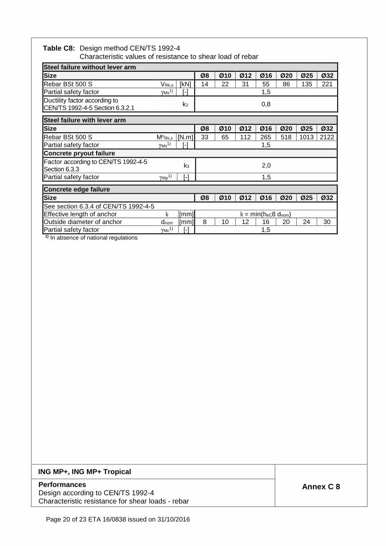
Table C8: Design method CEN/TS 1992-4 Characteristic values of resistance to shear load of rebar
Steel failure without lever arm Size Ø8 Ø10 Ø12 Ø16 Ø20 Ø25 Ø32 Rebar BSt 500 S VRk,s [kN] 14 22 31 55 86 135 221 Partial safety factor γMs1) [-] 1,5 Ductility factor according to CEN/TS 1992-4-5 Section 6.3.2.1 k2 0,8
Steel failure with lever arm Size Ø8 Ø10 Ø12 Ø16 Ø20 Ø25 Ø32 Rebar BSt 500 S MoRk,s [N.m] 33 65 112 265 518 1013 2122 Partial safety factor γMs1) [-] 1,5 Concrete pryout failure Factor according to CEN/TS 1992-4-5 Section 6.3.3
k3 2,0
Partial safety factor γMp1) [-] 1,5
Concrete edge failure Size Ø8 Ø10 Ø12 Ø16 Ø20 Ø25 Ø32 See section 6.3.4 of CEN/TS 1992-4-5 Effective length of anchor lf [mm] lf = min(hef;8 dnom) Outside diameter of anchor dnom [mm] 8 10 12 16 20 24 30 Partial safety factor γMc1) [-] 1,5 1) In absence of national regulations
ING MP+, ING MP+ Tropical
Annex C 8 Performances Design according to CEN/TS 1992-4 Characteristic resistance for shear loads - rebar
Page 21 of 23 ETA 16/0838 issued on 31/10/2016
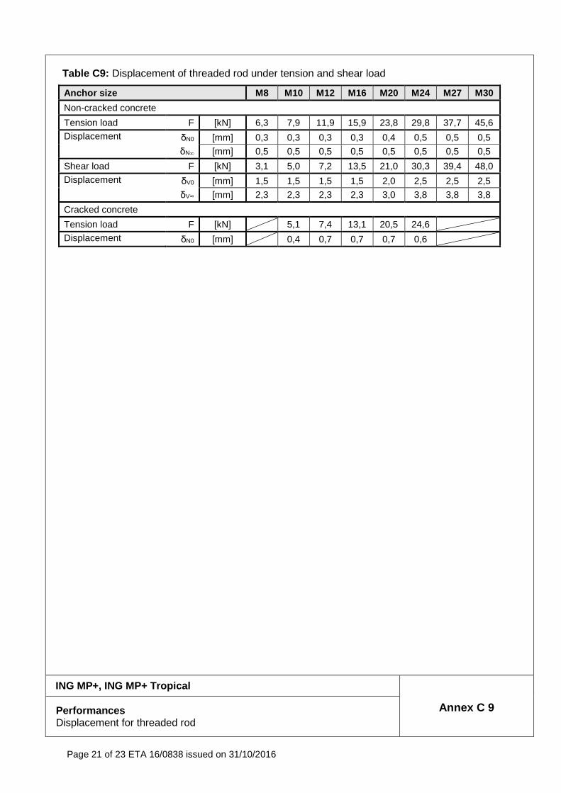
Table C9: Displacement of threaded rod under tension and shear load
Anchor size M8 M10 M12 M16 M20 M24 M27 M30
Non-cracked concrete
Tension load F [kN] 6,3 7,9 11,9 15,9 23,8 29,8 37,7 45,6 Displacement δN0 [mm] 0,3 0,3 0,3 0,3 0,4 0,5 0,5 0,5
δN∞ [mm] 0,5 0,5 0,5 0,5 0,5 0,5 0,5 0,5
Shear load F [kN] 3,1 5,0 7,2 13,5 21,0 30,3 39,4 48,0
Displacement δV0 [mm] 1,5 1,5 1,5 1,5 2,0 2,5 2,5 2,5
δV∞ [mm] 2,3 2,3 2,3 2,3 3,0 3,8 3,8 3,8
Cracked concrete
Tension load F [kN] 5,1 7,4 13,1 20,5 24,6
Displacement δN0 [mm] 0,4 0,7 0,7 0,7 0,6
ING MP+, ING MP+ Tropical
Annex C 9 Performances Displacement for threaded rod
Page 22 of 23 ETA 16/0838 issued on 31/10/2016
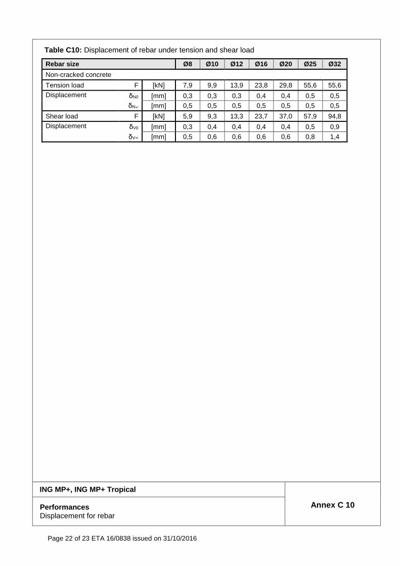
Table C10: Displacement of rebar under tension and shear load
Rebar size Ø8 Ø10 Ø12 Ø16 Ø20 Ø25 Ø32
Non-cracked concrete
Tension load F [kN] 7,9 9,9 13,9 23,8 29,8 55,6 55,6
Displacement δN0 [mm] 0,3 0,3 0,3 0,4 0,4 0,5 0,5
δN∞ [mm] 0,5 0,5 0,5 0,5 0,5 0,5 0,5
Shear load F [kN] 5,9 9,3 13,3 23,7 37,0 57,9 94,8
Displacement δV0 [mm] 0,3 0,4 0,4 0,4 0,4 0,5 0,9
δV∞ [mm] 0,5 0,6 0,6 0,6 0,6 0,8 1,4
ING MP+, ING MP+ Tropical
Annex C 10 Performances Displacement for rebar
Page 23 of 23 ETA 16/0838 issued on 31/10/2016
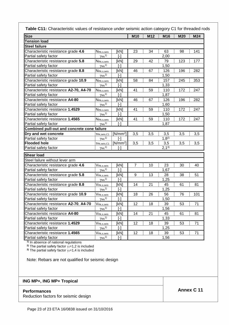
Table C11: Characteristic values of resistance under seismic action category C1 for threaded rods
Size M10 M12 M16 M20 M24 Tension load Steel failure Characteristic resistance grade 4.6 NRk,s,seis [kN] 23 34 63 98 141 Partial safety factor γMs1) [-] 2,00 Characteristic resistance grade 5.8 NRk,s,seis [kN] 29 42 79 123 177 Partial safety factor γMs1) [-] 1,50 Characteristic resistance grade 8.8 NRk,s,seis [kN] 46 67 126 196 282 Partial safety factor γMs1) [-] 1,50 Characteristic resistance grade 10.9 NRk,s,seis [kN] 58 84 157 245 353 Partial safety factor γMs1) [-] 1,33 Characteristic resistance A2-70, A4-70 NRk,s,seis [kN] 41 59 110 172 247 Partial safety factor γMs1) [-] 1,87 Characteristic resistance A4-80 NRk,s,seis [kN] 46 67 126 196 282 Partial safety factor γMs1) [-] 1,60 Characteristic resistance 1.4529 NRk,s,seis [kN] 41 59 110 172 247 Partial safety factor γMs1) [-] 1,50 Characteristic resistance 1.4565 NRk,s,seis [kN] 41 59 110 172 247 Partial safety factor γMs1) [-] 1,87 Combined pull -out and concrete cone failure Dry and wet concrete τRk,seis,C1 [N/mm2] 3,5 3,5 3,5 3,5 3,5 Partial safety factor γMc1) [-] 1,82) Flooded hole τRk,seis,C1 [N/mm2] 3,5 3,5 3,5 3,5 3,5 Partial safety factor γMc1) [-] 2,13)
Shear load Steel failure without lever arm Characteristic resistance grade 4.6 VRk,s,seis [kN] 7 10 23 30 40 Partial safety factor γMs1) [-] 1,67 Characteristic resistance grade 5.8 VRk,s,seis [kN] 9 13 28 38 51 Partial safety factor γMs1) [-] 1,25 Characteristic resistance grade 8.8 VRk,s,seis [kN] 14 21 45 61 81 Partial safety factor γMs1) [-] 1,25 Characteristic resistance grade 10.9 VRk,s,seis [kN] 18 26 56 76 101 Partial safety factor γMs1) [-] 1,50 Characteristic resistance A2-70, A4-70 VRk,s,seis [kN] 12 18 39 53 71 Partial safety factor γMs1) [-] 1,56 Characteristic resistance A4-80 VRk,s,seis [kN] 14 21 45 61 81 Partial safety factor γMs1) [-] 1,33 Characteristic resistance 1.4529 VRk,s,seis [kN] 12 18 39 53 71 Partial safety factor γMs1) [-] 1,25 Characteristic resistance 1.4565 VRk,s,seis [kN] 12 18 39 53 71 Partial safety factor γMs1) [-] 1,56
1) In absence of national regulations 2) The partial safety factor γ2=1,2 is included 3) The partial safety factor γ2=1,4 is included Note: Rebars are not qualified for seismic design
ING MP+, ING MP+ Tropical
Annex C 11 Performances Reduction factors for seismic design