Embed Size (px)
Citation preview
SCC 1500C
SANY CRAWLER CRANE SCC1500C
2 3
SCC1500CP3
P11
P20
SCC1500C Crawler CraneOutline DimensionsPerformance Data
Transportation DimensionsAssembly Diagram
SpecificationsUperworksUndercarriageOperation DeviceSafety Device
Combination of operating conditionsOperating Condition Combination
H Operating Condition FJ Operating Condition
04 Outline Dimensions05 Performance Data06 Transportation Dimensions10 Assembly Diagram
content
CRAWLER CRANE
SANY CRAWLER CRANE SCC1500C
4 5
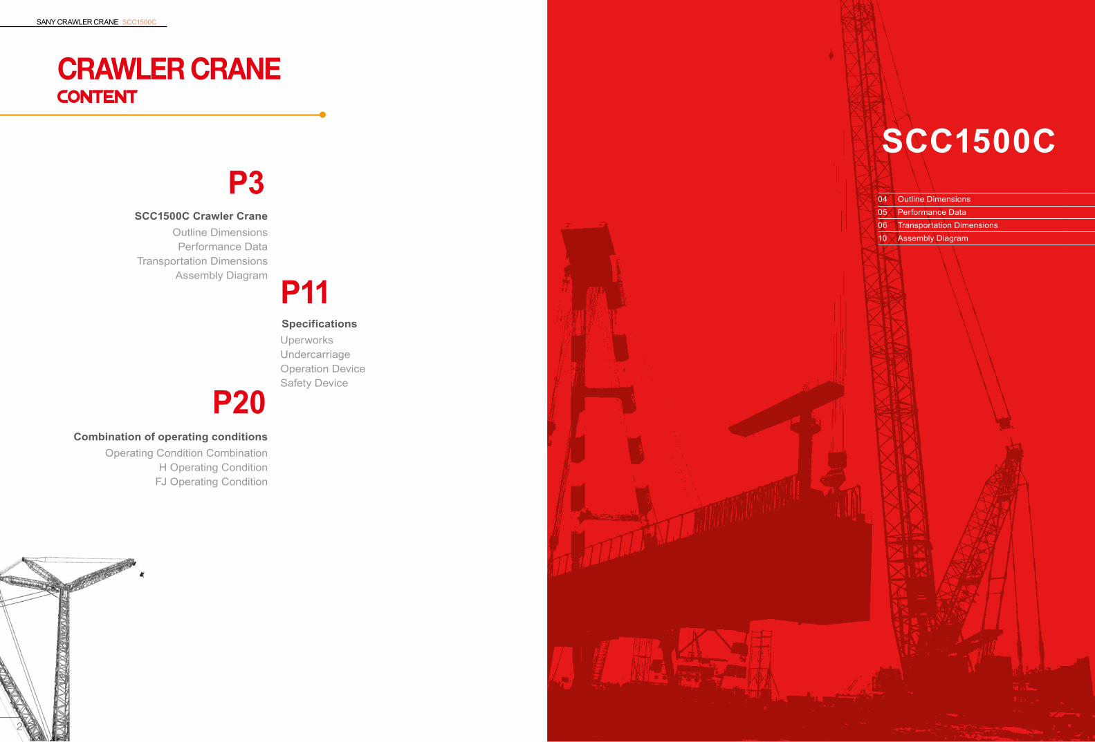
OUTLINE dimensions Performance Data
Main technical parameters of 1500C crawler crane
Performance index Unit Data
Boom operating condition
Maximum lifting capacity t 150
Boom length m 18~81
Boom luffing angle ° 30~ 80
Fixed jib operating condition
Max. length boom + Max. length jib m (69+31)/(75+13)
Angle between boom and fixed jib ° 15,30
Speed parameters
Rope speed of main and auxiliary winches m/min 0~125
Rope speed of Luffing winch(outermost) m/min (0~24)×2
Swing speed rpm 0~2
Traveling speed km/h 0~1.2/0~0.6(two speeds)
Gradeability % 30
Engine Output power/rated rotational speed kW/rpm 242 /2100
Transportation parameter
Maximum transport weight of single unit t 50.2
Transportation dimension (length*width*height) mm 10230×3470×3500
Other parameters Average ground pressure MPa 0.09345703460
1605
821571823555
18m
basic
boom
and 8
1m m
ax. b
oom
length
R6511
423732
93
3694
442 14
19
1284
1476 22
6437
0
339939
5888
02
5630
1100
6730
62897982
4603 1400
Basic Dimensions of the Whole Machine of SCC1500C crawler crane
SANY CRAWLER CRANE SCC1500C
6 7
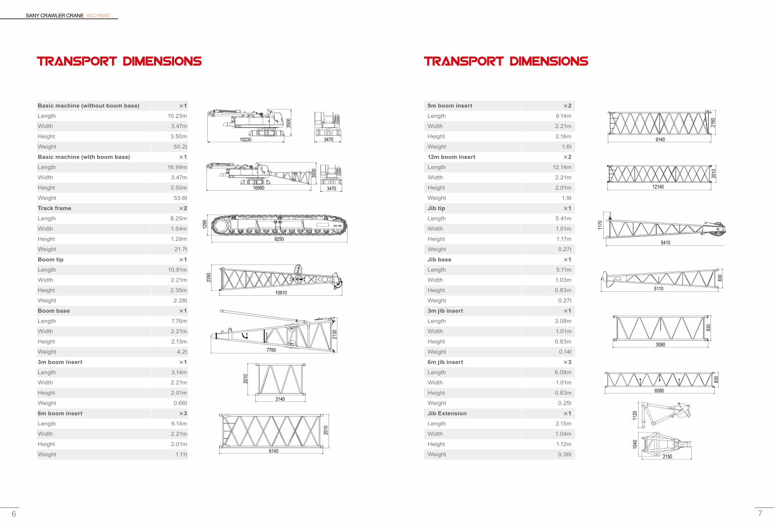
Transport Dimensions
Basic machine (without boom base) ×1
Length 10.23m
Width 3.47m
Height 3.50m
Weight 50.2t
Basic machine (with boom base) ×1
Length 16.99m
Width 3.47m
Height 3.50m
Weight 53.6t
Track frame ×2
Length 8.25m
Width 1.54m
Height 1.29m
Weight 21.7t
Boom tip ×1
Length 10.91m
Width 2.21m
Height 2.35m
Weight 2.28t
Boom base ×1
Length 7.76m
Width 2.21m
Height 2.13m
Weight 4.2t
3m boom insert ×1
Length 3.14m
Width 2.21m
Height 2.01m
Weight 0.66t
6m boom insert ×3
Length 6.14m
Width 2.21m
Height 2.01m
Weight 1.11t
Transport Dimensions
9m boom insert ×2
Length 9.14m
Width 2.21m
Height 2.16m
Weight 1.6t
12m boom insert ×2
Length 12.14m
Width 2.21m
Height 2.01m
Weight 1.9t
Jib tip ×1
Length 5.41m
Width 1.01m
Height 1.17m
Weight 0.27t
Jib base ×1
Length 5.11m
Width 1.03m
Height 0.83m
Weight 0.27t
3m jib insert ×1
Length 3.08m
Width 1.01m
Height 0.83m
Weight 0.14t
6m jib insert ×3
Length 6.08m
Width 1.01m
Height 0.83m
Weight 0.25t
Jib Extension ×1
Length 2.15m
Width 1.04m
Height 1.12m
Weight 0.36t6140
2010
3140
2010
7760
2130
10910
2350
10230 3470
3500
3500
16990 3470
8250
1290
1040
1120
2150
6080
830
3080
830
5110
830
5410
1170
12140
2010
9140
2160
SANY CRAWLER CRANE SCC1500C
8 9
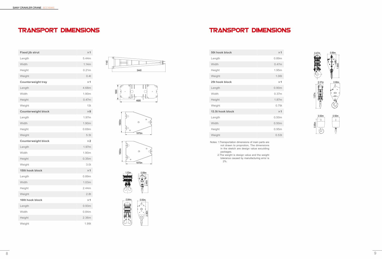
Transport Dimensions
Fixed jib strut ×1
Length 5.44m
Width 1.14m
Height 0.21m
Weight 0.4t
Counterweight tray ×1
Length 4.68m
Width 1.90m
Height 0.47m
Weight 13t
Counterweight block ×8
Length 1.97m
Width 1.90m
Height 0.69m
Weight 5.5t
Counterweight block ×2
Length 1.97m
Width 1.90m
Height 0.35m
Weight 3.0t
150t hook block ×1
Length 0.89m
Width 1.03m
Height 2.44m
Weight 2.8t
100t hook block ×1
Length 0.93m
Width 0.84m
Height 2.36m
Weight 1.99t
Transport Dimensions
50t hook block ×1
Length 0.89m
Width 0.47m
Height 1.95m
Weight 1.06t
25t hook block ×1
Length 0.90m
Width 0.37m
Height 1.87m
Weight 0.79t
13.5t hook block ×1
Length 0.50m
Width 0.50m
Height 0.95m
Weight 0.53t
0.84m 0.93m
2.36
m2.
44m
1900
m19
00m
1.03m 0.89m
1970m
1970m
1900
4680
5440
1140
0.37m 0.90m
1.87
m0.
95m
0.50m 0.50m
1.95
m
0.47m 0.89m
Notes: 1.Transportation dimensions of main parts are not drawn to proprotion, The dimensions in the sketch are design value exculding packages.
2.The weight is design value and the weight tolerance caused by manufacturing error is ±2%.
SANY CRAWLER CRANE SCC1500C
10 11
SCC1500C
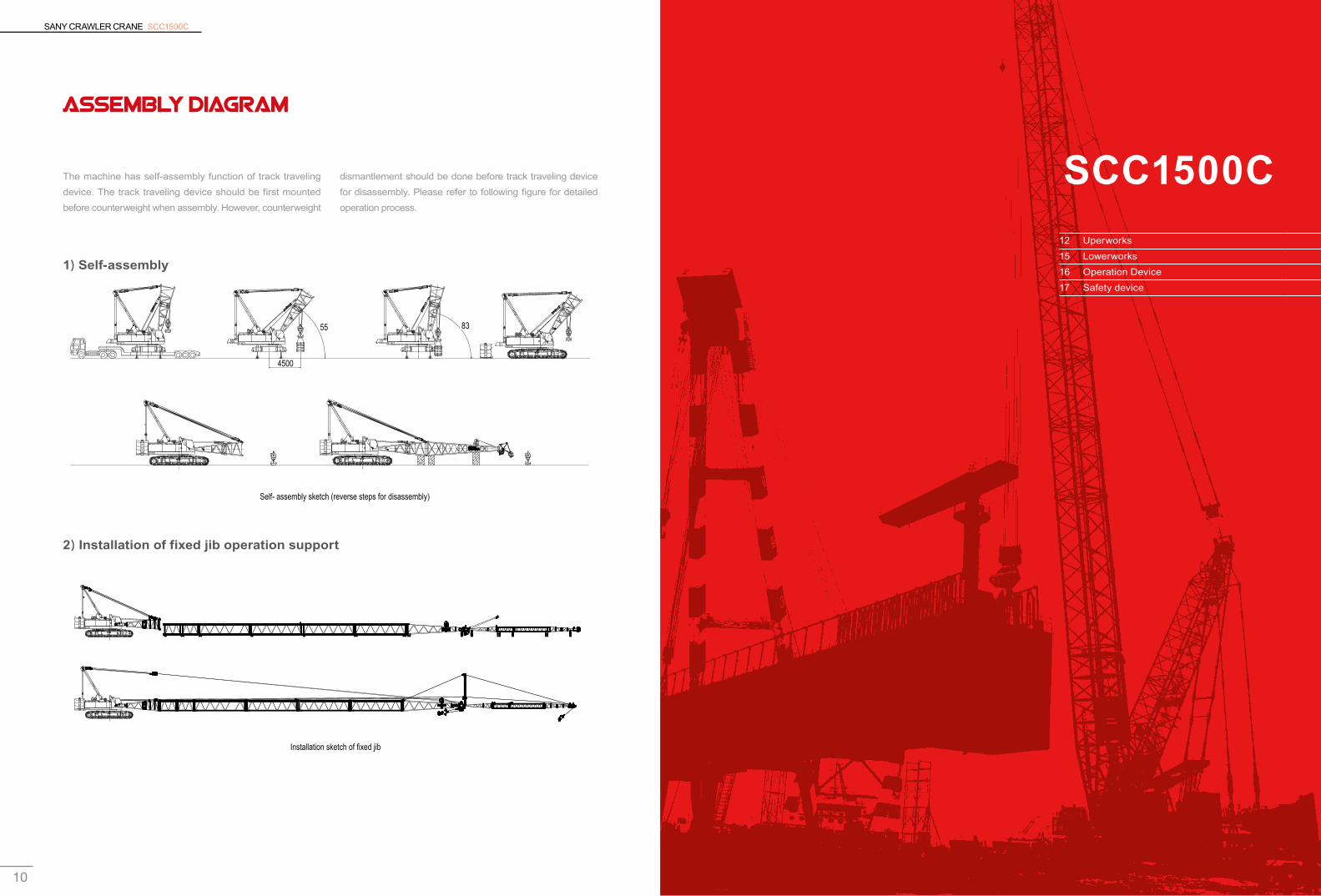
Installation sketch of fixed jib
Self- assembly sketch (reverse steps for disassembly)
4500
55° 83°
Assembly Diagram
The machine has self-assembly function of track traveling device. The track traveling device should be first mounted before counterweight when assembly. However, counterweight
1)Self-assembly
2)Installation of fixed jib operation support
dismantlement should be done before track traveling device for disassembly. Please refer to following figure for detailed operation process.
12 Uperworks15 Lowerworks16 Operation Device17 Safety device
SANY CRAWLER CRANE SCC1500C
12 13
Main lifting device
Drum diameter 496mmRated tension of single wire speed of the outermost layer 0~125m/min
Diameter of steel wire rope 26mm
Length of steel wire rope of main winch 350m
Rated single line pull 13.1t
Auxiliary lifting device
Drum diameter 496mmRated tension of single wire speed of the outermost layer 0~125m/min
Diameter of steel wire rope 26mm
Length of auxiliary winch steel wire rope 300m
Rated single line pull 13.1t
1)EngineImported Cummins QSL9, inline 6-cylinders. ■
Rated power / speed: 242KW/2100rpm. ■
Maximum torque: 1424N·m/1500rpm. ■
Emission standards:European tier 3. ■
Air filter: double filtration system composed of air pre- ■
filter and air filter.Fuel tank: capacity of 400L with oil leveler and ■
electronic display for fuel oil volume.Emission standard: Tier III. ■
2)Electrical control systemController, combination instrument, engine, load ■
moment indicator, remote control terminal apply CAN bus techniques for data communication. Combined instrument can display parameters such ■
as engine rotating speed, fuel quantity, machine oil pressure, servo pressure, wind speed, the engine operating working hours and primary winch lock, primary-to-amplitude winch lock, turn lock and other working conditions.Reliability: International or industrial famous brands ■
shall be used for main electric devices. They mainly include load moment limiter, controller, displayer, sensor, monitoring switch, control switch, electric wires and cables.Comfort: Electric parameters of various points can ■
be shown by instruments, including the operation parameters such as engine speed, fuel oil volume, machine oil pressure, servo pressure, wind speed and operation time etc. and the working state such as main winch locking, boom locking and slewing locking. Installation and operation modes can be separated to lock the main hydraulic action and to lighten drivers’ operation strength.Advancement: It adopts the overall CAN bus system, ■
load power limit control, redundancy communication check and optional global positioning and remote monitoring program.
5)Swing mechanismIt is driven by swing motor and buffered hydraulically ■
to provide 360° rotation.Brake: Normally closed, embedded, wet type, and ■
spring disc-type brake, with spring force braking and oil pressure releasing.Swing lock: swing lock device is employed for non- ■
impact on the slewing upper part during the load traveling and transportation process. Swing ring: 3-rows roller column type slewing ring. ■
Swing speed: 0-2.0r/min. ■
6)Luffing mechanismIt is fitted with double luffing winch drums, with ratchet wheel & pawl locking device for middle spacer plate of double drum so as to guarantee parking safety of suspension boom under non-operation status.
Luffing mechanism
Winch diameter 460mm
Rated tension of single wire speed of the outermost layer (0~24)×2 m/min
Diameter of steel wire rope 20mm
Length of steel wire rope of luffing winch 320m
Rated single line pull 9.73t
3)Hydraulic SystemConfiguration of hydraulic system: adopt the world-renowned brands of hydraulic systems, including the main pump, main valve, control handle and motor reducer. It is efficient, energy saving, stable and reliable. I t has excel lent micro - rotat ion and per formance improvement, load sensing; limit load regulation makes the operation more stable. Adop t c on t ro l l ed hyd rau l i c o i l c oo l i ng sys tem independently.
4)Main and auxiliary hoisting mechanismsMain or auxiliary winch has advantages such as ■
individual drive, compact structure, easy installation, low abrasion and maintenance-free embedded wet brake so as to guarantee winch safety.Variable hydraulic motor shall realize the maximum ■
winch speed by automatic displacement adjustment according to load.High-quality stainless steel wire rope shall be adopted ■
with features of high hoisting safety and service life.Bag type rope head shall be adopted for convenient ■
detachment & installation of steel wire rope. Pawl and ratchet locking device shall be fitted for safer hoisting.
Uperworks

SANY CRAWLER CRANE SCC1500C
14 15
1)Crawler traveling deviceThe track frame on both sides adopts separate walk-driven devices. Walking motor can achieve lineal walk and turn of the whole machine through motor reducer and driving wheel.
2)Traveling brakeBuilt-in, wet, spring-loaded normal-engaged disk brake applies braking through spring force and release braking through oil pressure.
3)Track shoesHigh-strength alloy steel track link with longer life.
4)ChassisHydraulic cylinder is to drive power pin for connection to crawler system to facilitate installation and detachment. High-strength welded frame structure.
5)Traveling speedLow-speed:0.6 km/h ■
High-speed:1.2 km/h ■
Name Quantity Weight of single part Total weight
Counterweight block 6 5.5 33
Counterweight block 2 3 6
Counterweight tray 1 13 13
Total nominal counterweight (kg) 52
Additional counterweight 2 5.5 11
Total weight of all counterweight (kg) 63
8)CabNewly designed sliding-door cab, large area windows; ■
with near and far beam headlamp, rear-view mirrors and more open vision.Installed with heating and cool air conditioning, MP3 ■
player; seats, control handle; control button layout designed according to ergonomic; thus operation is more comfortable.
7)Counterweight 9)Control operationAll actions of crawler traveling device are realized by ■
traveling pedal (or control lever). The left track can be driven by the left traveling pedal (control lever) and right track by the right traveling pedal (control lever); the engine rotational speed can be controlled by the foot or hand throttle. Startup switch of engine is located on the right armrest box. Luffing or main winch control lever is located on the right armrest box and auxiliary winch and slewing control lever on the left box. Slewing locking button is located at the left side of left armrest box. The auxiliary operation box is at the left front of seat, with all switches on its control panel operated manually to realize corresponding functions.Traveling pedal (control lever) has automatic positive ■
function. That is, positive control direction is that of operator.
Lowerworks
SANY CRAWLER CRANE SCC1500C
16 17
1)Boom Truss structures; the main chord adopts high strength ■
structure steel; each section is connected with pins. Basic boom 18m: 7.5m tip +10.5m base. ■
Boom insert: 3m'× 1,6m× 3,9m× 2,12m× 2. ■
Boom Length: 18m~ 81m. ■
2)Fixed jibTruss structures; the main chord adopts high strength ■
structure steel; each section is connected with pins. Fixed jib can be mounted on the boom between 27m ■
and 75m.Basic boom: 5m tip +5m base. ■
Boom insert: 3m×1, 6m×3. ■
Jib Length: 13m~ 31m’. ■
The longest boom + jib: 69m boom +31m jib;75m boom ■
+ 13m jib.
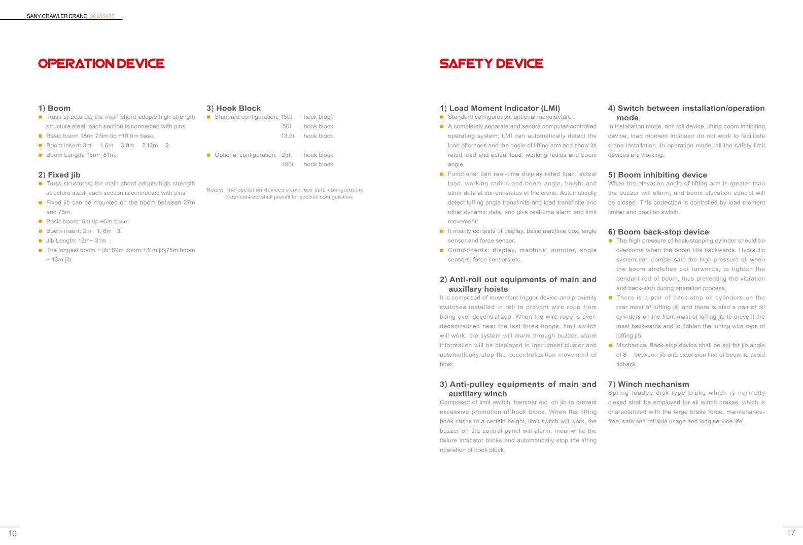
3)Hook BlockStandard configuration: 150t hook block ■
50t hook block13.5t hook block
Optional configuration: 25t hook block ■
100t hook block
Notes: The operation devices above are safe configuration; order contract shall prevail for specific configuration.
1)Load Moment Indicator (LMI)Standard configuration, optional manufacturer. ■
A completely separate and secure computer-controlled ■
operating system; LMI can automatically detect the load of cranes and the angle of lifting arm and show its rated load and actual load, working radius and boom angle.Functions: can real-time display rated load, actual ■
load, working radius and boom angle, height and other data at current status of the crane. Automatically detect luffing angle transfinite and load transfinite and other dynamic data, and give real-time alarm and limit movement. It mainly consists of display, basic machine box, angle ■
sensor and force sensor.Components: display, machine, monitor, angle ■
sensors, force sensors etc.
2)Anti-roll out equipments of main and auxillary hoists
It is composed of movement trigger device and proximity switches installed in roll to prevent wire rope from being over-decentralized. When the wire rope is over-decentralized near the last three hoops, limit switch will work, the system will alarm through buzzer, alarm information will be displayed in instrument cluster and automatically stop the decentralization movement of hoist.
3)Anti-pulley equipments of main and auxillary winch
Composed of limit switch, hammer etc. on jib to prevent excessive promotion of hook block. When the lifting hook raises to a certain height, limit switch will work, the buzzer on the control panel will alarm, meanwhile the failure indicator blinks and automatically stop the lifting operation of hook block.
4)Switch between installation/operation mode
In installation mode, anti roll device, lifting boom inhibiting device, load moment indicator do not work to facilitate crane installation. In operation mode, all the safety limit devices are working.
5)Boom inhibiting device When the elevation angle of lifting arm is greater than the buzzer will alarm, and boom elevation control will be closed. This protection is controlled by load moment limiter and position switch.
6)Boom back-stop deviceThe high pressure of back-stopping cylinder should be ■
overcome when the boom tilts backwards. Hydraulic system can compensate the high-pressure oil when the boom stretches out forwards, to tighten the pendant rod of boom, thus preventing the vibration and back-stop during operation process.There is a pair of back-stop oil cylinders on the ■
rear mast of luffing jib and there is also a pair of oil cylinders on the front mast of luffing jib to prevent the mast backwards and to tighten the luffing wire rope of luffing jib. Mechanical Back-stop device shall be set for jib angle ■
of 8° between jib and extension line of boom to avoid tipback.
7)Winch mechanismSpr ing- loaded disk-type brake which is normally closed shall be employed for all winch brakes, which is characterized with the large brake force, maintenance-free, safe and reliable usage and long service life.
Operation Device Safety device
SANY CRAWLER CRANE SCC1500C
18 19
8)Monitoring systemOperator in cab can monitor the real-time status of luffing drum, hoisting winch drum and vehicle tail by video camera with high resolution.
9)Self-diagnosis systemIt can generate fault and alarm information automatically to review the operation & electrification status of electrical lines so as to eliminate the electrical fault quickly.
10)Boom alarm lightIt is installed on the top of boom to overhead prompt,
without stopping the operation of boom at night.
11)Wind velocity indicator It is installed on the top of boom for the real-time monitoring of wind speed and then transfers the data to the cab for displaying them on the monitor.
12)Level gaugeElectronic leveling gauge can display tilt angle of upper works on monitor.
13)Boom angle sign platePendulum angle indicator device is located in boom base next to the cab for operator convenience.
14)Hook latchEach kind of lifting hook is fitted with baffle to avoid the steel wire falling-off.
15)Operation AlarmPress the horn to give an alarm before any operation of crane to prompt to other persons pay attention to safety.
16)Traveling or slewing promptOperation alrm lamp flickers and slewing buzzer rings during traveling or slewing traveling.
17)Permissible functional handleAll other function control handles will fail if the permissible functional handle can not be at the proper position, to avoid mis-operation caused by body collision when getting-on/off.
18)Seat-leaving Protection DeviceWhile the operator is not on the seat, all the control could not work.
19)Automatic reversing drivingNo matter the relative position between superstructure and undercarriage, the entire machine moves forwards if pushing the driving pedal forwards and backwards if pushing backwards.
20)Engine power limit load regulation and stall protection
Real-time monitoring shall be done for output power of engine. Power load can be adjusted to avoid engine suppression and stalling.
21)Monitoring DisplayHigh-resolution true color displayer and electric human-machine dialog displayer terminal can display operation parameters of engine system, operation status and parameters of hydraulic system, parameter status of various detection points and output points of electric system as well as real-time parameters under various ambient conditions.
SANY CRAWLER CRANE SCC1500C
20 21
SCC1500C
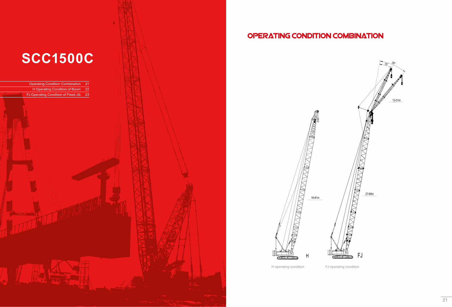
Operating Condition Combination
FJ operating conditionH operating condition
30°15°
13-31m
27-69m18-81m
Operating Condition Combination 21 H Operating Condition of Boom 22
FJ Operating Condition of Fixed Jib 23
SANY CRAWLER CRANE SCC1500C
22 23
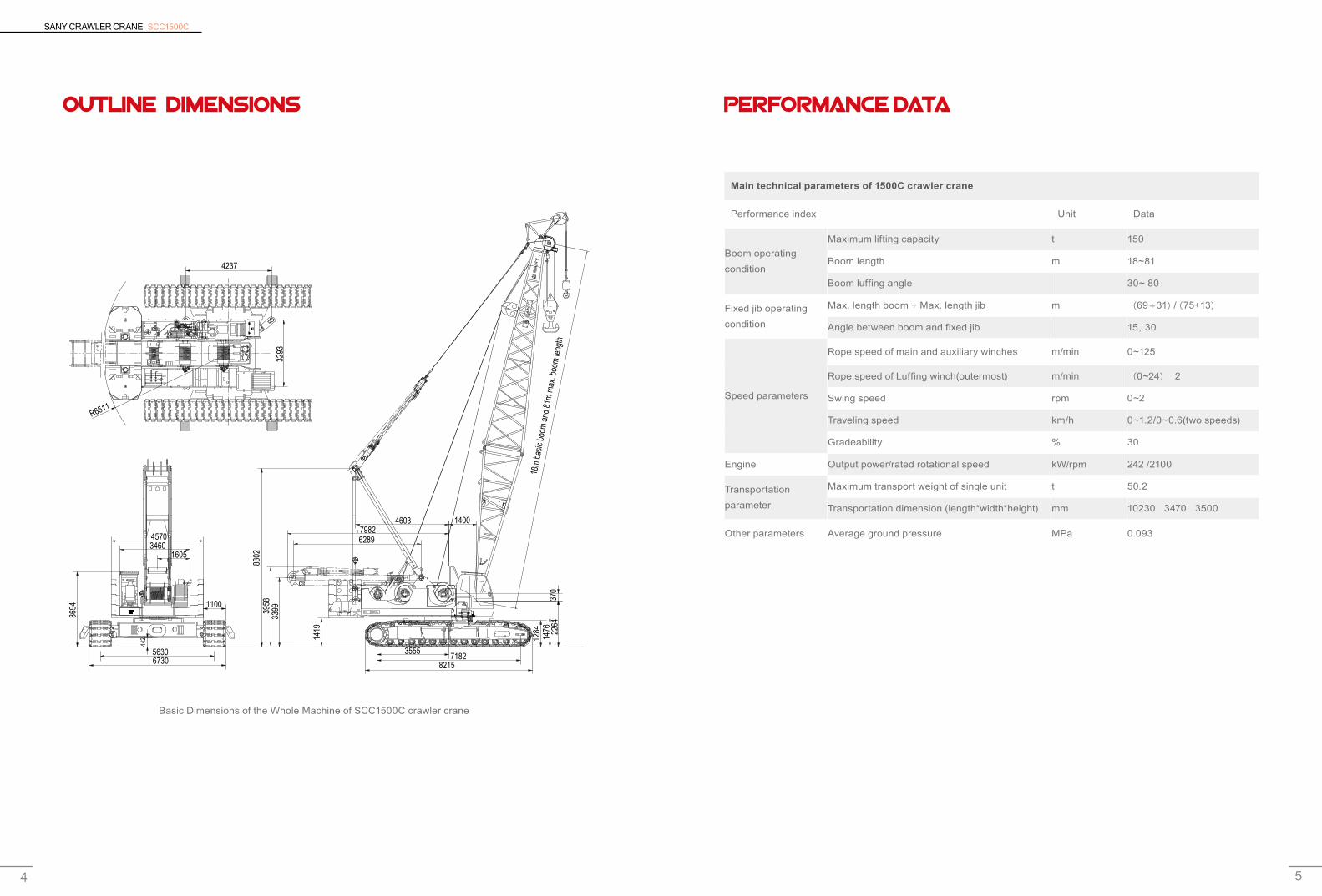
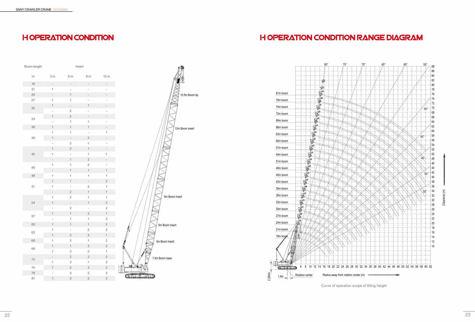
H OPERATION CONDITION
Boom length Insert
m 3 m 6 m 9 m 12 m
18 - - - -
21 1 - - -
24 - 1 - -
27 1 1 - -
301 - 1 -
- 2 - -
331 2 - -
- 1 1 -
36 1 1 1 -
39
1 1 - 1
1 - 2 -
- 2 1 -
42
1 2 1 -
1 - 1 1
- 1 2 -
451 1 2 -
- 1 1 1
48 1 1 1 1
51
1 1 - 2
1 - 2 1
- 2 1 1
54
1 2 1 1
1 - 1 2
- 2 - 2
571 1 2 1
- 1 1 2
60 1 1 1 2
631 - 2 2
1 2 2 1
66 1 2 1 2
691 1 2 2
1 3 2 1
72- 2 2 2
1 3 1 2
75 1 2 2 2
78 - 3 2 2
81 1 3 2 2
H OPERATION CONDITION RANGE DIAGRAM
88868482807876747270686664626058565452504846444240383634323028262422201816141210
6
1.4m
2.26
4m8 10 12 14 16 18 20 22 24 26 28 30 32 34 36 38 40 42 44 46 48 50 52 54 56 58 60 62
78m boom
81m boom
75m boom
72m boom
69m boom
66m boom
63m boom
60m boom
57m boom
54m boom
51m boom
48m boom
45m boom
42m boom
39m boom
36m boom
33m boom
30m boom
27m boom
24m boom
21m boom
18m boom
Clea
ranc
e (m
)
30°
Radius away from rotation center (m)Rotation center
40°
35°
45°
50°
55°60°65°70°75°80°
10.5m Boom tip
12m Boom insert
9m Boom insert
6m Boom insert
3m Boom insert
7.5m Boom base
Curve of operation scope of lifting height
SANY CRAWLER CRANE SCC1500C
24 25
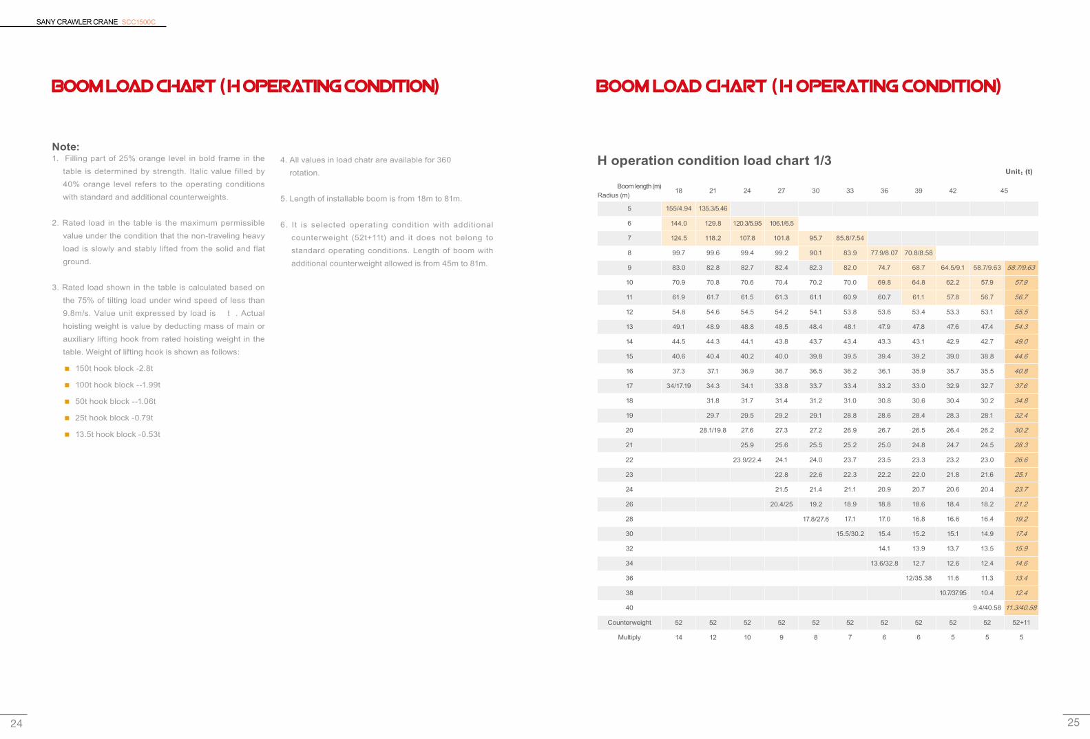
Boom load chart ( H operating condition)
Note:1. Filling part of 25% orange level in bold frame in the
table is determined by strength. Italic value filled by 40% orange level refers to the operating conditions with standard and additional counterweights.
2. Rated load in the table is the maximum permissible value under the condition that the non-traveling heavy load is slowly and stably lifted from the solid and flat ground.
3. Rated load shown in the table is calculated based on the 75% of tilting load under wind speed of less than 9.8m/s. Value unit expressed by load is “t”. Actual hoisting weight is value by deducting mass of main or auxiliary lifting hook from rated hoisting weight in the table. Weight of lifting hook is shown as follows:
150t hook block -2.8t ■
100t hook block --1.99t ■
50t hook block --1.06t ■
25t hook block -0.79t ■
13.5t hook block -0.53t ■
4. All values in load chatr are available for 360° rotation.
5. Length of installable boom is from 18m to 81m.
6. It is selected operating condition with additional counterweight (52t+11t) and it does not belong to standard operating conditions. Length of boom with additional counterweight allowed is from 45m to 81m.
Boom load chart ( H operating condition)
H operation condition load chart 1/3
Boom length (m)Radius (m)
18 21 24 27 30 33 36 39 42 45
5 155/4.94 135.3/5.46
6 144.0 129.8 120.3/5.95 106.1/6.5
7 124.5 118.2 107.8 101.8 95.7 85.8/7.54
8 99.7 99.6 99.4 99.2 90.1 83.9 77.9/8.07 70.8/8.58
9 83.0 82.8 82.7 82.4 82.3 82.0 74.7 68.7 64.5/9.1 58.7/9.63 58.7/9.63
10 70.9 70.8 70.6 70.4 70.2 70.0 69.8 64.8 62.2 57.9 57.9
11 61.9 61.7 61.5 61.3 61.1 60.9 60.7 61.1 57.8 56.7 56.7
12 54.8 54.6 54.5 54.2 54.1 53.8 53.6 53.4 53.3 53.1 55.5
13 49.1 48.9 48.8 48.5 48.4 48.1 47.9 47.8 47.6 47.4 54.3
14 44.5 44.3 44.1 43.8 43.7 43.4 43.3 43.1 42.9 42.7 49.0
15 40.6 40.4 40.2 40.0 39.8 39.5 39.4 39.2 39.0 38.8 44.6
16 37.3 37.1 36.9 36.7 36.5 36.2 36.1 35.9 35.7 35.5 40.8
17 34/17.19 34.3 34.1 33.8 33.7 33.4 33.2 33.0 32.9 32.7 37.6
18 31.8 31.7 31.4 31.2 31.0 30.8 30.6 30.4 30.2 34.8
19 29.7 29.5 29.2 29.1 28.8 28.6 28.4 28.3 28.1 32.4
20 28.1/19.8 27.6 27.3 27.2 26.9 26.7 26.5 26.4 26.2 30.2
21 25.9 25.6 25.5 25.2 25.0 24.8 24.7 24.5 28.3
22 23.9/22.4 24.1 24.0 23.7 23.5 23.3 23.2 23.0 26.6
23 22.8 22.6 22.3 22.2 22.0 21.8 21.6 25.1
24 21.5 21.4 21.1 20.9 20.7 20.6 20.4 23.7
26 20.4/25 19.2 18.9 18.8 18.6 18.4 18.2 21.2
28 17.8/27.6 17.1 17.0 16.8 16.6 16.4 19.2
30 15.5/30.2 15.4 15.2 15.1 14.9 17.4
32 14.1 13.9 13.7 13.5 15.9
34 13.6/32.8 12.7 12.6 12.4 14.6
36 12/35.38 11.6 11.3 13.4
38 10.7/37.95 10.4 12.4
40 9.4/40.58 11.3/40.58
Counterweight 52 52 52 52 52 52 52 52 52 52 52+11
Multiply 14 12 10 9 8 7 6 6 5 5 5
Unit:(t)
SANY CRAWLER CRANE SCC1500C
26 27
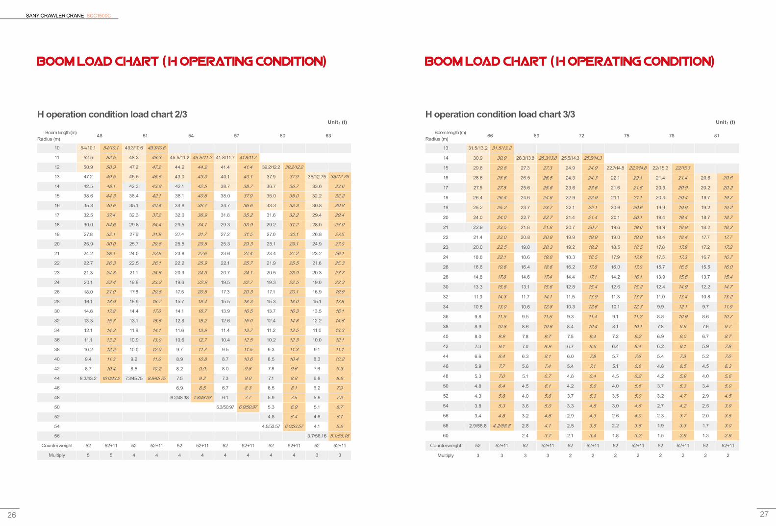
Boom load chart ( H operating condition)
H operation condition load chart 2/3
Boom length (m)Radius (m)
48 51 54 57 60 63
10 54/10.1 54/10.1 49.3/10.6 49.3/10.6
11 52.5 52.5 48.3 48.3 45.5/11.2 45.5/11.2 41.8/11.7 41.8/11.7
12 50.9 50.9 47.2 47.2 44.2 44.2 41.4 41.4 39.2/12.2 39.2/12.2
13 47.2 49.5 45.5 45.5 43.0 43.0 40.1 40.1 37.9 37.9 35/12.75 35/12.75
14 42.5 48.1 42.3 43.8 42.1 42.5 38.7 38.7 36.7 36.7 33.6 33.6
15 38.6 44.3 38.4 42.1 38.1 40.6 38.0 37.9 35.0 35.0 32.2 32.2
16 35.3 40.6 35.1 40.4 34.8 38.7 34.7 36.6 33.3 33.3 30.8 30.8
17 32.5 37.4 32.3 37.2 32.0 36.9 31.8 35.2 31.6 32.2 29.4 29.4
18 30.0 34.6 29.8 34.4 29.5 34.1 29.3 33.9 29.2 31.2 28.0 28.0
19 27.8 32.1 27.6 31.9 27.4 31.7 27.2 31.5 27.0 30.1 26.8 27.5
20 25.9 30.0 25.7 29.8 25.5 29.5 25.3 29.3 25.1 29.1 24.9 27.0
21 24.2 28.1 24.0 27.9 23.8 27.6 23.6 27.4 23.4 27.2 23.2 26.1
22 22.7 26.3 22.5 26.1 22.2 25.9 22.1 25.7 21.9 25.5 21.6 25.3
23 21.3 24.8 21.1 24.6 20.9 24.3 20.7 24.1 20.5 23.9 20.3 23.7
24 20.1 23.4 19.9 23.2 19.6 22.9 19.5 22.7 19.3 22.5 19.0 22.3
26 18.0 21.0 17.8 20.8 17.5 20.5 17.3 20.3 17.1 20.1 16.9 19.9
28 16.1 18.9 15.9 18.7 15.7 18.4 15.5 18.3 15.3 18.0 15.1 17.8
30 14.6 17.2 14.4 17.0 14.1 16.7 13.9 16.5 13.7 16.3 13.5 16.1
32 13.3 15.7 13.1 15.5 12.8 15.2 12.6 15.0 12.4 14.8 12.2 14.6
34 12.1 14.3 11.9 14.1 11.6 13.9 11.4 13.7 11.2 13.5 11.0 13.3
36 11.1 13.2 10.9 13.0 10.6 12.7 10.4 12.5 10.2 12.3 10.0 12.1
38 10.2 12.2 10.0 12.0 9.7 11.7 9.5 11.5 9.3 11.3 9.1 11.1
40 9.4 11.3 9.2 11.0 8.9 10.8 8.7 10.6 8.5 10.4 8.3 10.2
42 8.7 10.4 8.5 10.2 8.2 9.9 8.0 9.8 7.8 9.6 7.6 9.3
44 8.3/43.2 10.0/43.2 7.3/45.75 8.9/45.75 7.5 9.2 7.3 9.0 7.1 8.8 6.8 8.6
46 6.9 8.5 6.7 8.3 6.5 8.1 6.2 7.9
48 6.2/48.38 7.8/48.38 6.1 7.7 5.9 7.5 5.6 7.3
50 5.3/50.97 6.9/50.97 5.3 6.9 5.1 6.7
52 4.8 6.4 4.6 6.1
54 4.5/53.57 6.0/53.57 4.1 5.6
56 3.7/56.16 5.1/56.16
Counterweight 52 52+11 52 52+11 52 52+11 52 52+11 52 52+11 52 52+11
Multiply 5 5 4 4 4 4 4 4 4 4 3 3
Unit:(t)
Boom load chart ( H operating condition)
H operation condition load chart 3/3
Boom length (m)Radius (m)
66 69 72 75 78 81
13 31.5/13.2 31.5/13.2
14 30.9 30.9 28.3/13.8 28.3/13.8 25.5/14.3 25.5/14.3
15 29.8 29.8 27.3 27.3 24.9 24.9 22.7/14.8 22.7/14.8 22/15.3 22/15.3
16 28.6 28.6 26.5 26.5 24.3 24.3 22.1 22.1 21.4 21.4 20.6 20.6
17 27.5 27.5 25.6 25.6 23.6 23.6 21.6 21.6 20.9 20.9 20.2 20.2
18 26.4 26.4 24.6 24.6 22.9 22.9 21.1 21.1 20.4 20.4 19.7 19.7
19 25.2 25.2 23.7 23.7 22.1 22.1 20.6 20.6 19.9 19.9 19.2 19.2
20 24.0 24.0 22.7 22.7 21.4 21.4 20.1 20.1 19.4 19.4 18.7 18.7
21 22.9 23.5 21.8 21.8 20.7 20.7 19.6 19.6 18.9 18.9 18.2 18.2
22 21.4 23.0 20.8 20.8 19.9 19.9 19.0 19.0 18.4 18.4 17.7 17.7
23 20.0 22.5 19.8 20.3 19.2 19.2 18.5 18.5 17.8 17.8 17.2 17.2
24 18.8 22.1 18.6 19.8 18.3 18.5 17.9 17.9 17.3 17.3 16.7 16.7
26 16.6 19.6 16.4 18.6 16.2 17.8 16.0 17.0 15.7 16.5 15.5 16.0
28 14.8 17.6 14.6 17.4 14.4 17.1 14.2 16.1 13.9 15.6 13.7 15.4
30 13.3 15.8 13.1 15.6 12.8 15.4 12.6 15.2 12.4 14.9 12.2 14.7
32 11.9 14.3 11.7 14.1 11.5 13.9 11.3 13.7 11.0 13.4 10.8 13.2
34 10.8 13.0 10.6 12.8 10.3 12.6 10.1 12.3 9.9 12.1 9.7 11.9
36 9.8 11.9 9.5 11.6 9.3 11.4 9.1 11.2 8.8 10.9 8.6 10.7
38 8.9 10.8 8.6 10.6 8.4 10.4 8.1 10.1 7.8 9.9 7.6 9.7
40 8.0 9.9 7.8 9.7 7.5 9.4 7.2 9.2 6.9 9.0 6.7 8.7
42 7.3 9.1 7.0 8.9 6.7 8.6 6.4 8.4 6.2 8.1 5.9 7.8
44 6.6 8.4 6.3 8.1 6.0 7.8 5.7 7.6 5.4 7.3 5.2 7.0
46 5.9 7.7 5.6 7.4 5.4 7.1 5.1 6.8 4.8 6.5 4.5 6.3
48 5.3 7.0 5.1 6.7 4.8 6.4 4.5 6.2 4.2 5.9 4.0 5.6
50 4.8 6.4 4.5 6.1 4.2 5.8 4.0 5.6 3.7 5.3 3.4 5.0
52 4.3 5.8 4.0 5.6 3.7 5.3 3.5 5.0 3.2 4.7 2.9 4.5
54 3.8 5.3 3.6 5.0 3.3 4.8 3.0 4.5 2.7 4.2 2.5 3.9
56 3.4 4.8 3.2 4.6 2.9 4.3 2.6 4.0 2.3 3.7 2.0 3.5
58 2.9/58.8 4.2/58.8 2.8 4.1 2.5 3.8 2.2 3.6 1.9 3.3 1.7 3.0
60 2.4 3.7 2.1 3.4 1.8 3.2 1.5 2.9 1.3 2.6
Counterweight 52 52+11 52 52+11 52 52+11 52 52+11 52 52+11 52 52+11
Multiply 3 3 3 3 2 2 2 2 2 2 2 2
Unit:(t)
SANY CRAWLER CRANE SCC1500C
28 29
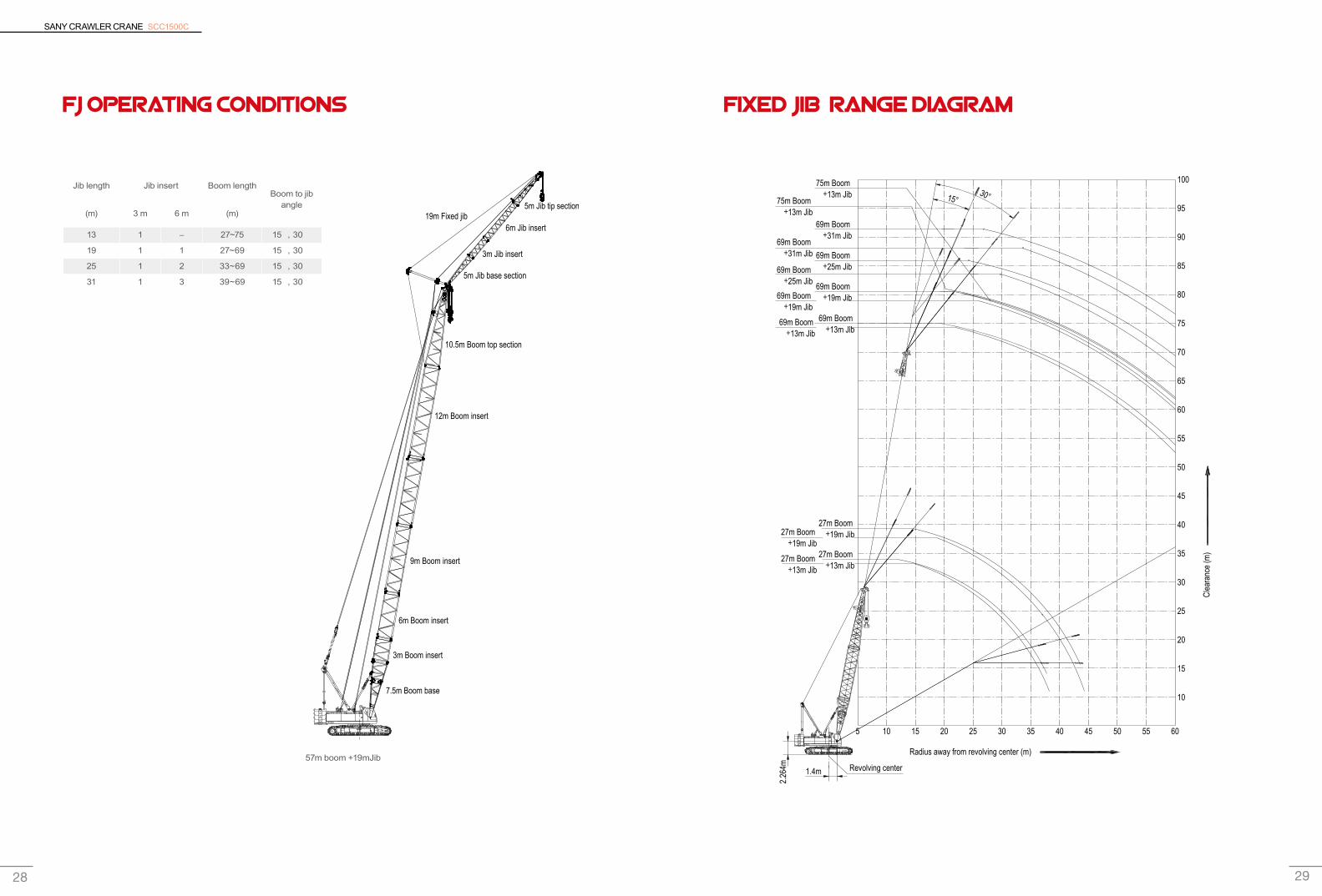
FJ operating conditions
Jib length Jib insert Boom lengthBoom to jib
angle(m) 3 m 6 m (m)
13 1 - 27~75 15°,30°
19 1 1 27~69 15°,30°
25 1 2 33~69 15°,30°
31 1 3 39~69 15°,30°
FIXED JIB RANGE DIAGRAM
19m Fixed jib
12m Boom insert
9m Boom insert
6m Boom insert
3m Boom insert
7.5m Boom base
3m Jib insert
6m Jib insert
5m Jib base section
10.5m Boom top section
5m Jib tip section
100
95
90
85
80
75
70
65
60
55
50
45
40
35
30
25
20
15
10
1.4m2.
264m
10 20 30 40155 5025 35 5545 60
75m Boom +13m Jib
75m Boom +13m Jib
69m Boom +31m Jib
69m Boom +31m Jib 69m Boom
+25m Jib69m Boom +25m Jib 69m Boom
+19m Jib
69m Boom +13m Jib
27m Boom +19m Jib27m Boom
+19m Jib27m Boom
+13m Jib27m Boom
+13m Jib
69m Boom +13m Jib
69m Boom +19m Jib
30°15°
Clea
ranc
e (m
)
Radius away from revolving center (m)
Revolving center57m boom +19mJib
SANY CRAWLER CRANE SCC1500C
30 31
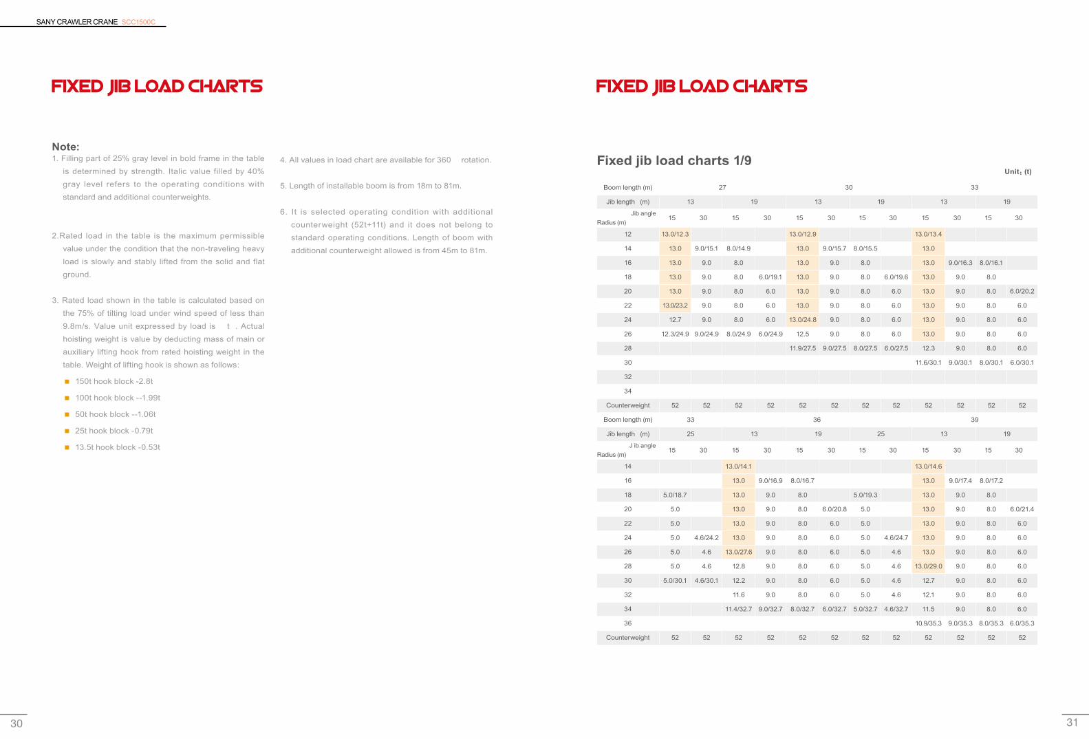
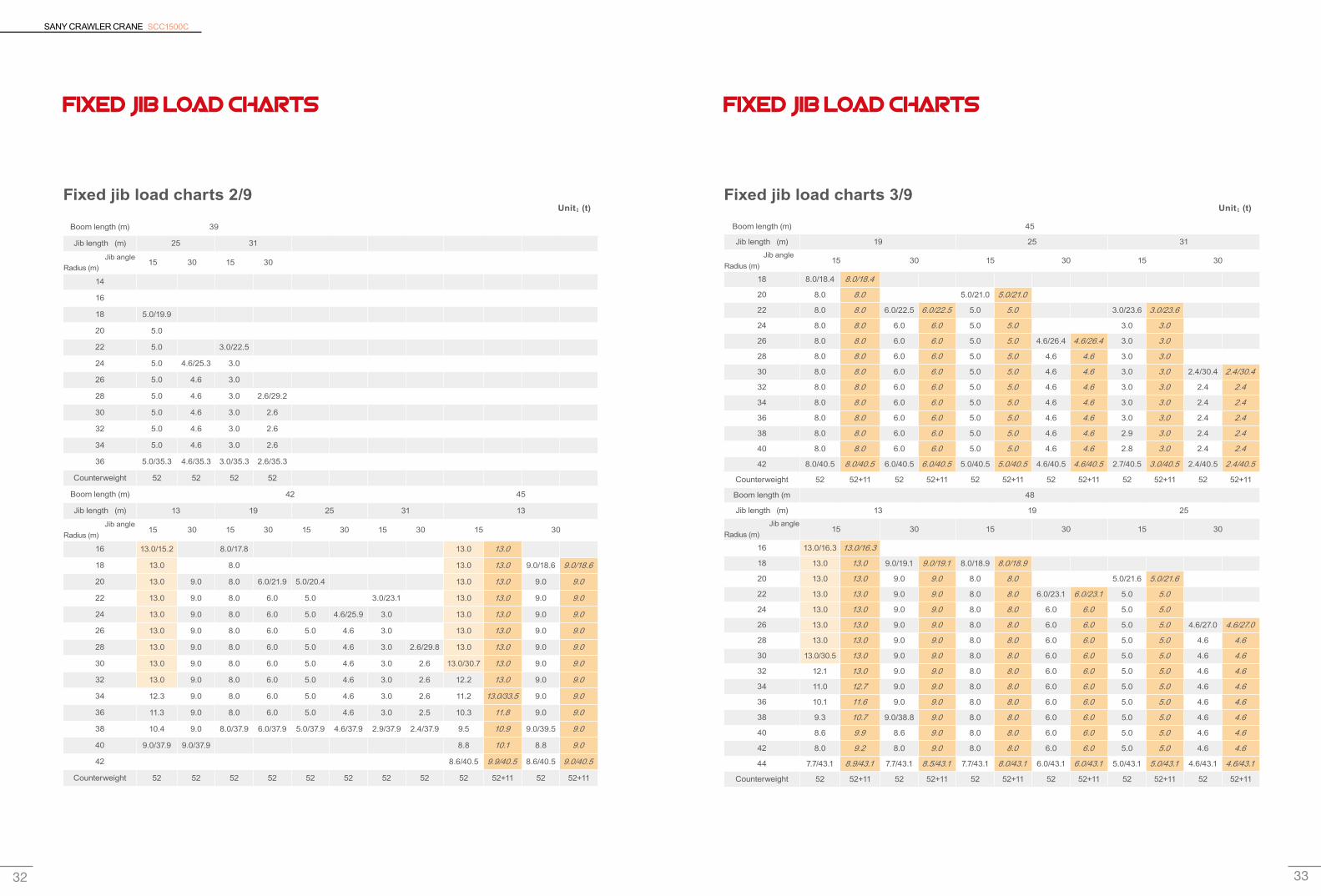
FIXED JIB LOAD CHARTS
Note:1. Filling part of 25% gray level in bold frame in the table
is determined by strength. Italic value filled by 40% gray level refers to the operating conditions with standard and additional counterweights.
2.Rated load in the table is the maximum permissible value under the condition that the non-traveling heavy load is slowly and stably lifted from the solid and flat ground.
3. Rated load shown in the table is calculated based on the 75% of tilting load under wind speed of less than 9.8m/s. Value unit expressed by load is “t”. Actual hoisting weight is value by deducting mass of main or auxiliary lifting hook from rated hoisting weight in the table. Weight of lifting hook is shown as follows:
150t hook block -2.8t ■
100t hook block --1.99t ■
50t hook block --1.06t ■
25t hook block -0.79t ■
13.5t hook block -0.53t ■
4. All values in load chart are available for 360° rotation.
5. Length of installable boom is from 18m to 81m.
6. It is selected operating condition with additional counterweight (52t+11t) and it does not belong to standard operating conditions. Length of boom with additional counterweight allowed is from 45m to 81m.
FIXED JIB LOAD CHARTS
Fixed jib load charts 1/9
Boom length (m) 27 30 33
Jib length (m) 13 19 13 19 13 19
Jib angle Radius (m)
15° 30° 15° 30° 15° 30° 15° 30° 15° 30° 15° 30°
12 13.0/12.3 13.0/12.9 13.0/13.4
14 13.0 9.0/15.1 8.0/14.9 13.0 9.0/15.7 8.0/15.5 13.0
16 13.0 9.0 8.0 13.0 9.0 8.0 13.0 9.0/16.3 8.0/16.1
18 13.0 9.0 8.0 6.0/19.1 13.0 9.0 8.0 6.0/19.6 13.0 9.0 8.0
20 13.0 9.0 8.0 6.0 13.0 9.0 8.0 6.0 13.0 9.0 8.0 6.0/20.2
22 13.0/23.2 9.0 8.0 6.0 13.0 9.0 8.0 6.0 13.0 9.0 8.0 6.0
24 12.7 9.0 8.0 6.0 13.0/24.8 9.0 8.0 6.0 13.0 9.0 8.0 6.0
26 12.3/24.9 9.0/24.9 8.0/24.9 6.0/24.9 12.5 9.0 8.0 6.0 13.0 9.0 8.0 6.0
28 11.9/27.5 9.0/27.5 8.0/27.5 6.0/27.5 12.3 9.0 8.0 6.0
30 11.6/30.1 9.0/30.1 8.0/30.1 6.0/30.1
32
34
Counterweight 52 52 52 52 52 52 52 52 52 52 52 52
Boom length (m) 33 36 39
Jib length (m) 25 13 19 25 13 19
J ib angle Radius (m)
15° 30° 15° 30° 15° 30° 15° 30° 15° 30° 15° 30°
14 13.0/14.1 13.0/14.6
16 13.0 9.0/16.9 8.0/16.7 13.0 9.0/17.4 8.0/17.2
18 5.0/18.7 13.0 9.0 8.0 5.0/19.3 13.0 9.0 8.0
20 5.0 13.0 9.0 8.0 6.0/20.8 5.0 13.0 9.0 8.0 6.0/21.4
22 5.0 13.0 9.0 8.0 6.0 5.0 13.0 9.0 8.0 6.0
24 5.0 4.6/24.2 13.0 9.0 8.0 6.0 5.0 4.6/24.7 13.0 9.0 8.0 6.0
26 5.0 4.6 13.0/27.6 9.0 8.0 6.0 5.0 4.6 13.0 9.0 8.0 6.0
28 5.0 4.6 12.8 9.0 8.0 6.0 5.0 4.6 13.0/29.0 9.0 8.0 6.0
30 5.0/30.1 4.6/30.1 12.2 9.0 8.0 6.0 5.0 4.6 12.7 9.0 8.0 6.0
32 11.6 9.0 8.0 6.0 5.0 4.6 12.1 9.0 8.0 6.0
34 11.4/32.7 9.0/32.7 8.0/32.7 6.0/32.7 5.0/32.7 4.6/32.7 11.5 9.0 8.0 6.0
36 10.9/35.3 9.0/35.3 8.0/35.3 6.0/35.3
Counterweight 52 52 52 52 52 52 52 52 52 52 52 52
Unit:(t)
SANY CRAWLER CRANE SCC1500C
32 33
FIXED JIB LOAD CHARTS
Fixed jib load charts 2/9
Boom length (m) 39
Jib length (m) 25 31
Jib angle Radius (m)
15° 30° 15° 30°
14
16
18 5.0/19.9
20 5.0
22 5.0 3.0/22.5
24 5.0 4.6/25.3 3.0
26 5.0 4.6 3.0
28 5.0 4.6 3.0 2.6/29.2
30 5.0 4.6 3.0 2.6
32 5.0 4.6 3.0 2.6
34 5.0 4.6 3.0 2.6
36 5.0/35.3 4.6/35.3 3.0/35.3 2.6/35.3
Counterweight 52 52 52 52
Boom length (m) 42 45
Jib length (m) 13 19 25 31 13
Jib angle Radius (m)
15° 30° 15° 30° 15° 30° 15° 30° 15° 30°
16 13.0/15.2 8.0/17.8 13.0 13.0
18 13.0 8.0 13.0 13.0 9.0/18.6 9.0/18.6
20 13.0 9.0 8.0 6.0/21.9 5.0/20.4 13.0 13.0 9.0 9.0
22 13.0 9.0 8.0 6.0 5.0 3.0/23.1 13.0 13.0 9.0 9.0
24 13.0 9.0 8.0 6.0 5.0 4.6/25.9 3.0 13.0 13.0 9.0 9.0
26 13.0 9.0 8.0 6.0 5.0 4.6 3.0 13.0 13.0 9.0 9.0
28 13.0 9.0 8.0 6.0 5.0 4.6 3.0 2.6/29.8 13.0 13.0 9.0 9.0
30 13.0 9.0 8.0 6.0 5.0 4.6 3.0 2.6 13.0/30.7 13.0 9.0 9.0
32 13.0 9.0 8.0 6.0 5.0 4.6 3.0 2.6 12.2 13.0 9.0 9.0
34 12.3 9.0 8.0 6.0 5.0 4.6 3.0 2.6 11.2 13.0/33.5 9.0 9.0
36 11.3 9.0 8.0 6.0 5.0 4.6 3.0 2.5 10.3 11.8 9.0 9.0
38 10.4 9.0 8.0/37.9 6.0/37.9 5.0/37.9 4.6/37.9 2.9/37.9 2.4/37.9 9.5 10.9 9.0/39.5 9.0
40 9.0/37.9 9.0/37.9 8.8 10.1 8.8 9.0
42 8.6/40.5 9.9/40.5 8.6/40.5 9.0/40.5
Counterweight 52 52 52 52 52 52 52 52 52 52+11 52 52+11
Unit:(t)
FIXED JIB LOAD CHARTS
Fixed jib load charts 3/9
Boom length (m) 45
Jib length (m) 19 25 31 Jib angle Radius (m)
15° 30° 15° 30° 15° 30°
18 8.0/18.4 8.0/18.4
20 8.0 8.0 5.0/21.0 5.0/21.0
22 8.0 8.0 6.0/22.5 6.0/22.5 5.0 5.0 3.0/23.6 3.0/23.6
24 8.0 8.0 6.0 6.0 5.0 5.0 3.0 3.0
26 8.0 8.0 6.0 6.0 5.0 5.0 4.6/26.4 4.6/26.4 3.0 3.0
28 8.0 8.0 6.0 6.0 5.0 5.0 4.6 4.6 3.0 3.0
30 8.0 8.0 6.0 6.0 5.0 5.0 4.6 4.6 3.0 3.0 2.4/30.4 2.4/30.4
32 8.0 8.0 6.0 6.0 5.0 5.0 4.6 4.6 3.0 3.0 2.4 2.4
34 8.0 8.0 6.0 6.0 5.0 5.0 4.6 4.6 3.0 3.0 2.4 2.4
36 8.0 8.0 6.0 6.0 5.0 5.0 4.6 4.6 3.0 3.0 2.4 2.4
38 8.0 8.0 6.0 6.0 5.0 5.0 4.6 4.6 2.9 3.0 2.4 2.4
40 8.0 8.0 6.0 6.0 5.0 5.0 4.6 4.6 2.8 3.0 2.4 2.4
42 8.0/40.5 8.0/40.5 6.0/40.5 6.0/40.5 5.0/40.5 5.0/40.5 4.6/40.5 4.6/40.5 2.7/40.5 3.0/40.5 2.4/40.5 2.4/40.5
Counterweight 52 52+11 52 52+11 52 52+11 52 52+11 52 52+11 52 52+11
Boom length (m 48
Jib length (m) 13 19 25 Jib angle Radius (m)
15° 30° 15° 30° 15° 30°
16 13.0/16.3 13.0/16.3
18 13.0 13.0 9.0/19.1 9.0/19.1 8.0/18.9 8.0/18.9
20 13.0 13.0 9.0 9.0 8.0 8.0 5.0/21.6 5.0/21.6
22 13.0 13.0 9.0 9.0 8.0 8.0 6.0/23.1 6.0/23.1 5.0 5.0
24 13.0 13.0 9.0 9.0 8.0 8.0 6.0 6.0 5.0 5.0
26 13.0 13.0 9.0 9.0 8.0 8.0 6.0 6.0 5.0 5.0 4.6/27.0 4.6/27.0
28 13.0 13.0 9.0 9.0 8.0 8.0 6.0 6.0 5.0 5.0 4.6 4.6
30 13.0/30.5 13.0 9.0 9.0 8.0 8.0 6.0 6.0 5.0 5.0 4.6 4.6
32 12.1 13.0 9.0 9.0 8.0 8.0 6.0 6.0 5.0 5.0 4.6 4.6
34 11.0 12.7 9.0 9.0 8.0 8.0 6.0 6.0 5.0 5.0 4.6 4.6
36 10.1 11.6 9.0 9.0 8.0 8.0 6.0 6.0 5.0 5.0 4.6 4.6
38 9.3 10.7 9.0/38.8 9.0 8.0 8.0 6.0 6.0 5.0 5.0 4.6 4.6
40 8.6 9.9 8.6 9.0 8.0 8.0 6.0 6.0 5.0 5.0 4.6 4.6
42 8.0 9.2 8.0 9.0 8.0 8.0 6.0 6.0 5.0 5.0 4.6 4.6
44 7.7/43.1 8.9/43.1 7.7/43.1 8.5/43.1 7.7/43.1 8.0/43.1 6.0/43.1 6.0/43.1 5.0/43.1 5.0/43.1 4.6/43.1 4.6/43.1
Counterweight 52 52+11 52 52+11 52 52+11 52 52+11 52 52+11 52 52+11
Unit:(t)
SANY CRAWLER CRANE SCC1500C
34 35
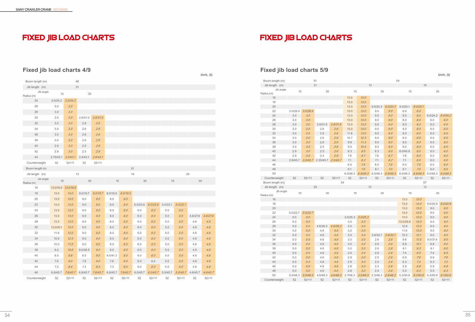
FIXED JIB LOAD CHARTS
Fixed jib load charts 4/9
Boom length (m) 48
Jib length (m) 31
Jib angle Radius (m)
15° 30°
24 3.0/24.2 3.0/24.2
26 3.0 3.0
28 3.0 3.0
30 3.0 3.0 2.6/31.0 2.6/31.0
32 3.0 3.0 2.6 2.6
34 3.0 3.0 2.6 2.6
36 3.0 3.0 2.6 2.6
38 3.0 3.0 2.6 2.6
40 2.9 3.0 2.5 2.6
42 2.8 3.0 2.5 2.6
44 2.75/43.1 3.0/43.1 2.4/43.1 2.6/43.1
Counterweight 52 52+11 52 52+11
Boom length (m 51
Jib length (m) 13 19 25
Jib angle Radius (m)
15° 30° 15° 30° 15° 30°
16 13.0/16.9 13.0/16.9
18 13.0 13.0 9.0/19.7 9.0/19.7 8.0/19.5 8.0/19.5
20 13.0 13.0 9.0 9.0 8.0 8.0
22 13.0 13.0 9.0 9.0 8.0 8.0 6.0/23.6 6.0/23.6 5.0/22.1 5.0/22.1
24 13.0 13.0 9.0 9.0 8.0 8.0 6.0 6.0 5.0 5.0
26 13.0 13.0 9.0 9.0 8.0 8.0 6.0 6.0 5.0 5.0 4.6/27.6 4.6/27.6
28 13.0 13.0 9.0 9.0 8.0 8.0 6.0 6.0 5.0 5.0 4.6 4.6
30 13.0/30.1 13.0 9.0 9.0 8.0 8.0 6.0 6.0 5.0 5.0 4.6 4.6
32 11.9 13.0 9.0 9.0 8.0 8.0 6.0 6.0 5.0 5.0 4.6 4.6
34 10.9 12.5 9.0 9.0 8.0 8.0 6.0 6.0 5.0 5.0 4.6 4.6
36 10.0 11.5 9.0 9.0 8.0 8.0 6.0 6.0 5.0 5.0 4.6 4.6
38 9.2 10.6 9.0/38.5 9.0 8.0 8.0 6.0 6.0 5.0 5.0 4.6 4.6
40 8.5 9.8 8.5 9.0 8.0/41.3 8.0 6.0 6.0 5.0 5.0 4.6 4.6
42 7.8 9.0 7.8 9.0 7.8 8.0 6.0 6.0 5.0 5.0 4.6 4.6
44 7.3 8.4 7.3 8.4 7.3 8.0 6.0 6.0 5.0 5.0 4.6 4.6
46 6.8/45.7 7.8/45.7 6.8/45.7 7.8/45.7 6.8/45.7 7.8/45.7 6.0/45.7 6.0/45.7 5.0/45.7 5.0/45.7 4.6/45.7 4.6/45.7
Counterweight 52 52+11 52 52+11 52 52+11 52 52+11 52 52+11 52 52+11
Unit:(t)
FIXED JIB LOAD CHARTS
Fixed jib load charts 5/9
Boom length (m) 51 54Jib length (m) 31 13 19
Jib angle Radius (m)
15° 30° 15° 30° 15° 30°
16 13.0 13.0 18 13.0 13.0 20 13.0 13.0 9.0/20.3 9.0/20.3 8.0/20.1 8.0/20.122 3.0/28.4 3.0/28.4 13.0 13.0 9.0 9.0 8.0 8.0 24 3.0 3.0 13.0 13.0 9.0 9.0 8.0 8.0 6.0/24.2 6.0/24.226 3.0 3.0 13.0 13.0 9.0 9.0 8.0 8.0 6.0 6.0 28 3.0 3.0 2.6/31.5 2.6/31.5 13.0 13.0 9.0 9.0 8.0 8.0 6.0 6.0 30 3.0 3.0 2.6 2.6 13.0 13.0 9.0 9.0 8.0 8.0 6.0 6.0 32 3.0 3.0 2.6 2.6 11.8 13.0 9.0 9.0 8.0 8.0 6.0 6.0 34 3.0 3.0 2.6 2.6 10.7 12.3 9.0 9.0 8.0 8.0 6.0 6.0 36 3.0 3.0 2.6 2.6 9.8 11.3 9.0 9.0 8.0 8.0 6.0 6.0 38 3.0 3.0 2.5 2.6 9.0 10.4 9.0 9.0 8.0 8.0 6.0 6.0 40 2.9 3.0 2.5 2.6 8.3 9.5 8.3 9.0 8.0/40.9 8.0 6.0 6.0 42 2.9 3.0 2.4 2.6 7.6 8.7 7.6 8.7 7.6 8.0 6.0 6.0 44 2.8/45.7 3.0/45.7 2.35/45.7 2.5/45.7 7.1 8.2 7.1 8.2 7.1 8.0 6.0 6.0 46 6.5 7.5 6.5 7.5 6.5 7.5 6.0 6.0 48 6.1 7.0 6.1 7.0 6.1 7.0 6.0 6.0 50 6.0/48.3 6.9/48.3 6.0/48.3 6.9/48.3 6.0/48.3 6.9/48.3 6.0/48.3 6.0/48.3
Counterweight 52 52+11 52 52+11 52 52+11 52 52+11 52 52+11 52 52+11Boom length (m) 54 57Jib length (m) 25 31 13
Jib angle Radius (m)
15° 30° 15° 30° 15° 30°
16 13.0 13.0 18 13.0 13.0 9.0/20.9 9.0/20.920 13.0 13.0 9.0 9.0 22 5.0/22.7 5.0/22.7 13.0 13.0 9.0 9.0 24 5.0 5.0 3.0/25.3 3.0/25.3 13.0 13.0 9.0 9.0 26 5.0 5.0 3.0 3.0 13.0/29.8 13.0 9.0 9.0 28 5.0 5.0 4.6/28.2 4.6/28.2 3.0 3.0 12.8 13.0 9.0 9.0 30 5.0 5.0 4.6 4.6 3.0 3.0 11.6 13.0 9.0 9.0 32 5.0 5.0 4.6 4.6 3.0 3.0 2.6/32.1 2.6/32.1 10.5 12.1 9.0 9.0 34 5.0 5.0 4.6 4.6 3.0 3.0 2.6 2.6 9.6 11.0 9.0/37.4 9.0 36 5.0 5.0 4.6 4.6 3.0 3.0 2.6 2.6 8.8 10.1 8.8 9.0 38 5.0 5.0 4.6 4.6 3.0 3.0 2.6 2.6 8.1 9.3 8.1 9.0 40 5.0 5.0 4.6 4.6 3.0 3.0 2.6 2.6 7.4 8.5 7.4 8.5 42 5.0 5.0 4.6 4.6 2.9 3.0 2.5 2.6 6.9 7.9 6.9 7.9 44 5.0 5.0 4.6 4.6 2.9 3.0 2.5 2.6 6.3 7.2 6.3 7.2 46 5.0 5.0 4.6 4.6 2.8 3.0 2.4 2.6 5.9 6.8 5.9 6.8 48 5.0 5.0 4.6 4.6 2.8 3.0 2.4 2.6 5.5 6.3 5.5 6.3 50 5.0/48.3 5.0/48.3 4.6/48.3 4.6/48.3 2.7/48.3 3.0/48.3 2.3/48.3 2.6/48.3 5.3/50.9 6.1/50.9 5.3/50.9 6.1/50.9
Counterweight 52 52+11 52 52+11 52 52+11 52 52+11 52 52+11 52 52+11
Unit:(t)
SANY CRAWLER CRANE SCC1500C
36 37
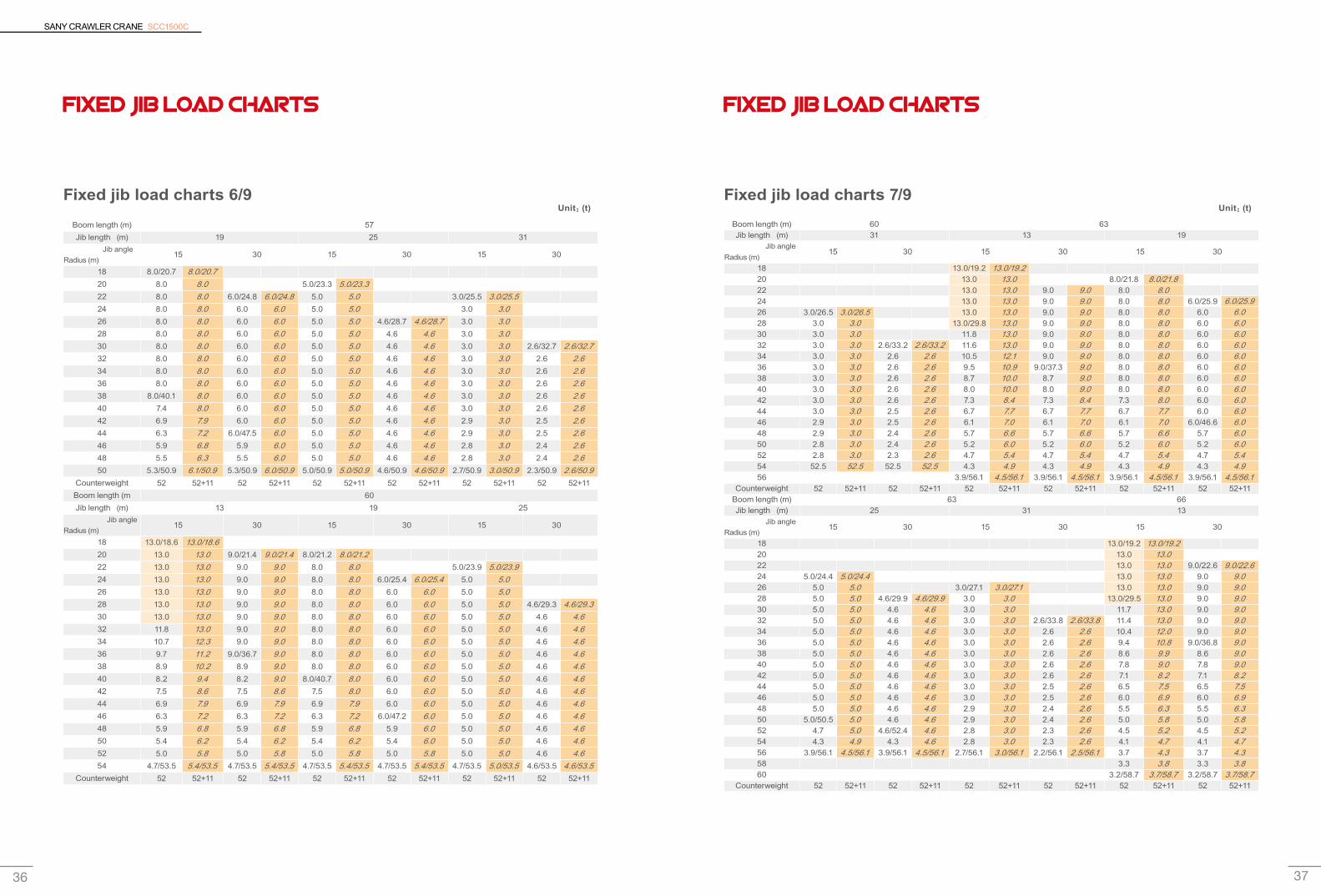
FIXED JIB LOAD CHARTS
Fixed jib load charts 6/9
Boom length (m) 57Jib length (m) 19 25 31
Jib angle Radius (m)
15° 30° 15° 30° 15° 30°
18 8.0/20.7 8.0/20.720 8.0 8.0 5.0/23.3 5.0/23.322 8.0 8.0 6.0/24.8 6.0/24.8 5.0 5.0 3.0/25.5 3.0/25.524 8.0 8.0 6.0 6.0 5.0 5.0 3.0 3.0 26 8.0 8.0 6.0 6.0 5.0 5.0 4.6/28.7 4.6/28.7 3.0 3.0 28 8.0 8.0 6.0 6.0 5.0 5.0 4.6 4.6 3.0 3.0 30 8.0 8.0 6.0 6.0 5.0 5.0 4.6 4.6 3.0 3.0 2.6/32.7 2.6/32.732 8.0 8.0 6.0 6.0 5.0 5.0 4.6 4.6 3.0 3.0 2.6 2.6 34 8.0 8.0 6.0 6.0 5.0 5.0 4.6 4.6 3.0 3.0 2.6 2.6 36 8.0 8.0 6.0 6.0 5.0 5.0 4.6 4.6 3.0 3.0 2.6 2.6 38 8.0/40.1 8.0 6.0 6.0 5.0 5.0 4.6 4.6 3.0 3.0 2.6 2.6 40 7.4 8.0 6.0 6.0 5.0 5.0 4.6 4.6 3.0 3.0 2.6 2.6 42 6.9 7.9 6.0 6.0 5.0 5.0 4.6 4.6 2.9 3.0 2.5 2.6 44 6.3 7.2 6.0/47.5 6.0 5.0 5.0 4.6 4.6 2.9 3.0 2.5 2.6 46 5.9 6.8 5.9 6.0 5.0 5.0 4.6 4.6 2.8 3.0 2.4 2.6 48 5.5 6.3 5.5 6.0 5.0 5.0 4.6 4.6 2.8 3.0 2.4 2.6 50 5.3/50.9 6.1/50.9 5.3/50.9 6.0/50.9 5.0/50.9 5.0/50.9 4.6/50.9 4.6/50.9 2.7/50.9 3.0/50.9 2.3/50.9 2.6/50.9
Counterweight 52 52+11 52 52+11 52 52+11 52 52+11 52 52+11 52 52+11Boom length (m 60Jib length (m) 13 19 25
Jib angle Radius (m)
15° 30° 15° 30° 15° 30°
18 13.0/18.6 13.0/18.620 13.0 13.0 9.0/21.4 9.0/21.4 8.0/21.2 8.0/21.222 13.0 13.0 9.0 9.0 8.0 8.0 5.0/23.9 5.0/23.924 13.0 13.0 9.0 9.0 8.0 8.0 6.0/25.4 6.0/25.4 5.0 5.0 26 13.0 13.0 9.0 9.0 8.0 8.0 6.0 6.0 5.0 5.0 28 13.0 13.0 9.0 9.0 8.0 8.0 6.0 6.0 5.0 5.0 4.6/29.3 4.6/29.330 13.0 13.0 9.0 9.0 8.0 8.0 6.0 6.0 5.0 5.0 4.6 4.6 32 11.8 13.0 9.0 9.0 8.0 8.0 6.0 6.0 5.0 5.0 4.6 4.6 34 10.7 12.3 9.0 9.0 8.0 8.0 6.0 6.0 5.0 5.0 4.6 4.6 36 9.7 11.2 9.0/36.7 9.0 8.0 8.0 6.0 6.0 5.0 5.0 4.6 4.6 38 8.9 10.2 8.9 9.0 8.0 8.0 6.0 6.0 5.0 5.0 4.6 4.6 40 8.2 9.4 8.2 9.0 8.0/40.7 8.0 6.0 6.0 5.0 5.0 4.6 4.6 42 7.5 8.6 7.5 8.6 7.5 8.0 6.0 6.0 5.0 5.0 4.6 4.6 44 6.9 7.9 6.9 7.9 6.9 7.9 6.0 6.0 5.0 5.0 4.6 4.6 46 6.3 7.2 6.3 7.2 6.3 7.2 6.0/47.2 6.0 5.0 5.0 4.6 4.6 48 5.9 6.8 5.9 6.8 5.9 6.8 5.9 6.0 5.0 5.0 4.6 4.6 50 5.4 6.2 5.4 6.2 5.4 6.2 5.4 6.0 5.0 5.0 4.6 4.6 52 5.0 5.8 5.0 5.8 5.0 5.8 5.0 5.8 5.0 5.0 4.6 4.6 54 4.7/53.5 5.4/53.5 4.7/53.5 5.4/53.5 4.7/53.5 5.4/53.5 4.7/53.5 5.4/53.5 4.7/53.5 5.0/53.5 4.6/53.5 4.6/53.5
Counterweight 52 52+11 52 52+11 52 52+11 52 52+11 52 52+11 52 52+11
Unit:(t)
FIXED JIB LOAD CHARTS
Fixed jib load charts 7/9Boom length (m) 60 63Jib length (m) 31 13 19
Jib angle Radius (m)
15° 30° 15° 30° 15° 30°
18 13.0/19.2 13.0/19.220 13.0 13.0 8.0/21.8 8.0/21.822 13.0 13.0 9.0 9.0 8.0 8.0 24 13.0 13.0 9.0 9.0 8.0 8.0 6.0/25.9 6.0/25.926 3.0/26.5 3.0/26.5 13.0 13.0 9.0 9.0 8.0 8.0 6.0 6.0 28 3.0 3.0 13.0/29.8 13.0 9.0 9.0 8.0 8.0 6.0 6.0 30 3.0 3.0 11.8 13.0 9.0 9.0 8.0 8.0 6.0 6.0 32 3.0 3.0 2.6/33.2 2.6/33.2 11.6 13.0 9.0 9.0 8.0 8.0 6.0 6.0 34 3.0 3.0 2.6 2.6 10.5 12.1 9.0 9.0 8.0 8.0 6.0 6.0 36 3.0 3.0 2.6 2.6 9.5 10.9 9.0/37.3 9.0 8.0 8.0 6.0 6.0 38 3.0 3.0 2.6 2.6 8.7 10.0 8.7 9.0 8.0 8.0 6.0 6.0 40 3.0 3.0 2.6 2.6 8.0 10.0 8.0 9.0 8.0 8.0 6.0 6.0 42 3.0 3.0 2.6 2.6 7.3 8.4 7.3 8.4 7.3 8.0 6.0 6.0 44 3.0 3.0 2.5 2.6 6.7 7.7 6.7 7.7 6.7 7.7 6.0 6.0 46 2.9 3.0 2.5 2.6 6.1 7.0 6.1 7.0 6.1 7.0 6.0/46.6 6.0 48 2.9 3.0 2.4 2.6 5.7 6.6 5.7 6.6 5.7 6.6 5.7 6.0 50 2.8 3.0 2.4 2.6 5.2 6.0 5.2 6.0 5.2 6.0 5.2 6.0 52 2.8 3.0 2.3 2.6 4.7 5.4 4.7 5.4 4.7 5.4 4.7 5.4 54 52.5 52.5 52.5 52.5 4.3 4.9 4.3 4.9 4.3 4.9 4.3 4.9 56 3.9/56.1 4.5/56.1 3.9/56.1 4.5/56.1 3.9/56.1 4.5/56.1 3.9/56.1 4.5/56.1
Counterweight 52 52+11 52 52+11 52 52+11 52 52+11 52 52+11 52 52+11Boom length (m) 63 66Jib length (m) 25 31 13
Jib angle Radius (m)
15° 30° 15° 30° 15° 30°
18 13.0/19.2 13.0/19.220 13.0 13.0 22 13.0 13.0 9.0/22.6 9.0/22.624 5.0/24.4 5.0/24.4 13.0 13.0 9.0 9.0 26 5.0 5.0 3.0/27.1 3.0/27.1 13.0 13.0 9.0 9.0 28 5.0 5.0 4.6/29.9 4.6/29.9 3.0 3.0 13.0/29.5 13.0 9.0 9.0 30 5.0 5.0 4.6 4.6 3.0 3.0 11.7 13.0 9.0 9.0 32 5.0 5.0 4.6 4.6 3.0 3.0 2.6/33.8 2.6/33.8 11.4 13.0 9.0 9.0 34 5.0 5.0 4.6 4.6 3.0 3.0 2.6 2.6 10.4 12.0 9.0 9.0 36 5.0 5.0 4.6 4.6 3.0 3.0 2.6 2.6 9.4 10.8 9.0/36.8 9.0 38 5.0 5.0 4.6 4.6 3.0 3.0 2.6 2.6 8.6 9.9 8.6 9.0 40 5.0 5.0 4.6 4.6 3.0 3.0 2.6 2.6 7.8 9.0 7.8 9.0 42 5.0 5.0 4.6 4.6 3.0 3.0 2.6 2.6 7.1 8.2 7.1 8.2 44 5.0 5.0 4.6 4.6 3.0 3.0 2.5 2.6 6.5 7.5 6.5 7.5 46 5.0 5.0 4.6 4.6 3.0 3.0 2.5 2.6 6.0 6.9 6.0 6.9 48 5.0 5.0 4.6 4.6 2.9 3.0 2.4 2.6 5.5 6.3 5.5 6.3 50 5.0/50.5 5.0 4.6 4.6 2.9 3.0 2.4 2.6 5.0 5.8 5.0 5.8 52 4.7 5.0 4.6/52.4 4.6 2.8 3.0 2.3 2.6 4.5 5.2 4.5 5.2 54 4.3 4.9 4.3 4.6 2.8 3.0 2.3 2.6 4.1 4.7 4.1 4.7 56 3.9/56.1 4.5/56.1 3.9/56.1 4.5/56.1 2.7/56.1 3.0/56.1 2.2/56.1 2.5/56.1 3.7 4.3 3.7 4.3 58 3.3 3.8 3.3 3.8 60 3.2/58.7 3.7/58.7 3.2/58.7 3.7/58.7
Counterweight 52 52+11 52 52+11 52 52+11 52 52+11 52 52+11 52 52+11
Unit:(t)
SANY CRAWLER CRANE SCC1500C
38 39
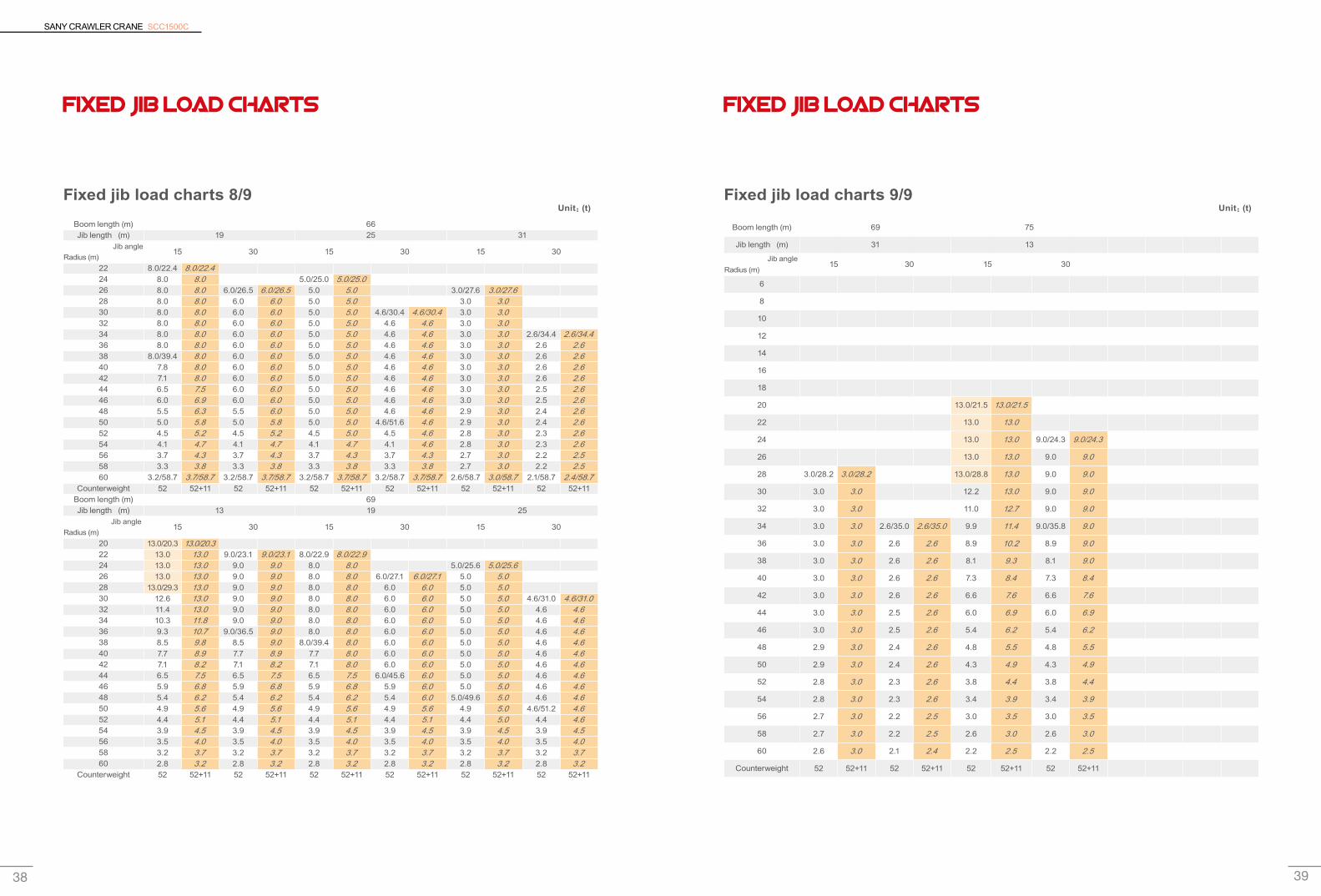
FIXED JIB LOAD CHARTS
Fixed jib load charts 8/9Boom length (m) 66Jib length (m) 19 25 31
Jib angle Radius (m)
15° 30° 15° 30° 15° 30°
22 8.0/22.4 8.0/22.424 8.0 8.0 5.0/25.0 5.0/25.026 8.0 8.0 6.0/26.5 6.0/26.5 5.0 5.0 3.0/27.6 3.0/27.628 8.0 8.0 6.0 6.0 5.0 5.0 3.0 3.0 30 8.0 8.0 6.0 6.0 5.0 5.0 4.6/30.4 4.6/30.4 3.0 3.0 32 8.0 8.0 6.0 6.0 5.0 5.0 4.6 4.6 3.0 3.0 34 8.0 8.0 6.0 6.0 5.0 5.0 4.6 4.6 3.0 3.0 2.6/34.4 2.6/34.436 8.0 8.0 6.0 6.0 5.0 5.0 4.6 4.6 3.0 3.0 2.6 2.6 38 8.0/39.4 8.0 6.0 6.0 5.0 5.0 4.6 4.6 3.0 3.0 2.6 2.6 40 7.8 8.0 6.0 6.0 5.0 5.0 4.6 4.6 3.0 3.0 2.6 2.6 42 7.1 8.0 6.0 6.0 5.0 5.0 4.6 4.6 3.0 3.0 2.6 2.6 44 6.5 7.5 6.0 6.0 5.0 5.0 4.6 4.6 3.0 3.0 2.5 2.6 46 6.0 6.9 6.0 6.0 5.0 5.0 4.6 4.6 3.0 3.0 2.5 2.6 48 5.5 6.3 5.5 6.0 5.0 5.0 4.6 4.6 2.9 3.0 2.4 2.6 50 5.0 5.8 5.0 5.8 5.0 5.0 4.6/51.6 4.6 2.9 3.0 2.4 2.6 52 4.5 5.2 4.5 5.2 4.5 5.0 4.5 4.6 2.8 3.0 2.3 2.6 54 4.1 4.7 4.1 4.7 4.1 4.7 4.1 4.6 2.8 3.0 2.3 2.6 56 3.7 4.3 3.7 4.3 3.7 4.3 3.7 4.3 2.7 3.0 2.2 2.5 58 3.3 3.8 3.3 3.8 3.3 3.8 3.3 3.8 2.7 3.0 2.2 2.5 60 3.2/58.7 3.7/58.7 3.2/58.7 3.7/58.7 3.2/58.7 3.7/58.7 3.2/58.7 3.7/58.7 2.6/58.7 3.0/58.7 2.1/58.7 2.4/58.7
Counterweight 52 52+11 52 52+11 52 52+11 52 52+11 52 52+11 52 52+11Boom length (m) 69Jib length (m) 13 19 25
Jib angle Radius (m)
15° 30° 15° 30° 15° 30°
20 13.0/20.3 13.0/20.322 13.0 13.0 9.0/23.1 9.0/23.1 8.0/22.9 8.0/22.924 13.0 13.0 9.0 9.0 8.0 8.0 5.0/25.6 5.0/25.626 13.0 13.0 9.0 9.0 8.0 8.0 6.0/27.1 6.0/27.1 5.0 5.0 28 13.0/29.3 13.0 9.0 9.0 8.0 8.0 6.0 6.0 5.0 5.0 30 12.6 13.0 9.0 9.0 8.0 8.0 6.0 6.0 5.0 5.0 4.6/31.0 4.6/31.032 11.4 13.0 9.0 9.0 8.0 8.0 6.0 6.0 5.0 5.0 4.6 4.6 34 10.3 11.8 9.0 9.0 8.0 8.0 6.0 6.0 5.0 5.0 4.6 4.6 36 9.3 10.7 9.0/36.5 9.0 8.0 8.0 6.0 6.0 5.0 5.0 4.6 4.6 38 8.5 9.8 8.5 9.0 8.0/39.4 8.0 6.0 6.0 5.0 5.0 4.6 4.6 40 7.7 8.9 7.7 8.9 7.7 8.0 6.0 6.0 5.0 5.0 4.6 4.6 42 7.1 8.2 7.1 8.2 7.1 8.0 6.0 6.0 5.0 5.0 4.6 4.6 44 6.5 7.5 6.5 7.5 6.5 7.5 6.0/45.6 6.0 5.0 5.0 4.6 4.6 46 5.9 6.8 5.9 6.8 5.9 6.8 5.9 6.0 5.0 5.0 4.6 4.6 48 5.4 6.2 5.4 6.2 5.4 6.2 5.4 6.0 5.0/49.6 5.0 4.6 4.6 50 4.9 5.6 4.9 5.6 4.9 5.6 4.9 5.6 4.9 5.0 4.6/51.2 4.6 52 4.4 5.1 4.4 5.1 4.4 5.1 4.4 5.1 4.4 5.0 4.4 4.6 54 3.9 4.5 3.9 4.5 3.9 4.5 3.9 4.5 3.9 4.5 3.9 4.5 56 3.5 4.0 3.5 4.0 3.5 4.0 3.5 4.0 3.5 4.0 3.5 4.0 58 3.2 3.7 3.2 3.7 3.2 3.7 3.2 3.7 3.2 3.7 3.2 3.7 60 2.8 3.2 2.8 3.2 2.8 3.2 2.8 3.2 2.8 3.2 2.8 3.2
Counterweight 52 52+11 52 52+11 52 52+11 52 52+11 52 52+11 52 52+11
Unit:(t)
FIXED JIB LOAD CHARTS
Fixed jib load charts 9/9
Boom length (m) 69 75
Jib length (m) 31 13
Jib angle Radius (m)
15° 30° 15° 30°
6
8
10
12
14
16
18
20 13.0/21.5 13.0/21.5
22 13.0 13.0
24 13.0 13.0 9.0/24.3 9.0/24.3
26 13.0 13.0 9.0 9.0
28 3.0/28.2 3.0/28.2 13.0/28.8 13.0 9.0 9.0
30 3.0 3.0 12.2 13.0 9.0 9.0
32 3.0 3.0 11.0 12.7 9.0 9.0
34 3.0 3.0 2.6/35.0 2.6/35.0 9.9 11.4 9.0/35.8 9.0
36 3.0 3.0 2.6 2.6 8.9 10.2 8.9 9.0
38 3.0 3.0 2.6 2.6 8.1 9.3 8.1 9.0
40 3.0 3.0 2.6 2.6 7.3 8.4 7.3 8.4
42 3.0 3.0 2.6 2.6 6.6 7.6 6.6 7.6
44 3.0 3.0 2.5 2.6 6.0 6.9 6.0 6.9
46 3.0 3.0 2.5 2.6 5.4 6.2 5.4 6.2
48 2.9 3.0 2.4 2.6 4.8 5.5 4.8 5.5
50 2.9 3.0 2.4 2.6 4.3 4.9 4.3 4.9
52 2.8 3.0 2.3 2.6 3.8 4.4 3.8 4.4
54 2.8 3.0 2.3 2.6 3.4 3.9 3.4 3.9
56 2.7 3.0 2.2 2.5 3.0 3.5 3.0 3.5
58 2.7 3.0 2.2 2.5 2.6 3.0 2.6 3.0
60 2.6 3.0 2.1 2.4 2.2 2.5 2.2 2.5
Counterweight 52 52+11 52 52+11 52 52+11 52 52+11
Unit:(t)

Quality Changes the World