Embed Size (px)
Citation preview
2010 JULY/AUGUST
In this issue ...
www.microwavers.org
• Noise source calibration • Breakfast in East Anglia • Lidl LNB mod for 10GHz
preamp use • Network Day for ATV • Recycling 900MHz
quadrature hybrids • A Case of Moth Ears • Activity News
Latest News …
• Microwave records smashed !
• uWave ATV Day plans to be a UK wide affair - Will you be taking part?
• G3AUS became Silent Key in early July
MANY THANKS TO ALL OUR CONTRIBUTORS THIS MONTH ...
WITHOUT YOU THERE WOULD BE NO SCATTERPOINT!
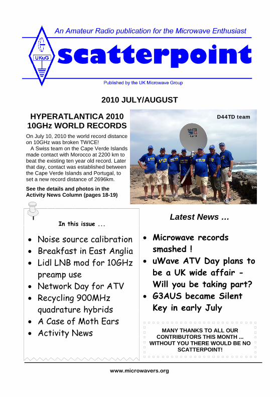
HYPERATLANTICA 2010 10GHz WORLD RECORDS
On July 10, 2010 the world record distance on 10GHz was broken TWICE! A Swiss team on the Cape Verde Islands made contact with Morocco at 2200 km to beat the existing ten year old record. Later that day, contact was established between the Cape Verde Islands and Portugal, to set a new record distance of 2696km.
See the details and photos in the Activity News Column (pages 18-19)
D44TD team
Hello once again.
The co-editors of this newsletter have been enjoying some fine French holiday weather over the past few weeks but now it’s time to get back to editing! Robin, G8APZ, is still in France but I had to reluctantly return from Brittany to catch up with domestic duties. I also recently gave my well known red VW Transporter microwave-shack-on-wheels to my youngest son for his ‘gigging’ commitments and am now running a smaller vehicle. It looks like my portable days could be over unless I downsize the radio gear and dishes … but I’ve never been a believer in small antennas and ‘flea power’! I’m now thinking ‘trailer’ …..
My grateful thanks to all our contributors this month. Just a few hours ago, I had 5 blank pages to fill and nothing to put in them and then Grant G8UBN’s article arrived by email … he’s a veritable angel of mercy!
This adds to the excellent article on 900MHz hybrids by John, G4BAO, who allowed me to pinch it from his excellent website http://www.g4bao.com . Finally, John M0ELS came up with a most useful and practical article on making a 10GHz preamp from a £2.50 Lidl satTV LNB. He also supplied another short article for next month. Thanks John! That said, we are still in dire need of more technical and other input from you, the readers. The September issue could be late in arriving as we only have material for less than 10 pages out of the normal 20. Get busy folks!
73 from Peter, G3PHO Editor
Page 2
News, views and articles for this newsletter are always welcome. Please send them to G3PHO (preferably by email) to the address shown above. The CLOSING date is the FIRST day of the month if you want your material to be published in the next issue.
UK Microwave Group Contact Information
From the Editor’s Desk
Scatterpoint 2010 JULY/AUGUST
Chairman: G4BAO Dr. John C. Worsnop Email: [email protected] Located: Cambridgeshire (JO02CG ) Address: 20 Lode Avenue, Waterbeach, Cambs, CB25 9PX Home Tel: ++44 (0)1223 862480
General Secretary: G8KMH Lehane Kellett Email: [email protected] Located: Hampshire (IO91) Address: Honey Cottage, Bent Street, Nether Wallop, Hants., SO20 8EJ Home Tel: ++44 (0)1264 781786
Membership Secretary: G8DKK Bryan Harber Email: [email protected] Located: Hertfordshire (IO91VX)
Address: 45 Brandles Road Letchworth Hertfordshire, SG6 2JA Home Tel: n/a
Treasurer: G4FSG Graham Murchie Email: [email protected] Located: Suffolk (JO02) Address: 42 Catherine Road, Woodbridge, Suffolk, IP12 4JP Home Tel: ++44 (0)7860 356775
Scatterpoint General Editor: G3PHO, Peter Day Email: [email protected] Located: South Yorkshire (IO93GJ) Address: 146 Springvale Road, Sheffield, S6 3NU, United Kingdom Home Tel: ++44 (0)114 2816701 (after 6pm)
Scatterpoint Activity News Editor: G8APZ Robin Lucas Email: scatterpoint @microwavers.org Located: Essex (JO01DO) Address: 84 Woodman Road Brentwood Essex, CM14 5AZ Home Tel: ++44 (0)1277 211126
Contest & Awards Manager: G3XDY John Quarmby Email: [email protected] Located: Suffolk (JO02OB) Address: 12 Chestnut Close, Rushmere St. Andrew, Ipswich, Suffolk, IP5 1ED Home Tel: ++44 (0)1473 717 830
RSGB Microwave Manager: G6JYB Murray Niman Email: [email protected] Located: Essex (JO01) Address: 55 Harrow Way Great Baddow Chelmsford Essex, CM2 7AU Home Tel: ++44 (0)1245 474969

Beacon PI7RTD/B 3cm From:<[email protected]> Date: 25 Jun 2010
Yesterday I placed PI7RTD/b at its location and made it active. Frequencies: 10368.258MHz 700 mW, omni antenna @ 105 mtr/asl Look at www.qrz.com for info and photos The old call of the beacon was PI7GHG, and now change to PI7RTD . RTD stands for the city of Rotterdam. Best 73 John PE1GHG
Page 3 Scatterpoint 2010 JULY/AUGUST
UK MICROWAVE GROUP SUBSCRIPTION INFORMATION
The following subscription rates now apply. Please make sure that you pay the stated amounts when you renew your subs next time. If the amount is not correct your subs will be allocated on a pro-rata basis and you could miss out on a newsletter or two! Your personal renewal date is shown at the foot of your address label if you receive Scatterpoint in paper format. If you are an email subscriber then you will have to make a quick check with the member-ship secretary if you have forgotten the renewal date. From now please try to renew in good time so that continuity of newsletter issues is maintained. Put a renewal date reminder somewhere prominent in your shack (the editor suggests having it tattooed on your forearm!). Please also note the payment methods and be meticulous with Paypal and cheque details.
Renewal of subscriptions requiring a paper copy of Scatterpoint are as follows:
Delivery to: UK £ US $ Eur € UK 14.00 - - Europe 18.00 36.00 26.00 Rest of World 24.00 48.00 36.00
Payment can be made by:
* Paypal to [email protected]
or * a cheque (drawn on a UK bank) payable to 'UK Microwave Group' and sent to the membership secretary (or as a last resort, by cash sent to the treasurer!)
The standard membership rate for 2010 is:
UK £6.00 US $12.00 Europe €10.00
This basic sum is for UKuG membership. For this you receive Scatterpoint for FREE by email. If you want a paper copy then the higher rates apply.
Items for Sale NP3.4-12 12V 3.4Ah Sealed Lead acid batteries for sale £5.00 each new condition P-P UK £3.80
NiMh 7.2V GP 2400mAh packs £5.00 each condition new P-P UK £2.50
Contact Kevin G3AAF for more details @ [email protected] Mobile 07831614640
FREE (YES FREE!) PCB SERVICE
Chris, GW4DGU writes ... It's not the 1 April today is it? I take no re-sponsibility but this appeared on the Kicad PCB software discussion group. Kicad is a very highly recommended Open Source cross-platform package.
Strictly speaking this is off-topic but, given that Kicad is used by hobbyists, a free PCB service is likely to be of interest: http://www.spiritcircuits.com/services/go-naked It sounds a lot better than dissolving copper very slowly in all the wrong places with with ferric chloride but it also sounds too good to be true? Anyone tried this service? What's the catch?
Lest anyone should be led astray by the 'naked' aspect of the offer, it refers to the lack of tinning and solder resist ... Vy 73 Chris GW4DGU
Scatterpoint Page 4 2010 JULY/AUGUST
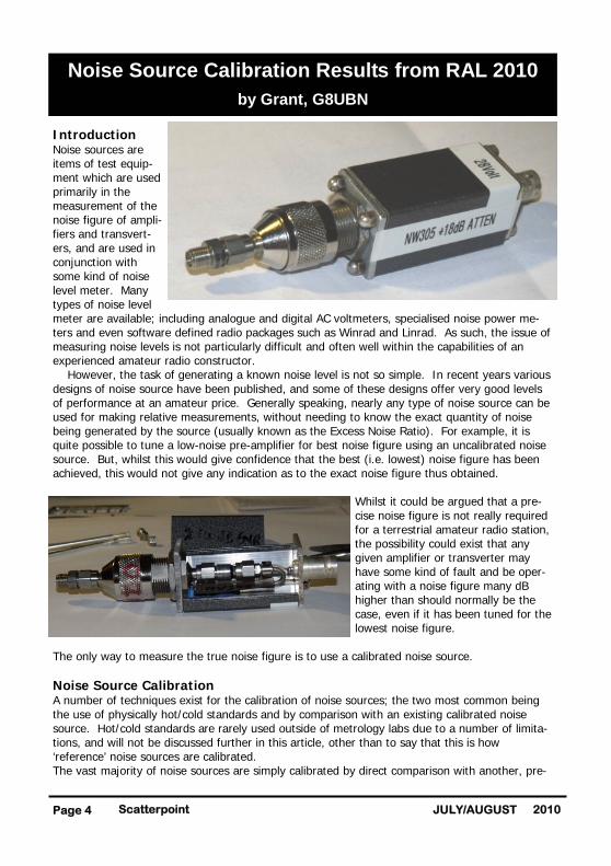
Introduction Noise sources are items of test equip-ment which are used primarily in the measurement of the noise figure of ampli-fiers and transvert-ers, and are used in conjunction with some kind of noise level meter. Many types of noise level meter are available; including analogue and digital AC voltmeters, specialised noise power me-ters and even software defined radio packages such as Winrad and Linrad. As such, the issue of measuring noise levels is not particularly difficult and often well within the capabilities of an experienced amateur radio constructor. However, the task of generating a known noise level is not so simple. In recent years various designs of noise source have been published, and some of these designs offer very good levels of performance at an amateur price. Generally speaking, nearly any type of noise source can be used for making relative measurements, without needing to know the exact quantity of noise being generated by the source (usually known as the Excess Noise Ratio). For example, it is quite possible to tune a low-noise pre-amplifier for best noise figure using an uncalibrated noise source. But, whilst this would give confidence that the best (i.e. lowest) noise figure has been achieved, this would not give any indication as to the exact noise figure thus obtained.
Whilst it could be argued that a pre-cise noise figure is not really required for a terrestrial amateur radio station, the possibility could exist that any given amplifier or transverter may have some kind of fault and be oper-ating with a noise figure many dB higher than should normally be the case, even if it has been tuned for the lowest noise figure.
The only way to measure the true noise figure is to use a calibrated noise source. Noise Source Calibration A number of techniques exist for the calibration of noise sources; the two most common being the use of physically hot/cold standards and by comparison with an existing calibrated noise source. Hot/cold standards are rarely used outside of metrology labs due to a number of limita-tions, and will not be discussed further in this article, other than to say that this is how ‘reference’ noise sources are calibrated. The vast majority of noise sources are simply calibrated by direct comparison with another, pre-
Noise Source Calibration Results from RAL 2010
by Grant, G8UBN
Page 5 Scatterpoint 2010 JULY/AUGUST
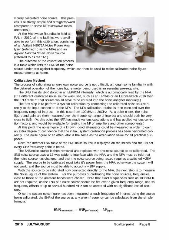
viously calibrated noise source. This proc-ess is relatively simple and straightforward (compared to some RF/microwave meas-urements!). At the Microwave Roundtable held at RAL in 2010, all the facilities were avail-able to perform this calibration, consisting of an Agilent N8975A Noise Figure Ana-lyser (referred to as the NFA) and an Agilent N4002A Smart Noise Source (referred to as the SNS). The outcome of the calibration process is a table which lists the ENR of the noise source under test against frequency, which can then be used to make calibrated noise figure measurements at home. Calibration Method The process of calibrating an unknown noise source is not difficult, although some familiarity with the detailed operation of the noise figure meter being used is an essential pre-requisite. The SNS has its ENR stored in an EEPROM internally, which is automatically read by the NFA. (If a different calibrated noise source was used, such as an HP 346 or an Eaton/Ailtech 7616 then the ENR table of that source would have to be entered into the noise analyser manually.) The first step is to perform a system calibration by connecting the calibrated noise source di-rectly to the input connector of the NFA. The NFA calibration routine is then executed over the frequency range of interest – in this case from 100MHz to 26GHz. As a quick check, the noise figure and gain are then measured over the frequency range of interest and should both be very close to 0dB. (At this point the NFA has made various calculations and has applied various correc-tion factors, and would be available for testing the NF of amplifiers and other components.) At this point the noise figure of a known, good attenuator could be measured in order to gain an extra degree of confidence that the initial, system calibration process has been performed cor-rectly. The noise figure of an attenuator is the same as the attenuation value for all practical pur-poses. Next, the internal ENR table of the SNS noise source is displayed on the screen and the ENR at every GHz frequency point is noted. The SNS noise source is then removed and replaced with the noise source to be calibrated. The SNS noise source uses a 12-way cable to interface with the NFA, and the NFA must be told that the noise source has changed, and that the noise source being tested requires a switched +28V supply. The source to be calibrated must take it’s power from the NFA, otherwise the system will not work, and the source must be able to accept a +28V supply. With the source to be calibrated now connected directly to the NFA, the next step is to measure the Noise Figure of the system. For the purposes of calibrating the noise sources, frequencies close to those of the amateur bands were chosen. Note that exact frequencies such as 10368MHz are not required, as the ENR of a noise source should be flat over a given frequency range, and so frequency offsets of up to several hundred MHz can be accepted with no significant loss of accu-racy. Once the system noise figure has been measured at each frequency of interest using the source being calibrated, the ENR of the source at any given frequency can be calculated from the simple formula: ENR(unknown) = ENR(reference) – NF(sys)
Scatterpoint Page 6 2010 JULY/AUGUST
Results First, the ENR of the SNS reference source :-
Next, the measured system noise figure with the two sources being tested :-
And finally, the ENR of the noise sources :-
Note that the ENR of the source supplied by G0NZO dropped off rapidly at frequencies above 10GHz,and so was not measured at 24GHz as this would likely not be a meaningful result. Notes i) The value of ENR is not a measure of ‘quality’ – bigger is definitely not better! In fact, for measuring very low noise figures (<10 dB or so) a noise source with a low ENR has a small advantage over one with a larger ENR, although this is not likely to be of any consequence for amateur radio applications – certainly ANY calibrated noise source is better than an uncalibrated one. ii) There is always an uncertainty with associated with any measurement, and this includes the ENR of the reference source which is typically in the range 0.15 – 0.2dB. In addition, there is the uncertainty of the system noise figure with the unknown source, which could be in the region of 0.2dB or so. Therefore, the uncertainty of the ENR of the source under test would be in the region of 0.3-0.4dB or so. iii) A professionally calibrated noise source would also state the SWR of the noise source, and how much that SWR changes when the source is both ‘on’ and ‘off’ – this is important when measuring ultra-low noise pre-amps which usually require an extremely low, and stable, SWR for best accuracy. Conclusion The process of calibrating an unknown noise source for amateur radio purposes is not particularly difficult, and has been described using the Agilent N8975A Noise Figure Analyser and N4002A SNS noise source. The same basic principles can be applied using the more commonly available HP8970 or Eaton 2075 noise figure meters with a suitable pre-calibrated noise source.
Frequency (MHz) 100 1000 2000 3000 5000 6000 10000 11000 24000
ENR (dB) 15.1 14.6 14.7 14.5 14.4 14.6 15.5 15.4 15.2
Frequency (MHz) 144 414 1269 2304 3428 5722 10354 18000 24078 NF(dB) G4BAO 11.3 10.9 10.3 10.4 11.2 11.5 12.6 11.4 14.7 G0NZO 4.6 5.3 4.5 5 6.2 9.2 6.6 12.8 -
Frequency (MHz) 144 414 1269 2304 3428 5722 10354 18000 24078 ENR(dB) G4BAO 3.78 4.03 4.33 4.24 3.28 3.04 2.86 3.89 0.50
G0NZO 10.48 9.63 10.13 9.64 8.28 5.34 8.86 2.49 -
Page 7 Scatterpoint 2010 JULY/AUGUST
References The majority of references on the subject of accurate noise figure measurements are aimed at professional engineers, and therefore contain a certain amount of mathematics. For those wish-ing to explore the subject further, the following references may be of use :- 1. Agilent Technologies Application Note AN57-1 Fundamentals of RF and Microwave Noise Figure Measurement: http://cp.literature.agilent.com/litweb/pdf/5952-8255E.pdf (This is THE definitive article on noise figure measurement and is an absolute must-read for any-body wishing to understand the subject in detail)
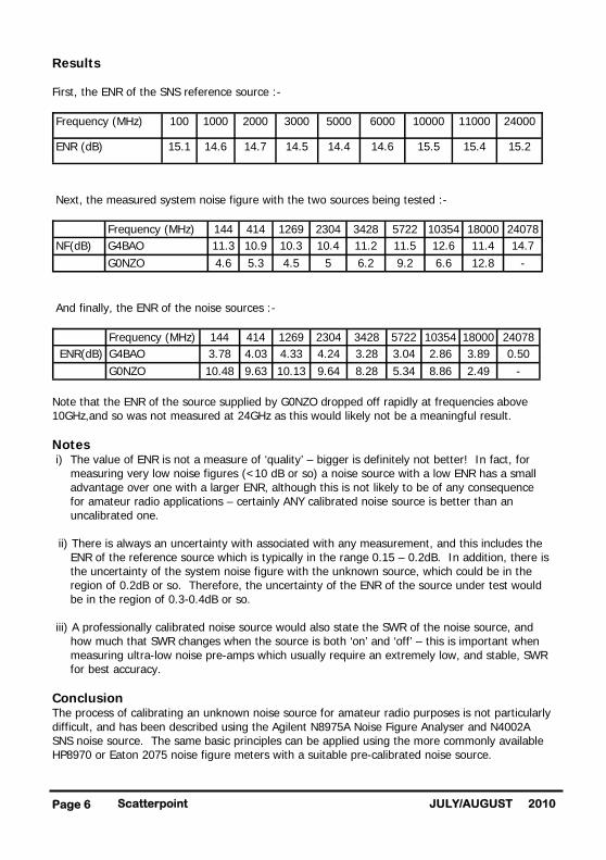
2. Agilent Technologies Application Note AN57-2 Noise Figure Measurement – the Y-factor method: http://cp.literature.agilent.com/litweb/pdf/5952-3706E.pdf (More maths, but another superb reference which gives even more details of the subject) Acknowledgements Thanks to Jules G0NZO and John G4BAO for providing the sources to be calibrated. The photos are courtesy of G0NZO and show the internal and external construction of his noise source.
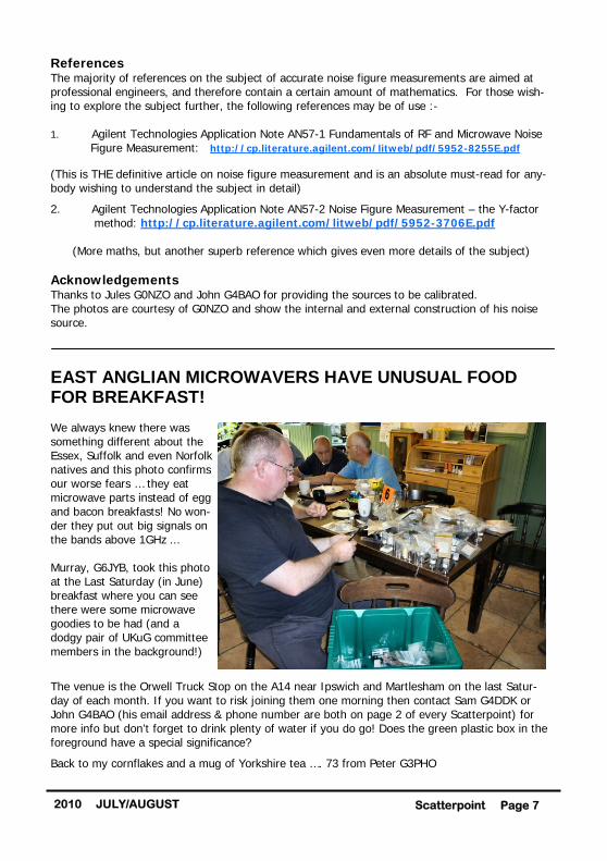
EAST ANGLIAN MICROWAVERS HAVE UNUSUAL FOOD FOR BREAKFAST! We always knew there was something different about the Essex, Suffolk and even Norfolk natives and this photo confirms our worse fears … they eat microwave parts instead of egg and bacon breakfasts! No won-der they put out big signals on the bands above 1GHz ... Murray, G6JYB, took this photo at the Last Saturday (in June) breakfast where you can see there were some microwave goodies to be had (and a dodgy pair of UKuG committee members in the background!)
The venue is the Orwell Truck Stop on the A14 near Ipswich and Martlesham on the last Satur-day of each month. If you want to risk joining them one morning then contact Sam G4DDK or John G4BAO (his email address & phone number are both on page 2 of every Scatterpoint) for more info but don’t forget to drink plenty of water if you do go! Does the green plastic box in the foreground have a special significance?
Back to my cornflakes and a mug of Yorkshire tea …. 73 from Peter G3PHO
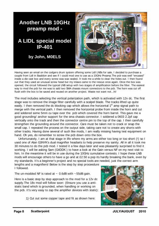
Having seen an email on the codgers drum system offering some Lidl LNBs for sale, I decided to purchase a couple from Lidl in Basildon and see if I could mod one to use as a 10GHz Preamp.The pcb was well “encased” inside a die cast box and every screw was wax sealed. It took me a while to clear the holes out. I then found out that they used an unusual screw head but my inlaws came to the rescue once again. Once the box was opened, the circuit followed the typical LNB setup with two stages of amplification before the filter. The easiest way to mod the pcb for me was to add two SMA chassis mount connectors to the pcb. The horn was cut off flush with the box to be saved and reused on another project. Waste not want not...hi! The mod includes selecting the vertical polarization path, which is activated with 12v dc. The first stage was to remove the image filter carefully with a scalpel blade. The tracks lifted up quite easily. I then removed the dc blocking cap which allows the horizontal 1st amp signal path to merge with the vertical path. I then removed the horizontal probe from inside the horn and cut and soldered some 5mm cu tape over the pcb which covered the horn barrel. This gave me a good grounding/ anchor support for the sma chassis connector. I soldered a 0603 2.2pf cap vertically onto the track and then the connector centre pin to the top of the cap. I then carefully strengthen the grounding around the connector. Care must be taken not to crack or snap the small cap. I repeated the process on the output side, taking care not to create any shorts with other tracks. Having done several of such like mods, I am really missing having test equipment on hand. Oh yes, do remember to screw the pcb down onto the box. Unfortunately, I am at that stage in life where my arms are either too long or too short (!) so I used one of Alan G3NYK’s dual magnifier headsets to help preserve my sanity. All in all it took me 30 minutes to do the pcb mod. I tested it a few days later and was pleasantly surprised to find it working. I will be asking Sam (G4DDK ) to have a look at the Gain versus NF on my next visit to him. In the meantime it will be in use during the 10GHz cumulative contests. I hope these LNB mods will encourage others to have a go and at £2.50 a pop its hardly breaking the bank, even by my standards. It’s a beginner’s project and no special tools are needed, just the correct arm lengths and a magnifiers! Below is the step by step proceedure I followed.
The un-modded NF is rated at ~ 0.6dB with ~55dB gain.
Here is a basic step by step approach to the mod for a 12v dc supply.The 18v mod will follow soon: (Ensure you use a anti-static band which is grounded, when handling or working on the pcb. It’s very easy to zap the amplifier devices with static):
1) Cut out some copper tape and fit as shown here:
Scatterpoint Page 8 2010 JULY/AUGUST
Another LNB 10GHz
preamp mod -
A LIDL special model IP-401
by John, M0ELS
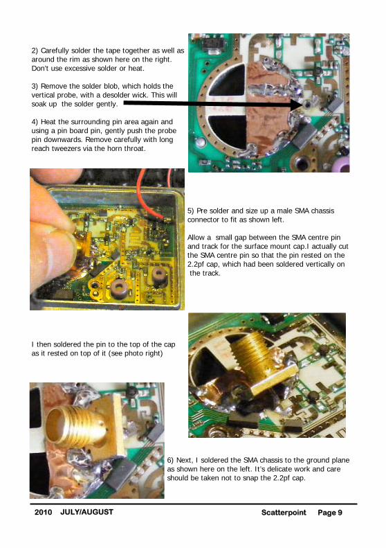
2) Carefully solder the tape together as well as around the rim as shown here on the right. Don’t use excessive solder or heat. 3) Remove the solder blob, which holds the vertical probe, with a desolder wick. This will soak up the solder gently. 4) Heat the surrounding pin area again and using a pin board pin, gently push the probe pin downwards. Remove carefully with long reach tweezers via the horn throat.
5) Pre solder and size up a male SMA chassis connector to fit as shown left. Allow a small gap between the SMA centre pin and track for the surface mount cap.I actually cut the SMA centre pin so that the pin rested on the 2.2pf cap, which had been soldered vertically on the track.
I then soldered the pin to the top of the cap as it rested on top of it (see photo right)
6) Next, I soldered the SMA chassis to the ground plane as shown here on the left. It’s delicate work and care should be taken not to snap the 2.2pf cap.
Page 9 Scatterpoint 2010 JULY/AUGUST

7) Remove the dc blocking cap 8) Remove the filter as shown below with a scalpel by lifting one end and peel the tracks off.
9) Solder a 2.2pf cap to the track as shown here, bearing in mind that the centre pin of the connector must rest on top of the cap. 10) Straddle the SMA connector across the two ground strips as shown and trim the centre pin as required, so that it rests on top of the 2.2pf cap. 11) Brace this connector well to prevent it from moving. 12) Solder the top of the cap to the connector centre pin as shown in the photo right. Well, that’s about it for the 12v mod version. As I said earlier, I don’t have any means to measure the LNB but, if someone could do the measurements, I would like to see the results posted here. It took me about 30 minutes to complete the mod excluding the taking of pics, resizing and doing this document. One final point … Remember to replace the screw which holds the pcb to the casting and the neck of the horn can also be cut off with a hacksaw and re-used. Unfortunately, the cover will not fit back on but one can always mount the SMA connectors onto the diecast cover and use a short length of cable to the pcb. Either way, its fun and a cheap way to make a 10GHz preamp. Enjoy!
73 from John - M0ELS
Scatterpoint Page 10 2010 JULY/AUGUST
Page 11 Scatterpoint 2010 JULY/AUGUST
It is proposed to hold a one day ATV event, to be called “Network Day”, to attract as many stations as possible to take part by creating a series of high power well sited stations at key locations. The key stations will, wherever possible, be capable of providing a link to a second key sta-tion or to a repeater input or to an individual home or portable station. The event will be held on August 22nd, , which is an existing microwave cumulative con-test/activity day, with a view to providing contactsf or ATV and narrowband microwave sta-tions.
1. Support is sought from groups interested in ATV and microwave activity who can provide a key station, on a high location, with as many bands as possible. 1. An effort will be made to interlink the key stations to act as relay stations. 2. If possible, a feed into a local repeater or directly in the BATC streamer would be an advantage to create the widest coverage. 3. Well-sighted locations to give maximum coverage. 4. Highest ERP consistent with the ability to act as a relay. 5. Upper microwave bands to used to provide opportunity for stations to use the bands for longer contacts. The same equipment could also function as “Key” station relay equipment. 7. G3PHO and G3PYB plan to activate a high site in the Pennines in the centre of England (Merryton Low). MODTS will be in the North on North Yorkshire Moors, G3SMU and G7LWT will be in the N.West on Winter Hill, G3KKD and the Cambridge group in the East, Grimsby Group on the Lincolnshire Wolds, G3ZME on Brown Clee in the Midlands. G8ADM North London. 8. High ERP stations on the most popular bands such as (FM) 23 and 3cm are sought but we would like to promote DATV as much as possible including 70cm. This should provide added incentive for stations to try new equipment for DATV and other bands such as 3.4 and 5.7GHz. With the high Power stations, it should be possible to work Dutch and French stations on 70cm and other bands. This is rare opportunity to have so many ATV FM and DATV active on one day. Key station locators: M0DTS IO94LJ G3PHO & G3PYB IO93AD G3ZME Group IO82QL G3SMU & G7LWT IO83RP G3KKD & Cambridge group G8ADM North London Station list, Symbol rates, FEC, etc are on the BATC Forum at www.batc.org.uk/forum/ and take a look at the chit chat DATV pages. Contact for skeds via BATC forum or [email protected]
Network day for ATV

Introduction During the development of my 23cm PA, I had in mind to combine the finished design in pairs to produce higher power. A very efficient way to do this is to split the power and feed each amplifier in quadrature (90 degrees out of phase) and recombine the outputs via a further quadrature coupler such that the output powers combine in phase. The most straightforward quadrature combiner can be made using a rectangle of microstrip lines consisting of parallel 50 and 36 ohm lines as per Figure 1 and operation is described in detail on the excellent “Microwaves101” website: http://www.microwaves101.com/encyclopedia/Branchline_couplers.cfm, from which Fig 1 is taken.
Figure 1: Quadrature hybrid combiner Reasonably priced 23cm hybrid PCBs can purchased from the US, or home made by etching them on PCB material but, for any sort of power, FR4 tends to be lossy and overheat. There are examples of hybrid designs by Charlie, G3WDG, in Backscatter. The PCBs then have to be mounted in a box with suitable connectors. The Bodger’s alternative Recently, there have been a number of beautifully made hybrids for the 900MHz band appearing at rallies and microwave round tables. They were manufactured by Aerial Facilities in the UK. AFL, as they were known, is now part of Axell Wireless http://www.axellwireless.com. No data for the couplers is available on their web site as far as I can see but, from measurement, these hybrids are centred on around 900MHz. They are in heavy duty beige-painted milled boxes with four N connectors and no other markings. They are worth the price for the box and connectors alone but, on opening them up, you find a hybrid printed on high quality, low-loss 1.6mm Teflonboard.
Scatterpoint Page 12 2010 JULY/AUGUST
Recycling Aerial Facilities 900MHz quadrature hybrids for 23cm
By John, G4BAO © 2009 Bravo Alpha Oscar
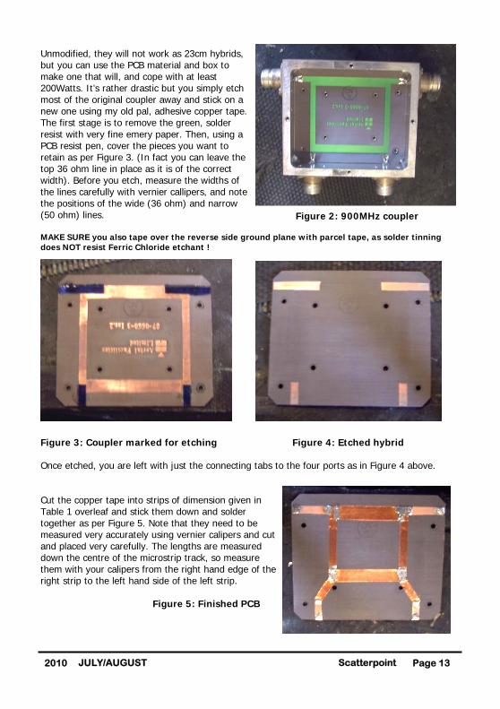
Unmodified, they will not work as 23cm hybrids, but you can use the PCB material and box to make one that will, and cope with at least 200Watts. It’s rather drastic but you simply etch most of the original coupler away and stick on a new one using my old pal, adhesive copper tape. The first stage is to remove the green, solder resist with very fine emery paper. Then, using a PCB resist pen, cover the pieces you want to retain as per Figure 3. (In fact you can leave the top 36 ohm line in place as it is of the correct width). Before you etch, measure the widths of the lines carefully with vernier callipers, and note the positions of the wide (36 ohm) and narrow (50 ohm) lines. MAKE SURE you also tape over the reverse side ground plane with parcel tape, as solder tinning does NOT resist Ferric Chloride etchant !
Figure 3: Coupler marked for etching Figure 4: Etched hybrid Once etched, you are left with just the connecting tabs to the four ports as in Figure 4 above. Cut the copper tape into strips of dimension given in Table 1 overleaf and stick them down and solder together as per Figure 5. Note that they need to be measured very accurately using vernier calipers and cut and placed very carefully. The lengths are measured down the centre of the microstrip track, so measure them with your calipers from the right hand edge of the right strip to the left hand side of the left strip. Figure 5: Finished PCB
Page 13 Scatterpoint 2010 JULY/AUGUST
Figure 2: 900MHz coupler
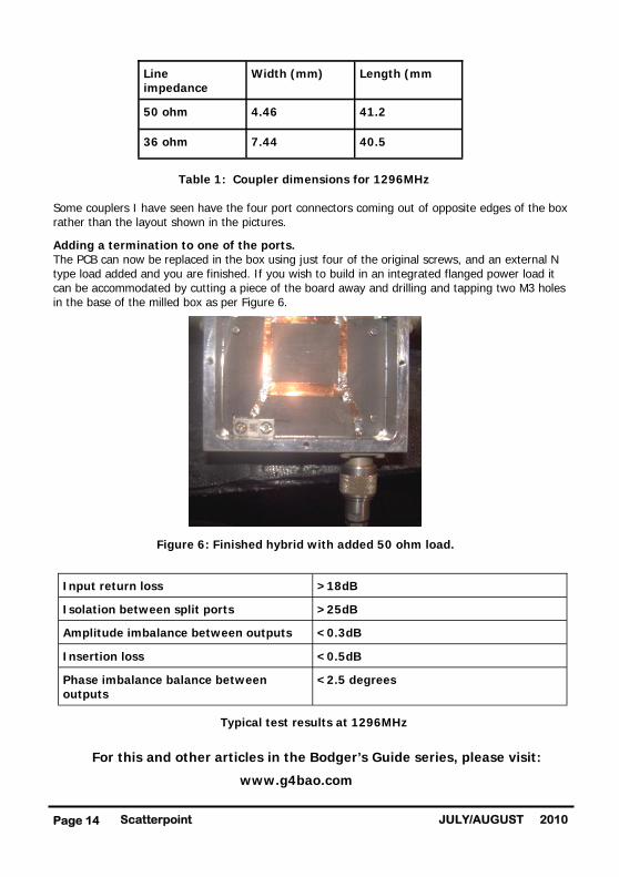
Table 1: Coupler dimensions for 1296MHz Some couplers I have seen have the four port connectors coming out of opposite edges of the box rather than the layout shown in the pictures.
Adding a termination to one of the ports. The PCB can now be replaced in the box using just four of the original screws, and an external N type load added and you are finished. If you wish to build in an integrated flanged power load it can be accommodated by cutting a piece of the board away and drilling and tapping two M3 holes in the base of the milled box as per Figure 6. Figure 6: Finished hybrid with added 50 ohm load.
Typical test results at 1296MHz
For this and other articles in the Bodger’s Guide series, please visit:
www.g4bao.com
Scatterpoint Page 14 2010 JULY/AUGUST
Line impedance
Width (mm) Length (mm
50 ohm 4.46 41.2
36 ohm 7.44 40.5
Input return loss >18dB
Isolation between split ports >25dB
Amplitude imbalance between outputs <0.3dB
Insertion loss <0.5dB
Phase imbalance balance between outputs
<2.5 degrees
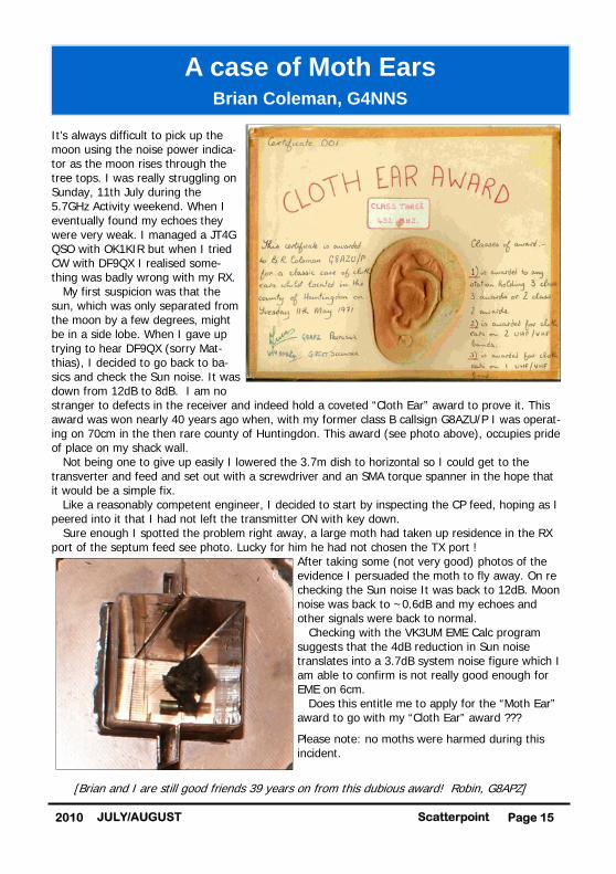
It’s always difficult to pick up the moon using the noise power indica-tor as the moon rises through the tree tops. I was really struggling on Sunday, 11th July during the 5.7GHz Activity weekend. When I eventually found my echoes they were very weak. I managed a JT4G QSO with OK1KIR but when I tried CW with DF9QX I realised some-thing was badly wrong with my RX. My first suspicion was that the sun, which was only separated from the moon by a few degrees, might be in a side lobe. When I gave up trying to hear DF9QX (sorry Mat-thias), I decided to go back to ba-sics and check the Sun noise. It was down from 12dB to 8dB. I am no stranger to defects in the receiver and indeed hold a coveted “Cloth Ear” award to prove it. This award was won nearly 40 years ago when, with my former class B callsign G8AZU/P I was operat-ing on 70cm in the then rare county of Huntingdon. This award (see photo above), occupies pride of place on my shack wall. Not being one to give up easily I lowered the 3.7m dish to horizontal so I could get to the transverter and feed and set out with a screwdriver and an SMA torque spanner in the hope that it would be a simple fix. Like a reasonably competent engineer, I decided to start by inspecting the CP feed, hoping as I peered into it that I had not left the transmitter ON with key down. Sure enough I spotted the problem right away, a large moth had taken up residence in the RX port of the septum feed see photo. Lucky for him he had not chosen the TX port !
After taking some (not very good) photos of the evidence I persuaded the moth to fly away. On re checking the Sun noise It was back to 12dB. Moon noise was back to ~0.6dB and my echoes and other signals were back to normal. Checking with the VK3UM EME Calc program suggests that the 4dB reduction in Sun noise translates into a 3.7dB system noise figure which I am able to confirm is not really good enough for EME on 6cm. Does this entitle me to apply for the “Moth Ear” award to go with my “Cloth Ear” award ???
Please note: no moths were harmed during this incident.
[Brian and I are still good friends 39 years on from this dubious award! Robin, G8APZ]
Page 15 Scatterpoint 2010 JULY/AUGUST
A case of Moth Ears
Brian Coleman, G4NNS

JUNE UK ACTIVITY CONTEST
From: Bob Price, G8DTF
A short report on activity here in IO83. There were at least a dozen Bolton Wire-less Club members active on 23cm for this event. I did not appear on 23cm as I had another band to play with - I went out portable with 13cm onto Winter Hill (IO83RO) where a number of other club members were active on 23cm. My equipment for 13cm is a trans-verter from Downeast Microwave plus a QBS267 SSPA (giving 10W output) along with a 16 element yagi. During the evening I managed contacts with MW1FGQ/p (IO83), G8ATB(IO83), G8JVM (IO82), G3VKV (IO81) and M0GHZ (IO81). The contacts with G3VKV and M0GHZ were difficult, but were eventually completed with a great deal of effort. I will have to look at ways of improving the system before next time, certainly a reasonable preamp and a better antenna.
73, Bob Price, G8DTF
JUNE LOW BANDS CONTEST
Ray, GM4CXM enjoyed this contest where the number of participants seemed to be up on previous events. Quite a few operators seemed to be spreading their activity by going off to do other things, and then coming back. Ray had a number of breaks, but his final tally of 26 contacts was in excess of past contact counts for this UKuG contest. The east coast appeared to benefit from improved conditions to the continent at the start, although this fell away later and in particular after the EU microwave Field Day activity finished in mid-afternoon. Ray noted that activity from some areas of the country was down in numbers in comparison with the UKAC contests - he noted three from GM, nothing from GW and only a couple of IO83s worked. On the positive side, some of the more "hard to find" squares like IO82 and IO93 had plenty of activity whilst a welcome
It’s summer and the contest calendar is in full swing. There is something for everyone, across all of the microwave bands. Remember the French activity too. Their talkback on 2m is 144.390MHz.
CONTEST and ACTIVITY REMINDER
August
17-Aug 1900 - 2130 1.3/2.3GHz Activity Contest Arranged by VHFCC (RSGB Contest) 22-Aug 0900 - 2000 4th 5.7GHz Cumulative 22-Aug 0900 - 2000 4th 10GHz Cumulative 22-Aug 0900 - 2000 4th 24GHz Cumulative
September
21-Sep 1900 - 2130 1.3/2.3GHz Activity Contest Arranged by VHFCC (RSGB Contest) 26-Sep 0900 - 2000 5th 5.7GHz Cumulative 26-Sep 0900 - 2000 5th 10GHz Cumulative 26-Sep 0900 - 2000 5th 24GHz Cumulative
October
2-Oct 1400 - 2200 1.3 & 2.3GHz Trophies Arranged by VHFCC (RSGB Contest) 2/3-Oct 1400 - 1400 432MHz & up Arranged by VHFCC (IARU/RSGB Contest) 3-Oct 0900 - 1700 3rd 24/47/76GHz Cumulative Aligned with IARU date
FRENCH JOURNEES d’ACTIVITE (JA)
28/29-Aug Activity weekend 25/26-Sep Activity weekend - 26th matches UKuG 30/31-Oct Activity weekend - 31st matches UKuG Duration of all JAs is 1700 Saturday - 1700 Sunday
By Robin Lucas, G8APZ
Scatterpoint Page 16 2010 JULY/AUGUST
addition to the log was Geoff GI0GDP at last. Ray says his only non-UK contact was with Kjeld OZ1FF - a station that he regularly works on aircraft scatter, and eleven of his contacts were over 400Km so conditions couldn’t have been too bad. Contacts came from the usual combination of listening, some via ON4KST, and lots of CQ calls. Talkback on 144.175MHz produced a few contacts, though many calls went unanswered.
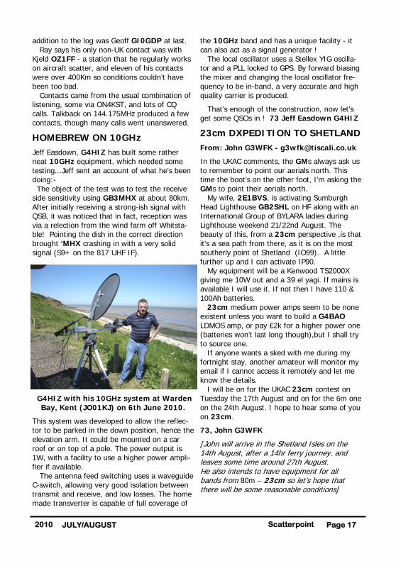
HOMEBREW ON 10GHz
Jeff Easdown, G4HIZ has built some rather neat 10GHz equipment, which needed some testing...Jeff sent an account of what he’s been doing:- The object of the test was to test the receive side sensitivity using GB3MHX at about 80km. After initially receiving a strong-ish signal with QSB, it was noticed that in fact, reception was via a relection from the wind farm off Whitsta-ble! Pointing the dish in the correct direction brought ‘MHX crashing in with a very solid signal (S9+ on the 817 UHF IF).
G4HIZ with his 10GHz system at Warden Bay, Kent (JO01KJ) on 6th June 2010.
This system was developed to allow the reflec-tor to be parked in the down position, hence the elevation arm. It could be mounted on a car roof or on top of a pole. The power output is 1W, with a facility to use a higher power ampli-fier if available. The antenna feed switching uses a waveguide C-switch, allowing very good isolation between transmit and receive, and low losses. The home made transverter is capable of full coverage of
the 10GHz band and has a unique facility - it can also act as a signal generator ! The local oscillator uses a Stellex YIG oscilla-tor and a PLL locked to GPS. By forward biasing the mixer and changing the local oscillator fre-quency to be in-band, a very accurate and high quality carrier is produced.
That’s enough of the construction, now let’s get some QSOs in ! 73 Jeff Easdown G4HIZ
23cm DXPEDITION TO SHETLAND
From: John G3WFK - [email protected]
In the UKAC comments, the GMs always ask us to remember to point our aerials north. This time the boot’s on the other foot, I’m asking the GMs to point their aerials north. My wife, 2E1BVS, is activating Sumburgh Head Lighthouse GB2SHL on HF along with an International Group of BYLARA ladies during Lighthouse weekend 21/22nd August. The beauty of this, from a 23cm perspective ,is that it’s a sea path from there, as it is on the most southerly point of Shetland (IO99). A little further up and I can activate IP90. My equipment will be a Kenwood TS2000X giving me 10W out and a 39 el yagi. If mains is available I will use it. If not then I have 110 & 100Ah batteries. 23cm medium power amps seem to be none existent unless you want to build a G4BAO LDMOS amp, or pay £2k for a higher power one (batteries won’t last long though),but I shall try to source one. If anyone wants a sked with me during my fortnight stay, another amateur will monitor my email if I cannot access it remotely and let me know the details. I will be on for the UKAC 23cm contest on Tuesday the 17th August and on for the 6m one on the 24th August. I hope to hear some of you on 23cm.
73, John G3WFK
[John will arrive in the Shetland Isles on the 14th August, after a 14hr ferry journey, and leaves some time around 27th August. He also intends to have equipment for all bands from 80m – 23cm so let’s hope that there will be some reasonable conditions]
Page 17 Scatterpoint 2010 JULY/AUGUST
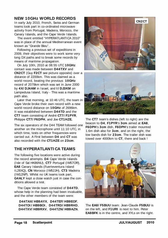
NEW 10GHz WORLD RECORDS In early July 2010, French, Swiss and German teams took part in co-ordinated microwave activity from Portugal, Madeira, Morocco, the Canary Islands, and the Cape Verde Islands. The event entitled “HYPERATLANTICA 2010” was in place of the annual Mediterranean event known as “Grande Bleu”. Following a previous set of expeditions in 2009, their objectives were to work some very long DX paths and to break some records by means of maritime propagation. On July 10th, 2010 at 08:55 UTC 10GHz contact was made between D44TXV and CN2CT (Guy F2CT see picture opposite) over a distance of 2200km. This was claimed as a world record, beating the previous 10GHz record of 2079km which was set in June 2000 by 4X/DJ4AM in Israel, and I/DJ3KM on Lampedusa Island, Italy - This was a maritime path also. Later that morning, at 10:46 UTC, the team in Cape Verde broke their own record with a new world record distance on 10GHz of 2696km. It was established between D44TD and the CT7 team consisting of André CT7/F1PYR, Philippe CT7/F6DPH, and Joe CT1HZE.
The six operators of the D44 TEAM followed one another on the microphone until 11:10 UTC, in which time, tests on other frequencies were carried out. A First between D4 and CT was also recorded with the CT1HZE on 23cm.
THE HYPERATLANTICA TEAMS
The following five locations were active during the record attempts. D4 Cape Verde Islands (Isle of Sal HK86NU), CT7 Portugal (IM57OR), EA8 Canary Islands (Fuerteventura Island IL28XQ), CN Morocco (IM52JH), CT3 Madeira (IM12NP). Whilst no UK teams took part, G4ALY kept a close watch just in case the con-ditions allowed a test.
The Cape Verde team consisted of D44TD, whose help in the planning had been invaluable, and the other members of the team were:
D44TAX/HB9AYX, D44TEF/HB9EOF, D44TOI/HB9BOI, D44TRD/HB9RHD, D44TXV/HB9RXV, D44TZN/HB9AZN.
The CT7 team’s dishes (left to right) are the beacon to D4, F1PYR’s 3cm aimed at EA8, F6DPH’s 3cm dish, F6DPH’s trailer mounted 1.6m dish also for 3cm, and on the right, the low bands dish for 23cm. The trailer dish was towed over 4000km to CT, there and back !
The EA8/F5BUU team: Jean-Claude F5BUU is on the left, and F1URI is next to him. Peter EA8BFK is in the centre, and XYLs on the right.
Scatterpoint Page 18 2010 JULY/AUGUST
CN2CT

In Madeira, CT3 (IM12NP), the team consisted of CT3/DG1GGH and CT3HF. They were happy to have a 10GHz first D4 to CT3 at a distance of 1852 km.
The map shows the paths covered on 10GHz by the various participating teams. The tests took place after over a year of preparations and a first attempt in 2009. The goal seemed almost impossible, to push forward the world record on 10GHz from 2079km to 2696 km. Congratulations to all of the teams. They all achieved the QSOs with D4. In preparing this piece, I have used number of sources. My thanks to Paul-Andre HB9RXV/D44TXV who provided the photos and the account of the D4
expedition. There will be more photos in next month’s issue.
DUCTING
Jim, GM3UAG is likely to have experienced maritime tropo ducting recently. Here is his interesting account of the experience:
On 22nd June 2010 at 16:25, I came home, switched on and copied GB3MHL on 23cm at S7, GB3MHS on 13cm at S6, PI7RTD on 13cm at S6, PI7ALK on 13cm at S7 and PI7QHN on 23cm at S4 - at long last, an opening! No other beacons or stations heard. On to ‘KST and, about 17:10, I fixed a sked with John, G3XDY on 23cm - nothing either way. Whilst I was calling ‘XDY, Ruud, PE1BTV broke in at S8 and gave me S5! Still no sign of ‘XDY! At about 17:30, I arranged a sked via ‘KST with OZ1FF, but that produced no copy either way. Those beacons were readable all evening at various signal strengths but no other stations were heard. The only thing more frustrating than the usual white noise here is hearing beacons at good strength but being unable to contact anybody! That brings back memories of 2m auroras many years ago! Presumably it’s to do with height above ground level? My beams are only about 6m above ground at 50m above sea level but I am on a south facing slope that stretches for about a mile down to the River Ythan. It runs into the North Sea at Newburgh, 20km N of Aberdeen and is tidal for about 1km upstream from my QTH. Still, 'patience is a virtue'!
73 Jim, GM3UAG
FRENCH ATV ACTIVITY
F6BGR and F6HXZ have announced the dates and locations in JO00 for Pascal F6HXZ to carry out ATV tests on 1200/1300MHz, 2300MHz and 10GHz, in analogue and digital modes.
The dates: August 9 to August 14, 2010. The place: Mainly the cliffs at Tréport (Dept 76) and Mers les Bains (Dept 80). Their holiday place is near sea level, so they will use the cliffs (100 m ASL). Activity will also be towards the UK if they can find any stations. For French stations, "G" stations who are QRV
Page 19 Scatterpoint 2010 JULY/AUGUST
Map by HB9BOI
on ATV are rare for direct QSOs. The talkback will be the usual ATV frequencies on 144.170, 144.160, 144.180 in SSB or FM [Aaarrrgghhh!] 5.7/10/24GHz CUMULATIVES
From: Martyn Vincent, G3UKV Sunday 27th June was the best session for some time. From Brown Clee, we had 19 QSOs on 3cm and 10 on 6cm, with only one QSO on each band attributable to 'KST (As a group, we far prefer 'Real Radio' talkback for microwave contests, and use a computer for the things it's best at). Best DX was Bart PA/ON4BV/p in JO11 on both bands SSB. We also made it both bands this time with G4ALY down in IO70. Several QSOs were 'tail-enders' - it's always worth checking one's own frequency before going back to CQ. We had 24GHz with us but, despite a couple of DX tests, no QSOs resulted. Roll on the 24/47/76 cumulative next month. 73 Martyn G3UKV (Telford &DARS group)
Bob, G8DTF reported a good level of activity too. He was only able to be out for three hours in the morning but still managed six QSOs, none of which were set-up on ‘KST. Three of these were from tail end calls, the others being set up via 144MHz talkback. Bob had two failed attempts. One with G8AIM who had heard him earlier on 10GHz and another with Ralph G4ALY. He suspects that the problem may have been a loose pointer on his compass rose because, when he checked the beacons just before packing up, it was about 10 degrees off, so this was probably the reason.
TROPO 23cm On 17th June, John, G3XDY worked SM7FWZ (JO77) 1046km, SM7GVF (JO77) 1019km, and SM6DVG (JO66). On 4th July, during VHF NFD, John also worked OK2KKW (JO60) and EB1RL/p (IN83) at a distance of 1055km.
TROPO 9cm/6cm On 20th July, G3XDY worked SM7ECM (JO65) on both 9cm and 6cm, at 877km.
TROPO 3cm On 5th June, G3XDY worked OZ2LD (JO54) at
755km, and on 16th June, Gordon, G0EWN worked Torben, OZ3ZW at 859kms.
RAINSCATTER John, G3XDY caught a few events on 3cm. On 6th June, DJ5BV (JO30), 3rd July DL7QY (JN59), DFØYY (JO62), DC6UW (JO44), and OK1VAM/p (JO60) at 838km. On 12th July, DJ5BV and DL7QY again, and on 14th July, DL3YEE (JO42) on 13cm, 6cm, and 3cm
BEACONS On 16th June, G0EWN heard the ON0GHZ beacon (JO20KV) on 3cm, at 519km. DB0GHZ was also received on a couple of occasions, and it was 599 on the evening of the 16th June.
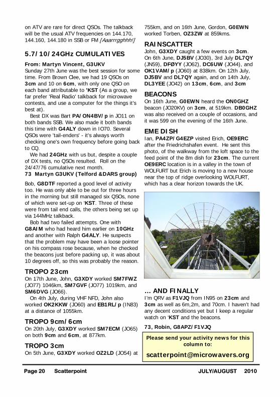
EME DISH Ian, PA4ZP/G4EZP visited Erich, OE9ERC after the Friedrichshafen event. He sent this photo, of the walkway from the loft space to the feed point of the 8m dish for 23cm. The current OE9ERC location is in a valley in the town of WOLFURT but Erich is moving to a new house near the top of ridge overlooking WOLFURT, which has a clear horizon towards the UK.
… AND FINALLY I’m QRV as F1VJQ from IN95 on 23cm and 3cm as well as 6m,2m, and 70cm. I haven’t had any decent conditions yet but I keep a regular watch on ‘KST and the beacons.
73, Robin, G8APZ/F1VJQ
Scatterpoint Page 20 2010 JULY/AUGUST
Please send your activity news for this column to: