Embed Size (px)
Citation preview
SSFL Stormwater Expert Panel∗
Robert Gearheart, Ph.D., P.E. Jonathan Jones, P.E., D.WRE Michael Josselyn, Ph.D. Robert Pitt, Ph.D., P.E., BCEE, D.WRE Michael K. Stenstrom, Ph.D., P.E., BCEE
Boeing Santa Susana Field Station 2010 Interim Source Removal Action (ISRA) Work Plan
Expert Panel Recommendations for Erosion Control Hydroseeding Methods
and Culvert Modification Areas for ISRA Excavation Areas in Outfall 009 Watersheds
July 21, 2010
Introduction This memorandum provides Expert Panel recommendations for sediment control and treatment associated with the 2010 ISRA Excavation Areas. Sediment transport is a primary concern in the discharge pollutants from the site. While excavation will reduce sources of pollutants at the identified ISRA sites, erosion from these areas may result in greater downstream sediment transport with any remaining associated pollutants. This report provides recommendations on improvements on hydromulching techniques, seed mixes, weed control, and use of culvert modifications where possible. Hydromulch Product Recommendations SSFL currently uses the product Flexterra-FGM. This product was recently refined and improved by the manufacturer. According to the manufacturer the new product, Flexterra High Performance – Flexible Growth Medium (Flexterra HP-FGM), has superior seed germination and growth rates than the original Flexterra-FGM. The manufacturer claims the germination rates are improved 600% and biomass is improved by 250% over the original product (See attached manufacture’s literature Appendix 1). Slight changes in the product recipe were made. The Materials Safety Data Sheet (MSDS) for the Flexterra HP-FGM are attached in Appendix 2. The only difference evident from the MSDS is the addition of guar gum. Guar gum is an edible carbohydrate polymer from a legume plant. It is a commonly added to hydromulch as a tackifier or thickener in foods and pharmaceuticals.
∗ The Expert Panel members are acting as private consultants in order to assist the Regional Board and The Boeing Company develop and implement methods to meet the requirements of Cease and Desist Order R4-2007-0056, dated November 1, 2007. Their opinions and directives are not the opinions and directives of their respective employers.
Hydromulch and Seed Installation Recommendations Typically, contractors apply hydroseed and mulch in one step because it is less expensive and broadly accepted in the industry. However, the manufacturer’s specifications for Flexterra-FGM and Flexterra HP-FGM, recommend applying hydroseed and mulch in a two-step application process. Seed suppliers (S&S Seed and Stover Seed) and the California Stormwater BMP Handbook also recommend a multi-step application process because it enhances seed to soil contact and offers better protection from predators. Seed germination rates should be improved with this process. The two-step process includes applying 50% of the seed and a small amount of flexible growth medium (FGM) for visual metering first. The second step is to mix the remaining seed and the rest of the FGM. We recommend that Boeing require the contractor to use the manufacturer recommended two-step application. This installation process is more costly but is proven to be more effective, especially for native seed applications. Long-term costs may be reduced with the increased effectiveness of erosion control and seed germination. Previously at SSFL, the contractor has applied the seed and mulch at the same time in one step (per Gabriella Castrellon of Dietz Hydroseeding). Seed Mix Recommendations 2010 ISRA work will be performed this summer creating new potential sources of erosion. Hydroseed applied this fall will have very little time to germinate and grow to provide adequate coverage – especially without irrigation. To make hydroseeding the most effective, a seed mix that will germinate rapidly is needed as is binding materials that would withstand any early precipitation events. The following table shows the original proposed seed mix and application rate as approved by CDFG (column 1). This mix was revised at some point according to the Boeing contractor, Dietz Hydroseeding (column 2) and has been applied at the site through 2009. While these species are all appropriate to the SSFL site the native shrubs tend to be slow growing and there has been limited coverage by grass species which can afford rapid colonization and sediment holding capability. In addition, the revised list removed two of the species of grass further reducing the capacity of the mix to provide fast vegetative cover. We recommend restoring the two grass species (Bromus arizonicus, and Nasella pulchra) to the mix. We also recommend adding small fescue (Vulpia microstachys) at a rate of 10 lbs/acre to provide quick vegetative cover for the first rainy season. Small fescue is not long-lived but it will provide temporary erosion control while the other native species gain biomass and provide long-term coverage. We also recommend increasing the application rate for some species to improve the chances of seed soil contact. See Column 3 for the recommended seed mix and application rate.
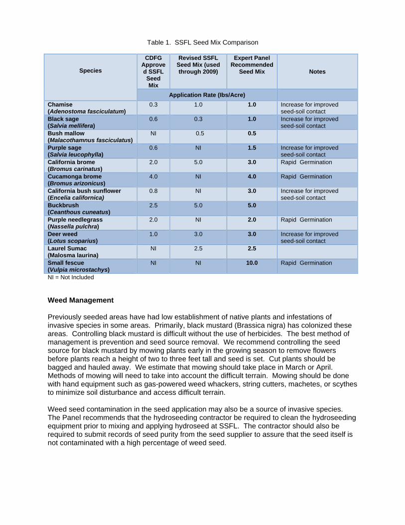
Table 1. SSFL Seed Mix Comparison
Species
CDFG Approved SSFL Seed Mix
Revised SSFL Seed Mix (used through 2009)
Expert Panel Recommended
Seed Mix Notes
Application Rate (Ibs/Acre)
Chamise (Adenostoma fasciculatum)
0.3 1.0 1.0 Increase for improved seed-soil contact
Black sage (Salvia mellifera)
0.6 0.3 1.0 Increase for improved seed-soil contact
Bush mallow (Malacothamnus fasciculatus)
NI 0.5 0.5
Purple sage (Salvia leucophylla)
0.6 NI 1.5 Increase for improved seed-soil contact
California brome (Bromus carinatus)
2.0 5.0 3.0 Rapid Germination
Cucamonga brome (Bromus arizonicus)
4.0 NI 4.0 Rapid Germination
California bush sunflower (Encelia californica)
0.8 NI 3.0 Increase for improved seed-soil contact
Buckbrush (Ceanthous cuneatus)
2.5 5.0 5.0
Purple needlegrass (Nassella pulchra)
2.0 NI 2.0 Rapid Germination
Deer weed (Lotus scoparius)
1.0 3.0 3.0 Increase for improved seed-soil contact
Laurel Sumac (Malosma laurina)
NI 2.5 2.5
Small fescue (Vulpia microstachys)
NI NI 10.0 Rapid Germination
NI = Not Included
Weed Management Previously seeded areas have had low establishment of native plants and infestations of invasive species in some areas. Primarily, black mustard (Brassica nigra) has colonized these areas. Controlling black mustard is difficult without the use of herbicides. The best method of management is prevention and seed source removal. We recommend controlling the seed source for black mustard by mowing plants early in the growing season to remove flowers before plants reach a height of two to three feet tall and seed is set. Cut plants should be bagged and hauled away. We estimate that mowing should take place in March or April. Methods of mowing will need to take into account the difficult terrain. Mowing should be done with hand equipment such as gas-powered weed whackers, string cutters, machetes, or scythes to minimize soil disturbance and access difficult terrain. Weed seed contamination in the seed application may also be a source of invasive species. The Panel recommends that the hydroseeding contractor be required to clean the hydroseeding equipment prior to mixing and applying hydroseed at SSFL. The contractor should also be required to submit records of seed purity from the seed supplier to assure that the seed itself is not contaminated with a high percentage of weed seed.

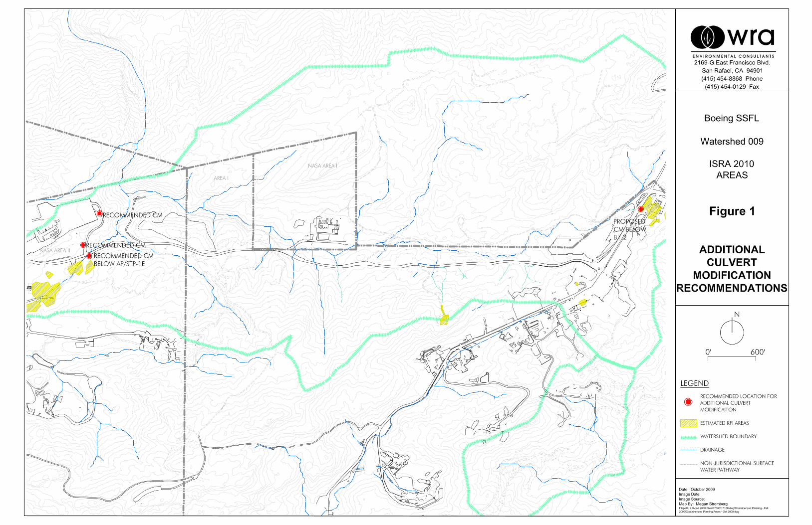
Because we can not predict all the weeds that may become established in the ISRA areas, we recommend that the areas are inspected in February. Species specific weed management strategies should be developed for implementation in March-April. Installation of additional culvert modification areas and maintenance of existing areas The Panel has reviewed the performance results of the culvert modification areas and believes that while the data is not consistent, these areas help to retain sediment and likely have a role in reducing pollutant discharges from open space areas. Therefore, pending further analysis as part of the Work Plan required by the Regional Water Quality Control Board, the Panel recommends the installation of additional culvert modification structures where possible. We understand that Boeing will be considering the installation of a culvert modification design on the drainage near the guard structure below RFI B1-2. The Panel supports the siting of an additional culvert modification structure at this location. The Panel has also identified three other locations where culvert modification structures could be beneficial because of their locations below RFI or paved areas (Figure 1). Previously installed culvert modification designs were based on hydraulic calculations to demonstrate percent of long-term capture, filtration capacity, or design flow rate, and water elevation during flood events to avoid problems with flooding. The Panel recommends a similar investigation is undertaken to ensure proper design of additional culvert modifications.

Appendix 1 Flexterra HP – FGM

Revolutionary Micro-Pore particles optimize water and nutrient retention
100% recycled Thermally Refined® wood fibers not only produce the highest yield and coverage per pound, they are also phyto-sanitized, eliminating weed seeds and pathogens
100% biodegradable interlocking man-made fibers help increase wet bond strength
100% non-toxic biopolymers and water absorbents further enhance performance
600% GReATeR GeRminATion, neARly peRfecT eRosion conTRol, now 100% biodeGRAdAble.
New patent-pending Flexterra® High Performance-Flexible Growth Medium™
(HP-FGM™) takes the near-perfect performance of the original Flexterra FGM
to an even higher level. Introduced in 2004, Flexterra FGM rapidly set a new
standard of excellence for controlling erosion and establishing vegetation on
severe slopes. It outperformed blankets and led the movement toward more
cost-effective, environmentally responsible hydraulically applied techniques.
Flexterra HP-FGM represents the next generation in Flexible Growth Media
and is proven to surpass the original’s outstanding performance.
New Flexterra HP-FGM delivers:
• The highest germination and growth establishment
• Greater than 99% erosion control effectiveness immediately upon application
• 100% biodegradability
• Greater safety for even the most sensitive aquatic environment because it’s non-toxic
• Near-perfect erosion control and denser vegetation while protecting the natural environment
New HP tecHNoloGy: GreeNer By desiGN
A008-17928_Flexterra_HP_sell_sh.indd 1 5/21/10 2:06:28 PM
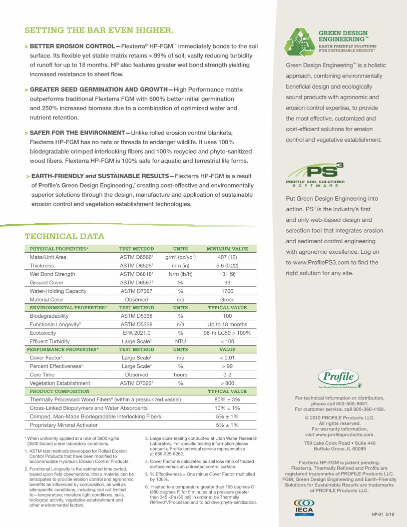
pHysicAl pRopeRTies* TesT meTHod UniTs minimUm VAlUe
Mass/Unit Area ASTM D65661 g/m2 (oz/yd2) 407 (12)
Thickness ASTM D65251 mm (in) 5.6 (0.22)
Wet Bond Strength ASTM D68181 N/m (lb/ft) 131 (9)
Ground Cover ASTM D65671 % 99
Water-Holding Capacity ASTM D7367 % 1700
Material Color Observed n/a Green
enViRonmenTAl pRopeRTies* TesT meTHod UniTs TypicAl VAlUe
Biodegradability ASTM D5338 % 100
Functional Longevity2 ASTM D5338 n/a Up to 18 months
Ecotoxicity EPA 2021.0 % 96-hr LC50 > 100%
Effluent Turbidity Large Scale3 NTU < 100
peRfoRmAnce pRopeRTies* TesT meTHod UniTs VAlUe
Cover Factor4 Large Scale3 n/a < 0.01
Percent Effectiveness5 Large Scale3 % > 99
Cure Time Observed hours 0-2
Vegetation Establishment ASTM D73221 % > 800
pRodUcT composiTion TypicAl VAlUe
Thermally Processed Wood Fibers6 (within a pressurized vessel) 80% ± 3%
Cross-Linked Biopolymers and Water Absorbents 10% ± 1%
Crimped, Man-Made Biodegradable Interlocking Fibers 5% ± 1%
Proprietary Mineral Activator 5% ± 1%
Green Design Engineering™ is a holistic
approach, combining environmentally
beneficial design and ecologically
sound products with agronomic and
erosion control expertise, to provide
the most effective, customized and
cost-efficient solutions for erosion
control and vegetative establishment.
Put Green Design Engineering into
action. PS3 is the industry’s first
and only web-based design and
selection tool that integrates erosion
and sediment control engineering
with agronomic excellence. Log on
to www.ProfilePS3.com to find the
right solution for any site.
* When uniformly applied at a rate of 3900 kg/ha (3500 lbs/ac) under laboratory conditions.
1. ASTM test methods developed for Rolled Erosion Control Products that have been modified to accommodate Hydraulic Erosion Control Products.
2. Functional Longevity is the estimated time period, based upon field observations, that a material can be anticipated to provide erosion control and agronomic benefits as influenced by composition, as well as site-specific conditions, including; but not limited to—temperature, moisture light conditions, soils, biological activity, vegetative establishment and other environmental factors.
3. Large scale testing conducted at Utah Water Research Laboratory. For specific testing information please contact a Profile technical service representative at 866-325-6262.
4. Cover Factor is calculated as soil loss ratio of treated surface versus an untreated control surface.
5. % Effectiveness = One minus Cover Factor multiplied by 100%.
6. Heated to a temperature greater than 193 degrees C (380 degrees F) for 5 minutes at a pressure greater than 345 kPa (50 psi) in order to be Thermally Refined®/Processed and to achieve phyto-sanitization.
HP-01 5/10
seTTinG THe bAR eVen HiGHeR.
> Better erosioN coNtrol—Flexterra® HP-FGM™ immediately bonds to the soil
surface. Its flexible yet stable matrix retains > 99% of soil, vastly reducing turbidity
of runoff for up to 18 months. HP also features greater wet bond strength yielding
increased resistance to sheet flow.
> Greater seed GerMiNatioN aNd GrowtH—High Performance matrix
outperforms traditional Flexterra FGM with 600% better initial germination
and 250% increased biomass due to a combination of optimized water and
nutrient retention.
> saFer For tHe eNviroNMeNt—Unlike rolled erosion control blankets,
Flexterra HP-FGM has no nets or threads to endanger wildlife. It uses 100%
biodegradable crimped interlocking fibers and 100% recycled and phyto-sanitized
wood fibers. Flexterra HP-FGM is 100% safe for aquatic and terrestrial life forms.
> eartH-FrieNdly and sustaiNaBle results—Flexterra HP-FGM is a result
of Profile’s Green Design Engineering™, creating cost-effective and environmentally
superior solutions through the design, manufacture and application of sustainable
erosion control and vegetation establishment technologies.
TecHnicAl dATA
GREEN DESIGN ENGINEERING™
EARTH-FRIENDLY SOLUTIONSFOR SUSTAINABLE RESULTS™
Flexterra HP-FGM is patent pending. Flexterra, Thermally Refined and Profile are
registered trademarks of PROFILE Products LLC. FGM, Green Design Engineering and Earth-Friendly
Solutions for Sustainable Results are trademarks of PROFILE Products LLC.
For technical information or distribution, please call 800-508-8681.
For customer service, call 800-366-1180.
© 2010 PROFILE Products LLC. All rights reserved.
For warranty information, visit www.profileproducts.com.
750 Lake Cook Road • Suite 440 Buffalo Grove, IL 60089
A008-17928_Flexterra_HP_sell_sh.indd 2 5/21/10 2:06:29 PM

Appendix 2 Materials Safety Data Sheet for Flexterra HP – FGM
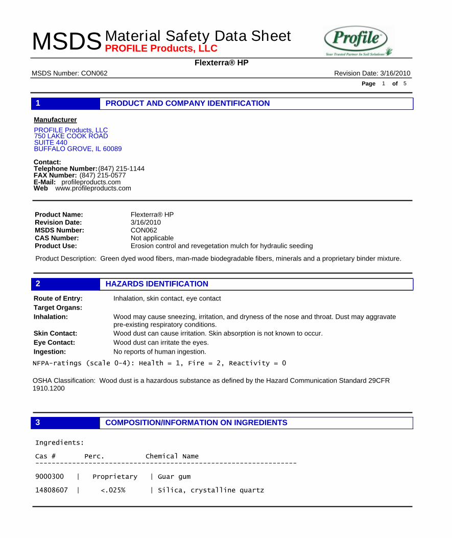
PRODUCT AND COMPANY IDENTIFICATION1ManufacturerPROFILE Products, LLC750 LAKE COOK ROADSUITE 440BUFFALO GROVE, IL 60089Contact:Telephone Number:FAX Number:E-Mail:Web
(847) 215-1144(847) 215-0577profileproducts.comwww.profileproducts.com
Product Description: Green dyed wood fibers, man-made biodegradable fibers, minerals and a proprietary binder mixture.
Flexterra® HP3/16/2010CON062Not applicableErosion control and revegetation mulch for hydraulic seeding
Product Name:Revision Date:MSDS Number:CAS Number:Product Use:
HAZARDS IDENTIFICATION2Inhalation, skin contact, eye contactRoute of Entry:
Target Organs:Wood may cause sneezing, irritation, and dryness of the nose and throat. Dust may aggravatepre-existing respiratory conditions.
Inhalation:Wood dust can cause irritation. Skin absorption is not known to occur.Skin Contact:Wood dust can irritate the eyes.Eye Contact:No reports of human ingestion.Ingestion:
OSHA Classification: Wood dust is a hazardous substance as defined by the Hazard Communication Standard 29CFR 1910.1200
NFPA-ratings (scale 0-4): Health = 1, Fire = 2, Reactivity = 0
COMPOSITION/INFORMATION ON INGREDIENTS3Ingredients: Cas # Perc. Chemical Name ---------------------------------------------------------------- 9000300 | Proprietary | Guar gum 14808607 | <.025% | Silica, crystalline quartz
Flexterra® HP
Material Safety Data Sheet Revision Date: 3/16/2010MSDS Number: CON062
Page of1 5
MSDS PROFILE Products, LLC
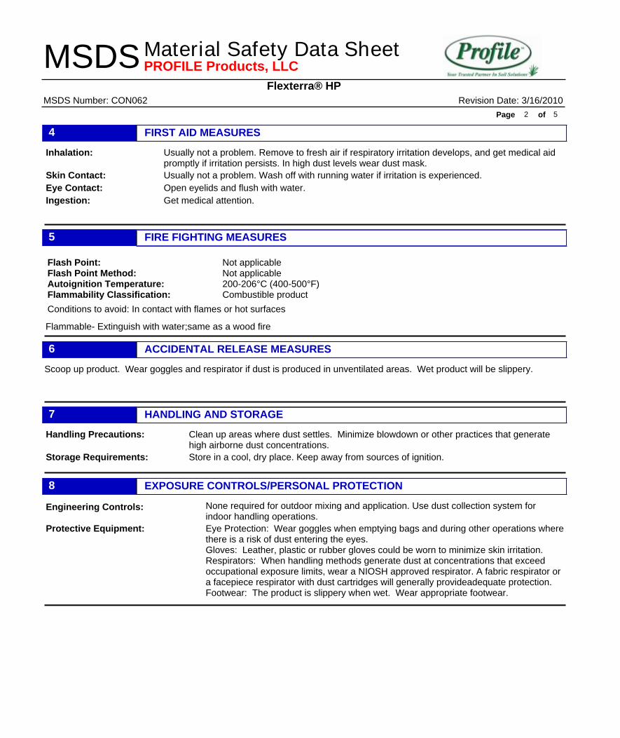
FIRST AID MEASURES4Usually not a problem. Remove to fresh air if respiratory irritation develops, and get medical aidpromptly if irritation persists. In high dust levels wear dust mask.
Inhalation:Usually not a problem. Wash off with running water if irritation is experienced.Skin Contact:Open eyelids and flush with water.Eye Contact:Get medical attention.Ingestion:
FIRE FIGHTING MEASURES5
Flammable- Extinguish with water;same as a wood fire Conditions to avoid: In contact with flames or hot surfaces
Flash Point:Flash Point Method:Autoignition Temperature:Flammability Classification:
Not applicableNot applicable200-206°C (400-500°F)Combustible product
ACCIDENTAL RELEASE MEASURES6Scoop up product. Wear goggles and respirator if dust is produced in unventilated areas. Wet product will be slippery.
HANDLING AND STORAGE7Clean up areas where dust settles. Minimize blowdown or other practices that generatehigh airborne dust concentrations.
Handling Precautions:Store in a cool, dry place. Keep away from sources of ignition.Storage Requirements:
EXPOSURE CONTROLS/PERSONAL PROTECTION8None required for outdoor mixing and application. Use dust collection system forindoor handling operations.
Engineering Controls:Eye Protection: Wear goggles when emptying bags and during other operations wherethere is a risk of dust entering the eyes.Gloves: Leather, plastic or rubber gloves could be worn to minimize skin irritation.Respirators: When handling methods generate dust at concentrations that exceedoccupational exposure limits, wear a NIOSH approved respirator. A fabric respirator ora facepiece respirator with dust cartridges will generally provideadequate protection.Footwear: The product is slippery when wet. Wear appropriate footwear.
Protective Equipment:
Flexterra® HP
Material Safety Data Sheet Revision Date: 3/16/2010MSDS Number: CON062
Page of2 5
MSDS PROFILE Products, LLC
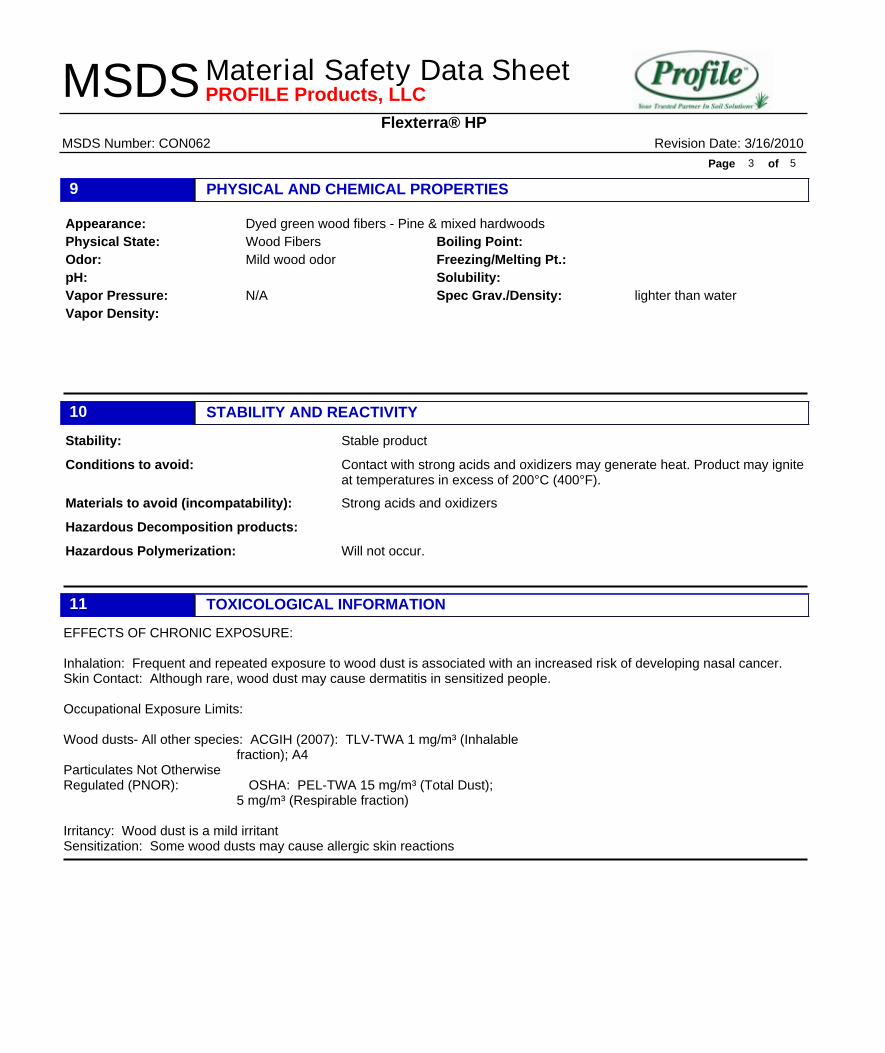
PHYSICAL AND CHEMICAL PROPERTIES9Dyed green wood fibers - Pine & mixed hardwoodsAppearance:Wood FibersPhysical State:Mild wood odorOdor:
pH:N/AVapor Pressure:
Vapor Density:
Boiling Point:Freezing/Melting Pt.:Solubility:
lighter than waterSpec Grav./Density:
STABILITY AND REACTIVITY10Stable productStability:Contact with strong acids and oxidizers may generate heat. Product may igniteat temperatures in excess of 200°C (400°F).
Conditions to avoid:
Strong acids and oxidizersMaterials to avoid (incompatability):Hazardous Decomposition products:
Will not occur.Hazardous Polymerization:
TOXICOLOGICAL INFORMATION11EFFECTS OF CHRONIC EXPOSURE: Inhalation: Frequent and repeated exposure to wood dust is associated with an increased risk of developing nasal cancer. Skin Contact: Although rare, wood dust may cause dermatitis in sensitized people. Occupational Exposure Limits: Wood dusts- All other species: ACGIH (2007): TLV-TWA 1 mg/m³ (Inhalable fraction); A4 Particulates Not Otherwise Regulated (PNOR): OSHA: PEL-TWA 15 mg/m³ (Total Dust); 5 mg/m³ (Respirable fraction) Irritancy: Wood dust is a mild irritant Sensitization: Some wood dusts may cause allergic skin reactions
Flexterra® HP
Material Safety Data Sheet Revision Date: 3/16/2010MSDS Number: CON062
Page of3 5
MSDS PROFILE Products, LLC
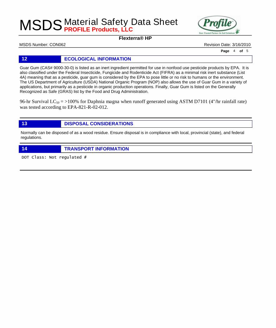
ECOLOGICAL INFORMATION12Guar Gum (CAS# 9000-30-0) is listed as an inert ingredient permitted for use in nonfood use pesticide products by EPA. It is also classified under the Federal Insecticide, Fungicide and Rodenticide Act (FIFRA) as a minimal risk inert substance (List 4A) meaning that as a pesticide, guar gum is considered by the EPA to pose little or no risk to humans or the environment. The US Department of Agriculture (USDA) National Organic Program (NOP) also allows the use of Guar Gum in a variety of applications, but primarily as a pesticide in organic production operations. Finally, Guar Gum is listed on the Generally Recognized as Safe (GRAS) list by the Food and Drug Administration. 96-hr Survival LC50 = >100% for Daphnia magna when runoff generated using ASTM D7101 (4"/hr rainfall rate) was tested according to EPA-821-R-02-012.
DISPOSAL CONSIDERATIONS13Normally can be disposed of as a wood residue. Ensure disposal is in compliance with local, provincial (state), and federalregulations.
TRANSPORT INFORMATION14DOT Class: Not regulated #
Flexterra® HP
Material Safety Data Sheet Revision Date: 3/16/2010MSDS Number: CON062
Page of4 5
MSDS PROFILE Products, LLC
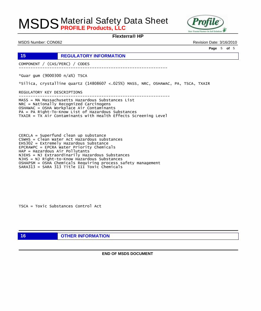
REGULATORY INFORMATION15COMPONENT / (CAS/PERC) / CODES --------------------------------------------------------------- *Guar gum (9000300 n/a%) TSCA *Silica, crystalline quartz (14808607 <.025%) MASS, NRC, OSHAWAC, PA, TSCA, TXAIR REGULATORY KEY DESCRIPTIONS ---------------------------------------------------------------- MASS = MA Massachusetts Hazardous Substances List NRC = Nationally Recognized Carcinogens OSHAWAC = OSHA Workplace Air Contaminants PA = PA Right-To-Know List of Hazardous Substances TXAIR = TX Air Contaminants with Health Effects Screening Level
CERCLA = Superfund clean up substance CSWHS = Clean Water Act Hazardous substances EHS302 = Extremely Hazardous Substance EPCRAWPC = EPCRA Water Priority Chemicals HAP = Hazardous Air Pollutants NJEHS = NJ Extraordinarily Hazardous Substances NJHS = NJ Right-to-Know Hazardous Substances OSHAPSM = OSHA Chemicals Requiring process safety management SARA313 = SARA 313 Title III Toxic Chemicals
TSCA = Toxic Substances Control Act
OTHER INFORMATION16
END OF MSDS DOCUMENT
Flexterra® HP
Material Safety Data Sheet Revision Date: 3/16/2010MSDS Number: CON062
Page of5 5
MSDS PROFILE Products, LLC
1
TECHNICAL MEMORANDUM: Recommended Procedures for Road Closures in the Outfall 008 and Outfall 009
Watersheds
Prepared by:
Surface Water Expert Panel Attn: Michael Josselyn, PhD
November 2, 2010
Introduction The Expert Panel has been participating in the review of the progress being made by Boeing on erosion control practices within the watersheds of Outfalls 008 and 009. Because soil erosion is an important factor in transport of pollutants off the property, the Panel has taken particular interest in measures to control soil loss from existing unpaved roads. Unpaved roads can also concentrate surface water runoff and increase water flow in areas that contribute to additional downslope erosion. Therefore, the Panel recommends that Boeing consider abandoning and restoring unpaved roads where use is no longer required. This memo sets forth the recommendations on specifications for the closure of unpaved roads. Site specific designs are not provided as the work often requires case-by-case evaluation. Instead, a set of guidelines and techniques for decommissioning, stabilizing, and re-vegetating the roads is provided below based on standards and experience developed by the US Forest Service and other open space agencies that have published standards on road decommissioning. Boeing is advised to assure that all actions undertaken in reliance on these recommendations is consistent with their federal and state water quality permits and the land development requirements for the County of Ventura and furthermore, is reviewed and approved by all associated land owners. Lastly, these guidelines do not provide an adequate level of detail for the closure of all roads. Boeing is advised to seek a geotechnical assessment where steep roads, embankments, or unstable soils are present. Goal The goal of road closure is to perform decompaction, temporary erosion control, and revegetate for long-term soil stability so that little or no maintenance is required so that little or no maintenance for erosion control is required in the future. Timing All road closure work should be performed during the dry season of any year or if not during this time, work should be phased such that erosion control measures are in place as closure work proceeds and that weather conditions are monitored such that any bare ground is properly managed to avoid erosion problems. When rain is predicted within the next five days, erosion control protections should be put in place. Hydroseed should be applied soon after ground disturbing work is completed. The ideal time to apply seed is 1 to 14 days before a light rain. Between October 30 and May 1,
2
weather should be monitored closely to ensure there is adequate time to apply hydroseed and other BMPs prior to rainfall. Equipment Heavy equipment used for road decommissioning typically includes a bulldozer with hydraulic rippers for de-compacting rocked roads and a hydroseeding truck to apply seed and mulch. A hydraulic excavator and dump truck may also be necessary to move soils from unstable areas to stable storage sites. Treatment of Unstable Areas Any unstable or potentially unstable road or landing fills should be excavated and stabilized so material does not fail and enter a watercourse or destroy down-slope vegetation. These sites are most likely to occur where roads have been cut into steep slopes or fill ‘dips’ on the hillside. One such area is shown in Figure 1. Management of Road Surface Runoff and other Drainage Roads that are to be closed and unmaintained should have adequate, self-maintaining surface drainage so that the road surface is stable and will not erode and deliver sediment to creeks. The following recommendations build upon road erosion control recommendations that were provided in the following documents: “Boeing SSFL Conceptual BMP Designs for Outfalls 008 and 009” (Geosyntec 2007), “Technical Memorandum: Cellular Confinement System Products for the Santa Susana Field Laboratory” (Geosyntec 2007), and “Stormwater Maintenance Activities” (Geosyntec 2008). Berms: Any berms at the outer edges of a road should be removed to encourage
drainage off the road surface. Out-slope closed roads whenever possible. Existing Ditches: Inside road ditches should be eliminated when closing roads so
that water is not diverted and gullies do not form. Any ditched segments of roads to be closed should be re-graded to be out-sloped. If out-sloping is not feasible, cross road ditches should be added. Drains should be made deeper than standard water bars and extend all the way from the cut bank to the outside edge of the road in order to intercept all ditch flow. Cross road ditches should be installed at regular intervals according to the frequency indicated in Table 1 below.
Out-sloping: Ideally, closed roads should be re-graded to match pre-developed slopes. Where this is not feasible, closed roads should be out-sloped at least 4% more than the road grade. Special attention should be given to protecting disturbed slopes that remain after out-sloping occurs (e.g. With hydroseeding, fiber rolls, erosion control blankets, rock armoring, or other substantial measures.
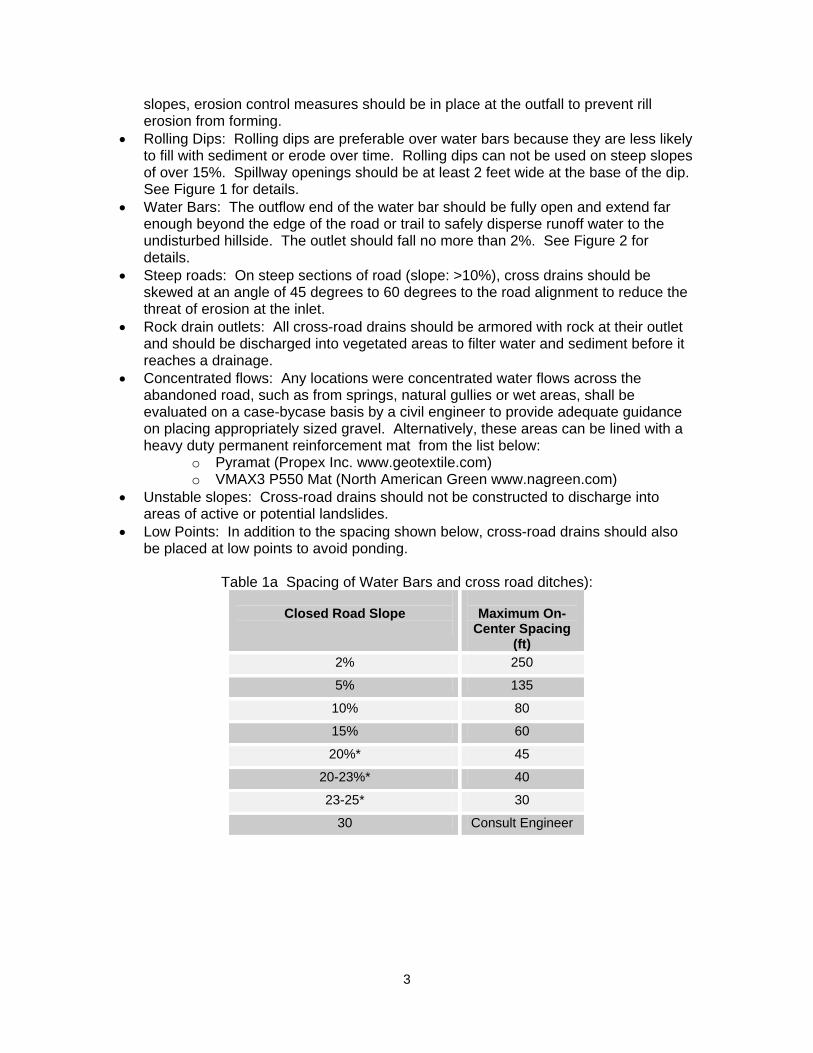
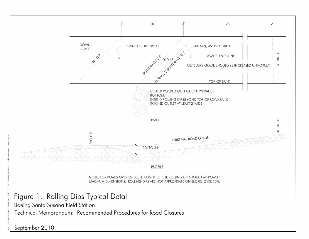
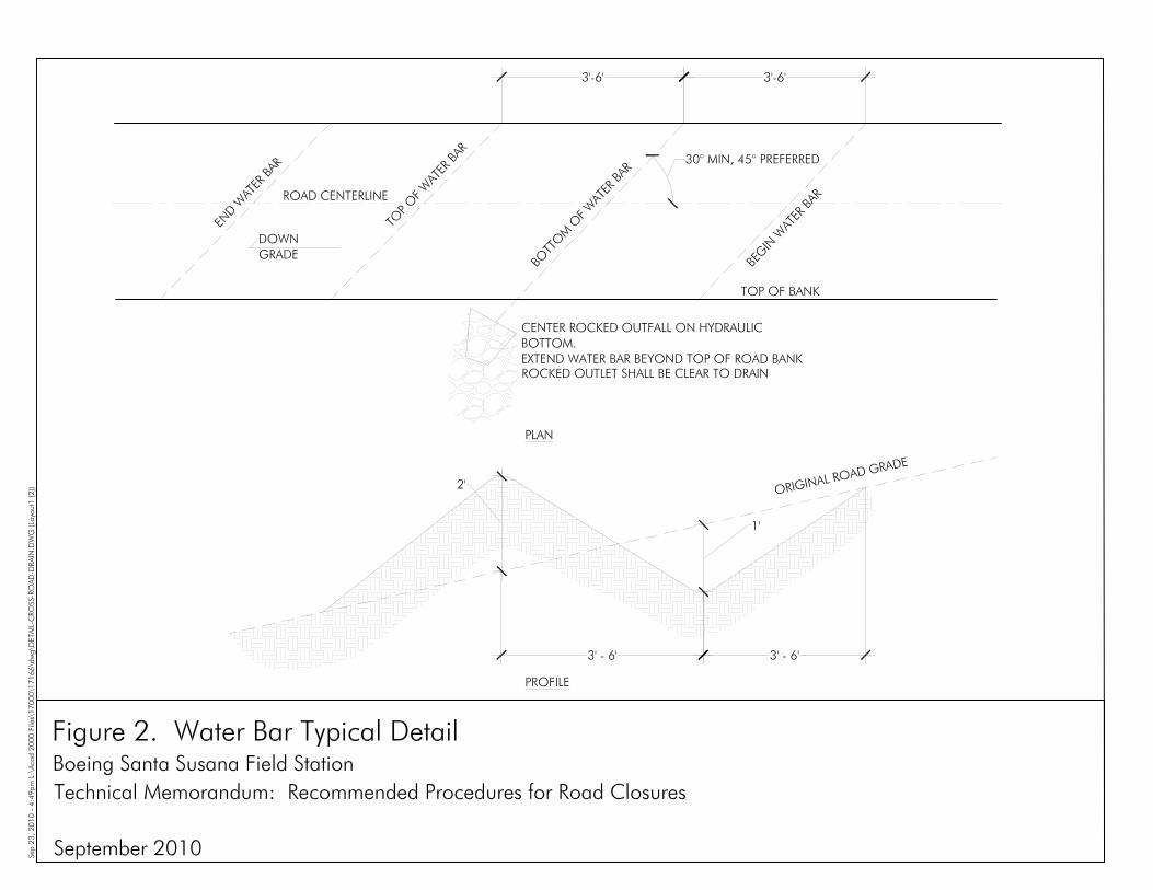
Cross road drains: On out-sloped roads that do not require cross-slope ditches, install water bars or rolling dips at regular intervals according to Table 1a and 1b below. On roads that have less than 10% slope, align cross-drains at a 30 degrees to 45 degrees to the centerline of the road. Cross road drains should be extended below the former road edge onto the steeper side slope to ensure water flow will not bypass the drain. The uphill end of the cross-drain should tie into the cutbank of the road.
Outfall Protection: Wherever cross road drains discharge concentrated flows onto
3
slopes, erosion control measures should be in place at the outfall to prevent rill erosion from forming.
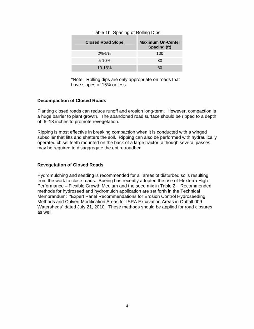
Rolling Dips: Rolling dips are preferable over water bars because they are less likely to fill with sediment or erode over time. Rolling dips can not be used on steep slopes of over 15%. Spillway openings should be at least 2 feet wide at the base of the dip. See Figure 1 for details.
Water Bars: The outflow end of the water bar should be fully open and extend far enough beyond the edge of the road or trail to safely disperse runoff water to the undisturbed hillside. The outlet should fall no more than 2%. See Figure 2 for details.
Steep roads: On steep sections of road (slope: >10%), cross drains should be skewed at an angle of 45 degrees to 60 degrees to the road alignment to reduce the threat of erosion at the inlet.
Rock drain outlets: All cross-road drains should be armored with rock at their outlet and should be discharged into vegetated areas to filter water and sediment before it reaches a drainage.
Concentrated flows: Any locations were concentrated water flows across the abandoned road, such as from springs, natural gullies or wet areas, shall be evaluated on a case-bycase basis by a civil engineer to provide adequate guidance on placing appropriately sized gravel. Alternatively, these areas can be lined with a heavy duty permanent reinforcement mat from the list below:
o Pyramat (Propex Inc. www.geotextile.com) o VMAX3 P550 Mat (North American Green www.nagreen.com)
Unstable slopes: Cross-road drains should not be constructed to discharge into areas of active or potential landslides.
Low Points: In addition to the spacing shown below, cross-road drains should also be placed at low points to avoid ponding.
Table 1a Spacing of Water Bars and cross road ditches):
Closed Road Slope
Maximum On-
Center Spacing (ft)
2% 250
5% 135
10% 80
15% 60
20%* 45
20-23%* 40
23-25* 30
30 Consult Engineer
4
Table 1b Spacing of Rolling Dips:
Closed Road Slope
Maximum On-Center
Spacing (ft) 2%-5% 100
5-10% 80
10-15% 60
*Note: Rolling dips are only appropriate on roads that have slopes of 15% or less.
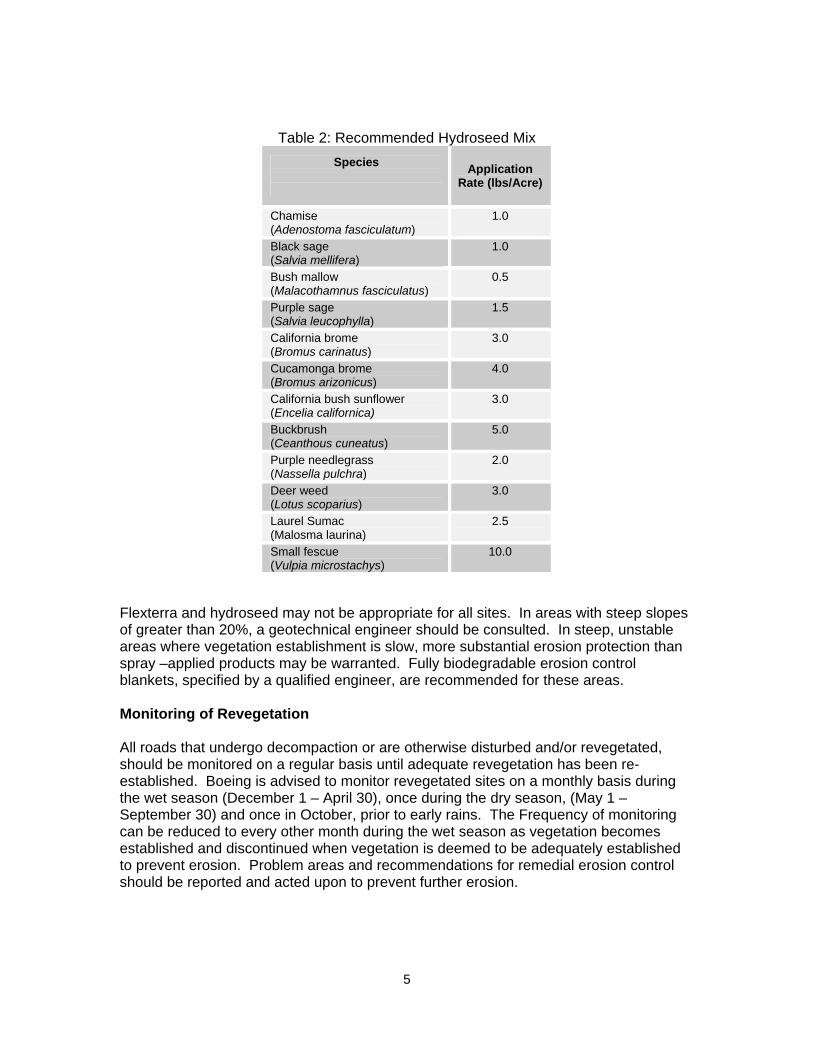
Decompaction of Closed Roads Planting closed roads can reduce runoff and erosion long-term. However, compaction is a huge barrier to plant growth. The abandoned road surface should be ripped to a depth of 6–18 inches to promote revegetation. Ripping is most effective in breaking compaction when it is conducted with a winged subsoiler that lifts and shatters the soil. Ripping can also be performed with hydraulically operated chisel teeth mounted on the back of a large tractor, although several passes may be required to disaggregate the entire roadbed. Revegetation of Closed Roads Hydromulching and seeding is recommended for all areas of disturbed soils resulting from the work to close roads. Boeing has recently adopted the use of Flexterra High Performance – Flexible Growth Medium and the seed mix in Table 2. Recommended methods for hydroseed and hydromulch application are set forth in the Technical Memorandum: “Expert Panel Recommendations for Erosion Control Hydroseeding Methods and Culvert Modification Areas for ISRA Excavation Areas in Outfall 009 Watersheds” dated July 21, 2010. These methods should be applied for road closures as well.
5
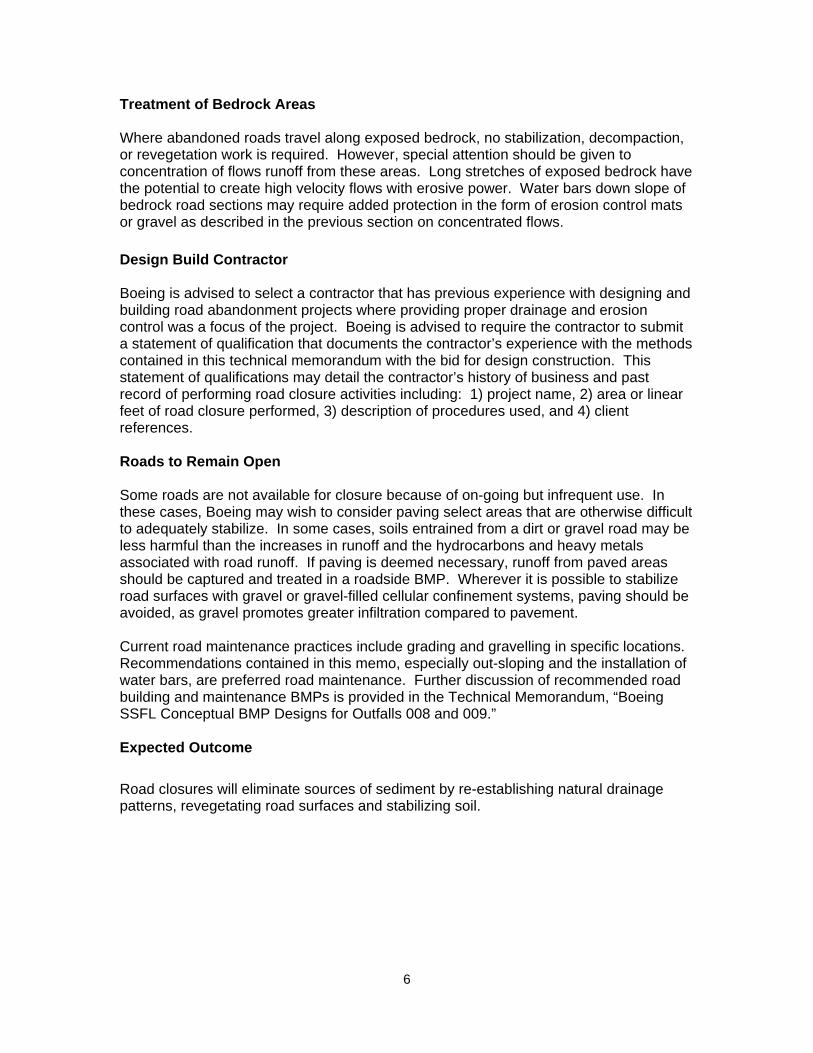
Table 2: Recommended Hydroseed Mix Species
Application Rate (lbs/Acre)
Chamise (Adenostoma fasciculatum)
1.0
Black sage (Salvia mellifera)
1.0
Bush mallow (Malacothamnus fasciculatus)
0.5
Purple sage (Salvia leucophylla)
1.5
California brome (Bromus carinatus)
3.0
Cucamonga brome (Bromus arizonicus)
4.0
California bush sunflower (Encelia californica)
3.0
Buckbrush (Ceanthous cuneatus)
5.0
Purple needlegrass (Nassella pulchra)
2.0
Deer weed (Lotus scoparius)
3.0
Laurel Sumac (Malosma laurina)
2.5
Small fescue (Vulpia microstachys)
10.0
Flexterra and hydroseed may not be appropriate for all sites. In areas with steep slopes of greater than 20%, a geotechnical engineer should be consulted. In steep, unstable areas where vegetation establishment is slow, more substantial erosion protection than spray –applied products may be warranted. Fully biodegradable erosion control blankets, specified by a qualified engineer, are recommended for these areas. Monitoring of Revegetation All roads that undergo decompaction or are otherwise disturbed and/or revegetated, should be monitored on a regular basis until adequate revegetation has been re-established. Boeing is advised to monitor revegetated sites on a monthly basis during the wet season (December 1 – April 30), once during the dry season, (May 1 – September 30) and once in October, prior to early rains. The Frequency of monitoring can be reduced to every other month during the wet season as vegetation becomes established and discontinued when vegetation is deemed to be adequately established to prevent erosion. Problem areas and recommendations for remedial erosion control should be reported and acted upon to prevent further erosion.
6
Treatment of Bedrock Areas Where abandoned roads travel along exposed bedrock, no stabilization, decompaction, or revegetation work is required. However, special attention should be given to concentration of flows runoff from these areas. Long stretches of exposed bedrock have the potential to create high velocity flows with erosive power. Water bars down slope of bedrock road sections may require added protection in the form of erosion control mats or gravel as described in the previous section on concentrated flows. Design Build Contractor Boeing is advised to select a contractor that has previous experience with designing and building road abandonment projects where providing proper drainage and erosion control was a focus of the project. Boeing is advised to require the contractor to submit a statement of qualification that documents the contractor’s experience with the methods contained in this technical memorandum with the bid for design construction. This statement of qualifications may detail the contractor’s history of business and past record of performing road closure activities including: 1) project name, 2) area or linear feet of road closure performed, 3) description of procedures used, and 4) client references. Roads to Remain Open Some roads are not available for closure because of on-going but infrequent use. In these cases, Boeing may wish to consider paving select areas that are otherwise difficult to adequately stabilize. In some cases, soils entrained from a dirt or gravel road may be less harmful than the increases in runoff and the hydrocarbons and heavy metals associated with road runoff. If paving is deemed necessary, runoff from paved areas should be captured and treated in a roadside BMP. Wherever it is possible to stabilize road surfaces with gravel or gravel-filled cellular confinement systems, paving should be avoided, as gravel promotes greater infiltration compared to pavement. Current road maintenance practices include grading and gravelling in specific locations. Recommendations contained in this memo, especially out-sloping and the installation of water bars, are preferred road maintenance. Further discussion of recommended road building and maintenance BMPs is provided in the Technical Memorandum, “Boeing SSFL Conceptual BMP Designs for Outfalls 008 and 009.” Expected Outcome Road closures will eliminate sources of sediment by re-establishing natural drainage patterns, revegetating road surfaces and stabilizing soil.

7
FIGURES & DETAILS
Environmental Sampling of Dioxins and Other Low Solubility Pollutants at Parts-per-Billion and Lower Concentrations:
Field Protocols for Collecting SSFL ISRA Performance Samples and Obtaining Replicate Splits Using a Dekaport Cone Splitter
Including Field Blanks and Laboratory Reporting Requirements for Identifying QA/QC Problems
Eugene R. Weiner
This report was prepared on behalf of and in collaboration with the Boeing Surface Water Expert Panel.
CONTENTS
1 INTRODUCTION ........................................................................................................ 1 2 SUMMARY OF FIELD PERFORMANCE SAMPLING PROCEDURES ...................... 2
2a Objectives..................................................................................................... 2 2b Field Quality Control (QC) ........................................................................... 2 2c Grab Sampling when Using a Cone Splitter ............................................... 3
3 STEP-BY-STEP FIELD PROCEDURES .................................................................... 5
3a Types of Sample Containers ....................................................................... 5 3b Field and Equipment QA/QC Blanks ........................................................... 6 3c Setting up the Cone Splitter for Use ........................................................... 6 3d Collecting Grab Samples to be used with the Cone Splitter ................... 10 3e Adding the Composited Sample to the Cone Splitter .............................. 11
4 REFERENCES CONSULTED .................................................................................. 13 APPENDIX A: Laboratory Reporting Requirements for Identifying Laboratory QA/QC Problems (Elizabeth Wessling) .............................................. 15 APPENDIX B: Filling the Compositing and Laboratory Containers
with the Correct Volumes ................................................................. 17 APPENDIX C: Initial Preparation and Performance Test of a New Cone Splitter .. 18 APPENDIX D: Cleaning the Cone Splitter ................................................................ 23 APPENDIX E: Inherent Variability in Parts-Per-Billion Analyses of Low-Solubility Pollutants ............................................................. 29
1
1. INTRODUCTION
Special sampling and analytical procedures are needed for measuring environmental
pollutants quantitatively at parts-per-billion concentrations or lower. Even slight
accidental sample contamination, which might not be significant in more routine
sampling programs, can cause serious errors when sampling for very low concentrations
of pollutants. It is important to use sampling protocols that minimize such errors, follow
the protocols carefully and consistently, and always include field quality control blanks
designed to help detect and quantify accidental contamination when it occurs.
Pollutants with low aqueous solubility, such as dioxins1, require additional special
attention because they tend to partition preferentially from the dissolved state to a sorbed
state on solid surfaces such as sediments and container walls. For low-solubility
pollutants, any sampling step that requires transferring a sample from the original
collection container to other containers has the potential for introducing quantitation
errors because sorbed pollutants are seldom transferred in a consistent manner. Sample
transfer difficulties are minimized by pre-rinsing collection and transfer containers and
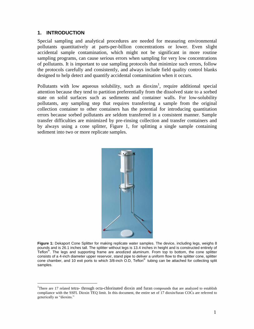
by always using a cone splitter, Figure 1, for splitting a single sample containing
sediment into two or more replicate samples.
Figure 1: Dekaport Cone Splitter for making replicate water samples. The device, including legs, weighs 8 pounds and is 26.1 inches tall. The splitter without legs is 13.4 inches in height and is constructed entirely of Teflon®. The legs and supporting frame are anodized aluminum. From top to bottom, the cone splitter consists of a 4-inch diameter upper reservoir, stand pipe to deliver a uniform flow to the splitter cone, splitter cone chamber, and 10 exit ports to which 3/8-inch O.D, Teflon® tubing can be attached for collecting split samples.
1There are 17 related tetra- through octa-chlorinated dioxin and furan compounds that are analyzed to establish
compliance with the SSFL Dioxin TEQ limit. In this document, the entire set of 17 dioxin/furan COCs are referred to
generically as “dioxins.”
2
2. SUMMARY OF FIELD PERFORMANCE SAMPLING PROCEDURES
2a. Objectives
The field performance sampling protocol has three main objectives:
1. To collect stormwater runoff samples that are acceptable representations of
environmental conditions at the place and time of sampling.
2. To store and transport these samples in a manner that maintains the important
physical and chemical properties of the sample. This generally requires that
samples are properly cooled and, if necessary, preservatives added and pH
adjusted as soon as possible after collection.
3. To prevent contamination of samples that can result in false analytical results.
In order to accomplish these objectives, all procedures that involve sample-handling must
be consistently controlled. This includes selecting, cleaning, and properly using
equipment such as sample splitters, sample containers, tubing, gloves, and other materials
that may come in contact with the sample, both in the field and during transport to the
laboratory.
Quality control checks (equipment and field blanks) are designed to test how well the
sampling procedures are executed. But even if all sampling procedures are performed
correctly, stormwater runoff is inherently heterogeneous and successive samples
collected from the same location will generally have some degree of variability in
composition. For this reason, when certain comparisons are required, such as comparing
analyses of the same sample by different laboratories or seeking correlations among
different water quality parameters (e.g., association of dioxins with sediments), it is
important to make all comparisons from splits of a single sample and not from different
samples, even if collected within a short time from the same location.
The greatest source of stormwater heterogeneity comes from spatial and temporal
fluctuations in total solids. This is because low solubility pollutants, like dioxins and
many metals, tend to concentrate in sediments by sorption. Replicate samples that vary
significantly in solids concentration will also have less agreement in chemical pollutant
concentrations. Using a cone splitter to obtain replicate samples by splitting a single
sample has been shown to improve reproducibility among replicate samples split from a
single sample containing sediment. The care and use of a cone splitter is described in this
report.
2b. Field Quality Control (QC)
Equipment and field QC blanks should be obtained to determine if positive detects have
been influenced by field sampling and sample splitting activities. Since contaminant of
concern (COC) detects for metals and dioxins are expected, one equipment rinsate
(equipment blank) per event should be analyzed to represent the decontamination
3
process. Additional equipment rinsates should be collected and placed on hold, to be
analyzed if unusual detects are noted in the site samples.
These equipment and field QC procedures apply to sampling for all COCs. QC blanks
generated during sampling activities are necessary to provide assurance that positive
detects for COCs are not from accidental contamination during sampling.
Equipment Blanks: Obtain from the laboratory a sample of reference laboratory
blank-grade water known to be initially free of contaminant analytes (e.g., dioxins
and metal COCs). Use this clean water as a final rinse when cleaning sampling
equipment. The equipment blank is used to check the effectiveness of
decontamination procedures or to verify that new materials (containers, tubing,
etc.) in contact with environmental samples do not contribute COCs. For example,
one equipment blank should be poured through the cleaned cone splitter, collected
from each outlet tube, and composited into a normal sample container for
laboratory analysis.
Field Blanks: These blanks are prepared during sampling by filling a clean
container with COC-free laboratory blank-grade water and treating it in a manner
that allows ambient sources of COCs other than storm runoff to be detected. For
example, one field blank should be exposed to the atmosphere at the sampling site
for at least as long as collected samples are exposed, so that airborne
contaminants can be detected. If it is raining, protect the airborne blank from the
rain during atmospheric exposure.
If the “COC-free” laboratory blank-grade water or preservative becomes suspect,
an unopened QC blank containing only laboratory blank-grade water and
preservative (if used) should be tested.
Equipment and field blanks should be retained and analyzed only if there are positive
detects in the samples. Should there be positive detections for COCs, the contract
laboratory should be able to eliminate itself as a source of contamination by providing its
laboratory method blank and instrument background checks. The combination of
equipment blanks, field blanks, occasional laboratory verification blanks, and the
laboratory’s background checks can be used to identify whether positive detections are
field-related, laboratory-related, or sample-related.
2c. Grab Sampling When Using a Cone Splitter
Single grab samples represent the conditions that exist in the source at the moment the
sample is collected and do not necessarily represent conditions at any other time.
However, since more than one sample is normally required from a given site for each
sampling event, it is best to always use a cone splitter for filling sample bottles. This is
because all COCs will sorb to some extent to sediments and using the cone splitter
assures the maximum uniformity of sediment distribution among the samples.
4
The cone splitter has a 4-liter reservoir and works best with water sample volumes of 3-4
liters because:
1. It is important to pour the entire collected water sample through the splitter at one
time. Some sediment settles quickly and may remain behind. When the entire
collected water sample is poured through the splitter at one time, with care to
completely empty the pouring container, problems with rapid settling of particles
during pouring are minimized.
2. It also is important to maintain, during most of the pour, a substantial water
pressure head above the standpipe to the splitter cone. This helps to maintain a
uniform pressure drop in all of the pathways to the sample containers, prevents air
from entering the splitting block while transferring the sample, and facilitates an
even division of the sample.
Thus, it generally will be necessary to repetitively collect a number of smaller grab
samples from the source and transfer them to a compositing container (approximately 1-
gallon or larger) in order to obtain a sufficient volume for pouring through the cone
splitter. A side benefit of this procedure is that the repeated collection and compositing of
smaller samples provides a degree of time and flow integration that helps smooth small
temporal and spatial variations in the source sediment composition.
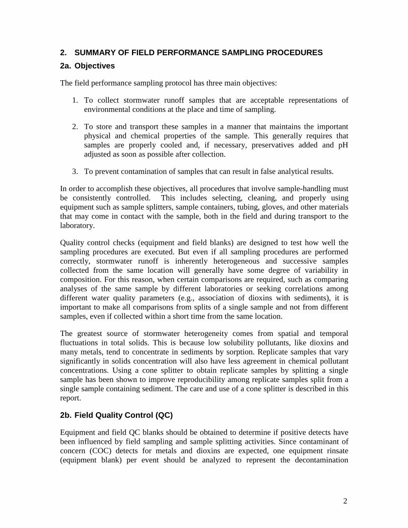
Bottles for different analyses (e.g., metals and dioxins) and different sized sample
containers with or without preservatives can be connected to the splitter at the same time
(see Figure 2).
Figure 2: Cone splitter with different kinds of collection containers attached. The three plastic containers are each connected to two outlet ports for collecting larger sample volumes.
5
3. STEP-BY-STEP FIELD PROCEDURES
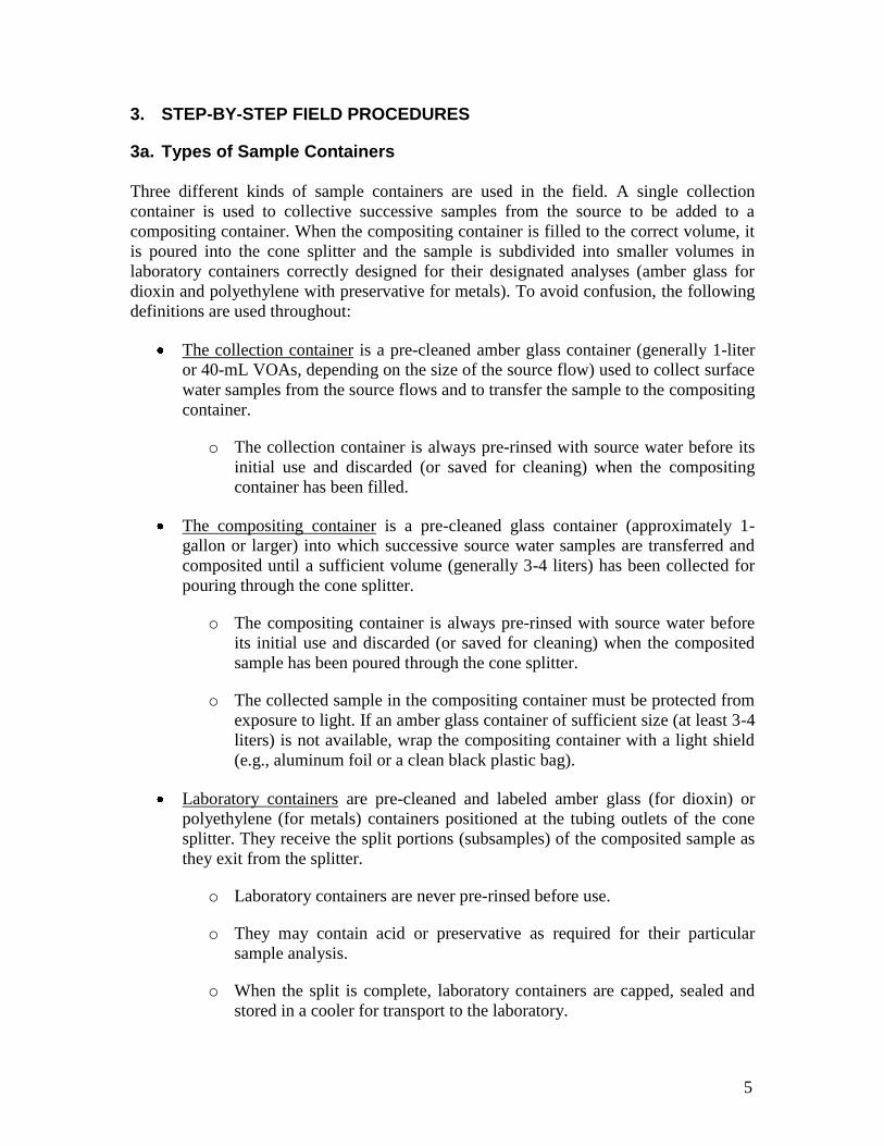
3a. Types of Sample Containers Three different kinds of sample containers are used in the field. A single collection
container is used to collective successive samples from the source to be added to a
compositing container. When the compositing container is filled to the correct volume, it
is poured into the cone splitter and the sample is subdivided into smaller volumes in
laboratory containers correctly designed for their designated analyses (amber glass for
dioxin and polyethylene with preservative for metals). To avoid confusion, the following
definitions are used throughout:
The collection container is a pre-cleaned amber glass container (generally 1-liter
or 40-mL VOAs, depending on the size of the source flow) used to collect surface
water samples from the source flows and to transfer the sample to the compositing
container.
o The collection container is always pre-rinsed with source water before its
initial use and discarded (or saved for cleaning) when the compositing
container has been filled.
The compositing container is a pre-cleaned glass container (approximately 1-
gallon or larger) into which successive source water samples are transferred and
composited until a sufficient volume (generally 3-4 liters) has been collected for
pouring through the cone splitter.
o The compositing container is always pre-rinsed with source water before
its initial use and discarded (or saved for cleaning) when the composited
sample has been poured through the cone splitter.
o The collected sample in the compositing container must be protected from
exposure to light. If an amber glass container of sufficient size (at least 3-4
liters) is not available, wrap the compositing container with a light shield
(e.g., aluminum foil or a clean black plastic bag).
Laboratory containers are pre-cleaned and labeled amber glass (for dioxin) or
polyethylene (for metals) containers positioned at the tubing outlets of the cone
splitter. They receive the split portions (subsamples) of the composited sample as
they exit from the splitter.
o Laboratory containers are never pre-rinsed before use.
o They may contain acid or preservative as required for their particular
sample analysis.
o When the split is complete, laboratory containers are capped, sealed and
stored in a cooler for transport to the laboratory.
6
3b. Field and Equipment QA/QC Blanks
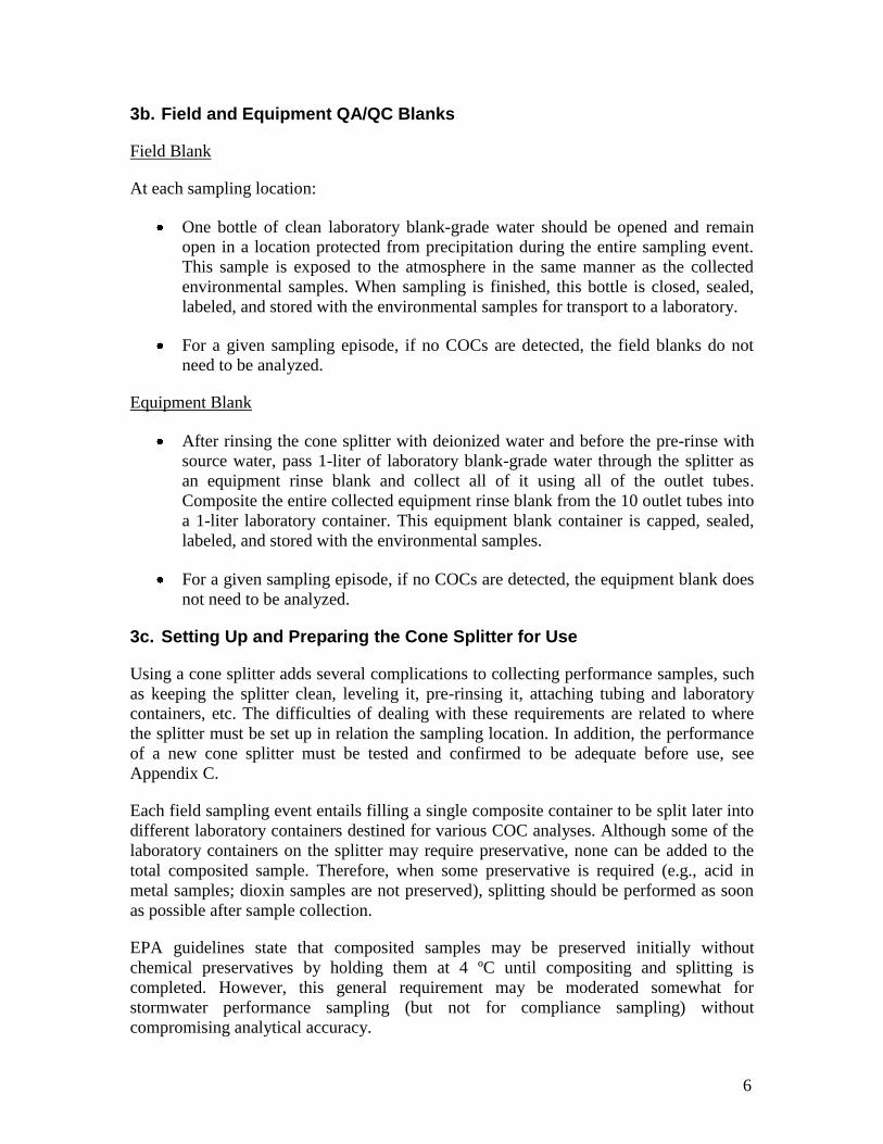
Field Blank
At each sampling location:
One bottle of clean laboratory blank-grade water should be opened and remain
open in a location protected from precipitation during the entire sampling event.
This sample is exposed to the atmosphere in the same manner as the collected
environmental samples. When sampling is finished, this bottle is closed, sealed,
labeled, and stored with the environmental samples for transport to a laboratory.
For a given sampling episode, if no COCs are detected, the field blanks do not
need to be analyzed.
Equipment Blank
After rinsing the cone splitter with deionized water and before the pre-rinse with
source water, pass 1-liter of laboratory blank-grade water through the splitter as
an equipment rinse blank and collect all of it using all of the outlet tubes.
Composite the entire collected equipment rinse blank from the 10 outlet tubes into
a 1-liter laboratory container. This equipment blank container is capped, sealed,
labeled, and stored with the environmental samples.
For a given sampling episode, if no COCs are detected, the equipment blank does
not need to be analyzed.
3c. Setting Up and Preparing the Cone Splitter for Use
Using a cone splitter adds several complications to collecting performance samples, such
as keeping the splitter clean, leveling it, pre-rinsing it, attaching tubing and laboratory
containers, etc. The difficulties of dealing with these requirements are related to where
the splitter must be set up in relation the sampling location. In addition, the performance
of a new cone splitter must be tested and confirmed to be adequate before use, see
Appendix C.
Each field sampling event entails filling a single composite container to be split later into
different laboratory containers destined for various COC analyses. Although some of the
laboratory containers on the splitter may require preservative, none can be added to the
total composited sample. Therefore, when some preservative is required (e.g., acid in
metal samples; dioxin samples are not preserved), splitting should be performed as soon
as possible after sample collection.
EPA guidelines state that composited samples may be preserved initially without
chemical preservatives by holding them at 4 ºC until compositing and splitting is
completed. However, this general requirement may be moderated somewhat for
stormwater performance sampling (but not for compliance sampling) without
compromising analytical accuracy.
7
In surface water runoff, the more rapid metal chemical and biological changes
(hydrolysis, redox change, sorption to sediment, dissolution, and precipitation), that
preservation is intended to minimize, have mostly already occurred by the time the
samples are collected. Adding acid to unfiltered metal stormwater samples is more a
matter of converting all samples to the same state of dissolved metals, than it is of
preserving the state of the sample at the time of collection. Therefore, adding preservative
to metal stormwater samples may be delayed a few hours to allow multiple sites to be
sampled before composite samples are transported to a “clean area” not subject to
contamination for splitting.
Every step in the detailed procedures below should be performed in the same way every
time to help assure unbiased results. For example, one should always wet the cone splitter
first with deionized water and then with source water before a split and always tap the
splitter at the end of a split to release adhering droplets.
1. If it can be done within about 5 hours, it is acceptable to transport the composited
samples a short distance within the SSFL from the sampling site to the splitter.
a) Each composited sample should be split as soon as possible, up to about 5
hours.
i) The 5 hour limit is a guideline, not a firm rule. It was selected by “best
professional judgment” to allow time for sampling multiple sites before
having to perform the splitting procedure. If it is found to be insufficient,
tests should be performed to determine whether longer delays before
splitting will affect analytical results.
b) During filling at the site, the composite container should be wrapped with
aluminum foil or a clean, black plastic bag to protect against light exposure,
and kept in a cooler at no more than 4 ºC.
c) After filling, the composite container should be securely capped, labeled with
pertinent information, and stored in a cooler at no more than 4 ºC until
splitting is completed.
2. If possible, it is best to set the splitter up in an enclosed building space near the
sampling sites that can be used as an ad-hoc laboratory. A space should be chosen
that can be maintained in a clean condition and, ideally, can be reserved for
sampling-related activities only.
a) Next best would be to set the splitter up in an enclosed van or truck.
b) If necessary, set the splitter up in the field at the sampling site.
i) Try to select a field location close to the sample collection point and as
level as feasible. If it is raining, protect the splitter from precipitation with
some appropriate cover, such as a plastic tent.
8
3. Visually inspect the pre-cleaned cone splitter (see Appendix D) for any problems,
such as broken or dirty parts, misalignment, or foreign material, especially in
threaded parts such as tubing connectors.
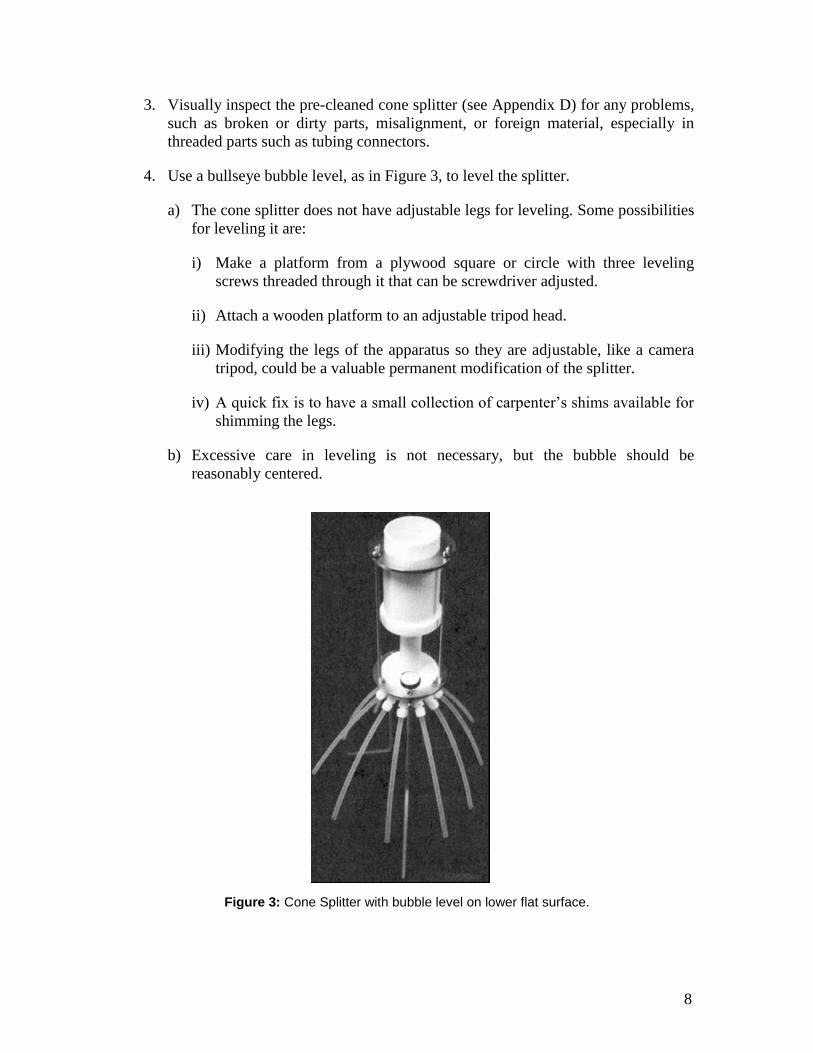
4. Use a bullseye bubble level, as in Figure 3, to level the splitter.
a) The cone splitter does not have adjustable legs for leveling. Some possibilities
for leveling it are:
i) Make a platform from a plywood square or circle with three leveling
screws threaded through it that can be screwdriver adjusted.
ii) Attach a wooden platform to an adjustable tripod head.
iii) Modifying the legs of the apparatus so they are adjustable, like a camera
tripod, could be a valuable permanent modification of the splitter.
iv) A quick fix is to have a small collection of carpenter’s shims available for
shimming the legs.
b) Excessive care in leveling is not necessary, but the bubble should be
reasonably centered.
Figure 3: Cone Splitter with bubble level on lower flat surface.
9
5. Securely connect pre-cleaned fluorocarbon (Teflon®) tubing to each outlet.
a) Every outlet must have an identical tube (equal diameters and lengths)
attached to assure uniform flow conditions at each outlet. No outlets should be
closed to flow.
b) When pre-rinsing the splitter, outlet tubes can empty rinse water to a waste
container.
c) When collecting split samples, outlet tubes are inserted into the laboratory
containers that receive the splits for analyses. Tubes not used for split samples
can empty to a waste container.
d) Containers will generally have to be supported so their openings are at the
same level and to assure they cannot accidentally be tipped over during
splitting.
i) If the same container arrangement is always used, the wooden platform
used for leveling can be fitted with wooden blocks predrilled to hold the
containers securely at the correct heights.
ii) For greater flexibility, short lengths of 2-inch aluminum angle stock can
be mounted vertically at each container position on the leveling platform.
Containers can be attached securely to the open side of the angle with
small bungee cords and with wooden blocks beneath the containers to
adjust their heights.
iii) Aluminum rods, with three-finger laboratory clamps and clamp holders
can be substituted for the setup in ii.
6. Wet the splitter and attached tubing by pouring through 1 or 2 liters of deionized
water. Lightly tap the system to dislodge adhering water drops and discard all the
water.
7. Rinse again, this time using 2 to 4 liters of the source water to be sampled. Lightly
tap the system to dislodge adhering water drops and discard all the water. Place
laboratory containers under the outlet tubes.
a) Laboratory containers are never pre-rinsed before use.
b) Outlet tubes should enter the container opening to avoid spilling, but should
not become submerged below the sample surface. This insures that different
back pressures at the tubing exits do not influence flow rates.
c) Laboratory containers used for dioxin analysis should be protected from light
exposure. Use amber glass containers or wrap containers with a light shield
such as aluminum foil.
10
d) Two or more outlet tubes can be combined into a single container to collect
different volumes of the original sample, see Figure 2 and Appendix B.
i) If combining multiple outlet tubes into a single container, make sure all
tubes permit free flow so that no unequal back pressures can develop.
e) Direct sample discharge from unused outlet tubes to a waste container.
3d. Collecting Grab Samples To Be Used with the Cone Splitter
Use only pre-cleaned glass sample collection and compositing containers. The collection
container should be a wide-mouth amber glass bottle of convenient size for immersing
into the source flow (up to 1-liter) and the compositing container should be a clean,
minimum of 1-gallon glass bottle, either amber colored or wrapped with a light shield,
which is filled repeatedly as necessary from the collection container. Both containers
should have clean closure caps with Teflon® seals.
1. Wear disposable powder-free nitrile gloves when sampling or handling sampling
equipment, including the cone splitter.
a) When holding any sample container for collecting, pouring, labeling, or any
other activity, keep your gloved hands away from the region of the container
opening, even if it is capped, in order to prevent contaminating the sample.
Contamination of a sample is still possible when a capped container that was
contaminated near its opening in the field is re-opened in the laboratory.
2. Prepare both the pre-cleaned collection and compositing containers by pre-rinsing
each at least 3 times with the water being sampled. Exposing sorption sites on the
container walls to COCs in the rinse water will minimize additional sorption from
the samples.
a) Pre-rinsing needs to be done only once for both containers, prior to collecting
the first sample from the source and starting to fill the compositing container
for pouring through the splitter.
b) When pre-rinsing the collection and compositing containers, cap and shake
them to also expose the inside surface of the cap to the rinse water.
c) For flows too small to collect into a 1-liter collection container, use a sample-
rinsed standard 40-mL amber glass VOA vial. Do not collect from small flows
into a container with a small entrance opening (such as a syringe), as this
preferentially biases the sample against large sediment particle sizes.
d) Keep the compositing container capped except when pouring collected
samples into it.
11
3. Collect an environmental sample by submerging the collection container in a
central portion of the flow, opening first.
a) While in the flow, position the collection container so its opening is pointing
into the flow to fill it.
b) Hold the collection container on its body away from its opening.
c) Avoid stirring up settled sediments. If necessary, use a smaller container.
d) Return the filled container quickly to the surface.
4. Pour the sample from the filled collection container into the compositing
container and recap the compositing container until the next grab sample is added.
5. Repeat steps 3 and 4 (without additional pre-rinsing of the collection bottle) until
3 to 4 liters of sample have been transferred to the compositing container.
a) It is important that the entire sample in the compositing container is poured
through the splitter to avoid leaving any sediment behind.
b) For this reason, it is best to try to collect just enough total sample in the
compositing container to fill all the laboratory containers with the desired
volumes for laboratory analyses. Too little is better than too much because
any sediment left in the compositing container after pouring will be biased
toward larger sediment sizes.
c) Appendix B describes a procedure for filling the compositing and laboratory
containers with the correct volumes.
6. After each sampling event, discard the sample collection containers (or return
them to the laboratory for cleaning). Do not reuse them for another sampling
event. Simple rinsing of the containers with deionized or distilled water is not
acceptable.
a) The most common source of field-related COC contamination is from re-use
of sampling equipment and containers (grab samplers, tubing, buckets,
containers, etc.) because COCs, especially dioxins, can concentrate into low
solubility organic layers that build-up on the container wall with re-use.
3e. Adding the Composited Sample to the Cone Splitter
1. Shake the sample in the capped compositing container for 10 to 15 seconds.
2. Quickly uncap the compositing container and invert it over the cone splitter top
reservoir, allowing it to fully empty into the splitter. You are trying to prevent
significant settling of sediments while pouring.
12
a) Position the splitter low enough so the compositing container does not have to
be lifted too high into an awkward position for easy pouring.
b) When smaller containers are used, they may be rested it on the reservoir top.
c) It may be necessary to place a filter screen over the reservoir opening to
capture debris from sediment, plants or insects that could potentially clog the
splitter.
i) If required, captured debris can be removed from the screen and analyzed
separately.
ii) Carefully cleaned (and tested by analyzing equipment blanks) fiberglass
window screening may be used.
3. After the flow has stopped, tap the compositing container and splitter assembly to
dislodge adhering drops into the attached laboratory containers.
a) Visually examine all attached laboratory containers. Water levels should be
the same in identical containers. If not, examine the splitter and outlet tubing
for partial clogging, out-of-level positioning, or misaligned components.
b) If any problems are found, correct them, pour all subsamples back into the
composite container (if no preservatives were in the sample bottles), and split
again.
i) Such problems are expected to be rare, but the possibility might be a good
reason to wait until laboratory samples are removed from the splitter
before adding preservative (unless containers are routinely obtained from
the laboratory with preservatives already added).
4. Remove laboratory containers from the splitter, cap them securely, attach
identifying labels, and place containers into the storage cooler for transport,
concluding the sample splitting event.
a) Sample containers can be placed in separate Ziploc bags to prevent labels
from blurring by moisture or falling off and getting lost.
5. After each splitting event, discard the sample compositing containers (or return
them to the laboratory for cleaning). Do not reuse them for another splitting event.
Simple rinsing of the containers with deionized or distilled water is not
acceptable.
a) The most common source of field-related COC contamination is from re-use
of sampling equipment and containers (grab samplers, tubing, buckets,
containers, etc) because COCs, especially dioxins, can concentrate into low
solubility organic layers that build-up on the container wall with re-use.
13
6. The cone splitter must be rinsed with at least 3-liters of deionized water after each
composite split from the same site and runoff event.
a) The splitter must be Level 1-cleaned after each composite split from different
sites on the same day, and Level 2-cleaned after all samples collected on the
same day have been split, see Appendix D.
4. REFERENCES CONSULTED
1. “National Field Manual for the Collection of Water-Quality Data: Chapter A2.,
Selection of Equipment for Water Sampling”, Version 2.0, Revised by Susan L. Lane,
Sarah Flanagan, and Franceska D. Wilde; Edited by Franceska D. Wilde, Dean B.
Radtke, Jacob Gibs, and Rick T. Iwatsubo, U.S. Geological Survey Book 9 of
Handbooks for Water-Resources Investigations, 3/2003 TWRI.
http://water.usgs.gov/owq/FieldManual/Chapter2-Archive/Archive/Ch2.pdf
2. “National Field Manual for the Collection of Water-Quality Data, Chapter A3,
Cleaning of Equipment for Water Sampling”, Revised 2004, Edited by Franceska D.
Wilde, Book 9 of: Handbooks for Water-Resources Investigations, U.S. Geological
Survey, Techniques of Water-Resources Investigations Book 9,
http://water.usgs.gov/owq/FieldManual/chapter3/final508Chap3book.pdf
3. “National Field Manual for the Collection of Water-Quality Data, Chapter A4,
Collection of Water Samples”, Edited by: F.D. Wilde, D.B. Radtke, Jacob Gibs, and
R.T. Iwatsubo, Book 9 of: Handbooks for Water-Resources Investigations, U.S.
Geological Survey, Techniques of Water-Resources Investigations Book 9, 9/99
http://water.usgs.gov/owq/FieldManual/chapter4/pdf/Chap4_v2.pdf
4. “Measuring Solids Concentration in Stormwater Runoff: Comparison of Analytical
Methods”, Clark, S.E.; Siu, C.Y.S., Environ. Sci. Technol., 42, 511–516 (2008)
5. “Comparison of Stormwater Solids Analytical Methods for Performance Evaluation
of Manufactured Treatment Devices”, Clark, S.E.; Pitt, R., J. Environ. Eng., 134,
259–264 (2008)
6. “Errors Associated with Solids Measurement in Stormwater Runoff”, Siu, C.Y.S.;
Clark, S. E.; Pitt, R., Proceedings of the World Water and Environmental Resources
Congress 2008, Honolulu, Hawaii, May 13–16; American Society of Civil Engineers:
Reston, Virginia.
7. “Protocols for Quantifying Solids Removal Performance during Controlled Testing of
Manufactured Treatment Devices”, Khambhamettu, U., Clark, S.E., and Pitt, R.,
Restoring our Natural Habitat, Proceedings of the World Environmental and Water
Resources Congress 2007, Tampa, Florida, May 15–19; American Society of Civil
Engineers: Reston, Virginia.

14
8. “Cleaning a Cone Splitter” Office of Water Quality Technical Memorandum 97.03,
Subject: Protocols for Cleaning a Teflon Cone Splitter to Produce Contaminant-Free
Subsamples for Subsequent Determinations of Trace Elements,
http://water.usgs.gov/admin/memo/QW/qw97.03.html
15
APPENDIX A
Laboratory Reporting Requirements for Identifying Laboratory QA/QC Problems
(Elizabeth Wessling)
In order to accurately compare sample results from different laboratories, it is necessary
to evaluate all aspects of the sample preparation and analysis. To accomplish this
evaluation, all laboratory documentation from time of receipt to reporting of the sample
results for each analytical method along with the associated QC information must
supplied by the laboratories. The following outlines the documentation that must be
provided for each general type of analysis.
All sample receiving information including the executed chain-of-custody, airbills,
sample receipt checklists, sample delivery group (SDG) assignment sheet, and any other
correspondence relevant to the SDG will be provided.
Organics
Case Narrative inclusive of each analytical method:
Sample Result Forms (one complete sample result form for each analysis,
reanalysis, or dilution analysis)
Surrogate Recovery Forms (may be included on the sample result form)
MS/MSD Summary Forms
LCS/LCSD Summary Forms
Method Blank Summary Forms
Tuning and Mass Calibration (GCMS methods)
Initial Calibration
Continuing Calibration
Sample Run Logs GC
Internal Standard (Isotope Dilution) Recovery Summary
Intercolumn Comparison for GC
In addition to the summary information, all supporting raw data (chromatograms,
quantitation sheets, and spectra) for all samples, standards, tunes, QC samples, percent
solid calculations, benchsheets, and run logs must be included in the data package.
Inorganics
Case Narrative inclusive of each analytical method:
Sample Result Forms
Part 1 Initial and Continuing Calibration Verification
Part 2 CRDL Standard
Blanks
ICP Interference Check Sample
ICPMS Tune for ICPMS methods
Internal Standards for ICPMS
Spike Sample Recovery
16
Post Digestion Spike Sample Recovery (if performed)
Duplicates
Laboratory Control Sample
Standard Addition Results (if performed)
ICP Serial Dilutions
ICP Interelement Correction Factors
ICP Linear Range
Preparation Logs
Analysis Run Logs
In addition to the summary information all supporting raw data for all samples, standards,
QC samples, percent solid calculations, distillation logs, digestion logs, benchsheets, and
run logs will be included in the data package. All sample receiving information including
the executed chain-of-custody, airbills, sample receipt checklist, SDG assignment sheet,
and any other correspondence relevant to the SDG will be provided.
17
APPENDIX B
Filling the Compositing and Laboratory Containers with the Correct Volumes
Outlet tubes can be combined into a single container to collect various volume
combinations of the original composited sample. Care must be taken however, when
combining outlet tubes into one container, to make sure there is no backpressure resulting
from bending the tubing in ways that restrict their flow.
Since the composited sample is always split into 10 equal parts, it is convenient to choose
a total composited volume such that required laboratory sample volumes are close to a
simple multiple of 1/10 of the composited volume.
Suppose that the following laboratory samples are required from a particular site: two 1-L
splits for dioxin analysis and four 250-mL splits for metal analyses. A convenient
collection scenario would be:
Collect a composite volume of 4.5-L, which the splitter will divide into ten 450-
mL portions.
Connect each of the two 1-L laboratory containers to two adjacent outlet tubes.
After splitting, each 1-L container will contain 900-mL of sample, which is
probably close enough to the needed 1-L.
Connect each of four 500-mL containers to one outlet tube. After splitting, each
500-mL container will contain 450-mL, with enough room to add acid for pH
adjustment.
Only 8 of the outlet tubes have been used, collecting a total of 3600 mL. Since no
splitter outlet must ever be closed off, the two unneeded outlet tubes must be
allowed to discharge the excess 900 mL to a waste container.
18
APPENDIX C
Initial Preparation and Performance Test of a New Cone Splitter (Adapted from Reference 1)
1. Prepare a Splitter Performance Test Notebook (SCN) in which to record and save
data from the inspection and Performance Test procedures below. Prepare the pages
so that relevant observations can be conveniently checked off or notations made
concerning the steps below. Date and initial each entry page as it is used.
2. Visually inspect the cone splitter and all of its parts for cleanliness and clean if
necessary. Note relevant observations in the SCN.
3. Inspect the cone splitter housing and outlet ports. They should be smooth and
symmetrical without any burrs or machining defects visible. Note relevant
observations in the SCN.
4. Place the splitter on a stable platform or bench in a level position. Level it, preferably
with a bulls-eye bubble level as in Figure 3, by shimming its legs. Note relevant
observations in the SCN.
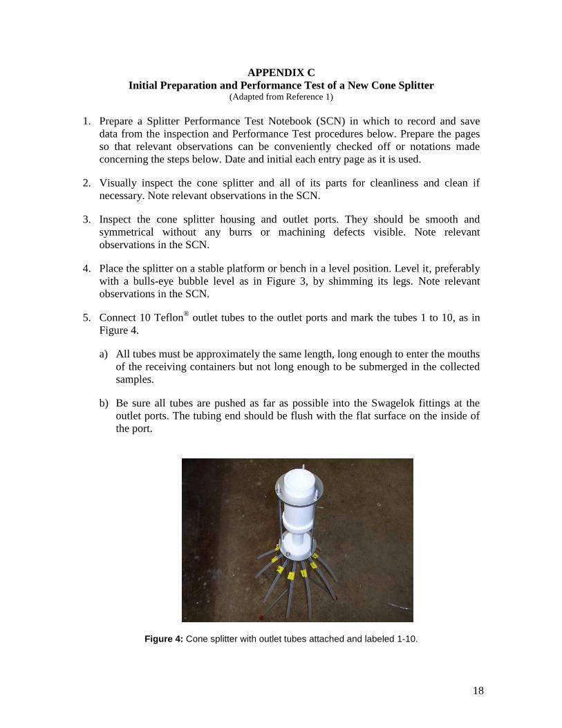
5. Connect 10 Teflon® outlet tubes to the outlet ports and mark the tubes 1 to 10, as in
Figure 4.
a) All tubes must be approximately the same length, long enough to enter the mouths
of the receiving containers but not long enough to be submerged in the collected
samples.
b) Be sure all tubes are pushed as far as possible into the Swagelok fittings at the
outlet ports. The tubing end should be flush with the flat surface on the inside of
the port.
Figure 4: Cone splitter with outlet tubes attached and labeled 1-10.
19
6. Place receiving containers under the tubes.
a) Outlet tubes should enter the container opening to avoid spilling, but should not
become submerged below the sample surface. This insures that different back
pressures at the tubing exits do not influence flow rates.
7. Wet and superficially clean the cone splitter by rinsing 2-3 liters of deionized water
through it and discard the water.
a) After rinsing, tap the apparatus to dislodge adhering water drops
8. Replace empty containers under each outlet.
9. Accurately measure approximately 3-4 liters of tap water into a l-gallon plastic bottle.
a) Record the value in the SCN.
10. Rapidly invert the 1-gallon bottle over the reservoir, letting it flow as fast as possible.
Rest the inverted bottle on top of the reservoir if desired.
a) For proper operation, the splitter stand-pipe must be full and discharging at its full
flowing capacity.
11. After all water has passed through the splitter, tap the assembly several times to
dislodge adhering water drops.
a) Check for spills and leaks. If any are observed, discard the test, correct the
problem, and repeat the test.
12. Accurately measure the volumes of the 10 subsamples within ±1 mL (e.g., use a
graduated cylinder). Record the volumes for each outlet in the SCN.
13. Repeat the test five more times for a total of six tests. Use approximately the same
initial volume for each test.
Calculating Cone Splitter Performance Test Statistics
A Microsoft Excel spreadsheet application is provided to make all the necessary
performance test statistical calculations from entered data. When data from the SCN is
entered, the spreadsheet calculates:
For each of the 6 tests:
1. Total recovered sample volume.
2. Sample volume loss in splitter.
3. Average of outlet volumes.

20
4. Error (deviation from the average) for each subsample volume.
5. Standard deviation of all subsamples
6. Percent standard deviation
For the set of 6 tests:
1. Average total recovered volume.
2. Average outlet volume over all tests for each outlet.
3. Average percent error over all tests for each outlet.
4. Average standard deviation over all tests.
5. Average percent deviation over all tests.
Note the error patterns for individual outlets into the SCN, to determine which outlets
show consistent bias. If significant, mark them with their average percent bias error.
The cone splitter is considered acceptable for sample processing if the average
percent deviation for all 6 tests is 3.0 percent or less, and no individual outlet error
exceeds ± 5.0 percent.
Table 1 is an example cone splitter performance test using the Excel spreadsheet.
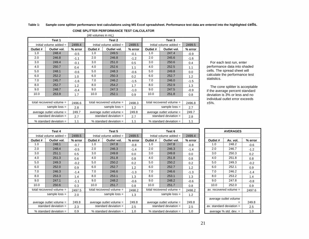
21
Table 1: Sample cone splitter performance test calculations using MS Excel spreadsheet. Performance test data are entered into the highlighted cells.
CONE SPLITTER PERFORMANCE TEST CALCULATOR (All volumes in mL)
Test 1 Test 2 Test 3
Initial volume added = 2499.4 Initial volume added = 2499.5 Initial volume added = 2499.5 Outlet # Outlet vol. % error Outlet # Outlet vol. % error Outlet # Outlet vol. % error
1.0 248.4 -0.5 1.0 249.5 -0.1 1.0 247.4 -0.9 2.0 246.8 -1.1 2.0 246.8 -1.2 2.0 245.6 -1.6
For each test run, enter performance data into shaded cells. The spread sheet will calculate the performance test statistics.
The cone splitter is acceptable
if the average percent standard deviation is 3% or less and no individual outlet error exceeds ±5%.
3.0 249.4 -0.1 3.0 251.0 0.5 3.0 250.6 0.4 4.0 250.7 0.4 4.0 252.6 1.1 4.0 252.5 1.1 5.0 248.1 -0.6 5.0 248.3 -0.6 5.0 249.8 0.0 6.0 252.2 1.0 6.0 250.3 0.2 6.0 252.7 1.2 7.0 245.7 -1.6 7.0 246.2 -1.5 7.0 246.0 -1.5 8.0 252.7 1.2 8.0 254.2 1.7 8.0 252.9 1.3 9.0 248.7 -0.4 9.0 247.3 -1.0 9.0 247.5 -0.9 10.0 253.9 1.7 10.0 252.1 0.9 10.0 251.8 0.8
total recovered volume = 2496.6 total recovered volume = 2498.3 total recovered volume = 2496.8
sample loss = 2.8 sample loss = 1.2 sample loss = 2.7 average outlet volume = 249.7 average outlet volume = 249.8 average outlet volume = 249.7
standard deviation = 2.7 standard deviation = 2.7 standard deviation = 2.8 % standard deviation = 1.1 % standard deviation = 1.1 % standard deviation = 1.1
Test 4 Test 5 Test 6 AVERAGES
Initial volume added = 2499.5 Initial volume added = 2499.5 Initial volume added = 2499.4 Outlet # Outlet vol. % error Outlet # Outlet vol. % error Outlet # Outlet vol. % error Outlet # Av. vol. % error
1.0 248.1 -0.7 1.0 247.8 -0.8 1.0 247.8 -0.8 1.0 248.2 -0.6 2.0 248.4 -0.5 2.0 246.3 -1.4 2.0 246.3 -1.4 2.0 246.7 -1.2 3.0 251.1 0.5 3.0 249.8 0.0 3.0 249.8 0.0 3.0 250.3 0.2 4.0 251.3 0.6 4.0 251.8 0.8 4.0 251.8 0.8 4.0 251.8 0.8 5.0 249.3 -0.2 5.0 250.2 0.2 5.0 250.2 0.2 5.0 249.3 -0.2 6.0 252.0 0.9 6.0 252.7 1.2 6.0 252.7 1.2 6.0 252.1 0.9 7.0 246.3 -1.4 7.0 246.6 -1.3 7.0 246.6 -1.3 7.0 246.2 -1.4 8.0 253.3 1.4 8.0 253.1 1.3 8.0 253.1 1.3 8.0 253.2 1.4 9.0 247.1 -1.1 9.0 248.2 -0.6 9.0 248.2 -0.6 9.0 247.8 -0.8 10.0 250.6 0.3 10.0 251.7 0.8 10.0 251.7 0.8 10.0 252.0 0.9
total recovered volume = 2497.5 total recovered volume = 2498.2 total recovered volume = 2498.2 av. recovered volume = 2497.6 sample loss = 2.0 sample loss = 1.3 sample loss = 1.2
average outlet volume = 249.8 average outlet volume = 249.8 average outlet volume = 249.8 average outlet volume
= 249.8 standard deviation = 2.3 standard deviation = 2.5 standard deviation = 2.5 av. standard deviation = 2.5
% standard deviation = 0.9 % standard deviation = 1.0 % standard deviation = 1.0 average % std. dev. = 1.0
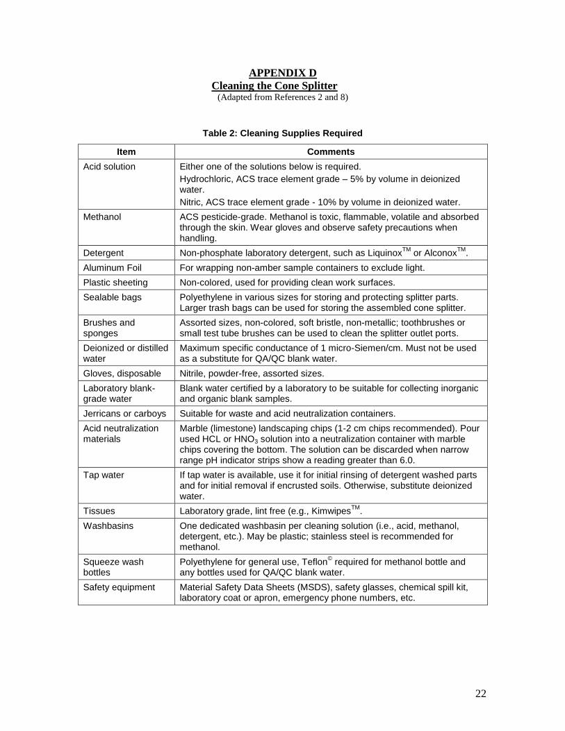
22
APPENDIX D
Cleaning the Cone Splitter (Adapted from References 2 and 8)
Table 2: Cleaning Supplies Required
Item Comments
Acid solution Either one of the solutions below is required. Hydrochloric, ACS trace element grade – 5% by volume in deionized water. Nitric, ACS trace element grade - 10% by volume in deionized water.
Methanol ACS pesticide-grade. Methanol is toxic, flammable, volatile and absorbed through the skin. Wear gloves and observe safety precautions when handling.
Detergent Non-phosphate laboratory detergent, such as LiquinoxTM or AlconoxTM. Aluminum Foil For wrapping non-amber sample containers to exclude light. Plastic sheeting Non-colored, used for providing clean work surfaces. Sealable bags Polyethylene in various sizes for storing and protecting splitter parts.
Larger trash bags can be used for storing the assembled cone splitter. Brushes and sponges
Assorted sizes, non-colored, soft bristle, non-metallic; toothbrushes or small test tube brushes can be used to clean the splitter outlet ports.
Deionized or distilled water
Maximum specific conductance of 1 micro-Siemen/cm. Must not be used as a substitute for QA/QC blank water.
Gloves, disposable Nitrile, powder-free, assorted sizes. Laboratory blank-grade water
Blank water certified by a laboratory to be suitable for collecting inorganic and organic blank samples.
Jerricans or carboys Suitable for waste and acid neutralization containers. Acid neutralization materials
Marble (limestone) landscaping chips (1-2 cm chips recommended). Pour used HCL or HNO3 solution into a neutralization container with marble chips covering the bottom. The solution can be discarded when narrow range pH indicator strips show a reading greater than 6.0.
Tap water If tap water is available, use it for initial rinsing of detergent washed parts and for initial removal if encrusted soils. Otherwise, substitute deionized water.
Tissues Laboratory grade, lint free (e.g., KimwipesTM. Washbasins One dedicated washbasin per cleaning solution (i.e., acid, methanol,
detergent, etc.). May be plastic; stainless steel is recommended for methanol.
Squeeze wash bottles
Polyethylene for general use, Teflon© required for methanol bottle and any bottles used for QA/QC blank water.
Safety equipment Material Safety Data Sheets (MSDS), safety glasses, chemical spill kit, laboratory coat or apron, emergency phone numbers, etc.
23
Introduction
For parts-per-billion (ppb) analyses, it is as important to carefully follow the cone splitter
cleaning protocol as to follow the sampling and splitting protocols. The cleaning protocol
below has been demonstrated to be adequate for trace metals and organics at the ppb
level. However, NPDES dioxin limits at SSFL require sampling at the parts-per-trillion
(ppt) level, which is uncharted territory for equipment cleaning protocols. For splitting
surface runoff samples in which COCs are closely associated with sediments, as at SSFL,
it has been shown that, at ppb levels, using a cone splitter produces more reliable
analytical results than alternative methods. For ppt levels, using a cone splitter appears to
be even more necessary. If equipment blanks should show that the cleaning protocol is
not adequate for ppt dioxin sampling, improvements will have to be sought.
If the cleaning requirements of dioxin ppt sampling are found to be beyond present
capabilities, it might be necessary to adopt statistical sampling procedures, similar to
those used for microbiological COCs such as E. coli, where single grab samples are never
assumed to be representative of the source.
The cone splitter must be cleaned each time before being used for splitting any new
composited samples. A new composited sample is one collected from a different site on
the same day or from the same site on a different day or the same site for a different
sampling event on the same day.
1. Before using a previously cleaned splitter for the first time, always start by
pouring 2 or 3 liters of deionized water through the splitter. Then collect an
equipment blank.
a) Collect the equipment blank by pouring 1-liter of laboratory blank-grade
water through the splitter and collect all of it using all of the outlet tubes.
Composite the entire collected equipment blank from the 10 outlet tubes into
one 1-liter laboratory container. This equipment blank container is capped,
sealed, labeled, and stored with the environmental samples.
b) If no COCs are detected in samples collected before the next cleaning, the
equipment blank does not need to be analyzed.
2. When splitting a series of samples collected from the same location and runoff
event, rinse the splitter between samples with at least 3-liters of deionized water.
3. When splitting samples collected from different sites on the same sampling day,
follow the Level 1 cleaning protocol (simpler than Level 2) between each split.
4. After all samples collected on the same day have been split, follow the Level 2
cleaning protocol (more thorough than Level 1) as soon as possible and store the
cone splitter under clean conditions (see below) until the next sampling day.
24
5. Differences between the Level 1 and Level 2 cleaning protocols are:
a) Level 2 requires complete disassembly of the cone splitter, whereas Level 1
does not.
b) Level 2 includes a detergent soak-and-scrubbing step, whereas no detergent is
used to clean the cone splitter in Level 1.
c) Level 2 includes a 30-minute acid soak, whereas a single acid rinse is used in
Level 1.
Level 1 Cleaning Protocol
Level 1 cleaning is used each time before the splitter is used for processing
samples collected from different sites on the same day.
The cone splitter need not be cleaned between processing successive multiple
samples collected from the same site.
The splitter must not be allowed to dry between Level 1 cleanings.
A Level 2 cleaning is required if the splitter has dried before being cleaned or was
used for splitting samples with known or suspected high concentrations of trace
elements.
Inspect the cone splitter. If it appears dirty, is suspected of being contaminated, or has
been allowed to dry, then it should be fully disassembled and cleaned using the Level 2
cleaning protocol described below. Otherwise, proceed with the Level 1 protocol.
Level 1 Cleaning Steps
1. Discard any used plastic bags from storing the cone splitter.
2. Rinse the splitter with at least 3-liters of deionized water.
3. Wearing disposable gloves, rinse with one liter of 5-percent by volume HCL to
remove any adsorbed metals.
a) The used acid/water solution should be placed in a neutralization container for
proper disposal.
4. Change gloves and rinse the cone splitter with at least three 1-liter aliquots of
deionized water.
5. If the next subsamples to be collected are to be analyzed for metals only and not
for organics (including dioxins), omit steps 6-9.
25
6. Using a Teflon® wash bottle, rinse splitter reservoir interior with 250-500 mL of
pesticide-grade methanol (methyl alcohol) to remove adsorbed organic
contaminants. Allow the liquid to drain through all the outlet tubes to waste
containers and disposed of properly.
a) Methanol is flammable, volatile, a skin and lung irritant and poisonous if
ingested. Read its attached Material Safety Data Sheet before using. Use
methanol sparingly in a well ventilated area, away from open flames or
sparks. When possible, performing this rinsing step in a hood is preferred.
b) A methanol rinsed cone splitter may not be used for obtaining subsamples to
be analyzed for total particulate carbon (TPC), particulate organic carbon
(POC) or dissolved and suspended organic carbon (DOC) analyses. Omit the
methanol rinse if these analyses are needed.
7. Dispose of gloves used in the methanol rinse.
8. Wearing new gloves, rinse methanol from the splitter with laboratory blank-grade
water from a wash bottle, paying special attention to the upper part of the
reservoir. Collect the rinse water through all outlet tubes to waste containers.
9. Follow the wash bottle rinse by pouring 3-liters of laboratory blank-grade water
through the splitter, collecting the rinse water through all outlet tubes to the same
waste containers.
10. The splitter is ready to process a new composited sample from another site or
sampling event.
11. When all samples collected on the same day have been processed, clean the cone
splitter using the Level 2 protocol prior to storage.
Level 2 Cleaning Protocol
Level 2 cleaning is used:
Before using a new splitter the first time.
After all samples from a given sampling day have been processed.
Any time the splitter has been allowed to dry before being cleaned.
Any time the splitter has been used with samples with known or suspected high
concentrations of trace elements.
26
Level 2 Cleaning Steps
1. Prepare a contaminant-free space for working.
a) Gather the cleaning supplies, the equipment to be cleaned and plastic bags
with which to double-bag and seal bag the cleaned equipment. Check Table 2
for the cleaning supplies needed.
b) Place clean plastic sheeting over the work surface.
2. Put on disposable, powder-free nitrile gloves, a laboratory coat or apron, and
safety glasses.
3. Clean the items used to clean the equipment.
a) Fill superficially clean washbasins with the non-phosphate detergent solution.
Put wash bottles, scrub brushes, and other small items used for cleaning into a
washbasin. Soak for 30 minutes.
b) Scrub interior and exterior sides of basins with soft scrub brushes. Fill wash
bottles with a soapy solution and shake vigorously.
c) Rinse all items thoroughly with tap water to remove detergent residue. No
detergent bubbles should appear when fresh tap water is agitated in the basin
or wash bottle.
d) Rinse washbasins with deionized water.
e) Pour 5-percent HCl (or 10-percent HNO3) solution into washbasins,
standpipes, and wash bottles. Soak for 30 minutes.
f) Discard used acid solution into a neutralization container containing a bottom
layer of marble chips.
g) Rinse washbasins and wash bottles with deionized water.
4. Unwrap the equipment to be cleaned and discard the storage bags. Change gloves.
5. Fully disassemble the cone splitter, carefully safeguarding all of the small parts.
6. Soak the splitter parts and Teflon® outlet tubing for 30 minutes in a 2-percent
(for hard water) or less solution of phosphate-free laboratory detergent. Use a
cleaned basin for soaking.
7. Wearing disposable nitrile gloves, scrub all surfaces with a nonmetallic brush.
a) A clean tooth brush or small soft-bristle test tube brush can be used to clean
the small splitter parts.
27
b) Pay particular attention to removing foreign material from threaded and hard-
to-access parts.
8. Rinse all splitter parts thoroughly with deionized water.
9. Soak non-metal parts for 30 minutes in a 5-percent, by volume, solution of HCl.
Carefully swirl the acid solution several times during the 30-minutes soak to
enhance desorption of trace elements not removed during the detergent washing
process.
a) Discard used acid solution into a neutralization container.
10. Change gloves and rinse all splitter parts three times with 1-liter aliquots of
deionized water.
a) Allow all parts to air-dry.
b) Discard the rinse water in a neutralization container.
11. Reassemble the cone splitter and double-bag and seal it in plastic bags for storage.
Storage of Level 2-Cleaned Cone Splitter
1. Before reassembling and storing, cone splitters always should be visually
inspected for damage especially the cone splitting chamber. Units that show
damage or wear should be recalibrated to check their serviceability. Check
discharge tubing frequently for proper length and cleanliness. Replace tubes as
conditions warrant.
2. Allow the cone splitter to dry. If the splitter will be used again within 3 days, it
need not be dry when stored providing it is kept chilled to prevent bacterial
growth.
3. Double-bag the cone splitter into new clean plastic bags. Seal each bag separately.
28
APPENDIX E
Inherent Variability in Parts-Per-Billion Analyses of Low Solubility Pollutants
This appendix contains a very brief description of certain statistical and technical
limitations inherent in the sampling and chemical analysis of parts-per-billion (ppb)
concentrations of low solubility pollutants such as dioxins and certain metals. Although
the following discussion contains information about dioxins, the same issues apply to any
low solubility pollutant that must be analyzed at ppb concentrations.
Analytical Variability
Analytical limitations introduce a significant and unavoidable degree of variability in the
reported results. As a current example, the expected variability of repeat measurements
on a single sample containing 2,3,7,8-TCDD at 3x10⁻⁸
mg/L (30 pg/L)2 seems to be
between ±25% to ±10% (measured as %- relative standard deviation, RSD), depending
on the amount of interfering substances in the sample.3 This is a laboratory-induced
variability that must be added to the field sampling variability, which has been reported
to be as large as ±30% for particulate sample types.4
No data could be found for the expected variability at lower concentrations comparable to
SSFL NPDES limits. However, as sample concentration decreases for the same analytical
method, precision inevitably decreases and expected variability increases. Achieving
acceptable analytical results for SSFL NPDES samples requires extreme rigor and
consistency in all the separate analytical steps of sample extraction, concentration,
calibration, and instrumental operation.
The two main reasons for this variability in dioxin measurements are:
The very low water solubility of dioxins in general.
o The water solubility of 2,3,7,8-TCDD (TCDD) is 19x10-6 mg/L. In
general, all of the dioxin congeners containing 4 or more chlorine atoms
have similar low water solubilities.
o Low solubility causes dioxins in environmental water samples to be
largely associated with sediments. Although the TCDD solubility of
19x10-6 mg/L is greater than the EPA drinking water MCL for TCDD
(3x10⁻⁸ mg/L), it is small enough to result in most water-borne dioxin
molecules being bound to sediments.
2 30 pg/L (30x10
-12 g/L) is the EPA drinking water standard and is a common requirement for analytical
samples. It is about 1000-times larger than the SSFL NPDES limits.
3 This value is estimated from information in the EPA Method 1613 document, some reported values from
the literature, and a telephone discussion with the Chief Analyst at Pace Laboratories.
4 “Femtograms or phantomgrams? An analytical view of the organochlorine issue”, Ray Clement, Ontario
Ministry of Environment and Energy, Laboratory Services Branch, Chemical Institute of Canada, 1997,
http://www.thefreelibrary.com/Femtograms+or+phantomgrams%3F+an+analytical+view+of+the+organochlorine...-a020029520.
29
o Because of suspended sediment (TSS) inhomogenieties, TSS samples
from the same source tend to have higher variability in their measured
concentrations than would be the case for dissolved analytes. Standard
Methods5 reports an analytical precision (standard deviation) of 21.20
mg/L for TSS analyses of water samples containing 293 mg/L of a TSS
standard. This is equivalent to an RSD of ±7.2%.
o When dioxins are distributed between dissolved and solid phases, extra
analytical processing steps are required for filtration, drying the solids,
different extraction procedures to separate the analyte from the solid and
from water, and recombining the extracted analytes into a single sample;
all before concentrating the sample to increase analytical sensitivity.
The necessity to quantitatively measure the analyte at a very low concentration.
o This requires that at least 1 liter of collected sample be extracted and
concentrated. At least 5% of the concentrate must be injected into the
GC/MS instrument to assure that there is enough dioxin present in the
injected sample to obtain the required sensitivity. To analyze for 30 pg/L
of dioxin, the lab calibrates with 10 pg/L spikes and adjusts instruments
for a 1 pg/L detection limit. Measurement errors can be introduced in
every step. The laboratory reporting requirements listed in Appendix A
illustrate the many potential sources of error inherent in part-per-billion
laboratory analyses.
Sampling Variability
Sampling procedures introduce additional measurement variability, which must be added
to the analytical variability. Dioxins in stormwater tend to concentrate on suspended
solids carried in the flow and it is essentially impossible to collect sequential samples
from the same source in which the solids and, consequently, the dioxins are equally
distributed.
The greatest source of stormwater sampling variability comes from fluctuations in the
suspended solids content of different samples collected at the same time from the same
source. Replicate samples collected sequentially, whose percent solids levels vary
significantly between replicates, will have poor agreement in dioxin concentrations
between replicates. The percent standard deviation of dioxin concentrations for samples
of equal sediment concentrations depends on the sample size, increasing as sample size
decreases.
Thermal mixing assures that the dissolved portion of dioxin is uniformly distributed, but
the sediment-sorbed portion will be spatially variable for several reasons:
5 Single-laboratory analyses of 77 samples containing a known TSS of 293 mg/L. “Standard Methods for
the Examination of Water and Wastewater”, 19th
edition, 1995, A.D. Eaton, et al., Eds., American Public
Health Assoc., Washington, DC.
30
Particles with different masses are transported in flowing water at different
velocities and settle vertically at different rates.
Different sediment particles can have different surface areas because they may be
of different sizes, have different porosities, and have different weathering
histories.
Dioxins will sorb differently to particles of different chemical origins. In general,
for equal weights, organic sediments will contain more dioxin than inorganic
sediments.
Particles from different sources may have different densities and will not be
homogeneously distributed throughout the sample volume.
Even if a single large sample were theoretically split precisely into smaller replicates,
each containing exactly the same sediment concentrations, there still would be variability
in their dioxin concentrations because different sediment particles will contain different
numbers of sorbed dioxin molecules. The smallest dioxin variability would only be
achieved if all replicates contained identical particle size distributions, identical particle
density distributions, identical particle surface area distribution, and identical
distributions of organic and mineral sediments, a presently impossible goal.
At the present time, the cone-splitter appears to be one of the best methods for splitting
stormwater samples. It is simple to use and has been shown to more reliably split aqueous
samples with significant solids or sediment content than the more commonly used tilt and
pour method, which has poor repeatability and yields split samples with widely varying
solids concentrations and particle size distributions.
�
Alexander Fischl
From: Blair, Lori N [[email protected]]Sent: Tuesday, October 19, 2010 2:35 PMTo: Alexander Fischl; Dixie HambrickCc: Benjamin Stewart; Shelby Valenzuela; Eric VanderVelde; Jim Hickle; Fuentes, Gilbert LSubject: FW: Confirmation For Boeing ISRA areas B1-1A, -1B, -1C; CTL1-Band IEL-1
�������������������
�������������������� �������������������������������������������������������� !�!� � "�#$�����%�����&���'��� �����(������)��������*��%������+,(-������%�.�-��.�%��.��/���&�.%����+0&.����1�������1���������������������������������������������������1������������ !�!����)����������������������)�����������2������������)����1����)����!!�������1�������������������
�����������3�������4�����1��)��+���������#���������4����5'#30,6�&���-�������(��������7����8��������������%����9 !�7����:�1�,������,����� !!�&���-���������-��!!�9�#1����5 �96�;<"."<;!���������������������������===�>%�����&���'>�?���������������������=��!@�:@ !�!��!�!!�-$�===�All - This email serves to document agreements reached during a teleconference held on Monday October 11, 2010 with RWQCB staff regarding excavation extent and confirmation sampling results for five ISRA Areas in Outfall 009. Attending the teleconference were: Cassandra Owens, Peter Raftery, and Mahzar Ali (RWQCB), Buck King (DTSC), Lori Blair (Boeing), Bob Weiner (Storm Water Expert Panel), and Dixie Hambrick, Alex Fischl, and Ben Stewart (MWH). Pre-excavation and final confirmation sampling maps and data tables for the five ISRA Areas, which included RWQCB split confirmation samples, were transmitted via email to the agencies by Alex Fischl on Tuesday October 5, 2010 to allow agencies time to review the documents. Confirmation sampling data was reviewed for 5 of the Outfall 009 ISRA Areas on Boeing property, including B1-1A, B1-1B, B1-1C, CTLI-1B, and IEL-2. The ISRA Areas reviewed, a summary of the results, and agreements reached during the October 11, 2010 teleconference are described below (ISRA COCs indicated in parentheses). Completed areas • B1-1A (copper, lead, dioxins): Excavation performed as planned, with bedrock encountered at
depth in southwestern and northeastern portion. Seven MWH confirmation samples and one
agency split sample collected, all data received. All results less than soil remediation goals. Agencies concurred during call that excavation activities at this location are complete.
• B1-1B (dioxins): Excavation performed as planned, with bedrock encountered at depth in the
southwest portion. Twenty two MWH confirmation samples and one agency split sample collected, all data received. All results less than soil remediation goals. Agencies concurred during call that excavation activities at this location are complete.
• B1-1C (dioxins): Excavation performed as planned. Two MWH confirmation samples and one
agency split sample collected, all data received. All results less than soil remediation goals. Agencies concurred during call that excavation activities at this location are complete.
• CTLI-1B (copper, lead, dioxins): Excavation performed as planned, with bedrock encountered
at depth in the southern and northern portions, and in 2 locations along the eastern boundary. Four MWH confirmation samples and two agency split sample collected, all data received. All results less than soil remediation goals, with the exception of one MWH confirmation sample that had a result of 35 mg/kg for lead compared to the soil remediation goal of 34 mg/kg. However, because this result is very close to the soil remediation goal and the RWQCB split sample result was below the soil remediation goal, the Agencies agreed to leave the sample in place but requested this sample be documented in the summary report. Agencies concurred during call that excavation activities at this location are complete.
• IEL-1 (copper, mercury): Excavation performed as planned, with bedrock encountered at
depth. Trenches were present through the bedrock that contained active utilities and were backfilled with hard, compacted material. Two MWH confirmation samples and one agency split sample collected, all data received. All results less than soil remediation goals, with the exception of one MWH confirmation sample that had a result of 34 mg/kg for copper, compared to the soil remediation goal of 29 mg/kg. However, because this sample was collected within the hard backfill covering active utilities, the sample would be covered with 6” to 1 foot of clean backfill, the result is very close to the soil remediation goal, and the RWQCB split sample result was below the soil remediation goal, the Agencies agreed to leave the sample in place but requested this sample be documented in the summary report. Agencies concurred during call that excavation activities at this location are complete.
Our team appreciates the RWQCB and DTSC timely review of this information. We will not begin any recontouring or regrading activities until authorized by the RWQCB. Sincerely, Lori Blair ��
1
Margaret Milman-Barris
From: Cassandra Owens [[email protected]]Sent: Wednesday, October 27, 2010 10:57 AMTo: Lori N Blair; 'Buck King'; Mazhar Ali; Peter RafteryCc: [email protected]; James A. (MSFC-AS10) Elliott; Alexander Fischl; Benjamin
Stewart; Dixie Hambrick; Margaret Milman-Barris; [email protected]; [email protected]
Subject: Re: Confirmation For Boeing ISRA areas B1-1D and CTL-1A
Regional Board staff and DTSC staff agree that the attached email accurately documents the decisions made during the October 20, 2010 conference call.
Thanks Cassandra
Cassandra D. Owens Unit Chief, Industrial Permitting Unit (NPDES) Los Angeles Regional Water Quality Control Board 320 West 4th Street, Suite 200 Los Angeles, CA 90013 Phone (213) 576-6750 [email protected]
>>> "Blair, Lori N" <[email protected]> 10/21/2010 1:02 PM >>> All -
This email serves to document agreements reached during a teleconference held on Wednesday October 20, 2010 with RWQCB staff regarding excavation extent and confirmation sampling results for two ISRA Areas (B1-1D and CTLI-1A) in Outfall 009. Attending the teleconference were:Cassandra Owens and Mahzar Ali (RWQCB), Buck King (DTSC), Donna Holland (NASA), Lori Blair (Boeing), Bob Weiner (Storm Water Expert Panel), Randy Dean (CH2M HILL), and Alex Fischl (MWH). Pre-excavation and final confirmation sampling maps and data tables for the two ISRA areas, which included RWQCB split confirmation samples, were transmitted via email to the agencies by Alex Fischl on Wednesday October 6, 2010 (B1-1D) and Wednesday October 20, 2010 (CTLI-1A) to allow agencies time to review the documents.
Confirmation sampling data was reviewed for 2 of the Outfall 009 ISRA Areas on Boeing property, including B1-1D and CTLI-1A. B1-1A, B1-1B, B1-1C, CTLI-1B, and IEL-1 confirmation data were reviewed with RWQCB and DTSC staff during a teleconference held on October 11, 2010 and all were in agreement that excavations at these areas were complete. This agreement is documented in an email to Boeing from RWQCB staff on October 19, 2010. B1-2, AP/STP-1A, AP/STP-1D, and AP/STP-1F confirmation data was not reviewed since final data were not yet available. Future calls will be conducted to review this data.
The ISRA Areas reviewed, a summary of the results, and agreements reached during the October 20, 2010 teleconference are described below (ISRA COCs indicated in parentheses).
Completed areas
� B1-1D (mercury, dioxins): Additional excavation required by agency to address ten initial confirmation samples with results above soil remediation goals (B1ET0300 through B1ET0304,
2
B1ET0306, B1ET0307, B1ET0319, B1ET0320, and B1ET0325). Additional excavation was performed in 4 areas and bedrock was encountered at depth. No additional confirmation samples were collected. RWQCB staff observed completed additional excavation areas on October 18, 2010 and agreed no additional confirmation samples were needed. Twenty-seven MWH confirmation samples and four agency split sample collected, all data received. Final, in place, MWH data and RWQCB split data less than soil remediation goals. Agencies concurred during call that excavation activities at this location are complete.
� CTLI-1A (copper, lead, dioxins): Additional excavation required by agency to address 4 initial confirmation samples with results above soil remediation goals (LFET0101, LFET0106, LFET0110, and LFET0111). Additional excavation was performed in 3 areas and bedrock was encountered at depth. One additional sidewall confirmation sample (MWH sample and RWQCB split sample) was collected from one of the additional excavation areas. Nineteen MWH confirmation samples and three agency split sample collected, all data received. All results less than soil remediation goals. Agencies concurred during call that excavation activities at this location are complete.
Our team appreciates the RWQCB and DTSC timely review of this information. We will not begin any recontouring or regrading activities until authorized by the RWQCB.
Sincerely,Lori Blair ��
1
Margaret Milman-Barris
From: Cassandra Owens [[email protected]]Sent: Wednesday, November 24, 2010 9:59 AMTo: Lori N Blair; 'Buck King'; Mazhar Ali; Peter RafteryCc: [email protected]; James A. (MSFC-AS10) Elliott; Alexander Fischl; Benjamin
Stewart; Dixie Hambrick; Margaret Milman-Barris; [email protected]; [email protected]
Subject: Re: Confirmation For Boeing ISRA areas AP/STP 1D and 1F
This email accurately documents the decisions made with Regional Board and DTSC staff concurrence during the Monday, November 22, 2010, conference call.
Cassandra D. Owens Unit Chief, Industrial Permitting Unit (NPDES) Los Angeles Regional Water Quality Control Board 320 West 4th Street, Suite 200 Los Angeles, CA 90013 Phone (213) 576-6750 [email protected]
>>> "Blair, Lori N" <[email protected]> 11/24/2010 8:48 AM >>> All -
This email serves to document agreement reached during a teleconference held on Monday November 22, 2010 with RWQCB staff regarding excavation extent and confirmation sampling results for ISRA Areas AP/STP-1D and AP/STP-1F in Outfall 009 (NASA property). Attending the teleconference were: Cassandra Owens and Mazhar Ali (RWQCB), Buck King (DTSC), Lori Blair (Boeing), Allen Elliott (NASA), Randy Dean (CH2M HILL), and Alex Fischl and Ben Stewart (MWH). Final confirmation sampling maps and data tables for the ISRA area, which included RWQCB split confirmation samples, were transmitted via email to the agencies by Alex Fischl on Monday November 22, 2010 shortly after the call.
Confirmation sampling data was reviewed for ISRA areas AP/STP-1D and AP/STP-1F in Outfall 009 on NASA property. A summary of the results for AP/STP-1D and AP/STP-1F and the agreement reached during the November 22, 2010 teleconference are described below (ISRA COCs indicated in parentheses).
Completed areas
� AP/STP-1D (dioxins): Additional excavation required by agency to address two initial floor confirmation samples with results above soil remediation goals (APET0402 and APET0408). Additional excavation was performed in two areas. Two additional floor confirmation samples were collected, RWQCB collected one split sample. Twelve MWH confirmation samples and three agency split samples collected, all data received. All in place samples contain results less than soil remediation goals. Agencies concurred during call that excavation activities at this location are complete.

2
� AP/STP-1F (dioxins): Additional excavation required by agency to address one initial floor confirmation samples with results above soil remediation goals (APET0603). Additional excavation was performed in one area. One additional floor confirmation sample was collected, RWQCB collected one split sample. Eight MWH confirmation samples and four agency split samples collected, all data received. All in place samples contain results less than soil remediation goals. Agencies concurred during call that excavation activities at this location are complete.
� Previously, ISRA areas B1-1A, B1-1B, B1-1C, CTLI-1B, and IEL-1 confirmation data was reviewed with RWQCB and DTSC staff during a teleconference held on October 11, 2010 and all were in agreement that excavations at these areas were complete. ISRA areas B1-1D and CTLI-1A confirmation data were reviewed with RWQCB and DTSC staff during a teleconference held on October 20, 2010 and all were in agreement that excavations at these areas were complete. ISRA area AP/STP-1A confirmation data were reviewed with RWQCB and DTSC staff during a teleconference held on November 3, 2010 and all were in agreement that excavation at this area was complete. �
Our team appreciates the RWQCB and DTSC timely review of this information. Please reply to this email concurring with the summary above.
Lori Blair �

1
Margaret Milman-Barris
From: Alexander FischlSent: Friday, December 10, 2010 12:04 PMTo: Margaret Milman-BarrisSubject: FW: Confirmation For Boeing ISRA areas: Partial B1-2 area -pending discussion with
Buck King and concurrence email from CassandraOwens
Importance: High
RWQCB and DTSC confirmations included below.
Alex Fischl MWH ! Walnut Creek, CA Office office: 925!627!4627 cell: 925!997!7384
From: Blair, Lori N [mailto:[email protected]]Sent: Wednesday, December 08, 2010 8:15 AM To: Alexander Fischl; Shelby Valenzuela; Dixie Hambrick; Lenox, Arthur J Cc: 'Jim Hickle'; Fuentes, Gilbert L Subject: FW: Confirmation For Boeing ISRA areas: Partial B1-2 area -pending discussion with Buck King and concurrence email from CassandraOwens Importance: High
So – we are good to go. Shelby – can you update me on the status of the trench logging and surveying? Are we ready to start backfilling tomorrow?? I’d like to provide status at the 10am call tomorrow.
Also – can you please be sure to mark out for Jim where we are authorized to move forward??
Thanks!
Lori
From: Cassandra Owens [mailto:[email protected]]Sent: Tuesday, December 07, 2010 1:38 PM To: Blair, Lori N; Buck King; Mazhar Ali; Peter Raftery Subject: RE: Confirmation For Boeing ISRA areas: Partial B1-2 area -pending discussion with Buck King and concurrence email from CassandraOwens

2
Regional Board staff participated in the conference call and we agree that the attached email accurately documents the discussion that occurred. This email provides affirmation from the Regional Board staff that excavation in the area identified with the dashed yellow outline is complete and approval to proceed with tench logging and re-contouring in the area.
Cassandra D. Owens Unit Chief, Industrial Permitting Unit (NPDES) Los Angeles Regional Water Quality Control Board 320 West 4th Street, Suite 200 Los Angeles, CA 90013 Phone (213) 576-6750 [email protected]
>>> Buck King <[email protected]> 12/7/2010 10:45 AM >>> Cassandra Owens and Lori Blair,
I have reviewed the email message below and the attached figure and table describing the B1-2 area and concur with the opinion that excavation is complete within the area identified by dashed yellow outline on attached figure 1. Please use this email as documentation of DTSC review and approval of this project issue.
Buck King, PG, CHG Senior Engineering Geologist (510) 540-3955 Fax (510) 540-3937 [email protected]
>>> "Blair, Lori N" <[email protected]> 12/7/2010 10:02 AM >>> All -
This email serves to document agreement reached during a teleconference held on Tuesday December 7, 2010 with RWQCB staff regarding excavation extent and confirmation sampling results for ISRA area B1-2 in Outfall 009 (Boeing property). Attending the teleconference were: Cassandra Owens, Peter Raftery, and Mazhar Ali (RWQCB), Lori Blair and Art Lenox (Boeing), Jon Jones (Storm Water Expert Panel), and Alex Fischl (MWH). The confirmation sampling map and data table for the ISRA area, which include RWQCB split confirmation samples, are an attachment to this email.
Although some confirmation sample data is still pending, there are portions of B1-2 that have confirmation samples with results below SRGs. Boeing requested this meeting with agencies to review the data received to date and obtain agreement from agencies that excavation is complete in portions of the B1-2 ISRA area and restoration activities can begin. The areas outlined in yellow dashed lines on the attached figure contain confirmation sample results below SRGs, with the exception of 4 samples. Three of these samples exceeded the SRG for dioxins (B1ET0517, B1ET0521, and B1ET0635), however, our chemist reviewed the data and confirmed that during validation these results will decrease to below the SRG. The other sample with results above SRGs, B1ET0622, was a sidewall sample from soil left in place due to the presence of tar plant. This sample has been removed and another confirmation sample was collected. However, due to the presence of the tar plant (a protected species), the project biologist recommended not to remove any additional soil at this location.
Following the discussion above, RWQCB concurred during call that excavation activities were complete within the areas within the yellow dashed boundaries on the attached figure. Our team appreciates the RWQCB and DTSC timely review

3
of this information. Please reply to this email concurring with the summary above. We will not begin any recontouring or regrading activities until authorized by the RWQCB.
Sincerely,
Lori Blair
1
Margaret Milman-Barris
From: Shelby ValenzuelaSent: Monday, January 10, 2011 2:37 PMTo: Margaret Milman-BarrisSubject: FW: Final Confirmation sample results for B1-2 - Peter orMahzar - please provide a
confirmatory email in response
FYI
From: Blair, Lori N [mailto:[email protected]]Sent: Monday, January 10, 2011 2:34 PM To: Alexander Fischl; Dixie Hambrick; [email protected]; Shelby Valenzuela; Benjamin Stewart Subject: FW: Final Confirmation sample results for B1-2 - Peter orMahzar - please provide a confirmatory email in response Okay – we are done!!!! I’ll send out a more formal email to everyone here in a little bit. But for now – Shelby – can you let me know if we started surveying today? I think we should have been able to start. Ben – I think tomorrow Alex S. will be on site and you all will figure out the temporary BMP install and keep moving on the plan for the final. Let me know okay? Tomorrow I think I will be touring around a lot – so if you get voice mail on my cell – 805!258!8150 – I’ll call you back as soon as I can. Thanks so much!! Lori
From: Peter Raftery [mailto:[email protected]]Sent: Monday, January 10, 2011 2:27 PM To: Blair, Lori N Cc: Buck King; Arthur Heath; Cassandra Owens; David Hung; Mazhar Ali; Su Han Subject: Re: Final Confirmation sample results for B1-2 - Peter orMahzar - please provide a confirmatory email in response Lori:
Regional Board staff agree that ISRA actions are complete for ISRA site B1-2. Please contact me if you have any questions.
Regards,
Peter J. Raftery, PG, CHG Engineering Geologist Los Angeles Regional Water Quality Control Board 320 W. 4th Street Los Angeles, Ca 90013 ph 213.576.6724 fx 213.576.6717
2
Safeguarding the Environment - it's Right, it's Smart, it's our Future.
-------------------------------------------------------------------------------------------------------------------------------------------------------------------------------------------------------- >>> "Blair, Lori N" <[email protected]> 1/6/2011 4:16 PM >>> All !
This email serves to document the teleconference held on Wednesday January 5, 2011 with
RWQCB staff regarding excavation extent and confirmation sampling results for ISRA area B1!2
in Outfall 009 (Boeing property). Attending the teleconference were: Mazhar Ali and Peter
Raftery (RWQCB), Buck King (DTSC), Paul Costa and Lori Blair (Boeing), Ashley Boudreaux and
Allen Elliott (NASA), Randy Dean (CH2M HILL), Robert Weiner and Jon Jones (Storm Water
Expert Panel), and Alex Fischl, Dixie Hambrick, Shelby Valenzuela, and Ben Stewart (MWH).
Confirmation sampling maps and data tables for the ISRA area, which included RWQCB split
confirmation samples, were transmitted via email to the agencies by Alex Fischl on Tuesday
December 21, 2010. Since this transmittal, results for the final 2 samples were received
and the final in!place and excavated confirmation sampling map and data table for the ISRA
area were submitted shortly before the call.
Available confirmation sampling data was reviewed for ISRA areas B1!2 during a
teleconference held on December 7, 2010. During the teleconference, RWQCB staff concurred
that excavation in select areas were complete and restoration activities could begin. DTSC
staff concurred in an email dated December 7, 2010.
Since the December 7, 2010 teleconference, additional excavation has been performed and
additional confirmation sample results have been received. Currently, all in!place
confirmation samples results are below SRGs with the following exceptions:
- Preliminary dioxin results for five samples exceed the SRG, however, the project
chemist reviewed the data and confirmed dioxin results will drop below the SRG during
validation. These five samples are circled in green on the attached figure.
- Results for four samples exceed the SRG for select metals and/or dioxins, however,
these samples are located beneath oak trees and the project arborist and biologist
recommend no additional excavation at these locations (correspondences from arborist
and biologist attached). These four samples are circled in purple on the attached
figure.
- The lead result for one sample exceeds the SRG, however, this sample is a sidewall
sample located along the entrance road and no additional excavation can occur at this
location without compromising the road.
Results for all final in!place samples, including those with results exceeding the SRGs,
will be incorporated into the RFI program.
Following the discussion above, agencies concurred during call that excavation activities at
B1!2 are complete. Our team appreciates the RWQCB and DTSC timely review of this
information. Please reply to this email concurring with the summary above. We will not
begin any recontouring or regrading activities until authorized by the RWQCB.
Sincerely,
Lori Blair