Embed Size (px)
Citation preview

SANDIA REPORT SAND2013-9106 Unlimited Release Printed November 2013
Scaling Considerations for a Multi-Megawatt Class Supercritical CO2 Brayton Cycle and Commercialization Darryn D. Fleming, Thomas M. Conboy, James J. Pasch, Gary A. Rochau, Robert L. Fuller, Thomas V. Holschuh, Steve A. Wright Prepared by Sandia National Laboratories Albuquerque, New Mexico 87185 and Livermore, California 94550
Sandia National Laboratories is a multi-program laboratory managed and operated by Sandia Corporation, a wholly owned subsidiary of Lockheed Martin Corporation, for the U.S. Department of Energy's National Nuclear Security Administration under contract DE-AC04-94AL85000. Approved for public release; further dissemination unlimited.

2
Issued by Sandia National Laboratories, operated for the United States Department of Energy by Sandia Corporation. NOTICE: This report was prepared as an account of work sponsored by an agency of the United States Government. Neither the United States Government, nor any agency thereof, nor any of their employees, nor any of their contractors, subcontractors, or their employees, make any warranty, express or implied, or assume any legal liability or responsibility for the accuracy, completeness, or usefulness of any information, apparatus, product, or process disclosed, or represent that its use would not infringe privately owned rights. Reference herein to any specific commercial product, process, or service by trade name, trademark, manufacturer, or otherwise, does not necessarily constitute or imply its endorsement, recommendation, or favoring by the United States Government, any agency thereof, or any of their contractors or subcontractors. The views and opinions expressed herein do not necessarily state or reflect those of the United States Government, any agency thereof, or any of their contractors. Printed in the United States of America. This report has been reproduced directly from the best available copy. Available to DOE and DOE contractors from U.S. Department of Energy Office of Scientific and Technical Information P.O. Box 62 Oak Ridge, TN 37831 Telephone: (865) 576-8401 Facsimile: (865) 576-5728 E-Mail: [email protected] Online ordering: http://www.osti.gov/bridge Available to the public from U.S. Department of Commerce National Technical Information Service 5285 Port Royal Rd. Springfield, VA 22161 Telephone: (800) 553-6847 Facsimile: (703) 605-6900 E-Mail: [email protected] Online order: http://www.ntis.gov/help/ordermethods.asp?loc=7-4-0#online

3
SAND2013-9106 Unlimited Release
Printed November 2013
Scaling Considerations for a Multi-Megawatt Class
Supercritical CO2 Brayton Cycle and Commercialization
Darryn D. Fleming, Thomas V. Holschuh, Thomas M. Conboy, James J. Pasch, Steve A. Wright, Gary A. Rochau
Advanced Nuclear Concepts Sandia National Laboratories
P.O. Box 5800 Albuquerque, New Mexico 87185
Robert L. Fuller
Barber-Nichols, Inc. 6325 W 55th Ave. Arvada, CO 80002
Abstract Small-scale supercritical CO2 demonstration loops are successful at identifying the important technical issues that one must face in order to scale up to larger power levels. The Sandia National Laboratories supercritical CO2 Brayton cycle test loops are identifying technical needs to scale the technology to commercial power levels such as 10 MWe. The small size of the Sandia 1 MWth loop has demonstration of the split flow loop efficiency and effectiveness of the Printed Circuit Heat Exchangers (PCHXs) leading to the design of a fully recuperated, split flow, supercritical CO2 Brayton cycle demonstration system. However, there were many problems that were encountered, such as high rotational speeds in the units. Additionally, the turbomachinery in the test loops need to identify issues concerning the bearings, seals, thermal boundaries, and motor controller problems in order to be proved a reliable power source in the 300 kWe range. Although these issues were anticipated in smaller demonstration units, commercially scaled hardware would eliminate these problems caused by high rotational speeds at small scale. The economic viability and development of the future scalable 10 MWe solely depends on the interest of DOE and private industry. The Intellectual Property collected by Sandia proves that the ~10 MWe supercritical CO2 power conversion loop to be very beneficial when coupled to a 20 MWth heat source (either solar, geothermal, fossil, or nuclear). This paper will identify a

4
commercialization plan, as well as, a roadmap from the simple 1 MWth supercritical CO2 development loop to a power producing 10 MWe supercritical CO2 Brayton loop.

5
THIS PAGE INTENTIONALLY LEFT BLANK

6
CONTENTS
Nomenclature .................................................................................................................................. 8
Executive Summary ...................................................................................................................... 10
1. Introduction ........................................................................................................................... 12
2. Experimental Scaling of S-CO2 Brayton Cycles .................................................................. 13
3. Turbomachinery Considerations ........................................................................................... 13
4. S-CO2 Brayton Cycle Parameters for Large Scale Systems ................................................. 15
5. Turbomachinery Scaling Considerations .............................................................................. 17 5.1. Shaft Size and Turbomachinery Size .............................................................................. 17 5.2. Shaft Configuration, Number of Shafts, Gear Box ......................................................... 20 5.3. Bearings (Journal, Thrust) .............................................................................................. 20 5.4. Seals ................................................................................................................................ 21 5.5. Windage Losses .............................................................................................................. 22 5.6. Gear Box Speed Reduction ............................................................................................. 22 5.7. Motor/Generator and Control Electronics ...................................................................... 23 5.8. Purge Gas Management .................................................................................................. 23 5.9. Heat Exchangers ............................................................................................................. 23
6. Road Map for 10 MWe S-CO2 Brayton Cycle Technology .................................................. 24 6.1. Rough Cost Estimates for 10 MWe S-CO2 Brayton Cycle System ................................ 24
7. Timeline for S-CO2 Brayton Cycle Program ........................................................................ 26
8. Conclusions ........................................................................................................................... 27
9. Future Work .......................................................................................................................... 28
Distribution ................................................................................................................................... 29

7
FIGURES Figure 1: Cycle Efficiency as a function of temperature for types of power conversion ............. 12 Figure 2: Component and Technology options for S-CO2 systems .............................................. 14 Figure 3: Schematic drawing of a re-compression or split-flow Brayton cycle ........................... 15 Figure 4: Shaft speed and turbine diameter required by turbomachinery ..................................... 19 Figure 5: Gas-Foil Bearings used in the 1 MWth S-CO2 Brayton Cycle at Sandia. ...................... 21 Figure 6: Printed Circuit Heat Exchanger from Heatric ............................................................... 24
TABLES
Table 1: Summary of cycle conditions for a re-compression S-CO2 Brayton cycle. ................... 16 Table 2: Estimates for Purchase of S-CO2 Brayton Cycle System Components .......................... 25 Table 3: Budget Considerations for S-CO2 Brayton Cycle Program ............................................ 25
8
NOMENCLATURE
CO2 Carbon Dioxide DOE Department of Energy H2 Hydrogen Gas kWe kilowatt-electric MWe Megawatt-Electric MWth Megawatt-Thermal Na Sodium PCHX Printed Circuit Heat Exchanger S-CO2 Supercritical Carbon Dioxide TAC Turbo-Alternator-Compressor TM Turbomachinery

9
THIS PAGE INTENTIONALLY LEFT BLANK

10
EXECUTIVE SUMMARY
Power conversion systems are constantly being improved in order to respond to increasing energy demands in the world. Efficiency in these systems is the key to producing the most power for the smallest investment. Traditionally, a Rankine cycle, operated with steam, utilizes a turbine connected to a generator to produce electricity. The Rankine cycle has been hugely popular since its inception as a steam engine in the 19th century. A Brayton cycle usually operates using a gas at higher temperatures, which improves the overall efficiency as compared to a traditional Rankine cycle. In addition, efficiency in a Brayton cycle can be furthered improved with the use of supercritical fluid, such as water or carbon dioxide, to avoid phase changes as well as increasing the temperature difference within the cycle.
The research into advanced power conversion systems focuses on this area: a supercritical fluid in a Brayton cycle (both open and closed cycles). Supercritical water was an early candidate due to the extensive operating knowledge of water gained from hundreds of years of experience with a Rankine cycle. However, it was found that supercritical water is extremely corrosive, making it inappropriate for use in turbines and compressors in a Brayton cycle. In order to avoid this corrosiveness, carbon dioxide can be employed as a supercritical fluid for use in the power conversion systems. In fact, supercritical carbon dioxide (S-CO2) is highly suited for use in this capability. Research into this area is being led by the Advanced Nuclear Concepts group at Sandia National Laboratories, who has conducted extensive experiments concerning the supercritical carbon dioxide and its effect on turbomachinery, bearings, seals, and other assorted component and technology options for S-CO2 Brayton cycles. In order to effectively manufacture commercial sized S-CO2 power conversion systems, scaled test systems must be created in order to address potential issues with a full-scale design. The main scaling considerations concern the turbomachinery. Research at Sandia National Laboratories will focus on solving questions and issues with these areas/components: Power level of the system, turbine type, compressor type, bearing and seal styles, and generator implementation. As Sandia National Laboratories moves forward in its S-CO2 Brayton cycle research, well-developed industrial turbomachinery and supporting technologies will help to establish this power conversion cycle as a cost-effective and efficient alternative. In the immediate future, Sandia National Laboratories will continue to pursue its research with the 1 MWth on-site loop to investigate performance and control characteristics, minimize inefficiencies, and further refine the bearing and seal requirements for larger-scale power systems. In addition, fabrication of larger power systems at Barber Nichols and delivery of those systems to Sandia National Laboratories will allow continued research on the scalability of the S-CO2 Brayton cycle. Delivery of the 1 MWth loop in early CY2012 provides Sandia researchers with the equipment necessary to explore all of the TM considerations outlined within this paper.

11
THIS PAGE INTENTIONALLY LEFT BLANK

12
1. INTRODUCTION
Power conversion systems are constantly being improved in order to respond to increasing energy demands in the world. Efficiency in these systems is the key to producing the most power for the smallest investment. Traditionally, a Rankine cycle, operated with steam, utilizes a turbine connected to a generator to produce electricity. The Rankine cycle has been hugely popular since its inception as a steam engine in the 19th century. A Brayton cycle operates usually using a gas at higher temperatures, which improves the overall efficiency as compared to a traditional Rankine cycle. In addition, efficiency in a Brayton cycle can be furthered improved with the use of supercritical fluid, such as water or carbon dioxide, to avoid phase changes as well as increasing the temperature difference within the cycle. Figure 1 illustrates this concept.
Figure 1: Cycle Efficiency as a function of Temperature for several types of power
conversion systems.
The research into advanced power conversion systems focuses on this area: a supercritical fluid in a Brayton cycle (primarily closed cycles, though open cycles are physically plausible). Supercritical water was an early candidate due to the extensive operating knowledge of water gained from hundreds of years of experience with a Rankine cycle. However, it was found that supercritical water is extremely corrosive, making it inappropriate for use in turbines and compressors in a Brayton cycle. In order to avoid this corrosiveness, carbon dioxide can be employed as a supercritical fluid for use in the power conversion systems. In fact, supercritical carbon dioxide (S-CO2) is highly suited for use in this capability. Research into this area is being led by the Advanced Nuclear Concepts group at Sandia National Laboratories, who has conducted extensive experiments concerning the supercritical carbon dioxide and its effect on turbomachinery, bearings, seals, and other assorted component and technology options for S-CO2 Brayton cycles.

13
2. EXPERIMENTAL SCALING OF S-CO2 BRAYTON CYCLES
Sandia National Laboratories has conducted S-CO2 testing on-site using small scale loops in order to provide a test bed for the development of supporting technologies that are necessary to large scale, commercial operations. The on-site demonstration loops (~1 MWth) are considered robust enough to address fundamental control and stability issues associated with a commercial system yet small enough to permit multi-year funding as part of the current DOE Advanced Reactor Concepts Energy Conversion research budget. The main disadvantage of a small test loop involves the scaling of the turbomachinery. High rotational speeds associated with the 1 MWth loop as well as bearing, seal, and motor approaches may not be representative of a large scale system. While these issues are not predicted to detract from performance in a large system, evaluation of them is important to assure there are no important uncertainties when expanding to a commercial system. A second, slightly larger demonstration loop is located at Barber Nichols, Inc. This loop was purchased by Sandia National Laboratories and is consistently used for experimental operations. Barber Nichols fabricated both the Sandia on-site and the off-site loops. Collaboration between Sandia and Barber Nichols has demonstrated potential future cooperation between national laboratories and private industry as research into S-CO2 power conversion systems continues.
3. TURBOMACHINERY CONSIDERATIONS
The small scale loops currently in use at Sandia and Barber Nichols provide an excellent test bed from which to further investigate the various phenomena that occurs within a S-CO2 Brayton cycle. However, an intermediate or prototype scale experimental loop will be needed to establish the commercial viability of the S-CO2 prior to a full scale application. This intermediate design should demonstrate performance and control in order to confirm efficiency and cost benefits while demonstrating the correct component technologies, which will be illustrated later. The maximum benefit can be extracted from the intermediate scale system if the component technologies used match those which will be used in a full scale, commercial system. For some components, this may indicate a trade-off between optimization of the intermediate system and technical evaluation of features for the commercial system. Based on the objectives of a scaled test loop, different components will be chosen in order to fully address the primary issues concerning the turbomachinery (TM) and related technologies. In addition to the primary TM components and configurations, this includes the bearings, seals, and alternator. The required components differ greatly between a 1 MWth and a commercial system (100 MWe or greater). As indicated from experimental results in the smaller test loops, supporting technology can be at least as important as the TM design and configuration. The primary considerations consist of:
1. Turbine (radial or axial, shrouded or un-shrouded, single or multistage) 2. Compressors (main compressor requirements vs. re-compressor, radial/axial, number of
stages)

14
3. Single or multiple shaft TM design 4. Bearing technology (journal and thrust requirements, gas foil, magnetic, hydrostatic,
hydrodynamic oil) 5. Seal technologies (labyrinth, abradable, dry gas lift off) 6. Windage loss management (cavity pressure control for CO2, gas lift off seal to H2) 7. Motor/alternator (high speed permanent magnet, gear reduction options, synchronous
wound generators)
Depending on the power level desired for a S-CO2 Brayton cycle, the options for each of the major components or features may be different. Smaller scale experimental loops use reduced turbine sizes, which leads to high shaft speeds, and may require unique, specialized approaches for bearings, seals, and motor-alternators. In general, higher power level S-CO2 Brayton cycle systems are capable of using conventional and commercially available technologies. Figure 2 summarizes some of the primary options considered for component technologies based on a range of sizes that may be considered.
Figure 2: Component and Technology options for S-CO2 systems

15
4. S-CO2 BRAYTON CYCLE PARAMETERS FOR LARGE SCALE SYSTEMS
S-CO2 Brayton cycles generally operate between critical point pressure and approximately 20 MPa. Under these conditions, CO2 is very dense (about 20-60% the density of water), allowing the cycle to possess a high power density. The cycle being investigated as part of the Advanced Reactor Concepts research is a recompression or split-flow cycle, which is calculated to have the highest thermodynamic cycle efficiency for turbine inlet temperatures between 400 °C and 750 °C. A schematic layout of this cycle is shown in Figure 3. In this form of a Brayton cycle, some of the fluid is “split-off” from the pipe returning to the gas chiller (Waste Heat Cooler) in order to be compressed in the re-compressor. The fluid then joins the high pressure fluid in the recuperator between the high temperature and low temperature stages. This is done to allow the temperature rise in the high pressure leg of both recuperators (T4-T2) to equal the temperature drop in the low pressure leg (T6-T8). This achieves two main objectives. First, it allows for a large amount of recuperation, and second, it avoids thermal “pinching” in the recuperators. Typically, the heat transferred in the recuperators can approach 3 to 4 times the amount of heat provided by the heater, increasing cycle efficiency because it provides a method for heat to be added at high temperatures and allowing the system to operate more closely to an ideal Carnot cycle.
Figure 3: Schematic drawing of a re-compression or split-flow Brayton cycle. In the S-CO2
Brayton cycle, the compressor inlet temperature and pressure are selected to be within a few degrees of the critical point (31 °C and 7.37 MPa)
Table 1 shows a summary of important parameters that accompany sizing estimates for a re-compression S-CO2 Brayton cycle as a function of generated electrical power from 3 MWe to 300 MWe. The table lists the electrical power generated, the TM speeds (assuming two stages of compression or expansion), the TM wheel size, size and power estimates for the generator (assuming a permanent magnet motor), and cost estimates for heat exchangers based on their physical size. This list is not all-inclusive and only represents the most important parameters that

16
need to be considered when fabricating a scaled version of the S-CO2 Brayton cycle for a power conversion system.
Table 1: Summary of cycle conditions for a re-compression S-CO2 Brayton cycle operating at a peak turbine inlet temperature of 650 °C and compressor inlet of 31.8 °C at 7.69 MPa.
Nominal Electric Power Pwr.nom Mwe 3 7 20 100 300
Mass Flow Rate Mdot kg/s 36 84 240 1200 3600
Turbine Inlet T TIT K 923 923 923 923 923
Pressure Ratio p.ratio 2.6 2.6 2.6 2.6 2.6
Fractional dp/p dp/p 5% 5% 5% 5% 5%
Power
TAC Power P.TAC kW 3,267.21 8,077.10 23,643.59 123,751.45 383,495.67
Net Electrical Power Pwr.e kW 3,038.50 7,511.70 21,988.54 115,088.85 356,650.97
Eff Cycle 0.464 0.478 0.485 0.497 0.505
Elect Cycle Efficiency 0.431 0.445 0.451 0.462 0.47
Turbomachinery
Shaft Speed rpm 30,000 24,000 12,000 5,400 3,600
Number of Stages 2 2 2 2 2
Compressor OD MC.OD m 0.081 0.101 0.203 0.451 0.677
Re‐Compressor OD RC.OD m 0.143 0.178 0.357 0.792 1.188
Turbine OD T.OD m 0.145 0.182 0.364 0.808 1.212
Motor Generator
Radius of the permanent magnet PM OD m 0.18 0.22 0.45 0.99 1.49
PM rotor length to give power L.rotor m 0.53 0.67 1.34 2.97 4.46
Mass of Rotor M.rotor kg 106.76 208.52 1668.15 18306.19 61783.41
PM Magnetic Shear strength K.shPM psi 6 6 6 6 6
Generator Power Pwr.Gen.Elec MW 3.47 5.42 21.68 107.06 240.9
HX's
Gas Chiller Heat Transfer Q.GC kW 3,781 8,806 25,116 125,374 375,820
LT Recup Heat Transfer Q.LTrcp kW 4,634 10,746 30,518 152,173 455,218
HT Recup Heat Transfer Q.HTrcp kW 15,261 35,324 100,822 500,015 1,491,053
Heater Heat Transfer Q.ht kW 7,048 16,883 48,760 249,125 759,316
Total Heat Transferred Q.PCHE kW 30,723 71,758 205,216 1,026,687 3,081,407
Cost (M$) Very Approximate Cost. HX $100/kW 3 7 21 103 308
Approximate Mass (.8 lb/kW) tonne 11 25 72 359 1,078
Recompression Cycle at 650C Turbine Inlet Temperature with a Pressure Ratio of 2.6

17
5. TURBOMACHINERY SCALING CONSIDERATIONS
The issues discussed in Section 4 reflect considerations for scaled systems as a whole. This section will focus largely on issues concerning the turbomachinery components and include bearings, seals, windage loss controls, purge/buffer gas management, thrust load management, and type of generator.
5.1. Shaft Size and Turbomachinery Size
The shaft speed and size of the turbine and compressor must be selected according to turbomachinery parameter requirements. These design rules require fixed relationships between power level, mass flow rate, pressure ratio, shaft speed, and wheel size in order to guarantee that the inlet and outlet velocity vectors of the turbomachinery satisfy well established conditions that determine turbomachinery efficiency and operation. In general, low power level machinery requires high-speed, small-diameter turbines and compressors, while high power machinery can operate using lower shaft speeds and larger diameter wheels. For example, a supercritical Brayton cycle power system operating at less than 1 MWe may require shaft speeds exceeding 100,000 rpm with TM diameters approximately 2 cm. At power levels greater than 100 MWe, the shaft speed can function at a synchronous 3600 rpm with good efficiency with TM wheel diameters near 1 m. These size and speed relationships are determined primarily by the specific speed of the turbine or compressor, defined as:
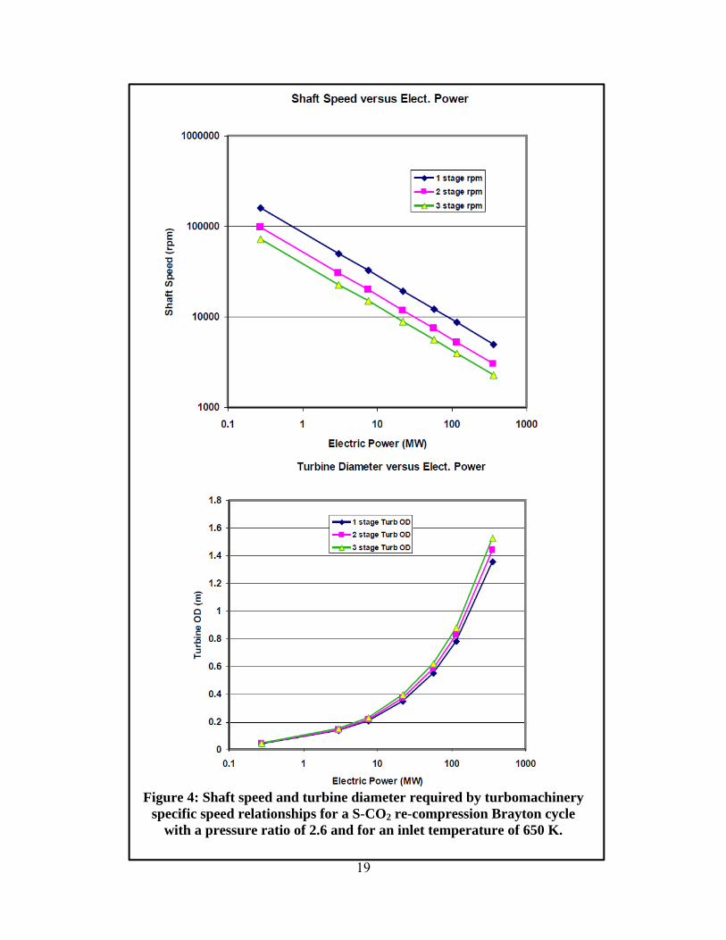
Where Ns is the specific speed, ω is the angular shaft speed, V is the volumetric flow rate, and dHad is the adiabatic change in enthalpy across the turbomachine. Once the power level is determined, the volumetric flow rate is determined as well as the change in enthalpy since it is parameterized by the pressure ratio and temperature of the thermodynamic cycle. Therefore, an angular shaft speed is chosen such that the specific speed is close to the ideal value of 1 for radial and axial flow turbomachines. This indicates that the rotational speed and size of the TM is constrained by the cycle parameters chosen, the gas type, and the power level of the system. A similar relationship is used to relate the tip speed of the compressor or turbine to the enthalpy change. The use of multiple stages of compression or expansion provides an additional degree of freedom for the designer. When multiple stages are used, the adiabatic enthalpy change is divided by the number of stages. Figure 4 shows the shaft speed and turbine diameter parameters characterized by a S-CO2 re-compression Brayton cycle over the power range from 0.1 MWe to about 300 MWe for one, two, and three stages of compression or expansion. As described earlier, low power level machines have very high shaft speeds and very small TM wheel diameters.

18
An early industry analysis of S-CO2 power systems funded by the Department of Energy (DOE) Advanced Reactor Concepts program recommended 3-4 stages of compression and expansion for large 300 MWe power systems. Both industry partners recommended radial compressors with three stages for the main compressor because they can accommodate large changes in density that may occur near the critical point. Likewise both industry reviews recommended axial turbines for the 300 MWe class with four stages of expansion because axial machines would be more efficient than in-flow radial turbines for commercial size power systems. The industrial designers considered both radial and axial re-compressors, which operate in a more conventional parameter space. Both recommended 3-4 stages of compression. These results are totally consistent with the plots presented in Figure 4.
19
Figure 4: Shaft speed and turbine diameter required by turbomachinery
specific speed relationships for a S-CO2 re-compression Brayton cycle with a pressure ratio of 2.6 and for an inlet temperature of 650 K.

20
5.2. Shaft Configuration, Number of Shafts, Gear Box
For large power plants (100 MWe and greater), it is likely that the turbomachinery train for the power plant be connected to one shaft that is connected to an external grid synchronous power generator, based on proper selection of the number of stages for the turbines and compressors. At the small-scale, proof of concept stage (<1 MWe), the motor/generator size was found to be limiting, thus the re-compression (split-flow) cycle was implemented using two shafts each with a turbo-alternator-compressor (TAC). This allowed the electronic powering the permanent magnet motor/generator to be of reasonable size and cost. Multiple shaft machines are thought to offer the advantage of allowing for rapid power changes and automatic load following as one machine can be operated a fixed frequency, while the other can be rapidly changed to increase or decrease power quickly. The small-scale demonstration system is the first of its kind, therefore the logical size of the system will be defined by the desire to use technologies that work, are prototypic of industrial power plants, and are affordable. A likely size range to investigate is the power range of 5-50 MWe. When two stages of compression and expansion are used, the shaft speeds for these systems would vary from 24,000 rpm to about 9,000 rpm, and the main compressor wheels would vary from about 0.1 m to 0.3 m. Smaller systems could be considered; however, the loss mechanisms for these systems will likely be fractionally large at these smaller sizes. Similarly, the components for the smaller sizes will likely be less prototypic. However, a 50 MWe power plant is quite large, and the costs to develop such a system would very likely be too expensive for the first small-scale demonstration system. Analysis performed at Sandia National Laboratories indicates that an appropriate size for the first prototype-scale demonstration plant should be in the power range of 3-20 MWe. This size may provide the best balance between cost and demonstration goals for the system. All further analysis at Sandia has focused on 7 -10 MWe for the plant, since this would allow installation of standard industrial components that mitigate the negative consequences from leakage flow and windage loss mechanisms. This size uses sufficiently large turbomachinery that possesses wheel efficiencies in the mid to high 80% range, rather than the conventional 65-75% range. Radial compressors and turbines are installed for this size, with the possibility of an axial turbine near the high-power end of the 3-20 MWe range. In addition, at 7 MWe or more, speeds are low enough to use a gear box to reduce the frequency to grid synchronous levels, allowing the usage of a standard synchronous motor/generator.
5.3. Bearings (Journal, Thrust)
A variety of bearing types can be considered for S-CO2 systems. The ones most commonly considered are:
1. Gas-foil bearings (appropriate for high speed small turbo machines provided the bearing rotor cavity pressure can be lowered to well below supercritical conditions)
2. Magnetic bearings (appropriate for intermediate size systems) 3. Hydro-static CO2 liquid or gas bearings (research and development required) 4. Hydro-dynamic CO2 liquid or supercritical fluid bearings (research and development
required)

21
5. Hydro-dynamic oil lubricated tilt-pad bearings (common industrial practice, but requires a buffer gas sealing system)
6. Hydro-dynamic oil lubricated roller or elliptical bearings
The first four types of bearings are very useful for specialty applications that may require hermetic (airtight) sealing of the S-CO2 loop. Gas foil bearings are used by Sandia National Laboratories and Barber Nichols in the small-scale test loops. Large industrial sized power plants rely mainly on oil lubricated tilt-pad hydro-dynamic bearings for both the thrust and journal bearings. In the 3-20 MWe size range, other bearing types could be considered, but based on knowledge gained from experience in the area, Sandia and Barber Nichols advocate the use of oil lubricated tilt pad bearings. The use of tilt pad bearings leverages the significant industrial investment in this technology, demonstrates the commercial technology for the S-CO2 Brayton cycle, and confirms that standard industrial seals and buffer gas management systems can be used with minimal loss in this application. Other types of bearings may still be important for specialty applications that may require hermetic applications (such as on a moving ship) including magnetic bearings, liquid CO2 hydrostatic or hydrodynamic bearings, and perhaps even gas-foil bearings. Figure 5 displays gas-foil bearings, the type used in the 1 MWth unit currently on-site at Sandia.
Figure 5: Gas-Foil Bearings used in the 1 MWth S-CO2 Brayton Cycle at Sandia National Laboratories. For a commercial-sized unit, these bearings would be replaced with more
appropriate components.
5.4. Seals
Seals are needed for all S-CO2 systems for two reasons: To reduce windage losses, which can be very high if large diameter shafts are spinning at high speeds in the high density fluid, and to isolate oil from oil bearings in the working fluid. The typical seal used in high-speed industrial turbomachinery are dry-gas lift-off seals. These seals are commercially available, have low leakage, and often use a buffer or purge gas to separate the working fluid (CO2 in this case) from the bearing cavity.

22
Ideally, the gas sealing system should be able to reduce the rotor cavity components to pressures that are nearly 100 psi to reduce windage losses, and the leakage through these seals should be on the order of less than 0.5% of the total flow system. Higher leakage rates can be tolerated but the power to pump the fluid back into the loop at 1100-1200 psi can be very large. Ultimately, this can represent a large loss mechanism in the system. A small scale demonstration loop at 7 – 10 MWe should demonstrate the combined use of oil lubricated tilt-pad bearings with dry-gas lift-off seals. Suppliers for these types of technologies include Flow Serve and John Crane, Inc.
5.5. Windage Losses
Windage losses can be significant if not properly managed. The windage loss model shown below was developed at NASA (Vrancik, 1968). In this model, the frictional losses are calculated from the geometry of the rotor and the properties of the fluid, given the Reynolds number of the fluid in the gap between the rotor and the stator. The equation for the windage losses is:
Where Cd is a discharge coefficient that is a function of the Reynolds number, ρ is the fluid density, r is the radius of the rotor, ω is the angular frequency of the rotor, and Lr is the length of the rotor. Note that the power is directly proportional to the fluid density, the shaft speed to the third power, and the radius of the rotor to the 4th power. This makes the actual power losses very sensitive to the shaft speed, size, and rotor cavity pressure. At a rotor cavity pressure of 100 psi, the fractional windage loss can be as high as 2% of the total generated power in a hermetically sealed system. To further reduce this windage, the S-CO2 power system must separate the power generation unit from the rotating turbomachinery. Thus, a small-scale demonstration system that uses a gas lift-off seal with a buffer gas to isolate the generator from the high pressure CO2 is required. The use of a gear box to reduce rotational generator speeds and a seal to reduce cavity pressures not only provides for a more conventional design, but also reduces the windage losses. However, this approach requires a high quality seal.
5.6. Gear Box Speed Reduction
The use of a gear box for speed reduction and the isolation of the working fluid from the power generator are common industrial practices. For the application proposed of a small-scale demonstration system at about 7 – 10 MWe, a gear reduction from a speed of 24,000 rpm to 3,600 rpm is required. This type of gear reduction is commercially available, but requires in-system cooling and represents a 0.5 – 1.0% power loss.

23
5.7. Motor/Generator and Control Electronics
Synchronous generators are used in most power plants that operate above 10 – 20 MWe, and they are always operated in power plants above 100 MWe. Due to extensive worldwide use, these are standard or near-standard commercial items. For the nominal 10 MWe demonstration plant, an induction generator could be considered as a replacement in order to save cost, but this will require a medium voltage grid to be present for operation.
5.8. Purge Gas Management
Dry-gas lift-off seals are most often used with a buffer or purge gas to isolate the working fluid gas from the lubrication environment. These types of systems are commercial components, often purchased from the gas seal supplier.
5.9. Heat Exchangers
One of the primary reasons for exploring the use of supercritical CO2 Brayton cycle systems is to reduce the size and potential cost of a plant’s power conversion system. The S-CO2 turbomachinery is very small due to the high density of the fluid, but the re-compression cycle requires the use of several gas heat exchangers: CO2-CO2 recuperators, one high-temperature heat exchanger (Na-CO2, for use with a liquid metal reactor), and a Water-CO2 waste heat rejection system. S-CO2 systems can operate at higher waste heat rejection temperatures that do not require water cooling, but this approach does involve an efficiency penalty that must be considered. To minimize capital costs, small, high-pressure heat exchangers are needed. The printed-circuit heat exchanger (PCHX), made by Heatric, is created by photo-etching small channels into sheets of steel or other alloys. The metal layers are then diffusion bonded together. Figure 6 shows a 0.5 MWth heat exchanger that is being used in the DOE Advanced Reactor Concepts re-compression S-CO2 Brayton cycle. Figure 6 also displays a view of the edge of the diffusion bonded photo-etched sheets.

24
Figure 6: Printed Circuit Heat Exchanger from Heatric. This is a water to CO2 heat exchanger sized for 0.51 MWth.
6. ROAD MAP FOR 10 MWE S-CO2 BRAYTON CYCLE TECHNOLOGY
The future of the S-CO2 Brayton cycle research directed by the DOE Advanced Reactor Concepts program is a 10 MWe system ready for commercial implementation. DOE has invested $10M since 2006, and that contribution is expected to increase significantly during the next stages of development for this technology. The scale up to 10 MWe is expected to cost $58M over four years. An estimate schedule and timeline are provided in order to more effectively display the program’s capital needs.
6.1. Rough Cost Estimates for 10 MWe S-CO2 Brayton Cycle System
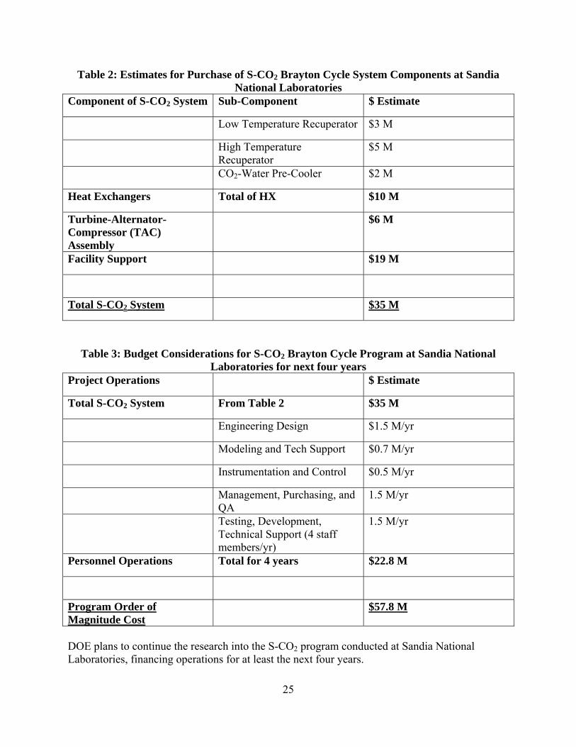
The estimate for the power conversion system provided earlier of $58M over 4 years is separated categorically below in Table 2 and Table 3.
25
Table 2: Estimates for Purchase of S-CO2 Brayton Cycle System Components at Sandia National Laboratories
Component of S-CO2 System Sub-Component $ Estimate
Low Temperature Recuperator $3 M
High Temperature Recuperator
$5 M
CO2-Water Pre-Cooler $2 M
Heat Exchangers Total of HX $10 M
Turbine-Alternator-Compressor (TAC) Assembly
$6 M
Facility Support $19 M
Total S-CO2 System $35 M
Table 3: Budget Considerations for S-CO2 Brayton Cycle Program at Sandia National Laboratories for next four years
Project Operations $ Estimate
Total S-CO2 System From Table 2 $35 M
Engineering Design $1.5 M/yr
Modeling and Tech Support $0.7 M/yr
Instrumentation and Control $0.5 M/yr
Management, Purchasing, and QA
1.5 M/yr
Testing, Development, Technical Support (4 staff members/yr)
1.5 M/yr
Personnel Operations Total for 4 years $22.8 M
Program Order of Magnitude Cost
$57.8 M
DOE plans to continue the research into the S-CO2 program conducted at Sandia National Laboratories, financing operations for at least the next four years.

26
7. TIMELINE FOR S-CO2 BRAYTON CYCLE PROGRAM
The S-CO2 Brayton Cycle Program is contained within the larger DOE Advanced Reactor Concepts program and has gained considerable acceptance as a viable direction for research into advanced power conversion systems. The program at Sandia National Laboratories will operate in four phases spread over the four years of DOE Advanced Reactor Concepts funding. Each stage of operation aims to achieve specific objectives and milestones throughout the project.
Phase One: Design (Conceptual, Preliminary, and Final)
o Scoping Calculations to Determine Power Cycle Type Efficiency Flow Rate Exact Number of Stages TM specifications
o Decision Points Proposed Vendors Proposed Materials Proposed Hardware
Phase Two: Purchasing, Fabrication, and Assembly of 10 MWe S-CO2 System o Delivery of S-CO2 System from Barber Nichols. o Installation of System On-site at Sandia National Laboratories. o Majority of funding will be spent during this phase due to purchasing of S-
CO2 system components. Phase Three: Commissioning, Upgrading, and Improvement
o Completion of Installation On-Site o Commission of the Power Unit o First Production of Electricity
Phase Four: Operations and Further Advances
o Final Operational Testing of System o Sale of Electricity back to the grid o Potential alteration of design in order to accommodate for future
modularization of the system

27
8. CONCLUSIONS
In order to effectively manufacture commercial sized S-CO2 power conversion systems, scaled test systems must be created in order to address potential issues with a full-scale design. The main scaling considerations concern the turbomachinery. Research at Sandia National Laboratories will focus on solving questions and issues with these areas/components: Power level of the system, turbine type, compressor type, bearing and seal styles, and generator implementation. The power level of the S-CO2 demonstration system ranges from 3 – 20 MWe, allowing most of the key TM components and features characteristic of a commercial scale system to be demonstrated. The speeds in this range are still above synchronous, but a gearbox would be used to transition from the nominal 20,000 rpm turbine speed to 3,600 rpm, permitting the use commercial generators and controls. The recommended size for the intermediate scaling demonstration is about 10 MWe. Refer back to Figure 1 in order to view the choices for the system components as a function of the power level of the system. The type of turbine used in a S-CO2 Brayton cycle varies based on the power level of the system. Radial turbines are used up to about 30 MWe, since axial blade heights would be too small to be efficient. However, above 30 MWe, axial turbines are appropriate with multiple stage units required at higher power levels, with the benefit of somewhat higher efficiency. For a 10 MWe intermediate demonstration system, a radial turbine is recommended. The main compressor of a S-CO2 Brayton cycle is likely to be a radial unit for most power levels (at least for the first stage) to assure more robust operations near the critical point. The re-compressor would transition to an axial unit above 100 MWe. For the 10 MWe unit, radial compressors will be chosen. At the 10 MWe level of the intermediate sized demonstration system, hydrodynamic bearings are available to use and would be the preferred approach. This allows implementation of the full-scale technology and takes advantage of the significant commercial expertise in this variety of bearings. The seal technology utilized in the demonstration system can leverage commercial experience in this area. Dry lift-off seals can be used at 10 MWe and above, therefore this is the recommended approach for both the intermediate sized demonstration system and a full-scale system. Finally, the use of a gear box to reduce the rotational speeds to synchronous speed allows the use of commercial generators for power conversion systems of 7 MWe and greater. Commercial gearboxes are available in the intermediate demonstration power and speed range. These would not be necessary above power levels of 50 MWe, since the rotation speeds are then compatible with synchronous operation. As Sandia National Laboratories moves forward in its S-CO2 Brayton cycle research, well-developed industrial turbomachinery and supporting technologies will help to establish this power conversion cycle as a cost-effective and efficient alternative.
28
9. FUTURE WORK
In the immediate future, Sandia National Laboratories will continue to pursue its research with the 1 MWth on-site loop to investigate performance and control characteristics, minimize inefficiencies, and further refine the bearing and seal requirements for larger-scale power systems. In addition, fabrication of larger power systems at Barber Nichols and delivery of those systems to Sandia National Laboratories will allow continued research on the scalability of the S-CO2 Brayton cycle. Delivery of the 1 MWth loop in early CY2012 provides Sandia researchers with the equipment necessary to explore all of the TM considerations outlined within this paper.

29
DISTRIBUTION
1 MS0721 Peter Davies, 6200 1 MS0736 Tito Bonano, 6220 5 MS1136 Gary Rochau, 6221 5 MS1136 Tom Conboy, 6221 5 MS1136 Darryn Fleming, 6221 1e MS1146 Ed Parma, 1384 5 MS1136 Jim Pasch, 6221 1e MS1136 Rob Sharpe, 6221 1e MS0899 Technical Library, 9536 (electronic copy)

30
THIS PAGE INTENTIONALLY LEFT BLANK