Embed Size (px)
Citation preview
W
AR
RA
NT
Y....
.Top
Flit
e M
odel
s gu
aran
tees
this
kit
to b
e fr
ee
from
def
ects
in b
oth
mat
eria
l and
wor
kman
ship
at t
he d
ate
of p
urch
ase.
Thi
s w
arra
nty
does
not
cov
er a
ny c
ompo
nent
par
ts d
amag
ed b
y us
e or
mod
ifi ca
tion.
In n
o c
ase
shal
l To
p F
lite’
s lia
bili
ty e
xcee
d th
e o
rig
inal
co
st o
f th
e p
urc
has
ed k
it. F
urth
er, T
op F
lite
rese
rves
the
right
to c
hang
e or
mod
ify th
is w
arra
nty
with
out n
otic
e.
In t
hat
Top
Flit
e ha
s no
con
trol
ove
r th
e fi n
al a
ssem
bly
or m
ater
ial
used
for
fi n
al
asse
mbl
y, n
o lia
bilit
y sh
all
be a
ssum
ed n
or a
ccep
ted
for
any
dam
age
resu
lting
fro
m
the
use
by t
he u
ser
of t
he fi
nal u
ser-
asse
mbl
ed p
rodu
ct. B
y th
e ac
t of
usi
ng t
he u
ser-
asse
mbl
ed p
rodu
ct, t
he u
ser
acce
pts
all r
esul
ting
liabi
lity.
If t
he
buye
r is
no
t p
rep
ared
to
acc
ept
the
liab
ility
ass
oci
ated
wit
h t
he
use
of
this
p
rod
uct
, th
e bu
yer
is a
dvi
sed
to
ret
urn
th
is k
it i
mm
edia
tely
in
new
an
d u
nu
sed
co
nd
itio
n t
o t
he
pla
ce o
f p
urc
has
e.
To m
ake
a w
arra
nty
clai
m s
end
the
defe
ctiv
e pa
rt o
r ite
m to
Hob
by S
ervi
ces
at th
e ad
dres
s:
Incl
ude
a le
tter s
tatin
g yo
ur n
ame,
retu
rn s
hipp
ing
addr
ess,
as
muc
h co
ntac
t inf
orm
atio
n as
pos
sibl
e (d
aytim
e te
leph
one
num
ber,
fax
num
ber,
e-m
ail
addr
ess)
, a
deta
iled
desc
riptio
n of
the
pro
blem
and
a p
hoto
copy
of
the
purc
hase
rec
eipt
. Upo
n re
ceip
t of
th
e pa
ckag
e th
e pr
oble
m w
ill b
e ev
alua
ted
as q
uick
ly a
s po
ssib
le.
RE
AD
TH
RO
UG
H T
HIS
MA
NU
AL
BE
FOR
E S
TAR
TIN
G C
ON
STR
UC
TIO
N. I
T C
ON
TAIN
S IM
PO
RTA
NT
INS
TRU
CTI
ON
S A
ND
WA
RN
ING
S C
ON
CE
RN
ING
TH
E A
SS
EM
BLY
AN
D U
SE
OF
THIS
MO
DE
L.
Hob
by S
ervi
ces
3002
N. A
pollo
Dr.
Sui
te 1
Cha
mpa
ign
IL 6
1822
US
A
Top
Flite
Mod
els
Cha
mpa
ign,
ILTe
leph
one
(217
) 398
-897
0, E
xt. 5
airs
uppo
rt@
top-
fl ite
.com
Ent
ire C
onte
nts
© C
opyr
ight
200
7TO
PZ
0980
for T
OPA
0980
V1.
0
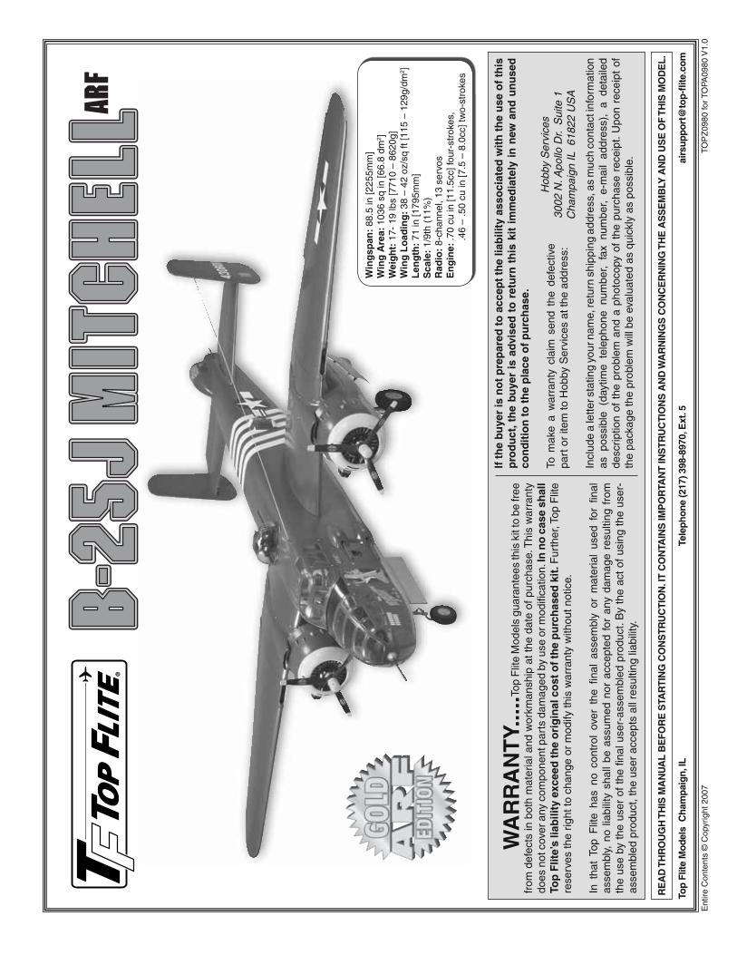
Win
gsp
an:
88.5
in [2
255m
m]
Win
g A
rea:
103
6 sq
in [6
6.8
dm2 ]
Wei
gh
t: 1
7- 1
9 lb
s [7
710
– 86
20g]
Win
g L
oad
ing
: 38
– 42
oz/
sq ft
[115
– 1
29g/
dm2 ]
Len
gth
: 71
in [1
795m
m]
Sca
le:
1/9t
h (1
1%)
Rad
io:
8-ch
anne
l, 13
ser
vos
En
gin
e: .7
0 cu
in [1
1.5c
c] fo
ur-s
trok
es,
.46
– .5
0 cu
in [7
.5 –
8.0
cc] t
wo-
stro
kes

2
TAB
LE
OF
CO
NT
EN
TS
INT
RO
DU
CT
ION
.....
......
......
......
......
......
......
......
......
2
Sca
le C
ompe
titio
n ...
......
......
......
......
......
......
......
...3
A
cade
my
of M
odel
Aer
onau
tics
......
......
......
......
....3
IM
AA
.....
......
......
......
......
......
......
......
......
......
......
....3
SA
FE
TY
PR
EC
AU
TIO
NS
.....
......
......
......
......
......
....3
DE
CIS
ION
S Y
OU
MU
ST
MA
KE
.....
......
......
......
......
.4
Eng
ine
Rec
omm
enda
tions
.....
......
......
......
......
......
4
Ret
ract
able
Lan
ding
Gea
r ....
......
......
......
......
......
...4
R
adio
Equ
ipm
ent .
......
......
......
......
......
......
......
......
.4A
DD
ITIO
NA
L IT
EM
S R
EQ
UIR
ED
.....
......
......
......
...5
H
ardw
are
and
Acc
esso
ries .
......
......
......
......
......
....5
A
dhes
ives
and
Bui
ldin
g S
uppl
ies .
......
......
......
......
.5
Opt
iona
l Sup
plie
s an
d To
ols
......
......
......
......
......
...5
C
over
ing
Tool
s ...
......
......
......
......
......
......
......
......
...5
KIT
INS
PE
CT
ION
.....
......
......
......
......
......
......
......
.....
6O
RD
ER
ING
RE
PL
AC
EM
EN
T P
AR
TS
.....
......
......
...6
PR
EPA
RA
TIO
N ..
......
......
......
......
......
......
......
......
.....
9A
SS
EM
BL
E T
HE
WIN
G P
AN
EL
S ..
......
......
......
......
.9
Hin
ge th
e F
laps
and
Aile
rons
.....
......
......
......
......
..9
M
ount
the
Eng
ines
.....
......
......
......
......
......
......
.....
10
Hoo
k U
p th
e T
hrot
tle a
nd In
stal
l the
Fue
l Tan
k ...
11
Mou
nt th
e M
ain
Land
ing
Gea
r ....
......
......
......
......
12
Ret
ract
Inst
alla
tion
......
......
......
......
......
......
......
.12
F
ixed
Gea
r In
stal
latio
n ....
......
......
......
......
......
...13
M
ount
the
Fib
ergl
ass
Nac
elle
Cov
ers
......
......
.....
13
Mou
nt th
e M
ain
Land
ing
Gea
r D
oors
(R
etra
cts
Onl
y) ..
......
......
......
......
......
......
......
....1
4
Hoo
k U
p th
e M
ain
Land
ing
Gea
r D
oors
.....
......
..16
M
ount
the
Cow
l .....
......
......
......
......
......
......
......
....1
9
Mou
nt th
e R
eplic
a E
ngin
es ..
......
......
......
......
......
.22
H
ook
Up
the
Fla
ps a
nd A
ilero
ns ..
......
......
......
.....
23A
SS
EM
BL
E T
HE
TA
IL ..
......
......
......
......
......
......
....2
4
Hin
ge th
e E
leva
tors
and
Rud
ders
.....
......
......
......
24
Hoo
k U
p th
e R
udde
rs a
nd E
leva
tors
.....
......
......
.25
M
ount
the
Nos
e G
ear .
......
......
......
......
......
......
....2
6
Hoo
k U
p th
e N
ose
Gea
r D
oor
(R
etra
ct O
nly)
.....
......
......
......
......
......
......
......
...29
FIN
AL
AS
SE
MB
LY ..
......
......
......
......
......
......
......
...30
A
ssem
ble
the
Coc
kpit
......
......
......
......
......
......
.....
30
Hoo
k U
p th
e A
ir S
yste
m ..
......
......
......
......
......
.....
31
Com
plet
e th
e R
adio
Inst
alla
tion
......
......
......
......
..32
M
ount
the
Inbo
ard
Win
g P
anel
s ....
......
......
......
....3
3
Mou
nt th
e O
utbo
ard
Win
g P
anel
s ....
......
......
......
.34
SC
AL
E F
EA
TU
RE
S ..
......
......
......
......
......
......
....3
535
M
ount
the
Nos
e-G
unne
r C
anop
y ....
......
......
......
..37
In
stal
l the
Nos
e-G
unne
r C
abin
.....
......
......
......
....3
8
Mou
nt th
e To
p Tu
rret
& M
achi
ne G
uns.
......
......
...38
F
inis
h th
e Ta
il-G
unne
r C
abin
.....
......
......
......
......
.39
M
ount
Sid
e G
un P
acks
& W
aist
Gun
Win
dow
s ...
40
Mou
nt th
e A
DF
“F
ootb
all”
Ant
enna
.....
......
......
....4
1
Mou
nt th
e P
rope
ller
Hub
s ...
......
......
......
......
......
..41
A
pply
the
Dec
als .
......
......
......
......
......
......
......
......
41G
ET
TH
E M
OD
EL
RE
AD
Y T
O F
LY ..
......
......
......
...41
B
alan
ce th
e M
odel
(C
.G.)
.....
......
......
......
......
......
42
Bal
ance
the
Mod
el L
ater
ally
.....
......
......
......
......
..42
PR
EF
LIG
HT
.....
......
......
......
......
......
......
......
......
.....
42
Che
ck th
e C
ontr
ol D
irect
ions
.....
......
......
......
......
.43
S
et th
e C
ontr
ol T
hrow
s ...
......
......
......
......
......
......
43
Iden
tify
Your
Mod
el ..
......
......
......
......
......
......
......
.43
C
harg
e th
e B
atte
ries .
......
......
......
......
......
......
......
43
Bal
ance
Pro
pelle
rs ..
......
......
......
......
......
......
......
.43
G
roun
d C
heck
......
......
......
......
......
......
......
......
.....
43
Ran
ge C
heck
.....
......
......
......
......
......
......
......
......
.44
EN
GIN
E S
AF
ET
Y P
RE
CA
UT
ION
S ...
......
......
......
..44
AM
A S
AF
ET
Y C
OD
E (
Exc
erp
ts) .
......
......
......
......
44C
HE
CK
LIS
T ..
......
......
......
......
......
......
......
......
......
.45
FLY
ING
.....
......
......
......
......
......
......
......
......
......
......
.45
M
ount
the
Win
gs ..
......
......
......
......
......
......
......
.....
45
Take
off .
......
......
......
......
......
......
......
......
......
......
...46
F
light
.....
......
......
......
......
......
......
......
......
......
......
..46
B
-25
Eng
ine-
Out
Fly
ing
Pro
cedu
res
......
......
......
.46
S
ingl
e E
ngin
e-O
ut P
roce
dure
s ...
......
......
......
......
46
Land
ing
......
......
......
......
......
......
......
......
......
......
...47
SE
RV
O E
XT
EN
SIO
N C
HA
RT
S ...
......
......
......
......
..48
EN
GIN
E M
OU
NT
TE
MP
LA
TE
S ..
......
......
......
......
..51
INT
RO
DU
CT
ION
Tha
nk y
ou f
or p
urch
asin
g th
e To
p F
lite
Gol
d E
ditio
n 1/
9th-s
cale
B-2
5J M
itche
ll A
RF.
Whi
le n
o A
RF
mod
el
will
pr
ovid
e th
e le
vel
of
deta
il ne
cess
ary
to
take
“h
igh-
stat
ic”
at p
rem
ier
scal
e co
mpe
titio
ns,
you’
ll st
ill
be a
maz
ed a
t th
e le
vel
of d
etai
l an
d th
e nu
mbe
r of
sc
ale
feat
ures
inc
lude
d w
ith t
his
mod
el!
And
we’
ve
done
our
bes
t to
bala
nce
the
leve
l of a
uthe
ntic
ity a
nd
deta
il w
ith th
e re
quire
men
ts fo
r sim
plic
ity th
at a
n A
RF
m
odel
er e
xpec
ts. F
or e
xam
ple,
the
mai
n la
ndin
g ge
ar
door
s on
the
ful
l-siz
e B
-25
clos
e bo
th a
fter
the
gear
ha
s re
trac
ted
and
afte
r it h
as e
xten
ded
(look
at p
hoto
s of
a B
-25
sitti
ng o
n th
e ta
rmac
—no
tice
that
the
gea
r do
ors
are
clos
ed!)
. B
ut r
athe
r th
an d
uplic
atin
g th
e fu
ll-si
ze c
onfi g
urat
ion
(whi
ch w
ould
req
uire
a l
arge
r ra
dio
with
add
ition
al c
hann
els,
air
cont
rol
valv
es o
n ev
ery
door
, ad
ditio
nal
push
rods
, lin
kage
s, a
ir lin
es,
sequ
ence
rs
and
cons
ider
able
tim
e,
expe
nse
and
skill
), a
nd r
athe
r th
an a
band
onin
g fu
nctio
ning
doo
rs
alto
geth
er, w
e di
d it
the
“har
d w
ay” b
ack
in th
e sh
op b
y ta
king
tim
e to
fi gu
re o
ut h
ow to
inco
rpor
ate
oper
atin
g,
scal
e-ap
pear
ing
land
ing
gear
doo
rs th
at th
e av
erag
e A
RF
bui
lder
cou
ld b
oth
affo
rd a
nd a
ssem
ble.
The
To
p F
lite
B-2
5 A
RF
feat
ures
ope
ratin
g, s
prin
g-lo
aded
do
ors
that
use
mec
hani
cal l
ever
s to
ope
n an
d cl
ose,
th
us e
limin
atin
g al
l the
afo
rem
entio
ned
para
pher
nalia
th
at w
ould
be
requ
ired.
And
whi
le o
ther
sca
le d
etai
ls i
nclu
ding
the
nos
e-gu
nner
int
erio
r, co
ckpi
t in
terio
r, ta
il-gu
nner
can
opy
and
mac
hine
gun
s ar
e no
t exa
ct re
plic
as, t
hese
sca
le
feat
ures
stil
l “ge
t the
poi
nt a
cros
s” w
ith th
eir p
rese
nce
and
stan
d-of
f acc
urac
y. W
ith a
ll th
is d
etai
l als
o co
mes
th
e tim
e co
mm
itmen
t to
put
it a
ll to
geth
er,
but
in t
he
end
we
know
it
will
all
be w
orth
whi
le w
hen
you’
re
exec
utin
g sl
ow fl
y-by
s st
raig
ht d
own
the
runw
ay w
ith
the
fl aps
and
gea
r ex
tend
ed a
nd e
very
body
els
e at
th
e fi e
ld s
tand
ing
by w
atch
ing.
The
“Gol
d” B
-25
is a
lso
a us
er-fr
iend
ly m
odel
for b
reak
ing
dow
n fo
r tra
nspo
rt a
nd s
et u
p. M
ost m
odel
ers
will
sim
ply
rem
ove
the
outb
oard
win
g pa
nels
allo
win
g th
e m
odel
to
fi t e
asily
into
a m
ini v
an. I
f it’
s st
ill t
oo b
ig,
the
inbo
ard
win
g pa
nels
and
ver
tical
and
hor
izon
tal s
tabi
lizer
s ca
n al
so b
e ea
sily
rem
oved
with
the
stu
rdy
build
ing
stan
d su
ppor
ting
the
mod
el d
urin
g th
e pr
oces
s.
For
the
late
st te
chni
cal u
pdat
es o
r man
ual c
orre
ctio
ns
to th
is m
odel
vis
it th
e To
p F
lite
web
site
at w
ww
.to
p-
fl it
e.co
m. O
pen
the
“GO
LD E
DIT
ION
AR
FS
” lin
k on
th
e le
ft si
de o
f the
pag
e an
d cl
ick
on im
age
of th
e B
-25
that
app
ears
. If
ther
e is
new
tec
hnic
al in
form
atio
n or
ch
ange
s th
ere
will
be
an “
Impo
rtan
t! T
EC
H N
OT
ICE
” bo
x on
the
uppe
r le
ft co
rner
of t
he p
age.
Clic
k on
the
Tech
Not
ice
box
to r
ead
the
info
.
3
SC
AL
E C
OM
PE
TIT
ION
The
sca
le o
f th
is m
odel
is
1/9th
(or
11%
). T
hese
fi g
ures
wer
e de
rived
fro
m c
ompa
ring
the
win
g sp
an
and
fuse
lage
leng
th o
f thi
s m
odel
to th
e w
ings
pan
and
fuse
lage
len
gth
of t
he f
ull-s
ize.
Tho
ugh
the
Top
Flit
e B
-25J
Mitc
hell
is a
n A
RF
and
may
not
hav
e th
e sa
me
leve
l of
deta
il as
an
“all-
out”
scra
tch-
built
com
petit
ion
mod
el, i
t is
a sc
ale
mod
el n
onet
hele
ss a
nd is
ther
efor
e el
igib
le t
o co
mpe
te i
n th
e F
un S
cale
cla
ss i
n A
MA
co
mpe
titio
n (w
e re
ceiv
e m
any
favo
rabl
e re
port
s of
ou
r A
RF
s in
sca
le c
ompe
titio
n!).
In F
un S
cale
, th
e “b
uild
er o
f th
e m
odel
” ru
le d
oes
not
appl
y. T
o re
ceiv
e th
e fi v
e po
ints
for
scal
e do
cum
enta
tion,
the
only
pro
of
requ
ired
that
a fu
ll si
ze a
ircra
ft of
this
type
in th
is p
aint
/m
arki
ngs
sche
me
did
exis
t is
a si
ngle
she
et s
uch
as a
ki
t box
cov
er fr
om a
pla
stic
mod
el, a
pho
to, o
r a p
rofi l
e pa
intin
g, e
tc. I
f a b
lack
-and
-whi
te p
hoto
is u
sed,
oth
er
writ
ten
docu
men
tatio
n of
co
lor
mus
t be
pr
ovid
ed.
Con
tact
the
AM
A fo
r a
rule
boo
k w
ith fu
ll de
tails
. See
be
low
for
the
AM
A c
onta
ct in
form
atio
n.
If yo
u w
ould
lik
e ph
otos
of
the
full-
size
B-2
5J f
or
scal
e do
cum
enta
tion,
or
if yo
u w
ould
like
to s
tudy
the
phot
os t
o ad
d m
ore
scal
e de
tails
, ph
oto
pack
s ar
e av
aila
ble
from
:
Bob
’s A
ircra
ft D
ocum
enta
tion
3114
Yuk
on A
veC
osta
Mes
a, C
A 9
2626
Tele
phon
e: (
714)
979
-805
8Fa
x: (
714)
979
-727
9e-
mai
l: w
ww
.bo
bsa
ird
oc.
com
AC
AD
EM
Y O
F M
OD
EL
AE
RO
NA
UT
ICS
If yo
u ar
e no
t al
read
y a
mem
ber
of t
he A
MA
, pl
ease
jo
in!
The
A
MA
is
th
e go
vern
ing
body
of
m
odel
av
iatio
n an
d m
embe
rshi
p pr
ovid
es li
abili
ty in
sura
nce
cove
rage
, pro
tect
s m
odel
ers’
rig
hts
and
inte
rest
s an
d is
req
uire
d to
fl y
at m
ost R
/C s
ites.
Aca
dem
y o
f M
od
el A
ero
nau
tics
5151
Eas
t Mem
oria
l Driv
eM
unci
e, IN
473
02-9
252
Tele
. (80
0) 4
35-9
262
Fax
(765
) 74
1-00
57O
r vi
a th
e In
tern
et a
t: h
ttp
://w
ww
.mo
del
airc
raft
.org
IMP
OR
TAN
T!!
! Tw
o of
the
mos
t im
port
ant t
hing
s yo
u ca
n do
to p
rese
rve
the
radi
o co
ntro
lled
airc
raft
hobb
y ar
e to
avo
id fl
yin
g ne
ar f
ull-s
cale
airc
raft
and
avoi
d fl y
ing
near
or
over
gro
ups
of p
eopl
e.
IMA
A
The
Top
Flit
e B
-25
AR
F q
ualifi
es
as a
“gia
nt-s
cale
” mod
el
and
is t
here
fore
elig
ible
to
fl y i
n IM
AA
(In
tern
atio
nal
Min
iatu
re A
ircra
ft A
ssoc
iatio
n) e
vent
s. T
he IM
AA
is a
n or
gani
zatio
n th
at p
rom
otes
non
-com
petit
ive
fl yin
g of
gi
ant-
scal
e m
odel
airc
raft.
If y
ou p
lan
on a
ttend
ing
an
IMA
A e
vent
ref
er t
o th
e IM
AA
Saf
ety
Co
de
at w
ww
.fl
y-im
aa.o
rg u
nder
the
“S
anct
ions
” he
adin
g in
the
ir si
te in
dex.
IM
AA
con
tact
info
rmat
ion
is a
lso
avai
labl
e in
Mod
el A
viat
ion,
the
mon
thly
new
slet
ter
mag
azin
e fr
om th
e A
MA
. The
IMA
A c
an a
lso
be c
onta
cted
at t
he
addr
ess
or te
leph
one
num
ber
belo
w:
IMA
A20
5 S
. Hill
dale
Roa
dS
alin
a, K
S 6
7401
(913
) 82
3-55
69
PR
OT
EC
T Y
OU
R
MO
DE
L,
YO
UR
SE
LF
A
ND
O
TH
ER
S. F
OL
LO
W T
HE
SE
IMP
OR
TAN
TS
AF
ET
Y P
RE
CA
UT
ION
S
1. Y
our
Top
Flit
e B
-25J
Mitc
hell
AR
F s
houl
d no
t be
co
nsid
ered
a t
oy,
but
rath
er a
sop
hist
icat
ed,
wor
king
m
odel
th
at
func
tions
ve
ry
muc
h lik
e a
full-
size
ai
rpla
ne. B
ecau
se o
f its
per
form
ance
cap
abili
ties,
the
B-2
5 A
RF,
if
not
asse
mbl
ed a
nd o
pera
ted
corr
ectly
, co
uld
poss
ibly
cau
se in
jury
to
your
self
or s
pect
ator
s an
d da
mag
e to
pro
pert
y.
2. Y
ou m
ust
asse
mbl
e th
e m
odel
acc
ord
ing
to
th
e in
stru
ctio
ns.
Do
not
alte
r or
mod
ify t
he m
odel
, as
do
ing
so m
ay r
esul
t in
an
unsa
fe o
r un
fl yab
le m
odel
. In
a fe
w c
ases
the
inst
ruct
ions
may
diff
er s
light
ly fr
om
the
phot
os. I
n th
ose
inst
ance
s th
e w
ritte
n in
stru
ctio
ns
shou
ld b
e co
nsid
ered
as
corr
ect.
3. Y
ou m
ust t
ake
time
to b
uild
str
aig
ht,
tru
ean
d st
ron
g.
4. Y
ou m
ust
use
an R
/C r
adio
sys
tem
tha
t is
in g
ood
cond
ition
and
cor
rect
ly s
ized
eng
ine
and
com
pone
nts
as s
peci
fi ed
in th
is in
stru
ctio
n m
anua
l. A
ll co
mpo
nent
s m
ust b
e co
rrec
tly in
stal
led
so th
at th
e m
odel
ope
rate
s co
rrec
tly o
n th
e gr
ound
and
in th
e ai
r. Yo
u m
ust c
heck
th
e op
erat
ion
of th
e m
odel
and
all
com
pone
nts
befo
re
ever
y fl i
ght.
5. I
f yo
u ar
e no
t an
exp
erie
nced
pilo
t or
hav
e no
t fl o
wn
this
typ
e of
mod
el b
efor
e, w
e re
com
men
d th
at
you
get t
he a
ssis
tanc
e of
an
expe
rienc
ed p
ilot i
n yo
ur
R/C
clu
b fo
r yo
ur fi
rst
fl ig
hts.
If
you’
re n
ot a
mem
ber
of a
clu
b, y
our
loca
l ho
bby
shop
has
inf
orm
atio
n ab
out c
lubs
in y
our a
rea
who
se m
embe
rshi
p in
clud
es
expe
rienc
ed p
ilots
.
6. W
hile
thi
s ki
t ha
s be
en fl
ight
tes
ted
to e
xcee
d no
rmal
use
, if
the
plan
e w
ill b
e us
ed f
or e
xtre
mel
y hi
gh s
tres
s fl y
ing,
or
if en
gine
s la
rger
tha
n on
es i
n th
e re
com
men
ded
rang
e ar
e us
ed,
the
mod
eler
is
resp
onsi
ble
for
taki
ng s
teps
to
rein
forc
e th
e hi
gh
stre
ss
poin
ts
and/
or
subs
titut
ing
hard
war
e m
ore
suita
ble
for
the
incr
ease
d st
ress
.
4
9. W
AR
NIN
G:
Som
e of
the
part
s in
this
kit
are
mad
e of
fi b
ergl
ass,
the
fi b
ers
of w
hich
may
cau
se e
ye,
skin
and
res
pira
tory
tra
ct i
rrita
tion.
Nev
er b
low
int
o on
e of
the
se p
arts
to
rem
ove
fi ber
glas
s du
st,
as
the
dust
will
blo
w b
ack
into
you
r ey
es.
Alw
ays
wea
r sa
fety
gog
gles
, a
part
icle
mas
k an
d ru
bber
glo
ves
whe
n gr
indi
ng,
drill
ing
and
sand
ing
fi ber
glas
s pa
rts.
V
acuu
m th
e pa
rts
and
the
wor
k ar
ea th
orou
ghly
afte
r w
orki
ng w
ith fi
berg
lass
par
ts.
We,
as
the
kit m
anuf
actu
rer,
prov
ide
you
with
a to
p qu
ality
, th
orou
ghly
tes
ted
kit
and
inst
ruct
ions
, bu
t ul
timat
ely
the
qual
ity a
nd fl
yabi
lity
of y
our
fi nis
hed
mod
el d
epen
ds o
n ho
w y
ou b
uild
it; t
here
fore
, w
e ca
nnot
in a
ny w
ay g
uara
ntee
the
per
form
ance
of
your
com
plet
ed m
odel
, an
d no
rep
rese
ntat
ions
ar
e ex
pres
sed
or im
plie
d as
to th
e pe
rfor
man
ce o
r sa
fety
of y
our
com
plet
ed m
odel
.
Rem
emb
er:
Take
yo
ur
tim
e an
d
follo
w
the
inst
ruct
ion
s to
en
d u
p w
ith
a w
ell-
built
mo
del
that
is
str
aig
ht
and
tru
e.
DE
CIS
ION
S Y
OU
MU
ST
MA
KE
Thi
s is
a p
artia
l lis
t of
ite
ms
requ
ired
to fi
nis
h th
is
mod
el t
hat
may
req
uire
pla
nnin
g or
dec
isio
n m
akin
g be
fore
sta
rtin
g as
sem
bly.
Ord
er n
umbe
rs a
re p
rovi
ded
in p
aren
thes
es.
EN
GIN
E R
EC
OM
ME
ND
AT
ION
S
As
spec
ifi ed
on
the
fron
t cov
er o
f thi
s in
stru
ctio
n m
anua
l, th
e To
p F
lite
B-2
5J A
RF
is in
tend
ed fo
r tw
in .
70 fo
ur-
stro
kes
or .4
6-.5
0 tw
o-st
roke
s. T
here
isn’
t muc
h m
ore
that
can
be
said
oth
er t
han
it is
unn
eces
sary
(as
wel
l as
ina
dvis
able
) to
ove
rpow
er t
his
mod
el w
ith l
arge
r en
gine
s. E
ngin
es i
n th
e sp
ecifi
ed r
ange
will
pro
vide
m
ore
than
eno
ugh
thru
st to
fl y
this
mod
el in
a s
cale
-like
m
anne
r w
ith p
lent
y of
ext
ra p
ower
to
perfo
rm e
vasi
ve
man
euve
rs i
f th
e si
tuat
ion
aris
es.
Bot
tom
lin
e is
with
tw
o-st
roke
.46’
s or
four
-str
oke
.70’
s yo
u’ll
fi nd
your
self
crui
sing
aro
und
at h
alf-
thro
ttle
mos
t of t
he ti
me.
RE
TR
AC
TAB
LE
LA
ND
ING
GE
AR
Your
B-2
5J M
itche
ll A
RF
may
be
asse
mbl
ed w
ith th
e in
clud
ed fi
xed
lan
ding
gea
r or
ret
ract
able
lan
ding
ge
ar. I
f fi x
ed la
ndin
g ge
ar is
use
d, n
o ad
ditio
nal i
tem
s w
ill b
e ne
eded
to in
stal
l the
gea
r. If
inst
allin
g re
trac
ts,
this
mod
el is
des
igne
d fo
r R
obar
t pne
umat
ic r
etra
cts.
F
ollo
win
g is
the
com
plet
e lis
t of
ite
ms
requ
ired
to
inst
all t
he R
obar
t ret
ract
s:
❏ R
obar
t #T
FB
25 T
op F
lite
B-2
5J A
RF
pne
umat
ic
retr
acta
ble
mai
n la
ndin
g ge
ar (
RO
BQ
1624
)❏
Rob
art
#157
VR
X L
arge
-Sca
le D
elux
e A
ir C
ontr
ol
Kit—
incl
udes
pr
essu
re
vess
el,
air
line
tubi
ng,
varia
ble-
rate
air
valv
e, T
-fi tt
ings
(R
OB
Q23
05)
❏ #
190
Air
Line
Qui
ck D
isco
nnec
ts (
RO
BQ
2395
)❏
Sta
ndar
d si
ze s
ervo
to o
pera
te a
ir co
ntro
l val
ve
Add
ition
ally
, a
hobb
y ca
n of
com
pres
sed
air
such
as
H
obbi
co
Dus
ter™
(H
CA
R55
00)
will
be
he
lpfu
l fo
r cy
clin
g th
e re
trac
ts d
urin
g as
sem
bly
and
setu
p w
ithou
t ha
ving
to
conn
ect
the
gear
to
the
air
cont
rol
valv
e, fi
ller
and
air
tank
bef
ore
it is
rea
dy.
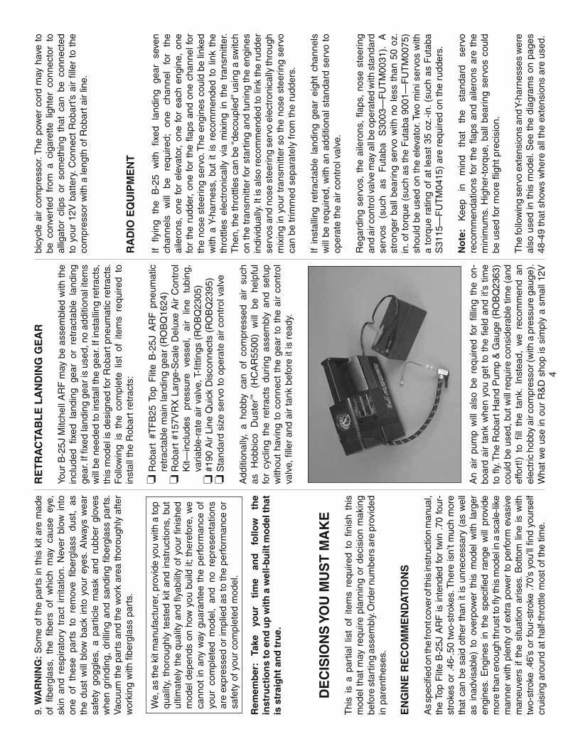
An
air
pum
p w
ill a
lso
be r
equi
red
for
fi llin
g th
e on
-bo
ard
air
tank
whe
n yo
u ge
t to
the
fi e
ld a
nd it
’s t
ime
to fl
y. T
he R
obar
t Han
d P
ump
& G
auge
(R
OB
Q23
63)
coul
d be
use
d, b
ut w
ill r
equi
re c
onsi
dera
ble
time
(and
ef
fort
!) t
o fi l
l th
e ta
nk.
Inst
ead,
we
reco
mm
end
an
elec
tric
hob
by a
ir co
mpr
esso
r (w
ith a
pre
ssur
e ga
uge)
. W
hat
we
use
in o
ur R
&D
sho
p is
sim
ply
a sm
all 1
2V
bicy
cle
air
com
pres
sor.
The
pow
er c
ord
may
hav
e to
be
con
vert
ed f
rom
a c
igar
ette
lig
hter
con
nect
or t
o al
ligat
or c
lips
or s
omet
hing
tha
t ca
n be
con
nect
ed
to y
our
12V
bat
tery
. Con
nect
Rob
art’s
air
fi lle
r to
the
co
mpr
esso
r w
ith a
leng
th o
f Rob
art a
ir lin
e.
RA
DIO
EQ
UIP
ME
NT
If fl y
ing
the
B-2
5 w
ith
fi xed
la
ndin
g ge
ar
seve
n ch
anne
ls
will
be
re
quire
d;
one
chan
nel
for
the
aile
rons
, on
e fo
r el
evat
or,
one
for
each
eng
ine,
one
fo
r th
e ru
dder
, on
e fo
r th
e fl a
ps a
nd o
ne c
hann
el fo
r th
e no
se s
teer
ing
serv
o. T
he e
ngin
es c
ould
be
linke
d w
ith a
Y-h
arne
ss,
but
it is
rec
omm
ende
d to
lin
k th
e th
rottl
es e
lect
roni
cally
via
mix
ing
in t
he t
rans
mitt
er.
The
n, th
e th
rottl
es c
an b
e “d
ecou
pled
” usi
ng a
sw
itch
on th
e tr
ansm
itter
for
star
ting
and
tuni
ng th
e en
gine
s in
divi
dual
ly. I
t is
also
rec
omm
ende
d to
link
the
rudd
er
serv
os a
nd n
ose
stee
ring
serv
o el
ectr
onic
ally
thro
ugh
mix
ing
in y
our
tran
smitt
er s
o th
e no
se s
teer
ing
serv
o ca
n be
trim
med
sep
arat
ely
from
the
rudd
ers.
If in
stal
ling
retr
acta
ble
land
ing
gear
eig
ht c
hann
els
will
be
requ
ired,
with
an
addi
tiona
l sta
ndar
d se
rvo
to
oper
ate
the
air
cont
rol v
alve
.
Reg
ardi
ng s
ervo
s, t
he a
ilero
ns,
fl aps
, no
se s
teer
ing
and
air c
ontr
ol v
alve
may
all
be o
pera
ted
with
sta
ndar
d se
rvos
(s
uch
as
Fut
aba
S30
03—
FU
TM
0031
). A
st
rong
er b
all b
earin
g se
rvo
with
no
less
tha
n 50
oz.
in
. of t
orqu
e (s
uch
as th
e F
utab
a 90
01—
FU
TM
0075
) sh
ould
be
used
on
the
elev
ator
. Tw
o m
ini s
ervo
s w
ith
a to
rque
rat
ing
of a
t le
ast
35 o
z.-in
. (su
ch a
s F
utab
a S
3115
—F
UT
M04
15)
are
requ
ired
on th
e ru
dder
s.
No
te:
Kee
p in
m
ind
that
th
e st
anda
rd
serv
o re
com
men
datio
ns f
or t
he fl
aps
and
aile
rons
are
the
m
inim
ums.
Hig
her-
torq
ue,
ball
bear
ing
serv
os c
ould
be
use
d fo
r m
ore
fl igh
t pre
cisi
on.
The
follo
win
g se
rvo
exte
nsio
ns a
nd Y
-har
ness
es w
ere
also
use
d in
thi
s m
odel
. See
the
dia
gram
s on
pag
es
48-4
9 th
at s
how
s w
here
all
the
exte
nsio
ns a
re u
sed.

5
❏ (4
) 6"
[150
mm
] ext
ensi
ons
(HC
AM
2701
for
Fut
aba)
❏ (2
) 12"
[300
mm
] ext
ensi
ons
(HC
AM
2711
for F
utab
a)❏
(5) 2
4" [6
00m
m] e
xten
sion
s (H
CA
M27
21 fo
r Fut
aba)
❏ (1
) 36
" [9
10m
m] e
xten
sion
(H
CA
M27
26 fo
r F
utab
a)❏
(5) Y
-har
ness
es (
HC
AM
2751
for
Fut
aba)
A
min
imum
2,
000m
Ah
rece
iver
ba
ttery
co
uld
be
used
, but
you
will
hav
e to
clo
sely
mon
itor t
he b
atte
ry’s
ca
paci
ty a
nd v
olta
ge t
o av
oid
drai
ning
the
bat
tery
to
o fa
r. A
bat
tery
lar
ger
than
2,0
00m
Ah
wou
ld b
e m
ore
suita
ble
and
prov
ide
mor
e fl i
ght
time
betw
een
char
ges.
Fol
low
ing
are
two
suita
ble
batte
ry p
acks
:
❏ H
ydriM
ax™
Ultr
a 4.
8V 4
,200
mA
h su
b C
NiM
H
rece
iver
bat
tery
w/F
utab
a co
nnec
tor
(HC
AM
6335
)❏
Hyd
riMax
Ultr
a 4.
8V 2
,000
mA
h A
A N
iMH
rece
iver
ba
ttery
w/F
utab
a co
nnec
tor
(HC
AM
6321
)
AD
DIT
ION
AL
ITE
MS
RE
QU
IRE
D
HA
RD
WA
RE
AN
D A
CC
ES
SO
RIE
S
In a
dditi
on t
o th
e ite
ms
liste
d in
the
“D
ecis
ion
s Yo
u
Mu
st M
ake”
sec
tion,
follo
win
g is
the
list o
f har
dwar
e an
d ac
cess
orie
s re
quire
d to
fi n
ish
the
B-2
5. O
rder
nu
mbe
rs a
re p
rovi
ded
in p
aren
thes
es.
❏ 1
/4"
R/C
Foa
m R
ubbe
r (H
CA
Q10
00)
❏ 3
' [90
0mm
] Sta
ndar
d S
ilico
ne F
uel
Tubi
ng (
GP
MQ
4131
)❏
Ern
st #
124
Cha
rge
Rec
epta
cle
❏ S
tick-
on S
egm
ente
d Le
ad W
eigh
ts (
GP
MQ
4485
)❏
Pro
pelle
rs (
and
spar
es)
suita
ble
for
your
eng
ines
AD
HE
SIV
ES
AN
D B
UIL
DIN
G S
UP
PL
IES
In a
dditi
on t
o co
mm
on h
obby
too
ls a
nd h
ouse
hold
to
ols,
thi
s is
the
“sh
ort
list”
of t
he m
ost
impo
rtan
t ite
ms
requ
ired
to b
uild
the
B-2
5 A
RF.
Gre
at P
lan
es
Pro
™ C
A a
nd E
poxy
glu
e ar
e re
com
men
ded.
Fore
mos
t, a
Gre
at P
lane
s S
tand
ard
3/32
" B
all W
ren
ch
(GP
MR
8002
) an
d a
Gre
at P
lane
s S
tand
ard
.050
" B
all W
ren
ch (
GP
MR
8000
) ar
e vi
rtua
l nec
essi
ties
for
asse
mbl
ing
this
mod
el. T
hese
are
lon
g-ha
ndle
Alle
n w
renc
hes
that
will
be
inva
luab
le f
or m
ount
ing
the
cow
ls a
nd o
ther
the
scal
e de
tails
.
❏ 1
oz.
[30g
] Thi
n P
ro C
A (
GP
MR
6002
)❏
1 o
z. [3
0g] M
ediu
m P
ro C
A+
(G
PM
R60
08)
❏ C
A A
pplic
ator
Tip
s (H
CA
R37
80)
❏ C
A A
ctiv
ator
2 o
z. [5
7g] S
pray
Bot
tle (G
PM
R60
35),
or
4 o
z. [1
13g]
Aer
osol
(G
PM
R63
4)❏
Pro
30-
Min
ute
Epo
xy (
GP
MR
6047
)❏
Mill
ed F
iber
glas
s (G
PM
R61
65) -
OR
- Mic
roba
lloon
s (T
OP
R10
90)
❏ T
hrea
dloc
ker T
hrea
d Lo
ckin
g C
emen
t (G
PM
R60
60)
❏ #
1 H
obby
Kni
fe (
HC
AR
0105
)❏
#11
Bla
des
(5-p
ack,
HC
AR
0211
)❏
#11
Bla
des
(100
-pac
k, H
CA
R03
11)
❏ D
rill B
its: 1
/16"
[1.6
mm
], 5/
64" [
2mm
], 3/
32" [
2.4m
m],
7/64
" [2.
8mm
], 1/
8" [3
.2m
m],
5/32
" [4m
m],
#29
Dril
l an
d 4-
40 T
ap (
or G
reat
Pla
nes
4-40
Tap
and
Dril
l S
et (
GP
MR
8101
)❏
Tap
han
dle
(GP
MR
8120
)❏
Sol
derin
g Ir
on o
r H
obby
Hea
t™ M
icro
Tor
ch II
(H
CA
R07
55)
❏ S
ilver
Sol
der
w/F
lux
(GP
MR
8070
)❏
Den
atur
ed A
lcoh
ol fo
r E
poxy
Cle
anup
❏ P
last
ic-C
ompa
tible
Oil
for
Hin
ge P
ins
❏ R
otar
y To
ol a
nd C
uttin
g B
its (
See
Pag
e 20
)❏
Rot
ary
Tool
Rei
nfor
ced
Cut
-Off
Whe
el (G
PM
R82
00)
❏ F
ine-
poin
t fel
t-tip
pen
(Top
Flit
e® P
anel
Lin
e P
en—
TOP
Q25
10)
❏ B
lack
Pai
nt fo
r C
ockp
it In
terio
r❏
Med
ium
-Grit
(22
0 –
320-
Grit
) S
andp
aper
OP
TIO
NA
L S
UP
PL
IES
AN
D T
OO
LS
Her
e is
a li
st o
f opt
iona
l too
ls th
at a
re a
lso
men
tione
d in
the
man
ual.
❏ E
poxy
Bru
shes
(6,
GP
MR
8060
)❏
Mix
ing
Stic
ks (
50, G
PM
R80
55)
❏ M
ixin
g C
ups
(GP
MR
8056
)❏
CA
Deb
onde
r (G
PM
R60
39)
❏ D
ead
Cen
ter™
Eng
ine
Mou
nt H
ole
Loca
tor
(GP
MR
8130
)
❏ C
urve
d-T
ip C
anop
y S
ciss
ors
for
trim
min
g pl
astic
pa
rts
(HC
AR
0667
)❏
Non
-Ela
stic
Str
ing
for
stab
alig
nmen
t (s
uch
as
K&
S #
801
Kev
lar
thre
ad o
r fi s
hing
Kev
lar
thre
ad)
❏ 9
/32"
[7m
m]
O.D
. K
+S
bra
ss t
ube
for
fuel
ing
line
(See
pag
e 22
)❏
Mas
king
tape
(TO
PR
8018
)❏
3M
77
Spr
ay A
dhes
ive
(MM
MR
1990
)❏
Acc
uThr
ow D
efl e
ctio
n G
auge
(G
PM
R24
05)
❏ C
G M
achi
ne™
(G
PM
R24
00)
❏ L
aser
Inci
denc
e M
eter
(G
PM
R40
20)
❏ P
reci
sion
Mag
netic
Pro
p B
alan
cer
(TO
PQ
5700
)
CO
VE
RIN
G T
OO
LS
A c
over
ing
iron
will
be
requ
ired
for
tight
enin
g th
e co
verin
g on
the
mod
el a
fter
it is
rem
oved
fro
m t
he
box.
Fol
low
ing
are
the
cove
ring
tool
s re
com
men
ded:
❏ 2
1ST C
entu
ry® S
ealin
g Ir
on (
CO
VR
2700
) ❏
21S
T C
entu
ry Ir
on C
over
(C
OV
R27
02)
❏ 2
1ST C
entu
ry T
rim S
eal I
ron
(CO
VR
2750
)
The
Top
Flit
e B
-25
AR
F i
s fa
ctor
y co
vere
d w
ith
Top
Flit
e M
onoK
ote
fi lm
. S
houl
d re
pairs
ev
er
be r
equi
red,
fol
low
ing
is a
lis
t of
col
ors
used
on
this
mod
el a
nd o
rder
num
bers
for
6' [
1.8m
] ro
lls.
(At
som
e ho
bby
shop
s M
onoK
ote
can
also
be
purc
hase
d by
the
foot
.)
Fla
t Oliv
e D
rab
(TO
PQ
0510
)F
lat D
ove
Gra
y (T
OP
Q05
11)
Fla
t Bla
ck (
TOP
Q05
08)
Whi
te (
TOP
Q02
04)
No
te:
The
sta
biliz
er a
nd w
ing
inci
denc
es a
nd e
ngin
e th
rust
ang
les
have
bee
n fa
ctor
y-bu
ilt i
nto
the
B-2
5.
How
ever
, so
me
tech
nica
lly-m
inde
d m
odel
ers
may
w
ish
to c
heck
the
se m
easu
rem
ents
any
way
. To
view
th
is in
form
atio
n, v
isit
the
web
site
at w
ww
.top-
fl ite
.com
an
d cl
ick
on “
Tech
nica
l Dat
a.”
Due
to
man
ufac
turin
g to
lera
nces
whi
ch w
ill h
ave
little
or
no e
ffect
on
the
way
the
mod
el w
ill fl
y, t
here
may
be
slig
ht d
evia
tions
be
twee
n yo
ur m
odel
and
the
publ
ishe
d va
lues
.

6
4
38
375
33
34
35
11
32
2
6
3
368
317
109
25
20
29
19
17
21
22
2315
14
1
18
27
28
24
26
259
10
7
31
2
6
3
36
8
35
34
33
5
11
13 12
32
16
30
7
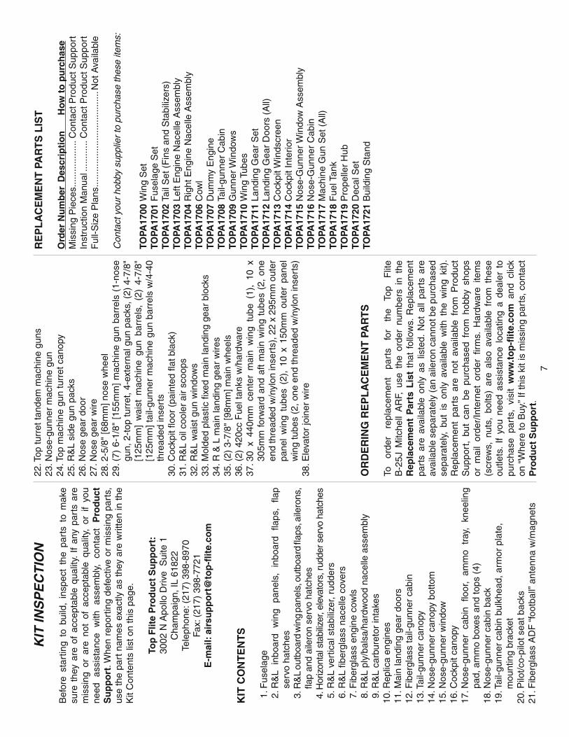
KIT
INS
PE
CT
ION
Bef
ore
star
ting
to b
uild
, in
spec
t th
e pa
rts
to m
ake
sure
the
y ar
e of
acc
epta
ble
qual
ity.
If an
y pa
rts
are
mis
sing
or
are
not
of a
ccep
tabl
e qu
ality
, or
if
you
need
as
sist
ance
w
ith
asse
mbl
y,
cont
act
Pro
du
ct
Su
pp
ort
. Whe
n re
port
ing
defe
ctiv
e or
mis
sing
par
ts,
use
the
part
nam
es e
xact
ly a
s th
ey a
re w
ritte
n in
the
Kit
Con
tent
s lis
t on
this
pag
e.
Top
Flit
e P
rod
uct
Su
pp
ort
:30
02 N
Apo
llo D
rive
Sui
te 1
Cha
mpa
ign,
IL 6
1822
Tele
phon
e: (
217)
398
-897
0Fa
x: (
217)
398
-772
1E
-mai
l: ai
rsu
pp
ort
@to
p-fl
ite.
com
KIT
CO
NT
EN
TS
1. F
usel
age
2. R
&L
inbo
ard
win
g pa
nels
, in
boar
d fl a
ps,
fl ap
serv
o ha
tche
s 3
. R&
L ou
tboa
rd w
ing
pane
ls, o
utbo
ard
fl aps
, aile
rons
, fl a
p an
d ai
lero
n se
rvo
hatc
hes
4. H
oriz
onta
l sta
biliz
er, e
leva
tors
, rud
der s
ervo
hat
ches
5
. R&
L ve
rtic
al s
tabi
lizer
, rud
ders
6. R
&L
fi ber
glas
s na
celle
cov
ers
7. F
iber
glas
s en
gine
cow
ls 8
. R&
L pl
y/ba
lsa/
hard
woo
d na
celle
ass
embl
y 9
. R&
L ca
rbur
etor
inta
kes
10. R
eplic
a en
gine
s11
. Mai
n la
ndin
g ge
ar d
oors
12
. Fib
ergl
ass
tail-
gunn
er c
abin
13. T
ail-g
unne
r ca
nopy
14. N
ose-
gunn
er c
anop
y bo
ttom
15. N
ose-
gunn
er w
indo
w16
. Coc
kpit
cano
py17
. Nos
e-gu
nner
ca
bin
fl oor
, am
mo
tray
, kn
eelin
g pa
d, a
mm
o bo
xes
and
tops
(4)
18. N
ose-
gunn
er c
abin
bac
k19
. Tai
l-gun
ner
cabi
n bu
lkhe
ad, a
rmor
pla
te,
mou
ntin
g br
acke
t20
. Pilo
t/co-
pilo
t sea
t bac
ks21
. Fib
ergl
ass
AD
F “
foot
ball”
ant
enna
w/m
agne
ts
22. T
op tu
rret
tand
em m
achi
ne g
uns
23. N
ose-
gunn
er m
achi
ne g
un24
. Top
mac
hine
gun
turr
et c
anop
y25
. R&
L si
de g
un p
acks
26. N
ose
gear
doo
r27
. Nos
e ge
ar w
ire28
. 2-5
/8"
[68m
m] n
ose
whe
el29
. (7)
6-1
/8"
[155
mm
] m
achi
ne g
un b
arre
ls (
1-no
se
gun,
2-t
op tu
rret
, 4-e
xter
nal g
un p
acks
, (2)
4-7
/8"
[125
mm
] w
aist
mac
hine
gun
bar
rels
, (2
) 4-
7/8"
[1
25m
m] t
ail-g
unne
r m
achi
ne g
un b
arre
ls w
/4-4
0 th
read
ed in
sert
s30
. Coc
kpit
fl oor
(pa
inte
d fl a
t bla
ck)
31. R
&L
oil c
oole
r ai
r sc
oops
32. R
&L
wai
st g
un w
indo
ws
33. M
olde
d pl
astic
fi xe
d m
ain
land
ing
gear
blo
cks
34. R
& L
mai
n la
ndin
g ge
ar w
ires
35. (
2) 3
-7/8
" [9
8mm
] mai
n w
heel
s36
. (2)
420
cc F
uel t
anks
w/h
ardw
are
37. 3
0 x
440m
m c
ente
r m
ain
win
g tu
be (
1),
10 x
30
5mm
for
war
d an
d af
t m
ain
win
g tu
bes
(2,
one
end
thre
aded
w/n
ylon
inse
rts)
, 22
x 29
5mm
out
er
pane
l w
ing
tube
s (2
), 1
0 x
150m
m o
uter
pan
el
win
g tu
bes
(2, o
ne e
nd th
read
ed w
/nyl
on in
sert
s)38
. Ele
vato
r jo
iner
wire
OR
DE
RIN
G R
EP
LA
CE
ME
NT
PA
RT
S
To
orde
r re
plac
emen
t pa
rts
for
the
Top
Flit
e B
-25J
Mitc
hell
AR
F, u
se t
he o
rder
num
bers
in
the
Rep
lace
men
t P
arts
Lis
t th
at f
ollo
ws.
Rep
lace
men
t pa
rts
are
avai
labl
e on
ly a
s lis
ted.
Not
all
part
s ar
e av
aila
ble
sepa
rate
ly (
an a
ilero
n ca
nnot
be
purc
hase
d se
para
tely
, bu
t is
onl
y av
aila
ble
with
the
win
g ki
t).
Rep
lace
men
t pa
rts
are
not
avai
labl
e fr
om P
rodu
ct
Sup
port
, bu
t ca
n be
pur
chas
ed f
rom
hob
by s
hops
or
mai
l or
der/
Inte
rnet
ord
er fi
rm
s. H
ardw
are
item
s (s
crew
s, n
uts,
bol
ts)
are
also
ava
ilabl
e fr
om t
hese
ou
tlets
. If
you
need
ass
ista
nce
loca
ting
a de
aler
to
purc
hase
par
ts,
visi
t w
ww
.to
p-fl
ite.
com
and
clic
k on
“W
here
to B
uy.”
If th
is k
it is
mis
sing
par
ts, c
onta
ct
Pro
du
ct S
up
po
rt.
RE
PL
AC
EM
EN
T P
AR
TS
LIS
T
Ord
er N
um
ber
Des
crip
tio
n
Ho
w t
o p
urc
has
eM
issi
ng P
iece
s ....
......
......
..C
onta
ct P
rodu
ct S
uppo
rtIn
stru
ctio
n M
anua
l ....
......
..C
onta
ct P
rodu
ct S
uppo
rtF
ull-S
ize
Pla
ns ...
......
......
......
......
......
....N
ot A
vaila
ble
Con
tact
you
r ho
bby
supp
lier
to p
urch
ase
thes
e ite
ms:
TOPA
1700
Win
g S
etTO
PA17
01 F
usel
age
Set
TOPA
1702
Tai
l Set
(F
ins
and
Sta
biliz
ers)
TOPA
1703
Lef
t Eng
ine
Nac
elle
Ass
embl
yTO
PA17
04 R
ight
Eng
ine
Nac
elle
Ass
embl
yTO
PA17
06 C
owl
TOPA
1707
Dum
my
Eng
ine
TOPA
1708
Tai
l-gun
ner
Cab
inTO
PA17
09 G
unne
r Win
dow
sTO
PA17
10 W
ing
Tube
sTO
PA17
11 L
andi
ng G
ear
Set
TOPA
1712
Lan
ding
Gea
r D
oors
(A
ll)TO
PA17
13 C
ockp
it W
inds
cree
nTO
PA17
14 C
ockp
it In
terio
rTO
PA17
15 N
ose-
Gun
ner W
indo
w A
ssem
bly
TOPA
1716
Nos
e-G
unne
r C
abin
TOPA
1717
Mac
hine
Gun
Set
(A
ll)TO
PA17
18 F
uel T
ank
TOPA
1719
Pro
pelle
r H
ubTO
PA17
20 D
ecal
Set
TOPA
1721
Bui
ldin
g S
tand
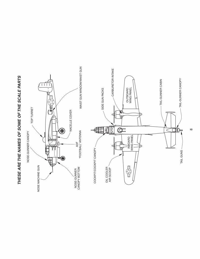
NO
SE
MA
CH
INE
GU
N
NO
SE
-GU
NN
ER
CA
NO
PY
TOP
TU
RR
ET
NA
CE
LLE
CO
VE
R
AD
F“F
OO
TB
ALL
” AN
TE
NN
A
NO
SE
-GU
NN
ER
CA
NO
PY
BO
TTO
M
CO
CK
PIT
/CO
CK
PIT
CA
NO
PY
OIL
CO
OLE
RA
IR S
CO
OP
INB
OA
RD
WIN
G P
AN
EL
OU
TB
OA
RD
WIN
G P
AN
EL
TAIL
-GU
NN
ER
CA
BIN
TAIL
-GU
NN
ER
CA
NO
PY
TAIL
GU
NS
SID
E G
UN
PA
CK
S
CA
RB
UR
ETO
R IN
TAK
E
WA
IST
GU
N W
IND
OW
/WA
IST
GU
N
TH
ES
E A
RE
TH
E N
AM
ES
OF
SO
ME
OF
TH
E S
CA
LE
PA
RT
S
8
9
PR
EPA
RA
TIO
N
PR
EPA
RE
TH
E C
OV
ER
ING
❏ T
ake
time
now
to
tho
rou
gh
ly s
eal
the
cove
ring
to t
he a
irfra
me.
Are
as o
f co
verin
g th
at a
ren’
t bo
nded
to
the
woo
d un
dern
eath
—ev
en i
f yo
u do
n’t
see
any
wrin
kles
now
—m
ay l
oose
n an
d fo
rm w
rinkl
es l
ater
. T
he b
est w
ay to
sea
l dow
n an
d tig
hten
all
the
cove
ring
is t
o us
e a
cove
ring
iron
with
a p
rote
ctiv
e co
verin
g so
ck t
o go
ove
r th
e en
tire
mod
el. P
ush
dow
n on
the
iro
n to
bon
d th
e co
verin
g to
the
woo
d. If
the
cove
ring
bubb
les
you
may
be
usin
g to
o m
uch
heat
or
leav
ing
the
iron
in o
ne p
ositi
on t
oo l
ong.
In
som
e ar
eas,
w
here
the
shee
ting
is s
oft a
nd th
ere
is n
o su
ppor
ting
stru
ctur
e un
dern
eath
, the
she
etin
g m
ay b
end
inw
ard
mak
ing
it di
ffi cu
lt to
rem
ove
the
wrin
kles
in
thos
e ar
eas.
If
this
hap
pens
, us
e le
ss p
ress
ure
on t
he ir
on
or d
on’t
pres
s do
wn
at a
ll. N
ote
: Thi
s pr
oced
ure
take
s tim
e. If
you
don
’t fe
el li
ke g
oing
ove
r th
e en
tire
mod
el
all
at o
nce,
sta
rt w
ith t
he i
nboa
rd w
ing
pane
ls fi
rst
an
d do
the
rest
of t
he p
arts
as
you
need
them
.
AS
SE
MB
LE
TH
E W
ING
PA
NE
LS
HIN
GE
TH
E F
LA
PS
AN
D A
ILE
RO
NS
Dur
ing
cons
truc
tion
ther
e w
ill b
e se
vera
l occ
asio
ns
whe
re e
poxy
cle
anup
will
be
nece
ssar
y. I
nste
ad
of w
astin
g w
hole
pap
er to
wel
s, s
tack
thre
e or
four
pa
per
tow
els
on t
op o
f ea
ch o
ther
and
cut
the
m
into
sm
all s
quar
es. T
his
will
con
serv
e pa
per t
owel
s an
d th
e lit
tle s
quar
es a
re e
asie
r to
use
than
who
le
pape
r to
wel
s. F
or e
poxy
cle
an u
p da
mpe
n th
e sq
uare
s w
ith d
enat
ured
alc
ohol
.
❏ 1
. Tes
t fi t
bot
h in
bo
ard
fl ap
s to
the
in
bo
ard
win
g pa
nels
with
the
lar
ge p
ivot
poi
nt h
inge
s. M
ake
sure
th
e fl a
ps fi
t wel
l and
piv
ot s
moo
thly
.
❏ 2
. Tak
e ou
t the
hin
ges.
Add
a s
mal
l dro
p of
pla
stic
-co
mpa
tible
oil
or a
sm
all d
ab o
f pet
role
um je
lly to
the
pivo
t poi
nt o
f eac
h hi
nge.
Wor
k th
e oi
l int
o ea
ch h
inge
by
piv
otin
g it
back
and
fort
h a
few
tim
es.
❏ 3
. M
ix a
ppro
xim
atel
y 1/
4 oz
. [5
cc]
of 3
0-m
inut
e ep
oxy.
Use
a p
iece
of w
ire to
app
ly e
poxy
into
the
hing
e ho
les
in b
oth
inbo
ard
win
g pa
nels
and
inbo
ard
fl aps
.
❏ 4
. Wip
e of
f an
y ex
cess
epo
xy f
rom
the
out
side
of
all t
he h
inge
hol
es (
usin
g yo
ur p
aper
tow
el s
quar
es).
One
at
a tim
e, a
pply
a t
hin
coat
ing
of e
poxy
to
on
e

10
sid
e of
eac
h hi
nge.
The
n, i
nser
t th
e hi
nges
int
o th
e w
ing.
Whe
n al
l th
e hi
nges
are
in,
wor
king
qui
ckly
, co
at t
he o
ther
end
of
the
hing
es w
ith e
poxy
. T
hen,
jo
in b
oth
fl aps
. Do
your
bes
t to
wip
e aw
ay a
ny e
xces
s ep
oxy.
Mov
e th
e fl a
ps u
p an
d do
wn
seve
ral t
imes
to
alig
n al
l th
e hi
nges
. S
et t
he w
ing
pane
ls a
side
and
al
low
the
epox
y to
har
den.
❏ 6
. Joi
n th
e ou
tboa
rd fl
aps
and
aile
rons
to th
e ou
tboa
rd
win
g pa
nels
the
sam
e w
ay u
sing
fre
sh b
atch
es o
f ep
oxy.
Not
e th
at th
e ai
lero
ns u
se s
mal
l hin
ges.
❏ 7
. Afte
r th
e ep
oxy
on a
ll th
e hi
nges
has
har
dene
d,
mov
e th
e fl a
ps a
nd a
ilero
ns u
p an
d do
wn
seve
ral
times
to g
et th
em m
ovin
g sm
ooth
ly a
nd e
asily
.
We’
ll in
stal
l th
e se
rvos
and
hoo
k up
the
fl a
ps a
nd
aile
rons
late
r.
MO
UN
T T
HE
EN
GIN
ES
❏ 1
. Use
med
ium
CA
or
epox
y to
glu
e tw
o 8
x 30
mm
gr
oove
d ny
lon
alig
nmen
t pe
gs
into
th
e ho
les
in
each
eng
ine
nace
lle.
Be
cert
ain
the
peg
indi
cate
d pr
otru
des
abov
e th
e ba
se o
f the
nac
elle
app
roxi
mat
ely
3/4"
[19m
m].
❏ ❏
2.
Afte
r th
e ep
oxy
from
the
pre
viou
s st
ep h
as
hard
ened
, us
e fo
ur 1
/4-2
0 x
2" [
50m
m]
nylo
n bo
lts
(indi
cate
d by
the
arr
ows
in t
he p
hoto
) to
mou
nt t
he
left
eng
ine
nace
lle t
o th
e bo
ttom
of
the
left
inbo
ard
win
g pa
nel.
❏ ❏
3. R
ead
the
note
fol
low
ing
this
ste
p. T
hen,
cut
ou
t the
left
En
gin
e M
ou
nti
ng
Tem
pla
te (
sinc
e w
e’re
do
ing
the
left
nace
lle fi
rst)
from
the
back
of t
he m
anua
l fo
r th
e ty
pe o
f en
gine
you
will
be
usin
g—tw
o-st
roke
or
four
-str
oke.
Use
tape
or
spra
y ad
hesi
ve to
hol
d th
e te
mpl
ate
to th
e fi r
ewal
l. T
hen
use
a sh
arpe
ned
piec
e of
wire
or a
larg
e T-
pin
to m
ark
the
cent
er o
f the
hol
es
in th
e te
mpl
ate
into
the
fi rew
all.
No
te: T
he fo
ur-s
trok
e te
mpl
ate
is fo
r the
O.S
. Max
.70
Sur
pass
and
the
tw
o-st
roke
tem
plat
e is
for
an
O.S
. M
ax .
40 o
r .5
0 tw
o-st
roke
. Sin
ce t
he e
ngin
e m
ount
s ar
e ad
just
able
, th
ey s
houl
d fi t
oth
er e
ngin
es i
n th
e si
ze r
ange
, but
if y
ou a
re u
sing
eng
ines
diff
eren
t tha
n O
.S.
the
posi
tioni
ng o
f th
e m
ount
s m
ay h
ave
to b
e ro
tate
d sl
ight
ly t
o al
ign
the
muf
fl er
with
the
muf
fl er
cuto
ut i
n th
e fi b
ergl
ass
nace
lle c
over
. If
this
is
the
case
, yo
u’ll
have
to
mou
nt y
our
engi
ne t
o th
e m
ount
be
fore
mar
king
the
hol
es in
the
fi r
ewal
l. T
hen,
pla
ce
the
nace
lle c
over
ove
r th
e na
celle
on
the
win
g pa
nel
and
posi
tion
the
mou
nt
(with
th
e en
gine
) so
th
e m
uffl e
r fi t
s in
the
muf
fl er
cuto
ut.
❏ ❏
4.
Onc
e th
e en
gine
mou
nt h
oles
hav
e be
en
mar
ked,
dril
l 5/
32"
[4m
m]
hole
s th
roug
h th
e fi r
ewal
l at
eac
h m
ark.
Rem
ove
the
tem
plat
e. P
ush
4-40
blin
d nu
ts i
nto
the
hole
s in
the
bac
k of
the
fi r
ewal
l—if
nece
ssar
y, tr
im a
way
any
ply
woo
d th
at in
terf
eres
with
th
e bl
ind
nuts
.
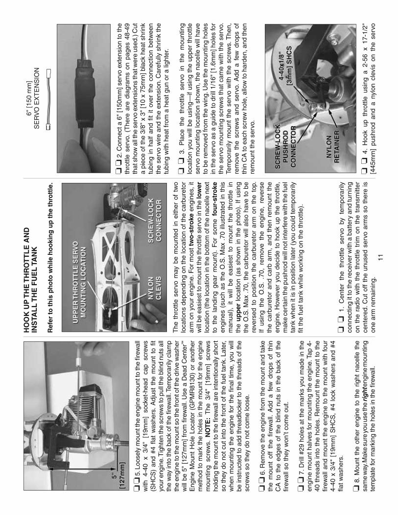
11
❏ ❏
5. L
oose
ly m
ount
the
engi
ne m
ount
to th
e fi r
ewal
l w
ith
4-40
x
3/4"
[1
9mm
] so
cket
-hea
d ca
p sc
rew
s (S
HC
S)
and
#4 fl
at
was
hers
. A
djus
t th
e m
ount
to
fi t
your
eng
ine.
Tig
hten
the
scre
ws
to p
ull t
he b
lind
nuts
all
the
way
into
the
back
of t
he fi
rew
all.
Tem
pora
rily
clam
p th
e en
gine
to th
e m
ount
so
the
fron
t of t
he d
rive
was
her
will
be
5" [1
27m
m] f
rom
fi re
wal
l. U
se a
Dea
d C
ente
r™
Eng
ine
Mou
nt H
ole
Loca
tor
(GP
MR
8130
) or
ano
ther
m
etho
d to
mar
k th
e ho
les
in th
e m
ount
for
the
engi
ne
mou
ntin
g sc
rew
s. N
OT
E:
The
3/4
" [1
9mm
] sc
rew
s ho
ldin
g th
e m
ount
to th
e fi r
ewal
l are
inte
ntio
nally
sho
rt
so th
ey d
o no
t cut
into
the
fron
t of t
he fu
el ta
nk. L
ater
, w
hen
mou
ntin
g th
e en
gine
for
the
fi n
al t
ime,
you
will
be
inst
ruct
ed to
add
thre
adlo
cker
to th
e th
read
s of
the
scre
ws
so th
ey d
o no
t com
e lo
ose.
❏ ❏
6. R
emov
e th
e en
gine
from
the
mou
nt a
nd ta
ke
the
mou
nt o
ff th
e fi r
ewal
l. A
dd a
few
dro
ps o
f th
in
CA
to
the
edge
s of
the
blin
d nu
ts in
the
bac
k of
the
fi r
ewal
l so
they
won
’t co
me
out.
❏ ❏
7. D
rill #
29 h
oles
at t
he m
arks
you
mad
e in
the
engi
ne m
ount
hal
ves
for
mou
ntin
g th
e en
gine
. Tap
4-
40 t
hrea
ds in
to t
he h
oles
. Rem
ount
the
mou
nt t
o th
e fi r
ewal
l and
mou
nt t
he e
ngin
e to
the
mou
nt w
ith fo
ur
4-40
x 3
/4"
[19m
m]
SH
CS
, #4
loc
k w
ashe
rs a
nd #
4 fl a
t was
hers
.
❏ 8
. Mou
nt t
he o
ther
eng
ine
to t
he r
ight
nac
elle
the
sa
me
way
. Mak
e su
re y
ou u
se th
e ri
gh
t eng
ine
mou
ntin
g te
mpl
ate
for
mar
king
the
hole
s in
the
fi rew
all.
HO
OK
UP
TH
E T
HR
OT
TL
E A
ND
INS
TAL
L T
HE
FU
EL
TA
NK
Ref
er t
o t
his
ph
oto
wh
ile h
oo
kin
g u
p t
he
thro
ttle
.
The
thr
ottle
ser
vo m
ay b
e m
ount
ed i
n ei
ther
of
two
loca
tions
dep
endi
ng o
n th
e lo
catio
n of
the
carb
uret
or
arm
on
your
eng
ine.
For
mos
t tw
o-s
tro
ke e
ngin
es, i
t w
ill b
e ea
sies
t to
mou
nt th
e th
rottl
e se
rvo
in th
e lo
wer
lo
catio
n (t
he lo
catio
n in
the
botto
m o
f the
nac
elle
nex
t to
the
lan
ding
gea
r m
ount
). F
or s
ome
fou
r-st
roke
en
gine
s (s
uch
as t
he O
.S. M
ax .
70 il
lust
rate
d in
thi
s m
anua
l), i
t w
ill b
e ea
sies
t to
mou
nt t
he t
hrot
tle i
n th
e u
pp
er lo
catio
n (a
s sh
own
in t
he p
hoto
). If
usin
g th
e O
.S. M
ax .
70,
the
carb
uret
or w
ill a
lso
have
to
be
reve
rsed
to
posi
tion
the
carb
uret
or a
rm o
n th
e to
p.
If us
ing
the
O.S
. .7
0, r
emov
e th
e en
gine
, re
vers
e th
e ca
rbur
etor
and
car
b ar
m,
and
then
rem
ount
the
en
gine
. How
ever
you
dec
ide
to h
ook
up t
he t
hrot
tle,
mak
e ce
rtai
n th
e pu
shro
d w
ill n
ot in
terf
ere
with
the
fuel
ta
nk w
hen
it is
in p
ositi
on la
ter
(you
cou
ld te
mpo
raril
y fi t
the
fuel
tank
whi
le w
orki
ng o
n th
e th
rottl
e).
❏ ❏
1.
Cen
ter
the
thro
ttle
serv
o by
tem
pora
rily
conn
ectin
g it
to th
e re
ceiv
er w
ith a
bat
tery
and
turn
ing
on t
he r
adio
with
the
thr
ottle
trim
on
the
tran
smitt
er
cent
ered
. Cut
off
the
unus
ed s
ervo
arm
s so
the
re is
on
e ar
m r
emai
ning
.
6" [1
50 m
m]
SE
RV
O E
XT
EN
SIO
N
❏ ❏
2. C
onne
ct a
6"
[150
mm
] ser
vo e
xten
sion
to th
e th
rottl
e se
rvo.
(T
here
are
dia
gram
s on
pag
es 4
8-49
th
at s
how
all
the
serv
o ex
tens
ions
that
wer
e us
ed.)
Cut
a
piec
e of
the
3/8"
x 3
" [1
0 x
75m
m] b
lack
hea
t shr
ink
tubi
ng i
n ha
lf an
d fi t
it
over
the
con
nect
ion
betw
een
the
serv
o w
ire a
nd th
e ex
tens
ion.
Car
eful
ly s
hrin
k th
e tu
bing
with
hea
t fro
m a
hea
t gun
or
a lig
hter
.
❏ ❏
3.
Pla
ce t
he t
hrot
tle s
ervo
in
the
mou
ntin
g lo
catio
n yo
u w
ill b
e us
ing—
if us
ing
the
uppe
r th
rottl
e se
rvo
mou
ntin
g lo
catio
n sh
own,
the
nace
lle w
ill h
ave
to b
e re
mov
ed fr
om th
e w
ing.
Use
the
mou
ntin
g ho
les
in th
e se
rvo
as a
gui
de to
dril
l 1/1
6" [1
.6m
m] h
oles
for
the
serv
o m
ount
ing
scre
ws
that
cam
e w
ith th
e se
rvo.
Te
mpo
raril
y m
ount
the
ser
vo w
ith t
he s
crew
s. T
hen,
re
mov
e th
e sc
rew
s an
d se
rvo.
Add
a f
ew d
rops
of
thin
CA
to e
ach
scre
w h
ole,
allo
w to
har
den,
and
then
re
mou
nt th
e se
rvo.
❏ ❏
4.
Hoo
k up
thr
ottle
usi
ng a
2-5
6 x
17-1
/2"
[445
mm
] pu
shro
d an
d a
nylo
n cl
evis
on
the
serv
o

12
end
and
a br
ass
scre
w-lo
ck c
onne
ctor
with
a n
ylon
re
tain
er a
nd a
4-4
0 x
1/8"
[3m
m]
sock
et-h
ead
cap
scre
w (S
HC
S) o
n th
e ca
rbur
etor
arm
. Cut
a s
lot i
n th
e fi r
ewal
l for
the
thro
ttle
push
rod.
Ben
d th
e pu
shro
d as
ne
cess
ary
to c
onne
ct to
the
carb
uret
or a
rm.
❏ ❏
6.
For
ins
talli
ng t
he f
uel
tank
, m
ount
ing
the
fi ber
glas
s na
celle
cov
er a
nd m
ount
ing
the
land
ing
gear
, it
will
be
easi
er t
o ha
ve t
he e
ngin
e ou
t of
the
w
ay. R
emov
e th
e en
gine
mou
nt fr
om th
e fi r
ewal
l and
se
t the
eng
ine
asid
e.
❏ ❏
7. A
ssem
ble
both
fuel
tank
s—a
thre
e-lin
e se
tup
is re
com
men
ded—
one
for t
he v
ent/p
ress
ure
line
goin
g to
the
muf
fl er,
one
for f
uel p
icku
p to
the
carb
uret
or a
nd
a th
ird li
ne f
or f
uelin
g/de
fuel
ing.
Thi
s se
tup
will
allo
w
fuel
ing
and
defu
elin
g w
ithou
t ha
ving
to
disc
onne
ct
any
lines
fro
m t
he c
arbu
reto
r an
d w
ithou
t ha
ving
to
turn
the
mod
el u
psid
e-do
wn.
To
set
up t
he f
uel t
ank
this
way
, cut
two
of th
e al
umin
um tu
bes
to a
leng
th o
f 1-
3/8"
[35m
m] a
nd le
ave
the
othe
r, lo
nger
tube
as-
is.
Ass
embl
e th
e st
oppe
r as
sem
bly
with
the
alu
min
um
tube
s, b
end
the
long
er v
ent
tube
upw
ard
so it
will
be
at t
he t
op o
f th
e ta
nk,
and
then
cut
the
sili
cone
line
s to
the
corr
ect l
engt
h so
the
clun
ks w
ill n
ot c
onta
ct th
e re
ar o
f the
tank
. Con
nect
the
lines
to th
e tu
bes
in th
e st
oppe
r an
d fi t
the
sto
pper
into
the
tan
k an
d tig
hten
th
e sc
rew
. M
ake
sure
the
clu
nks
do n
ot c
onta
ct t
he
rear
of t
he ta
nk; o
ther
wis
e, th
ey c
ould
get
stu
ck.
❏ ❏
8. M
ount
the
left
nace
lle to
the
win
g w
ith th
e ny
lon
bolts
. Fit
the
fuel
tank
into
the
nace
lle. T
hen,
inst
all a
nd
glue
two
3/8"
x 3
-1/1
6" [1
0 x
78m
m] p
lyw
ood
fuel
tan
k st
icks
from
the
lase
r-cu
t ply
woo
d sh
eet i
nto
the
slot
s to
hol
d th
e fu
el ta
nk in
pos
ition
. No
te: E
ven
thou
gh fu
el
lines
app
ear
in a
few
of
the
follo
win
g ph
otos
, th
ere’
s no
nee
d to
con
nect
them
unt
il la
ter
afte
r th
e co
wl h
as
been
mou
nted
—th
e m
anua
l will
inst
ruct
you
late
r.
❏ 9
. Ret
urn
to s
tep
1 an
d m
ount
the
engi
ne, h
ook
up
the
thro
ttle
and
inst
all t
he fu
el ta
nk in
the
right
nac
elle
th
e sa
me
way
.
MO
UN
T T
HE
MA
IN L
AN
DIN
G G
EA
R
RE
TR
AC
T IN
STA
LL
AT
ION
(If
no
t m
ou
nti
ng
ret
ract
s, s
kip
to
“F
ixed
Gea
r In
stal
lati
on
” o
n t
he
nex
t p
age.
)
Sam
e as
we’
ve b
een
doin
g so
far,
star
t w
ith t
he le
ft,
inbo
ard
win
g pa
nel.
❏ ❏
1. D
eter
min
e w
hich
col
or o
f ai
r lin
e yo
u w
ill b
e us
ing
for
the
“up”
lin
e an
d w
hich
col
or y
ou w
ill b
e us
ing
for
the
“dow
n” li
ne—
the
up li
ne c
onne
cts
to th
e fi t
ting
on th
e ba
ck e
nd o
f the
air
cylin
der a
nd th
e do
wn
line
conn
ects
to th
e fi t
ting
on th
e fr
ont o
f the
cyl
inde
r th
at c
omes
out
of t
he s
ide.
Cut
the
up li
ne to
a le
ngth
of
21"
[53
0mm
] an
d cu
t th
e do
wn
line
to a
leng
th o
f 18
" [4
60m
m].
❏ ❏
2. C
onne
ct t
he li
nes
to t
he a
ir cy
linde
r. R
otat
e th
e fi t
ting
on t
he d
own
line
as s
how
n so
it
will
be
easi
er to
fi t t
he g
ear
betw
een
the
rails
.
❏ ❏
3. I
nsta
ll th
e re
tract
and
gui
de th
e ai
r lin
es th
roug
h th
e ho
le in
the
botto
m o
f the
pan
el, p
ast t
he fl
ap s
ervo
ha
tch
and
out r
oot e
nd o
f the
pan
el—
note
that
the
up li
ne
goes
thro
ugh
the
hole
in th
e ba
ck o
f the
nac
elle
fi rs
t.

13
❏ ❏
4. H
oldi
ng th
e re
trac
t cen
tere
d in
the
rails
with
th
e st
rut r
etra
cted
so
it w
ill b
e ou
t of t
he w
ay, d
rill f
our
7/64
" [2
.8m
m]
hole
s fo
r th
e m
ount
ing
scre
ws.
Mou
nt
the
retr
act w
ith fo
ur #
6 x
1/2"
[13m
m] P
hilli
ps s
crew
s.
❏ ❏
5. U
se a
rota
ry to
ol w
ith a
fi be
r-re
info
rced
cut
off
whe
el t
o cu
t th
e on
e of
the
mai
n la
ndin
g ge
ar a
xles
th
at c
ame
with
the
ret
ract
s to
the
cor
rect
leng
th. F
ile
a fl a
t sp
ot o
n th
e ax
le f
or t
he s
et s
crew
tha
t m
ount
s th
e ax
le t
o th
e st
rut.
Mou
nt t
he w
heel
with
a d
rop
of
thre
adlo
cker
on
the
set
scre
w.
Add
a d
rop
of o
il to
bo
th s
ides
of t
he w
heel
at t
he s
trut
and
the
axle
.
❏ 6
. Mou
nt th
e ot
her
retr
act t
o th
e rig
ht in
boar
d w
ing
pane
l the
sam
e w
ay.
FIX
ED
GE
AR
INS
TAL
LA
TIO
N
❏ ❏
1.
Ass
embl
e on
e of
the
lan
ding
gea
r m
ount
s by
usi
ng e
ight
3 x
12m
m fl
at-h
ead
Phi
llips
scr
ews
to
mou
nt a
n al
umin
um m
ount
ing
brac
ket t
o ea
ch s
ide
of
one
of th
e m
olde
d pl
astic
mai
n la
ndin
g ge
ar b
lock
s.
Ref
er to
this
pho
to w
hile
mou
ntin
g th
e la
ndin
g ge
ar.
❏ ❏
2.
Cen
ter
the
land
ing
gear
m
ount
on
th
e m
ount
ing
rails
. The
n, d
rill f
our 7
/64"
[2.8
mm
] hol
es fo
r th
e m
ount
ing
scre
ws.
Mou
nt t
he la
ndin
g ge
ar m
ount
w
ith fo
ur #
6 x
1/2"
[13m
m] P
hilli
ps s
crew
s.
❏ ❏
3. M
ount
the
left,
mai
n la
ndin
g ge
ar w
ire in
to th
e la
ndin
g ge
ar m
ount
usi
ng tw
o ny
lon
stra
ps a
nd fo
ur #
4 x
1/2"
[13m
m] s
crew
s. M
ount
one
of t
he m
ain
whe
els
to t
he la
ndin
g ge
ar w
ire w
ith t
wo
5mm
whe
el c
olla
rs
and
6-32
set
scr
ews
with
thre
adlo
cker
on
the
thre
ads.
❏ 4
. Mou
nt th
e ot
her l
andi
ng g
ear t
o th
e rig
ht in
boar
d w
ing
pane
l th
e sa
me
way
. A
dd a
dro
p of
oil
to b
oth
side
s of
the
whe
els
whe
re th
ey c
onta
ct th
e co
llars
.
MO
UN
T TH
E F
IBE
RG
LAS
S N
AC
ELL
E C
OV
ER
S
❏ ❏
1. I
f you
hav
en’t
done
so
alre
ady,
rem
ove
the
left
engi
ne f
rom
the
eng
ine
mou
nt s
o th
e na
celle
cov
er
will
fi t o
ver
the
nace
lle. P
lace
the
left
fi ber
glas
s na
celle
co
ver
over
the
nac
elle
on
the
win
g. U
se a
pus
hrod
sh
arpe
ned
on th
e en
d or
a D
ead
Cen
ter™
Eng
ine
Mou
nt
Hol
e Lo
cato
r to
mar
k th
e lo
catio
n of
the
thre
e m
ount
ing
scre
ws
for t
he n
acel
le c
over
into
the
botto
m o
f the
win
g.
❏ ❏
2. R
emov
e th
e na
celle
cov
er. D
rill 3
/32"
[2.4
mm
] ho
les
into
the
win
g at
the
mar
ks.
Enl
arge
the
hol
es
in t
he p
lyw
ood
mou
ntin
g ta
bs i
n t
he
nac
elle
cov
er
on
ly w
ith a
1/8
" [3
.2m
m]
drill
. Use
a lo
ng #
1 P
hilli
ps
scre
wdr
iver
to te
mpo
raril
y m
ount
the
nace
lle c
over
to
the
win
g w
ith f
our
#4 x
5/8
" [1
6mm
] P
hilli
ps s
crew
s,
#4 fl
at w
ashe
rs a
nd #
4 lo
ck w
ashe
rs.
❏ ❏
3. R
emov
e th
e na
celle
cov
er. A
dd a
few
dro
ps
of t
hin
CA
to
each
of
the
scre
w h
oles
for
the
nac
elle
co
ver m
ount
ing
scre
ws.
Allo
w th
e C
A to
har
den
befo
re
mou
ntin
g th
e na
celle
cov
er b
ack
to th
e w
ing.
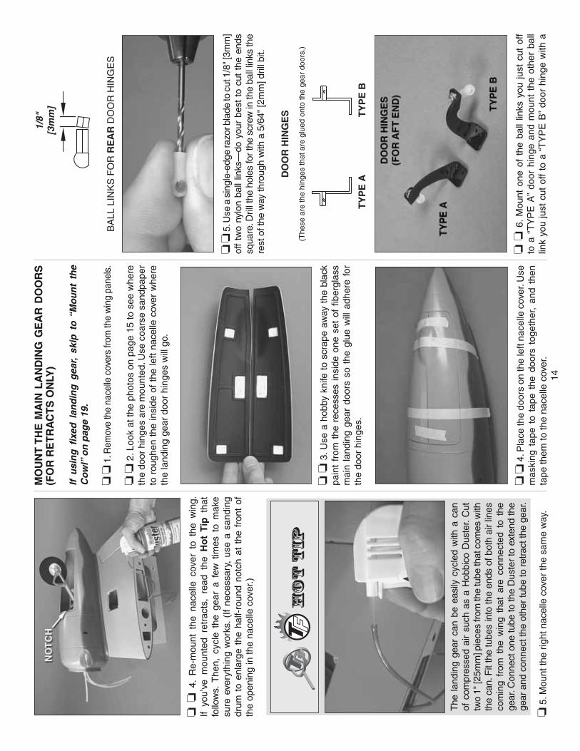
14
❏ ❏
4.
Re-
mou
nt t
he n
acel
le c
over
to
the
win
g.
If yo
u’ve
mou
nted
ret
ract
s, r
ead
the
Ho
t T
ip t
hat
follo
ws.
The
n, c
ycle
the
gea
r a
few
tim
es t
o m
ake
sure
eve
ryth
ing
wor
ks.
(If
nece
ssar
y, u
se a
san
ding
dr
um t
o en
larg
e th
e ha
lf-ro
und
notc
h at
the
fro
nt o
f th
e op
enin
g in
the
nace
lle c
over
.)
The
lan
ding
gea
r ca
n be
eas
ily c
ycle
d w
ith a
can
of
com
pres
sed
air
such
as
a H
obbi
co D
uste
r. C
ut
two
1" [2
5mm
] pie
ces
from
the
tube
that
com
es w
ith
the
can.
Fit
the
tube
s in
to th
e en
ds o
f bot
h ai
r lin
es
com
ing
from
the
win
g th
at a
re c
onne
cted
to
the
gear
. Con
nect
one
tube
to th
e D
uste
r to
ext
end
the
gear
and
con
nect
the
othe
r tu
be to
ret
ract
the
gear
.
❏ 5
. Mou
nt th
e rig
ht n
acel
le c
over
the
sam
e w
ay.
MO
UN
T T
HE
MA
IN L
AN
DIN
G G
EA
R D
OO
RS
(F
OR
RE
TR
AC
TS
ON
LY)
If u
sin
g fi
xed
lan
din
g g
ear,
skip
to
“M
ou
nt
the
Co
wl”
on
pag
e 19
.
❏ ❏
1. R
emov
e th
e na
celle
cov
ers
from
the
win
g pa
nels
.
❏ ❏
2. L
ook
at th
e ph
otos
on
page
15
to s
ee w
here
th
e do
or h
inge
s ar
e m
ount
ed. U
se c
oars
e sa
ndpa
per
to r
ough
en t
he in
side
of
the
left
nace
lle c
over
whe
re
the
land
ing
gear
doo
r hi
nges
will
go.
❏ ❏
3. U
se a
hob
by k
nife
to
scra
pe a
way
the
bla
ck
pain
t fr
om t
he r
eces
ses
insi
de o
ne s
et o
f fi b
ergl
ass
mai
n la
ndin
g ge
ar d
oors
so
the
glue
will
adh
ere
for
the
door
hin
ges.
❏ ❏
4. P
lace
the
door
s on
the
left
nace
lle c
over
. Use
m
aski
ng t
ape
to t
ape
the
door
s to
geth
er,
and
then
ta
pe th
em to
the
nace
lle c
over
.
1/8"
[3m
m]
BA
LL L
INK
S F
OR
RE
AR
DO
OR
HIN
GE
S
❏ ❏
5. U
se a
sin
gle-
edge
razo
r bla
de to
cut
1/8
" [3m
m]
off
two
nylo
n ba
ll lin
ks—
do y
our
best
to
cut
the
ends
sq
uare
. Dril
l the
hol
es fo
r the
scr
ew in
the
ball
links
the
rest
of t
he w
ay th
roug
h w
ith a
5/6
4" [2
mm
] dril
l bit.
(The
se a
re th
e hi
nges
that
are
glu
ed o
nto
the
gear
doo
rs.)
DO
OR
HIN
GE
S
TY
PE
AT
YP
E B
❏ ❏
6.
Mou
nt o
ne o
f th
e ba
ll lin
ks y
ou j
ust
cut
off
to a
“T
YP
E A
” do
or h
inge
and
mou
nt t
he o
ther
bal
l lin
k yo
u ju
st c
ut o
ff to
a “
TY
PE
B”
door
hin
ge w
ith a
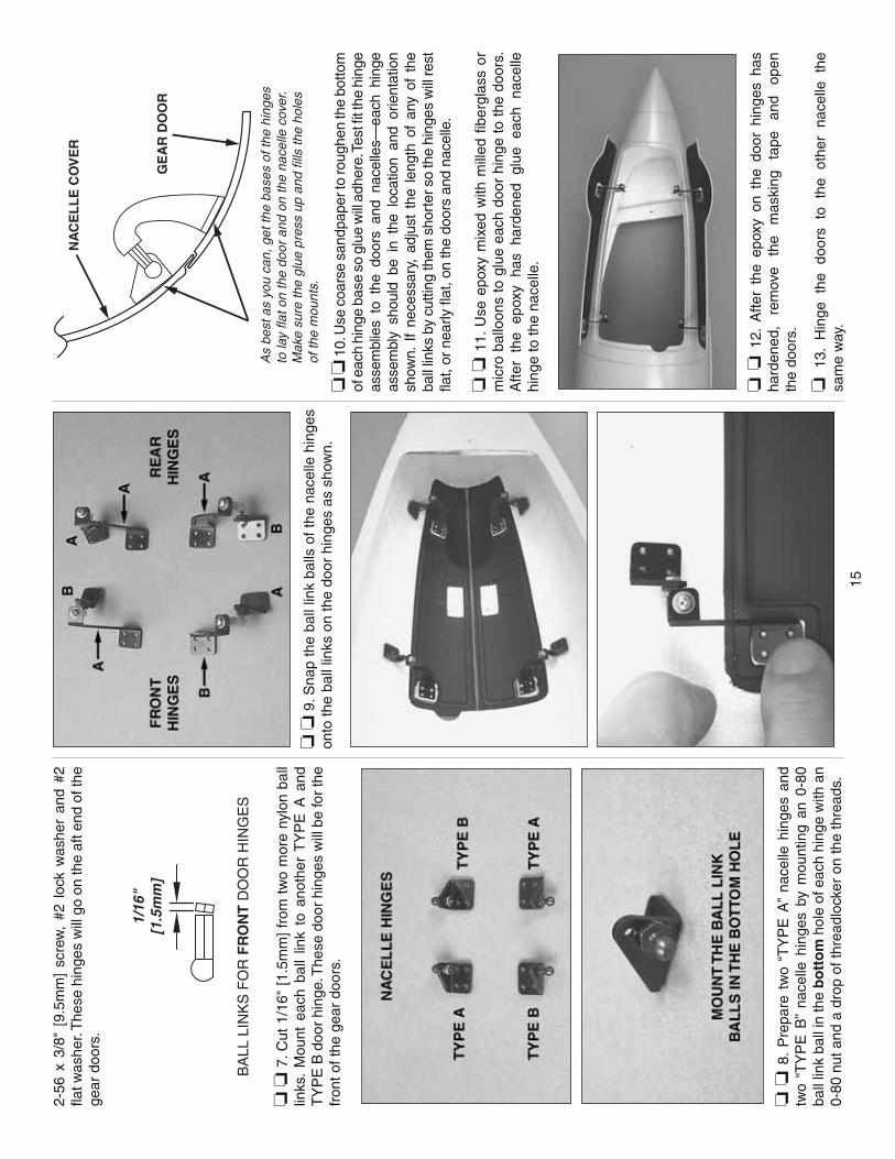
15
2-56
x 3
/8"
[9.5
mm
] sc
rew
, #2
loc
k w
ashe
r an
d #2
fl a
t was
her.
The
se h
inge
s w
ill g
o on
the
aft e
nd o
f the
ge
ar d
oors
.
1/16
"[1
.5m
m]
BA
LL L
INK
S F
OR
FR
ON
T D
OO
R H
ING
ES
❏ ❏
7. C
ut 1
/16"
[1.
5mm
] fr
om t
wo
mor
e ny
lon
ball
links
. M
ount
eac
h ba
ll lin
k to
ano
ther
TY
PE
A a
nd
TY
PE
B d
oor
hing
e. T
hese
doo
r hi
nges
will
be
for
the
fron
t of t
he g
ear
door
s.
❏ ❏
8.
Pre
pare
tw
o “T
YP
E A
” na
celle
hin
ges
and
two
“TY
PE
B”
nace
lle h
inge
s by
mou
ntin
g an
0-8
0 ba
ll lin
k ba
ll in
the
bo
tto
m h
ole
of e
ach
hing
e w
ith a
n 0-
80 n
ut a
nd a
dro
p of
thre
adlo
cker
on
the
thre
ads.
❏ ❏
9. S
nap
the
ball
link
balls
of t
he n
acel
le h
inge
s on
to th
e ba
ll lin
ks o
n th
e do
or h
inge
s as
sho
wn.
As
best
as
you
can,
get
the
base
s of
the
hing
esto
lay
flat o
n th
e do
or a
nd o
n th
e na
celle
cov
er.
Mak
e su
re th
e gl
ue p
ress
up
and
fills
the
hole
sof
the
mou
nts.
NA
CE
LL
E C
OV
ER
GE
AR
DO
OR
❏ ❏
10.
Use
coa
rse
sand
pape
r to
roug
hen
the
botto
m
of e
ach
hing
e ba
se s
o gl
ue w
ill a
dher
e. T
est fi
t th
e hi
nge
asse
mbl
ies
to t
he d
oors
and
nac
elle
s—ea
ch h
inge
as
sem
bly
shou
ld b
e in
the
loc
atio
n an
d or
ient
atio
n sh
own.
If
nece
ssar
y, a
djus
t th
e le
ngth
of
any
of t
he
ball
links
by
cutti
ng th
em s
hort
er s
o th
e hi
nges
will
rest
fl a
t, or
nea
rly fl
at, o
n th
e do
ors
and
nace
lle.
❏ ❏
11.
Use
epo
xy m
ixed
with
mill
ed fi
ber
glas
s or
m
icro
bal
loon
s to
glu
e ea
ch d
oor
hing
e to
the
doo
rs.
Afte
r th
e ep
oxy
has
hard
ened
glu
e ea
ch n
acel
le
hing
e to
the
nace
lle.
❏ ❏
12.
Afte
r th
e ep
oxy
on t
he d
oor
hing
es h
as
hard
ened
, re
mov
e th
e m
aski
ng
tape
an
d op
en
the
door
s.
❏ 1
3.
Hin
ge
the
door
s to
th
e ot
her
nace
lle
the
sam
e w
ay.
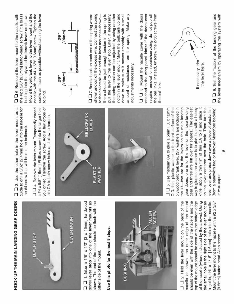
16
HO
OK
UP
TH
E M
AIN
LA
ND
ING
GE
AR
DO
OR
S
❏ ❏
1.
Glu
e a
1/8"
x 1
/2"
[3 x
15m
m]
hard
woo
d do
wel
lev
er s
top
int
o on
e of
the
lev
er m
ou
nts
as
show
n. T
he e
nd o
f th
e st
op s
houl
d be
fl us
h w
ith t
he
othe
r si
de o
f the
mou
nt.
Use
th
is p
ho
to fo
r th
e n
ext
8 st
eps.
❏ ❏
2.
Hol
d th
e le
ver
mou
nt o
n th
e ba
ck o
f th
e na
celle
as
sh
own—
the
oute
r ed
ge
of
the
mou
nt
shou
ld b
e ev
en w
ith t
he s
ide
of t
he n
acel
le a
nd t
he
top
of th
e m
ount
sho
uld
be e
ven
with
the
botto
m e
dge
of th
e na
celle
(w
here
indi
cate
d by
the
arro
ws)
. Usi
ng
the
smal
l hol
e in
the
rig
ht s
ide
of t
he le
ver
mou
nt a
s a
guid
e, d
rill
a 1/
16"
[1.6
mm
] ho
le i
nto
the
nace
lle.
Mou
nt th
e le
ver
mou
nt to
the
nace
lle w
ith a
#2
x 3/
8"
[9.5
mm
] but
ton-
head
Alle
n sc
rew
.
❏ ❏
3.
Use
the
oth
er h
ole
in t
he l
ever
mou
nt a
s a
guid
e to
dril
l a 3
/32"
[2.4
mm
] hol
e in
to th
e na
celle
for
the
#4 s
crew
that
will
hol
d in
the
bellc
rank
.
❏ ❏
4. R
emov
e th
e le
ver
mou
nt. T
empo
raril
y th
read
a
#4 x
5/8
" [1
6mm
] Phi
llips
scr
ew in
to th
e la
rger
hol
e yo
u dr
illed
. R
emov
e th
e sc
rew
. A
dd a
few
dro
ps o
f th
in C
A to
bot
h sc
rew
hol
es a
nd a
llow
to h
arde
n.
❏ ❏
5. U
se m
ediu
m C
A to
glu
e a
5mm
I.D
. x 1
2mm
O
.D.
thin
, pl
astic
was
her
to t
he f
ront
sur
face
of
the
plyw
ood
bellc
rank
leve
r. (S
ix w
ashe
rs a
re in
clud
ed in
th
e ki
t—tw
o ar
e fo
r th
e le
vers
on
the
mai
n la
ndin
g ge
ar d
oors
, on
e is
for
the
leve
r on
the
nos
e la
ndin
g ge
ar a
nd t
hree
are
left
over
for
spa
res.
) T
he e
asie
st
way
to g
lue
on th
e w
ashe
r is
to p
ick
it up
with
a h
obby
kn
ife,
appl
y a
thin
fi lm
of
thin
CA
to
it an
d pl
ace
it on
the
lev
er c
ente
red
over
the
hol
e. T
hen
turn
the
le
ver
over
and
pre
ss d
own
over
a p
iece
of p
last
ic fi
lm
(fro
m a
san
dwic
h ba
g or
lefto
ver
Mon
oKot
e ba
ckin
g)
or w
ax p
aper
.
❏ ❏
6. R
emou
nt th
e le
ver
mou
nt to
the
nace
lle w
ith
the
#2 x
3/8
" [9
.5m
m] b
utto
n-he
ad s
crew
. Fit
a br
ass
bush
ing
into
the
ply
woo
d b
ellc
ran
k le
ver
as s
how
n.
Mou
nt t
he b
ellc
rank
leve
r to
the
leve
r m
ount
and
the
na
celle
with
the
#4
x 5/
8" [
16m
m]
scre
w. T
ight
en t
he
scre
w a
s m
uch
as p
ossi
ble
with
out c
ausi
ng th
e le
ver
to b
ind.
3/8"
[10m
m]
3/8"
[10m
m]
❏ ❏
7. B
end
a ho
ok o
n ea
ch e
nd o
f the
spr
ing
whe
re
show
n an
d cu
t off
the
exce
ss w
ire. C
onne
ct th
e sp
ring
to th
e be
llcra
nk le
ver a
nd th
e le
ver m
ount
as
show
n—th
ere
shou
ld b
e ju
st e
noug
h te
nsio
n in
the
spr
ing
to
pull
the
leve
r to
the
lev
er s
top.
Lat
er,
if ne
cess
ary,
th
e sp
ring
tens
ion
can
be a
djus
ted
by u
sing
ano
ther
no
tch
in t
he le
ver
mou
nt. M
ove
the
bellc
rank
up
and
dow
n to
mak
e su
re i
t m
oves
sm
ooth
ly w
ith a
sm
all
amou
nt
of
resi
stan
ce
from
th
e sp
ring.
M
ake
any
adju
stm
ents
nec
essa
ry.
❏ ❏
8.
Mou
nt t
he n
acel
le c
over
with
the
doo
rs
atta
ched
to
the
win
g pa
nel.
No
te:
If th
e do
ors
ever
re
quire
rem
oval
for
rep
airs
/ser
vici
ng,
do n
ot p
op o
ff th
e ba
ll lin
ks. I
nste
ad, u
nscr
ew th
e 2-
56 s
crew
s fr
om
the
ball
links
.
If ne
cess
ary,
trim
the
leve
r he
re.
❏ ❏
9.
Test
the
“ac
tion”
of
the
land
ing
gear
and
th
e le
ver
mec
hani
sm b
y op
erat
ing
the
syst
em w
ith

17
com
pres
sed
air.
Mak
e su
re t
he g
ear
lock
s at
bot
h en
ds—
up a
nd d
own.
It
may
be
nece
ssar
y to
slig
htly
tr
im t
he le
ver
to a
llow
the
land
ing
gear
str
ut t
o m
ove
free
ly.
If ne
cess
ary,
rem
ove
the
leve
r, tr
im,
rein
stal
l an
d te
st.
❏ ❏
10.
Use
coa
rse
sand
pape
r to
rou
ghen
the
m
ount
ing
base
of
tw
o sm
all
nylo
n co
ntro
l ho
rns
(sho
wn
in th
e ph
oto
to th
e rig
ht).
3/8"
[10m
m]
2-1/
2"[6
5mm
]
INB
OA
RD
DO
OR
PU
SH
RO
D
❏ ❏
11.
Mak
e an
inb
oar
d d
oo
r pu
shro
d fi
rst b
y cu
tting
pa
rt o
f th
e th
read
ed e
nd a
nd p
art
of t
he u
nthr
eade
d en
d of
a 4
" [1
00m
m] p
ushr
od a
s sh
own
abov
e.
INB
OA
RD
DO
OR
PU
SH
RO
D
❏ ❏
12.
Use
the
ske
tch
as a
tem
plat
e to
ben
d th
e pu
shro
d as
sho
wn.
❏ ❏
13.
The
sam
e as
was
don
e on
the
ball
links
for t
he
door
hin
ges,
cut
1/8
" [3
mm
] fro
m th
e en
d of
two
nylo
n cl
evis
es.
Mak
e th
e o
utb
oar
d d
oo
r p
ush
rod
usi
ng
the
shor
t cl
evis
es a
nd c
ompl
ete
the
inbo
ard
push
rod
usin
g an
othe
r re
gula
r cl
evis
and
the
hard
war
e sh
own.
D
o no
t in
stal
l the
nyl
on r
etai
ner
on t
he b
rass
scr
ew-
lock
pus
hrod
con
nect
or u
ntil
inst
ruct
ed to
do
so la
ter.
❏ ❏
14.
Con
nect
the
ou
tbo
ard
pus
hrod
to
the
bellc
rank
lev
er.
Use
med
ium
CA
to
glue
the
con
trol
ho
rn t
o th
e do
or in
alig
nmen
t w
ith t
he le
ver.
Ret
ract
an
d ex
tend
the
gea
r by
han
d, a
djus
ting
the
leng
th
of t
he p
ushr
od s
o th
e do
or w
ill c
lose
whe
n th
e ge
ar
is r
etra
cted
. R
etra
ct a
nd e
xten
d th
e ge
ar w
ith a
ir pr
essu
re,
mak
ing
sure
it
wor
ks.
Mak
e su
re t
he r
ear
hing
e on
the
out
boar
d do
or is
n’t
rubb
ing
agai
nst
the
whe
el w
hen
the
door
is
clos
ed.
If it
is,
you
can
use
a ho
bby
knife
to
care
fully
trim
dow
n th
e ot
her
side
of
the
whe
el a
roun
d th
e ho
le fo
r th
e ax
le t
o sh
ift t
he
whe
el o
ver,
or r
emou
nt t
he r
ear
of t
he n
acel
le c
over
sl
ight
ly o
ver
to t
he s
ide—
eith
er o
f w
hich
will
giv
e th
e hi
nge
and
whe
el m
ore
clea
ranc
e.
❏ ❏
15.
Mak
e on
e m
ore
bend
in th
e in
boar
d pu
shro
d ab
out 1
/2"
[13m
m] f
rom
the
end
as s
how
n.
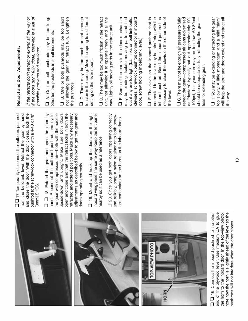
18
❏ ❏
16.
Con
nect
the
inb
oard
pus
hrod
to
the
othe
r en
d of
the
ply
woo
d le
ver.
Use
med
ium
CA
to
glue
th
e ho
rn t
o th
e in
boar
d do
or.
In t
he t
op-v
iew
pho
to,
note
how
the
horn
is s
light
ly a
head
of t
he le
ver s
o th
e pu
shro
ds w
ill n
ot in
terf
ere
whe
n th
e do
or c
lose
s.
❏ ❏
17.
Tem
pora
rily
disc
onne
ct th
e ou
tboa
rd p
ushr
od
from
the
bel
lcra
nk l
ever
. R
etra
ct t
he g
ear
by h
and
and
clos
e th
e do
or.
With
the
doo
r cl
osed
, lo
ck t
he
push
rod
to th
e sc
rew
-lock
con
nect
or w
ith a
4-4
0 x
1/8"
[3
mm
] SH
CS
.
❏ ❏
18.
Ext
end
the
gear
and
ope
n th
e do
or b
y ha
nd.
Rec
onne
ct t
he o
utbo
ard
push
rod
and
cycl
e th
e ge
ar w
ith c
ompr
esse
d ai
r—bo
th w
ith t
he n
acel
le
upsi
de-d
own
and
uprig
ht.
Mak
e su
re
both
do
ors
open
and
clo
se a
nd t
hat
the
retr
act
lock
s in
bot
h th
e re
trac
ted
and
exte
nd p
ositi
ons.
Mak
e an
y ne
cess
ary
adju
stm
ents
as
desc
ribed
bel
ow t
o ge
t th
e ge
ar a
nd
door
s op
erat
ing
corr
ectly
.
❏ 1
9. M
ount
and
hoo
k up
the
doo
rs o
n th
e rig
ht
inbo
ard
win
g pa
nel t
he s
ame
way
. Kee
p th
e le
ft pa
nel
near
by s
o it
can
be u
sed
as a
ref
eren
ce.
❏ 2
0. O
nce
you
get
both
doo
rs o
pera
ting
corr
ectly
an
d re
liabl
y, s
nap
a ny
lon
reta
iner
ont
o bo
th s
crew
-lo
ck c
onne
ctor
s on
the
horn
s on
the
inbo
ard
door
s.
Ret
ract
an
d D
oo
r A
dju
stm
ents
:
If th
e re
trac
ts d
on’t
retr
act o
r ex
tend
all
the
way
or
if th
e do
ors
don’
t fu
lly c
lose
, fo
llow
ing
is a
lis
t of
po
ssib
le p
robl
ems
and
solu
tions
:
❏ A
. O
ne o
r bo
th p
ushr
ods
may
be
too
long
. S
hort
en th
e pu
shro
ds in
sm
all i
ncre
men
ts.
❏ B
. O
ne o
r bo
th p
ushr
ods
may
be
too
shor
t no
t al
low
ing
the
gear
to
retr
act
fully
. Le
ngth
en
the
push
rods
.
❏ C
. T
here
may
be
too
muc
h or
not
eno
ugh
tens
ion
in th
e sp
ring.
Mov
e th
e sp
ring
to a
diff
eren
t se
tting
on
the
leve
r m
ount
.
❏ D
. The
re m
ay b
e to
o m
uch
fric
tion
in th
e re
trac
t un
it, n
ot a
llow
ing
it to
ope
rate
fre
ely
and
all
the
way
. Lig
htly
oil
mov
ing
part
s in
the
retr
act u
nit.
❏ E
. S
ome
of t
he p
arts
in
the
door
mec
hani
sm
may
be
bind
ing.
Iso
late
mov
ing
part
s an
d fi n
d ou
t if
any
are
too
tight
(ba
ll lin
ks o
n ba
ll lin
k ba
lls,
clev
ises
, scr
ew-lo
ck p
ushr
od c
onne
ctor
in in
boar
d do
or, s
crew
hol
ding
in b
ellc
rank
leve
r.)
❏ F
. T
he c
levi
s on
the
inb
oard
pus
hrod
tha
t is
co
nnec
ted
to th
e le
ver
may
be
inte
rfer
ing
with
the
inbo
ard
push
rod.
Ben
d th
e in
boar
d pu
shro
d as
ne
cess
ary
to c
lear
the
cle
vis
on t
he o
ther
sid
e of
th
e le
ver.
❏ G
. The
re m
ay n
ot b
e en
ough
air
pres
sure
to fu
lly
retr
act t
he g
ear—
com
pres
sed
air
cans
adv
ertis
ed
as “
dust
ers”
typ
ical
ly p
ut o
ut a
ppro
xim
atel
y 90
-10
0psi
, bu
t yo
ur c
an m
ay b
e to
o lo
w.
60-8
0psi
sh
ould
be
adeq
uate
for
fully
ret
ract
ing
the
gear
—le
ss fo
r ex
tend
ing
gear
.
❏ H
. You
may
be
exte
ndin
g or
ret
ract
ing
the
gear
to
o sl
owly
. A
litt
le m
omen
tum
and
a m
ild “
slam
” w
ill h
elp
the
stru
t and
doo
rs e
xten
d an
d re
trac
t all
the
way
.
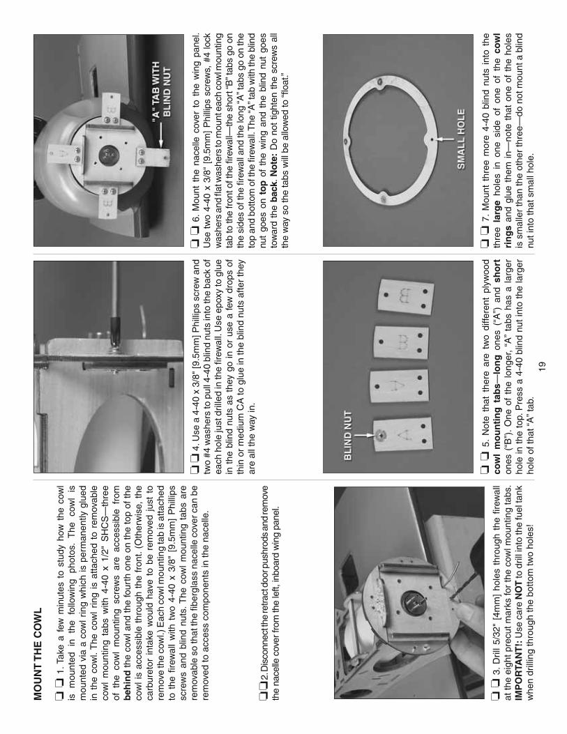
19
MO
UN
T T
HE
CO
WL
❏ ❏
1. T
ake
a fe
w m
inut
es t
o st
udy
how
the
cow
l is
m
ount
ed
in
the
follo
win
g ph
otos
. T
he
cow
l is
m
ount
ed v
ia a
cow
l rin
g w
hich
is p
erm
anen
tly g
lued
in
the
cow
l. T
he c
owl
ring
is a
ttach
ed t
o re
mov
able
co
wl
mou
ntin
g ta
bs w
ith 4
-40
x 1/
2" S
HC
S—
thre
e of
the
cow
l m
ount
ing
scre
ws
are
acce
ssib
le f
rom
b
ehin
d th
e co
wl a
nd th
e fo
urth
one
on
the
top
of th
e co
wl i
s ac
cess
ible
thr
ough
the
fro
nt. (
Oth
erw
ise,
the
ca
rbur
etor
int
ake
wou
ld h
ave
to b
e re
mov
ed j
ust
to
rem
ove
the
cow
l.) E
ach
cow
l mou
ntin
g ta
b is
atta
ched
to
the
fi r
ewal
l w
ith t
wo
4-40
x 3
/8"
[9.5
mm
] P
hilli
ps
scre
ws
and
blin
d nu
ts. T
he c
owl
mou
ntin
g ta
bs a
re
rem
ovab
le s
o th
at th
e fi b
ergl
ass
nace
lle c
over
can
be
rem
oved
to a
cces
s co
mpo
nent
s in
the
nace
lle.
❏ ❏
2. D
isco
nnec
t the
retra
ct d
oor p
ushr
ods
and
rem
ove
the
nace
lle c
over
from
the
left,
inbo
ard
win
g pa
nel.
❏ ❏
3.
Dril
l 5/
32"
[4m
m]
hole
s th
roug
h th
e fi r
ewal
l at
the
eigh
t pre
cut m
arks
for
the
cow
l mou
ntin
g ta
bs.
IMP
OR
TAN
T!:
Use
car
e N
OT
to d
rill i
nto
the
fuel
tank
w
hen
drill
ing
thro
ugh
the
botto
m tw
o ho
les!
❏ ❏
4. U
se a
4-4
0 x
3/8"
[9.5
mm
] Phi
llips
scr
ew a
nd
two
#4 w
ashe
rs to
pul
l 4-4
0 bl
ind
nuts
into
the
back
of
each
hol
e ju
st d
rille
d in
the
fi rew
all.
Use
epo
xy to
glu
e in
the
blin
d nu
ts a
s th
ey g
o in
or
use
a fe
w d
rops
of
thin
or
med
ium
CA
to g
lue
in th
e bl
ind
nuts
afte
r th
ey
are
all t
he w
ay in
.
❏ ❏
5.
Not
e th
at t
here
are
tw
o di
ffere
nt p
lyw
ood
cow
l m
ou
nti
ng
tab
s—lo
ng
one
s (“
A”)
and
sh
ort
on
es (
“B”)
. O
ne o
f th
e lo
nger
, “A
” ta
bs h
as a
lar
ger
hole
in t
he t
op. P
ress
a 4
-40
blin
d nu
t in
to t
he la
rger
ho
le o
f tha
t “A
” tab
.
❏ ❏
6.
Mou
nt t
he n
acel
le c
over
to
the
win
g pa
nel.
Use
tw
o 4-
40 x
3/8
" [9
.5m
m]
Phi
llips
scr
ews,
#4
lock
w
ashe
rs a
nd fl
at w
ashe
rs to
mou
nt e
ach
cow
l mou
ntin
g ta
b to
the
fron
t of t
he fi
rew
all—
the
shor
t “B
” tab
s go
on
the
side
s of
the
fi rew
all a
nd th
e lo
ng “A
” tab
s go
on
the
top
and
botto
m o
f the
fi re
wal
l. T
he “A
” tab
with
the
blin
d nu
t go
es o
n to
p o
f th
e w
ing
and
the
blin
d nu
t go
es
tow
ard
the
bac
k. N
ote
: D
o no
t tig
hten
the
scr
ews
all
the
way
so
the
tabs
will
be
allo
wed
to “fl
oat
.”
❏ ❏
7.
Mou
nt t
hree
mor
e 4-
40 b
lind
nuts
int
o th
e th
ree
larg
e ho
les
in o
ne s
ide
of o
ne o
f th
e co
wl
rin
gs
and
glue
the
m i
n—no
te t
hat
one
of t
he h
oles
is
sm
alle
r th
an th
e ot
her
thre
e—do
not
mou
nt a
blin
d nu
t int
o th
at s
mal
l hol
e.

20
❏ ❏
8.
Mou
nt t
he c
owl
ring
to t
he c
owl
mou
ntin
g ta
bs w
ith fo
ur 4
-40
x 1/
2" S
HC
S, #
4 lo
ck w
ashe
rs a
nd
#4 fl
at w
ashe
rs. N
ote
that
the
top
scre
w g
oes
in fr
om
the
fron
t, bu
t the
oth
er th
ree
go in
thro
ugh
the
back
. A
3/32
" ba
ll en
d he
x w
renc
h (G
PM
R80
02)
is v
irtu
ally
a
mu
st fr
om h
ere
on o
ut. O
nce
the
cow
l rin
g ha
s be
en
fast
ened
to a
ll th
e ta
bs, g
o ah
ead
and
tight
en u
p th
e sc
rew
s ho
ldin
g th
e ta
bs to
the
fi rew
all.
❏ ❏
9. M
ount
the
engi
ne m
ount
and
eng
ine
with
out
the
muf
fl er.
Trim
the
cow
l rin
g as
nec
essa
ry u
ntil
you
can
get t
he m
uffl e
r to
fi t.
❏ ❏
10.
Rem
ove
the
muf
fl er
from
the
eng
ine.
Get
re
ady
to s
tart
cut
ting
fi ber
glas
s an
d re
ad t
he H
ot T
ip
belo
w th
at li
sts
reco
mm
ende
d to
ols,
wor
king
tips
and
sa
fety
war
ning
s fo
r cu
tting
fi be
rgla
ss.
Too
ls F
or
Cu
ttin
g F
iber
gla
ss
The
re a
re s
ever
al fi
berg
lass
par
ts o
n th
is m
odel
. A
few
of t
hem
will
requ
ire c
uttin
g an
d tr
imm
ing
to e
nd u
p w
ith th
e be
st fi
t. Fo
llow
thes
e w
arni
ngs
and
use
the
sugg
este
d to
ols
for w
orki
ng s
afel
y w
ith fi
berg
lass
.
A. D
o n
ot b
e ca
sual
wh
en w
ork
ing
with
fi b
erg
lass
. A
lway
s w
ear
eye
and
resp
irato
ry p
rote
ctio
n.
B. W
ork
in a
wel
l-ven
tilat
ed a
rea—
wor
king
und
er a
n ex
haus
t fan
that
will
dra
w fi
berg
lass
dus
t aw
ay is
be
st. I
f pos
sibl
e, c
uttin
g fi b
ergl
ass
outd
oors
may
al
so b
e a
good
idea
.
C. W
ear
a lo
ng-s
leev
e sh
irt w
hen
cutti
ng fi
berg
lass
.
D. I
f usi
ng a
hig
h-sp
eed
rota
ry to
ol, h
earin
g pr
otec
tion
is r
ecom
men
ded.
E. F
ollo
win
g ar
e th
e be
st to
ols
for c
uttin
g fi b
ergl
ass:
I.
A r
otar
y to
ol.
II.
A fi
ne-p
oint
, fel
t-tip
pen
for m
arki
ng. (
Afte
rwar
d,
ink
can
be r
emov
ed w
ith a
pap
er t
owel
and
de
natu
red
alco
hol.)
III.
A 3
/32"
bal
l driv
er w
ill b
e in
disp
ensa
ble
whe
n fi t
ting
the
cow
l lat
er.
IV.
Cur
ved
and
fl at h
obby
fi le
s.
V.
Var
ious
cut
ting
bits
for
you
r ro
tary
too
l—th
e ca
rbid
e cu
tter
is b
est
for
mak
ing
initi
al c
uts.
A
bras
ive
drum
san
ders
wor
k w
ell
for
“fi n
e-tu
ning
.” V
I. A
sm
all s
andi
ng b
oard
mad
e fr
om a
pie
ce o
f pl
ywoo
d w
ith s
andp
aper
glu
ed o
n. V
II. S
mal
l sh
eets
of
med
ium
-grit
san
dpap
er t
o sm
ooth
rou
gh e
dges
.
❏ ❏
11.
Ret
rieve
you
r fi b
ergl
ass
cutti
ng t
ools
and
sa
fety
equ
ipm
ent.
Cut
one
of
the
fi ber
glas
s en
gine
co
wls
to
fi t o
ver
the
engi
ne—
it do
esn’
t m
atte
r w
hich
of
the
tw
o co
wls
you
cho
ose
beca
use
they
are
bot
h th
e sa
me.
Cut
ting
the
hole
is b
asic
ally
a tr
ial-a
nd-e
rror
pr
oces
s w
here
you
cut
-and
-fi t
and
cut-
and-
fi t th
e co
wl
until
it g
oes
over
the
eng
ine.
If
usin
g a
4-st
roke
, th
e co
wl fi
ttin
g pr
oced
ure
will
be
easi
er if
the
valv
e co
ver
is t
empo
raril
y re
mov
ed.
If us
ing
a 2-
stro
ke t
he c
owl
will
be
easi
er to
fi t i
f the
hea
d is
tem
pora
rily
rem
oved
. T
his
will
allo
w th
e co
wl t
o fi t
with
out h
avin
g to
fi na
lize
the
exac
t si
ze,
shap
e an
d lo
catio
n of
the
cut
out
until
af
ter
the
cow
l has
bee
n pe
rman
ently
mou
nted
. Sta
rt
by t
ryin
g to
fi t
the
cow
l ov
er t
he e
ngin
e as
far
as
it w
ill g
o. U
se a
fi n
e-po
int
felt-
tip p
en o
r a
lead
pen
cil
to m
ark
the
insi
de o
f th
e co
wl
in t
he a
ppro
xim
ate
loca
tion
whe
re th
e en
gine
will
stic
k ou
t.

21
❏ ❏
12.
Usi
ng th
e m
arks
insi
de th
e co
wl a
s a
guid
e,
use
your
rot
ary
tool
with
a c
arbi
de c
utte
r to
cut
a
rou
gh
, u
nd
ersi
ze s
tart
er h
ole
in
the
cow
l. S
ee i
f yo
u ca
n fi t
the
cow
l ove
r th
e en
gine
. Con
tinue
fi tt
ing
and
cutti
ng t
he c
owl u
ntil
you
can
get
it in
to p
ositi
on
over
the
head
and
the
cow
l rin
g—cu
t onl
y as
muc
h as
ne
eded
to g
et th
e co
wl o
ver
the
engi
ne—
fi nal
cut
ting
and
trim
min
g w
ill b
e do
ne l
ater
afte
r th
e co
wl
and
cow
l rin
g ha
ve b
een
perm
anen
tly jo
ined
.
❏ ❏
13.
If
you
have
n’t
yet
done
so,
ass
embl
e th
e bu
ildin
g st
and
that
cam
e w
ith t
his
kit
by u
sing
epo
xy
or w
hite
glu
e to
glu
e th
e pl
astic
tub
es i
nto
the
foam
cr
adle
s. A
pply
the
foam
cus
hion
str
ips
to th
e fr
ont a
nd
back
of b
oth
crad
les
whe
re th
ey s
uppo
rt th
e fu
sela
ge.
❏ ❏
14.
Onc
e yo
u ca
n ge
t the
cow
l ove
r th
e en
gine
, pl
ace
the
fuse
lage
in t
he b
uild
ing
stan
d. T
hen,
fi t
the
inbo
ard
win
g pa
nel t
o th
e fu
sela
ge w
ith th
e al
umin
um
join
er t
ubes
—no
nee
d to
use
the
scr
ews
to s
ecur
e th
e tu
bes
in t
he w
ing
pane
l at
thi
s tim
e. C
ount
er-
wei
ght
mad
e fr
om b
ags
of s
hot
or s
omet
hing
sim
ilar
will
be
need
ed o
n th
e tu
bes
com
ing
out
of t
he r
ight
si
de o
f the
fuse
lage
.
❏ ❏
15.
Use
med
ium
-grit
san
dpap
er to
rou
ghen
the
insi
de o
f th
e co
wl a
ll th
e w
ay a
roun
d w
here
the
cow
l rin
g w
ill g
o.
❏
❏
16.
Test
fi t
th
e le
ft,
fi ber
glas
s ca
rbu
reto
r in
take
to
the
top
of t
he w
ing.
Mak
e an
y ad
just
men
ts
nece
ssar
y fo
r a g
ood
fi t. T
hen,
dril
l 1/1
6" [1
.6m
m] h
oles
in
to t
he w
ing
thro
ugh
the
hole
s in
the
int
ake.
Mou
nt
the
carb
uret
or in
take
to
the
win
g w
ith e
ight
#2
x 3/
8"
[9.5
mm
] but
ton-
head
Alle
n sc
rew
s.
❏ ❏
17.
Trim
the
top
of
the
cow
l as
nec
essa
ry t
o ac
com
mod
ate
the
inta
ke. W
ith th
e in
take
and
cow
l in
posi
tion,
pla
ce a
pro
pelle
r on
the
engi
ne a
nd p
ositi
on
the
cow
l so
it
look
s be
st—
due
to t
he o
ut t
hrus
t an
d do
wn
thru
st o
f the
eng
ine,
a c
ompr
omis
e w
ill h
ave
to
be m
ade
betw
een
cent
erin
g th
e pr
opel
ler
in th
e co
wl
and
alig
ning
the
cow
l w
ith t
he n
acel
le c
over
—if
the
prop
elle
r w
as c
ente
red
in t
he f
ront
of
the
cow
l, th
e ou
twar
d an
d do
wnw
ard
angl
e of
the
cow
l w
ould
n’t
look
rig
ht. I
f th
e co
wl w
ere
alig
ned
perf
ectly
with
the
na
celle
the
prop
elle
r w
ould
be
too
far
off c
ente
r in
the
cow
l. Lo
ok a
t the
cow
l fro
m d
iffer
ent a
ngle
s an
d ge
t it
posi
tione
d w
here
it lo
oks
best
.
❏ ❏
18.
Onc
e sa
tisfi e
d w
ith th
e po
sitio
n of
the
cow
l, us
e m
ediu
m C
A a
nd a
ccel
erat
or to
tack
glu
e th
e co
wl
to th
e co
wl r
ing
in a
bout
four
or
six
diffe
rent
spo
ts.
❏ ❏
19.
With
out a
ccid
enta
lly b
reak
ing
the
cow
l rin
g fr
ee fr
om th
e co
wl,
use
your
3/3
2" b
all-e
nd h
ex w
renc
h to
loo
sen
the
scre
ws
and
care
fully
rem
ove
the
cow
l fr
om t
he n
acel
le.
Use
30-
min
ute
epox
y m
ixed
with
m
illed
fi b
ergl
ass
or m
icro
ballo
ons
to s
ecur
ely
glue
th
e co
wl r
ing
to th
e co
wl w
ith a
sm
all fi
llet
all
the
way
ar
ound
bot
h si
des.
❏ ❏
20.
Cut
a s
mal
l, ro
unde
d sl
ot in
the
top
of
the
cow
l to
acc
omm
odat
e th
e ba
ll-en
d he
x w
renc
h to
ac
cess
the
top
cow
l mou
ntin
g sc
rew
. Acc
ess
thro
ugh
this
slo
t will
be
nece
ssar
y af
ter t
he re
plic
a en
gine
has
be
en in
stal
led.
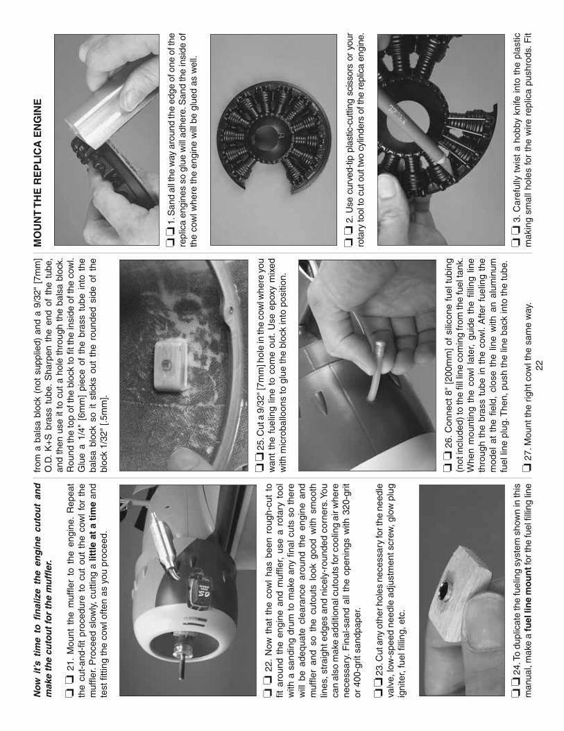
22
No
w i
t’s t
ime
to fi
nal
ize
the
eng
ine
cuto
ut
and
m
ake
the
cuto
ut
for
the
mu
ffl e
r.
❏ ❏
21.
Mou
nt t
he m
uffl e
r to
the
eng
ine.
Rep
eat
the
cut-
and-
fi t p
roce
dure
to
cut
out
the
cow
l fo
r th
e m
uffl e
r. P
roce
ed s
low
ly, c
uttin
g a
littl
e at
a t
ime
and
test
fi tti
ng th
e co
wl o
ften
as y
ou p
roce
ed.
❏ ❏
22.
Now
tha
t th
e co
wl
has
been
rou
gh-c
ut t
o fi t
aro
und
the
engi
ne a
nd m
uffl e
r, us
e a
rota
ry t
ool
with
a s
andi
ng d
rum
to
mak
e an
y fi n
al c
uts
so t
here
w
ill b
e ad
equa
te c
lear
ance
aro
und
the
engi
ne a
nd
muf
fl er
and
so t
he c
utou
ts l
ook
good
with
sm
ooth
lin
es, s
trai
ght e
dges
and
nic
ely-
roun
ded
corn
ers.
You
ca
n al
so m
ake
addi
tiona
l cut
outs
for c
oolin
g ai
r whe
re
nece
ssar
y. F
inal
-san
d al
l th
e op
enin
gs w
ith 3
20-g
rit
or 4
00-g
rit s
andp
aper
.
❏ ❏
23.
Cut
any
oth
er h
oles
nec
essa
ry fo
r the
nee
dle
valv
e, lo
w-s
peed
nee
dle
adju
stm
ent s
crew
, glo
w p
lug
igni
ter,
fuel
fi lli
ng, e
tc.
❏ ❏
24.
To
dupl
icat
e th
e fu
elin
g sy
stem
sho
wn
in th
is
man
ual,
mak
e a
fuel
lin
e m
ou
nt f
or th
e fu
el fi
lling
line
from
a b
alsa
blo
ck (
not
supp
lied)
and
a 9
/32"
[7m
m]
O.D
. K
+S
bra
ss t
ube.
Sha
rpen
the
end
of
the
tube
, an
d th
en u
se it
to
cut
a ho
le t
hrou
gh t
he b
alsa
blo
ck.
Rou
nd th
e to
p of
the
bloc
k to
fi t t
he in
side
of t
he c
owl.
Glu
e a
1/4"
[6m
m]
piec
e of
the
bra
ss t
ube
into
the
ba
lsa
bloc
k so
it
stic
ks o
ut t
he r
ound
ed s
ide
of t
he
bloc
k 1/
32"
[.5m
m].
❏ ❏
25.
Cut
a 9
/32"
[7m
m] h
ole
in th
e co
wl w
here
you
w
ant
the
fuel
ing
line
to c
ome
out.
Use
epo
xy m
ixed
w
ith m
icro
ballo
ons
to g
lue
the
bloc
k in
to p
ositi
on.
❏ ❏
26.
Con
nect
8"
[200
mm
] of
sili
cone
fue
l tub
ing
(not
incl
uded
) to
the
fi ll l
ine
com
ing
from
the
fuel
tank
. W
hen
mou
ntin
g th
e co
wl
late
r, gu
ide
the
fi llin
g lin
e th
roug
h th
e br
ass
tube
in
the
cow
l. A
fter
fuel
ing
the
mod
el a
t th
e fi e
ld,
clos
e th
e lin
e w
ith a
n al
umin
um
fuel
line
plu
g. T
hen,
pus
h th
e lin
e ba
ck in
to th
e tu
be.
❏ 2
7. M
ount
the
right
cow
l the
sam
e w
ay.
MO
UN
T T
HE
RE
PL
ICA
EN
GIN
E
❏ ❏
1. S
and
all t
he w
ay a
roun
d th
e ed
ge o
f one
of t
he
repl
ica
engi
nes
so g
lue
will
adh
ere.
San
d th
e in
side
of
the
cow
l whe
re th
e en
gine
will
be
glue
d as
wel
l.
❏ ❏
2. U
se c
urve
d-tip
pla
stic
-cut
ting
scis
sors
or
your
ro
tary
tool
to c
ut o
ut tw
o cy
linde
rs o
f the
repl
ica
engi
ne.
❏ ❏
3. C
aref
ully
tw
ist
a ho
bby
knife
into
the
pla
stic
m
akin
g sm
all h
oles
for
the
wire
rep
lica
push
rods
. Fit
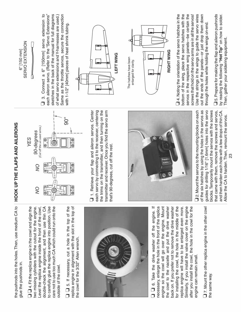
23
the
push
rods
into
the
hole
s. T
hen,
use
med
ium
CA
to
glue
the
push
rods
in.
❏ ❏
4. F
it th
e re
plic
a en
gine
in th
e co
wl a
nd a
lign
the
two
mis
sing
cyl
inde
rs w
ith t
he c
utou
t fo
r th
e en
gine
. Le
vel t
he r
eplic
a en
gine
insi
de t
he f
ront
of
the
cow
l, do
uble
-che
ck t
he a
lignm
ent,
and
then
use
thi
n C
A
to c
aref
ully
glu
e th
e re
plic
a en
gine
into
pos
ition
. Use
ca
re n
ot to
use
too
muc
h C
A w
hich
cou
ld ru
n on
to th
e ou
tsid
e of
the
cow
l.
❏ ❏
5.
If ne
cess
ary,
cut
a h
ole
in t
he t
op o
f th
e re
plic
a en
gine
in a
lignm
ent
with
the
slo
t in
the
top
of
the
cow
l for
the
3/32
" A
llen
wre
nch.
❏ ❏
6.
Take
the
driv
e w
ashe
r of
f th
e en
gine
. If
nece
ssar
y, e
nlar
ge th
e ho
le in
the
fron
t of t
he r
eplic
a en
gine
so
the
cow
l w
ill g
o ov
er t
he e
ngin
e. M
ount
th
e co
wl
to t
he n
acel
le a
nd p
ut t
he d
rive
was
her
back
on.
If y
ou p
refe
r no
t to
rem
ove
the
driv
e w
ashe
r fo
r in
stal
ling
the
cow
l, th
e ho
le i
n th
e m
iddl
e of
the
re
plic
a en
gine
will
hav
e to
be
enla
rged
eve
n m
ore.
S
imila
rly,
if yo
u in
stal
l the
val
ve c
over
on
the
engi
ne
afte
r yo
u in
stal
l the
cow
l, th
e ho
le in
the
cow
l for
the
en
gine
can
rem
ain
smal
l.
❏ 7
. Mou
nt th
e ot
her
repl
ica
engi
ne in
the
othe
r co
wl
the
sam
e w
ay.
HO
OK
UP
TH
E F
LA
PS
AN
D A
ILE
RO
NS
❏ 1
. R
etrie
ve y
our
fl ap
and
aile
ron
serv
os.
Cen
ter
each
ser
vo b
y co
nnec
ting
it to
the
rece
iver
, cen
terin
g th
e tr
ims
on t
he t
rans
mitt
er,
and
then
tur
ning
on
the
tran
smitt
er a
nd re
ceiv
er. O
nce
you
fi nd
the
serv
o ar
m
that
’s 9
0-de
gree
s, c
ut o
ff th
e re
st.
❏ 2
. Mou
nt th
e se
rvos
to th
e m
ount
ing
bloc
ks o
n ea
ch
of th
e si
x ha
tche
s by
usi
ng th
e ho
les
in th
e se
rvos
as
guid
es fo
r dr
illin
g 1/
16"
[1.6
mm
] ho
les
into
the
ser
vo
bloc
ks. T
empo
raril
y m
ount
the
serv
os w
ith th
e sc
rew
s th
at c
ame
with
them
, rem
ove
the
scre
ws
and
serv
os,
and
then
har
den
each
hol
e w
ith a
few
dro
ps o
f thi
n C
A.
Allo
w th
e C
A to
har
den.
The
n, r
emou
nt th
e se
rvos
.
6" [1
50 m
m]
SE
RV
O E
XT
EN
SIO
N
❏ 3
. C
onne
ct
a 6"
[1
50m
m]
serv
o ex
tens
ion
to
each
aile
ron
serv
o. (
Ref
er t
o th
e “S
ervo
Ext
ensi
ons”
sk
etch
es in
the
bac
k of
the
man
ual f
or f
ull d
iagr
ams
of w
hat s
ervo
ext
ensi
ons
and
Y-ha
rnes
ses
are
used
.)
Sam
e as
the
thr
ottle
ser
vos,
sec
ure
the
conn
ectio
n w
ith 1
-1/2
" [4
0mm
] pie
ces
of h
eat s
hrin
k tu
bing
.
The
hat
ches
hav
e be
en
enla
rged
for
clar
ity.
LE
FT
WIN
G
RIG
HT
WIN
G
❏ 4
. Not
ing
the
orie
ntat
ion
of th
e se
rvo
hatc
hes
in th
e bo
ttom
of
the
win
g, p
lace
the
ser
vo h
atch
es w
ith t
he
serv
os i
n th
e re
spec
tive
win
g pa
nels
—be
cer
tain
the
sc
rew
s th
at h
old
on th
e se
rvo
arm
s ar
e in
all
the
serv
os!
Use
the
str
ings
in t
he w
ings
to
guid
e th
e se
rvo
wire
s ou
t th
e en
ds o
f th
e pa
nels
—or
jus
t dr
op t
hem
dow
n th
roug
h th
e ho
les
whi
le h
oldi
ng th
e w
ings
on-
end.
❏ 5
. Pre
pare
for m
akin
g th
e fl a
p an
d ai
lero
n pu
shro
ds
by r
eadi
ng t
he fo
llow
ing
“Ho
t Tip
” on
how
to
sold
er.
The
n, g
athe
r yo
ur s
olde
ring
equi
pmen
t.

24
Ho
w t
o S
old
er
A. U
se
dena
ture
d al
coho
l or
ot
her
solv
ent
to
thor
ough
ly c
lean
the
push
rod.
If n
eces
sary
, cut
th
e pu
shro
d w
ire to
the
corr
ect l
engt
h. R
ough
en
the
end
of t
he p
ushr
od w
ith c
oars
e sa
ndpa
per
whe
re it
is to
be
sold
ered
.
B. A
pply
a fe
w d
rops
of s
olde
ring
fl ux
to th
e en
d of
th
e pu
shro
d. T
hen,
use
a s
olde
ring
iron
or a
torc
h to
hea
t it.
“Tin
” the
hea
ted
area
with
silv
er s
old
er
(GP
MR
8070
) by
app
lyin
g th
e so
lder
to
the
end.
T
he h
eat o
f the
pus
hrod
sho
uld
mel
t the
sol
der—
not t
he fl
ame
of th
e to
rch
or s
olde
ring
iron—
thus
al
low
ing
the
sold
er t
o fl o
w. T
he e
nd o
f th
e w
ire
shou
ld b
e co
ated
with
sol
der
all t
he w
ay a
roun
d.
C. P
lace
the
clev
is o
n th
e en
d of
the
push
rod.
Add
an
othe
r dr
op o
f fl u
x, a
nd t
hen
heat
and
add
so
lder
. T
he s
ame
as b
efor
e, t
he h
eat
of t
he
part
s be
ing
sold
ered
sho
uld
mel
t th
e so
lder
, th
us a
llow
ing
it to
fl o
w.
Allo
w t
he j
oint
to
cool
na
tura
lly
with
out
dist
urbi
ng.
Avo
id
exce
ss
blob
s, b
ut m
ake
cert
ain
the
join
t is
tho
roug
hly
sold
ered
. The
sol
der s
houl
d be
shi
ny, n
ot ro
ugh.
If
nece
ssar
y, r
ehea
t the
join
t and
allo
w to
coo
l.
D. I
mm
edia
tely
afte
r th
e so
lder
has
sol
idifi
ed,
but
whi
le it
is s
till h
ot, u
se a
clo
th to
qui
ckly
wip
e of
f th
e fl u
x be
fore
it h
arde
ns. I
mp
ort
ant:
Afte
r th
e jo
int
cool
s, c
oat
with
oil
to p
reve
nt r
ust.
No
te:
Do
not
use
the
acid
fl u
x th
at c
omes
with
silv
er
sold
er fo
r el
ectr
ical
sol
derin
g.
Thi
s is
w
hat
a pr
oper
ly
sold
ered
cle
vis
look
s lik
e—sh
iny
sold
er w
ith g
ood
fl ow
, no
blo
bs, fl
ux
rem
oved
.
❏ 6
. H
ook
up
the
fl aps
an
d ai
lero
ns
usin
g th
e ha
rdw
are
show
n. F
or t
he fl
aps
, no
te t
hat
whe
n th
e fl a
ps a
re f
ully
ret
ract
ed (
“up”
) th
e se
rvo
arm
s sh
ould
be
bac
k an
d w
hen
the
fl aps
are
ext
ende
d th
e se
rvo
arm
s sh
ould
be
forw
ard.
Als
o no
te th
at th
e fr
ont e
dge
of th
e fl a
p co
ntro
l hor
ns is
set
bac
k 3/
8" [1
0mm
] fro
m
the
TE
of
the
win
g an
d th
e fr
ont
edge
of
the
aile
ron
cont
rol
horn
s is
3/1
6" [
5mm
] fr
om t
he T
E o
f th
e w
ing.
Dril
l 1/
16"
[1.6
mm
] ho
les
for
the
cont
rol
horn
m
ount
ing
scre
ws.
Mou
nt t
he h
orns
with
#2
x 3/
8"
[9.5
mm
] P
hilli
ps s
crew
s an
d m
ount
the
hat
ches
with
#2
x 3
/8"
butto
n-he
ad A
llen
scre
ws.
Afte
r in
stal
ling
all t
he w
ood
scre
ws,
tem
pora
rily
rem
ove
the
scre
ws,
ad
d a
few
dro
ps o
f thi
n C
A to
eac
h ho
le, a
llow
the
CA
to
har
den
and
then
rei
nsta
ll al
l the
scr
ews.
AS
SE
MB
LE
TH
E T
AIL
HIN
GE
TH
E E
LE
VATO
RS
AN
D R
UD
DE
RS
❏ 1
. Use
30-
min
ute
epox
y to
hin
ge th
e ru
dder
s to
the
vert
ical
sta
biliz
ers.
Be
cert
ain
the
mou
ntin
g po
ints
in
the
rudd
ers
for
mou
ntin
g th
e co
ntro
l hor
ns a
re o
n th
e b
ott
om
and
als
o m
ake
sure
the
rudd
ers
aren
’t pu
shed
to
o cl
ose
up t
o th
e ve
rtic
al s
tabi
lizer
s. O
ther
wis
e,
cont
rol
thro
w m
ay b
e lim
ited.
Set
the
rud
ders
asi
de
whi
le w
orki
ng o
n th
e el
evat
ors.
❏ 2
. U
se c
oars
e sa
ndpa
per
to r
ough
en t
he t
orqu
e ar
m p
ortio
ns o
f th
e el
evat
or j
oine
r w
ire s
o gl
ue w
ill
adhe
re.
Slid
e tw
o pl
ywoo
d el
evat
or
join
er m
ou
nts
ov
er b
oth
ends
of t
he e
leva
tor
join
er w
ire. T
hen,
glu
e th
e tw
o se
ts o
f mou
nts
toge
ther
.
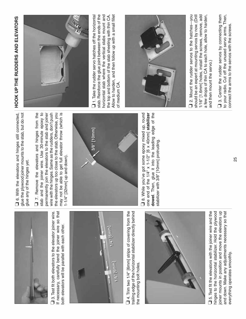
25
❏ 3
. Tes
t fi t
both
ele
vato
rs to
the
elev
ator
join
er w
ire.
If ne
cess
ary,
car
eful
ly b
end
the
join
er w
ire s
o th
at
both
ele
vato
rs w
ill b
e pa
ralle
l with
eac
h ot
her.
❏ 4
. Trim
tw
o 1/
4" [
6mm
] st
rips
of c
over
ing
from
the
tr
ailin
g ed
ge o
f the
hor
izon
tal s
tabi
lizer
dire
ctly
beh
ind
the
mou
ntin
g bo
lt ho
les.
❏ 5
. Tes
t fi t
the
elev
ator
s w
ith th
e jo
iner
wire
and
the
hing
es t
o th
e ho
rizon
tal
stab
ilize
r. H
old
the
plyw
ood
join
er m
ount
s in
pos
ition
and
mov
e th
e el
evat
ors
up
and
dow
n. M
ake
any
adju
stm
ents
nec
essa
ry s
o th
at
ever
ythi
ng o
pera
tes
smoo
thly
.
❏ 6
. With
the
ele
vato
rs a
nd h
inge
s st
ill c
onne
cted
, gl
ue th
e pl
ywoo
d jo
iner
mou
nts
to th
e st
ab, b
ut d
o no
t gl
ue a
ny o
f the
hin
ges
yet.
❏ 7
. R
emov
e th
e el
evat
ors
and
hing
es f
rom
the
st
ab a
nd t
he j
oine
r w
ire.
Use
30-
min
ute
epox
y to
pe
rman
ently
join
the
ele
vato
rs t
o th
e st
ab a
nd jo
iner
w
ire w
ith th
e hi
nges
. Sam
e as
the
rudd
ers,
don
’t pu
sh
the
elev
ator
s up
too
clos
e to
the
stab
. Oth
erw
ise,
you
m
ay n
ot b
e ab
le t
o ge
t fu
ll el
evat
or t
hrow
(w
hich
is
1-1/
4" [3
2mm
] up
and
dow
n).
❏ 8
. Whi
le y
ou’v
e go
t so
me
epox
y m
ixed
up,
rou
nd
one
end
of t
he 1
/4"
x 1-
1/2"
[6
x 40
mm
] st
abili
zer
do
wel
. T
hen,
glu
e it
into
the
lea
ding
edg
e of
the
st
abili
zer
with
3/8
" [1
0mm
] pro
trud
ing.
HO
OK
UP
TH
E R
UD
DE
RS
AN
D E
LE
VATO
RS
❏ 1
. Tak
e th
e ru
dder
ser
vo h
atch
es o
ff th
e ho
rizon
tal
stab
. Rei
nfor
ce th
e gl
ue jo
int b
etw
een
the
ends
of t
he
horiz
onta
l st
ab w
here
the
ver
tical
sta
bs m
ount
and
th
e to
p an
d bo
ttom
of t
he s
tab
shee
ting
with
thin
CA
. A
llow
to h
arde
n, a
nd th
en fo
llow
up
with
a s
mal
l fi ll
et
of m
ediu
m C
A.
❏ 2
. M
ount
the
rud
der
serv
os t
o th
e ha
tche
s—yo
u sh
ould
be
an e
xper
t at m
ount
ing
serv
os b
y no
w. (
Dril
l 1/
16"
[1.6
mm
] ho
les,
inst
all t
he s
crew
s, r
emov
e, a
dd
a fe
w d
rops
of t
hin
CA
to e
ach
hole
, allo
w to
har
den,
an
d th
en m
ount
the
serv
o.)
❏ 3
. C
ente
r th
e ru
dder
ser
vos
by c
onne
ctin
g th
em
to y
our
radi
o. C
ut o
ff th
e un
used
ser
vo a
rms.
The
n,
conn
ect t
he a
rms
to th
e se
rvos
with
the
scre
ws.
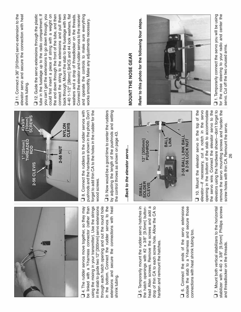
26
❏ 4
. The
rud
der
serv
os m
ove
toge
ther
, so
the
y m
ay
be l
inke
d w
ith a
Y-h
arne
ss c
onne
ctor
(ra
ther
tha
n us
ing
the
mix
ing
in y
our
tran
smitt
er).
Use
the
str
ings
in
the
stab
to g
uide
two
12" [
300m
m] s
ervo
ext
ensi
ons
thro
ugh
each
hat
ch o
peni
ng a
nd o
ut t
he r
ound
hol
e in
th
e bo
ttom
. C
onne
ct
the
rudd
er
serv
os
to
the
exte
nsio
ns
and
secu
re
the
conn
ectio
ns
with
he
at
shrin
k tu
bing
.
❏ 5
. Tem
pora
rily
mou
nt t
he r
udde
r se
rvo
hatc
hes
in
the
hatc
h op
enin
gs w
ith #
2 x
3/8"
[9.
5mm
] bu
tton-
head
Alle
n sc
rew
s. R
emov
e th
e sc
rew
s an
d ad
d a
drop
of
thin
CA
to
each
scr
ew h
ole.
Allo
w t
he C
A t
o ha
rden
and
rem
ount
the
hatc
hes.
❏ 6
. C
onne
ct
the
ends
of
th
e se
rvo
exte
nsio
ns
outs
ide
the
stab
to
a Y-
harn
ess
and
secu
re t
hose
co
nnec
tions
with
hea
t shr
ink
tubi
ng to
o.
❏ 7
. Mou
nt b
oth
vert
ical
sta
biliz
ers
to t
he h
oriz
onta
l st
abili
zer
with
4-4
0 x
3/8"
[9.
5mm
] P
hilli
ps s
crew
s an
d th
read
lock
er o
n th
e th
read
s.
❏ 8
. Con
nect
the
rud
ders
to
the
rudd
er s
ervo
s w
ith
push
rods
and
the
hard
war
e sh
own
in th
e ph
oto.
Don
’t fo
rget
to a
dd th
in C
A to
the
hole
s in
the
rudd
er fo
r th
e w
ood
scre
ws.
❏ 9
. Now
wou
ld b
e a
good
tim
e to
cen
ter t
he r
udde
rs
by a
djus
ting
the
leng
th o
f th
e pu
shro
ds a
nd s
ettin
g th
e co
ntro
l thr
ows
as s
how
n on
pag
e 43
.
…B
ack
to t
he
elev
ato
r se
rvo
…
❏ 1
0. M
ount
the
ele
vato
r se
rvo
in t
he t
op o
f th
e el
evat
or—
if ne
cess
ary,
cu
t a
notc
h in
th
e se
rvo
open
ing
in t
he b
otto
m o
f th
e st
ab t
o ac
com
mod
ate
the
serv
o w
ire.
Con
nect
the
ele
vato
r se
rvo
to t
he
elev
ator
s us
ing
the
hard
war
e sh
own—
don’
t fo
rget
to
rem
ove
the
serv
o m
ount
ing
scre
ws
and
hard
en t
he
scre
w h
oles
with
thin
CA
. Rem
ount
the
serv
o.
❏ 1
1. C
onne
ct a
36"
[910
mm
] ser
vo e
xten
sion
to th
e el
evat
or s
ervo
and
sec
ure
the
conn
ectio
n w
ith h
eat
shrin
k tu
bing
.
❏ 1
2. G
uide
the
serv
o ex
tens
ions
thro
ugh
the
plas
tic
tube
in
the
fuse
lage
up
to t
he r
adio
com
part
men
t. If
you
can’
t get
the
exte
nsio
ns to
go
dow
n th
roug
h, y
ou
coul
d fi r
st i
nser
t a
piec
e of
str
ing
with
a w
eigh
t on
th
e en
d do
wn
thro
ugh
the
fron
t of
the
tub
e, a
nd t
hen
conn
ect
the
strin
g to
the
ext
ensi
ons
and
pull
them
ba
ck th
roug
h. M
ount
the
stab
to th
e fu
sela
ge w
ith tw
o 4-
40 1
-1/2
" [3
8mm
] S
HC
S a
nd #
4 lo
ck w
ashe
rs,
fl at
was
hers
and
a d
rop
of t
hrea
dloc
ker
on t
he t
hrea
ds.
Con
nect
the
elev
ator
and
rudd
er s
ervo
s to
the
rece
iver
an
d op
erat
e th
e co
ntro
ls t
o m
ake
sure
eve
ryth
ing
wor
ks s
moo
thly
. Mak
e an
y ad
just
men
ts n
eces
sary
.
MO
UN
T T
HE
NO
SE
GE
AR
Ref
er t
o t
his
ph
oto
for
the
follo
win
g fo
ur
step
s.
❏ 1
. Tem
pora
rily
conn
ect t
he s
ervo
you
will
be
usin
g fo
r th
e no
se s
teer
ing
to y
our
radi
o an
d ce
nter
the
se
rvo.
Cut
off
the
two
unus
ed a
rms.

27
❏ 2
. Con
nect
one
of
the
24"
[610
mm
] br
aide
d st
eel
cabl
es t
o a
bras
s co
uple
r w
ith a
cop
per
swag
e—if
you
can’
t ge
t th
e en
d of
the
cab
le t
o go
thr
ough
the
sw
age,
use
a h
obby
kni
fe to
scr
ape
som
e of
the
plas
tic
coat
ing
from
the
end
of th
e ca
ble.
Tig
htly
squ
eeze
the
swag
e w
ith p
liers
so
the
cabl
e w
on’t
com
e ou
t.
❏ 3
. Pre
pare
ano
ther
cab
le t
he s
ame
way
. Con
nect
bo
th c
able
s to
the
nos
e st
eerin
g se
rvo
with
2-5
6 m
etal
cle
vise
s an
d si
licon
e cl
evis
ret
aine
rs.
❏ 4
. M
ount
the
nos
e st
eerin
g se
rvo
in t
he n
ose
stee
ring
serv
o tr
ay d
own
insi
de t
he f
usel
age—
it’s
alm
ost o
ut o
f rea
ch, b
ut n
ot to
o di
ffi cu
lt to
get
to.
❏ 5
. Gui
de th
e st
eerin
g ca
bles
up
thro
ugh
the
plas
tic
tube
s in
the
fron
t of t
he fu
sela
ge
Fro
m th
is p
oin
t fo
rwar
d s
tep
s th
at a
re fo
r ret
ract
s o
nly
are
pre
ced
ed b
y an
“R
” an
d s
tep
s th
at a
re
for
fi xe
d g
ear
on
ly a
re p
rece
ded
by
an “
F.”
If in
stal
ling
ret
ract
s sk
ip t
he
follo
win
g t
wo
ste
ps.
❏ F
6. A
ssem
ble
the
nose
gea
r m
ount
by
usin
g ei
ght
3 x
12m
m fl
at
head
Phi
llips
scr
ews
to a
ttach
th
e al
umin
um m
ount
ing
brac
kets
the
pla
stic
nos
e ge
ar b
lock
. Not
e w
hich
sid
e of
the
nose
gea
r bl
ock
is
the
botto
m.
❏ F
7. A
ttach
the
nos
e ge
ar w
ire t
o th
e no
se g
ear
mou
nt u
sing
the
hard
war
e sh
own
and
use
thre
adlo
cker
on
all
the
scre
ws.
If in
stal
ling
fi xe
d la
nd
ing
gea
r,sk
ip t
he
nex
t si
x st
eps.
Ref
er t
o t
his
ph
oto
for
the
follo
win
g t
hre
e st
eps.
❏ R
8. R
emov
e th
e st
rut
asse
mbl
y fr
om t
he r
etra
ct
unit
of t
he r
etra
ctab
le n
ose
land
ing
gear
. Grin
d a
fl at
spot
in
the
stee
ring
shaf
t fo
r th
e se
t sc
rew
in
th
e st
eeri
ng
arm
on
ly.
Thi
s is
bes
t do
ne w
ith a
cut
off
whe
el in
a r
otar
y to
ol to
get
the
fl at s
pot s
tart
ed, a
nd
then
usi
ng a
sm
all m
etal
fi le
to s
quar
e it
up.
❏ R
9. R
eass
embl
e th
e st
rut
asse
mbl
y, b
ut d
o no
t fi t
it
into
the
retr
act u
nit.
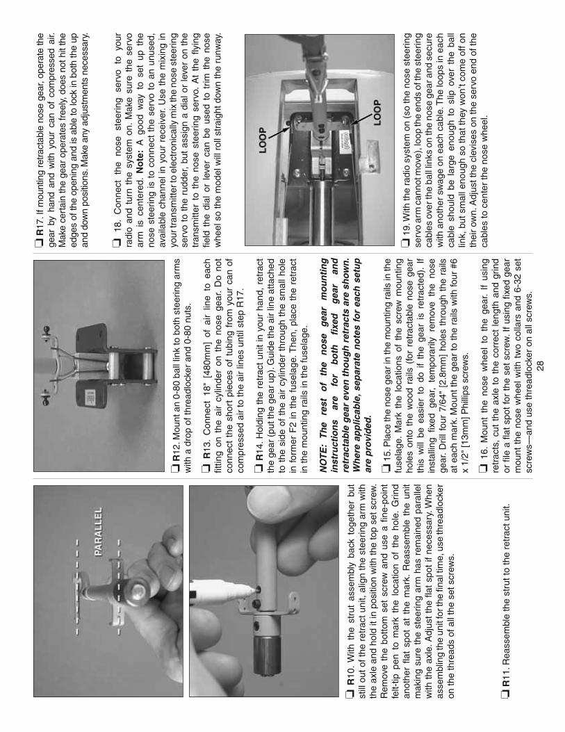
28
❏ R
10.
With
the
str
ut a
ssem
bly
back
tog
ethe
r bu
t st
ill o
ut o
f the
ret
ract
uni
t, al
ign
the
stee
ring
arm
with
th
e ax
le a
nd h
old
it in
pos
ition
with
the
top
set s
crew
. R
emov
e th
e bo
ttom
set
scr
ew a
nd u
se a
fi n
e-po
int
felt-
tip p
en t
o m
ark
the
loca
tion
of t
he h
ole.
Grin
d an
othe
r fl a
t sp
ot a
t th
e m
ark.
Rea
ssem
ble
the
unit
mak
ing
sure
the
ste
erin
g ar
m h
as r
emai
ned
para
llel
with
the
axl
e. A
djus
t th
e fl a
t sp
ot if
nec
essa
ry. W
hen
asse
mbl
ing
the
unit
for t
he fi
nal t
ime,
use
thre
adlo
cker
on
the
thre
ads
of a
ll th
e se
t scr
ews.
❏ R
11. R
eass
embl
e th
e st
rut t
o th
e re
trac
t uni
t.
❏ R
12. M
ount
an
0-80
bal
l lin
k to
bot
h st
eerin
g ar
ms
with
a d
rop
of th
read
lock
er a
nd 0
-80
nuts
.
❏ R
13.
Con
nect
18"
[48
0mm
] of
air
line
to e
ach
fi ttin
g on
the
air
cylin
der
on t
he n
ose
gear
. D
o no
t co
nnec
t th
e sh
ort
piec
es o
f tu
bing
fro
m y
our
can
of
com
pres
sed
air
to th
e ai
r lin
es u
ntil
step
R17
.
❏ R
14. H
oldi
ng t
he r
etra
ct u
nit
in y
our
hand
, re
trac
t th
e ge
ar (
put t
he g
ear
up).
Gui
de th
e ai
r lin
e at
tach
ed
to t
he s
ide
of t
he a
ir cy
linde
r th
roug
h th
e sm
all h
ole
in f
orm
er F
2 in
the
fus
elag
e. T
hen,
pla
ce t
he r
etra
ct
in th
e m
ount
ing
rails
in th
e fu
sela
ge.
NO
TE
: T
he
rest
o
f th
e n
ose
g
ear
mo
un
tin
g
inst
ruct
ion
s ar
e fo
r b
oth
fi
xed
g
ear
and
re
trac
tab
le g
ear
even
th
ou
gh
ret
ract
s ar
e sh
own
. W
her
e ap
plic
able
, sep
arat
e n
ote
s fo
r ea
ch s
etu
p
are
pro
vid
ed.
❏ 1
5. P
lace
the
nose
gea
r in
the
mou
ntin
g ra
ils in
the
fuse
lage
. M
ark
the
loca
tions
of
the
scre
w m
ount
ing
hole
s on
to t
he w
ood
rails
(fo
r re
trac
tabl
e no
se g
ear
this
will
be
easi
er t
o do
if
the
gear
is
retr
acte
d).
If in
stal
ling
fi xed
gea
r, te
mpo
raril
y re
mov
e th
e no
se
gear
. Dril
l fo
ur 7
/64"
[2.
8mm
] ho
les
thro
ugh
the
rails
at
eac
h m
ark.
Mou
nt th
e ge
ar to
the
rails
with
four
#6
x 1/
2" [1
3mm
] Phi
llips
scr
ews.
❏ 1
6. M
ount
the
nos
e w
heel
to
the
gear
. If
usin
g re
trac
ts,
cut
the
axle
to
the
corr
ect
leng
th a
nd g
rind
or fi
le a
fl at
spo
t fo
r th
e se
t sc
rew
. If
usin
g fi x
ed g
ear
mou
nt t
he n
ose
whe
el w
ith t
wo
colla
rs a
nd 6
-32
set
scre
ws—
and
use
thre
adlo
cker
on
all s
crew
s.
❏ R
17. I
f mou
ntin
g re
tract
able
nos
e ge
ar, o
pera
te th
e ge
ar b
y ha
nd a
nd w
ith y
our
can
of c
ompr
esse
d ai
r. M
ake
cert
ain
the
gear
ope
rate
s fr
eely
, doe
s no
t hit
the
edge
s of
the
open
ing
and
is a
ble
to lo
ck in
bot
h th
e up
an
d do
wn
posi
tions
. Mak
e an
y ad
just
men
ts n
eces
sary
.
❏ 1
8.
Con
nect
th
e no
se
stee
ring
serv
o to
yo
ur
radi
o an
d tu
rn t
he s
yste
m o
n. M
ake
sure
the
ser
vo
arm
is
cent
ered
. N
ote
: A
goo
d w
ay t
o se
t up
the
no
se s
teer
ing
is t
o co
nnec
t th
e se
rvo
to a
n un
used
, av
aila
ble
chan
nel i
n yo
ur r
ecei
ver.
Use
the
mix
ing
in
your
tran
smitt
er to
ele
ctro
nica
lly m
ix th
e no
se s
teer
ing
serv
o to
the
rud
der,
but
assi
gn a
dia
l or
leve
r on
the
tr
ansm
itter
to
the
nose
ste
erin
g se
rvo.
At
the
fl yin
g fi e
ld t
he d
ial
or l
ever
can
be
used
to
trim
the
nos
e w
heel
so
the
mod
el w
ill r
oll s
trai
ght d
own
the
runw
ay.
❏ 1
9. W
ith th
e ra
dio
syst
em o
n (s
o th
e no
se s
teer
ing
serv
o ar
m c
anno
t mov
e), l
oop
the
ends
of t
he s
teer
ing
cabl
es o
ver t
he b
all l
inks
on
the
nose
gea
r and
sec
ure
with
ano
ther
sw
age
on e
ach
cabl
e. T
he lo
ops
in e
ach
cabl
e sh
ould
be
larg
e en
ough
to
slip
ove
r th
e ba
ll lin
k, b
ut s
mal
l eno
ugh
so th
at th
ey w
on’t
com
e of
f on
thei
r ow
n. A
djus
t the
cle
vise
s on
the
serv
o en
d of
the
cabl
es to
cen
ter
the
nose
whe
el.
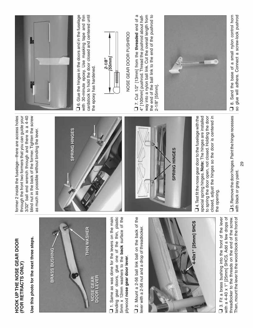
29
HO
OK
UP
TH
E N
OS
E G
EA
R D
OO
R(F
OR
RE
TR
AC
TS
ON
LY)
Use
th
is p
ho
to fo
r th
e n
ext
thre
e st
eps.
❏ 1
. Sam
e as
was
don
e fo
r th
e le
vers
on
the
mai
n la
ndin
g ge
ar
door
s,
glue
on
e of
th
e th
in,
plas
tic
5mm
x 1
2mm
was
hers
to
the
bac
k su
rfac
e of
the
pl
ywoo
d n
ose
gea
r d
oo
r le
ver.
❏ 2
. M
ount
a 2
-56
ball
link
ball
on t
he b
ack
of t
he
leve
r w
ith a
2-5
6 nu
t and
a d
rop
of th
read
lock
er.
❏ 3
. F
it a
bras
s bu
shin
g in
to t
he f
ront
of
the
leve
r w
ith a
4-4
0 x
1" [
25m
m]
SH
CS
. A
dd a
few
dro
ps o
f th
read
lock
er t
o th
e th
read
s on
the
end
of
the
scre
w.
The
n, m
ount
the
leve
r to
the
woo
d bl
ock
on th
e fr
ont o
f
form
er 2
insi
de th
e fu
sela
ge—
ther
e ar
e ac
cess
hol
es
thro
ugh
the
fron
t tw
o fo
rmer
s th
at y
ou c
an g
uide
you
r 3/
32"
ball
end
wre
nch
thro
ugh
and
ther
e is
a 4
-40
blin
d nu
t in
the
back
of t
he fo
rmer
. Tig
hten
the
scre
w
as m
uch
as p
ossi
ble
with
out b
indi
ng th
e le
ver.
❏ 4
. Tes
t fi t
the
nose
gea
r doo
r to
the
fuse
lage
with
the
spec
ial s
prin
g hi
nges
. No
te: T
he h
inge
s ar
e in
stal
led
to s
prin
g th
e do
or o
pen,
not
clo
sed.
Hol
ding
the
door
cl
osed
, ad
just
the
hin
ges
so t
he d
oor
is c
ente
red
in
the
open
ing.
❏ 5
. Rem
ove
the
door
hin
ges.
Pai
nt th
e hi
nge
rece
sses
w
ith b
lack
or
gray
pai
nt.
❏ 6
. Glu
e th
e hi
nges
in th
e do
ors
and
in th
e fu
sela
ge
with
30-
min
ute
epox
y. U
se m
aski
ng t
ape
and
thin
ca
rdst
ock
to h
old
the
door
clo
sed
and
cent
ered
unt
il th
e ep
oxy
has
hard
ened
.
2-1/
8"[5
5mm
]
NO
SE
GE
AR
DO
OR
PU
SH
RO
D
❏ 7
. C
ut 1
/2"
[13m
m]
from
the
th
read
ed e
nd o
f a
4" [1
00m
m] p
ushr
od. T
hrea
d th
e pu
shro
d ab
out h
alf-
way
into
a n
ylon
bal
l lin
k. C
ut t
he o
vera
ll le
ngth
fro
m
the
end
of t
he b
all
link
to t
he e
nd o
f th
e pu
shro
d to
2-
1/8"
[55m
m].
❏ 8
. S
and
the
base
of
a sm
all
nylo
n co
ntro
l ho
rn
so g
lue
will
adh
ere.
Con
nect
a s
crew
-lock
pus
hrod
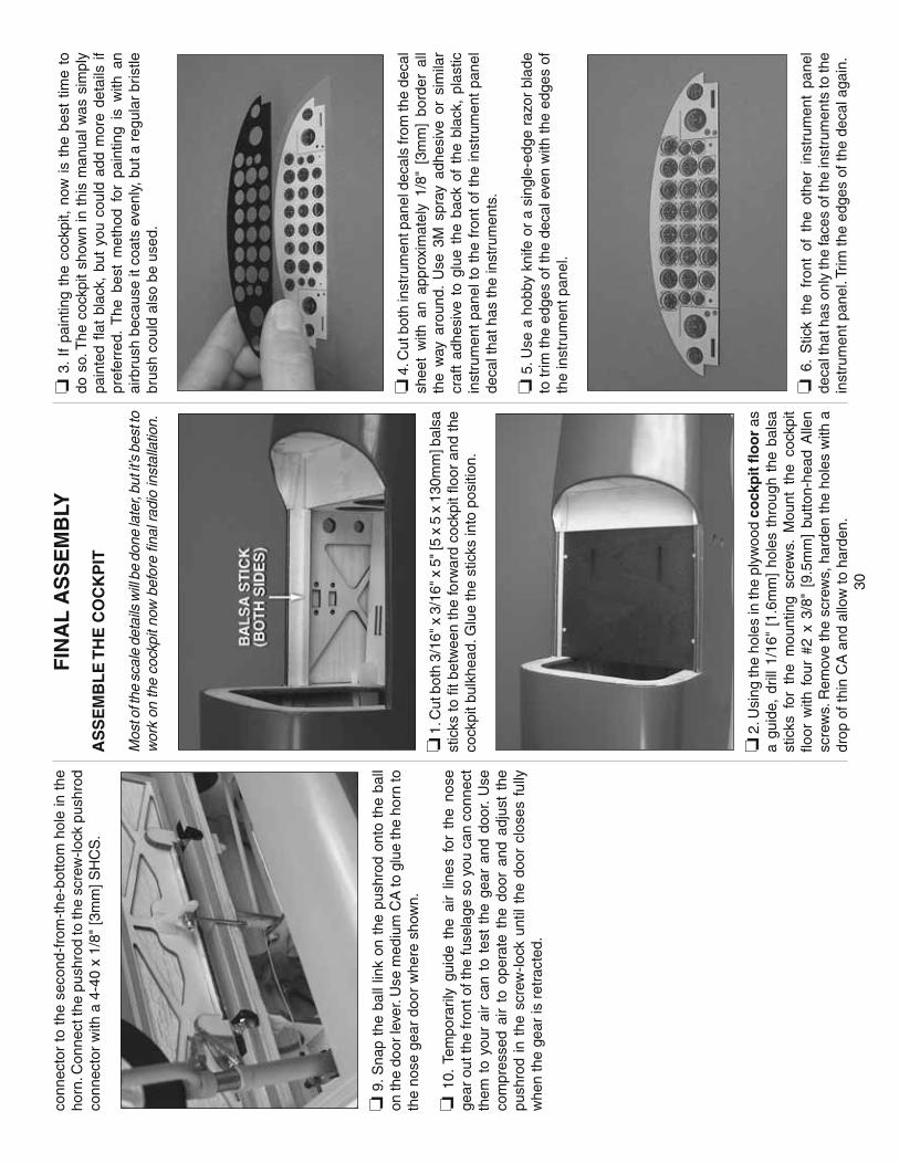
30
conn
ecto
r to
the
sec
ond-
from
-the
-bot
tom
hol
e in
the
ho
rn. C
onne
ct th
e pu
shro
d to
the
scre
w-lo
ck p
ushr
od
conn
ecto
r w
ith a
4-4
0 x
1/8"
[3m
m] S
HC
S.
❏ 9
. Sna
p th
e ba
ll lin
k on
the
pus
hrod
ont
o th
e ba
ll on
the
door
leve
r. U
se m
ediu
m C
A to
glu
e th
e ho
rn to
th
e no
se g
ear
door
whe
re s
how
n.
❏ 1
0. T
empo
raril
y gu
ide
the
air
lines
for
the
nos
e ge
ar o
ut th
e fr
ont o
f the
fuse
lage
so
you
can
conn
ect
them
to
your
air
can
to t
est
the
gear
and
doo
r. U
se
com
pres
sed
air
to o
pera
te t
he d
oor
and
adju
st t
he
push
rod
in t
he s
crew
-lock
unt
il th
e do
or c
lose
s fu
lly
whe
n th
e ge
ar is
ret
ract
ed.
FIN
AL
AS
SE
MB
LY
AS
SE
MB
LE
TH
E C
OC
KP
IT
Mos
t of t
he s
cale
det
ails
will
be
done
late
r, bu
t it’s
bes
t to
wor
k on
the
cock
pit n
ow b
efor
e fi n
al ra
dio
inst
alla
tion.
❏ 1
. Cut
bot
h 3/
16" x
3/1
6" x
5" [
5 x
5 x
130m
m] b
alsa
st
icks
to fi
t bet
wee
n th
e fo
rwar
d co
ckpi
t fl o
or a
nd th
e co
ckpi
t bul
khea
d. G
lue
the
stic
ks in
to p
ositi
on.
❏ 2
. Usi
ng th
e ho
les
in th
e pl
ywoo
d co
ckp
it fl
oo
r as
a
guid
e, d
rill
1/16
" [1
.6m
m]
hole
s th
roug
h th
e ba
lsa
stic
ks f
or t
he m
ount
ing
scre
ws.
Mou
nt t
he c
ockp
it fl o
or w
ith f
our
#2 x
3/8
" [9
.5m
m]
butto
n-he
ad A
llen
scre
ws.
Rem
ove
the
scre
ws,
har
den
the
hole
s w
ith a
dr
op o
f thi
n C
A a
nd a
llow
to h
arde
n.
❏ 3
. If
pain
ting
the
cock
pit,
now
is
the
best
tim
e to
do
so.
The
coc
kpit
show
n in
thi
s m
anua
l was
sim
ply
pain
ted
fl at
blac
k, b
ut y
ou c
ould
add
mor
e de
tails
if
pref
erre
d. T
he b
est
met
hod
for
pain
ting
is w
ith a
n ai
rbru
sh b
ecau
se it
coa
ts e
venl
y, b
ut a
reg
ular
bris
tle
brus
h co
uld
also
be
used
.
❏ 4
. Cut
bot
h in
stru
men
t pan
el d
ecal
s fr
om th
e de
cal
shee
t w
ith a
n ap
prox
imat
ely
1/8"
[3m
m]
bord
er a
ll th
e w
ay a
roun
d. U
se 3
M s
pray
adh
esiv
e or
sim
ilar
craf
t ad
hesi
ve t
o gl
ue t
he b
ack
of t
he b
lack
, pl
astic
in
stru
men
t pa
nel t
o th
e fr
ont
of t
he in
stru
men
t pa
nel
deca
l tha
t has
the
inst
rum
ents
.
❏ 5
. Use
a h
obby
kni
fe o
r a
sing
le-e
dge
razo
r bl
ade
to tr
im th
e ed
ges
of th
e de
cal e
ven
with
the
edge
s of
th
e in
stru
men
t pan
el.
❏ 6
. S
tick
the
fron
t of
the
oth
er i
nstr
umen
t pa
nel
deca
l tha
t has
onl
y th
e fa
ces
of th
e in
stru
men
ts to
the
inst
rum
ent p
anel
. Trim
the
edge
s of
the
deca
l aga
in.

31
❏ 7
. Use
a f
ew d
abs
of R
TV
sili
cone
rub
ber
to g
lue
the
com
plet
ed in
stru
men
t pan
el in
to th
e co
ckpi
t.
Ref
er t
o t
his
ph
oto
for
the
nex
t fo
ur
step
s.
❏ 8
. P
aint
the
edg
es o
f th
e th
ree
pilo
t fi g
ures
with
pl
astic
-com
patib
le fl
at
blac
k pa
int.
Whi
le t
he p
aint
is
dryi
ng,
care
fully
cut
the
pilo
t fi g
ures
fro
m t
he d
ecal
sh
eet.
Afte
r th
e pa
int
has
drie
d, a
ttach
the
dec
als
to
both
sid
es o
f eac
h fi g
ure.
❏ 9
. Set
the
tail-
gunn
er fi
gure
asi
de u
ntil
fi nis
hing
the
tail-
gunn
er c
ockp
it la
ter.
Glu
e th
e pi
lot
and
co-p
ilot
fi gur
es to
the
cock
pit fl
oor
.
❏ 1
0. T
rim th
e ba
ses
of th
e co
ckpi
t sea
ts a
s ne
cess
ary.
G
lue
the
seat
s to
the
cock
pit fl
oor
.
❏ 1
1. T
rim t
he b
ack
of b
oth
cont
rol
yoke
s to
fi t
the
yoke
pos
ts. G
lue
the
cont
rol y
okes
to th
e po
sts.
Pai
nt
any
addi
tiona
l sc
ale
deta
ils
pref
erre
d in
side
th
e co
ckpi
t. T
hen,
cut
the
yoke
pos
ts to
the
corr
ect h
eigh
t an
d gl
ue th
em in
to p
ositi
on.
❏ 1
2. P
ositi
on t
he c
ockp
it ca
nopy
ove
r th
e co
ckpi
t. D
rill
two
1/16
" [1
/6m
m]
hole
s th
roug
h ea
ch s
ide
of
the
cano
py in
to t
he f
usel
age
whe
re s
how
n. R
emov
e th
e ca
nopy
, en
larg
e th
e ho
les
in t
he c
anop
y on
ly
with
a 3
/32"
[2.4
mm
] dril
l, an
d th
en m
ount
the
cano
py
to
the
fuse
lage
w
ith
four
#2
x
3/8"
bu
tton-
head
A
llen
scre
ws.
HO
OK
UP
TH
E A
IR S
YS
TE
M
❏ 1
. M
ount
the
air
cont
rol
valv
e to
the
ply
woo
d ai
r co
ntr
ol
valv
e m
ou
nt
as s
how
n an
d gl
ue o
n th
e pl
ywoo
d tr
iang
ular
su
ppor
ts.
Con
nect
ab
out
4"
[100
mm
] eac
h of
“up,
” “do
wn”
and
“fi ll
” lin
e to
the
valv
e an
d m
ount
a 0
-80
ball
link
ball
to th
e va
lve
with
a 0
-80
nut a
nd a
dro
p of
thre
adlo
cker
.
❏ 2
. Mou
nt th
e ai
r fi ll
er v
alve
to th
e pl
ywoo
d fi
ll va
lve
mo
un
t p
iece
s. T
he v
alve
sho
uld
prot
rude
fro
m t
he
fron
t of
the
mou
nt 7
/32"
[5.
5mm
] so
it
will
be
fl ush
w
ith t
he o
utsi
de o
f th
e fu
sela
ge. C
onne
ct a
bout
one
in
ch [
25m
m]
of a
ir lin
e to
the
fi ll
val
ve a
nd c
onne
ct
one
of t
he “
T”
fi ttin
gs t
hat
cam
e w
ith t
he a
ir sy
stem
to
the
line.
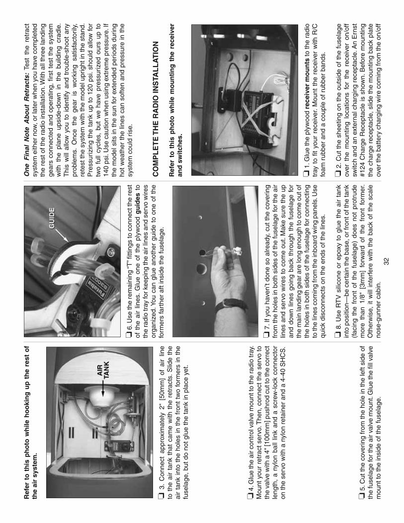
32
Ref
er t
o t
his
ph
oto
wh
ile h
oo
kin
g u
p t
he
rest
of
the
air
syst
em.
❏ 3
. C
onne
ct a
ppro
xim
atel
y 2"
[50
mm
] of
air
line
to t
he a
ir ta
nk t
hat
cam
e w
ith t
he r
etra
cts.
Slid
e th
e ai
r ta
nk in
to t
he h
oles
in t
he f
ront
tw
o fo
rmer
s in
the
fu
sela
ge, b
ut d
o no
t glu
e th
e ta
nk in
pla
ce y
et.
❏ 4
. Glu
e th
e ai
r con
trol
val
ve m
ount
to th
e ra
dio
tray
. M
ount
you
r re
trac
t ser
vo. T
hen,
con
nect
the
serv
o to
th
e va
lve
with
a 4
" [10
0mm
] pus
hrod
cut
to th
e co
rrec
t le
ngth
, a
nylo
n ba
ll lin
k an
d a
scre
w-lo
ck c
onne
ctor
on
the
serv
o w
ith a
nyl
on r
etai
ner
and
a 4-
40 S
HC
S.
❏ 5
. Cut
the
cove
ring
from
the
hole
in th
e le
ft si
de o
f th
e fu
sela
ge fo
r the
air
valv
e m
ount
. Glu
e th
e fi l
l val
ve
mou
nt to
the
insi
de o
f the
fuse
lage
.
❏ 6
. Use
the
rem
aini
ng “T
” fi tt
ings
to c
onne
ct th
e re
st
of t
he a
ir lin
es.
Glu
e on
e of
the
ply
woo
d g
uid
es t
o th
e ra
dio
tray
for k
eepi
ng th
e ai
r lin
es a
nd s
ervo
wire
s or
gani
zed.
You
can
glu
e an
othe
r gu
ide
to o
ne o
f th
e fo
rmer
s fa
rthe
r af
t ins
ide
the
fuse
lage
.
❏ 7
. If y
ou h
aven
’t do
ne s
o al
read
y, c
ut th
e co
verin
g fr
om th
e ho
les
in b
oth
side
s of
the
fuse
lage
for
the
air
lines
and
ser
vo w
ires
to c
ome
out.
Mak
e su
re th
e up
an
d do
wn
lines
goi
ng b
ack
thro
ugh
the
fuse
lage
for
th
e m
ain
land
ing
gear
are
long
eno
ugh
to c
ome
out o
f th
e ho
les
in b
oth
side
s of
the
fuse
lage
for
conn
ectin
g to
the
lines
com
ing
from
the
inbo
ard
win
g pa
nels
. Use
qu
ick
disc
onne
cts
on th
e en
ds o
f the
line
s.
❏ 8
. Use
RT
V s
ilico
ne o
r ep
oxy
to g
lue
the
air
tank
in
to p
ositi
on—
be c
erta
in th
e ba
se, o
r fro
nt o
f the
tank
(f
acin
g th
e fr
ont
of t
he f
usel
age)
doe
s no
t pr
otru
de
mor
e th
an 1
/8"
[3m
m]
forw
ard
of t
he f
ront
for
mer
. O
ther
wis
e, it
will
inte
rfer
e w
ith t
he b
ack
of t
he s
cale
no
se-g
unne
r ca
bin.
On
e F
inal
No
te A
bo
ut
Ret
ract
s: T
est
the
retr
act
syst
em e
ither
now
, or l
ater
whe
n yo
u ha
ve c
ompl
eted
th
e re
st o
f the
radi
o in
stal
latio
n. W
ith a
ll th
ree
land
ing
gear
s co
nnec
ted
and
oper
atin
g, fi
rst
test
the
sys
tem
w
ith t
he p
lane
ups
ide-
dow
n in
the
bui
ldin
g cr
adle
. T
his
will
allo
w y
ou t
o id
entif
y an
d tr
oubl
e-sh
oot
any
prob
lem
s. O
nce
the
gear
is
wor
king
sat
isfa
ctor
ily,
rete
st th
e sy
stem
with
the
mod
el u
prig
ht in
the
stan
d.
Pre
ssur
izin
g th
e ta
nk u
p to
120
psi
. sho
uld
allo
w fo
r tw
o fu
ll cy
cles
, bu
t w
e ha
ve p
ress
uriz
ed o
urs
up t
o 14
0 ps
i. U
se c
autio
n w
hen
usin
g ex
trem
e pr
essu
re. I
f th
e m
odel
sits
in th
e su
n fo
r ex
tend
ed p
erio
ds d
urin
g ho
t w
eath
er t
he li
nes
can
softe
n an
d pr
essu
re in
the
sy
stem
cou
ld r
ise.
CO
MP
LE
TE
TH
E R
AD
IO IN
STA
LL
AT
ION
Ref
er t
o t
his
ph
oto
wh
ile m
ou
nti
ng
th
e re
ceiv
er
and
sw
itch
es.
❏ 1
. Glu
e th
e pl
ywoo
d re
ceiv
er m
ou
nts
to th
e ra
dio
tray
to
fi t y
our
rece
iver
. Mou
nt t
he r
ecei
ver
with
R/C
fo
am r
ubbe
r an
d a
coup
le o
f rub
ber
band
s.
❏ 2
. Cut
the
shee
ting
on th
e ou
tsid
e of
the
fuse
lage
ov
er t
he m
ount
ing
loca
tions
for
the
rec
eive
r on
/off
switc
h an
d an
ext
erna
l cha
rgin
g re
cept
acle
. An
Ern
st
#124
Cha
rge
Rec
epta
cle
is s
how
n. B
efor
e m
ount
ing
the
char
ge r
ecep
tacl
e, s
lide
the
mou
ntin
g ba
ck p
late
ov
er th
e ba
ttery
cha
rgin
g w
ire c
omin
g fr
om th
e on
/off
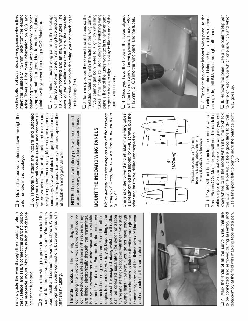
33
switc
h, g
uide
the
wire
thr
ough
the
mou
ntin
g ho
le i
n th
e fu
sela
ge, a
nd T
HE
N c
onne
ct th
e ch
argi
ng p
lug
to
the
rece
ptac
le m
ount
. M
ount
the
sw
itch
and
char
ge
jack
to th
e fu
sela
ge.
❏ 3
. Ref
er t
o th
e w
iring
dia
gram
s in
the
bac
k of
the
m
anua
l fo
r th
e se
rvo
exte
nsio
ns a
nd Y
-har
ness
es
used
. Ins
tall
and
conn
ect t
he w
ires
as s
how
n. W
here
ap
prop
riate
, se
cure
con
nect
ions
bet
wee
n w
ires
with
he
at s
hrin
k tu
bing
.
Th
rott
le
ho
oku
p:
The
w
iring
di
agra
m
for
conn
ectin
g th
e th
rottl
e se
rvos
sho
ws
each
ser
vo
conn
ecte
d to
sep
arat
e ch
anne
ls in
the
rece
iver
. The
y ar
e lin
ked
elec
tron
ical
ly t
hrou
gh t
he t
rans
mitt
er,
but
your
re
ceiv
er
mus
t al
so
have
an
av
aila
ble
chan
nel
for
this
mix
. Fo
r ou
r F
utab
a ra
dio
we
conn
ecte
d on
e en
gine
to
chan
nel 3
and
the
oth
er
engi
ne to
cha
nnel
8 (A
uxili
ary
2). D
epen
ding
on
the
posi
tion
of th
e as
sign
ed m
ixin
g sw
itch,
the
thro
ttles
ca
n be
ope
rate
d se
para
tely
(fo
r sy
nchr
oniz
atio
n tu
ning
and
sta
rtin
g) o
r tog
ethe
r with
the
thro
ttle
stic
k du
ring
fl igh
t. H
owev
er,
if yo
u do
not
hav
e en
ough
av
aila
ble
chan
nels
to
link
the
thro
ttles
thr
ough
the
tr
ansm
itter
, th
ey c
ould
be
linke
d w
ith a
Y-H
arne
ss
and
conn
ecte
d to
the
sam
e ch
anne
l.
❏ 4
. M
ark
the
ends
of
all
the
serv
o w
ires
that
are
to
be
conn
ecte
d an
d re
mov
ed d
urin
g as
sem
bly
and
disa
ssem
bly
at th
e fi e
ld w
ith m
aski
ng ta
pe a
nd a
pen
.
❏ 5
. G
uide
the
rec
eive
r an
tenn
a do
wn
thro
ugh
the
ante
nna
tube
in th
e fu
sela
ge.
❏ 6
. Te
mpo
raril
y at
tach
the
inb
oard
and
out
boar
d w
ing
pane
ls a
nd t
ail t
o th
e fu
sela
ge a
nd c
onne
ct a
ll th
e se
rvo
wire
s. T
urn
on t
he r
adio
and
mak
e su
re
ever
ythi
ng o
pera
tes
corr
ectly
. Mak
e an
y ad
just
men
ts
nece
ssar
y. N
ow w
ould
als
o be
a g
ood
time
to c
onne
ct
the
air
lines
, pr
essu
rize
the
syst
em a
nd o
pera
te t
he
retr
acta
ble
land
ing
gear
as
wel
l.
NO
TE
: The
rec
eive
r ba
ttery
pac
k w
ill b
e m
ount
ed
afte
r th
e no
se-g
unne
r ca
bin
has
been
com
plet
ed.
MO
UN
T T
HE
INB
OA
RD
WIN
G P
AN
EL
S
We’
ve a
lread
y ha
d th
e w
ings
on
and
off t
he fu
sela
ge
a co
uple
of
times
, bu
t no
w i
t’s t
ime
to m
ount
the
m
“for
rea
l.”
One
end
of t
he fo
rwar
d an
d af
t alu
min
um w
ing
tube
s is
alre
ady
drill
ed a
nd ta
pped
for
4-40
scr
ews,
but
the
othe
r en
d ha
s to
be
drill
ed a
nd ta
pped
too.
The
bal
ance
poi
nt is
5"
[127
mm
]fr
om th
e le
adin
g ed
ge o
f the
win
gw
here
it c
onta
cts
the
fuse
lage
.
5"[1
27m
m]
❏ 1
. If
you
will
not
be
bala
ncin
g th
e m
odel
with
a
Gre
at P
lane
s C
.G. M
achi
ne, y
ou w
ill n
eed
to m
ark
the
bala
nce
poin
t on
the
bot
tom
of
the
win
g so
you
will
kn
ow w
here
to
lift
the
mod
el w
hen
it’s
time
to c
heck
th
e C
.G. l
ater
. Now
wou
ld b
e a
good
tim
e to
do
this
. U
se a
fi ne
-poi
nt fe
lt-tip
pen
to m
ark
the
bala
nce
poin
t
on th
e bo
ttom
of b
oth
inbo
ard
win
g pa
nels
whe
re th
ey
mee
t the
fuse
lage
5"
[127
mm
] bac
k fr
om th
e le
adin
g ed
ge.
The
re w
ill b
e m
ore
info
rmat
ion
on C
.G.
and
bala
ncin
g th
e m
odel
lat
er a
fter
asse
mbl
y ha
s be
en
com
plet
ed,
but
it’s
a go
od id
ea t
o m
ark
the
bala
nce
poin
t now
(if
you
won
’t be
usi
ng a
C.G
. Mac
hine
).
❏ 2
. F
it ei
ther
inb
oard
win
g pa
nel
to t
he f
usel
age
with
the
30 x
440
mm
cen
ter
mai
n w
ing
tube
and
bot
h 10
x 3
05m
m f
orw
ard
and
aft
mai
n w
ing
tube
s. T
he
ends
of
the
smal
ler
tube
s th
at h
ave
the
thre
aded
ho
les
shou
ld b
e in
side
the
win
g yo
u ar
e at
tach
ing
to
the
fuse
lage
fi rs
t.
❏ 3
. Tur
n an
d po
sitio
n th
e fo
rwar
d an
d af
t tub
es s
o th
e th
read
ed h
oles
alig
n w
ith th
e ho
les
in th
e w
ing
pane
l. If
you
cann
ot g
et b
oth
hole
s to
alig
n, t
ry s
witc
hing
tu
bes.
If
the
hole
s st
ill d
on’t
alig
n tr
y sw
itchi
ng w
ing
pane
ls. I
f one
of t
he tu
bes
won
’t go
in q
uite
far e
noug
h to
get
the
hole
s to
alig
n, it
is o
kay
to fi
le th
e en
d of
the
tube
as
nece
ssar
y.
❏ 4
. O
nce
you
have
the
hol
es i
n th
e tu
bes
alig
ned
with
the
hole
s in
one
of t
he w
ing
pane
ls, t
hrea
d 4-
40 x
1"
[25m
m] S
HC
S in
to th
e w
ing
pane
l and
the
tube
s.
❏ 5
. Tig
htly
fi t
the
othe
r in
boar
d w
ing
pane
l to
the
fu
sela
ge a
nd tu
bes.
Usi
ng th
e ho
les
in th
e w
ing
pane
l as
a g
uide
, dril
l #43
hol
es th
roug
h bo
th tu
bes.
❏ 6
. Rem
ove
the
pane
l. U
se a
fi ne
-poi
nt fe
lt-tip
pen
to
writ
e on
eac
h tu
be w
hich
one
is w
hich
and
whi
ch
way
goe
s up
.
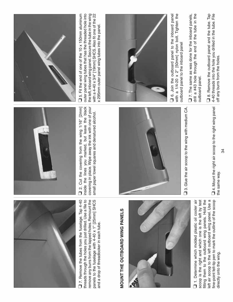
34
❏ 7
. Rem
ove
the
tube
s fr
om t
he f
usel
age.
Tap
4-4
0 th
read
s th
roug
h th
e ho
les
you
just
dril
led.
Use
a fi
le to
re
mov
e an
y bu
rrs
from
the
tapp
ed h
oles
. Rem
ount
the
pane
ls t
o th
e fu
sela
ge w
ith 4
-40
x 1"
[25
mm
] S
HC
S
and
a dr
op o
f thr
eadl
ocke
r in
eac
h tu
be.
MO
UN
T T
HE
OU
TB
OA
RD
WIN
G P
AN
EL
S
❏ 1
. D
eter
min
e w
hich
mol
ded
plas
tic o
il co
oler
air
scoo
p is
the
rig
ht a
nd w
hich
one
is
the
left
by t
est
fi ttin
g th
em t
o th
e ou
tboa
rd w
ing
pane
ls.
Hol
d th
e le
ft ai
r sc
oop
to t
he le
ft ou
tboa
rd w
ing
pane
l. U
se a
fi n
e-po
int f
elt-
tip p
en to
mar
k th
e ou
tline
of t
he s
coop
di
rect
ly o
nto
the
win
g.
❏ 2
. C
ut t
he c
over
ing
from
the
win
g 1/
16"
[2m
m]
insi
de t
he l
ines
you
mar
ked,
but
lea
ve t
he b
lack
co
verin
g in
pla
ce. W
ipe
away
the
ink
with
one
of y
our
smal
l pap
er to
wel
squ
ares
and
den
atur
ed a
lcoh
ol.
❏ 3
. Glu
e th
e ai
r sc
oop
to th
e w
ing
with
med
ium
CA
.
❏ 4
. Mou
nt th
e rig
ht a
ir sc
oop
to th
e rig
ht w
ing
pane
l th
e sa
me
way
.
❏ 5
. Fit
the
end
of o
ne o
f the
10
x 15
0mm
alu
min
um
oute
r pan
el w
ing
tube
s th
at h
as th
e th
read
ed h
ole
into
th
e le
ft, in
boar
d w
ing
pane
l. S
ecur
e th
e tu
be in
the
win
g w
ith a
4-4
0 x
3/4"
[19m
m] S
HC
S. A
lso
fi t o
ne o
f the
22
x 29
5mm
out
er p
anel
win
g tu
bes
into
the
pane
l.
❏ 6
. Jo
in t
he o
utbo
ard
pane
l to
the
inb
oard
pan
el
with
a 1
/4-2
0 x
2" [
50m
m]
nylo
n bo
lt. T
ight
en t
he
outb
oard
pan
el to
the
inbo
ard
pane
l
❏ 7
. The
sam
e as
was
don
e fo
r th
e in
boar
d pa
nels
, dr
ill a
#43
hol
e th
roug
h th
e en
d of
the
tub
e in
the
ou
tboa
rd p
anel
.
❏ 8
. Rem
ove
the
outb
oard
pan
el a
nd t
he t
ube.
Tap
4-
40 th
read
s in
to th
e ho
le y
ou d
rille
d in
the
tube
. File
of
f any
bur
rs fr
om th
e ho
les.
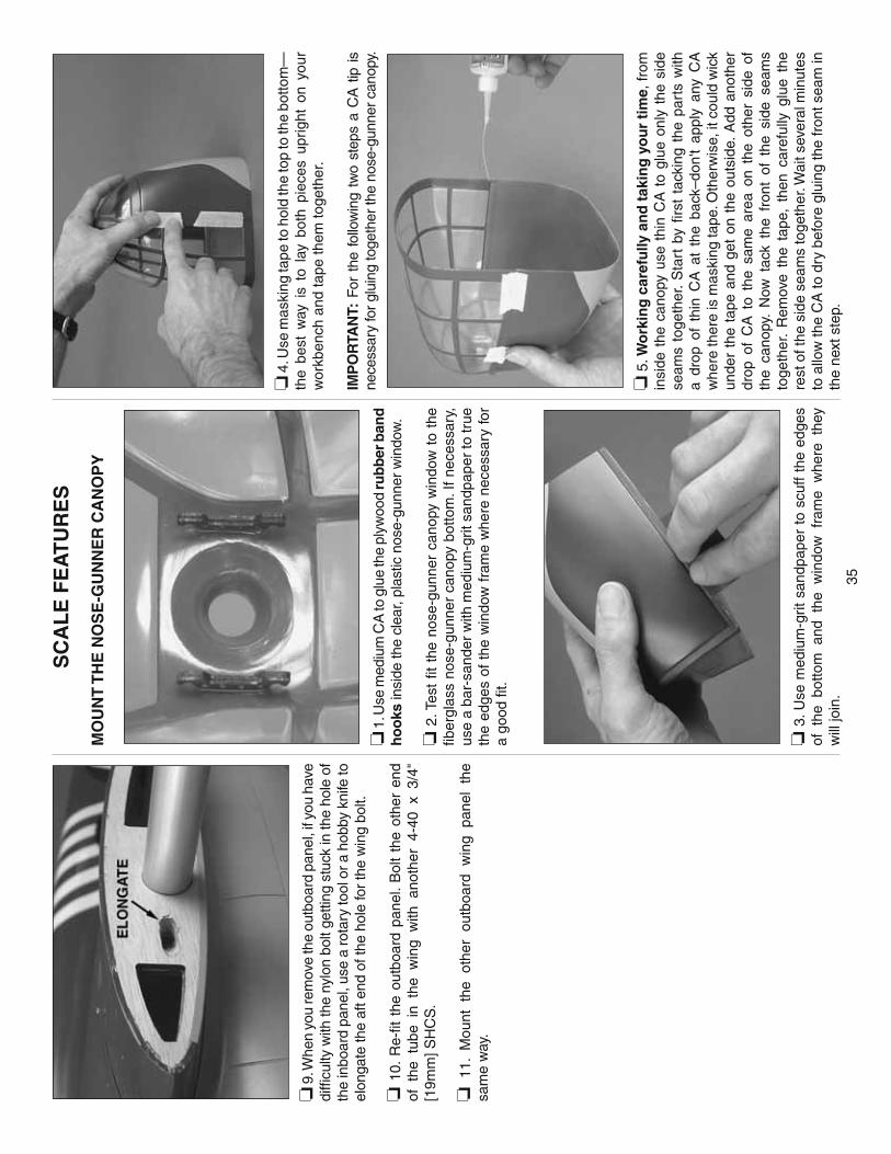
35
❏ 9
. Whe
n yo
u re
mov
e th
e ou
tboa
rd p
anel
, if y
ou h
ave
diffi
culty
with
the
nylo
n bo
lt ge
tting
stu
ck in
the
hole
of
the
inbo
ard
pane
l, us
e a
rota
ry to
ol o
r a h
obby
kni
fe to
el
onga
te th
e af
t end
of t
he h
ole
for
the
win
g bo
lt.
❏ 1
0. R
e-fi t
the
out
boar
d pa
nel.
Bol
t th
e ot
her
end
of t
he t
ube
in t
he w
ing
with
ano
ther
4-4
0 x
3/4"
[1
9mm
] SH
CS
.
❏ 1
1. M
ount
the
oth
er o
utbo
ard
win
g pa
nel
the
sam
e w
ay.
SC
AL
E F
EA
TU
RE
S
MO
UN
T T
HE
NO
SE
-GU
NN
ER
CA
NO
PY
❏ 1
. Use
med
ium
CA
to g
lue
the
plyw
ood
rub
ber
ban
d
ho
oks
insi
de th
e cl
ear,
plas
tic n
ose-
gunn
er w
indo
w.
❏ 2
. Tes
t fi t
the
nos
e-gu
nner
can
opy
win
dow
to
the
fi ber
glas
s no
se-g
unne
r ca
nopy
bot
tom
. If
nece
ssar
y,
use
a ba
r-sa
nder
with
med
ium
-grit
san
dpap
er to
true
th
e ed
ges
of t
he w
indo
w f
ram
e w
here
nec
essa
ry fo
r a
good
fi t.
❏ 3
. Use
med
ium
-grit
san
dpap
er t
o sc
uff
the
edge
s of
the
bot
tom
and
the
win
dow
fra
me
whe
re t
hey
will
join
.
❏ 4
. Use
mas
king
tape
to h
old
the
top
to th
e bo
ttom
—th
e be
st w
ay i
s to
lay
bot
h pi
eces
upr
ight
on
your
w
orkb
ench
and
tape
them
toge
ther
.
IMP
OR
TAN
T: F
or t
he f
ollo
win
g tw
o st
eps
a C
A t
ip i
s ne
cess
ary
for g
luin
g to
geth
er th
e no
se-g
unne
r can
opy.
❏ 5
. Wo
rkin
g c
aref
ully
an
d t
akin
g y
ou
r ti
me,
from
in
side
the
can
opy
use
thin
CA
to
glue
onl
y th
e si
de
seam
s to
geth
er.
Sta
rt b
y fi r
st t
acki
ng t
he p
arts
with
a
drop
of
thin
CA
at
the
back
–don
't ap
ply
any
CA
w
here
ther
e is
mas
king
tape
. Oth
erw
ise,
it c
ould
wic
k un
der
the
tape
and
get
on
the
outs
ide.
Add
ano
ther
dr
op o
f C
A t
o th
e sa
me
area
on
the
othe
r si
de o
f th
e ca
nopy
. N
ow t
ack
the
fron
t of
the
sid
e se
ams
toge
ther
. R
emov
e th
e ta
pe,
then
car
eful
ly g
lue
the
rest
of t
he s
ide
seam
s to
geth
er. W
ait s
ever
al m
inut
es
to a
llow
the
CA
to d
ry b
efor
e gl
uing
the
fron
t sea
m in
th
e ne
xt s
tep.
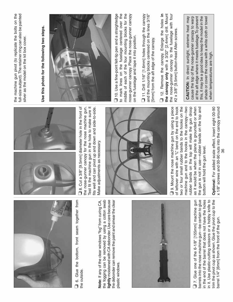
36
❏ 6
. G
lue
the
botto
m,
fron
t se
am t
oget
her
from
th
e ou
tsid
e.
No
te: I
f any
of t
he c
lear
win
dow
s “fo
g” fr
om c
urin
g C
A,
the
fogg
ing
can
be r
emov
ed b
y us
ing
a co
tton
swab
lig
htly
moi
sten
ed w
ith C
A d
ebon
der.
Use
car
e be
caus
e th
e de
bond
er c
an re
mov
e th
e pa
int a
nd s
mea
r the
cle
ar
plas
tic w
indo
ws.
❏ 7
. G
lue
one
of t
he 6
-1/8
" [1
55m
m]
mac
hine
gun
ba
rrel
s in
to th
e no
se m
achi
ne g
un—
be c
erta
in to
glu
e in
the
end
of
the
barr
el t
hat
does
not
hav
e th
e ho
les
in it
. Use
pla
stic
-cut
ting
scis
sors
or
a ho
bby
knife
to
trim
the
pivo
t cup
as
show
n. G
lue
the
pivo
t cup
to th
e ba
rrel
1/4
" [6
mm
] fro
m th
e fr
ont o
f the
gun
.
❏
8. C
ut a
3/8
" [9
.5m
m] d
iam
eter
hol
e in
the
fron
t of
the
nose
-gun
ner
cano
py f
or t
he n
ose
mac
hine
gun
. Te
st fi
t th
e m
achi
ne g
un i
n th
e ho
le t
o m
ake
sure
it
fi ts
wel
l and
can
piv
ot u
p an
d do
wn
and
side
-to-
side
. M
ake
adju
stm
ents
as
nece
ssar
y.
❏ 9
. Mou
nt t
he n
ose
mac
hine
gun
by
usin
g a
piec
e of
lef
tove
r w
ire w
ith a
n “L
” be
nd o
n th
e en
d to
hoo
k tw
o or
fou
r sm
all
rubb
er b
ands
to
the
hook
s on
the
m
achi
ne g
un a
nd t
o th
e ho
oks
in t
he c
anop
y—tw
o ru
bber
ban
ds o
n th
e to
p w
ill m
ake
the
gun
droo
p as
it w
ould
be
whe
n th
e pl
ane
is g
roun
ded
or w
hen
the
gun
is n
ot in
use
—ru
bber
ban
ds o
n th
e to
p an
d bo
ttom
will
hol
d th
e gu
n le
vel.
Op
tio
nal
: F
or a
dded
sca
le e
ffect
, in
sert
eig
ht 0
0-90
x
1/8"
scr
ews
and
00-9
0 nu
ts in
to th
e ca
nopy
aro
und
the
mac
hine
gun
piv
ot (
to r
eplic
ate
the
bolts
on
the
full-
size
sub
ject
). T
he re
tain
er ri
ng c
an a
lso
be p
aint
ed
silv
er a
s th
e m
odel
on
the
kit b
ox c
over
.
Use
th
is p
ho
to fo
r th
e fo
llow
ing
tw
o s
tep
s.
❏ 1
0. U
se a
fi ne
-poi
nt fe
lt-tip
pen
and
a s
trai
ghte
dge
to m
ark
lines
on
the
fuse
lage
cen
tere
d ov
er t
he
mid
dle
of e
ach
of t
he f
our
mou
ntin
g bl
ocks
for
the
no
se-g
unne
r ca
nopy
. Pla
ce t
he n
ose-
gunn
er c
anop
y on
the
fuse
lage
and
tape
it in
to p
ositi
on.
❏ 1
1. D
rill 1
/16"
[1.
6mm
] ho
les
thro
ugh
the
cano
py
and
the
mou
ntin
g bl
ocks
cen
tere
d on
the
line
s 3/
16"
[5m
m] f
rom
the
aft e
dge
of th
e ca
nopy
.
❏ 1
2. R
emov
e th
e ca
nopy
. E
nlar
ge t
he h
oles
in
th
e ca
no
py
on
ly w
ith a
3/3
2" [
2.4m
m]
drill
. M
ount
th
e no
se-g
unne
r ca
nopy
to
the
fuse
lage
with
fou
r #2
x 3
/8"
[9.5
mm
] but
ton-
head
Alle
n sc
rew
s.
CA
UT
ION
: In
dire
ct s
unlig
ht,
extr
eme
heat
may
ca
use
the
top
of t
he n
ose-
gunn
er c
anop
y to
war
p at
the
aft e
dge
whe
re it
mee
ts fu
sela
ge.T
o pr
even
t th
is, i
t may
be
a go
od id
ea to
kee
p th
e m
odel
in th
e sh
ade
or c
over
the
nose
with
a w
hite
clo
th o
r tow
el
whe
n te
mpe
ratu
res
are
high
.
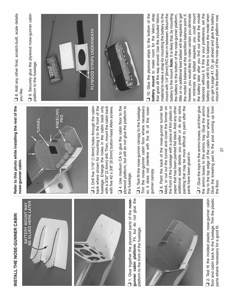
37
INS
TAL
L T
HE
NO
SE
-GU
NN
ER
CA
BIN
❏ 1
. G
lue
toge
ther
the
ply
woo
d pa
rts
of t
he n
ose
-g
un
ner
cab
in p
latf
orm
. F
it, b
ut d
o no
t gl
ue t
he
plat
form
to th
e fr
ont o
f the
fuse
lage
.
❏ 2
. Te
st fi
t th
e m
olde
d pl
astic
nos
e-gu
nner
cab
in
fl oor
and
cab
in b
ack
to t
he f
usel
age.
Trim
the
pla
stic
pa
rts
whe
re n
eces
sary
for
a go
od fi
t.
Ref
er t
o t
his
ph
oto
wh
ile in
stal
ling
th
e re
st o
f th
e n
ose
-gu
nn
er c
abin
.
❏ 3
. Dril
l fi v
e 1/
16"
[1.6
mm
] ho
les
thro
ugh
the
cabi
n ba
ck w
here
sho
wn
for
mou
ntin
g it
to t
he f
ront
of
the
fuse
lage
. E
nlar
ge t
he h
oles
in
the
cabi
n ba
ck o
nly
with
a 3
/32"
[2.4
mm
] dril
l. T
hen,
mou
nt th
e ca
bin
back
w
ith fi
ve #
2 x
3/8"
[9.5
mm
] but
ton-
head
Alle
n sc
rew
s.
❏ 4
. U
se m
ediu
m C
A t
o gl
ue t
he c
abin
fl o
or t
o th
e pl
ywoo
d pl
atfo
rm, b
ut s
till d
o no
t glu
e th
e pl
atfo
rm to
th
e fu
sela
ge.
❏ 5
. Tes
t fi t
the
nose
-gun
ner
cano
py to
the
fuse
lage
. Tr
im t
he n
ose-
gunn
er c
abin
fl o
or w
here
nec
essa
ry
so i
t do
es n
ot i
nter
fere
with
the
fi t
of t
he n
ose-
gunn
er c
anop
y.
❏ 6
. P
aint
the
bac
k of
the
nos
e-gu
nner
tun
nel
fl at
blac
k, o
r cu
t ou
t th
e tu
nnel
and
cov
er t
he f
orm
er o
n th
e fr
ont o
f the
fuse
lage
with
a p
iece
of t
hin
plas
tic o
r pa
per
that
has
bee
n pa
inte
d fl a
t bla
ck. A
dd a
ny o
ther
ad
ditio
nal
scal
e de
tails
you
pre
fer
or d
o an
y ex
tra
pain
ting
that
may
be
mor
e di
ffi cu
lt to
pai
nt a
fter
the
part
s ha
ve b
een
glue
d in
.
❏ 7
. Glu
e th
e to
ps to
the
amm
o bo
xes,
and
then
glu
e th
e am
mo
boxe
s to
the
am
mo
tray
. G
lue
the
amm
o tr
ay t
o th
e to
p ed
ge o
f th
e ca
bin
fl oor
whe
re s
how
n.
Glu
e th
e kn
eelin
g pa
d to
the
pos
t co
min
g up
fro
m
the
fl oor
.
❏ 8
. Add
any
oth
er fi
nal
, sc
ratc
h-bu
ilt,
scal
e de
tails
yo
u lik
e.
❏ 9
. S
ecur
ely
glue
the
ply
woo
d no
se-g
unne
r ca
bin
plat
form
to th
e fu
sela
ge.
❏ 1
0. G
lue
the
plyw
ood
strip
s to
the
bot
tom
of
the
bat
tery
mo
un
t to
mak
e ro
om f
or t
he V
elcr
o st
rap
that
goe
s al
l the
way
aro
und.
Use
the
incl
uded
Vel
cro
mat
eria
l to
mak
e a
stra
p fo
r mou
ntin
g th
e ba
ttery
to th
e m
ount
with
1/4
" [6m
m] R
/C fo
am in
bet
wee
n. M
ount
the
batte
ry to
the
mou
nt. N
ote
: It i
s lik
ely
that
, by
mou
ntin
g th
e ba
ttery
to th
e bo
ttom
of t
he n
ose-
gunn
er p
latfo
rm,
little
or
no a
dditi
onal
lead
bal
last
will
be
requ
ired
to g
et
the
mod
el to
bal
ance
at t
he s
peci
fi ed
bala
nce
poin
t. If,
ho
wev
er, y
ou w
ould
like
to m
ake
cert
ain
you
elim
inat
e or
min
imiz
e an
y ba
llast
req
uire
d, y
ou c
ould
mou
nt
the
batte
ry l
ater
afte
r yo
u fi n
d ou
t w
here
the
mod
el
bala
nces
with
out
it. I
f th
is i
s yo
ur p
refe
renc
e, s
et t
he
batte
ry a
side
unt
il it’
s tim
e to
bal
ance
the
mod
el w
hen
you
get t
o pa
ge 4
1. O
r, go
ahe
ad a
nd g
lue
the
batte
ry
mou
nt to
the
botto
m o
f the
nos
e-gu
nner
pla
tform
now
.

38
MO
UN
T T
HE
TO
P T
UR
RE
T A
ND
MA
CH
INE
GU
NS
❏ 1
. Glu
e tw
o 6-
1/8"
[15
5mm
] m
achi
ne g
un b
arre
ls
into
eac
h of
the
two
top
turr
et m
achi
ne g
uns.
❏ 2
. Pla
ce th
e to
p tu
rret
mac
hine
gun
s on
top
of th
e fu
sela
ge s
o th
e af
t ve
rtic
al b
rack
et i
s 5"
[12
7mm
] fr
om t
he o
peni
ng f
or t
he c
ockp
it an
d so
the
gun
s ar
e ce
nter
ed f
rom
sid
e-to
-sid
e. P
ush
dow
n on
the
m
achi
ne g
uns
hard
eno
ugh
to m
ark
the
bals
a un
der
the
cove
ring.
❏ 3
. U
sing
the
mar
ks i
n th
e to
p of
the
fus
elag
e as
a
guid
e, u
se a
str
aigh
tedg
e to
cut
the
cov
erin
g fr
om
the
top
of th
e fu
sela
ge s
o th
at th
e gu
ns w
ill b
e gl
ued
dire
ctly
to b
alsa
.
❏ 4
. San
d th
e pa
int f
rom
the
botto
m o
f the
top
turr
et
mac
hine
gun
mou
ntin
g br
acke
ts.
Sec
urel
y gl
ue t
he
mac
hine
gun
s to
the
top
of th
e fu
sela
ge.
❏ 5
. P
ositi
on t
he t
op t
urre
t ca
nopy
on
the
fuse
lage
ov
er th
e gu
ns. C
ente
r the
ope
ning
s in
the
turr
et c
anop
y on
the
guns
. The
n, u
se a
fi ne
-poi
nt fe
lt-tip
pen
to m
ark
the
outli
ne o
f the
can
opy
dire
ctly
ont
o th
e fu
sela
ge.
❏ 6
. Cut
the
cov
erin
g 1/
16"
[1-2
mm
] in
side
the
line
yo
u m
arke
d al
l the
way
aro
und.
Cut
ano
ther
line
1/1
6"
[1-2
mm
] ins
ide
the
fi rst
. Rem
ove
the
strip
of c
over
ing
so th
e tu
rret
will
be
glue
d di
rect
ly to
bal
sa.
❏ 7
. P
ositi
on t
he t
urre
t ca
nopy
on
the
fuse
lage
so
the
gun
barr
els
will
be
cent
ered
in
the
open
ings
an
d th
e ca
nopy
will
be
cent
ered
ove
r th
e cu
tout
in
the
cove
ring.
Car
eful
ly u
se t
hin
CA
to
glue
the
tur
ret
cano
py to
the
fuse
lage
.
FIN
ISH
TH
E T
AIL
-GU
NN
ER
CA
BIN
❏ 1
. Te
st-fi
t, tr
im i
f ne
cess
ary,
and
the
n gl
ue t
he
mol
ded
plas
tic t
ail
gu
nn
er b
ulk
hea
d,
arm
or
shie
ld
and
bra
cket
mo
un
t int
o po
sitio
n. U
se fo
am-s
afe
CA
or
epox
y to
glu
e th
e ta
il-gu
nner
pilo
t fi g
ure
into
pos
ition
.
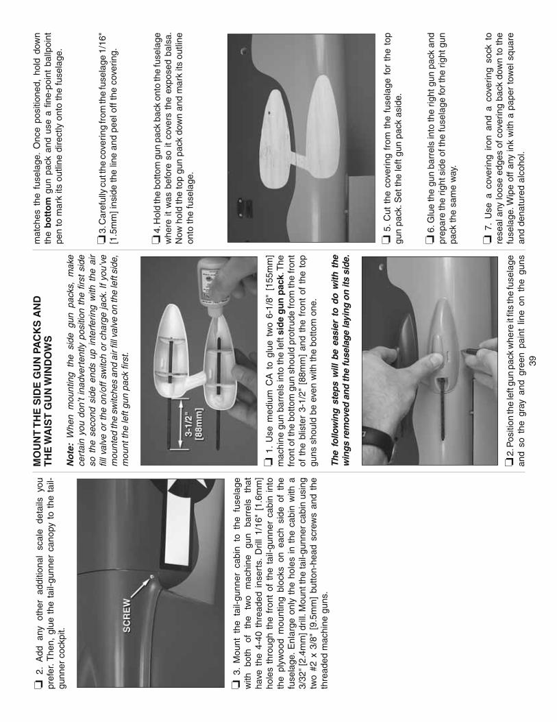
39
❏ 2
. A
dd
any
othe
r ad
ditio
nal
scal
e de
tails
yo
u pr
efer
. The
n, g
lue
the
tail-
gunn
er c
anop
y to
the
tai
l-gu
nner
coc
kpit.
❏ 3
. M
ount
the
tai
l-gun
ner
cabi
n to
the
fus
elag
e w
ith
both
of
th
e tw
o m
achi
ne
gun
barr
els
that
ha
ve t
he 4
-40
thre
aded
ins
erts
. D
rill
1/16
" [1
.6m
m]
hole
s th
roug
h th
e fr
ont
of t
he t
ail-g
unne
r ca
bin
into
th
e pl
ywoo
d m
ount
ing
bloc
ks o
n ea
ch s
ide
of t
he
fuse
lage
. E
nlar
ge o
nly
the
hole
s in
the
cab
in w
ith a
3/
32"
[2.4
mm
] dril
l. M
ount
the
tail-
gunn
er c
abin
usi
ng
two
#2 x
3/8
" [9
.5m
m]
butto
n-he
ad s
crew
s an
d th
e th
read
ed m
achi
ne g
uns.
MO
UN
T T
HE
SID
E G
UN
PA
CK
S A
ND
TH
E W
AIS
T G
UN
WIN
DO
WS
No
te:
Whe
n m
ount
ing
the
side
gun
pac
ks,
mak
e ce
rtai
n yo
u do
n’t
inad
vert
ently
pos
ition
the
fi r
st s
ide
so t
he s
econ
d si
de e
nds
up i
nter
ferin
g w
ith t
he a
ir fi l
l val
ve o
r th
e on
/off
switc
h or
cha
rge
jack
. If
you’
ve
mou
nted
the
switc
hes
and
air fi
ll v
alve
on
the
left
side
, m
ount
the
left
gun
pack
fi rs
t.
❏ 1
. U
se m
ediu
m C
A t
o gl
ue t
wo
6-1/
8" [
155m
m]
mac
hine
gun
bar
rels
into
the
left
sid
e g
un
pac
k. T
he
fron
t of t
he b
otto
m g
un s
houl
d pr
otru
de fr
om th
e fr
ont
of t
he b
liste
r 3-
1/2"
[88
mm
] an
d th
e fr
ont
of t
he t
op
guns
sho
uld
be e
ven
with
the
botto
m o
ne.
The
follo
win
g st
eps
will
be
easi
er t
o do
with
the
w
ings
rem
oved
and
the
fuse
lag
e la
ying
on
its s
ide.
❏ 2
. Pos
ition
the
left
gun
pack
whe
re it
fi ts
the
fuse
lage
an
d so
the
gra
y an
d gr
een
pain
t lin
e on
the
gun
s
mat
ches
the
fus
elag
e. O
nce
posi
tione
d, h
old
dow
n th
e b
ott
om
gun
pac
k an
d us
e a
fi ne-
poin
t ba
llpoi
nt
pen
to m
ark
its o
utlin
e di
rect
ly o
nto
the
fuse
lage
.
❏ 3
. Car
eful
ly c
ut th
e co
verin
g fr
om th
e fu
sela
ge 1
/16"
[1
.5m
m] i
nsid
e th
e lin
e an
d pe
el o
ff th
e co
verin
g.
❏ 4
. Hol
d th
e bo
ttom
gun
pac
k ba
ck o
nto
the
fuse
lage
w
here
it w
as b
efor
e so
it c
over
s th
e ex
pose
d ba
lsa.
N
ow h
old
the
top
gun
pack
dow
n an
d m
ark
its o
utlin
e on
to th
e fu
sela
ge.
❏ 5
. C
ut t
he c
over
ing
from
the
fus
elag
e fo
r th
e to
p gu
n pa
ck. S
et th
e le
ft gu
n pa
ck a
side
.
❏ 6
. Glu
e th
e gu
n ba
rrel
s in
to th
e rig
ht g
un p
ack
and
prep
are
the
right
sid
e of
the
fuse
lage
for t
he r
ight
gun
pa
ck th
e sa
me
way
.
❏ 7
. U
se a
cov
erin
g iro
n an
d a
cove
ring
sock
to
rese
al a
ny lo
ose
edge
s of
cov
erin
g ba
ck d
own
to th
e fu
sela
ge. W
ipe
off
any
ink
with
a p
aper
tow
el s
quar
e an
d de
natu
red
alco
hol.

40
Do
not g
lue
on th
e si
de g
un p
acks
yet
. Pre
pare
the
fuse
lage
for
glu
ing
on t
he w
aist
gun
win
dow
s as
de
scrib
ed b
elow
. Wai
ting
to g
lue
on t
he s
ide
gun
pack
s an
d w
aist
gun
s un
til a
fter
the
fuse
lage
has
be
en p
repa
red
for
them
mak
es it
eas
ier
to la
y th
e fu
sela
ge o
n its
sid
e.
❏ 8
. Glu
e on
e of
the
4-7
/8"
[125
mm
] w
aist
mac
hine
gu
n ba
rrel
s in
to th
e le
ft w
aist
gun
win
dow
as
show
n.
❏ 9
. Sam
e as
for t
he to
p gu
n tu
rret
and
the
gun
pack
s,
use
a fi n
e-po
int b
allp
oint
pen
to m
ark
the
outli
ne o
f the
w
aist
gun
win
dow
dire
ctly
ont
o th
e fu
sela
ge. C
ut a
nd
rem
ove
the
cove
ring
1/16
" [1
.5m
m] i
nsid
e th
e lin
e.
❏ 1
0. P
repa
re t
he r
ight
wai
st g
un w
indo
w a
nd t
he
right
sid
e of
the
fuse
lage
the
sam
e w
ay.
❏ 1
1. P
aint
the
insi
de e
dges
of t
he w
indo
w o
peni
ngs
for
the
wai
st g
uns
fl at b
lack
.
No
w b
ack
to t
he
gu
n p
acks
…
❏ 1
2. P
lace
the
left
gun
pack
on
the
fuse
lage
. Firs
t gl
ue t
he b
otto
m,
and
then
the
top
gun
pac
k do
wn
usin
g th
in C
A w
ith a
CA
app
licat
or ti
p.
❏ 1
3. G
lue
on t
he r
ight
gun
pac
k, t
hen
the
right
an
d le
ft w
aist
gun
win
dow
s, w
ith t
hin
CA
and
a C
A
appl
icat
or ti
p.
MO
UN
T T
HE
AD
F “
FO
OT
BA
LL”
AN
TE
NN
A
The
AD
F f
ootb
all
ante
nna
is a
ttach
ed t
o th
e m
odel
w
ith m
agne
ts.
Thi
s w
ay i
t ca
n be
eas
ily r
emov
ed
for
tran
spor
tatio
n.
❏ 1
. U
se t
he p
lyw
ood
tem
plat
e as
a g
uide
to
cut
hole
s in
the
fus
elag
e fo
r th
e m
agne
ts w
ith a
3/1
6"
[4.8
mm
] bra
ss tu
be s
harp
ened
on
the
end
or a
3/1
6"
[4.8
mm
] dr
ill.
The
hol
es s
houl
d be
cen
tere
d ov
er
the
mid
dle
strin
ger
in t
he b
otto
m o
f th
e fu
sela
ge.
No
te:
The
E
xecu
tive
Sw
eet
had
the
ante
nna
on
the
botto
m o
f th
e fu
sela
ge,
but
som
e B
-25s
had
the
fo
otba
ll an
tenn
a in
oth
er lo
catio
ns. Y
ou c
an m
ount
the
ante
nna
whe
reve
r yo
u pr
efer
.
❏ 2
. S
tick
the
two
mag
nets
to
the
othe
r m
agne
ts
alre
ady
glue
d in
the
ant
enna
so
you’
ll kn
ow w
hich
w
ay to
glu
e th
em in
.
❏ 3
. Use
med
ium
-grit
san
dpap
er t
o lig
htly
san
d th
e bo
ttom
of
each
mag
net
so g
lue
will
adh
ere.
Mak
ing
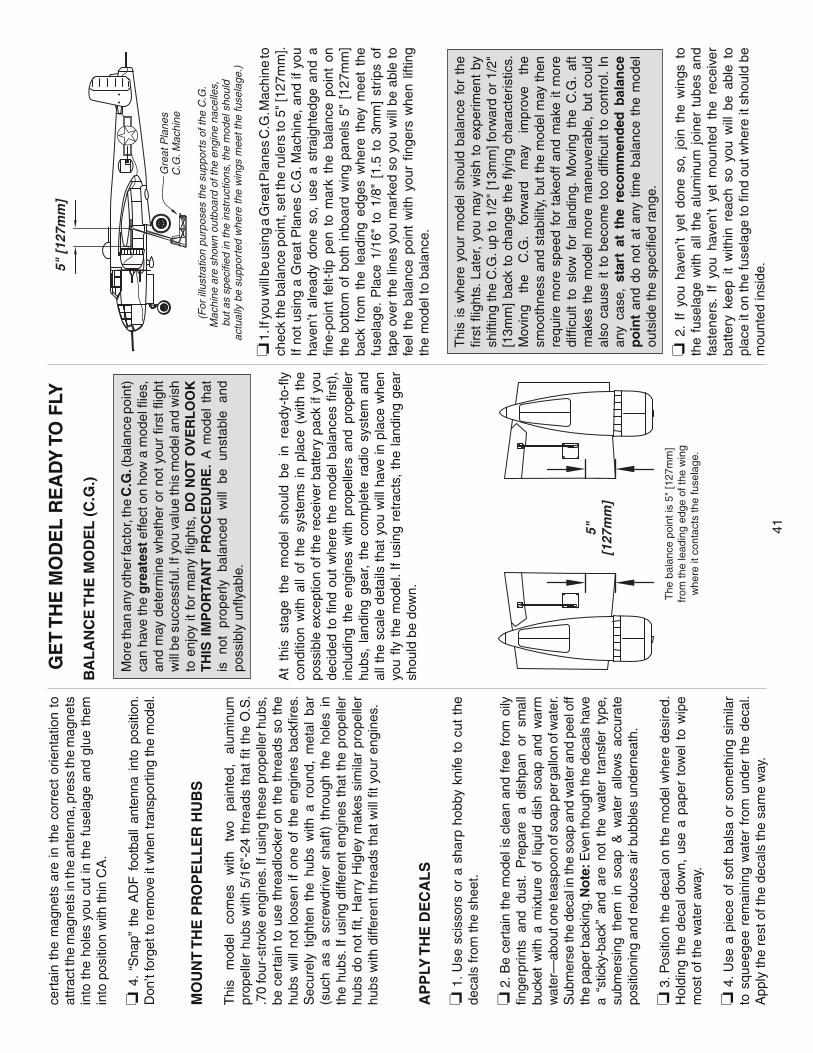
41
cert
ain
the
mag
nets
are
in t
he c
orre
ct o
rient
atio
n to
at
trac
t the
mag
nets
in th
e an
tenn
a, p
ress
the
mag
nets
in
to t
he h
oles
you
cut
in t
he f
usel
age
and
glue
the
m
into
pos
ition
with
thin
CA
.
❏ 4
. “S
nap”
the
AD
F f
ootb
all
ante
nna
into
pos
ition
. D
on’t
forg
et to
rem
ove
it w
hen
tran
spor
ting
the
mod
el.
MO
UN
T T
HE
PR
OP
EL
LE
R H
UB
S
Thi
s m
odel
co
mes
w
ith
two
pain
ted,
al
umin
um
prop
elle
r hu
bs w
ith 5
/16"
-24
thre
ads
that
fi t
the
O.S
. .7
0 fo
ur-s
trok
e en
gine
s. If
usi
ng th
ese
prop
elle
r hub
s,
be c
erta
in t
o us
e th
read
lock
er o
n th
e th
read
s so
the
hu
bs w
ill n
ot l
oose
n if
one
of t
he e
ngin
es b
ackfi
res
. S
ecur
ely
tight
en t
he h
ubs
with
a r
ound
, m
etal
bar
(s
uch
as a
scr
ewdr
iver
sha
ft) t
hrou
gh t
he h
oles
in
the
hubs
. If
usin
g di
ffere
nt e
ngin
es t
hat
the
prop
elle
r hu
bs d
o no
t fi t
, H
arry
Hig
ley
mak
es s
imila
r pr
opel
ler
hubs
with
diff
eren
t thr
eads
that
will
fi t y
our
engi
nes.
AP
PLY
TH
E D
EC
AL
S
❏ 1
. Use
sci
ssor
s or
a s
harp
hob
by k
nife
to
cut
the
deca
ls fr
om th
e sh
eet.
❏ 2
. Be
cert
ain
the
mod
el is
cle
an a
nd f
ree
from
oily
fi n
gerp
rints
and
dus
t. P
repa
re a
dis
hpan
or
smal
l bu
cket
with
a m
ixtu
re o
f liq
uid
dish
soa
p an
d w
arm
w
ater
—ab
out o
ne te
aspo
on o
f soa
p pe
r gal
lon
of w
ater
. S
ubm
erse
the
deca
l in
the
soap
and
wat
er a
nd p
eel o
ff th
e pa
per b
acki
ng. N
ote
: Eve
n th
ough
the
deca
ls h
ave
a “s
ticky
-bac
k” a
nd a
re n
ot t
he w
ater
tra
nsfe
r ty
pe,
subm
ersi
ng t
hem
in
soap
& w
ater
allo
ws
accu
rate
po
sitio
ning
and
red
uces
air
bubb
les
unde
rnea
th.
❏ 3
. Pos
ition
the
deca
l on
the
mod
el w
here
des
ired.
H
oldi
ng t
he d
ecal
dow
n, u
se a
pap
er t
owel
to
wip
e m
ost o
f the
wat
er a
way
.
❏ 4
. Use
a p
iece
of
soft
bals
a or
som
ethi
ng s
imila
r to
squ
eege
e re
mai
ning
wat
er f
rom
und
er t
he d
ecal
. A
pply
the
rest
of t
he d
ecal
s th
e sa
me
way
.
GE
T T
HE
MO
DE
L R
EA
DY
TO
FLY
BA
LA
NC
E T
HE
MO
DE
L (
C.G
.)
Mor
e th
an a
ny o
ther
fact
or, t
he C
.G. (
bala
nce
poin
t)
can
have
the
gre
ates
t effe
ct o
n ho
w a
mod
el fl
ies,
an
d m
ay d
eter
min
e w
heth
er o
r no
t yo
ur fi
rst
fl igh
t w
ill b
e su
cces
sful
. If y
ou v
alue
this
mod
el a
nd w
ish
to e
njoy
it fo
r m
any
fl igh
ts,
DO
NO
T O
VE
RL
OO
K
TH
IS I
MP
OR
TAN
T P
RO
CE
DU
RE
. A
mod
el t
hat
is
not
prop
erly
ba
lanc
ed
will
be
un
stab
le
and
poss
ibly
unfl
yab
le.
At
this
sta
ge t
he m
odel
sho
uld
be i
n re
ady-
to-fl
y
cond
ition
with
all
of t
he s
yste
ms
in p
lace
(w
ith t
he
poss
ible
exc
eptio
n of
the
rece
iver
bat
tery
pac
k if
you
deci
ded
to fi
nd
out
whe
re t
he m
odel
bal
ance
s fi r
st),
in
clud
ing
the
engi
nes
with
pro
pelle
rs a
nd p
rope
ller
hubs
, la
ndin
g ge
ar,
the
com
plet
e ra
dio
syst
em a
nd
all t
he s
cale
det
ails
tha
t yo
u w
ill h
ave
in p
lace
whe
n yo
u fl y
the
mod
el. I
f us
ing
retr
acts
, th
e la
ndin
g ge
ar
shou
ld b
e do
wn. The
bal
ance
poi
nt is
5"
[127
mm
]fr
om th
e le
adin
g ed
ge o
f the
win
gw
here
it c
onta
cts
the
fuse
lage
.
5"[1
27m
m]
5" [
127m
m]
(For
illu
stra
tion
purp
oses
the
supp
orts
of t
he C
.G.
Mac
hine
are
sho
wn
outb
oard
of t
he e
ngin
e na
celle
s,
but a
s sp
ecifi
ed in
the
inst
ruct
ions
, the
mod
el s
houl
dac
tual
ly b
e su
ppor
ted
whe
re th
e w
ings
mee
t the
fuse
lage
.)
Gre
at P
lane
sC
.G. M
achi
ne
❏ 1
. If y
ou w
ill b
e us
ing
a G
reat
Pla
nes
C.G
. Mac
hine
to
chec
k th
e ba
lanc
e po
int,
set t
he r
uler
s to
5"
[127
mm
]. If
not u
sing
a G
reat
Pla
nes
C.G
. Mac
hine
, and
if y
ou
have
n’t
alre
ady
done
so,
use
a s
trai
ghte
dge
and
a fi n
e-po
int
felt-
tip p
en t
o m
ark
the
bala
nce
poin
t on
th
e bo
ttom
of
both
inbo
ard
win
g pa
nels
5"
[127
mm
] ba
ck f
rom
the
lea
ding
edg
es w
here
the
y m
eet
the
fuse
lage
. P
lace
1/1
6" t
o 1/
8" [
1.5
to 3
mm
] st
rips
of
tape
ove
r th
e lin
es y
ou m
arke
d so
you
will
be
able
to
feel
the
bal
ance
poi
nt w
ith y
our
fi nge
rs w
hen
liftin
g th
e m
odel
to b
alan
ce.
Thi
s is
whe
re y
our
mod
el s
houl
d ba
lanc
e fo
r th
e fi r
st fl
ight
s. L
ater
, yo
u m
ay w
ish
to e
xper
imen
t by
sh
iftin
g th
e C
.G. u
p to
1/2
" [1
3mm
] for
war
d or
1/2
" [1
3mm
] ba
ck t
o ch
ange
the
fl y
ing
char
acte
ristic
s.
Mov
ing
the
C.G
. fo
rwar
d m
ay
impr
ove
the
smoo
thne
ss a
nd s
tabi
lity,
but
the
mod
el m
ay th
en
requ
ire m
ore
spee
d fo
r ta
keof
f an
d m
ake
it m
ore
diffi
cult
to s
low
for
lan
ding
. M
ovin
g th
e C
.G.
aft
mak
es t
he m
odel
mor
e m
aneu
vera
ble,
but
cou
ld
also
cau
se it
to
beco
me
too
diffi
cult
to c
ontr
ol. I
n an
y ca
se,
star
t at
th
e re
com
men
ded
bal
ance
p
oin
t an
d do
not
at
any
time
bala
nce
the
mod
el
outs
ide
the
spec
ifi ed
ran
ge.
❏ 2
. If
you
have
n’t
yet
done
so,
joi
n th
e w
ings
to
the
fuse
lage
with
all
the
alum
inum
joi
ner
tube
s an
d fa
sten
ers.
If
you
have
n’t
yet
mou
nted
the
rec
eive
r ba
ttery
kee
p it
with
in r
each
so
you
will
be
able
to
plac
e it
on th
e fu
sela
ge to
fi nd
out
whe
re it
sho
uld
be
mou
nted
insi
de.

42
❏ 3
. With
all
part
s of
the
mod
el in
stal
led,
the
mod
el
read
y to
fl y
(le
ss r
ecei
ver
batte
ry),
the
lan
ding
gea
r do
wn
and
an e
mpt
y fu
el t
ank,
pla
ce t
he m
odel
on
a G
reat
Pla
nes
CG
Mac
hine
, or
lift
it w
ith y
our
fi nge
rs
on th
e ba
lanc
e po
int m
arke
d by
the
thin
str
ips
of ta
pe
on th
e bo
ttom
of t
he w
ings
.
❏ 4
. If t
he ta
il dr
ops,
the
mod
el is
“tai
l hea
vy” a
nd th
e ba
ttery
pac
k m
ust b
e m
ount
ed fo
rwar
d or
wei
ght m
ust
be a
dded
to
the
nose
to
bala
nce.
If
the
nose
dro
ps,
the
mod
el is
“no
se h
eavy
” and
the
batte
ry p
ack
mus
t be
mou
nted
aft
or w
eigh
t mus
t be
adde
d to
the
tail
to
bala
nce.
If y
ou h
aven
’t ye
t mou
nted
the
batte
ry p
ack,
pl
ace
it on
top
of th
e fu
sela
ge to
see
whe
re it
sho
uld
be m
ount
ed i
nsid
e to
ach
ieve
the
per
fect
bal
ance
po
int
with
out
havi
ng t
o ad
d an
y ad
ditio
nal
balla
st.
If yo
u al
read
y m
ount
ed t
he b
atte
ry,
or i
f ad
ditio
nal
wei
ght
is r
equi
red,
use
Gre
at P
lane
s (G
PM
Q44
85)
“stic
k-on
” le
ad. T
he b
est
plac
e to
add
stic
k-on
nos
e w
eigh
t is
to
the
botto
m o
f th
e no
se-g
unne
r pl
atfo
rm.
The
bes
t pl
ace
to a
dd t
ail
wei
ght
is i
nsid
e th
e ve
ry
back
of
the
fuse
lage
beh
ind
the
horiz
onta
l sta
biliz
er.
Beg
in b
y pl
acin
g in
crem
enta
lly in
crea
sing
am
ount
s of
w
eigh
t on
the
fuse
lage
ove
r th
e lo
catio
n w
here
it w
ill
be p
erm
anen
tly a
ttach
ed i
nsid
e th
e m
odel
unt
il yo
u ca
n ge
t it t
o ba
lanc
e. O
nce
you
have
det
erm
ined
the
amou
nt o
f wei
ght r
equi
red
(or t
he b
atte
ry p
ositi
onin
g),
it ca
n be
per
man
ently
atta
ched
.
❏ 5
. If
you
have
n’t
yet
done
so,
mou
nt t
he b
atte
ry
pack
in
side
th
e fu
sela
ge,
or
atta
ch
any
requ
ired
lead
bal
last
insi
de t
he n
ose
or t
ail.
No
te:
Do
not
rely
up
on t
he a
dhes
ive
on t
he b
ack
of t
he le
ad w
eigh
t to
pe
rman
ently
hol
d it
in p
lace
. Ove
r tim
e, th
e ad
hesi
ve
may
w
eake
n ca
usin
g th
e w
eigh
t to
fa
ll of
f. U
se
#2 s
heet
met
al s
crew
s, R
TV
sili
cone
or
epox
y to
pe
rman
ently
hol
d th
e w
eigh
t in
plac
e.
❏ 6
. Con
nect
the
rece
iver
bat
tery
to th
e on
/off
switc
h us
ing
a se
rvo
exte
nsio
n if
nece
ssar
y. S
ecur
e th
e co
nnec
tions
with
hea
t shr
ink
tubi
ng.
❏ 7
. IM
PO
RTA
NT:
Onc
e yo
u’ve
mou
nted
the
batte
ry
or a
dded
any
add
ition
al w
eigh
t, re
chec
k th
e C
.G.
afte
r it
has
been
inst
alle
d.
BA
LA
NC
E T
HE
MO
DE
L L
AT
ER
AL
LY
❏ 1
. With
the
win
g le
vel,
have
an
assi
stan
t he
lp y
ou
lift t
he m
odel
und
er th
e m
iddl
e of
the
fuse
lage
beh
ind
the
nose
-gun
ner
cano
py a
nd u
nder
the
tai
l-gun
ner
cock
pit.
Do
this
sev
eral
tim
es.
❏ 2
. If o
ne w
ing
alw
ays
drop
s w
hen
you
lift t
he m
odel
, it
mea
ns t
hat
side
is h
eavy
. Bal
ance
the
air
plan
e by
ad
ding
wei
ght
to t
he o
ther
win
g tip
. A
n a
irp
lan
e th
at h
as b
een
lat
eral
ly b
alan
ced
will
tra
ck b
ette
r in
fl ig
ht
and
mai
nta
in i
ts h
ead
ing
bet
ter
du
rin
g
man
euve
rs w
hen
th
e p
lan
e is
clim
bin
g.
PR
EF
LIG
HT
CH
EC
K T
HE
CO
NT
RO
L D
IRE
CT
ION
S
❏ 1
. Tur
n on
the
tran
smitt
er a
nd r
ecei
ver
and
cent
er
the
trim
s. I
f ne
cess
ary,
rem
ove
the
serv
o ar
ms
from
th
e se
rvos
and
rep
ositi
on th
em s
o th
ey a
re c
ente
red.
R
eins
tall
the
scre
ws
that
hol
d on
the
serv
o ar
ms.
❏ 2
. With
the
tra
nsm
itter
and
rec
eive
r st
ill o
n, c
heck
al
l th
e co
ntro
l su
rfac
es t
o se
e if
they
are
cen
tere
d.
If ne
cess
ary,
adj
ust
the
clev
ises
on
the
push
rods
to
cent
er th
e co
ntro
l sur
face
s.
FU
LL T
HR
OT
TLE
RU
DD
ER
S M
OV
E R
IGH
T
ELE
VAT
OR
MO
VE
S U
PR
IGH
T A
ILE
RO
N M
OV
ES
UP
LEF
T A
ILE
RO
N M
OV
ES
DO
WN
4-C
HA
NN
EL
RA
DIO
SE
TU
P(S
TAN
DA
RD
MO
DE
2)
❏ 3
. M
ake
cert
ain
that
the
con
trol
sur
face
s an
d th
e ca
rbur
etor
res
pond
in
the
corr
ect
dire
ctio
n as
sh
own
in t
he d
iagr
am. I
f an
y of
the
con
trol
s re
spon
d in
the
wro
ng d
irect
ion,
use
the
ser
vo r
ever
sing
in
the
tran
smitt
er t
o re
vers
e th
e se
rvos
con
nect
ed t
o th
ose
cont
rols
. B
e ce
rtai
n th
e co
ntro
l su
rfac
es h
ave
rem
aine
d ce
nter
ed. A
djus
t if n
eces
sary
.

43
SE
T T
HE
CO
NT
RO
L T
HR
OW
S
Use
a
Gre
at
Pla
nes
Acc
uThr
ow
or
a ru
ler
to
accu
rate
ly m
easu
re a
nd s
et th
e co
ntro
l thr
ow o
f eac
h co
ntro
l sur
face
as
indi
cate
d in
the
char
t tha
t fol
low
s. If
yo
ur r
adio
doe
s no
t ha
ve d
ual r
ates
, w
e re
com
men
d se
tting
the
thro
ws
at th
e lo
w r
ate
setti
ng.
NO
TE
: For
the
aile
rons
, th
e th
row
s ar
e m
easu
red
at
the
wid
est
par
t (a
t the
roo
t end
).
Th
ese
are
the
reco
mm
end
ed h
igh
an
d lo
w r
ate
con
tro
l su
rfac
e th
row
s.
H
igh
Rat
e L
ow
Rat
eE
LE
VATO
R:
1-1/
4" u
p 1"
up
1-
1/4"
dow
n 1"
dow
n
[32m
m]
[25m
m]
RU
DD
ER
: 1-
1/4"
rig
ht
3/4"
rig
ht
1-1/
4" le
ft 3/
4" le
ft
[32m
m]
[19m
m]
AIL
ER
ON
S:
5/8"
up
3/8"
up
5/
8" d
own
3/8"
dow
n
[16m
m]
[10m
m]
*FL
AP
S:
1/2"
[13m
m]
1" [2
5mm
]
(1/2
fl ap
) (f
ull fl
ap)
* 1/
4" [6
mm
] of d
own
elev
ator
sho
uld
be m
ixed
in w
ith fu
ll fl a
p de
fl ect
ion
to c
ontr
ol “
pitc
h-up
” whe
n fl a
ps a
re e
xten
ded.
IMP
OR
TAN
T: T
he T
op F
lite
B-2
5J M
itche
ll A
RF
ha
s be
en e
xten
sive
ly fl
own
and
test
ed to
arr
ive
at
the
thro
ws
at w
hich
it fl
ies
best
. Fly
ing
your
mod
el
at t
hese
thr
ows
will
pro
vide
you
with
the
gre
ates
t ch
ance
for s
ucce
ssfu
l fi r
st fl
ight
s. If
, afte
r you
hav
e be
com
e ac
cust
omed
to th
e w
ay th
e B
-25
fl ies
, you
w
ould
like
to c
hang
e th
e th
row
s to
sui
t you
r ta
ste,
th
at is
fi ne
. How
ever
, too
muc
h co
ntro
l thr
ow c
ould
m
ake
the
mod
el d
iffi c
ult
to c
ontr
ol,
so r
emem
ber,
“mor
e is
not
alw
ays
bette
r.”
IDE
NT
IFY
YO
UR
MO
DE
LN
o m
atte
r if
you
fl y a
t an
AM
A s
anct
ione
d R
/C c
lub
site
or
if yo
u fl y
som
ewhe
re o
n yo
ur o
wn,
you
sho
uld
alw
ays
have
you
r na
me,
add
ress
, te
leph
one
num
ber
and
AM
A n
umbe
r on
or in
side
you
r mod
el. I
t is
req
uir
ed
at a
ll A
MA
R/C
clu
b fl y
ing
site
s an
d A
MA
san
ctio
ned
fl yin
g ev
ents
. Fill
out
the
iden
tifi c
atio
n ta
g on
the
deca
l sh
eet a
nd p
lace
it o
n or
insi
de y
our
mod
el.
CH
AR
GE
TH
E B
AT
TE
RIE
SF
ollo
w th
e ba
ttery
cha
rgin
g in
stru
ctio
ns th
at c
ame
with
yo
ur ra
dio
cont
rol s
yste
m to
cha
rge
the
batte
ries.
You
sh
ould
alw
ays
char
ge y
our
tran
smitt
er a
nd r
ecei
ver
batte
ries
the
nigh
t be
fore
you
go
fl yin
g, a
nd a
t ot
her
times
as
reco
mm
ende
d by
the
radi
o m
anuf
actu
rer.
CA
UT
ION
: U
nles
s th
e in
stru
ctio
ns t
hat
cam
e w
ith
your
radi
o sy
stem
sta
te d
iffer
ently
, the
initi
al c
harg
e on
new
tra
nsm
itter
and
rec
eive
r ba
tterie
s sh
ould
be
don
e fo
r 15
hour
s u
sin
g th
e sl
ow-c
har
ger
that
ca
me
with
th
e ra
dio
sys
tem
. Thi
s w
ill "
cond
ition
" th
e ba
tterie
s so
tha
t th
e ne
xt c
harg
e m
ay b
e do
ne
usin
g th
e fa
st-c
harg
er o
f yo
ur c
hoic
e. I
f th
e in
itial
ch
arge
is
done
with
a f
ast-
char
ger
the
batte
ries
may
not
rea
ch t
heir
full
capa
city
and
you
may
be
fl yin
g w
ith b
atte
ries
that
are
onl
y pa
rtia
lly c
harg
ed.
BA
LA
NC
E P
RO
PE
LL
ER
S
Car
eful
ly b
alan
ce y
our
prop
elle
r an
d sp
are
prop
elle
rs
befo
re y
ou fl
y. A
n un
bala
nced
pro
p ca
n be
the
sin
gle
mos
t si
gnifi
cant
cau
se o
f vi
brat
ion
that
can
dam
age
your
mod
el.
Not
onl
y w
ill e
ngin
e m
ount
ing
scre
ws
and
bolts
loo
sen,
pos
sibl
y w
ith d
isas
trou
s ef
fect
, bu
t vi
brat
ion
may
als
o da
mag
e yo
ur r
adio
rec
eive
r an
d ba
ttery
. V
ibra
tion
can
also
cau
se y
our
fuel
to
foam
, w
hich
will
, in
turn
, cau
se y
our
engi
ne to
run
hot
or
quit.
We
use
a To
p F
lite
Pre
cisi
on M
agne
tic P
rop
Bal
ance
r (T
OP
Q57
00)
in
the
wor
ksho
p an
d ke
ep
a G
reat
P
lane
s F
inge
rtip
Pro
p B
alan
cer
(GP
MQ
5000
) in
our
fl i
ght b
ox.
GR
OU
ND
CH
EC
K
If
the
eng
ines
ar
e n
ew,
follo
w
the
eng
ine
man
ufa
ctu
rer’
s in
stru
ctio
ns
to
bre
ak-i
n
the
eng
ines
. Afte
r br
eak-
in, c
onfi r
m th
at th
e en
gine
s id
le
relia
bly,
tra
nsiti
on s
moo
thly
and
rap
idly
to
full
pow
er
and
mai
ntai
n fu
ll po
wer
—in
defi n
itely
. A
fter
you
run
the
engi
nes
on t
he m
odel
, in
spec
t th
e m
odel
clo
sely
to
mak
e su
re a
ll sc
rew
s re
mai
ned
tight
, th
e hi
nges
ar
e se
cure
, th
e pr
ops
are
secu
re a
nd a
ll pu
shro
ds
and
conn
ecto
rs a
re s
ecur
e.
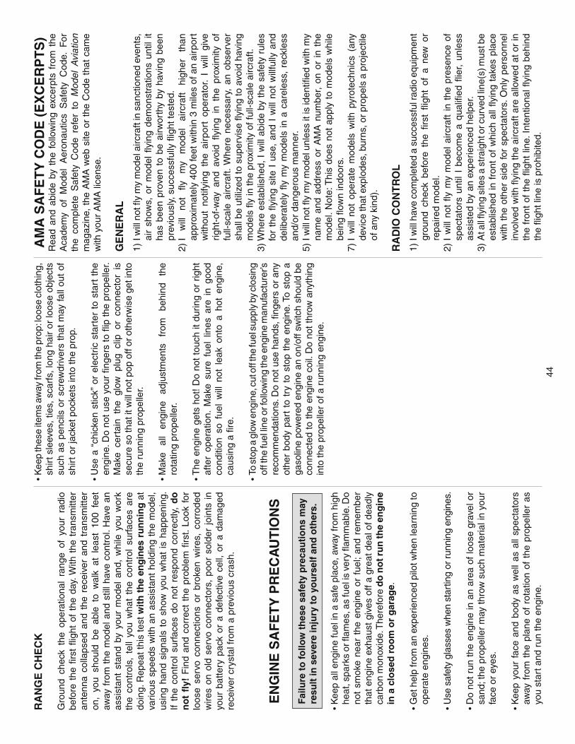
44
RA
NG
E C
HE
CK
Gro
und
chec
k th
e op
erat
iona
l ra
nge
of y
our
radi
o be
fore
the
fi r
st fl
ight
of
the
day.
With
the
tra
nsm
itter
an
tenn
a co
llaps
ed a
nd t
he r
ecei
ver
and
tran
smitt
er
on,
you
shou
ld b
e ab
le t
o w
alk
at l
east
100
fee
t aw
ay f
rom
the
mod
el a
nd s
till h
ave
cont
rol.
Hav
e an
as
sist
ant
stan
d by
you
r m
odel
and
, w
hile
you
wor
k th
e co
ntro
ls,
tell
you
wha
t th
e co
ntro
l su
rfac
es a
re
doin
g. R
epea
t thi
s te
st w
ith
th
e en
gin
es r
un
nin
g a
t va
rious
spe
eds
with
an
assi
stan
t ho
ldin
g th
e m
odel
, us
ing
hand
sig
nals
to
show
you
wha
t is
hap
peni
ng.
If th
e co
ntro
l su
rfac
es d
o no
t re
spon
d co
rrec
tly,
do
n
ot
fl y!
Fin
d an
d co
rrec
t th
e pr
oble
m fi
rst
. Lo
ok f
or
loos
e se
rvo
conn
ectio
ns o
r br
oken
wire
s, c
orro
ded
wire
s on
old
ser
vo c
onne
ctor
s, p
oor
sold
er j
oint
s in
yo
ur b
atte
ry p
ack
or a
def
ectiv
e ce
ll, o
r a
dam
aged
re
ceiv
er c
ryst
al fr
om a
pre
viou
s cr
ash.
EN
GIN
E S
AF
ET
Y P
RE
CA
UT
ION
S
Failu
re t
o f
ollo
w t
hes
e sa
fety
pre
cau
tio
ns
may
re
sult
in s
ever
e in
jury
to
yo
urs
elf
and
oth
ers.
• K
eep
all e
ngin
e fu
el in
a s
afe
plac
e, a
way
from
hig
h he
at, s
park
s or
fl am
es, a
s fu
el is
ver
y fl a
mm
able
. Do
not
smok
e ne
ar t
he e
ngin
e or
fue
l; an
d re
mem
ber
that
eng
ine
exha
ust g
ives
off
a gr
eat d
eal o
f dea
dly
carb
on m
onox
ide.
The
refo
re d
o n
ot r
un
the
eng
ine
in a
clo
sed
ro
om
or
gar
age.
• G
et h
elp
from
an
expe
rienc
ed p
ilot w
hen
lear
ning
to
oper
ate
engi
nes.
• U
se s
afet
y gl
asse
s w
hen
star
ting
or r
unni
ng e
ngin
es.
• D
o no
t ru
n th
e en
gine
in a
n ar
ea o
f lo
ose
grav
el o
r sa
nd; t
he p
rope
ller
may
thro
w s
uch
mat
eria
l in
your
fa
ce o
r ey
es.
• K
eep
your
fac
e an
d bo
dy a
s w
ell
as a
ll sp
ecta
tors
aw
ay f
rom
the
pla
ne o
f ro
tatio
n of
the
pro
pelle
r as
yo
u st
art a
nd r
un th
e en
gine
.
• K
eep
thes
e ite
ms
away
from
the
prop
: loo
se c
loth
ing,
sh
irt s
leev
es, t
ies,
sca
rfs,
long
hai
r or
loos
e ob
ject
s su
ch a
s pe
ncils
or
scre
wdr
iver
s th
at m
ay fa
ll ou
t of
sh
irt o
r ja
cket
poc
kets
into
the
prop
.
• U
se a
“ch
icke
n st
ick”
or
elec
tric
sta
rter
to
star
t th
e en
gine
. Do
not u
se y
our
fi nge
rs to
fl ip
the
prop
elle
r. M
ake
cert
ain
the
glow
plu
g cl
ip o
r co
nnec
tor
is
secu
re s
o th
at it
will
not
pop
off
or o
ther
wis
e ge
t int
o th
e ru
nnin
g pr
opel
ler.
• M
ake
all
engi
ne
adju
stm
ents
fr
om
behi
nd
the
rota
ting
prop
elle
r.
• T
he e
ngin
e ge
ts h
ot!
Do
not
touc
h it
durin
g or
rig
ht
afte
r op
erat
ion.
Mak
e su
re f
uel
lines
are
in
good
co
nditi
on s
o fu
el w
ill n
ot l
eak
onto
a h
ot e
ngin
e,
caus
ing
a fi r
e.
• To
sto
p a
glow
eng
ine,
cut
off
the
fuel
sup
ply
by c
losi
ng
off t
he fu
el li
ne o
r fol
low
ing
the
engi
ne m
anuf
actu
rer’s
re
com
men
datio
ns. D
o no
t use
han
ds, fi
nge
rs o
r an
y ot
her
body
par
t to
try
to
stop
the
eng
ine.
To
stop
a
gaso
line
pow
ered
eng
ine
an o
n/of
f sw
itch
shou
ld b
e co
nnec
ted
to th
e en
gine
coi
l. D
o no
t thr
ow a
nyth
ing
into
the
prop
elle
r of
a r
unni
ng e
ngin
e.
AM
A S
AF
ET
Y C
OD
E (
EX
CE
RP
TS
)R
ead
and
abid
e by
the
fol
low
ing
exce
rpts
fro
m t
he
Aca
dem
y of
Mod
el A
eron
autic
s S
afet
y C
ode.
For
th
e co
mpl
ete
Saf
ety
Cod
e re
fer
to M
odel
Avi
atio
n m
agaz
ine,
the
AM
A w
eb s
ite o
r th
e C
ode
that
cam
e w
ith y
our
AM
A li
cens
e.
GE
NE
RA
L
1) I
will
not
fl y
my
mod
el a
ircra
ft in
san
ctio
ned
even
ts,
air
show
s, o
r m
odel
fl y
ing
dem
onst
ratio
ns u
ntil
it ha
s be
en p
rove
n to
be
airw
orth
y by
hav
ing
been
pr
evio
usly
, suc
cess
fully
fl ig
ht te
sted
.2)
I w
ill
not
fl y
my
mod
el
airc
raft
high
er
than
ap
prox
imat
ely
400
feet
with
in 3
mile
s of
an
airp
ort
with
out
notif
ying
the
air
port
ope
rato
r. I
will
giv
e rig
ht-o
f-w
ay a
nd a
void
fl y
ing
in t
he p
roxi
mity
of
full-
scal
e ai
rcra
ft. W
here
nec
essa
ry,
an o
bser
ver
shal
l be
utili
zed
to s
uper
vise
fl yi
ng to
avo
id h
avin
g m
odel
s fl y
in th
e pr
oxim
ity o
f ful
l-sca
le a
ircra
ft.3)
Whe
re e
stab
lishe
d, I
will
abi
de b
y th
e sa
fety
rul
es
for
the
fl yin
g si
te I
use
, an
d I
will
not
will
fully
and
de
liber
atel
y fl y
my
mod
els
in a
car
eles
s, r
eckl
ess
and/
or d
ange
rous
man
ner.
5) I
will
not
fl y
my
mod
el u
nles
s it
is id
entifi
ed
with
my
nam
e an
d ad
dres
s or
AM
A n
umbe
r, on
or
in t
he
mod
el. N
ote:
Thi
s do
es n
ot a
pply
to
mod
els
whi
le
bein
g fl o
wn
indo
ors.
7) I
will
not
ope
rate
mod
els
with
pyr
otec
hnic
s (a
ny
devi
ce th
at e
xplo
des,
bur
ns, o
r pr
opel
s a
proj
ectil
e of
any
kin
d).
RA
DIO
CO
NT
RO
L
1) I
will
hav
e co
mpl
eted
a s
ucce
ssfu
l rad
io e
quip
men
t gr
ound
che
ck b
efor
e th
e fi r
st fl
ight
of
a ne
w o
r re
paire
d m
odel
.2)
I w
ill n
ot fl
y m
y m
odel
airc
raft
in t
he p
rese
nce
of
spec
tato
rs u
ntil
I be
com
e a
qual
ifi ed
fl ie
r, un
less
as
sist
ed b
y an
exp
erie
nced
hel
per.
3) A
t all
fl yin
g si
tes
a st
raig
ht o
r cur
ved
line(
s) m
ust b
e es
tabl
ishe
d in
fro
nt o
f w
hich
all
fl yin
g ta
kes
plac
e w
ith t
he o
ther
sid
e fo
r sp
ecta
tors
. Onl
y pe
rson
nel
invo
lved
with
fl yi
ng th
e ai
rcra
ft ar
e al
low
ed a
t or
in
the
fron
t of
the
fl ig
ht li
ne. I
nten
tiona
l fl y
ing
behi
nd
the
fl igh
t lin
e is
pro
hibi
ted.

45
4) I
will
ope
rate
my
mod
el u
sing
onl
y ra
dio
cont
rol
freq
uenc
ies
curr
ently
al
low
ed
by
the
Fed
eral
C
omm
unic
atio
ns C
omm
issi
on.
5) I
will
no
t kn
ow
ing
ly o
per
ate
my
mo
del
wit
hin
th
ree
mile
s o
f an
y p
re-e
xist
ing
fl
yin
g
site
ex
cep
t in
ac
cord
ance
w
ith
th
e fr
equ
ency
sh
arin
g a
gre
emen
t lis
ted
[in
the
com
plet
e A
MA
S
afet
y C
ode]
.9)
Und
er
no
circ
umst
ance
s m
ay
a pi
lot
or
othe
r pe
rson
touc
h a
pow
ered
mod
el in
fl ig
ht; n
or s
ho
uld
an
y p
art
of
the
mo
del
oth
er t
han
th
e la
nd
ing
g
ear,
inte
nti
on
ally
to
uch
th
e g
rou
nd
, ex
cep
t w
hile
lan
din
g. C
HE
CK
LIS
T
Dur
ing
the
last
fe
w
mom
ents
of
pr
epar
atio
n yo
ur
min
d m
ay
be
else
whe
re
antic
ipat
ing
the
exci
tem
ent
of t
he fi
rst
fl ig
ht. B
ecau
se o
f th
is,
you
may
be
mor
e lik
ely
to o
verlo
ok c
erta
in c
heck
s an
d pr
oced
ures
tha
t sh
ould
be
perf
orm
ed b
efor
e th
e m
odel
is
fl ow
n. T
o he
lp a
void
thi
s, a
che
ck l
ist
is
prov
ided
to
mak
e su
re t
hese
impo
rtan
t ar
eas
are
not o
verlo
oked
. Man
y ar
e co
vere
d in
the
inst
ruct
ion
man
ual,
so w
here
app
ropr
iate
, ref
er to
the
man
ual
for
com
plet
e in
stru
ctio
ns.
Be
sure
to
chec
k th
e ite
ms
off a
s th
ey a
re c
ompl
eted
.
❏ 1
. Mak
e su
re y
ou h
ave
chec
ked
the
C.G
. acc
ordi
ng
to th
e m
easu
rem
ents
and
pro
cedu
res
prov
ided
.❏
2. B
alan
ce y
our
mod
el la
tera
lly a
s ex
plai
ned.
❏ 3
. Be
cert
ain
the
batte
ry a
nd r
ecei
ver
are
secu
rely
m
ount
ed.
Sim
ply
stuf
fi ng
them
int
o pl
ace
with
fo
am r
ubbe
r is
not
suf
fi cie
nt.
❏ 4
. Ext
end
the
rece
iver
ant
enna
all
the
way
dow
n th
e an
tenn
a tu
be in
the
fuse
lage
.❏
5. U
se t
hrea
dloc
king
com
poun
d to
sec
ure
criti
cal
fast
ener
s su
ch a
s th
e se
t scr
ews
on th
e re
tract
able
la
ndin
g ge
ar s
trut
s an
d ax
les
or w
heel
col
lars
, sc
rew
-lock
pus
hrod
con
nect
ors,
etc
.❏
6. B
e ce
rtai
n th
e sc
rew
s ho
ldin
g th
e ho
rizon
tal
stab
ilize
r an
d th
e ve
rtic
al
stab
ilize
rs
have
be
en s
ecur
ely
tight
ened
with
thr
eadl
ocke
r on
th
e th
read
s.
❏ 7
. Add
a d
rop
of o
il to
the
axl
es s
o th
e w
heel
s w
ill
turn
free
ly.
❏ 8
. Mak
e su
re a
ll hi
nges
are
sec
urel
y gl
ued
in p
lace
.❏
9. R
einf
orce
hol
es f
or w
ood
scre
ws
with
thi
n C
A
whe
re
appr
opria
te
(ser
vo
mou
ntin
g sc
rew
s,
cano
py m
ount
ing
scre
ws,
etc
.).
❏ 10
. Con
fi rm
tha
t al
l con
trol
s op
erat
e in
the
cor
rect
di
rect
ion
and
the
thro
ws
are
set
up a
ccor
ding
to
the
man
ual.
❏ 11
. Mak
e su
re t
here
are
sili
cone
ret
aine
rs o
n al
lth
e cl
evis
es.
❏ 12
. Mak
e su
re a
ll se
rvo
arm
s ar
e se
cure
d to
the
se
rvos
with
the
scre
ws
that
cam
e w
ith th
em.
❏ 13
. Whe
re a
ppro
pria
te, s
ecur
e co
nnec
tions
bet
wee
n se
rvo
wire
s an
d Y-
conn
ecto
rs o
r ser
vo e
xten
sion
s,
and
the
conn
ectio
n be
twee
n yo
ur b
atte
ry p
ack
and
the
on/o
ff sw
itch
with
vin
yl ta
pe, h
eat s
hrin
k tu
bing
or s
peci
al c
lips
suita
ble
for t
hat p
urpo
se.
❏ 14
. Mak
e su
re a
ny s
ervo
ext
ensi
on w
ires
you
may
ha
ve u
sed
do n
ot in
terf
ere
with
oth
er s
yste
ms
(ser
vo a
rms,
pus
hrod
s, c
able
s, e
tc.)
.❏
15. M
ake
sure
the
fuel
line
s ar
e co
nnec
ted
and
are
not k
inke
d.❏
16. B
alan
ce th
e pr
opel
lers
(an
d sp
are
prop
elle
rs).
❏ 17
. Sec
urel
y tig
hten
the
prop
elle
r hu
bs. B
e ce
rtai
n to
use
thre
adlo
cker
on
the
thre
ads.
❏
18. P
lace
you
r na
me,
add
ress
, A
MA
num
ber
and
tele
phon
e nu
mbe
r on
or
insi
de y
our
mod
el.
❏ 19
. Cyc
le y
our
rece
iver
bat
tery
pac
k (if
nec
essa
ry)
and
mak
e su
re it
is fu
lly c
harg
ed.
❏ 20
. If
you
wis
h to
pho
togr
aph
your
mod
el,
do s
o be
fore
you
r fi r
st fl
ight
.❏
21. R
ange
che
ck y
our
radi
o w
hen
you
get
to t
he
fl yin
g fi e
ld.
FLY
ING
The
Top
Flit
e B
-25J
Mitc
hell
AR
F is
a g
reat
-fl yi
ng m
odel
th
at fl
ies
smoo
thly
and
pre
dict
ably
. The
B-2
5 do
es n
ot,
how
ever
, po
sses
s th
e se
lf-re
cove
ry
char
acte
ristic
s of
a p
rimar
y R
/C t
rain
er a
nd s
houl
d be
fl o
wn
only
by
expe
rienc
ed R
/C p
ilots
.
MO
UN
T T
HE
WIN
GS
Ass
umin
g th
e ou
ter
pane
ls
and
tail
have
be
en
mou
nted
to
the
mod
el a
t th
e w
ork
shop
and
you
’ve
tran
spor
ted
it in
this
con
fi gur
atio
n, c
onne
ct th
e ai
lero
n an
d fl a
p se
rvo
wire
s an
d m
ount
the
out
boar
d pa
nels
to
the
inbo
ard
pane
ls.
FU
EL
MIX
TU
RE
AD
JUS
TM
EN
TS
A fu
lly c
owle
d en
gine
may
run
at a
hig
her t
empe
ratu
re
than
an
un-c
owle
d en
gine
. F
or t
his
reas
on,
the
fuel
m
ixtu
re s
houl
d be
ric
hene
d sl
ight
ly s
o th
e en
gine
ru
ns a
t abo
ut 2
00 r
pm b
elow
pea
k sp
eed.
By
runn
ing
the
engi
ne s
light
ly r
ich,
you
will
hel
p pr
even
t de
ad-
stic
k la
ndin
gs c
ause
d by
ove
rhea
ting.
CA
UT
ION
(T
HIS
A
PP
LIE
S
TO
ALL
R
/C
AIR
PLA
NE
S):
If,
whi
le
fl yin
g,
you
notic
e an
al
arm
ing
or u
nusu
al s
ound
suc
h as
a lo
w-p
itche
d “b
uzz,
” th
is
may
in
dica
te
cont
rol
surfa
ce
fl utte
r. F
lutte
r oc
curs
whe
n a
cont
rol s
urfa
ce (
such
as
an
aile
ron
or e
leva
tor)
or
a fl y
ing
surfa
ce (
such
as
a w
ing
or s
tab)
rap
idly
vib
rate
s up
and
dow
n (t
hus
caus
ing
the
nois
e). I
n ex
trem
e ca
ses,
if n
ot d
etec
ted
imm
edia
tely
, fl u
tter
can
actu
ally
cau
se t
he c
ontr
ol
surfa
ce t
o de
tach
or
the
fl yin
g su
rface
to
fail,
thu
s ca
usin
g lo
ss o
f co
ntro
l fo
llow
ed b
y an
im
pend
ing
cras
h. T
he b
est t
hing
to d
o w
hen
fl utte
r is
det
ecte
d is
to
slow
the
mod
el i
mm
edia
tely
by
redu
cing
po
wer
, the
n la
nd a
s so
on a
s sa
fely
pos
sibl
e. Id
entif
y w
hich
sur
face
fl u
ttere
d (s
o th
e pr
oble
m m
ay b
e re
solv
ed)
by c
heck
ing
all
the
serv
o gr
omm
ets
for
dete
riora
tion
or s
igns
of
vibr
atio
n. M
ake
cert
ain
all
push
rod
linka
ges
are
secu
re a
nd f
ree
of p
lay.
If
it fl u
ttere
d on
ce,
unde
r si
mila
r ci
rcum
stan
ces
it w
ill
prob
ably
fl u
tter
agai
n un
less
the
pro
blem
is
fi xed
. S
ome
thin
gs w
hich
can
cau
se fl
utte
r are
; Exc
essi
ve
hing
e ga
p; N
ot m
ount
ing
cont
rol h
orns
sol
idly
; Poo
r fi t
of
clev
is p
in in
hor
n; S
ide-
play
of
wire
pus
hrod
s ca
used
by
la
rge
bend
s;
Exc
essi
ve
free
pl
ay
in
serv
o ge
ars;
Ins
ecur
e se
rvo
mou
ntin
g; a
nd o
ne o
f th
e m
ost p
reva
lent
cau
ses
of fl
utte
r; fl y
ing
an o
ver-
pow
ered
mod
el a
t exc
essi
ve s
peed
s.
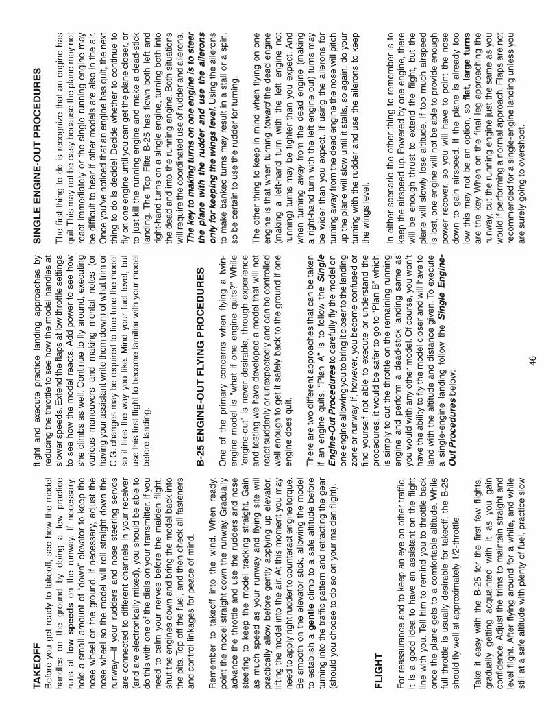
46
TAK
EO
FF
Bef
ore
you
get
read
y to
tak
eoff,
see
how
the
mod
el
hand
les
on
the
grou
nd
by
doin
g a
few
pr
actic
e ru
ns a
t lo
w s
pee
ds
on t
he r
unw
ay.
If ne
cess
ary,
ho
ld a
sm
all
amou
nt o
f “d
own”
ele
vato
r to
kee
p th
e no
se w
heel
on
the
grou
nd.
If ne
cess
ary,
adj
ust
the
nose
whe
el s
o th
e m
odel
will
rol
l st
raig
ht d
own
the
runw
ay—
if yo
ur r
udde
rs a
nd n
ose
stee
ring
serv
os
are
conn
ecte
d to
diff
eren
t ch
anne
ls i
n yo
ur r
ecei
ver
(and
are
ele
ctro
nica
lly m
ixed
), y
ou s
houl
d be
abl
e to
do
this
with
one
of t
he d
ials
on
your
tran
smitt
er. I
f you
ne
ed t
o ca
lm y
our
nerv
es b
efor
e th
e m
aide
n fl i
ght,
shut
the
engi
nes
dow
n an
d br
ing
the
mod
el b
ack
into
th
e pi
ts. T
op o
ff th
e fu
el, a
nd th
en c
heck
all
fast
ener
s an
d co
ntro
l lin
kage
s fo
r pe
ace
of m
ind.
Rem
embe
r to
tak
eoff
into
the
win
d. W
hen
read
y,
poin
t th
e m
odel
str
aigh
t do
wn
the
runw
ay. G
radu
ally
ad
vanc
e th
e th
rottl
e an
d us
e th
e ru
dder
s an
d no
se
stee
ring
to k
eep
the
mod
el t
rack
ing
stra
ight
. G
ain
as m
uch
spee
d as
you
r ru
nway
and
fl y
ing
site
will
pr
actic
ally
allo
w b
efor
e ge
ntly
app
lyin
g up
ele
vato
r, lif
ting
the
mod
el in
to th
e ai
r. A
t thi
s m
omen
t you
may
ne
ed to
app
ly ri
ght r
udde
r to
coun
tera
ct e
ngin
e to
rque
. B
e sm
ooth
on
the
elev
ator
stic
k, a
llow
ing
the
mod
el
to e
stab
lish
a g
entl
e cl
imb
to a
saf
e al
titud
e be
fore
tu
rnin
g in
to t
he t
raffi
c pa
ttern
and
ret
ract
ing
the
gear
(s
houl
d yo
u ch
oose
to d
o so
on
your
mai
den
fl igh
t).
FL
IGH
T
For
rea
ssur
ance
and
to
keep
an
eye
on o
ther
tra
ffi c,
it
is a
goo
d id
ea t
o ha
ve a
n as
sist
ant
on t
he fl
ight
lin
e w
ith y
ou. T
ell h
im t
o re
min
d yo
u to
thr
ottle
bac
k on
ce t
he p
lane
get
s to
a c
omfo
rtab
le a
ltitu
de. W
hile
fu
ll th
rottl
e is
usu
ally
des
irabl
e fo
r ta
keof
f, th
e B
-25
shou
ld fl
y w
ell a
t app
roxi
mat
ely
1/2-
thro
ttle.
Take
it
easy
with
the
B-2
5 fo
r th
e fi r
st f
ew fl
ight
s,
grad
ually
ge
tting
ac
quai
nted
w
ith
it as
yo
u ga
in
confi
den
ce. A
djus
t th
e tr
ims
to m
aint
ain
stra
ight
and
le
vel
fl igh
t. A
fter
fl yin
g ar
ound
for
a w
hile
, an
d w
hile
st
ill a
t a s
afe
altit
ude
with
ple
nty
of fu
el, p
ract
ice
slow
fl igh
t an
d ex
ecut
e pr
actic
e la
ndin
g ap
proa
ches
by
redu
cing
the
thro
ttle
to s
ee h
ow th
e m
odel
han
dles
at
slow
er s
peed
s. E
xten
d th
e fl a
ps a
t low
thro
ttle
setti
ngs
to s
ee h
ow t
he m
odel
rea
cts.
Add
pow
er t
o se
e ho
w
she
clim
bs a
s w
ell.
Con
tinue
to
fl y a
roun
d, e
xecu
ting
vario
us
man
euve
rs
and
mak
ing
men
tal
note
s (o
r ha
ving
you
r ass
ista
nt w
rite
them
dow
n) o
f wha
t trim
or
C.G
. cha
nges
may
be
requ
ired
to fi
ne tu
ne th
e m
odel
so
it
fl ies
the
way
you
lik
e. M
ind
your
fue
l le
vel,
but
use
this
fi rs
t fl ig
ht to
bec
ome
fam
iliar
with
you
r m
odel
be
fore
land
ing.
B-2
5 E
NG
INE
-OU
T F
LYIN
G P
RO
CE
DU
RE
S
One
of
the
prim
ary
conc
erns
whe
n fl y
ing
a tw
in-
engi
ne m
odel
is
"wha
t if
one
engi
ne q
uits
?" W
hile
“e
ngin
e-ou
t” is
nev
er d
esira
ble,
thr
ough
exp
erie
nce
and
test
ing
we
have
dev
elop
ed a
mod
el t
hat
will
not
re
act s
udde
nly
or u
nexp
ecte
dly
and
can
be c
ontr
olle
d w
ell e
noug
h to
get
it s
afel
y ba
ck to
the
grou
nd if
one
en
gine
doe
s qu
it.
The
re a
re tw
o di
ffere
nt a
ppro
ache
s th
at c
an b
e ta
ken
if an
eng
ine
quits
. “P
lan
A”
is t
o fo
llow
the
Sin
gle
E
ng
ine-
Ou
t Pro
ced
ure
s to
car
eful
ly fl
y th
e m
odel
on
one
engi
ne a
llow
ing
you
to b
ring
it cl
oser
to th
e la
ndin
g zo
ne o
r ru
nway
. If,
how
ever
, you
bec
ome
conf
used
or
fi nd
your
self
not
able
to
exec
ute
or u
nder
stan
d th
e pr
oced
ures
, it w
ould
be
safe
r to
go
to “
Pla
n B
” w
hich
is
sim
ply
to c
ut t
he t
hrot
tle o
n th
e re
mai
ning
run
ning
en
gine
and
per
form
a d
ead-
stic
k la
ndin
g sa
me
as
you
wou
ld w
ith a
ny o
ther
mod
el. O
f cou
rse,
you
won
’t ha
ve th
e ab
ility
to fl
y th
e m
odel
clo
ser a
nd w
ill h
ave
to
land
with
the
alti
tude
and
dis
tanc
e gi
ven.
To
exec
ute
a si
ngle
-eng
ine
land
ing
follo
w t
he S
ing
le E
ng
ine-
Ou
t P
roce
du
res
belo
w:
SIN
GL
E E
NG
INE
-OU
T P
RO
CE
DU
RE
S
The
fi rs
t th
ing
to d
o is
rec
ogni
ze t
hat
an e
ngin
e ha
s qu
it. T
his
may
not
be
easy
bec
ause
the
plan
e m
ay n
ot
reac
t im
med
iate
ly o
r th
e si
ngle
run
ning
eng
ine
may
be
diffi
cul
t to
hea
r if
othe
r m
odel
s ar
e al
so in
the
air.
O
nce
you’
ve n
otic
ed th
at a
n en
gine
has
qui
t, th
e ne
xt
thin
g to
do
is d
ecid
e! D
ecid
e w
heth
er t
o co
ntin
ue t
o fl y
on
one
engi
ne u
ntil
you
can
get t
he p
lane
clo
ser,
or
to ju
st k
ill t
he r
unni
ng e
ngin
e an
d m
ake
a de
ad-s
tick
land
ing.
The
Top
Flit
e B
-25
has
fl ow
n bo
th l
eft
and
right
-han
d tu
rns
on a
sin
gle
engi
ne,
turn
ing
both
into
th
e de
ad a
nd in
to th
e ru
nnin
g en
gine
. Bot
h si
tuat
ions
w
ill re
quire
the
coor
dina
ted
use
of ru
dder
and
aile
rons
. T
he
key
to m
akin
g tu
rns
on
on
e en
gin
e is
to s
teer
th
e p
lan
e w
ith
th
e ru
dder
an
d u
se t
he
aile
ron
s o
nly
for
keep
ing
the
win
gs
leve
l. U
sing
the
aile
rons
to
mak
e ba
nked
tur
ns m
ay r
esul
t in
a s
tall
or a
spi
n,
so b
e ce
rtai
n to
use
the
rudd
er fo
r tu
rnin
g.
The
oth
er t
hing
to
keep
in
min
d w
hen
fl yin
g on
one
en
gine
is t
hat
whe
n tu
rnin
g to
war
d th
e de
ad e
ngin
e (m
akin
g a
left-
hand
tur
n w
ith t
he l
eft
engi
ne n
ot
runn
ing)
tur
ns m
ay b
e tig
hter
tha
n yo
u ex
pect
. A
nd
whe
n tu
rnin
g aw
ay f
rom
the
dea
d en
gine
(m
akin
g a
right
-han
d tu
rn w
ith t
he le
ft en
gine
out
) tu
rns
may
be
wid
er t
han
you
expe
ct.
If us
ing
the
aile
rons
for
tu
rnin
g aw
ay fr
om th
e de
ad e
ngin
e th
e no
se w
ill p
itch
up th
e pl
ane
will
slo
w u
ntil
it st
alls
, so
agai
n, d
o yo
ur
turn
ing
with
the
rud
der
and
use
the
aile
rons
to
keep
th
e w
ings
leve
l.
In e
ither
sce
nario
the
oth
er t
hing
to
rem
embe
r is
to
keep
the
airs
peed
up.
Pow
ered
by
one
engi
ne,
ther
e w
ill b
e en
ough
thr
ust
to e
xten
d th
e fl i
ght,
but
the
plan
e w
ill s
low
ly l
ose
altit
ude.
If
too
muc
h ai
rspe
ed
is lo
st, o
ne e
ngin
e w
ill n
ot b
e ab
le to
pro
vide
eno
ugh
pow
er r
ecov
er,
so y
ou w
ill h
ave
to p
oint
the
nos
e do
wn
to g
ain
airs
peed
. If
the
plan
e is
alre
ady
too
low
thi
s m
ay n
ot b
e an
opt
ion,
so
fl at
, la
rge
turn
s ar
e th
e ke
y. W
hen
on t
he fi
nal
leg
app
roac
hing
the
ru
nway
, cu
t th
e ru
nnin
g en
gine
just
the
sam
e as
you
w
ould
if p
erfo
rmin
g a
norm
al a
ppro
ach.
Fla
ps a
re n
ot
reco
mm
ende
d fo
r a s
ingl
e-en
gine
land
ing
unle
ss y
ou
are
sure
ly g
oing
to o
vers
hoot
.
47
If no
t pr
ofi c
ient
w
ith
the
rudd
er
or
if an
xiou
s ab
out
beco
min
g co
nfus
ed
with
si
ngle
en
gine
-out
pr
oced
ures
, it
may
be
safe
r ju
st t
o cu
t th
e th
rottl
e an
d pe
rfor
m a
dea
d-st
ick
land
ing
the
sam
e as
you
w
ould
any
oth
er s
ingl
e-en
gine
pla
ne. O
f co
urse
, yo
u w
ill h
ave
to la
nd w
ith th
e al
titud
e an
d di
stan
ce g
iven
. A
gain
, do
not
ext
end
the
fl aps
on
a si
ngle
-eng
ine
or
engi
ne-o
ut l
andi
ng (
unle
ss y
ou a
re a
lread
y ov
er o
r ve
ry n
ear
the
runw
ay).
Her
e’s
a re
view
of
the
Sin
gle
En
gin
e-O
ut
Pro
ced
ure
s:
1. R
eco
gn
ize
that
an
engi
ne h
as q
uit.
2. D
ecid
e w
heth
er to
con
tinue
fl yi
ng o
n on
e en
gine
or
to c
ut th
e ot
her
engi
ne a
nd d
ead-
stic
k im
med
iate
ly.
3. R
emem
ber
—us
e th
e ru
dder
to d
o th
e tu
rnin
g an
d us
e th
e ai
lero
ns to
kee
p th
e w
ings
leve
l. Tu
rns
arou
nd
the
dead
eng
ine
will
be
tight
er a
nd t
urns
aw
ay f
rom
th
e de
ad e
ngin
e w
ill b
e w
ide.
4. M
ain
tain
you
r ai
rspe
ed.
LA
ND
ING
The
B-2
5 m
ay b
e la
nded
with
or
with
out
fl aps
. Fla
ps
incr
ease
lift
and
dra
g, s
o th
e pl
ane
may
be
land
ed
with
le
ss
grou
nd
spee
d,
thus
sh
orte
ning
ro
llout
af
ter
touc
hdow
n (n
ot a
s m
uch
of a
fac
tor
on g
rass
ru
nway
s).
To i
nitia
te a
lan
ding
app
roac
h, l
ower
the
th
rottl
e w
hile
on
the
dow
nwin
d le
g (p
aral
lel
with
the
ru
nway
, bu
t go
ing
the
oppo
site
dire
ctio
n).
If us
ing
fl aps
, al
low
the
mod
el t
o sl
ow,
then
ext
end
the
fl aps
. C
ontin
ue
to
lose
al
titud
e,
but
mai
ntai
n ai
rspe
ed
by k
eepi
ng t
he n
ose
dow
n as
you
tur
n on
to t
he
cros
swin
d le
g. M
ake
the
fi nal
turn
tow
ard
the
runw
ay
(into
the
win
d) k
eepi
ng t
he n
ose
dow
n to
mai
ntai
n ai
rspe
ed a
nd c
ontr
ol.
If la
ndin
g w
ith fl
aps
kee
p a
few
add
ition
al “
clic
ks”
of p
ower
so
the
mod
el d
oesn
’t sl
ow t
oo
muc
h. L
evel
the
atti
tude
whe
n th
e m
odel
re
ache
s th
e ru
nway
thr
esho
ld a
nd i
s ap
prox
imat
ely
ten
feet
[3 m
eter
s] a
bove
the
grou
nd, m
odul
atin
g th
e th
rottl
e as
nec
essa
ry t
o m
aint
ain
the
glid
e pa
th a
nd
airs
peed
. If
you
are
goin
g to
ove
rsho
ot t
he r
unw
ay,
smoo
thly
adv
ance
the
thr
ottle
(al
way
s re
ady
on t
he
right
rudd
er to
cou
nter
act t
orqu
e) a
nd re
trac
t the
fl ap
s w
hen
enou
gh a
irspe
ed is
gai
ned.
Clim
b ou
t to
mak
e an
othe
r at
tem
pt. W
hen
fi nal
ly r
eady
to
land
and
the
m
odel
is a
foot
or s
o of
f the
dec
k an
d yo
u ar
e re
ady
to
mak
e th
e la
ndin
g fl a
re, s
moo
thly
incr
ease
up
elev
ator
un
til t
he w
heel
s ge
ntly
tou
ch d
own.
Onc
e th
e m
odel
is
on
the
runw
ay a
nd h
as lo
st fl
ying
spe
ed, h
old
dow
n el
evat
or to
hol
d th
e no
se o
n th
e gr
ound
. No
te: I
f eve
r th
e oc
casi
on a
rises
whe
n a
dead
-stic
k la
ndin
g m
ust
be p
erfo
rmed
, do
not
ext
end
the
fl aps
unt
il ce
rtai
n
the
mod
el w
ill b
e ab
le t
o re
ach
the
land
ing
zone
(on
de
ad-s
tick
land
ings
it is
com
mon
to la
nd w
ith n
o fl a
ps
at a
ll). W
ithou
t eng
ine
pow
er, fl
aps
can
une
xpec
tedl
y re
duce
the
mod
el’s
ran
ge, t
hus
caus
ing
you
to c
ome
up s
hort
of t
he fi
eld.
One
fi n
al n
ote
abou
t fl y
ing
your
B-2
5 A
RF.
Hav
e a
goal
or
fl igh
t pl
an i
n m
ind
for
ever
y fl i
ght.
The
goa
l co
uld
be le
arni
ng a
new
man
euve
r, pe
rfec
ting
know
n m
aneu
vers
, or
lea
rnin
g ho
w t
he m
odel
beh
aves
in
cert
ain
cond
ition
s (s
uch
as o
n hi
gh o
r low
rate
s). T
his
is n
ot n
eces
saril
y to
impr
ove
your
ski
lls (
thou
gh it
is
neve
r a
bad
idea
!),
but
mor
e im
port
antly
so
you
do
not
surp
rise
your
self
by i
mp
uls
ivel
y at
tem
ptin
g a
man
euve
r w
ithou
t pl
anni
ng. E
very
man
euve
r sh
ould
be
del
iber
ate.
For
exa
mpl
e, if
per
form
ing
a lo
op, p
lan
it ou
t—ch
eck
your
alti
tude
, m
ind
the
win
d di
rect
ion
(ant
icip
atin
g ru
dder
cor
rect
ions
tha
t w
ill b
e re
quire
d to
mai
ntai
n he
adin
g),
rem
embe
r to
thr
ottle
bac
k on
th
e do
wn
side
, an
d m
ake
cert
ain
you
are
on t
he
desi
red
rate
s (h
igh/
low
rat
es).
A fl
ight
pla
n gr
eatly
re
duce
s th
e ch
ance
s of
cra
shin
g ju
st b
ecau
se o
f poo
r pl
anni
ng a
nd im
puls
ive
mov
es. R
emem
ber
to
th
ink!
Hav
e a
bal
l! B
ut
alw
ays
stay
in c
on
tro
l an
d fl
y in
a s
afe
man
ner
.
GO
OD
LU
CK
AN
D G
RE
AT
FLY
ING
!
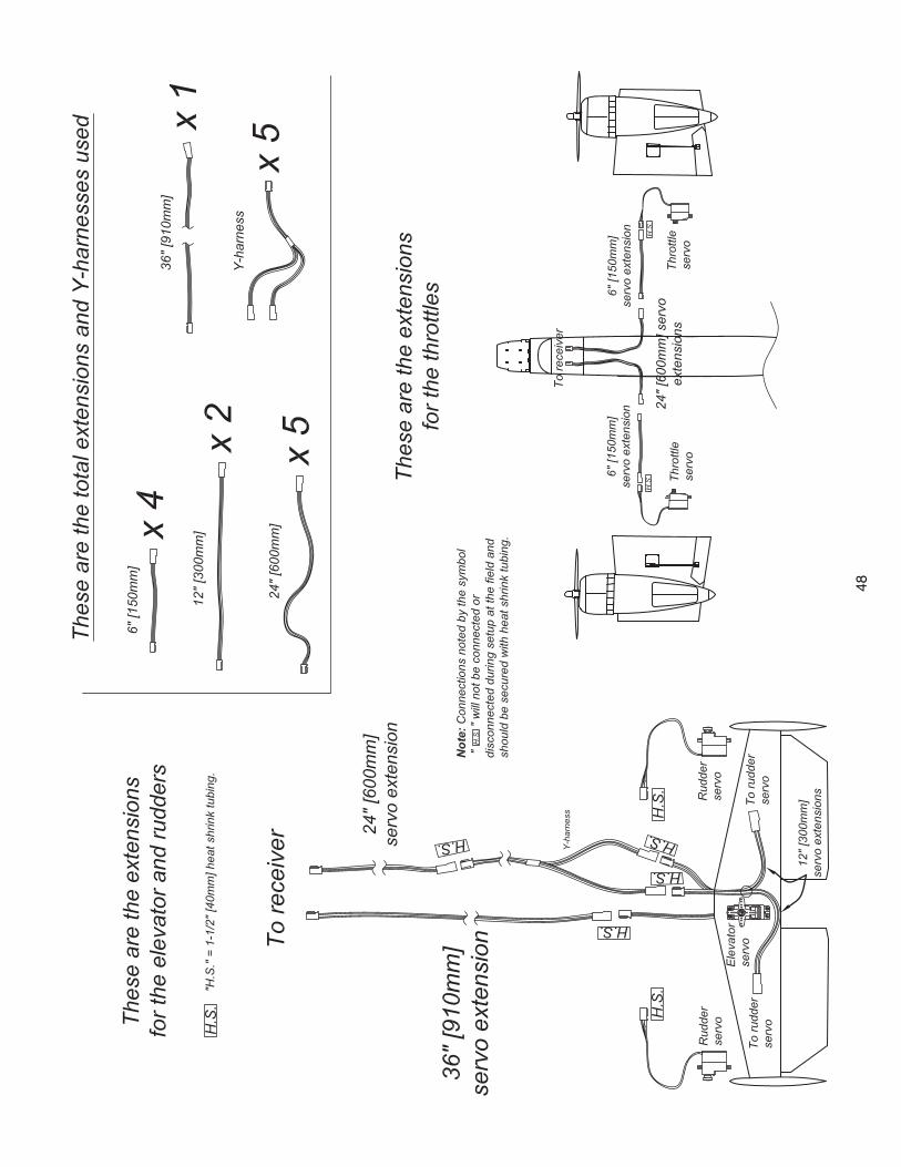
48
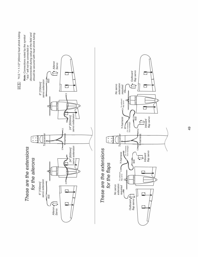
49
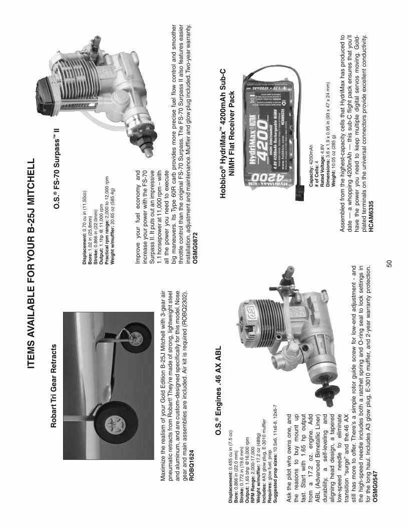
50
ITE
MS
AVA
ILA
BL
E F
OR
YO
UR
B-2
5J M
ITC
HE
LL
Impr
ove
your
fu
el
econ
omy
and
incr
ease
you
r po
wer
with
the
FS
-70
Sur
pass
II. I
t put
s ou
t an
impr
essi
ve
1.1
hors
epow
er a
t 11,
000
rpm
– w
ith
all
the
pow
er y
ou n
eed
to e
xecu
te
big
man
euve
rs.
Its T
ype
60R
car
b pr
ovid
es m
ore
prec
ise
fuel
flo
w c
ontr
ol a
nd s
moo
ther
th
rottl
e co
ntro
l tha
n th
e or
igin
al F
S-7
0 S
urpa
ss. T
he F
S-7
0 S
urpa
ss I
I al
so fe
atur
es e
asie
r in
stal
latio
n, a
djus
tmen
t and
mai
nten
ance
. Muf
fler a
nd g
low
plu
g in
clud
ed. T
wo-
year
war
rant
y.
OS
MG
0872
Dis
pla
cem
ent:
0.7
0 cu
in (
11.5
0cc)
Bo
re:
1.02
in (
25.8
mm
)S
tro
ke:
0.86
6 in
(22
.0m
m)
Ou
tpu
t: 1
.1hp
@ 1
1,00
0 rp
mP
ract
ical
rp
m r
ang
e: 2
,000
to 1
2,00
0 rp
mW
eig
ht
w/m
uff
ler:
20.
65 o
z (5
85.4
g)
O.S
.® F
S-7
0 S
urp
ass™
II
Ask
the
pilo
t w
ho o
wns
one
, an
d th
e re
ason
s to
bu
y m
ount
up
fa
st.
Sta
rt
with
1.
65
hp
outp
ut
from
a
17.2
oz
. en
gine
. A
dd
AB
L (A
dvan
ced
Bim
etal
lic L
iner
) du
rabi
lity,
a
self-
leve
ling
and
alig
ning
hea
d de
sign
, a
tape
red
low
-spe
ed
need
le
to
elim
inat
e tr
ansi
tion
“sur
ge”
and
the.
46 A
X
still
has
mor
e to
offe
r. T
here
's a
sim
ple
roto
r gu
ide
scre
w f
or l
ow-e
nd a
djus
tmen
t -
and
the
high
-spe
ed n
eedl
e in
clud
es b
oth
a ra
tche
t sp
ring
and
O-r
ing
seal
to
lock
set
tings
in
for
the
long
hau
l. In
clud
es A
3 gl
ow p
lug,
E-3
010
muf
fler,
and
2-ye
ar w
arra
nty
prot
ectio
n.
OS
MG
0547
Dis
pla
cem
ent:
0.4
55 c
u in
(7.
5 cc
)B
ore
: 0.
866
in (
22.0
mm
)S
tro
ke:
0.77
2 in
(19
.6 m
m)
Ou
tpu
t: 1
.65
bhp
@16
,000
rpm
RP
M R
ang
e: 2
,000
-17,
000
Wei
gh
t w
/mu
ffle
r: 1
7.2
oz (
489g
)In
clu
des
: #A
3 gl
ow p
lug,
E-3
010
muf
fler
Req
uir
es:
glow
fuel
, pro
pS
ug
ges
ted
pro
p s
izes
: 10.
5x6,
11x
6-8,
12x
6-7
O.S
.® E
ng
ines
.46
AX
AB
L
Max
imiz
e th
e re
alis
m o
f you
r G
old
Edi
tion
B-2
5J M
itche
ll w
ith 3
-gea
r ai
r pn
eum
atic
retr
acts
from
Rob
art!
The
y’re
mad
e of
str
ong,
ligh
twei
ght s
teel
an
d al
umin
um, a
nd a
re c
usto
m-d
esig
ned
spec
ifi ca
lly fo
r thi
s m
odel
. Nos
e ge
ar a
nd m
ain
asse
mbl
ies
are
incl
uded
. Air
kit i
s re
quire
d (R
OB
Q23
02).
RO
BQ
1624
Ass
embl
ed f
rom
the
hig
hest
-cap
acity
cel
ls t
hat
Hyd
riMax
has
pro
duce
d to
da
te —
a w
hopp
ing
4200
mA
h —
thi
s su
b-C
fl ig
ht p
ack
ensu
res
that
you
’ll
have
the
pow
er y
ou n
eed
to k
eep
mul
tiple
dig
ital
serv
os m
ovin
g. G
old-
plat
ed te
rmin
als
on th
e un
iver
sal c
onne
ctor
s pr
ovid
e ex
celle
nt c
ondu
ctiv
ity.
HC
AM
6335
Ro
bar
t Tri
Gea
r R
etra
cts
Ho
bb
ico
® H
ydri
Max
™ 4
200m
Ah
Su
b-C
N
iMH
Fla
t R
ecei
ver
Pac
k
Cap
acit
y: 4
200m
Ah
# o
f C
ells
: 4R
ated
Vo
ltag
e: 4
.8V
Dim
ensi
on
s: 3
.6 x
1.9
x 0
.95
in (
93 x
47
x 24
mm
)W
eig
ht:
10.
05 o
z (2
85 g
)

Bot
tom
of p
lane
Bot
tom
of p
lane
Bot
tom
of p
lane
Rig
ht
engi
ne m
ount
ing
tem
plat
efo
r O
.S. .
70 fo
ur-s
trok
eL
eft
engi
ne m
ount
ing
tem
plat
efo
r O
.S. .
70 fo
ur-s
trok
e
Lef
t en
gine
mou
ntin
g te
mpl
ate
for
O.S
. tw
o-st
roke
Rig
ht
engi
ne m
ount
ing
tem
plat
efo
r O
.S. t
wo-
stro
ke
Bot
tom
of p
lane
Cut
on
dotte
d lin
e
Cut
on
dotte
d lin
e
LE
FT
RIG
HT
RIG
HT
LE
FT
51