Embed Size (px)
Citation preview
WARRANTY.....Top Flite Models guarantees this kit to be free of defects in both material and workmanship at the date of purchase. This warranty does not cover any component parts damaged by use or modification. In no case shall Top Flite‘s liability exceed the original cost of the purchased kit. Further, Top Flite reserves the right to change or modify this warranty without notice. In that Top Flite has no control over the final assembly or material used for final assembly, no liability shall be assumed nor accepted for any damage resulting from the use by the user of the final user-assembled product. By the act of using the user-assembled product the user accepts all resulting liability. If the buyer is not prepared to accept the liability associated with the use of this product, the buyer is advised to immediately return this kit in new and unused condition to the place of purchase.
Top Flite Models, Champaign, Il Phone: (217)398-8970, Ext. 5 [email protected]
CRSGP05 V1.1
READ THROUGH THIS INSTRUCTION BOOK FIRST. IT CONTAINS IMPORTANT INSTRUCTIONS AND WARNINGS CONCERNING THE ASSEMBLY AND USE OF THIS MODEL.
© 2010 Hobbico®, Inc.
USAMADE IN
™
- 2 -
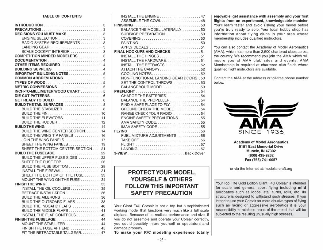
TABLE OF CONTENTS
INTRODUCTION . . . . . . . . . . . . . . . . . . . . . . . . . . . . . 3PRECAUTIONS . . . . . . . . . . . . . . . . . . . . . . . . . . . . . . 3DECISIONS YOU MUST MAKE . . . . . . . . . . . . . . . . . . 3 ENGINE SELECTION . . . . . . . . . . . . . . . . . . . . . . 3 RADIO SYSTEM REQUIREMENTS . . . . . . . . . . . 3 LANDING GEAR . . . . . . . . . . . . . . . . . . . . . . . . . . 3 SCALE COCKPIT INTERIOR . . . . . . . . . . . . . . . . 3COMPETITION MINDED MODELERS . . . . . . . . . . . . 3DOCUMENTATION . . . . . . . . . . . . . . . . . . . . . . . . . . . 4OTHER ITEMS REQUIRED . . . . . . . . . . . . . . . . . . . . . 4BUILDING SUPPLIES . . . . . . . . . . . . . . . . . . . . . . . . . 4IMPORTANT BUILDING NOTES . . . . . . . . . . . . . . . . . 5COMMON ABBREVIATIONS . . . . . . . . . . . . . . . . . . . 5TYPES OF WOOD . . . . . . . . . . . . . . . . . . . . . . . . . . . . 5METRIC CONVERSIONS . . . . . . . . . . . . . . . . . . . . . . 5INCH-TO-MILLIMETER WOOD CHART . . . . . . . . . . . 5DIE-CUT PATTERNS . . . . . . . . . . . . . . . . . . . . . . . . . . 6GET READY TO BUILD . . . . . . . . . . . . . . . . . . . . . . . . 8BUILD THE TAIL SURFACES . . . . . . . . . . . . . . . . . . . 8 BUILD THE STABILIZER. . . . . . . . . . . . . . . . . . . . 8 BUILD THE FIN . . . . . . . . . . . . . . . . . . . . . . . . . . 10 BUILD THE ELEVATORS . . . . . . . . . . . . . . . . . . 11 BUILD THE RUDDER . . . . . . . . . . . . . . . . . . . . . 12BUILD THE WING . . . . . . . . . . . . . . . . . . . . . . . . . . . 14 BUILD THE WING CENTER SECTION. . . . . . . . 14 BUILD THE WING TIP PANELS . . . . . . . . . . . . . 16 JOIN THE WING PANELS . . . . . . . . . . . . . . . . . . 17 SHEET THE WING PANELS . . . . . . . . . . . . . . . . 19 SHEET THE BOTTOM CENTER SECTION . . . . 21BUILD THE FUSELAGE . . . . . . . . . . . . . . . . . . . . . . 22 BUILD THE UPPER FUSE SIDES . . . . . . . . . . . 22 SHEET THE FUSE TOP . . . . . . . . . . . . . . . . . . . 26 BUILD THE FUSE BOTTOM . . . . . . . . . . . . . . . . 28 INSTALL THE FIREWALL . . . . . . . . . . . . . . . . . . 31 SHEET THE BOTTOM OF THE FUSE . . . . . . . . 33 MOUNT THE WING ON THE FUSE . . . . . . . . . . 34FINISH THE WING . . . . . . . . . . . . . . . . . . . . . . . . . . . 35 INSTALL THE OIL COOLERS . . . . . . . . . . . . . . . 35 RETRACT INSTALLATION . . . . . . . . . . . . . . . . . 36 BUILD THE AILERONS . . . . . . . . . . . . . . . . . . . . 36 BUILD THE OUTBOARD FLAPS . . . . . . . . . . . . 38 BUILD THE INBOARD FLAPS . . . . . . . . . . . . . . 40 BUILD THE MIDDLE FLAPS . . . . . . . . . . . . . . . . 41 INSTALL THE FLAP CONTROLS . . . . . . . . . . . . 42FINISH THE FUSELAGE . . . . . . . . . . . . . . . . . . . . . . 44 MOUNT THE STABILIZER . . . . . . . . . . . . . . . . . 44 FINISH THE FUSE AFT END . . . . . . . . . . . . . . . 45 FIT THE RETRACTABLE TAILGEAR. . . . . . . . . . 47
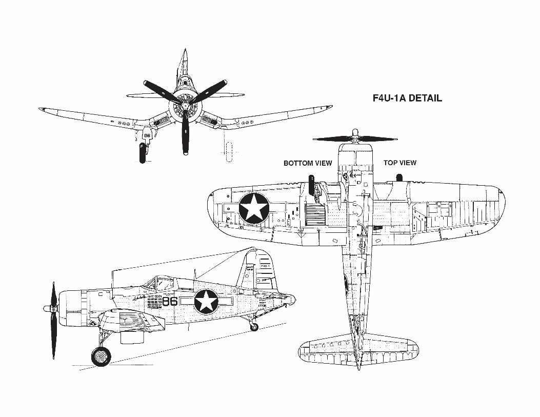
INSTALL THE ENGINE . . . . . . . . . . . . . . . . . . . . 47 ASSEMBLE THE COWL . . . . . . . . . . . . . . . . . . . 48FINISHING . . . . . . . . . . . . . . . . . . . . . . . . . . . . . . . . . 50 BALANCE THE MODEL LATERALLY . . . . . . . . . 50 SURFACE PREPARATION . . . . . . . . . . . . . . . . . 50 COVERING . . . . . . . . . . . . . . . . . . . . . . . . . . . . . 50 PAINTING . . . . . . . . . . . . . . . . . . . . . . . . . . . . . . 50 APPLY DECALS . . . . . . . . . . . . . . . . . . . . . . . . . 51FINAL HOOKUPS AND CHECKS. . . . . . . . . . . . . . . 51 INSTALL THE HINGES . . . . . . . . . . . . . . . . . . . . 51 INSTALL THE HARDWARE. . . . . . . . . . . . . . . . . 51 INSTALL THE RETRACTS . . . . . . . . . . . . . . . . . 52 ATTACH THE CANOPY . . . . . . . . . . . . . . . . . . . . 52 COOLING NOTES. . . . . . . . . . . . . . . . . . . . . . . . 52 NON-FUNCTIONAL LANDING GEAR DOORS . 53 SET THE CONTROL THROWS. . . . . . . . . . . . . . 53 BALANCE YOUR MODEL . . . . . . . . . . . . . . . . . . 53PREFLIGHT . . . . . . . . . . . . . . . . . . . . . . . . . . . . . . . . 54 CHARGE THE BATTERIES. . . . . . . . . . . . . . . . . 54 BALANCE THE PROPELLER . . . . . . . . . . . . . . . 54 FIND A SAFE PLACE TO FLY . . . . . . . . . . . . . . . 54 GROUND CHECK THE MODEL . . . . . . . . . . . . . 54 RANGE CHECK YOUR RADIO . . . . . . . . . . . . . . 54 ENGINE SAFETY PRECAUTIONS . . . . . . . . . . . 55 AMA SAFETY CODE. . . . . . . . . . . . . . . . . . . . . . 55 IMAA SAFETY CODE . . . . . . . . . . . . . . . . . . . . . 55FLYING. . . . . . . . . . . . . . . . . . . . . . . . . . . . . . . . . . . . 56 FUEL MIXTURE ADJUSTMENTS. . . . . . . . . . . . 56 TAKE OFF . . . . . . . . . . . . . . . . . . . . . . . . . . . . . . 56 FLIGHT . . . . . . . . . . . . . . . . . . . . . . . . . . . . . . . . 57 LANDING. . . . . . . . . . . . . . . . . . . . . . . . . . . . . . . 573-VIEW . . . . . . . . . . . . . . . . . . . . . . . . . . . . Back Cover
PROTECT YOUR MODEL, YOURSELF & OTHERS
FOLLOW THIS IMPORTANT SAFETY PRECAUTION
Your Giant F4U Corsair is not a toy, but a sophisticated working model that functions very much like a full scale airplane. Because of its realistic performance and size, if you do not assemble and operate your Corsair correctly, you could possibly injure yourself or spectators and damage property.To make your R/C modeling experience totally
enjoyable, get assistance with assembly and your first flights from an experienced, knowledgeable modeler. You’ll learn faster and avoid risking your model before you’re truly ready to solo. Your local hobby shop has information about flying clubs in your area whose membership includes qualified instructors.
You can also contact the Academy of Model Aeronautics (AMA), which has more than 2,500 chartered clubs across the country. We recommend you join the AMA which will insure you at AMA club sites and events. AMA Membership is required at chartered club fields where qualified flight instructors are available.
Contact the AMA at the address or toll-free phone number below.
Academy of Model Aeronautics5151 East Memorial Drive
Muncie, IN 47302(800) 435-9262
Fax (765) 741-0057
or via the Internet at: modelaircraft.org
Your Top Flite Gold Edition Giant F4U Corsair is intended for scale and general sport flying including mild aerobatics such as loops, stall turns, rolls, etc. Its structure is designed to withstand such stresses. If you intend to use your Corsair for more abusive types of flying such as racing or aggressive aerobatics it is your responsibility to reinforce areas of the model that will be subjected to the resulting unusually high stresses.
- 3 -
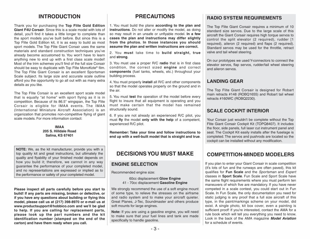
INTRODUCTION
Thank you for purchasing the Top Flite Gold Edition Giant F4U Corsair. Since this is a scale model with lots of detail, you’ll find it takes a little longer to complete than the sport models you’ve built before. But since this is a Top Flite Gold Edition kit, it is as easy to build as most sport models. The Top Flite Giant Corsair uses the same materials and standard construction techniques you’ve already become accustomed to. You won’t have to learn anything new to end up with a first class scale model! Most of the trim schemes you’ll find of the full size Corsair should be easy to duplicate with Top Flite MonoKote® film. The Top Flite Giant Corsair is an excellent Sportsman Scale subject. Its large size and accurate scale outline afford you the opportunity to go all out with as many extra details as you like.
The Top Flite Corsair is an excellent sport scale model that is equally “at home” with sport flying as it is in competition. Because of its 86.5" wingspan, the Top Flite Corsair is el igible for IMAA events. The IMAA (International Miniature Aircraft Association) is an organization that promotes non-competitive flying of giant scale models. For more information contact:
IMAA205 S. Hilldale Road
Salina, KS 67401
NOTE: We, as the kit manufacturer, provide you with a top quality kit and great instructions, but ultimately the quality and flyability of your finished model depends on how you build it; therefore, we cannot in any way guarantee the performance of your completed model, and no representations are expressed or implied as to the performance or safety of your completed model.
Please inspect all parts carefully before you start to build! If any parts are missing, broken or defective, or if you have any questions about building or flying this model, please call us at (217) 398-8970 or e-mail us at [email protected] and we’ll be glad to help. If you are calling for replacement parts, please look up the part numbers and the kit identification number (stamped on the end of the carton) and have them ready when you call.
PRECAUTIONS
1. You must build the plane according to the plan and instructions. Do not alter or modify the model, as doing so may result in an unsafe or unflyable model. In a few cases the plan and instructions may differ slightly from the photos. In those instances you should assume the plan and written instructions are correct.
2. You must take t ime to build straight, true and strong.
3. You must use a proper R/C radio that is in first class condition, the correct sized engine and correct components (fuel tanks, wheels, etc.) throughout your building process.
4. You must properly install all R/C and other components so that the model operates properly on the ground and in the air.
5. You must test the operation of the model before every flight to insure that all equipment is operating and you must make cer tain that the model has remained structurally sound.
6. If you are not already an experienced R/C pilot, you must fly the model only with the help of a competent, experienced R/C pilot.
Remember: Take your time and follow instructions to end up with a well-built model that is straight and true.
DECISIONS YOU MUST MAKE
ENGINE SELECTION
Recommended engine size:
60cc displacement Glow Engine41 - 70cc displacement Gasoline Engine
We strongly recommend the use of a soft engine mount of some type, to relieve the stresses on the airframe and radio system and to make your aircraft quieter. Great Planes, J-Tec, Soundmaster and others produce soft mounts for large engines.
Note: If you are using a gasoline engine, you will need to make sure that your fuel lines and tank are made specifically to handle gasoline.
RADIO SYSTEM REQUIREMENTS
The Top Flite Giant Corsair requires a minimum of 10 standard size servos. Due to the large scale of this aircraft the Giant Corsair requires high torque servos to control the split elevator (2 required), rudder [1 required), aileron (2 required) and flaps (2 required). Standard servos may be used for the throttle, retract valve and tail wheel steering.
On our prototypes we used Y-connectors to connect the elevator servos, flap servos, rudder/tail wheel steering and aileron servos.
LANDING GEAR
The Top Flite Giant Corsair is designed for Robart main retracts #148 (ROBQ1655) and Robart tail wheel retracts #160WC (ROBQ2230).
SCALE COCKPIT INTERIOR
Your Corsair just wouldn’t be complete without the Top Flite Giant Corsair Cockpit Kit (TOPQ8407). It includes the floor, side panels, full laser cut instrument panel and seat. The Cockpit Kit easily installs after the fuselage is completed. The servos and pushrods are located so the cockpit can be installed without any modification.
COMPETITION-MINDED MODELERS
If you plan to enter your Giant Corsair in scale competition (it’s lots of fun and the runways are often paved), this kit qualifies for Fun Scale and the Sportsman and Expert classes in Sport Scale. Fun Scale and Sport Scale have the same flight requirements where you must perform ten maneuvers of which five are mandatory. If you have never competed in a scale contest, you could start out in Fun Scale. In Fun Scale, the only documentation you need for static judging is any proof that a full size aircraft of this type, in the paint/markings scheme on your model, did exist. A single photo, kit box cover, even a painting is sufficient proof! If you’re interested, contact the AMA for a rule book which will tell you everything you need to know. Look in the back of the AMA magazine Model Aviation for a schedule of events.
- 4 -
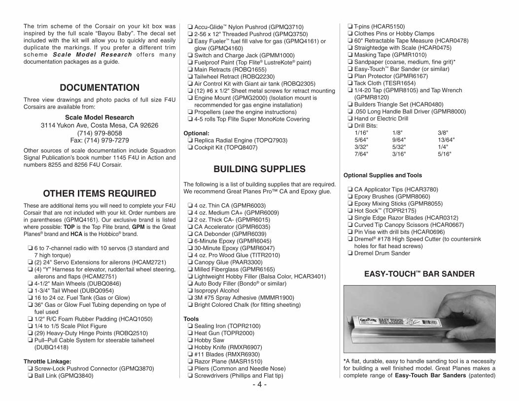
The trim scheme of the Corsair on your kit box was inspired by the full scale “Bayou Baby”. The decal set included with the kit will allow you to quickly and easily duplicate the markings. If you prefer a different trim scheme Scale Model Research o f fers many documentation packages as a guide.
DOCUMENTATIONThree view drawings and photo packs of full size F4U Corsairs are available from:
Scale Model Research3114 Yukon Ave, Costa Mesa, CA 92626
(714) 979-8058Fax: (714) 979-7279
Other sources of scale documentation include Squadron Signal Publication’s book number 1145 F4U in Action and numbers 8255 and 8256 F4U Corsair.
OTHER ITEMS REQUIREDThese are additional items you will need to complete your F4U Corsair that are not included with your kit. Order numbers are in parentheses (GPMQ4161). Our exclusive brand is listed where possible: TOP is the Top Flite brand, GPM is the Great Planes® brand and HCA is the Hobbico® brand.
❏ 6 to 7-channel radio with 10 servos (3 standard and 7 high torque)
❏ (2) 24" Servo Extensions for ailerons (HCAM2721) ❏ (4) “Y” Harness for elevator, rudder/tail wheel steering,
ailerons and flaps (HCAM2751) ❏ 4-1/2" Main Wheels (DUBQ0846) ❏ 1-3/4" Tail Wheel (DUBQ0954) ❏ 16 to 24 oz. Fuel Tank (Gas or Glow) ❏ 36" Gas or Glow Fuel Tubing depending on type of
fuel used ❏ 1/2" R/C Foam Rubber Padding (HCAQ1050) ❏ 1/4 to 1/5 Scale Pilot Figure ❏ (29) Heavy-Duty Hinge Points (ROBQ2510) ❏ Pull–Pull Cable System for steerable tailwheel
(DUBQ1418)
Throttle Linkage: ❏ Screw-Lock Pushrod Connector (GPMQ3870) ❏ Ball Link (GPMQ3840)
❏ Accu-Glide™ Nylon Pushrod (GPMQ3710) ❏ 2-56 x 12" Threaded Pushrod (GPMQ3750) ❏ Easy Fueler™ fuel fill valve for gas (GPMQ4161) or
glow (GPMQ4160) ❏ Switch and Charge Jack (GPMM1000) ❏ Fuelproof Paint (Top Flite® LustreKote® paint) ❏ Main Retracts (ROBQ1655) ❏ Tailwheel Retract (ROBQ2230) ❏ Air Control Kit with Giant air tank (ROBQ2305) ❏ (12) #6 x 1/2" Sheet metal screws for retract mounting ❏ Engine Mount (GPMG2000) (Isolation mount is
recommended for gas engine installation) ❏ Propellers (see the engine instructions) ❏ 4-5 rolls Top Flite Super MonoKote Covering
Optional: ❏ Replica Radial Engine (TOPQ7903) ❏ Cockpit Kit (TOPQ8407)
BUILDING SUPPLIES
The following is a list of building supplies that are required. We recommend Great Planes Pro™ CA and Epoxy glue.
❏ 4 oz. Thin CA (GPMR6003) ❏ 4 oz. Medium CA+ (GPMR6009) ❏ 2 oz. Thick CA- (GPMR6015) ❏ CA Accelerator (GPMR6035) ❏ CA Debonder (GPMR6039) ❏ 6-Minute Epoxy (GPMR6045) ❏ 30-Minute Epoxy (GPMR6047) ❏ 4 oz. Pro Wood Glue (TITR2010) ❏ Canopy Glue (PAAR3300) ❏ Milled Fiberglass (GPMR6165) ❏ Lightweight Hobby Filler (Balsa Color, HCAR3401) ❏ Auto Body Filler (Bondo® or similar) ❏ Isopropyl Alcohol ❏ 3M #75 Spray Adhesive (MMMR1900) ❏ Bright Colored Chalk (for fitting sheeting)
Tools ❏ Sealing Iron (TOPR2100) ❏ Heat Gun (TOPR2000) ❏ Hobby Saw ❏ Hobby Knife (RMXR6907) ❏ #11 Blades (RMXR6930) ❏ Razor Plane (MASR1510) ❏ Pliers (Common and Needle Nose) ❏ Screwdrivers (Phillips and Flat tip)
❏ T-pins (HCAR5150) ❏ Clothes Pins or Hobby Clamps ❏ 60" Retractable Tape Measure (HCAR0478) ❏ Straightedge with Scale (HCAR0475) ❏ Masking Tape (GPMR1010) ❏ Sandpaper (coarse, medium, fine grit)* ❏ Easy-Touch™ Bar Sander (or similar) ❏ Plan Protector (GPMR6167) ❏ Tack Cloth (TESR1654) ❏ 1/4-20 Tap (GPMR8105) and Tap Wrench
(GPMR8120) ❏ Builders Triangle Set (HCAR0480) ❏ .050 Long Handle Ball Driver (GPMR8000) ❏ Hand or Electric Drill ❏ Drill Bits: 1/16" 1/8" 3/8" 5/64" 9/64" 13/64" 3/32" 5/32" 1/4" 7/64" 3/16" 5/16"
Optional Supplies and Tools
❏ CA Applicator Tips (HCAR3780) ❏ Epoxy Brushes (GPMR8060) ❏ Epoxy Mixing Sticks (GPMR8055) ❏ Hot Sock™ (TOPR2175) ❏ Single Edge Razor Blades (HCAR0312) ❏ Curved Tip Canopy Scissors (HCAR0667) ❏ Pin Vise with drill bits (HCAR0696) ❏ Dremel® #178 High Speed Cutter (to countersink
holes for flat head screws) ❏ Dremel Drum Sander
EASY-TOUCH™ BAR SANDER
*A flat, durable, easy to handle sanding tool is a necessity for building a well finished model. Great Planes makes a complete range of Easy-Touch Bar Sanders (patented)
- 5 -
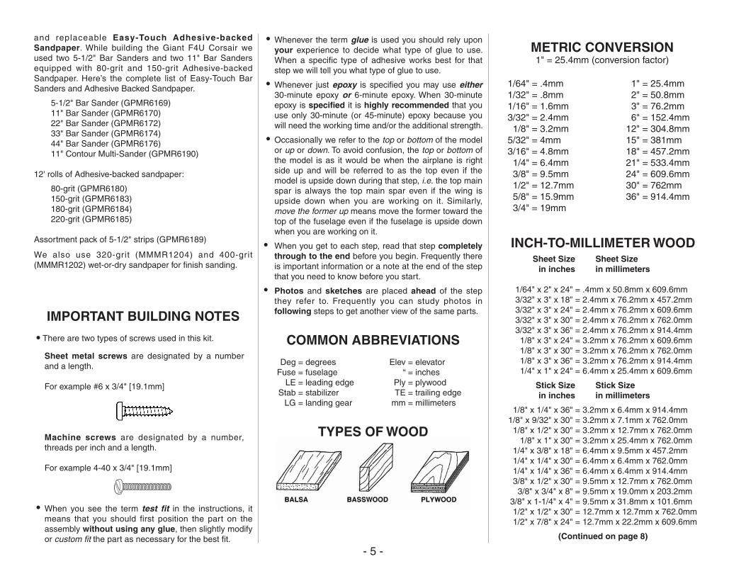
and replaceable Easy-Touch Adhesive-backed Sandpaper. While building the Giant F4U Corsair we used two 5-1/2" Bar Sanders and two 11" Bar Sanders equipped with 80-grit and 150-grit Adhesive-backed Sandpaper. Here’s the complete list of Easy-Touch Bar Sanders and Adhesive Backed Sandpaper.
5-1/2" Bar Sander (GPMR6169)11" Bar Sander (GPMR6170)22" Bar Sander (GPMR6172)33" Bar Sander (GPMR6174)44" Bar Sander (GPMR6176)11" Contour Multi-Sander (GPMR6190)
12' rolls of Adhesive-backed sandpaper:
80-grit (GPMR6180)150-grit (GPMR6183)180-grit (GPMR6184)220-grit (GPMR6185)
Assortment pack of 5-1/2" strips (GPMR6189)
We also use 320-grit (MMMR1204) and 400-grit (MMMR1202) wet-or-dry sandpaper for finish sanding.
IMPORTANT BUILDING NOTES
• There are two types of screws used in this kit.
Sheet metal screws are designated by a number and a length.
For example #6 x 3/4" [19.1mm]
Machine screws are designated by a number, threads per inch and a length.
For example 4-40 x 3/4" [19.1mm]
• When you see the term test fit in the instructions, it means that you should first position the part on the assembly without using any glue, then slightly modify or custom fit the part as necessary for the best fit.
• Whenever the term glue is used you should rely upon your experience to decide what type of glue to use. When a specific type of adhesive works best for that step we will tell you what type of glue to use.
• Whenever just epoxy is specified you may use either 30-minute epoxy or 6-minute epoxy. When 30-minute epoxy is specified it is highly recommended that you use only 30-minute (or 45-minute) epoxy because you will need the working time and/or the additional strength.
• Occasionally we refer to the top or bottom of the model or up or down. To avoid confusion, the top or bottom of the model is as it would be when the airplane is right side up and will be referred to as the top even if the model is upside down during that step, i.e. the top main spar is always the top main spar even if the wing is upside down when you are working on it. Similarly, move the former up means move the former toward the top of the fuselage even if the fuselage is upside down when you are working on it.
• When you get to each step, read that step completely through to the end before you begin. Frequently there is important information or a note at the end of the step that you need to know before you start.
• Photos and sketches are placed ahead of the step they refer to. Frequently you can study photos in following steps to get another view of the same parts.
COMMON ABBREVIATIONS
Deg = degrees Elev = elevator Fuse = fuselage “ = inches LE = leading edge Ply = plywood Stab = stabilizer TE = trailing edge LG = landing gear mm = millimeters
TYPES OF WOOD
METRIC CONVERSION1" = 25.4mm (conversion factor)
1/64" = .4mm 1/32" = .8mm 1/16" = 1.6mm 3/32" = 2.4mm 1/8" = 3.2mm 5/32" = 4mm 3/16" = 4.8mm 1/4" = 6.4mm 3/8" = 9.5mm 1/2" = 12.7mm 5/8" = 15.9mm 3/4" = 19mm
1" = 25.4mm 2" = 50.8mm 3" = 76.2mm 6" = 152.4mm 12" = 304.8mm 15" = 381mm 18" = 457.2mm 21" = 533.4mm 24" = 609.6mm 30" = 762mm 36" = 914.4mm
INCH-TO-MILLIMETER WOOD Sheet Size Sheet Size in inches in millimeters
1/64" x 2" x 24" = .4mm x 50.8mm x 609.6mm 3/32" x 3" x 18" = 2.4mm x 76.2mm x 457.2mm 3/32" x 3" x 24" = 2.4mm x 76.2mm x 609.6mm 3/32" x 3" x 30" = 2.4mm x 76.2mm x 762.0mm 3/32" x 3" x 36" = 2.4mm x 76.2mm x 914.4mm 1/8" x 3" x 24" = 3.2mm x 76.2mm x 609.6mm 1/8" x 3" x 30" = 3.2mm x 76.2mm x 762.0mm 1/8" x 3" x 36" = 3.2mm x 76.2mm x 914.4mm 1/4" x 1" x 24" = 6.4mm x 25.4mm x 609.6mm
Stick Size Stick Size in inches in millimeters
1/8" x 1/4" x 36" = 3.2mm x 6.4mm x 914.4mm 1/8" x 9/32" x 30" = 3.2mm x 7.1mm x 762.0mm 1/8" x 1/2" x 30" = 3.2mm x 12.7mm x 762.0mm 1/8" x 1" x 30" = 3.2mm x 25.4mm x 762.0mm 1/4" x 3/8" x 18" = 6.4mm x 9.5mm x 457.2mm 1/4" x 1/4" x 30" = 6.4mm x 6.4mm x 762.0mm 1/4" x 1/4" x 36" = 6.4mm x 6.4mm x 914.4mm 3/8" x 1/2" x 30" = 9.5mm x 12.7mm x 762.0mm 3/8" x 3/4" x 8" = 9.5mm x 19.0mm x 203.2mm 3/8" x 1-1/4" x 4" = 9.5mm x 31.8mm x 101.6mm 1/2" x 1/2" x 30" = 12.7mm x 12.7mm x 762.0mm 1/2" x 7/8" x 24" = 12.7mm x 22.2mm x 609.6mm
(Continued on page 8)
- 6 -
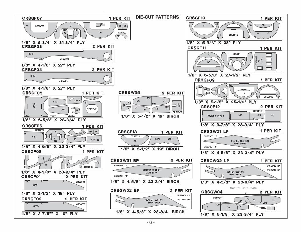
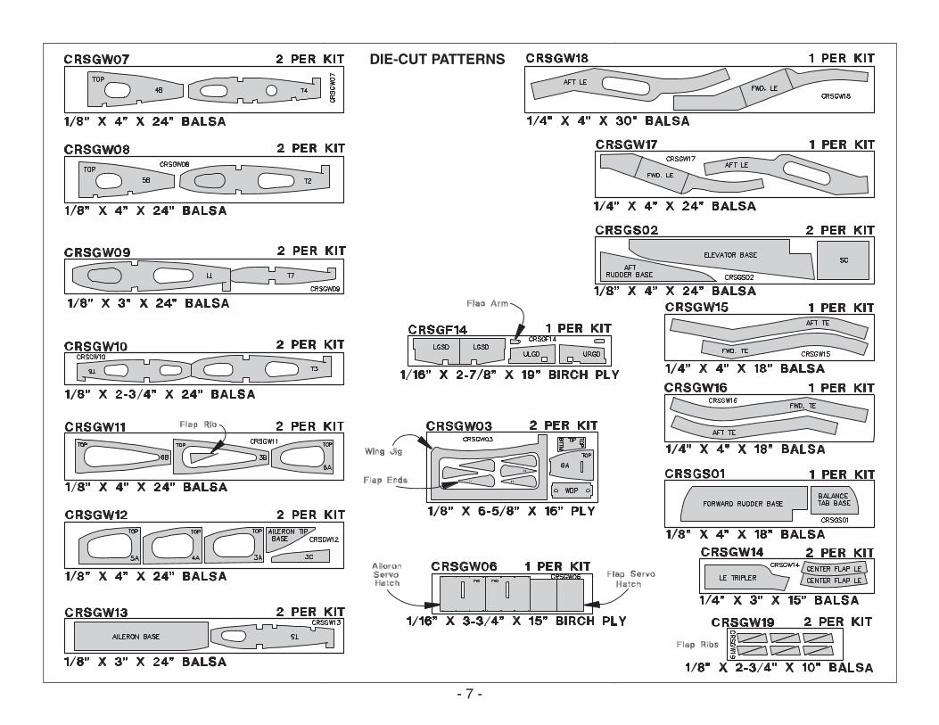
DIE-CUT PATTERNS
- 7 -
DIE-CUT PATTERNS
- 8 -
(Continued from page 5.)
1/2" x 15/16" x 18" = 12.7mm x 23.8mm x 457.2mm 1/2" x 1" x 3" = 12.7mm x 25.4mm x 76.2mm 1/2" x 1-1/4" x 30" = 12.7mm x 31.8mm x 762.0mm 5/8" x 3/4" x 6" = 15.9mm x 19.0mm x 152.4mm 11/16" x 11/16" x 18" = 17.5mm x 17.5mm x 457.2mm
Block Size Block Size in inches in millimeters
5/16" x 3/4" x 7/8" = 7.9mm x 19.0mm x 22.2mm 3/8" x 2" x 6" = 9.5mm x 50.8mm x 152.4mm 1/2" x 3" x 12" = 12.7mm x 76.2mm x 304.8mm 9/16" x 2" x 12" = 14.3mm x 50.8mm x 304.8mm 9/16" x 2-1/2" x 24" = 14.3mm x 63.5mm x 609.6mm 3/4" x 3/4" x 1" = 19.0mm x 19.0mm x 25.4mm 7/8" x 1-1/4" x 9-1/2" = 22.2mm x 31.8mm x 241.3mm 1-1/4" x 1-1/2" x 8" = 31.8mm x 38.1mm x 200.0mm 1-1/4" x 2" x 2-3/4" = 31.8mm x 50.8mm x 69.9mm
GET READY TO BUILD
1. Unroll the plan sheets. Re-roll the plans inside out to make them lie flat. Wax paper or Great Planes Plan Protector placed over the plan will prevent glue from sticking to the plan.
2. Remove all parts from the box. As you do, determine the name of each part by comparing it with the plans and the parts list included with this kit. Using a pencil or ballpoint pen, lightly write the part name or size on each piece to avoid confusion later. Use the die-cut patterns shown on pages 6 & 7 to identify the die-cut parts and mark them before removing them from the sheet. Save all leftovers. If any of the die-cut parts are difficult to remove, do not force them! Instead, cut around the parts. Use your Easy-Touch Bar Sander or sanding block to lightly sand the edges to remove any die-cutting irregularities.
3. As you identify and mark the parts, separate them into groups, such as fuse (fuselage), wing, fin, stab (stabilizer) and hardware. Zipper-top food storage bags are handy to store parts in as you sort, identify and separate them into subassemblies.
BUILD THE TAIL SURFACES
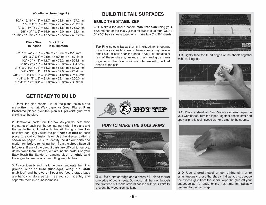
BUILD THE STABILIZER❏ 1. Make a top and a bottom stabilizer skin using your own method or the Hot Tip that follows to glue four 3/32" x 3" x 36" balsa sheets together to make two 6" x 36" sheets.
Top Flite selects balsa that is intended for sheeting, though occasionally a few of these sheets may have a small nick or split near the ends. If your kit contains a few of these sheets, arrange them and glue them together so the defects will not interfere with the final shape of the skin.
HOW TO MAKE THE STAB SKINS
❏ A. Use a straightedge and a sharp #11 blade to true one edge of both sheets. Do not cut all the way through the first time but make several passes with your knife to prevent the wood from splitting.
❏ B. Tightly tape the trued edges of the sheets together with masking tape.
❏ C. Place a sheet of Plan Protector or wax paper on your workbench. Turn the taped-together sheets over and apply aliphatic resin (wood workers glue) to the seams.
❏ D. Use a credit card or something similar to simultaneously press the sheets flat as you squeegee the excess glue from the seam. Wipe the glue off your squeegee so it’s ready for the next time. Immediately proceed to the next step.
- 9 -
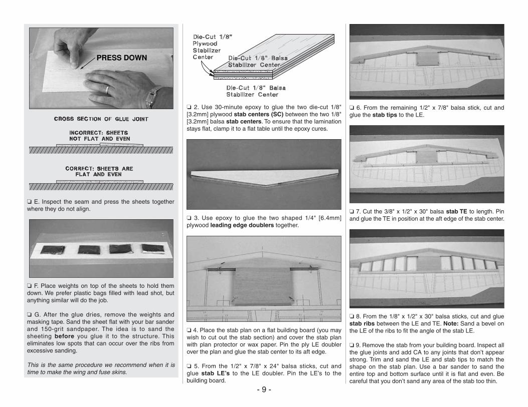
❏ E. Inspect the seam and press the sheets together where they do not align.
❏ F. Place weights on top of the sheets to hold them down. We prefer plastic bags filled with lead shot, but anything similar will do the job.
❏ G. After the glue dries, remove the weights and masking tape. Sand the sheet flat with your bar sander and 150-grit sandpaper. The idea is to sand the sheeting before you glue it to the structure. This eliminates low spots that can occur over the ribs from excessive sanding.
This is the same procedure we recommend when it is time to make the wing and fuse skins.
❏ 2. Use 30-minute epoxy to glue the two die-cut 1/8" [3.2mm] plywood stab centers (SC) between the two 1/8" [3.2mm] balsa stab centers. To ensure that the lamination stays flat, clamp it to a flat table until the epoxy cures.
❏ 3. Use epoxy to glue the two shaped 1/4" [6.4mm] plywood leading edge doublers together.
❏ 4. Place the stab plan on a flat building board (you may wish to cut out the stab section) and cover the stab plan with plan protector or wax paper. Pin the ply LE doubler over the plan and glue the stab center to its aft edge.
❏ 5. From the 1/2" x 7/8" x 24" balsa sticks, cut andglue stab LE’s to the LE doubler. Pin the LE’s to the building board.
❏ 6. From the remaining 1/2" x 7/8" balsa stick, cut and glue the stab tips to the LE.
❏ 7. Cut the 3/8" x 1/2" x 30" balsa stab TE to length. Pin and glue the TE in position at the aft edge of the stab center.
❏ 8. From the 1/8" x 1/2" x 30" balsa sticks, cut and glue stab ribs between the LE and TE. Note: Sand a bevel on the LE of the ribs to fit the angle of the stab LE.
❏ 9. Remove the stab from your building board. Inspect all the glue joints and add CA to any joints that don’t appear strong. Trim and sand the LE and stab tips to match the shape on the stab plan. Use a bar sander to sand the entire top and bottom surface until it is flat and even. Be careful that you don’t sand any area of the stab too thin.
- 10 -
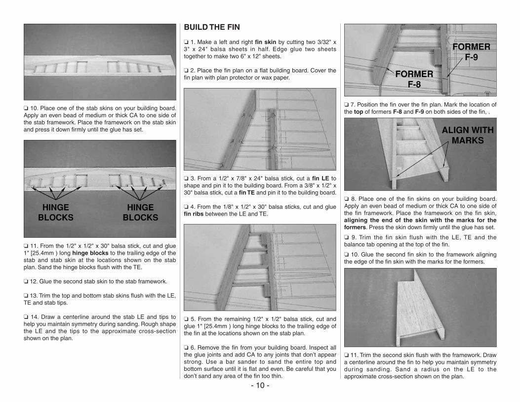
❏ 10. Place one of the stab skins on your building board. Apply an even bead of medium or thick CA to one side of the stab framework. Place the framework on the stab skin and press it down firmly until the glue has set.
❏ 11. From the 1/2" x 1/2" x 30" balsa stick, cut and glue 1" [25.4mm ) long hinge blocks to the trailing edge of the stab and stab skin at the locations shown on the stab plan. Sand the hinge blocks flush with the TE.
❏ 12. Glue the second stab skin to the stab framework.
❏ 13. Trim the top and bottom stab skins flush with the LE, TE and stab tips.
❏ 14. Draw a centerline around the stab LE and tips to help you maintain symmetry during sanding. Rough shape the LE and the tips to the approximate cross-section shown on the plan.
BUILD THE FIN
❏ 1. Make a left and right fin skin by cutting two 3/32" x 3" x 24" balsa sheets in half. Edge glue two sheets together to make two 6" x 12" sheets.
❏ 2. Place the fin plan on a flat building board. Cover the fin plan with plan protector or wax paper.
❏ 3. From a 1/2" x 7/8" x 24" balsa stick, cut a fin LE to shape and pin it to the building board. From a 3/8" x 1/2" x 30" balsa stick, cut a fin TE and pin it to the building board.
❏ 4. From the 1/8" x 1/2" x 30" balsa sticks, cut and glue fin ribs between the LE and TE.
❏ 5. From the remaining 1/2" x 1/2" balsa stick, cut and glue 1" [25.4mm ) long hinge blocks to the trailing edge of the fin at the locations shown on the stab plan.
❏ 6. Remove the fin from your building board. Inspect all the glue joints and add CA to any joints that don’t appear strong. Use a bar sander to sand the entire top and bottom surface until it is flat and even. Be careful that you don’t sand any area of the fin too thin.
❏ 7. Position the fin over the fin plan. Mark the location of the top of formers F-8 and F-9 on both sides of the fin, .
❏ 8. Place one of the fin skins on your building board. Apply an even bead of medium or thick CA to one side of the fin framework. Place the framework on the fin skin, aligning the end of the skin with the marks for the formers. Press the skin down firmly until the glue has set.
❏ 9. Trim the fin skin flush with the LE, TE and the balance tab opening at the top of the fin.
❏ 10. Glue the second fin skin to the framework aligning the edge of the fin skin with the marks for the formers.
❏ 11. Trim the second skin flush with the framework. Draw a centerline around the fin to help you maintain symmetry during sanding. Sand a radius on the LE to the approximate cross-section shown on the plan.
- 11 -
BUILD THE ELEVATORS
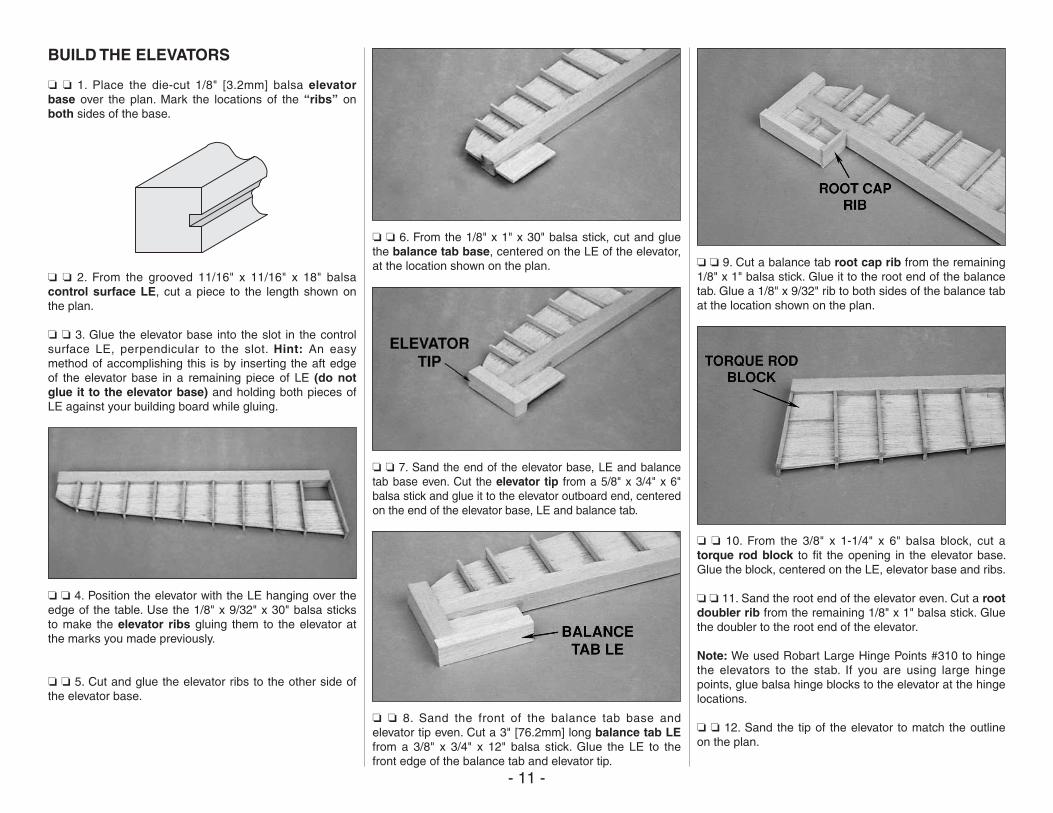
❏ ❏ 1. Place the die-cut 1/8" [3.2mm] balsa elevator base over the plan. Mark the locations of the “ribs” on both sides of the base.
❏ ❏ 2. From the grooved 11/16" x 11/16" x 18" balsa control surface LE, cut a piece to the length shown on the plan.
❏ ❏ 3. Glue the elevator base into the slot in the control surface LE, perpendicular to the slot. Hint: An easy method of accomplishing this is by inserting the aft edge of the elevator base in a remaining piece of LE (do not glue it to the elevator base) and holding both pieces of LE against your building board while gluing.
❏ ❏ 4. Position the elevator with the LE hanging over the edge of the table. Use the 1/8" x 9/32" x 30" balsa sticks to make the elevator ribs gluing them to the elevator at the marks you made previously.
❏ ❏ 5. Cut and glue the elevator ribs to the other side of the elevator base.
❏ ❏ 6. From the 1/8" x 1" x 30" balsa stick, cut and glue the balance tab base, centered on the LE of the elevator, at the location shown on the plan.
❏ ❏ 7. Sand the end of the elevator base, LE and balance tab base even. Cut the elevator tip from a 5/8" x 3/4" x 6" balsa stick and glue it to the elevator outboard end, centered on the end of the elevator base, LE and balance tab.
❏ ❏ 8. Sand the front of the balance tab base and elevator tip even. Cut a 3" [76.2mm] long balance tab LE from a 3/8" x 3/4" x 12" balsa stick. Glue the LE to the front edge of the balance tab and elevator tip.
❏ ❏ 9. Cut a balance tab root cap rib from the remaining 1/8" x 1" balsa stick. Glue it to the root end of the balance tab. Glue a 1/8" x 9/32" rib to both sides of the balance tab at the location shown on the plan.
❏ ❏ 10. From the 3/8" x 1-1/4" x 6" balsa block, cut a torque rod block to fit the opening in the elevator base. Glue the block, centered on the LE, elevator base and ribs.
❏ ❏ 11. Sand the root end of the elevator even. Cut a root doubler rib from the remaining 1/8" x 1" balsa stick. Glue the doubler to the root end of the elevator.
Note: We used Robart Large Hinge Points #310 to hinge the elevators to the stab. If you are using large hinge points, glue balsa hinge blocks to the elevator at the hinge locations.
❏ ❏ 12. Sand the tip of the elevator to match the outline on the plan.
- 12 -
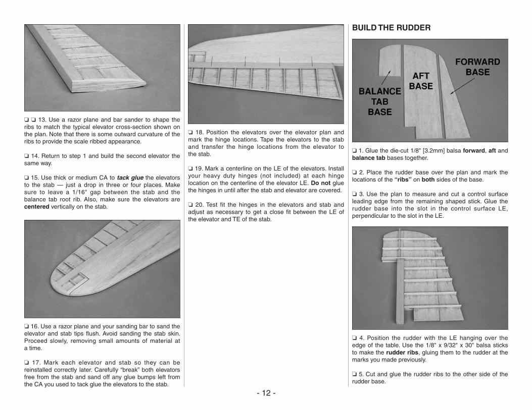
❏ ❏ 13. Use a razor plane and bar sander to shape the ribs to match the typical elevator cross-section shown on the plan. Note that there is some outward curvature of the ribs to provide the scale ribbed appearance.
❏ 14. Return to step 1 and build the second elevator the same way.
❏ 15. Use thick or medium CA to tack glue the elevators to the stab — just a drop in three or four places. Make sure to leave a 1/16" gap between the stab and the balance tab root rib. Also, make sure the elevators are centered vertically on the stab.
❏ 16. Use a razor plane and your sanding bar to sand the elevator and stab tips flush. Avoid sanding the stab skin. Proceed slowly, removing small amounts of material at a time.
❏ 17. Mark each elevator and stab so they can be reinstalled correctly later. Carefully “break” both elevators free from the stab and sand off any glue bumps left from the CA you used to tack glue the elevators to the stab.
❏ 18. Position the elevators over the elevator plan and mark the hinge locations. Tape the elevators to the stab and transfer the hinge locations from the elevator to the stab.
❏ 19. Mark a centerline on the LE of the elevators. Install your heavy duty hinges (not included) at each hinge location on the centerline of the elevator LE. Do not glue the hinges in until after the stab and elevator are covered.
❏ 20. Test fit the hinges in the elevators and stab and adjust as necessary to get a close fit between the LE of the elevator and TE of the stab.
BUILD THE RUDDER
❏ 1. Glue the die-cut 1/8" [3.2mm] balsa forward, aft and balance tab bases together.
❏ 2. Place the rudder base over the plan and mark the locations of the “ribs” on both sides of the base.
❏ 3. Use the plan to measure and cut a control surface leading edge from the remaining shaped stick. Glue the rudder base into the slot in the control surface LE, perpendicular to the slot in the LE.
❏ 4. Position the rudder with the LE hanging over the edge of the table. Use the 1/8" x 9/32" x 30" balsa sticks to make the rudder ribs, gluing them to the rudder at the marks you made previously.
❏ 5. Cut and glue the rudder ribs to the other side of the rudder base.
- 13 -
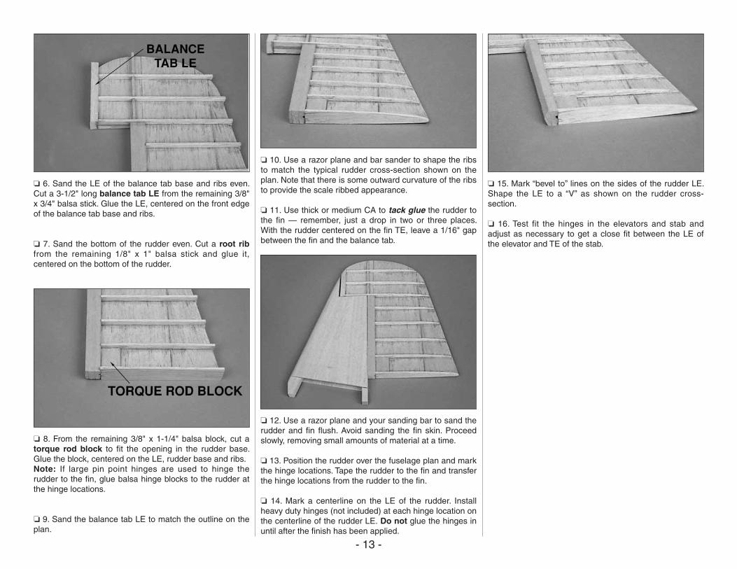
❏ 6. Sand the LE of the balance tab base and ribs even. Cut a 3-1/2" long balance tab LE from the remaining 3/8" x 3/4" balsa stick. Glue the LE, centered on the front edge of the balance tab base and ribs.
❏ 7. Sand the bottom of the rudder even. Cut a root rib from the remaining 1/8" x 1" balsa stick and glue it, centered on the bottom of the rudder.
❏ 8. From the remaining 3/8" x 1-1/4" balsa block, cut a torque rod block to fit the opening in the rudder base. Glue the block, centered on the LE, rudder base and ribs.Note: If large pin point hinges are used to hinge the rudder to the fin, glue balsa hinge blocks to the rudder at the hinge locations.
❏ 9. Sand the balance tab LE to match the outline on the plan.
❏ 10. Use a razor plane and bar sander to shape the ribs to match the typical rudder cross-section shown on the plan. Note that there is some outward curvature of the ribs to provide the scale ribbed appearance.
❏ 11. Use thick or medium CA to tack glue the rudder to the fin — remember, just a drop in two or three places. With the rudder centered on the fin TE, leave a 1/16" gap between the fin and the balance tab.
❏ 12. Use a razor plane and your sanding bar to sand the rudder and fin flush. Avoid sanding the fin skin. Proceed slowly, removing small amounts of material at a time.
❏ 13. Position the rudder over the fuselage plan and mark the hinge locations. Tape the rudder to the fin and transfer the hinge locations from the rudder to the fin.
❏ 14. Mark a centerline on the LE of the rudder. Install heavy duty hinges (not included) at each hinge location on the centerline of the rudder LE. Do not glue the hinges in until after the finish has been applied.
❏ 15. Mark “bevel to” lines on the sides of the rudder LE. Shape the LE to a “V” as shown on the rudder cross-section.
❏ 16. Test fit the hinges in the elevators and stab and adjust as necessary to get a close fit between the LE of the elevator and TE of the stab.
- 14 -
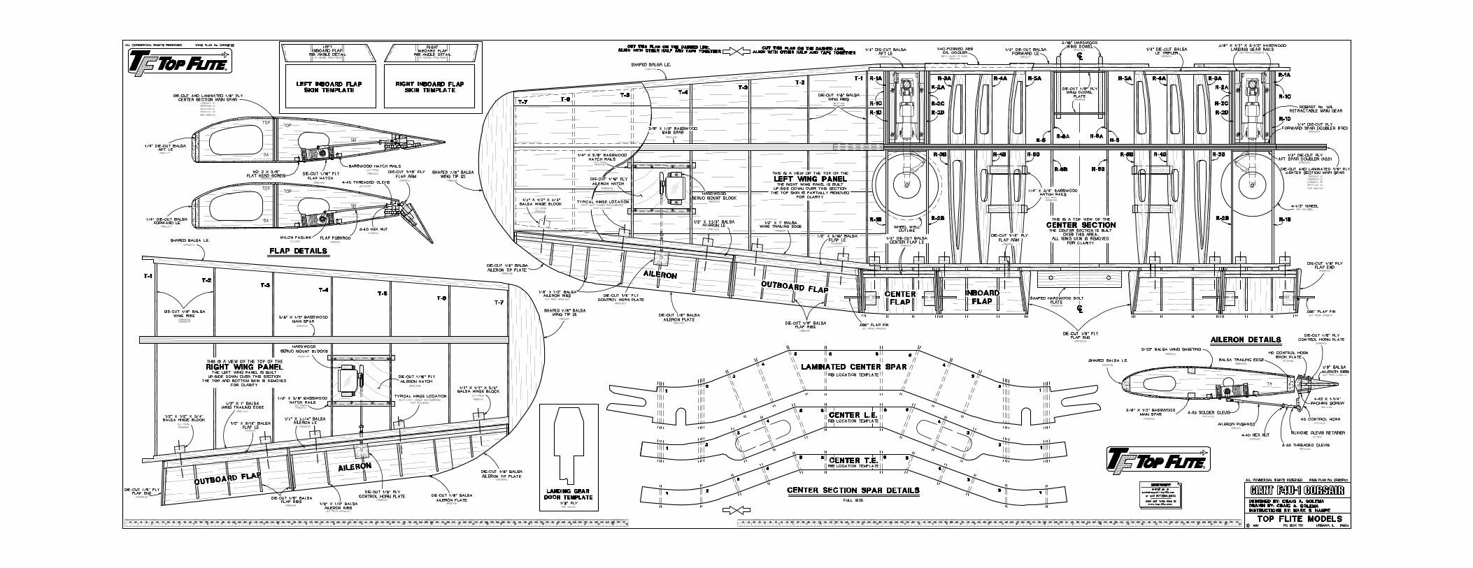
BUILD THE WING
BUILD THE WING CENTER SECTION
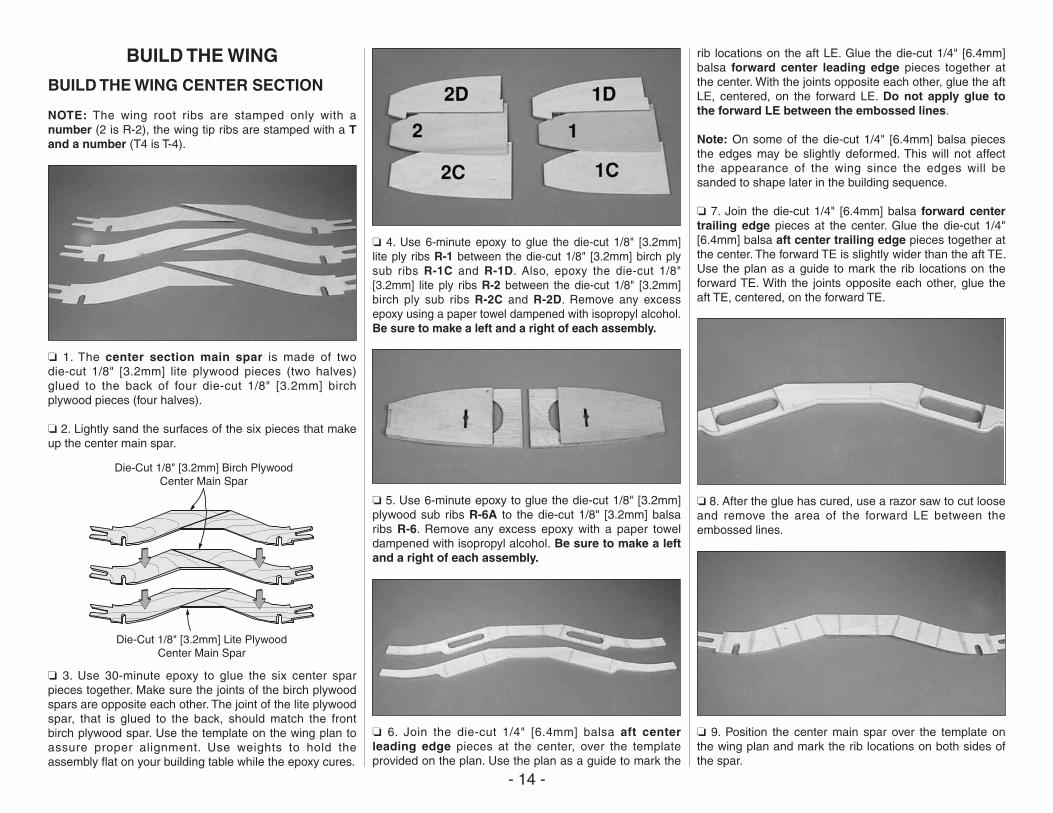
NOTE: The wing root ribs are stamped only with a number (2 is R-2), the wing tip ribs are stamped with a T and a number (T4 is T-4).
❏ 1. The center section main spar is made of two die-cut 1/8" [3.2mm] lite plywood pieces (two halves) glued to the back of four die-cut 1/8" [3.2mm] birch plywood pieces (four halves).
❏ 2. Lightly sand the surfaces of the six pieces that make up the center main spar.
Die-Cut 1/8" [3.2mm] Birch PlywoodCenter Main Spar
Die-Cut 1/8" [3.2mm] Lite PlywoodCenter Main Spar
❏ 3. Use 30-minute epoxy to glue the six center spar pieces together. Make sure the joints of the birch plywood spars are opposite each other. The joint of the lite plywood spar, that is glued to the back, should match the front birch plywood spar. Use the template on the wing plan to assure proper alignment. Use weights to hold the assembly flat on your building table while the epoxy cures.
❏ 4. Use 6-minute epoxy to glue the die-cut 1/8" [3.2mm] lite ply ribs R-1 between the die-cut 1/8" [3.2mm] birch ply sub ribs R-1C and R-1D. Also, epoxy the die-cut 1/8" [3.2mm] lite ply ribs R-2 between the die-cut 1/8" [3.2mm] birch ply sub ribs R-2C and R-2D. Remove any excess epoxy using a paper towel dampened with isopropyl alcohol. Be sure to make a left and a right of each assembly.
❏ 5. Use 6-minute epoxy to glue the die-cut 1/8" [3.2mm] plywood sub ribs R-6A to the die-cut 1/8" [3.2mm] balsa ribs R-6. Remove any excess epoxy with a paper towel dampened with isopropyl alcohol. Be sure to make a left and a right of each assembly.
❏ 6. Join the die-cut 1/4" [6.4mm] balsa aft center leading edge pieces at the center, over the template provided on the plan. Use the plan as a guide to mark the
rib locations on the aft LE. Glue the die-cut 1/4" [6.4mm] balsa forward center leading edge pieces together at the center. With the joints opposite each other, glue the aft LE, centered, on the forward LE. Do not apply glue to the forward LE between the embossed lines.
Note: On some of the die-cut 1/4" [6.4mm] balsa pieces the edges may be slightly deformed. This will not affect the appearance of the wing since the edges will be sanded to shape later in the building sequence.
❏ 7. Join the die-cut 1/4" [6.4mm] balsa forward center trailing edge pieces at the center. Glue the die-cut 1/4" [6.4mm] balsa aft center trailing edge pieces together at the center. The forward TE is slightly wider than the aft TE. Use the plan as a guide to mark the rib locations on the forward TE. With the joints opposite each other, glue the aft TE, centered, on the forward TE.
❏ 8. After the glue has cured, use a razor saw to cut loose and remove the area of the forward LE between the embossed lines.
❏ 9. Position the center main spar over the template on the wing plan and mark the rib locations on both sides of the spar.
- 15 -
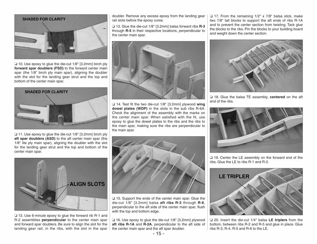
❏ 10. Use epoxy to glue the die-cut 1/8" [3.2mm] birch ply forward spar doublers (FSD) to the forward center main spar (the 1/8" birch ply main spar), aligning the doubler with the slot for the landing gear strut and the top and bottom of the center main spar.
❏ 11. Use epoxy to glue the die-cut 1/8" [3.2mm] birch ply aft spar doublers (ASD) to the aft center main spar (the 1/8" lite ply main spar), aligning the doubler with the slot for the landing gear strut and the top and bottom of the center main spar.
❏ 12. Use 6-minute epoxy to glue the forward rib R-1 and R-2 assemblies perpendicular to the center main spar and forward spar doublers. Be sure to align the slot for the landing gear rail, in the ribs, with the slot in the spar
doubler. Remove any excess epoxy from the landing gear rail slots before the epoxy cures.
❏ 13. Glue the die-cut 1/8" [3.2mm] balsa forward ribs R-3 through R-5 in their respective locations, perpendicular to the center main spar.
❏ 14. Test fit the two die-cut 1/8" [3.2mm] plywood wing dowel plates (WDP) in the slots in the sub ribs R-6A. Check the alignment of the assembly with the marks on the center main spar. When satisfied with the fit, use epoxy to glue the dowel plates to the ribs and the ribs to the main spar, making sure the ribs are perpendicular to the main spar.
❏ 15. Support the ends of the center main spar. Glue the die-cut 1/8" [3.2mm] balsa aft ribs R-3 through R-6, perpendicular to the aft side of the center main spar, flush with the top and bottom edge.
❏ 16. Use epoxy to glue the die-cut 1/8" [3.2mm] plywood aft ribs R-1A and R-2A, perpendicular to the aft side of the center main spar and the aft spar doubler.
❏ 17. From the remaining 1/2" x 7/8" balsa stick, make two 7/8" tall blocks to support the aft ends of ribs R-1A and to prevent the center section from twisting. Tack glue the blocks to the ribs. Pin the blocks to your building board and weight down the center section.
❏ 18. Glue the balsa TE assembly, centered on the aft end of the ribs.
❏ 19. Center the LE assembly on the forward end of the ribs. Glue the LE to ribs R-1 and R-2.
❏ 20. Insert the die-cut 1/4" balsa LE triplers from the bottom, between ribs R-2 and R-5 and glue in place. Glue ribs R-3, R-4, R-5 and R-6 to the LE.
- 16 -
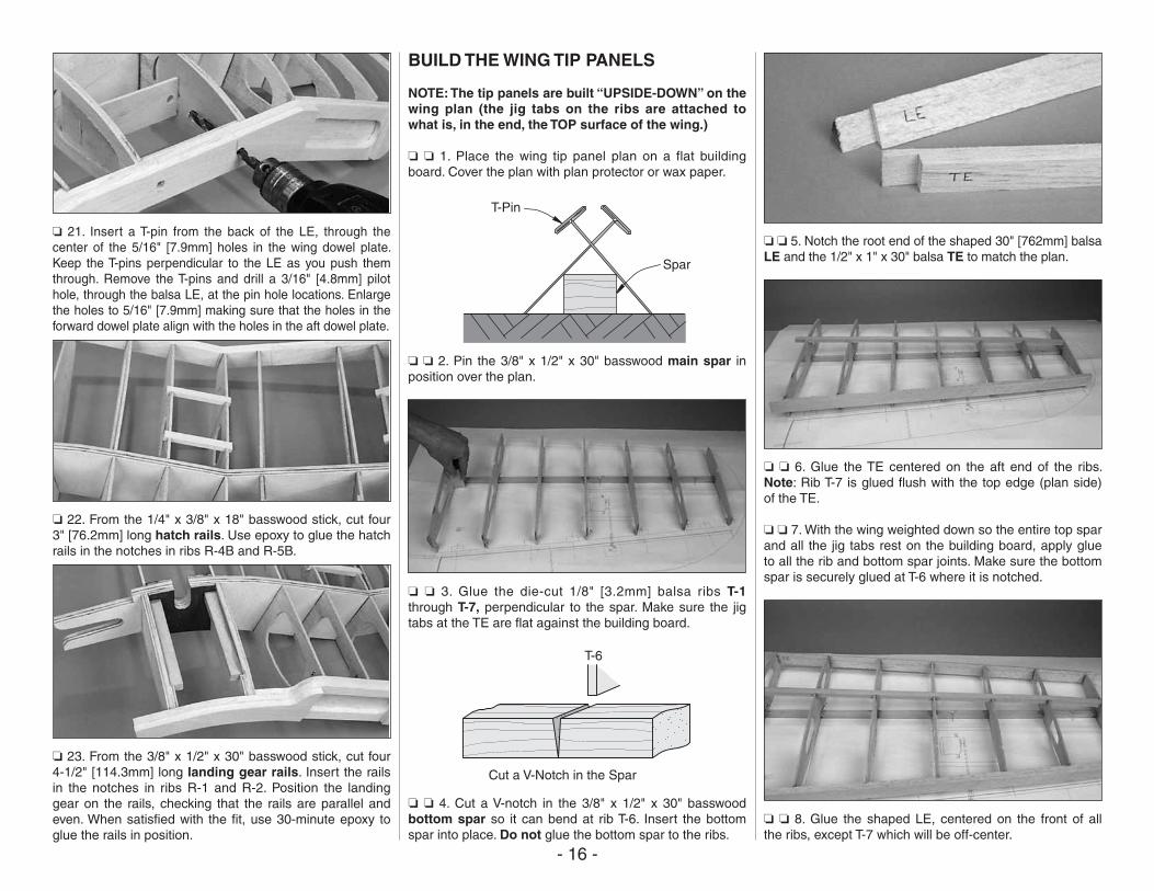
❏ 21. Insert a T-pin from the back of the LE, through the center of the 5/16" [7.9mm] holes in the wing dowel plate. Keep the T-pins perpendicular to the LE as you push them through. Remove the T-pins and drill a 3/16" [4.8mm] pilot hole, through the balsa LE, at the pin hole locations. Enlarge the holes to 5/16" [7.9mm] making sure that the holes in the forward dowel plate align with the holes in the aft dowel plate.
❏ 22. From the 1/4" x 3/8" x 18" basswood stick, cut four 3" [76.2mm] long hatch rails. Use epoxy to glue the hatch rails in the notches in ribs R-4B and R-5B.
❏ 23. From the 3/8" x 1/2" x 30" basswood stick, cut four 4-1/2" [114.3mm] long landing gear rails. Insert the rails in the notches in ribs R-1 and R-2. Position the landing gear on the rails, checking that the rails are parallel and even. When satisfied with the fit, use 30-minute epoxy to glue the rails in position.
BUILD THE WING TIP PANELS
NOTE: The tip panels are built “UPSIDE-DOWN” on the wing plan (the jig tabs on the ribs are attached to what is, in the end, the TOP surface of the wing.)
❏ ❏ 1. Place the wing tip panel plan on a flat building board. Cover the plan with plan protector or wax paper.
T-Pin
Spar
❏ ❏ 2. Pin the 3/8" x 1/2" x 30" basswood main spar in position over the plan.
❏ ❏ 3. Glue the die-cut 1/8" [3.2mm] balsa ribs T-1 through T-7, perpendicular to the spar. Make sure the jig tabs at the TE are flat against the building board.
Cut a V-Notch in the Spar
T-6
❏ ❏ 4. Cut a V-notch in the 3/8" x 1/2" x 30" basswood bottom spar so it can bend at rib T-6. Insert the bottom spar into place. Do not glue the bottom spar to the ribs.
❏ ❏ 5. Notch the root end of the shaped 30" [762mm] balsa LE and the 1/2" x 1" x 30" balsa TE to match the plan.
❏ ❏ 6. Glue the TE centered on the aft end of the ribs. Note: Rib T-7 is glued flush with the top edge (plan side) of the TE.
❏ ❏ 7. With the wing weighted down so the entire top spar and all the jig tabs rest on the building board, apply glue to all the rib and bottom spar joints. Make sure the bottom spar is securely glued at T-6 where it is notched.
❏ ❏ 8. Glue the shaped LE, centered on the front of all the ribs, except T-7 which will be off-center.
- 17 -
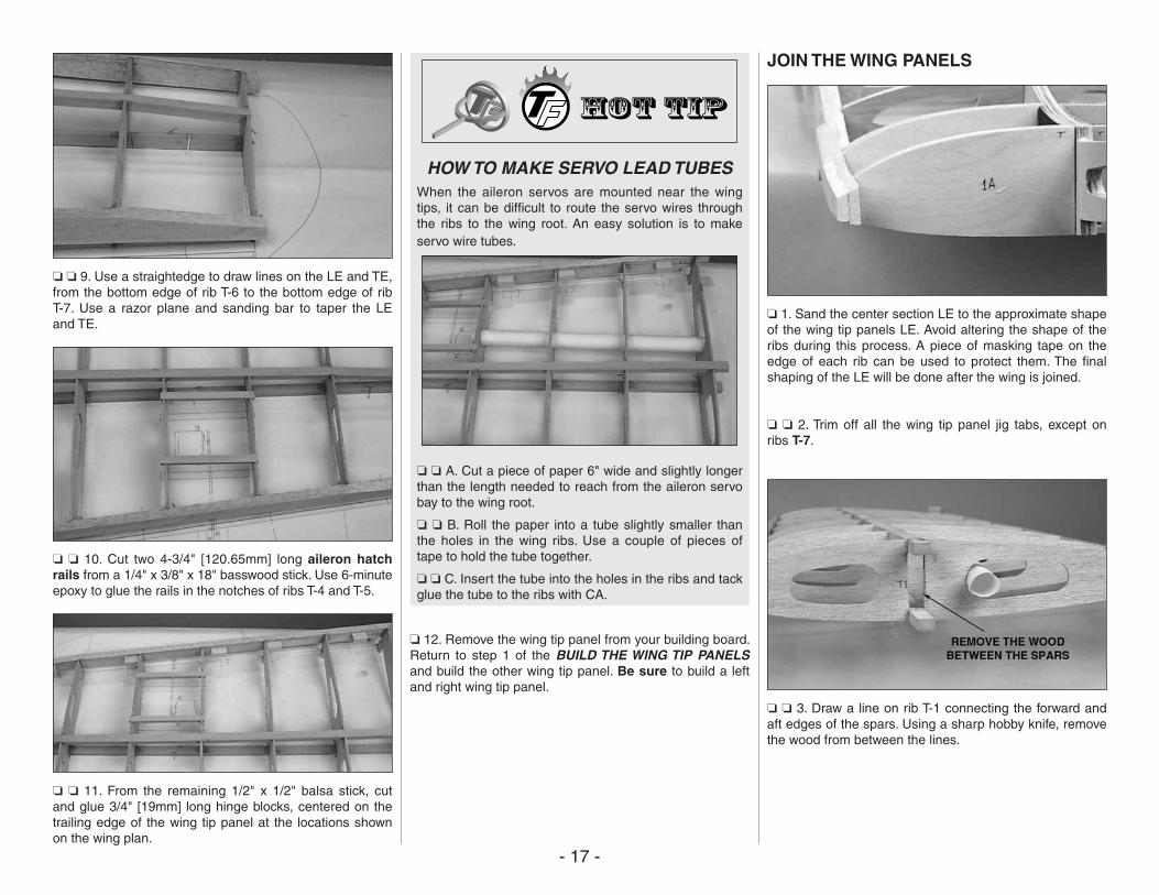
❏ ❏ 9. Use a straightedge to draw lines on the LE and TE, from the bottom edge of rib T-6 to the bottom edge of rib T-7. Use a razor plane and sanding bar to taper the LE and TE.
❏ ❏ 10. Cut two 4-3/4" [120.65mm] long aileron hatch rails from a 1/4" x 3/8" x 18" basswood stick. Use 6-minute epoxy to glue the rails in the notches of ribs T-4 and T-5.
❏ ❏ 11. From the remaining 1/2" x 1/2" balsa stick, cut and glue 3/4" [19mm] long hinge blocks, centered on the trailing edge of the wing tip panel at the locations shown on the wing plan.
HOW TO MAKE SERVO LEAD TUBESWhen the aileron servos are mounted near the wing tips, it can be difficult to route the servo wires through the ribs to the wing root. An easy solution is to make servo wire tubes.
❏ ❏ A. Cut a piece of paper 6" wide and slightly longer than the length needed to reach from the aileron servo bay to the wing root.
❏ ❏ B. Roll the paper into a tube slightly smaller than the holes in the wing ribs. Use a couple of pieces of tape to hold the tube together.
❏ ❏ C. Insert the tube into the holes in the ribs and tack glue the tube to the ribs with CA.
❏ 12. Remove the wing tip panel from your building board. Return to step 1 of the BUILD THE WING TIP PANELS and build the other wing tip panel. Be sure to build a left and right wing tip panel.
JOIN THE WING PANELS
❏ 1. Sand the center section LE to the approximate shape of the wing tip panels LE. Avoid altering the shape of the ribs during this process. A piece of masking tape on the edge of each rib can be used to protect them. The final shaping of the LE will be done after the wing is joined.
❏ ❏ 2. Trim off all the wing tip panel jig tabs, except on ribs T-7.
❏ ❏ 3. Draw a line on rib T-1 connecting the forward and aft edges of the spars. Using a sharp hobby knife, remove the wood from between the lines.
- 18 -
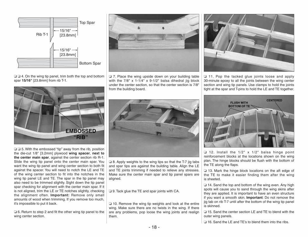
15/16"[23.8mm]
15/16"[23.8mm]
Rib T-1
Top Spar
Bottom Spar
❏ ❏ 4. On the wing tip panel, trim both the top and bottom spar 15/16" [23.8mm] from rib T-1.
❏ ❏ 5. With the embossed “tip” away from the rib, position the die-cut 1/8" [3.2mm] plywood wing spacer, next to the center main spar, against the center section rib R-1. Slide the wing tip panel onto the center main spar. You want the wing tip panel and wing center section to both fit against the spacer. You will need to notch the LE and TE of the wing center section to fit into the notches in the wing tip panel LE and TE. The spar in the tip panel may also need to be trimmed slightly. Sight down the tip panel spar checking for alignment with the center main spar. If it is not aligned, trim the LE or TE notches slightly, checking the alignment often. Important: Remove only small amounts of wood when trimming. If you remove too much, it’s impossible to put it back.
❏ 6. Return to step 2 and fit the other wing tip panel to the wing center section.
❏ 7. Place the wing upside down on your building table with the 7/8" x 1-1/4" x 9-1/2" balsa dihedral jig block under the center section, so that the center section is 7/8" from the building board.
❏ 8. Apply weights to the wing tips so that the T-7 jig tabs and spar tips are against the building table. Align the LE and TE joints trimming if needed to relieve any stresses. Make sure the center main spar and tip panel spars are aligned.
❏ 9. Tack glue the TE and spar joints with CA.
❏ 10. Remove the wing tip weights and look at the entire wing. Make sure there are no twists in the wing. If there are any problems, pop loose the wing joints and realign them.
❏ 11. Pop the tacked glue joints loose and apply 30-minute epoxy to all the joints between the wing center section and wing tip panels. Use clamps to hold the joints tight at the spar and T-pins to hold the LE and TE together.
❏ 12. Install the 1/2" x 1/2" balsa hinge point reinforcement blocks at the locations shown on the wing plan. The hinge blocks should be flush with the bottom of the TE along the flaps.
❏ 13. Mark the hinge block locations on the aft edge of the TE to make it easier finding them after the wing is sheeted.
❏ 14. Sand the top and bottom of the wing even. Any high spots will cause you to sand through the wing skins after they are applied. It is important to have an even structure if you want a smooth skin. Important: Do not remove the jig tab on rib T-7 until after the bottom of the wing tip panel is skinned.
❏ 15. Sand the center section LE and TE to blend with the outer wing panels.
❏ 16. Sand the LE and TE’s to blend them into the ribs.
- 19 -
SHEET THE WING PANELS
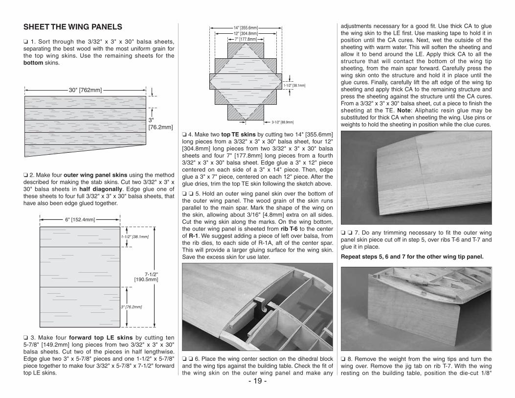
❏ 1. Sort through the 3/32" x 3" x 30" balsa sheets, separating the best wood with the most uniform grain for the top wing skins. Use the remaining sheets for the bottom skins.
30" [762mm]
3"[76.2mm]
❏ 2. Make four outer wing panel skins using the method described for making the stab skins. Cut two 3/32" x 3" x 30" balsa sheets in half diagonally. Edge glue one of these sheets to four full 3/32" x 3" x 30" balsa sheets, that have also been edge glued together.
6" [152.4mm]
1-1/2" [38.1mm]
7-1/2"[190.5mm]
3" [76.2mm]
❏ 3. Make four forward top LE skins by cutting ten 5-7/8" [149.2mm] long pieces from two 3/32" x 3" x 30" balsa sheets. Cut two of the pieces in half lengthwise. Edge glue two 3" x 5-7/8" pieces and one 1-1/2" x 5-7/8" piece together to make four 3/32" x 5-7/8" x 7-1/2" forward top LE skins.
7" [177.8mm]
3-1/2" [88.9mm]
1-1/2" [38.1mm]
12" [304.8mm]14" [355.6mm]
❏ 4. Make two top TE skins by cutting two 14" [355.6mm] long pieces from a 3/32" x 3" x 30" balsa sheet, four 12" [304.8mm] long pieces from two 3/32" x 3" x 30" balsa sheets and four 7" [177.8mm] long pieces from a fourth 3/32" x 3" x 30" balsa sheet. Edge glue a 3" x 12" piece centered on each side of a 3" x 14" piece. Then, edge glue a 3" x 7" piece, centered on each 12" piece. After the glue dries, trim the top TE skin following the sketch above.
❏ ❏ 5. Hold an outer wing panel skin over the bottom of the outer wing panel. The wood grain of the skin runs parallel to the main spar. Mark the shape of the wing on the skin, allowing about 3/16" [4.8mm] extra on all sides. Cut the wing skin along the marks. On the wing bottom, the outer wing panel is sheeted from rib T-6 to the center of R-1. We suggest adding a piece of left over balsa, from the rib dies, to each side of R-1A, aft of the center spar. This will provide a larger gluing surface for the wing skin. Save the excess skin for use later.
❏ ❏ 6. Place the wing center section on the dihedral block and the wing tips against the building table. Check the fit of the wing skin on the outer wing panel and make any
adjustments necessary for a good fit. Use thick CA to glue the wing skin to the LE first. Use masking tape to hold it in position until the CA cures. Next, wet the outside of the sheeting with warm water. This will soften the sheeting and allow it to bend around the LE. Apply thick CA to all the structure that will contact the bottom of the wing tip sheeting, from the main spar forward. Carefully press the wing skin onto the structure and hold it in place until the glue cures. Finally, carefully lift the aft edge of the wing tip sheeting and apply thick CA to the remaining structure and press the sheeting against the structure until the CA cures. From a 3/32" x 3" x 30" balsa sheet, cut a piece to finish the sheeting at the TE. Note: Aliphatic resin glue may be substituted for thick CA when sheeting the wing. Use pins or weights to hold the sheeting in position while the clue cures.
❏ ❏ 7. Do any trimming necessary to fit the outer wing panel skin piece cut off in step 5, over ribs T-6 and T-7 and glue it in place.
Repeat steps 5, 6 and 7 for the other wing tip panel.
❏ 8. Remove the weight from the wing tips and turn the wing over. Remove the jig tab on rib T-7. With the wing resting on the building table, position the die-cut 1/8"
- 20 -
[3.2mm] plywood wing jigs under the wing tips at T-7 and the 1-1/4" x 1-3/4" x 3-1/4" balsa block under the wing center section TE. The wing tips must be seated on the wing jigs and the jigs against the building table in order to provide the proper amount of washout in the wing tips, when sheeted. Note: The wing jigs can be tack glued to the excess bottom sheeting, 1/16" [1.6mm] past rib T-7.
❏ 9. Before applying the top skin, rough cut the bottom skin from over the aileron hatch openings.
❏ ❏ 10. Hold an outer wing panel skin over the top of the outer wing panel. The wood grain of the skin runs parallel to the main spar. Mark the shape of the wing on the skin, allowing about 3/16" [4.8mm] extra on all sides. On the wing top, the outer wing panel is skinned from rib T-7 to the center of R-1. We again, suggest adding a piece of left over balsa to each side of R-1A.
❏ ❏ 11. Use thick CA to glue the wing skin to the LE first. Use masking tape to hold it in position until the CA cures. Next, wet the outside of the skin with warm water. Apply thick CA to all the structure that will contact the bottom of the wing skin from the main spar forward. Carefully press the wing skin onto the structure and hold it in place until the glue cures. Finally, carefully lift the aft edge of the wing tip sheeting and apply thick CA to the remaining structure and press the sheeting against the structure until the CA cures. Use the remaining 3/32" x 3" balsa sheet from step 4 to complete the sheeting at the TE .
Repeat steps 10 and 11 for the other wing tip panel.
❏ 12. Trim and sand the top and bottom wing tip skin flush with the LE, TE and wing tip rib T-7.
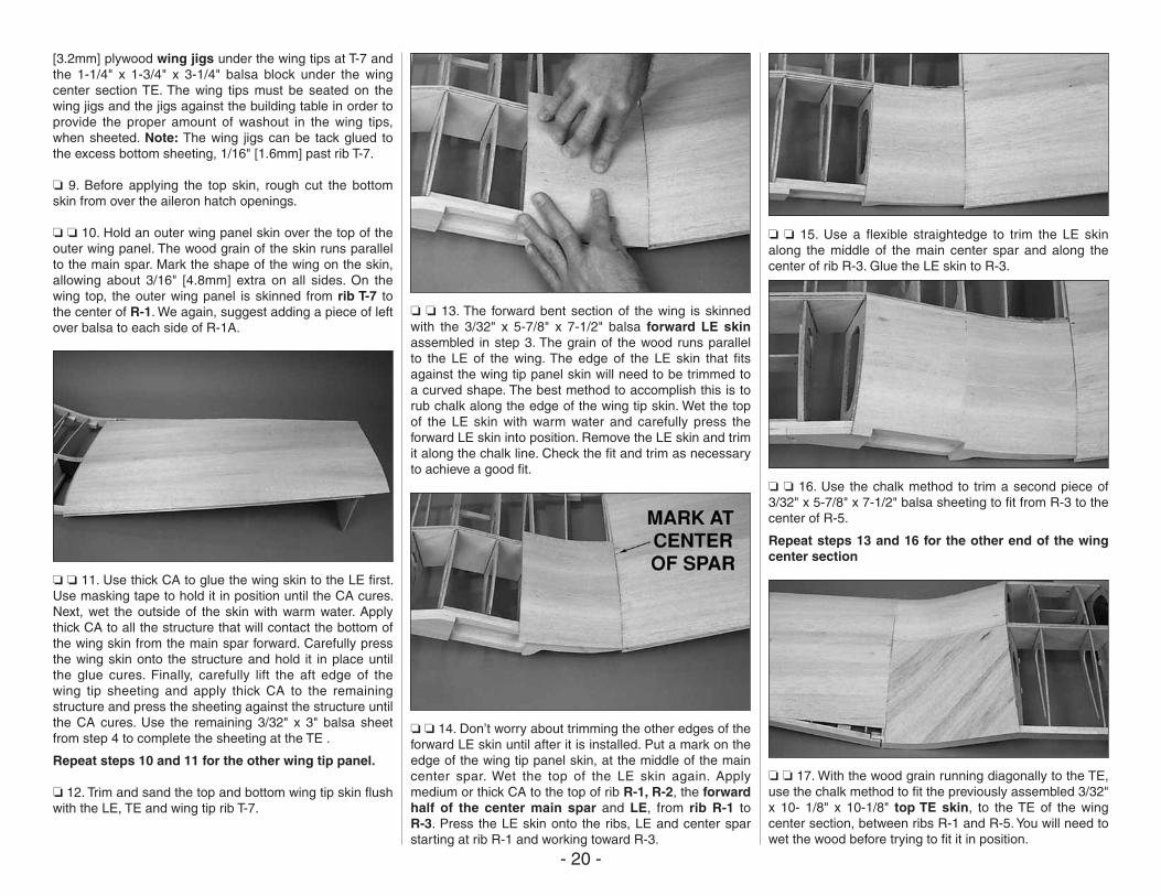
❏ ❏ 13. The forward bent section of the wing is skinned with the 3/32" x 5-7/8" x 7-1/2" balsa forward LE skin assembled in step 3. The grain of the wood runs parallel to the LE of the wing. The edge of the LE skin that fits against the wing tip panel skin will need to be trimmed to a curved shape. The best method to accomplish this is to rub chalk along the edge of the wing tip skin. Wet the top of the LE skin with warm water and carefully press the forward LE skin into position. Remove the LE skin and trim it along the chalk line. Check the fit and trim as necessary to achieve a good fit.
❏ ❏ 14. Don’t worry about trimming the other edges of the forward LE skin until after it is installed. Put a mark on the edge of the wing tip panel skin, at the middle of the main center spar. Wet the top of the LE skin again. Apply medium or thick CA to the top of rib R-1, R-2, the forward half of the center main spar and LE, from rib R-1 to R-3. Press the LE skin onto the ribs, LE and center spar starting at rib R-1 and working toward R-3.
❏ ❏ 15. Use a flexible straightedge to trim the LE skin along the middle of the main center spar and along the center of rib R-3. Glue the LE skin to R-3.
❏ ❏ 16. Use the chalk method to trim a second piece of 3/32" x 5-7/8" x 7-1/2" balsa sheeting to fit from R-3 to the center of R-5.
Repeat steps 13 and 16 for the other end of the wing center section
❏ ❏ 17. With the wood grain running diagonally to the TE, use the chalk method to fit the previously assembled 3/32" x 10- 1/8" x 10-1/8" top TE skin, to the TE of the wing center section, between ribs R-1 and R-5. You will need to wet the wood before trying to fit it in position.
- 21 -
❏ ❏ 18. When satisfied with the fit of the top TE skin, wet it again; apply medium or thick CA on ribs R-1 thorough R-4, the center spar and the TE between R-1 and R-5. Press the TE skin onto the structure and hold it in position until the CA cures.
❏ ❏ 19. After the CA cures, trim the top TE skin to the center of rib R-5 and flush with the TE. Glue the TE skin to rib R-5.
Repeat steps 17 through 19 for the other end of the wing center section
❏ 20. Use 3/32" x 3" x 30" balsa sheets to skin the top of the wing center section between the R-5 ribs.
❏ 21. Turn the wing over and apply CA to any top skins that may not be glued securely to the structure.
SHEET THE BOTTOM CENTER SECTION
❏ 1. We suggest adding a piece of left over 1/8" [3.2mm] balsa, from the rib dies, to the side of ribs R-4 and R-5,
between the servo hatch rails. This will provide a larger gluing surface for the bottom wing skins. Note: All of the bottom center skins are cut from 3/32" x 3" x 24" balsa sheets. You may find it faster and easier to skin both the left and right sides at the same time to avoid having to determine skin shapes twice.
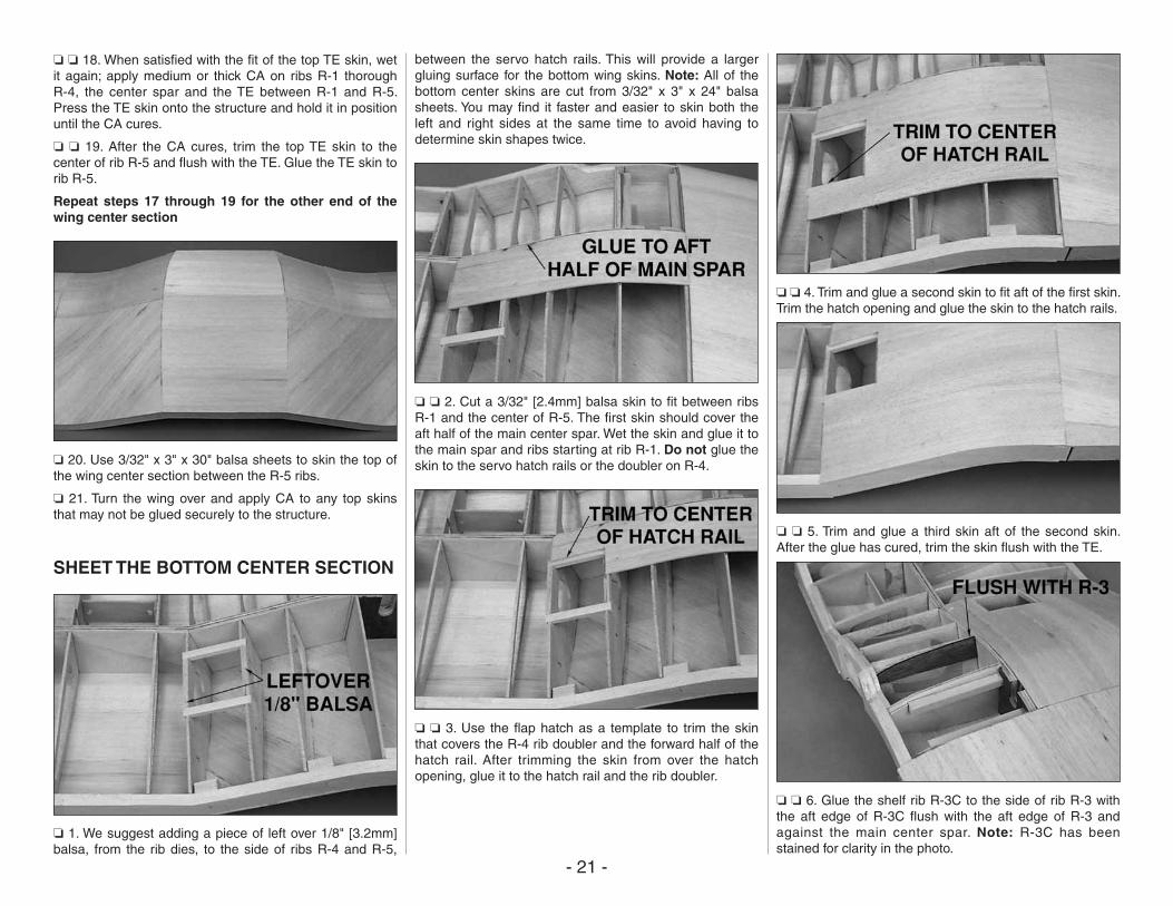
❏ ❏ 2. Cut a 3/32" [2.4mm] balsa skin to fit between ribs R-1 and the center of R-5. The first skin should cover the aft half of the main center spar. Wet the skin and glue it to the main spar and ribs starting at rib R-1. Do not glue the skin to the servo hatch rails or the doubler on R-4.
❏ ❏ 3. Use the flap hatch as a template to trim the skin that covers the R-4 rib doubler and the forward half of the hatch rail. After trimming the skin from over the hatch opening, glue it to the hatch rail and the rib doubler.
❏ ❏ 4. Trim and glue a second skin to fit aft of the first skin. Trim the hatch opening and glue the skin to the hatch rails.
❏ ❏ 5. Trim and glue a third skin aft of the second skin. After the glue has cured, trim the skin flush with the TE.
❏ ❏ 6. Glue the shelf rib R-3C to the side of rib R-3 with the aft edge of R-3C flush with the aft edge of R-3 and against the main center spar. Note: R-3C has been stained for clarity in the photo.
- 22 -
❏ ❏ 7. Cut a 3/32" [2.4mm] balsa skin to fit between ribs R-1 and R-3C. The first skin should cover the forward half of the main center spar. Wet the skin and glue it to the main spar and ribs starting at rib R-1.
❏ ❏ 8. Cut a second 3/32" [2.4mm] balsa skin to fit between ribs R-1 and R-3C. Trim the skin to fit around the bump for the oil cooler. Wet the sheet and glue it to the LE and ribs. Use a leftover piece of 3/32" [2.4mm] balsa to finish the LE.
❏ ❏ 9. Cut 3/32" [92.4mm] balsa skin to fit between ribs R-3 and the center of R-5, from the center of the main spar to the LE.
❏ 10. Sand the wing skin flush with the LE, TE and tip ribs R-7T.
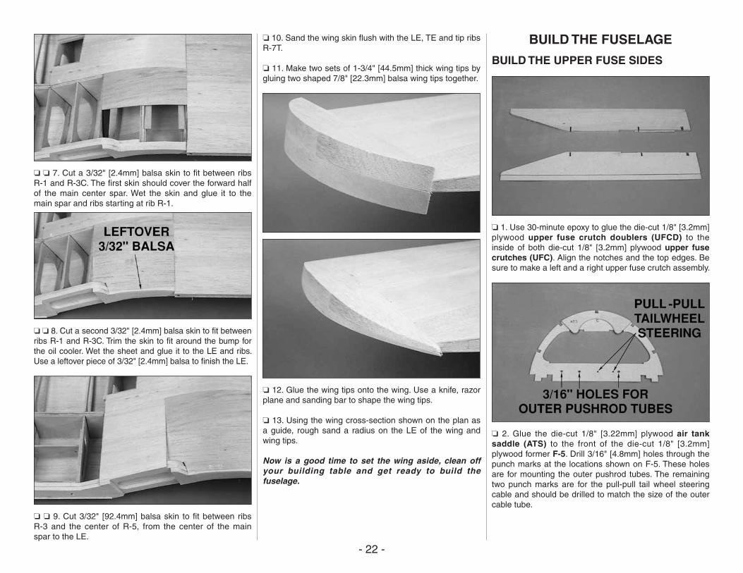
❏ 11. Make two sets of 1-3/4" [44.5mm] thick wing tips by gluing two shaped 7/8" [22.3mm] balsa wing tips together.
❏ 12. Glue the wing tips onto the wing. Use a knife, razor plane and sanding bar to shape the wing tips.
❏ 13. Using the wing cross-section shown on the plan as a guide, rough sand a radius on the LE of the wing and wing tips.
Now is a good time to set the wing aside, clean off your building table and get ready to build the fuselage.
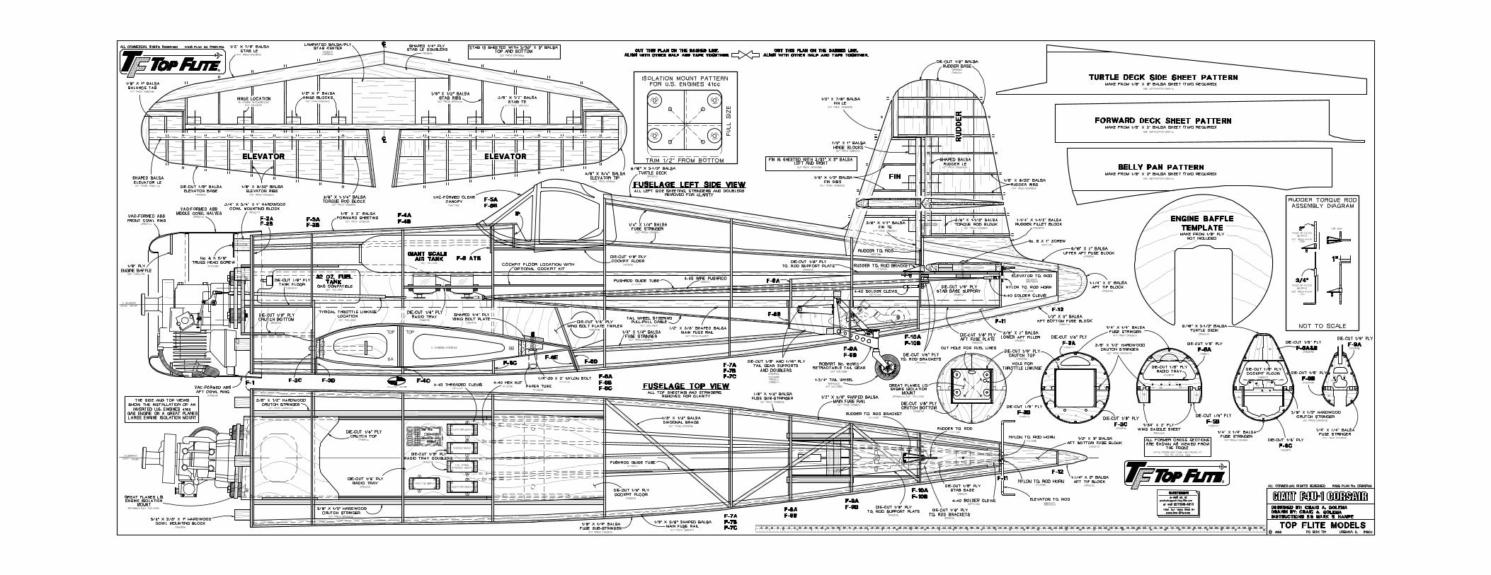
BUILD THE FUSELAGE
BUILD THE UPPER FUSE SIDES
❏ 1. Use 30-minute epoxy to glue the die-cut 1/8" [3.2mm] plywood upper fuse crutch doublers (UFCD) to the inside of both die-cut 1/8" [3.2mm] plywood upper fuse crutches (UFC). Align the notches and the top edges. Be sure to make a left and a right upper fuse crutch assembly.
❏ 2. Glue the die-cut 1/8" [3.22mm] plywood air tank saddle (ATS) to the front of the die-cut 1/8" [3.2mm] plywood former F-5. Drill 3/16" [4.8mm] holes through the punch marks at the locations shown on F-5. These holes are for mounting the outer pushrod tubes. The remaining two punch marks are for the pull-pull tail wheel steering cable and should be drilled to match the size of the outer cable tube.
- 23 -
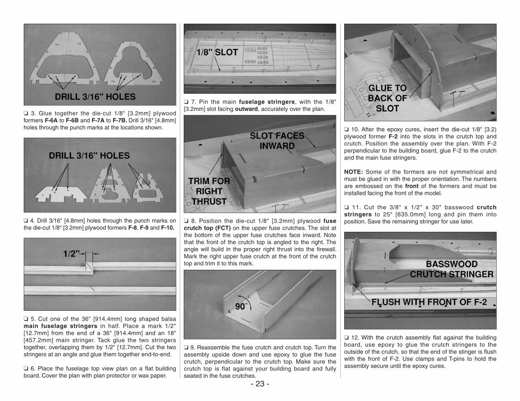
❏ 3. Glue together the die-cut 1/8" [3.2mm] plywood formers F-6A to F-6B and F-7A to F-7B. Drill 3/16" [4.8mm] holes through the punch marks at the locations shown.
❏ 4. Drill 3/16" [4.8mm] holes through the punch marks on the die-cut 1/8" [3.2mm] plywood formers F-8, F-9 and F-10.
❏ 5. Cut one of the 36" [914.4mm] long shaped balsa main fuselage stringers in half. Place a mark 1/2" [12.7mm] from the end of a 36" [914.4mm] and an 18" [457.2mm] main stringer. Tack glue the two stringers together, overlapping them by 1/2" [12.7mm]. Cut the two stringers at an angle and glue them together end-to-end.
❏ 6. Place the fuselage top view plan on a flat building board. Cover the plan with plan protector or wax paper.
❏ 7. Pin the main fuselage stringers, with the 1/8" [3.2mm] slot facing outward, accurately over the plan.
❏ 8. Position the die-cut 1/8" [3.2mm] plywood fuse crutch top (FCT) on the upper fuse crutches. The slot at the bottom of the upper fuse crutches face inward. Note that the front of the crutch top is angled to the right. The angle will build in the proper right thrust into the firewall. Mark the right upper fuse crutch at the front of the crutch top and trim it to this mark.
❏ 9. Reassemble the fuse crutch and crutch top. Turn the assembly upside down and use epoxy to glue the fuse crutch, perpendicular to the crutch top. Make sure the crutch top is flat against your building board and fully seated in the fuse crutches.
❏ 10. After the epoxy cures, insert the die-cut 1/8" [3.2) plywood former F-2 into the slots in the crutch top and crutch. Position the assembly over the plan. With F-2 perpendicular to the building board, glue F-2 to the crutch and the main fuse stringers.
NOTE: Some of the formers are not symmetrical and must be glued in with the proper orientation. The numbers are embossed on the front of the formers and must be installed facing the front of the model.
❏ 11. Cut the 3/8" x 1/2" x 30" basswood crutch stringers to 25" [635.0mm] long and pin them into position. Save the remaining stringer for use later.
❏ 12. With the crutch assembly flat against the building board, use epoxy to glue the crutch stringers to the outside of the crutch, so that the end of the stinger is flush with the front of F-2. Use clamps and T-pins to hold the assembly secure until the epoxy cures.
- 24 -
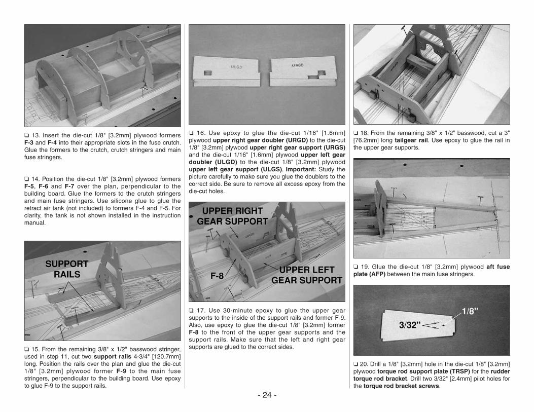
❏ 13. Insert the die-cut 1/8" [3.2mm] plywood formers F-3 and F-4 into their appropriate slots in the fuse crutch. Glue the formers to the crutch, crutch stringers and main fuse stringers.
❏ 14. Position the die-cut 1/8" [3.2mm] plywood formers F-5, F-6 and F-7 over the plan, perpendicular to the building board. Glue the formers to the crutch stringers and main fuse stringers. Use silicone glue to glue the retract air tank (not included) to formers F-4 and F-5. For clarity, the tank is not shown installed in the instruction manual.
❏ 15. From the remaining 3/8" x 1/2" basswood stringer, used in step 11, cut two support rails 4-3/4" [120.7mm] long. Position the rails over the plan and glue the die-cut 1/8" [3.2mm] plywood former F-9 to the main fuse stringers, perpendicular to the building board. Use epoxy to glue F-9 to the support rails.
❏ 16. Use epoxy to glue the die-cut 1/16" [1.6mm] plywood upper right gear doubler (URGD) to the die-cut 1/8" [3.2mm] plywood upper right gear support (URGS) and the die-cut 1/16" [1.6mm] plywood upper left gear doubler (ULGD) to the die-cut 1/8" [3.2mm] plywood upper left gear support (ULGS). Important: Study the picture carefully to make sure you glue the doublers to the correct side. Be sure to remove all excess epoxy from the die-cut holes.
❏ 17. Use 30-minute epoxy to glue the upper gear supports to the inside of the support rails and former F-9. Also, use epoxy to glue the die-cut 1/8" [3.2mm] former F-8 to the front of the upper gear supports and the support rails. Make sure that the left and right gear supports are glued to the correct sides.
❏ 18. From the remaining 3/8" x 1/2" basswood, cut a 3" [76.2mm] long tailgear rail. Use epoxy to glue the rail in the upper gear supports.
❏ 19. Glue the die-cut 1/8" [3.2mm] plywood aft fuse plate (AFP) between the main fuse stringers.
❏ 20. Drill a 1/8" [3.2mm] hole in the die-cut 1/8" [3.2mm] plywood torque rod support plate (TRSP) for the rudder torque rod bracket. Drill two 3/32" [2.4mm] pilot holes for the torque rod bracket screws.
- 25 -
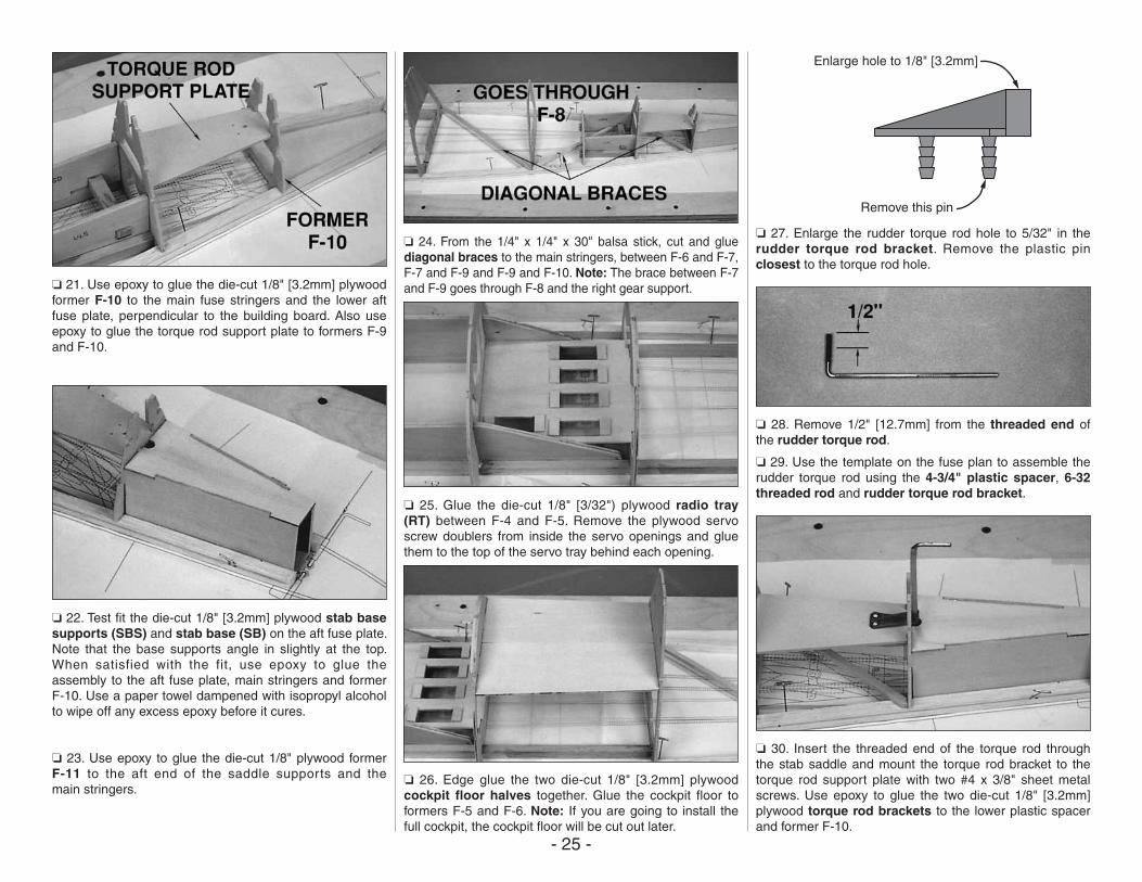
❏ 21. Use epoxy to glue the die-cut 1/8" [3.2mm] plywood former F-10 to the main fuse stringers and the lower aft fuse plate, perpendicular to the building board. Also use epoxy to glue the torque rod support plate to formers F-9 and F-10.
❏ 22. Test fit the die-cut 1/8" [3.2mm] plywood stab base supports (SBS) and stab base (SB) on the aft fuse plate. Note that the base supports angle in slightly at the top. When satisfied with the fit, use epoxy to glue the assembly to the aft fuse plate, main stringers and former F-10. Use a paper towel dampened with isopropyl alcohol to wipe off any excess epoxy before it cures.
❏ 23. Use epoxy to glue the die-cut 1/8" plywood former F-11 to the aft end of the saddle supports and the main stringers.
❏ 24. From the 1/4" x 1/4" x 30" balsa stick, cut and glue diagonal braces to the main stringers, between F-6 and F-7, F-7 and F-9 and F-9 and F-10. Note: The brace between F-7 and F-9 goes through F-8 and the right gear support.
❏ 25. Glue the die-cut 1/8" [3/32") plywood radio tray (RT) between F-4 and F-5. Remove the plywood servo screw doublers from inside the servo openings and glue them to the top of the servo tray behind each opening.
❏ 26. Edge glue the two die-cut 1/8" [3.2mm] plywood cockpit floor halves together. Glue the cockpit floor to formers F-5 and F-6. Note: If you are going to install the full cockpit, the cockpit floor will be cut out later.
Enlarge hole to 1/8" [3.2mm]
Remove this pin
❏ 27. Enlarge the rudder torque rod hole to 5/32" in the rudder torque rod bracket. Remove the plastic pin closest to the torque rod hole.
❏ 28. Remove 1/2" [12.7mm] from the threaded end of the rudder torque rod.
❏ 29. Use the template on the fuse plan to assemble the rudder torque rod using the 4-3/4" plastic spacer, 6-32 threaded rod and rudder torque rod bracket.
❏ 30. Insert the threaded end of the torque rod through the stab saddle and mount the torque rod bracket to the torque rod support plate with two #4 x 3/8" sheet metal screws. Use epoxy to glue the two die-cut 1/8" [3.2mm] plywood torque rod brackets to the lower plastic spacer and former F-10.
- 26 -
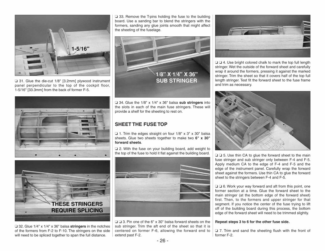
❏ 31. Glue the die-cut 1/8" [3.2mm] plywood instrument panel perpendicular to the top of the cockpit floor, 1-5/16" [33.3mm] from the back of former F-5.
❏ 32. Glue 1/4" x 1/4" x 36" balsa stringers in the notches of the formers from F-2 to F-10. The stringers on the side will need to be spliced together to span the full distance.
❏ 33. Remove the T-pins holding the fuse to the building board. Use a sanding bar to blend the stringers with the formers, sanding any glue joints smooth that might affect the sheeting of the fuselage.
❏ 34. Glue the 1/8" x 1/4" x 36" balsa sub stringers into the slots in each of the main fuse stringers. These will provide a shelf for the sheeting to rest on.
SHEET THE FUSE TOP
❏ 1. Trim the edges straight on four 1/8" x 3" x 30" balsa sheets. Glue two sheets together to make two 6" x 30" forward sheets.
❏ 2. With the fuse on your building board, add weight to the top of the fuse to hold it flat against the building board.
❏ ❏ 3. Pin one of the 6" x 30" balsa forward sheets on the sub stringer. Trim the aft end of the sheet so that it is centered on former F-6, allowing the forward end to extend past F-2.
❏ ❏ 4. Use bright colored chalk to mark the top full length stringer. Wet the outside of the forward sheet and carefully wrap it around the formers, pressing it against the marked stringer. Trim the sheet so that it covers half of the top full length stringer. Test fit the forward sheet to the fuse frame and trim as necessary.
❏ ❏ 5. Use thin CA to glue the forward sheet to the main fuse stringer and sub stringer only between F-4 and F-5. Apply medium CA to the edge of F-4 and F-5 and the edge of the instrument panel. Carefully wrap the forward sheet against the formers. Use thin CA to glue the forward sheet to the stringers between F-4 and F-5.
❏ ❏ 6. Work your way forward and aft from this point, one former section at a time. Glue the forward sheet to the main stringer (at the bottom edge of the forward sheet) first. Then, to the formers and upper stringer for that segment. If you notice the center of the fuse trying to lift off of the building board during this process, the bottom edge of the forward sheet will need to be trimmed slightly.
Repeat steps 3 to 6 for the other fuse side.
❏ 7. Trim and sand the sheeting flush with the front of former F-2.
- 27 -
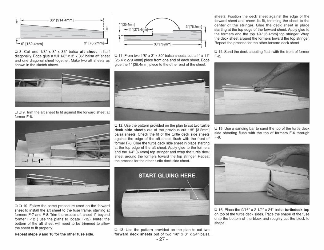
36" [914.4mm]
6" [152.4mm] 3" [76.2mm]
❏ 8. Cut one 1/8" x 3" x 36" balsa aft sheet in half diagonally. Edge glue a full 1/8" x 3" x 36" balsa aft sheet and one diagonal sheet together. Make two aft sheets as shown in the sketch above.
❏ ❏ 9. Trim the aft sheet to fit against the forward sheet at former F-6.
❏ ❏ 10. Follow the same procedure used on the forward sheet to install the aft sheet to the fuse frame, starting at formers F-7 and F-8. Trim the excess aft sheet 1" beyond former F-12 ( use the plans to locate F-12). Note: the bottom of the aft sheet will need to be trimmed to allow the sheet to fit properly.
Repeat steps 9 and 10 for the other fuse side.
30" [762mm]
1" [25.4mm]11" [279.4mm]
3" [76.2mm]
❏ 11. From two 1/8" x 3" x 30" balsa sheets, cut a 1" x 11" [25.4 x 279.4mm] piece from one end of each sheet. Edge glue the 1" [25.4mm] piece to the other end of the sheet.
❏ 12. Use the pattern provided on the plan to cut two turtle deck side sheets out of the previous cut 1/8" [3.2mm] balsa sheets. Check the fit of the turtle deck side sheets against the edge of the aft sheet, flush with the front of former F-6. Glue the turtle deck side sheet in place starting at the top edge of the aft sheet. Apply glue to the formers and the 1/4" [6.4mm] top stringer and wrap the turtle deck sheet around the formers toward the top stringer. Repeat the process for the other turtle deck side sheet.
❏ 13. Use the pattern provided on the plan to cut two forward deck sheets out of two 1/8" x 3" x 24" balsa
sheets. Position the deck sheet against the edge of the forward sheet and check its fit, trimming the sheet to the center of the stringer. Glue the deck sheet in place starting at the top edge of the forward sheet. Apply glue to the formers and the top 1/4" [6.4mm] top stringer. Wrap the deck sheet around the formers toward the top stringer. Repeat the process for the other forward deck sheet.
❏ 14. Sand the deck sheeting flush with the front of former F-2.
❏ 15. Use a sanding bar to sand the top of the turtle deck side sheeting flush with the top of formers F-6 through F-9.
❏ 16. Place the 9/16" x 2-1/2" x 24" balsa turtledeck top on top of the turtle deck sides. Trace the shape of the fuse onto the bottom of the block and roughly cut the block to shape.
- 28 -
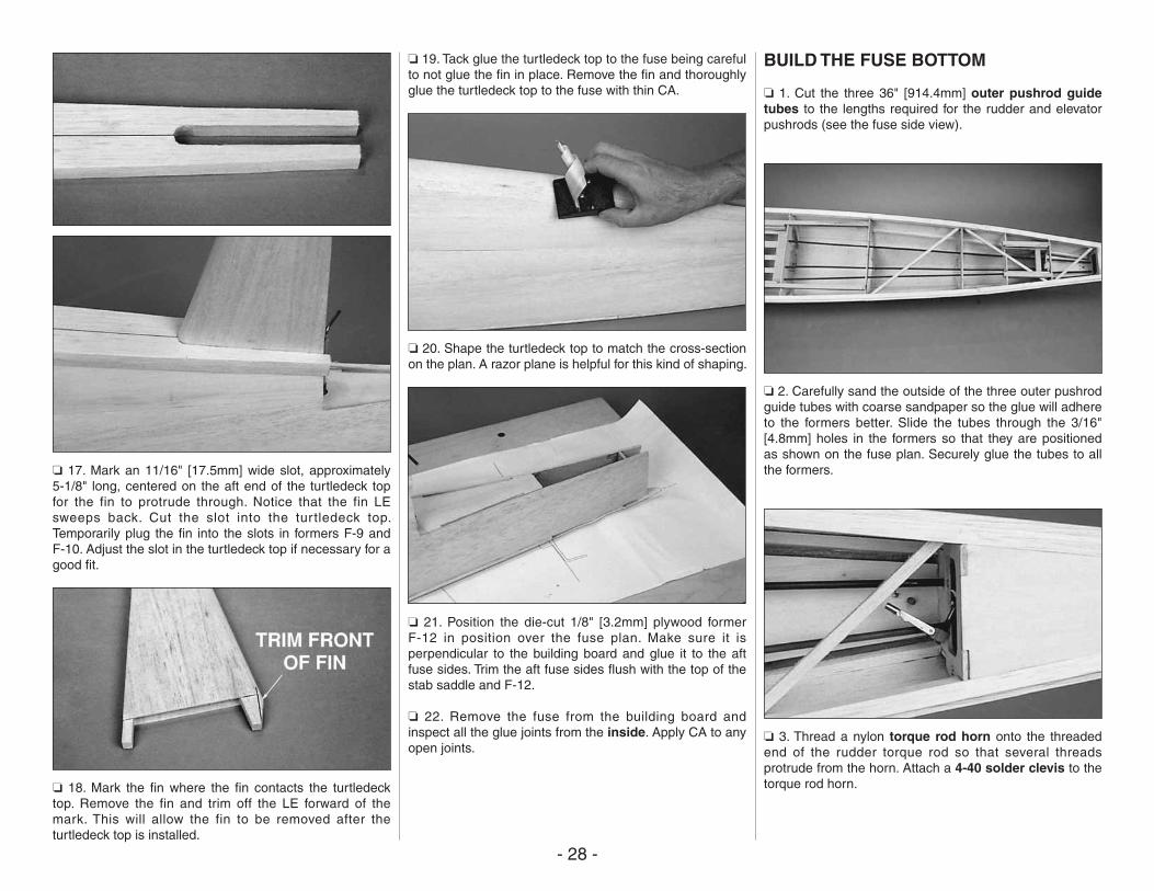
❏ 17. Mark an 11/16" [17.5mm] wide slot, approximately 5-1/8" long, centered on the aft end of the turtledeck top for the fin to protrude through. Notice that the fin LE sweeps back. Cut the slot into the turtledeck top. Temporarily plug the fin into the slots in formers F-9 and F-10. Adjust the slot in the turtledeck top if necessary for a good fit.
❏ 18. Mark the fin where the fin contacts the turtledeck top. Remove the fin and trim off the LE forward of the mark. This will allow the fin to be removed after the turtledeck top is installed.
❏ 19. Tack glue the turtledeck top to the fuse being careful to not glue the fin in place. Remove the fin and thoroughly glue the turtledeck top to the fuse with thin CA.
❏ 20. Shape the turtledeck top to match the cross-section on the plan. A razor plane is helpful for this kind of shaping.
❏ 21. Position the die-cut 1/8" [3.2mm] plywood former F-12 in position over the fuse plan. Make sure it is perpendicular to the building board and glue it to the aft fuse sides. Trim the aft fuse sides flush with the top of the stab saddle and F-12.
❏ 22. Remove the fuse from the building board and inspect all the glue joints from the inside. Apply CA to any open joints.
BUILD THE FUSE BOTTOM
❏ 1. Cut the three 36" [914.4mm] outer pushrod guide tubes to the lengths required for the rudder and elevator pushrods (see the fuse side view).
❏ 2. Carefully sand the outside of the three outer pushrod guide tubes with coarse sandpaper so the glue will adhere to the formers better. Slide the tubes through the 3/16" [4.8mm] holes in the formers so that they are positioned as shown on the fuse plan. Securely glue the tubes to all the formers.
❏ 3. Thread a nylon torque rod horn onto the threaded end of the rudder torque rod so that several threads protrude from the horn. Attach a 4-40 solder clevis to the torque rod horn.
- 29 -
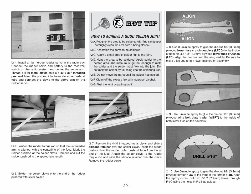
❏ 4. Install a high torque rudder servo in the radio tray. Connect the rudder servo and battery to the receiver, switch on the radio system and center the servo arm. Thread a 4-40 metal clevis onto a 4-40 x 36" threaded pushrod. Insert the pushrod into the rudder outer pushrod tube and connect the clevis to the servo arm on the rudder servo.
❏ 5. Position the rudder torque rod so that the unthreaded arm is aligned with the centerline of the fuse. Mark the rudder pushrod at the solder clevis. Remove and cut the rudder pushrod to the appropriate length.
❏ 6. Solder the solder clevis onto the end of the rudder pushrod with silver solder.
HOW TO ACHIEVE A GOOD SOLDER JOINT❏ A. Roughen the area to be soldered with fine sandpaper.
Thoroughly clean the area with rubbing alcohol.
❏ B. Assemble the items to be soldered.
❏ C. Apply a small drop of solder flux to the joint.
❏ D. Heat the area to be soldered. Apply solder to the heated area. The metal must get hot enough to melt the solder and the solder must flow into the joint. Do not melt the solder by touching it to the soldering iron.
❏ E. Do not move the parts until the solder has cooled.
❏ F. Clean off the excess flux with isopropyl alcohol.
❏ G. Test the joint by pulling on it.
❏ 7. Remove the 4-40 threaded metal clevis and slide a silicone retainer over the solder clevis. Insert the rudder pushrod into the rudder outer pushrod tube from the aft end of the fuse. Attach the solder clevis to the rudder torque rod and slide the silicone retainer over the clevis. Remove the rudder servo.
❏ 8. Use 30-minute epoxy to glue the die-cut 1/8" [3.2mm] plywood lower fuse crutch doublers (LFCD) to the inside of both die-cut 1/8" [3.2mm] plywood lower fuse crutches (LFC). Align the notches and the wing saddle. Be sure to make a left and a right lower fuse crutch assembly.
❏ 9. Use 6-minute epoxy to glue the die-cut 1/8" [3.2mm] plywood wing bolt plate tripler (WBPT) to the inside of both lower fuse crutch doublers.
❏ 10. Use 6-minute epoxy to glue the die-cut 1/8" [3.2mm] plywood former F-3C to the front of the former F-3B. After the epoxy cures, drill two 5/16" [7.9mm] holes through F-3C using the holes in F-3B as guides.
- 30 -
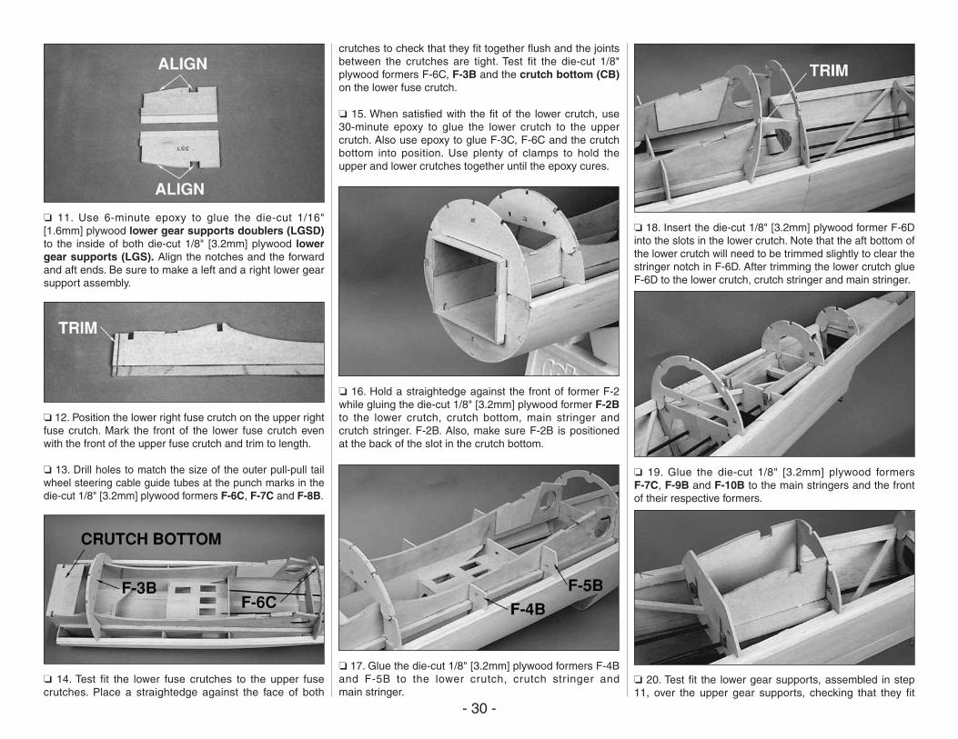
❏ 11. Use 6-minute epoxy to glue the die-cut 1/16" [1.6mm] plywood lower gear supports doublers (LGSD) to the inside of both die-cut 1/8" [3.2mm] plywood lower gear supports (LGS). Align the notches and the forward and aft ends. Be sure to make a left and a right lower gear support assembly.
❏ 12. Position the lower right fuse crutch on the upper right fuse crutch. Mark the front of the lower fuse crutch even with the front of the upper fuse crutch and trim to length.
❏ 13. Drill holes to match the size of the outer pull-pull tail wheel steering cable guide tubes at the punch marks in the die-cut 1/8" [3.2mm] plywood formers F-6C, F-7C and F-8B.
❏ 14. Test fit the lower fuse crutches to the upper fuse crutches. Place a straightedge against the face of both
crutches to check that they fit together flush and the joints between the crutches are tight. Test fit the die-cut 1/8" plywood formers F-6C, F-3B and the crutch bottom (CB) on the lower fuse crutch.
❏ 15. When satisfied with the fit of the lower crutch, use 30-minute epoxy to glue the lower crutch to the upper crutch. Also use epoxy to glue F-3C, F-6C and the crutch bottom into position. Use plenty of clamps to hold the upper and lower crutches together until the epoxy cures.
❏ 16. Hold a straightedge against the front of former F-2 while gluing the die-cut 1/8" [3.2mm] plywood former F-2B to the lower crutch, crutch bottom, main stringer and crutch stringer. F-2B. Also, make sure F-2B is positioned at the back of the slot in the crutch bottom.
❏ 17. Glue the die-cut 1/8" [3.2mm] plywood formers F-4B and F-5B to the lower crutch, crutch stringer and main stringer.
❏ 18. Insert the die-cut 1/8" [3.2mm] plywood former F-6D into the slots in the lower crutch. Note that the aft bottom of the lower crutch will need to be trimmed slightly to clear the stringer notch in F-6D. After trimming the lower crutch glue F-6D to the lower crutch, crutch stringer and main stringer.
❏ 19. Glue the die-cut 1/8" [3.2mm] plywood formers F-7C, F-9B and F-10B to the main stringers and the front of their respective formers.
❏ 20. Test fit the lower gear supports, assembled in step 11, over the upper gear supports, checking that they fit
- 31 -
flush with each other. Slide former F-8B over the lower gear supports. When satisfied with the fit, use 6-minute epoxy to glue the assembly in the fuse.
❏ 21. From the remaining 3/8" x 1/2" basswood stick, cut a 3" long tailgear rail. Use epoxy to glue the rail in the notched lower gear supports.
❏ 22. Carefully roughen the outside of the tail wheel steering guide tubes with sandpaper. Insert and glue the tubes in formers F-5 through F-8B.
❏ 23. Glue in the lower forward and aft 1/4" [6.4mm] stringers. After the CA cures, sand the forward stringers flush with F-2B and F-3B and the aft stringers flush with F-6D through F-10B.
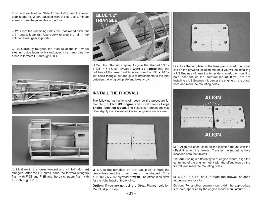
❏ 24. Use 30-minute epoxy to glue the shaped 1/4" x 1-3/8" x 5-15/16" plywood wing bolt plate into the notches of the lower crutch. Also, from the 1/2" x 1/2" x 12" balsa triangle, cut and glue reinforcements to the joint between the wing bolt plate and lower crutch.
INSTALL THE FIREWALL
The following instructions will describe the procedure for mounting a 41cc US Engine and Great Planes Large Engine Isolation Mount. The installation procedure may differ slightly if a different engine and engine mount are used.
❏ 1. Use the template on the fuse plan to mark the centerlines and the offset lines on the shaped 1/4" x 4-11/16" x 5-7/16" plywood firewall. The offset lines allow for the right thrust of the engine.
Option: If you are not using a Great Planes Isolation Mount, skip to step 3.
❏ 2. Use the template on the fuse plan to mark the offset line on the plywood isolation mount. If you will be installing a US Engines 41, use the template to mark the mounting hole locations on the isolation mount. If you are not installing a US Engines 41, center the engine on the offset lines and mark the mounting holes.
❏ 3. Align the offset lines on the isolation mount with the offset lines on the firewall. Transfer the mounting hole locations onto the firewall.
Option: If using a different type of engine mount, align the centerline of the engine mount with the offset lines on the firewall and mark the mounting holes.
❏ 4. Drill a 5/16" hole through the firewall at each mounting hole location.
Option: For another engine mount, drill the appropriate size hole, specified by the engine mount manufacturer.
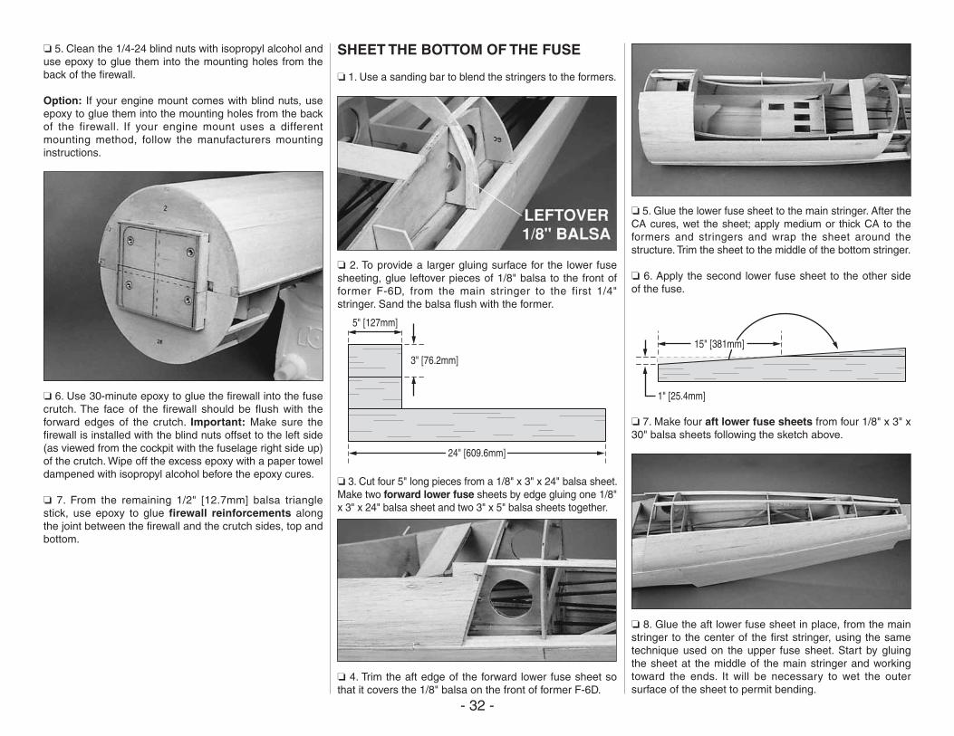
- 32 -
❏ 5. Clean the 1/4-24 blind nuts with isopropyl alcohol and use epoxy to glue them into the mounting holes from the back of the firewall.
Option: If your engine mount comes with blind nuts, use epoxy to glue them into the mounting holes from the back of the firewall. If your engine mount uses a different mounting method, follow the manufacturers mounting instructions.
❏ 6. Use 30-minute epoxy to glue the firewall into the fuse crutch. The face of the firewall should be flush with the forward edges of the crutch. Important: Make sure the firewall is installed with the blind nuts offset to the left side (as viewed from the cockpit with the fuselage right side up) of the crutch. Wipe off the excess epoxy with a paper towel dampened with isopropyl alcohol before the epoxy cures.
❏ 7. From the remaining 1/2" [12.7mm] balsa triangle stick, use epoxy to glue firewall reinforcements along the joint between the firewall and the crutch sides, top and bottom.
SHEET THE BOTTOM OF THE FUSE
❏ 1. Use a sanding bar to blend the stringers to the formers.
❏ 2. To provide a larger gluing surface for the lower fuse sheeting, glue leftover pieces of 1/8" balsa to the front of former F-6D, from the main stringer to the first 1/4" stringer. Sand the balsa flush with the former.
5" [127mm]
24" [609.6mm]
3" [76.2mm]
❏ 3. Cut four 5" long pieces from a 1/8" x 3" x 24" balsa sheet. Make two forward lower fuse sheets by edge gluing one 1/8" x 3" x 24" balsa sheet and two 3" x 5" balsa sheets together.
❏ 4. Trim the aft edge of the forward lower fuse sheet so that it covers the 1/8" balsa on the front of former F-6D.
❏ 5. Glue the lower fuse sheet to the main stringer. After the CA cures, wet the sheet; apply medium or thick CA to the formers and stringers and wrap the sheet around the structure. Trim the sheet to the middle of the bottom stringer.
❏ 6. Apply the second lower fuse sheet to the other side of the fuse.
1" [25.4mm]
15" [381mm]
❏ 7. Make four aft lower fuse sheets from four 1/8" x 3" x 30" balsa sheets following the sketch above.
❏ 8. Glue the aft lower fuse sheet in place, from the main stringer to the center of the first stringer, using the same technique used on the upper fuse sheet. Start by gluing the sheet at the middle of the main stringer and working toward the ends. It will be necessary to wet the outer surface of the sheet to permit bending.
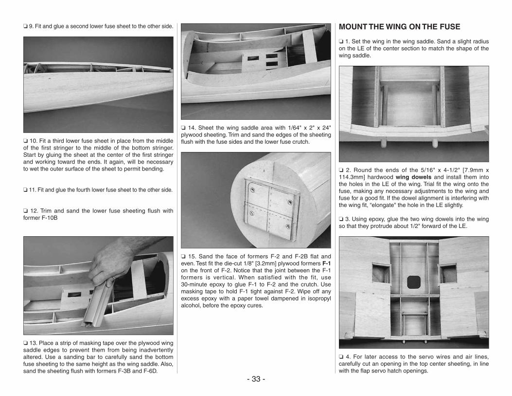
- 33 -
❏ 9. Fit and glue a second lower fuse sheet to the other side.
❏ 10. Fit a third lower fuse sheet in place from the middle of the first stringer to the middle of the bottom stringer. Start by gluing the sheet at the center of the first stringer and working toward the ends. It again, will be necessary to wet the outer surface of the sheet to permit bending.
❏ 11. Fit and glue the fourth lower fuse sheet to the other side.
❏ 12. Trim and sand the lower fuse sheeting flush with former F-10B
❏ 13. Place a strip of masking tape over the plywood wing saddle edges to prevent them from being inadvertently altered. Use a sanding bar to carefully sand the bottom fuse sheeting to the same height as the wing saddle. Also, sand the sheeting flush with formers F-3B and F-6D.
❏ 14. Sheet the wing saddle area with 1/64" x 2" x 24" plywood sheeting. Trim and sand the edges of the sheeting flush with the fuse sides and the lower fuse crutch.
❏ 15. Sand the face of formers F-2 and F-2B flat and even. Test fit the die-cut 1/8" [3.2mm] plywood formers F-1 on the front of F-2. Notice that the joint between the F-1 formers is vertical. When satisfied with the fit, use 30-minute epoxy to glue F-1 to F-2 and the crutch. Use masking tape to hold F-1 tight against F-2. Wipe off any excess epoxy with a paper towel dampened in isopropyl alcohol, before the epoxy cures.
MOUNT THE WING ON THE FUSE
❏ 1. Set the wing in the wing saddle. Sand a slight radius on the LE of the center section to match the shape of the wing saddle.
❏ 2. Round the ends of the 5/16" x 4-1/2" [7.9mm x 114.3mm] hardwood wing dowels and install them into the holes in the LE of the wing. Trial fit the wing onto the fuse, making any necessary adjustments to the wing and fuse for a good fit. If the dowel alignment is interfering with the wing fit, “elongate" the hole in the LE slightly.
❏ 3. Using epoxy, glue the two wing dowels into the wing so that they protrude about 1/2" forward of the LE.
❏ 4. For later access to the servo wires and air lines, carefully cut an opening in the top center sheeting, in line with the flap servo hatch openings.
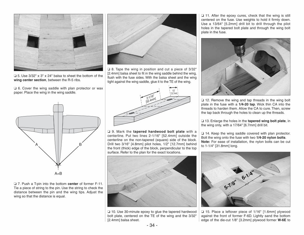
- 34 -
❏ 5. Use 3/32" x 3" x 24" balsa to sheet the bottom of the wing center section, between the R-5 ribs.
❏ 6. Cover the wing saddle with plan protector or wax paper. Place the wing in the wing saddle.
B
A=B
A
❏ 7. Push a T-pin into the bottom center of former F-11. Tie a piece of string to the pin. Use the string to check the distance between the pin and the wing tips. Adjust the wing so that the distance is equal.
❏ 8. Tape the wing in position and cut a piece of 3/32" [2.4mm] balsa sheet to fit in the wing saddle behind the wing, flush with the fuse sides. With the balsa sheet and the wing tight against the wing saddle, glue it to the TE of the wing.
❏ 9. Mark the tapered hardwood bolt plate with a centerline. Put two lines 2-1/16" [52.4mm] outside the centerline on the non-tapered (square) side of the block. Drill two 3/16" [4.8mm] pilot holes, 1/2" [12.7mm] behind the front (thick) edge of the block, perpendicular to the top surface. Refer to the plan for the exact locations.
❏ 10. Use 30-minute epoxy to glue the tapered hardwood bolt plate, centered on the TE of the wing and the 3/32" [2.4mm] balsa sheet.
❏ 11. After the epoxy cures, check that the wing is still centered on the fuse. Use weights to hold it firmly down. Use a 13/64" [5.2mm] drill bit to drill through the pilot holes in the tapered bolt plate and through the wing bolt plate in the fuse.
❏ 12. Remove the wing and tap threads in the wing bolt plate in the fuse with a 1/4-20 tap. Wick thin CA into the threads to harden them. Allow the CA to cure. Then, screw the tap back through the holes to clean up the threads.
❏ 13. Enlarge the holes in the tapered wing bolt plate, in the wing only, with a 17/64" [6.7mm] drill bit.
❏ 14. Keep the wing saddle covered with plan protector. Bolt the wing onto the fuse with two 1/4-20 nylon bolts. Note: For ease of installation, the nylon bolts can be cut to 1-1/4" [31.8mm] long.
❏ 15. Place a leftover piece of 1/16" [1.6mm] plywood against the front of former F-6D. Lightly sand the bottom edge of the die-cut 1/8" [3.2mm] plywood former W-6E to
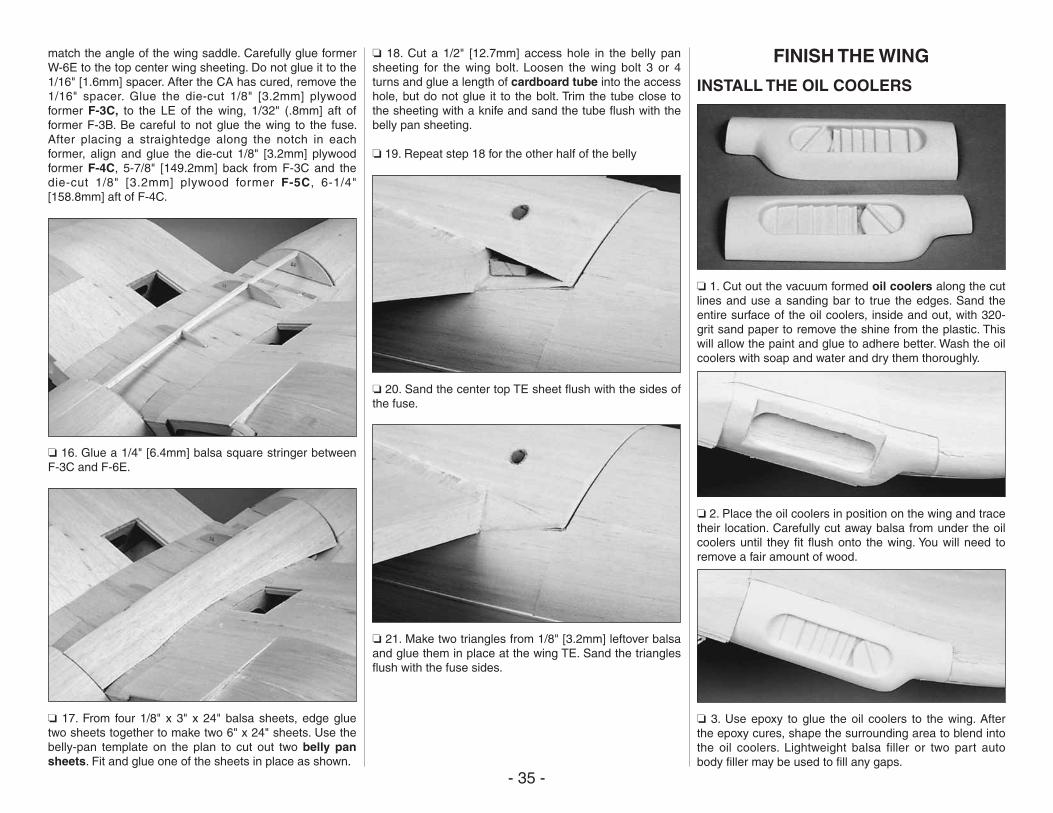
- 35 -
match the angle of the wing saddle. Carefully glue former W-6E to the top center wing sheeting. Do not glue it to the 1/16" [1.6mm] spacer. After the CA has cured, remove the 1/16" spacer. Glue the die-cut 1/8" [3.2mm] plywood former F-3C, to the LE of the wing, 1/32" (.8mm] aft of former F-3B. Be careful to not glue the wing to the fuse. After placing a straightedge along the notch in each former, align and glue the die-cut 1/8" [3.2mm] plywood former F-4C, 5-7/8" [149.2mm] back from F-3C and the die-cut 1/8" [3.2mm] plywood former F-5C, 6-1/4" [158.8mm] aft of F-4C.
❏ 16. Glue a 1/4" [6.4mm] balsa square stringer between F-3C and F-6E.
❏ 17. From four 1/8" x 3" x 24" balsa sheets, edge glue two sheets together to make two 6" x 24" sheets. Use the belly-pan template on the plan to cut out two belly pan sheets. Fit and glue one of the sheets in place as shown.
❏ 18. Cut a 1/2" [12.7mm] access hole in the belly pan sheeting for the wing bolt. Loosen the wing bolt 3 or 4 turns and glue a length of cardboard tube into the access hole, but do not glue it to the bolt. Trim the tube close to the sheeting with a knife and sand the tube flush with the belly pan sheeting.
❏ 19. Repeat step 18 for the other half of the belly
❏ 20. Sand the center top TE sheet flush with the sides of the fuse.
❏ 21. Make two triangles from 1/8" [3.2mm] leftover balsa and glue them in place at the wing TE. Sand the triangles flush with the fuse sides.
FINISH THE WING
INSTALL THE OIL COOLERS
❏ 1. Cut out the vacuum formed oil coolers along the cut lines and use a sanding bar to true the edges. Sand the entire surface of the oil coolers, inside and out, with 320-grit sand paper to remove the shine from the plastic. This will allow the paint and glue to adhere better. Wash the oil coolers with soap and water and dry them thoroughly.
❏ 2. Place the oil coolers in position on the wing and trace their location. Carefully cut away balsa from under the oil coolers until they fit flush onto the wing. You will need to remove a fair amount of wood.
❏ 3. Use epoxy to glue the oil coolers to the wing. After the epoxy cures, shape the surrounding area to blend into the oil coolers. Lightweight balsa filler or two part auto body filler may be used to fill any gaps.
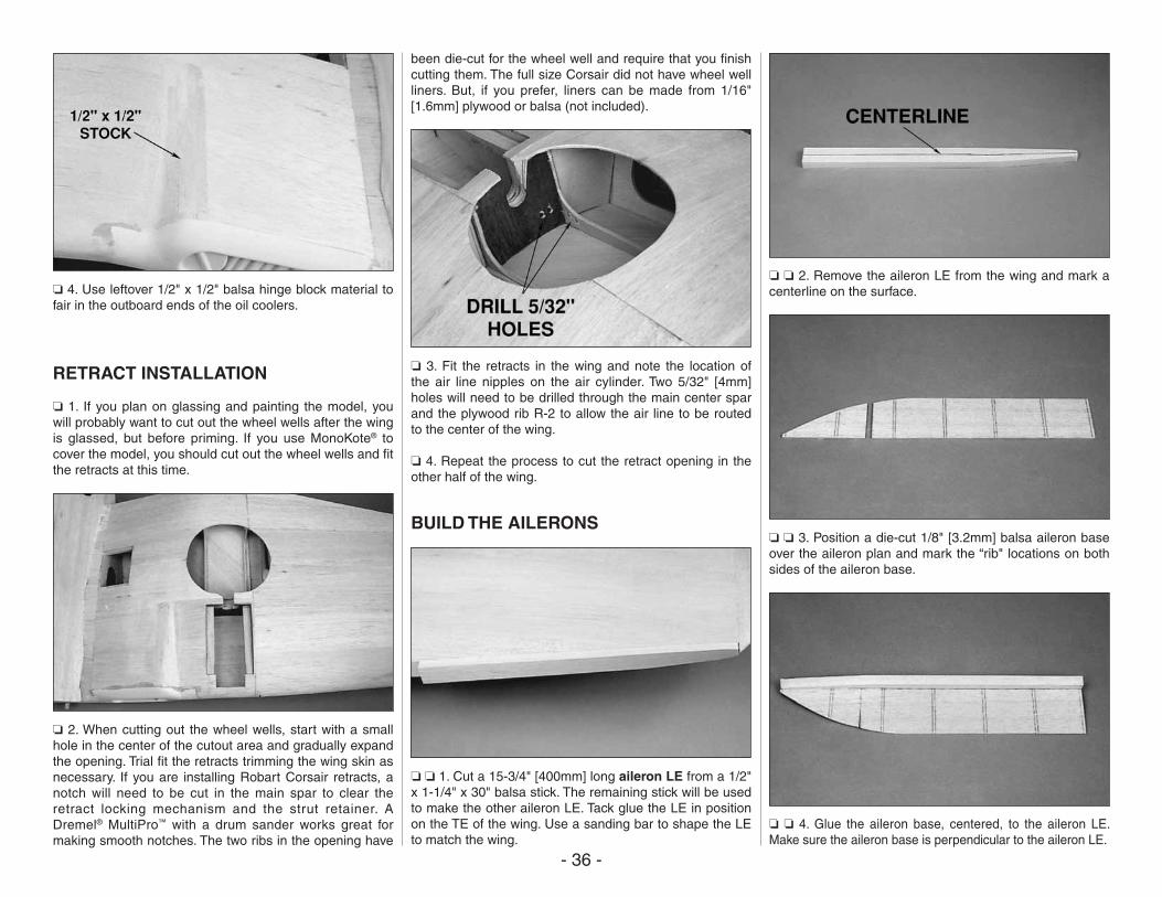
- 36 -
❏ 4. Use leftover 1/2" x 1/2" balsa hinge block material to fair in the outboard ends of the oil coolers.
RETRACT INSTALLATION
❏ 1. If you plan on glassing and painting the model, you will probably want to cut out the wheel wells after the wing is glassed, but before priming. If you use MonoKote® to cover the model, you should cut out the wheel wells and fit the retracts at this time.
❏ 2. When cutting out the wheel wells, start with a small hole in the center of the cutout area and gradually expand the opening. Trial fit the retracts trimming the wing skin as necessary. If you are installing Robart Corsair retracts, a notch will need to be cut in the main spar to clear the retract locking mechanism and the strut retainer. A Dremel® MultiPro™ with a drum sander works great for making smooth notches. The two ribs in the opening have
been die-cut for the wheel well and require that you finish cutting them. The full size Corsair did not have wheel well liners. But, if you prefer, liners can be made from 1/16" [1.6mm] plywood or balsa (not included).
❏ 3. Fit the retracts in the wing and note the location of the air line nipples on the air cylinder. Two 5/32" [4mm] holes will need to be drilled through the main center spar and the plywood rib R-2 to allow the air line to be routed to the center of the wing.
❏ 4. Repeat the process to cut the retract opening in the other half of the wing.
BUILD THE AILERONS
❏ ❏ 1. Cut a 15-3/4" [400mm] long aileron LE from a 1/2" x 1-1/4" x 30" balsa stick. The remaining stick will be used to make the other aileron LE. Tack glue the LE in position on the TE of the wing. Use a sanding bar to shape the LE to match the wing.
❏ ❏ 2. Remove the aileron LE from the wing and mark a centerline on the surface.
❏ ❏ 3. Position a die-cut 1/8" [3.2mm] balsa aileron base over the aileron plan and mark the “rib" locations on both sides of the aileron base.
❏ ❏ 4. Glue the aileron base, centered, to the aileron LE. Make sure the aileron base is perpendicular to the aileron LE.
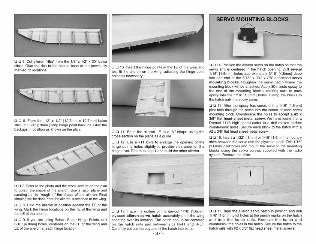
- 37 -
❏ ❏ 5. Cut aileron “ribs” from the 1/8" x 1/2" x 30" balsa sticks. Glue the ribs to the aileron base at the previously marked rib locations.
❏ ❏ 6. From the 1/2" x 1/2" [12.7mm x 12.7mm] balsa stick, cut 3/4" [19mm ) long hinge point backups. Glue the backups in position as shown on the plan.
❏ ❏ 7. Refer to the photo and the cross-section on the plan to obtain the shape of the aileron. Use a razor plane and sanding bar to “rough in” the shape of the aileron. Final shaping will be done after the aileron is attached to the wing.
❏ ❏ 8. Hold the aileron in position against the TE of the wing. Mark the hinge locations on the TE of the wing and the LE of the aileron.
❏ ❏ 9. If you are using Robart Super Hinge Points, drill 3/16" [4.8mm] holes, centered on the TE of the wing and LE of the aileron at each hinge location.
❏ ❏ 10. Insert the hinge points in the TE of the wing and test fit the aileron on the wing, adjusting the hinge point holes as necessary.
❏ ❏ 11. Sand the aileron LE to a “V” shape using the cross-section on the plans as a guide.
❏ ❏ 12. Use a #11 knife to enlarge the opening of the hinge points holes slightly to provide clearance for the hinge pivot. Return to step 1 and build the other aileron.
❏ ❏ 13. Trace the outline of the die-cut 1/16" [1.6mm] plywood aileron servo hatch accurately onto the wing sheeting over its location. The hatch should be centered on the hatch rails and between ribs R-4T and R-5T. Carefully cut out the bay and fit the hatch into place.
❏ ❏ 14. Position the aileron servo on the hatch so that the servo arm is centered in the hatch opening. Drill several 1/16" [1.6mm] holes approximately 3/16" [4.8mm] deep into one end of the 5/16" x 3/4" x 7/8" basswood servo mounting blocks. Roughen the servo hatch where the mounting block will be attached. Apply 30-minute epoxy to the end of the mounting blocks, making sure to pack epoxy into the 1/16" [1.6mm] holes. Clamp the blocks to the hatch until the epoxy cures.
❏ ❏ 15. After the epoxy has cured, drill a 1/16" [1.6mm] pilot hole through the hatch into the center of each servo mounting block. Countersink the holes to accept a #2 x 3/8" flat head sheet metal screw. We have found that a Dremel #178 high speed cutter in a drill makes perfect countersunk holes. Secure each block to the hatch with a #2 x 3/8" flat head sheet metal screw.
❏ ❏ 16. Insert a 1/32" (.8mm] or 1/16" [1.6mm] temporary shim between the servo and the plywood hatch. Drill 1/16" [1.6mm] pilot holes and mount the servo to the mounting blocks using the servo screws supplied with the radio system. Remove the shim.
❏ ❏ 17. Tape the aileron servo hatch in position and drill 1/16" [1.6mm] pilot holes at the punch marks on the hatch and into the hatch rails. Remove the hatch and countersink the holes in the hatch. Secure the hatch to the hatch rails with #2 x 3/8" flat head sheet metal screws.
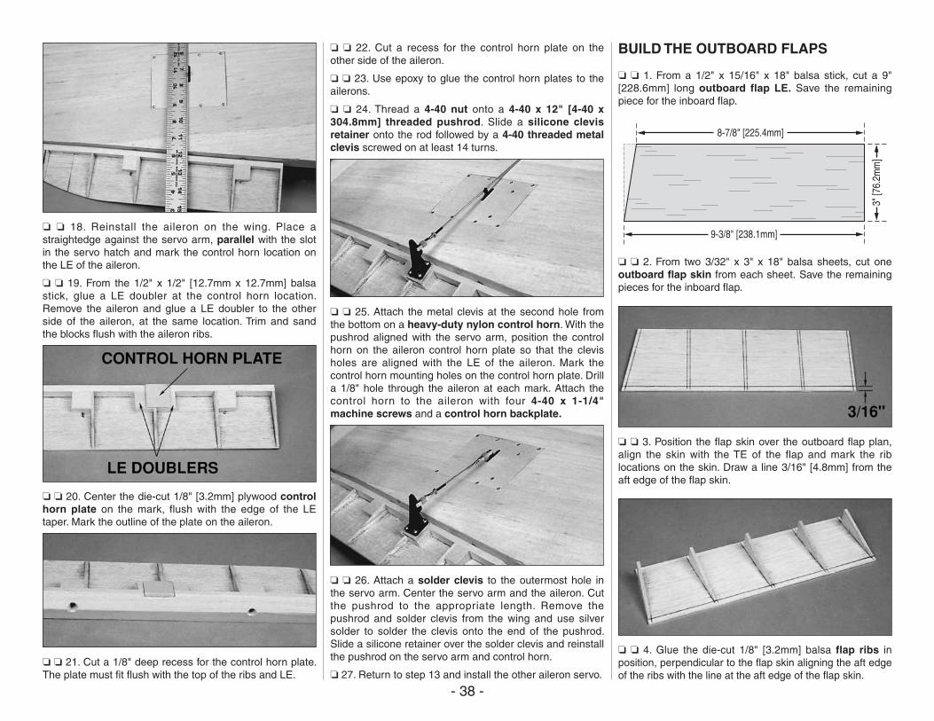
- 38 -
❏ ❏ 18. Reinstall the aileron on the wing. Place a straightedge against the servo arm, parallel with the slot in the servo hatch and mark the control horn location on the LE of the aileron.
❏ ❏ 19. From the 1/2" x 1/2" [12.7mm x 12.7mm] balsa stick, glue a LE doubler at the control horn location. Remove the aileron and glue a LE doubler to the other side of the aileron, at the same location. Trim and sand the blocks flush with the aileron ribs.
❏ ❏ 20. Center the die-cut 1/8" [3.2mm] plywood control horn plate on the mark, flush with the edge of the LE taper. Mark the outline of the plate on the aileron.
❏ ❏ 21. Cut a 1/8" deep recess for the control horn plate. The plate must fit flush with the top of the ribs and LE.
❏ ❏ 22. Cut a recess for the control horn plate on the other side of the aileron.
❏ ❏ 23. Use epoxy to glue the control horn plates to the ailerons.
❏ ❏ 24. Thread a 4-40 nut onto a 4-40 x 12" [4-40 x 304.8mm] threaded pushrod. Slide a silicone clevis retainer onto the rod followed by a 4-40 threaded metal clevis screwed on at least 14 turns.
❏ ❏ 25. Attach the metal clevis at the second hole from the bottom on a heavy-duty nylon control horn. With the pushrod aligned with the servo arm, position the control horn on the aileron control horn plate so that the clevis holes are aligned with the LE of the aileron. Mark the control horn mounting holes on the control horn plate. Drill a 1/8" hole through the aileron at each mark. Attach the control horn to the aileron with four 4-40 x 1-1/4" machine screws and a control horn backplate.
❏ ❏ 26. Attach a solder clevis to the outermost hole in the servo arm. Center the servo arm and the aileron. Cut the pushrod to the appropriate length. Remove the pushrod and solder clevis from the wing and use silver solder to solder the clevis onto the end of the pushrod. Slide a silicone retainer over the solder clevis and reinstall the pushrod on the servo arm and control horn.
❏ 27. Return to step 13 and install the other aileron servo.
BUILD THE OUTBOARD FLAPS
❏ ❏ 1. From a 1/2" x 15/16" x 18" balsa stick, cut a 9" [228.6mm] long outboard flap LE. Save the remaining piece for the inboard flap.
8-7/8" [225.4mm]
3" [7
6.2m
m]
9-3/8" [238.1mm]
❏ ❏ 2. From two 3/32" x 3" x 18" balsa sheets, cut one outboard flap skin from each sheet. Save the remaining pieces for the inboard flap.
❏ ❏ 3. Position the flap skin over the outboard flap plan, align the skin with the TE of the flap and mark the rib locations on the skin. Draw a line 3/16" [4.8mm] from the aft edge of the flap skin.
❏ ❏ 4. Glue the die-cut 1/8" [3.2mm] balsa flap ribs in position, perpendicular to the flap skin aligning the aft edge of the ribs with the line at the aft edge of the flap skin.
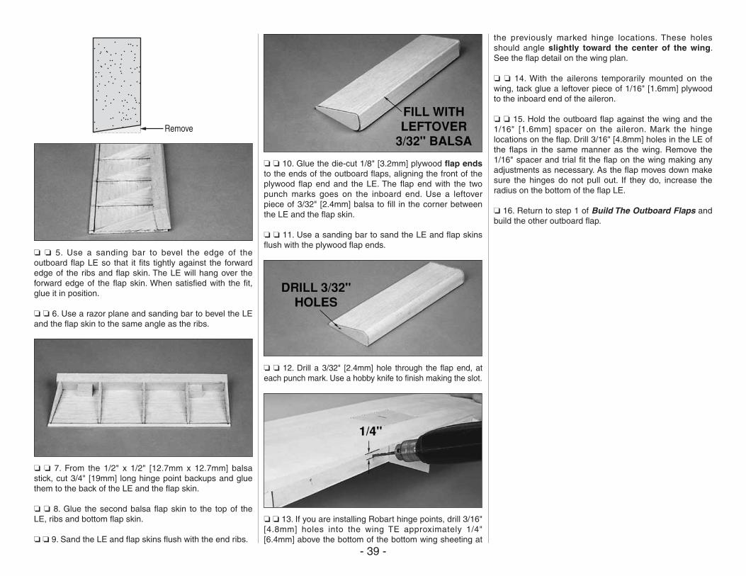
- 39 -
Remove
❏ ❏ 5. Use a sanding bar to bevel the edge of the outboard flap LE so that it fits tightly against the forward edge of the ribs and flap skin. The LE will hang over the forward edge of the flap skin. When satisfied with the fit, glue it in position.
❏ ❏ 6. Use a razor plane and sanding bar to bevel the LE and the flap skin to the same angle as the ribs.
❏ ❏ 7. From the 1/2" x 1/2" [12.7mm x 12.7mm] balsa stick, cut 3/4" [19mm] long hinge point backups and glue them to the back of the LE and the flap skin.
❏ ❏ 8. Glue the second balsa flap skin to the top of the LE, ribs and bottom flap skin.
❏ ❏ 9. Sand the LE and flap skins flush with the end ribs.
❏ ❏ 10. Glue the die-cut 1/8" [3.2mm] plywood flap ends to the ends of the outboard flaps, aligning the front of the plywood flap end and the LE. The flap end with the two punch marks goes on the inboard end. Use a leftover piece of 3/32" [2.4mm] balsa to fill in the corner between the LE and the flap skin.
❏ ❏ 11. Use a sanding bar to sand the LE and flap skins flush with the plywood flap ends.
❏ ❏ 12. Drill a 3/32" [2.4mm] hole through the flap end, at each punch mark. Use a hobby knife to finish making the slot.
❏ ❏ 13. If you are installing Robart hinge points, drill 3/16" [4.8mm] holes into the wing TE approximately 1/4" [6.4mm] above the bottom of the bottom wing sheeting at
the previously marked hinge locations. These holes should angle slightly toward the center of the wing. See the flap detail on the wing plan.
❏ ❏ 14. With the ailerons temporarily mounted on the wing, tack glue a leftover piece of 1/16" [1.6mm] plywood to the inboard end of the aileron.
❏ ❏ 15. Hold the outboard flap against the wing and the 1/16" [1.6mm] spacer on the aileron. Mark the hinge locations on the flap. Drill 3/16" [4.8mm] holes in the LE of the flaps in the same manner as the wing. Remove the 1/16" spacer and trial fit the flap on the wing making any adjustments as necessary. As the flap moves down make sure the hinges do not pull out. If they do, increase the radius on the bottom of the flap LE.
❏ 16. Return to step 1 of Build The Outboard Flaps and build the other outboard flap.
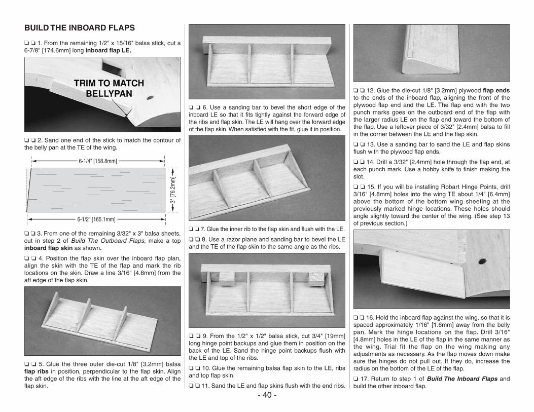
- 40 -
BUILD THE INBOARD FLAPS
❏ ❏ 1. From the remaining 1/2" x 15/16" balsa stick, cut a 6-7/8" [174.6mm] long inboard flap LE.
❏ ❏ 2. Sand one end of the stick to match the contour of the belly pan at the TE of the wing.
6-1/4" [158.8mm]
3" [7
6.2m
m]
6-1/2" [165.1mm]
❏ ❏ 3. From one of the remaining 3/32" x 3" balsa sheets, cut in step 2 of Build The Outboard Flaps, make a top inboard flap skin as shown.
❏ ❏ 4. Position the flap skin over the inboard flap plan, align the skin with the TE of the flap and mark the rib locations on the skin. Draw a line 3/16" [4.8mm] from the aft edge of the flap skin.
❏ ❏ 5. Glue the three outer die-cut 1/8" [3.2mm] balsa flap ribs in position, perpendicular to the flap skin. Align the aft edge of the ribs with the line at the aft edge of the flap skin.
❏ ❏ 6. Use a sanding bar to bevel the short edge of the inboard LE so that it fits tightly against the forward edge of the ribs and flap skin. The LE will hang over the forward edge of the flap skin. When satisfied with the fit, glue it in position.
❏ ❏ 7. Glue the inner rib to the flap skin and flush with the LE.
❏ ❏ 8. Use a razor plane and sanding bar to bevel the LE and the TE of the flap skin to the same angle as the ribs.
❏ ❏ 9. From the 1/2" x 1/2" balsa stick, cut 3/4" [19mm] long hinge point backups and glue them in position on the back of the LE. Sand the hinge point backups flush with the LE and top of the ribs.
❏ ❏ 10. Glue the remaining balsa flap skin to the LE, ribs and top flap skin.
❏ ❏ 11. Sand the LE and flap skins flush with the end ribs.
❏ ❏ 12. Glue the die-cut 1/8" [3.2mm] plywood flap ends to the ends of the inboard flap, aligning the front of the plywood flap end and the LE. The flap end with the two punch marks goes on the outboard end of the flap with the larger radius LE on the flap end toward the bottom of the flap. Use a leftover piece of 3/32" [2.4mm] balsa to fill in the corner between the LE and the flap skin.
❏ ❏ 13. Use a sanding bar to sand the LE and flap skins flush with the plywood flap ends.
❏ ❏ 14. Drill a 3/32" [2.4mm] hole through the flap end, at each punch mark. Use a hobby knife to finish making the slot.
❏ ❏ 15. If you will be installing Robart Hinge Points, drill 3/16" [4.8mm] holes into the wing TE about 1/4" [6.4mm] above the bottom of the bottom wing sheeting at the previously marked hinge locations. These holes should angle slightly toward the center of the wing. (See step 13 of previous section.)
❏ ❏ 16. Hold the inboard flap against the wing, so that it is spaced approximately 1/16" [1.6mm] away from the belly pan. Mark the hinge locations on the flap. Drill 3/16" [4.8mm] holes in the LE of the flap in the same manner as the wing. Trial fit the flap on the wing making any adjustments as necessary. As the flap moves down make sure the hinges do not pull out. If they do, increase the radius on the bottom of the LE of the flap.
❏ 17. Return to step 1 of Build The Inboard Flaps and build the other inboard flap.
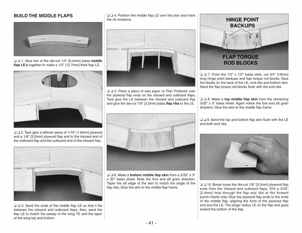
- 41 -
BUILD THE MIDDLE FLAPS
❏ ❏ 1. Glue two of the die-cut 1/4" [6.4mm] balsa middle flap LE’s together to make a 1/2" [12.7mm] thick flap LE.
❏ ❏ 2. Tack glue a leftover piece of 1/16" [1.6mm] plywood and a 1/8" [3.2mm] plywood flap end to the inboard end of the outboard flap and the outboard end of the inboard flap.
❏ ❏ 3. Sand the ends of the middle flap LE so that it fits between the inboard and outboard flaps. Also, sand the flap LE to match the sweep of the wing TE and the taper of the wing top and bottom.
❏ ❏ 4. Position the middle flap LE over the plan and mark the rib locations.
❏ ❏ 5. Place a piece of wax paper or Plan Protector over the plywood flap ends on the inboard and outboard flaps. Tack glue the LE between the inboard and outboard flap and glue the die-cut 1/8" [3.2mm] balsa flap ribs to the LE.
❏ ❏ 6. Make a bottom middle flap skin from a 3/32" x 3" x 30" balsa sheet. Note the fore and aft grain direction. Taper the aft edge of the skin to match the angle of the flap ribs. Glue the skin to the middle flap frame.
❏ ❏ 7. From the 1/2" x 1/2" balsa stick, cut 3/4" [19mm] long hinge point backups and flap torque rod blocks. Glue the blocks on the back of the LE, end ribs and bottom skin. Sand the flap torque rod blocks flush with the end ribs.
❏ ❏ 8. Make a top middle flap skin from the remaining 3/32" x 3" balsa sheet. Again notice the fore and aft grain direction. Glue the skin to the middle flap frame.
❏ ❏ 9. Sand the top and bottom flap skin flush with the LE and both end ribs.
❏ ❏ 10. Break loose the die-cut 1/8" [3.2mm] plywood flap ends from the inboard and outboard flaps. Drill a 3/32" [2.4mm] hole through the flap end ribs at the forward punch marks only. Glue the plywood flap ends to the ends of the middle flap, aligning the front of the plywood flap end and the LE. The larger radius LE on the flap end goes toward the bottom of the flap.
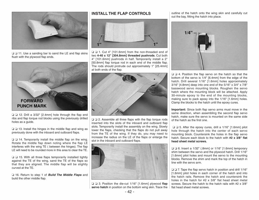
- 42 -
❏ ❏ 11. Use a sanding bar to sand the LE and flap skins flush with the plywood flap ends.
❏ ❏ 12. Drill a 3/32" [2.4mm] hole through the flap end ribs and flap torque rod blocks using the previously drilled holes as a guide.
❏ ❏ 13. Install the hinges in the middle flap and wing as previously done with the inboard and outboard flaps.
❏ ❏ 14. Temporarily install the middle flap on the wing. Rotate the middle flap down noting where the flap LE interferes with the wing TE ( between the hinges). The flap LE will need to be rounded more in this area to clear the TE.
❏ ❏ 15. With all three flaps temporarily installed tightly against the TE of the wing, sand the TE of the flaps so that they are aligned. The middle flap will be slightly curved at the TE.
❏ 16. Return to step 1 of Build The Middle Flaps and build the other middle flap.
INSTALL THE FLAP CONTROLS
❏ ❏ 1. Cut 4" [101.6mm] from the non-threaded end of two 4-40 x 12" [304.8mm] threaded pushrods. Cut both 4" [101.6mm] pushrods in half. Temporarily install a 2" [50.8mm] flap torque rod in each end of the middle flap. The rods should protrude out approximately 1" [25.4mm] at both ends of the flap.
❏ ❏ 2. Assemble all three flaps with the flap torque rods inserted into the slots of the inboard and outboard flap slots. Temporarily install the assembly on the wing. Slowly lower the flaps, checking that the flaps do not pull away from the TE of the wing. If they do, you may need to increase the radius on the LE of the flaps or enlarge the slot in the inboard and outboard flaps.
❏ ❏ 3. Position the die-cut 1/16" [1.6mm] plywood flap servo hatch in position on the bottom wing skin. Trace the
outline of the hatch onto the wing skin and carefully cut out the bay, fitting the hatch into place.
❏ ❏ 4. Position the flap servo on the hatch so that the bottom of the servo is 1/4" [6.4mm] from the edge of the hatch. Drill several 1/16" [1.6mm] holes approximately 3/16" [4.8mm] deep into one end of the 5/16" x 3/4" x 7/8" basswood servo mounting blocks. Roughen the servo hatch where the mounting block will be attached. Apply 30-minute epoxy to the end of the mounting blocks, making sure to pack epoxy into the 1/16" [1.6mm] holes. Clamp the blocks to the hatch until the epoxy cures.
Important: Since both flap servo arms must move in the same direction, when assembling the second flap servo hatch, make sure the servo is mounted on the same side of the hatch as the first one.
❏ ❏ 5. After the epoxy cures, drill a 1/16" [1.6mm] pilot hole through the hatch into the center of each servo mounting block. Countersink the holes in the flap servo hatch. Secure each block to the hatch with #2 x 3/8" flat head sheet metal screws.
❏ ❏ 6. Insert a 1/32" (.8mm] or 1/16" [1.6mm] temporary shim between the servo and the plywood hatch. Drill 1/16" [1.6mm] pilot holes and mount the servo to the mounting blocks. Remove the shim and mark the top of the hatch in line with the servo arm.
❏ ❏ 7. Tape the flap servo hatch in position and drill 1/16" [1.6mm] pilot holes in each corner of the hatch and into the hatch rails. Remove the hatch and countersink the holes in the hatch for #2 x 3/8" flat head sheet metal screws. Secure the hatch to the hatch rails with #2 x 3/8" flat head sheet metal screws.
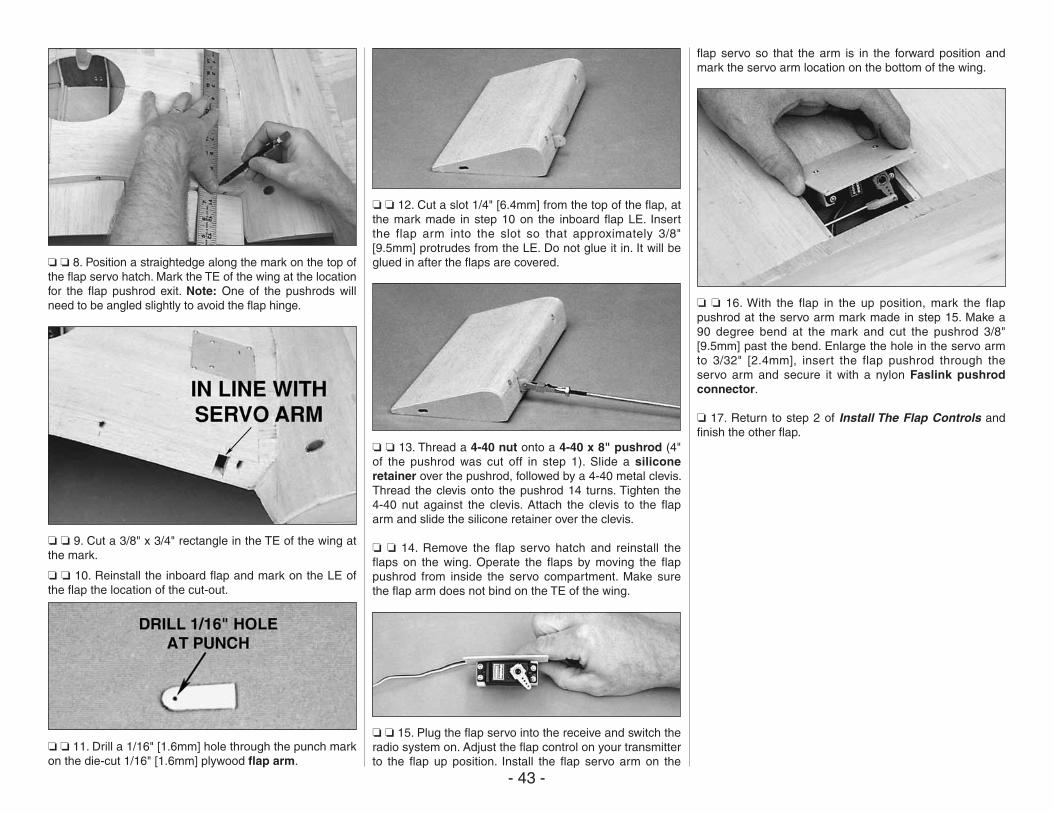
- 43 -
❏ ❏ 8. Position a straightedge along the mark on the top of the flap servo hatch. Mark the TE of the wing at the location for the flap pushrod exit. Note: One of the pushrods will need to be angled slightly to avoid the flap hinge.
❏ ❏ 9. Cut a 3/8" x 3/4" rectangle in the TE of the wing at the mark.
❏ ❏ 10. Reinstall the inboard flap and mark on the LE of the flap the location of the cut-out.
❏ ❏ 11. Drill a 1/16" [1.6mm] hole through the punch mark on the die-cut 1/16" [1.6mm] plywood flap arm.
❏ ❏ 12. Cut a slot 1/4" [6.4mm] from the top of the flap, at the mark made in step 10 on the inboard flap LE. Insert the flap arm into the slot so that approximately 3/8" [9.5mm] protrudes from the LE. Do not glue it in. It will be glued in after the flaps are covered.
❏ ❏ 13. Thread a 4-40 nut onto a 4-40 x 8" pushrod (4" of the pushrod was cut off in step 1). Slide a silicone retainer over the pushrod, followed by a 4-40 metal clevis. Thread the clevis onto the pushrod 14 turns. Tighten the 4-40 nut against the clevis. Attach the clevis to the flap arm and slide the silicone retainer over the clevis.
❏ ❏ 14. Remove the flap servo hatch and reinstall the flaps on the wing. Operate the flaps by moving the flap pushrod from inside the servo compartment. Make sure the flap arm does not bind on the TE of the wing.
❏ ❏ 15. Plug the flap servo into the receive and switch the radio system on. Adjust the flap control on your transmitter to the flap up position. Install the flap servo arm on the
flap servo so that the arm is in the forward position and mark the servo arm location on the bottom of the wing.
❏ ❏ 16. With the flap in the up position, mark the flap pushrod at the servo arm mark made in step 15. Make a 90 degree bend at the mark and cut the pushrod 3/8" [9.5mm] past the bend. Enlarge the hole in the servo arm to 3/32" [2.4mm], insert the flap pushrod through the servo arm and secure it with a nylon Faslink pushrod connector.
❏ 17. Return to step 2 of Install The Flap Controls and finish the other flap.
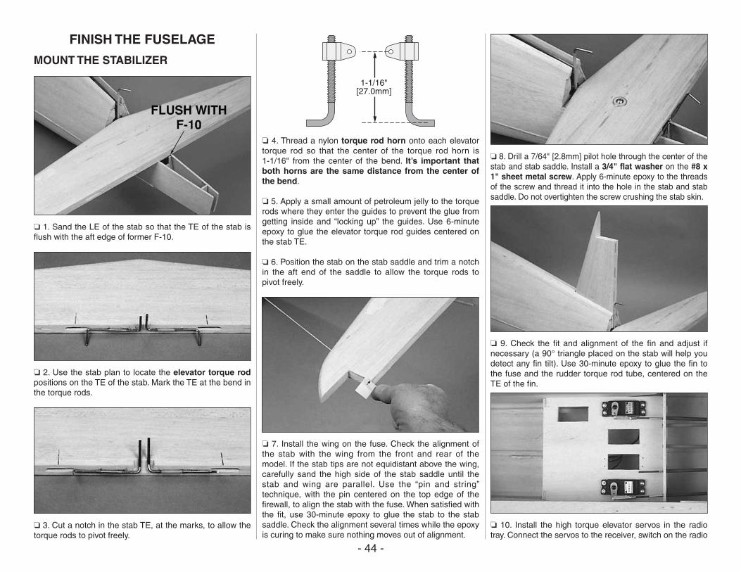
- 44 -
FINISH THE FUSELAGE
MOUNT THE STABILIZER
❏ 1. Sand the LE of the stab so that the TE of the stab is flush with the aft edge of former F-10.
❏ 2. Use the stab plan to locate the elevator torque rod positions on the TE of the stab. Mark the TE at the bend in the torque rods.
❏ 3. Cut a notch in the stab TE, at the marks, to allow the torque rods to pivot freely.
1-1/16"[27.0mm]
❏ 4. Thread a nylon torque rod horn onto each elevator torque rod so that the center of the torque rod horn is 1-1/16" from the center of the bend. It’s important that both horns are the same distance from the center of the bend.
❏ 5. Apply a small amount of petroleum jelly to the torque rods where they enter the guides to prevent the glue from getting inside and “locking up” the guides. Use 6-minute epoxy to glue the elevator torque rod guides centered on the stab TE.
❏ 6. Position the stab on the stab saddle and trim a notch in the aft end of the saddle to allow the torque rods to pivot freely.
❏ 7. Install the wing on the fuse. Check the alignment of the stab with the wing from the front and rear of the model. If the stab tips are not equidistant above the wing, carefully sand the high side of the stab saddle until the stab and wing are parallel. Use the “pin and string” technique, with the pin centered on the top edge of the firewall, to align the stab with the fuse. When satisfied with the fit, use 30-minute epoxy to glue the stab to the stab saddle. Check the alignment several times while the epoxy is curing to make sure nothing moves out of alignment.
❏ 8. Drill a 7/64" [2.8mm] pilot hole through the center of the stab and stab saddle. Install a 3/4" flat washer on the #8 x 1" sheet metal screw. Apply 6-minute epoxy to the threads of the screw and thread it into the hole in the stab and stab saddle. Do not overtighten the screw crushing the stab skin.
❏ 9. Check the fit and alignment of the fin and adjust if necessary (a 90° triangle placed on the stab will help you detect any fin tilt). Use 30-minute epoxy to glue the fin to the fuse and the rudder torque rod tube, centered on the TE of the fin.
❏ 10. Install the high torque elevator servos in the radio tray. Connect the servos to the receiver, switch on the radio
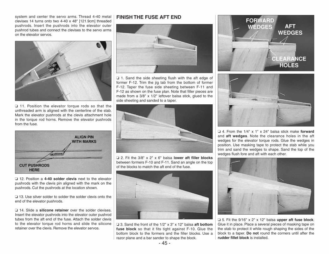
- 45 -
system and center the servo arms. Thread 4-40 metal clevises 14 turns onto two 4-40 x 48" [121.9cm] threaded pushrods. Insert the pushrods into the elevator outer pushrod tubes and connect the clevises to the servo arms on the elevator servos.
❏ 11. Position the elevator torque rods so that the unthreaded arm is aligned with the centerline of the stab. Mark the elevator pushrods at the clevis attachment hole in the torque rod horns. Remove the elevator pushrods from the fuse.
❏ 12. Position a 4-40 solder clevis next to the elevator pushrods with the clevis pin aligned with the mark on the pushrods. Cut the pushrods at the location shown.
❏ 13. Use silver solder to solder the solder clevis onto the end of the elevator pushrods.
❏ 14. Slide a silicone retainer over the solder clevises. Insert the elevator pushrods into the elevator outer pushrod tubes from the aft end of the fuse. Attach the solder clevis to the elevator torque rod horns and slide the silicone retainer over the clevis. Remove the elevator servos.
FINISH THE FUSE AFT END
❏ 1. Sand the side sheeting flush with the aft edge of former F-12. Trim the jig tab from the bottom of former F-12. Taper the fuse side sheeting between F-11 and F-12 as shown on the fuse plan. Note that filler pieces are made from a 3/8" x 1/2" leftover balsa stick, glued to the side sheeting and sanded to a taper.
❏ 2. Fit the 3/8" x 2" x 6" balsa lower aft filler blocks between formers F-10 and F-11. Sand an angle on the top of the blocks to match the aft end of the fuse.
❏ 3. Sand the front of the 1/2" x 3" x 12" balsa aft bottom fuse block so that it fits tight against F-10. Glue the bottom block to the formers and the filler blocks. Use a razor plane and a bar sander to shape the block.
❏ 4. From the 1/4" x 1" x 24" balsa stick make forward and aft wedges. Note the clearance holes in the aft wedges for the elevator torque rods. Glue the wedges in position. Use masking tape to protect the stab while you trim and sand the wedges to shape. Sand the top of the wedges flush fore and aft with each other.
❏ 5. Fit the 9/16" x 2" x 12" balsa upper aft fuse block. Glue it in place. Place a several pieces of masking tape on the stab to protect it while rough shaping the sides of the block to a taper. Do not round the corners until after the rudder fillet block is installed.
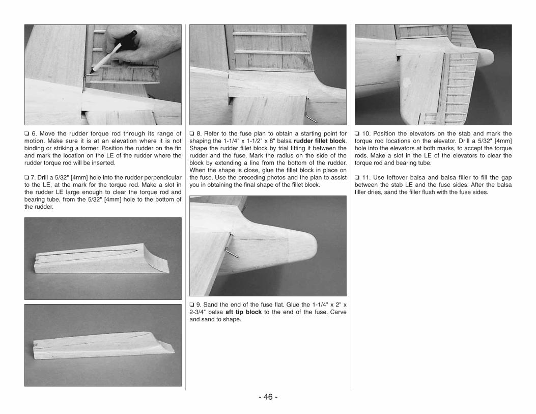
- 46 -
❏ 6. Move the rudder torque rod through its range of motion. Make sure it is at an elevation where it is not binding or striking a former. Position the rudder on the fin and mark the location on the LE of the rudder where the rudder torque rod will be inserted.
❏ 7. Drill a 5/32" [4mm] hole into the rudder perpendicular to the LE, at the mark for the torque rod. Make a slot in the rudder LE large enough to clear the torque rod and bearing tube, from the 5/32" [4mm] hole to the bottom of the rudder.
❏ 8. Refer to the fuse plan to obtain a starting point for shaping the 1-1/4" x 1-1/2" x 8" balsa rudder fillet block. Shape the rudder fillet block by trial fitting it between the rudder and the fuse. Mark the radius on the side of the block by extending a line from the bottom of the rudder. When the shape is close, glue the fillet block in place on the fuse. Use the preceding photos and the plan to assist you in obtaining the final shape of the fillet block.
❏ 9. Sand the end of the fuse flat. Glue the 1-1/4" x 2" x 2-3/4" balsa aft tip block to the end of the fuse. Carve and sand to shape.
❏ 10. Position the elevators on the stab and mark the torque rod locations on the elevator. Drill a 5/32" [4mm] hole into the elevators at both marks, to accept the torque rods. Make a slot in the LE of the elevators to clear the torque rod and bearing tube.
❏ 11. Use leftover balsa and balsa filler to fill the gap between the stab LE and the fuse sides. After the balsa filler dries, sand the filler flush with the fuse sides.
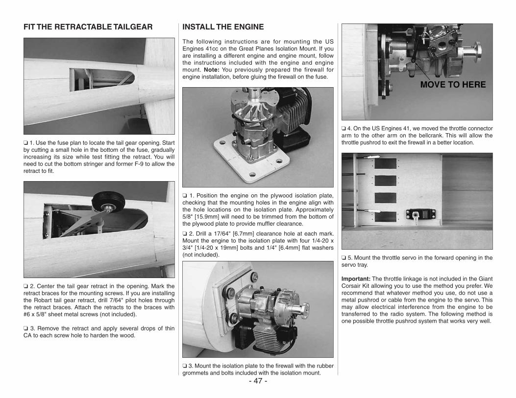
- 47 -
FIT THE RETRACTABLE TAILGEAR
❏ 1. Use the fuse plan to locate the tail gear opening. Start by cutting a small hole in the bottom of the fuse, gradually increasing its size while test fitting the retract. You will need to cut the bottom stringer and former F-9 to allow the retract to fit.
❏ 2. Center the tail gear retract in the opening. Mark the retract braces for the mounting screws. If you are installing the Robart tail gear retract, drill 7/64" pilot holes through the retract braces. Attach the retracts to the braces with #6 x 5/8" sheet metal screws (not included).
❏ 3. Remove the retract and apply several drops of thin CA to each screw hole to harden the wood.
INSTALL THE ENGINE
The following instructions are for mounting the US Engines 41cc on the Great Planes Isolation Mount. If you are installing a different engine and engine mount, follow the instructions included with the engine and engine mount. Note: You previously prepared the firewall for engine installation, before gluing the firewall on the fuse.
❏ 1. Position the engine on the plywood isolation plate, checking that the mounting holes in the engine align with the hole locations on the isolation plate. Approximately 5/8" [15.9mm] will need to be trimmed from the bottom of the plywood plate to provide muffler clearance.
❏ 2. Drill a 17/64" [6.7mm] clearance hole at each mark. Mount the engine to the isolation plate with four 1/4-20 x 3/4" [1/4-20 x 19mm] bolts and 1/4" [6.4mm] flat washers (not included).
❏ 3. Mount the isolation plate to the firewall with the rubber grommets and bolts included with the isolation mount.
❏ 4. On the US Engines 41, we moved the throttle connector arm to the other arm on the bellcrank. This will allow the throttle pushrod to exit the firewall in a better location.
❏ 5. Mount the throttle servo in the forward opening in the servo tray.
Important: The throttle linkage is not included in the Giant Corsair Kit allowing you to use the method you prefer. We recommend that whatever method you use, do not use a metal pushrod or cable from the engine to the servo. This may allow electrical interference from the engine to be transferred to the radio system. The following method is one possible throttle pushrod system that works very well.
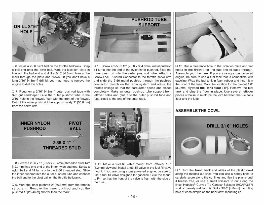
- 48 -
❏ 6. Install a 2-56 pivot ball on the throttle bellcrank. Snap a ball end onto the pivot ball. Mark the isolation plate in line with the ball end and drill a 3/16" [4.8mm] hole at the mark through the plate and firewall. If you don’t have a long 3/16" [4.8mm] drill bit you may need to remove the engine to drill the holes.
❏ 7. Roughen a 3/16" [4.8mm] outer pushrod tube with 320 grit sandpaper. Glue the outer pushrod tube in the 3/16" hole in the firewall, flush with the front of the firewall. Cut off the outer pushrod tube approximately 2" [50.8mm] from the servo arm.
❏ 8. Screw a 2-56 x 1" [2-56 x 25.4mm] threaded stud 1/2" [12.7mm] into one end of the inner nylon pushrod. Screw a nylon ball end 14 turns onto the 2-56 threaded stud. Slide the inner pushrod into the outer pushrod tube and connect the ball end to the pivot ball on the throttle bellcrank.
❏ 9. Mark the inner pushrod 2" [50.8mm] from the throttle servo arm. Remove the inner pushrod and cut the pushrod 1" [25.4mm] shorter than the mark.
❏ 10. Screw a 2-56 x 12" [2-56 x 304.8mm] metal pushrod 14 turns into the end of the nylon inner pushrod. Slide the inner pushrod into the outer pushrod tube. Attach a Screw-Lock Pushrod Connector to the throttle servo arm and slide the 2-56 metal pushrod through the pushrod connector. Switch on the radio system and adjust the throttle linkage so that the carburetor opens and closes completely. Make an outer pushrod tube support from leftover balsa and glue it to the outer pushrod tube and fuse, close to the end of the outer tube.
❏ 11. Make a fuel fill valve mount from leftover 1/8" [3.2mm] plywood. Install a fuel fill valve in the fuel fill valve mount. If you are using a gas powered engine, be sure to use a fuel fill valve designed for gasoline. Glue the mount to F-1 so that the front of the valve is flush with the side of the fuse.
❏ 12. Drill a clearance hole in the isolation plate and two holes in the firewall for the fuel line to pass through. Assemble your fuel tank. If you are using a gas powered engine, be sure to use a fuel tank that is compatible with gasoline. Wrap the fuel tank in foam rubber and insert it in the front of the fuse. Mark the location for the die-cut 1/8" [3.2mm] plywood fuel tank floor (TF). Remove the fuel tank and glue the floor in place. Use several leftover pieces of balsa to reinforce the joint between the fuel tank floor and the fuse.
ASSEMBLE THE COWL
❏ 1. Trim the front, back and sides of the plastic cowl along the molded cut lines. You can use a hobby knife to carefully score along the cut lines and flex the plastic until it breaks free, or use a small scissors to cut along the lines. Hobbico® Curved Tip Canopy Scissors (HCAR0667) work extremely well for this. Drill a 3/16" [4.8mm] mounting hole at each dimple on the back cowl mounting lip.
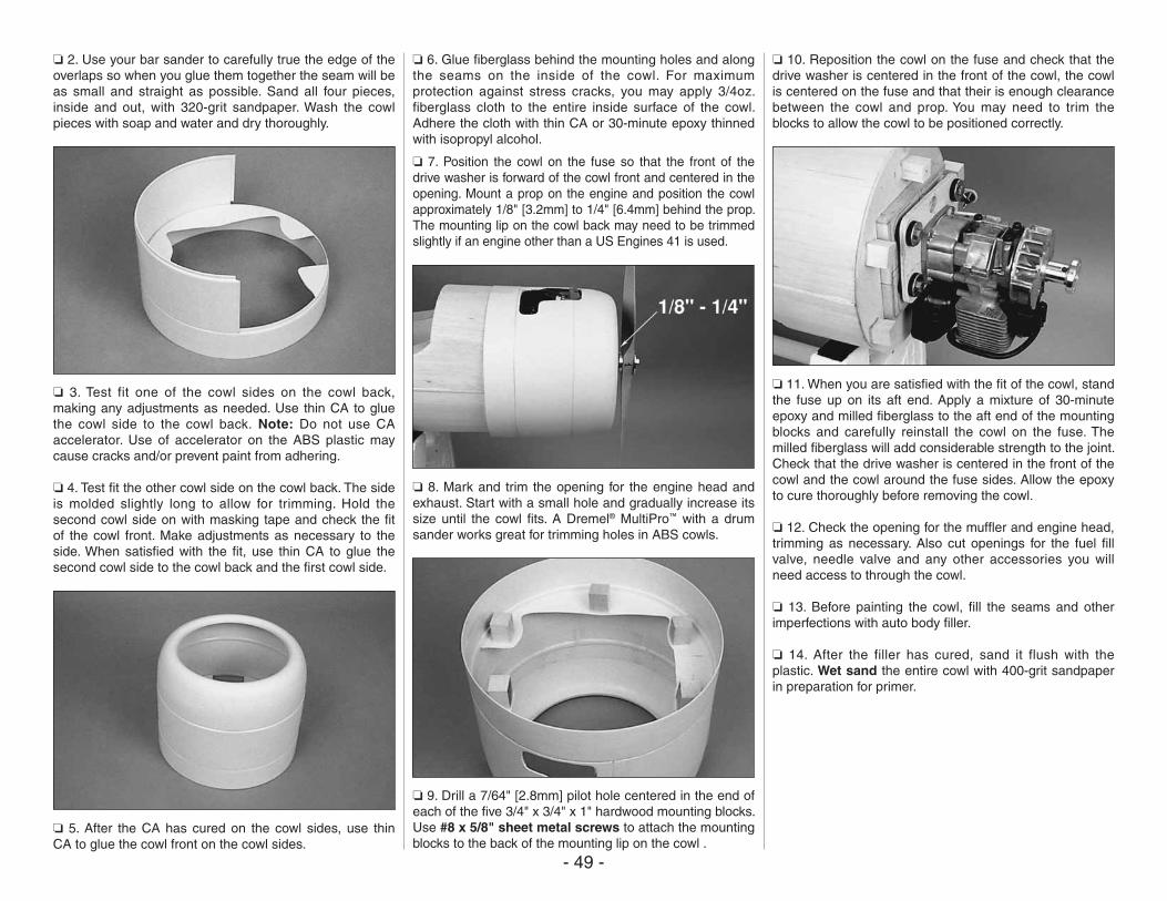
- 49 -
❏ 2. Use your bar sander to carefully true the edge of the overlaps so when you glue them together the seam will be as small and straight as possible. Sand all four pieces, inside and out, with 320-grit sandpaper. Wash the cowl pieces with soap and water and dry thoroughly.
❏ 3. Test fit one of the cowl sides on the cowl back, making any adjustments as needed. Use thin CA to glue the cowl side to the cowl back. Note: Do not use CA accelerator. Use of accelerator on the ABS plastic may cause cracks and/or prevent paint from adhering.
❏ 4. Test fit the other cowl side on the cowl back. The side is molded slightly long to allow for trimming. Hold the second cowl side on with masking tape and check the fit of the cowl front. Make adjustments as necessary to the side. When satisfied with the fit, use thin CA to glue the second cowl side to the cowl back and the first cowl side.
❏ 5. After the CA has cured on the cowl sides, use thin CA to glue the cowl front on the cowl sides.
❏ 6. Glue fiberglass behind the mounting holes and along the seams on the inside of the cowl. For maximum protection against stress cracks, you may apply 3/4oz. fiberglass cloth to the entire inside surface of the cowl. Adhere the cloth with thin CA or 30-minute epoxy thinned with isopropyl alcohol.
❏ 7. Position the cowl on the fuse so that the front of the drive washer is forward of the cowl front and centered in the opening. Mount a prop on the engine and position the cowl approximately 1/8" [3.2mm] to 1/4" [6.4mm] behind the prop. The mounting lip on the cowl back may need to be trimmed slightly if an engine other than a US Engines 41 is used.
❏ 8. Mark and trim the opening for the engine head and exhaust. Start with a small hole and gradually increase its size until the cowl fits. A Dremel® MultiPro™ with a drum sander works great for trimming holes in ABS cowls.
❏ 9. Drill a 7/64" [2.8mm] pilot hole centered in the end of each of the five 3/4" x 3/4" x 1" hardwood mounting blocks. Use #8 x 5/8" sheet metal screws to attach the mounting blocks to the back of the mounting lip on the cowl .
❏ 10. Reposition the cowl on the fuse and check that the drive washer is centered in the front of the cowl, the cowl is centered on the fuse and that their is enough clearance between the cowl and prop. You may need to trim the blocks to allow the cowl to be positioned correctly.
❏ 11. When you are satisfied with the fit of the cowl, stand the fuse up on its aft end. Apply a mixture of 30-minute epoxy and milled fiberglass to the aft end of the mounting blocks and carefully reinstall the cowl on the fuse. The milled fiberglass will add considerable strength to the joint. Check that the drive washer is centered in the front of the cowl and the cowl around the fuse sides. Allow the epoxy to cure thoroughly before removing the cowl.
❏ 12. Check the opening for the muffler and engine head, trimming as necessary. Also cut openings for the fuel fill valve, needle valve and any other accessories you will need access to through the cowl.
❏ 13. Before painting the cowl, fill the seams and other imperfections with auto body filler.
❏ 14. After the filler has cured, sand it flush with the plastic. Wet sand the entire cowl with 400-grit sandpaper in preparation for primer.
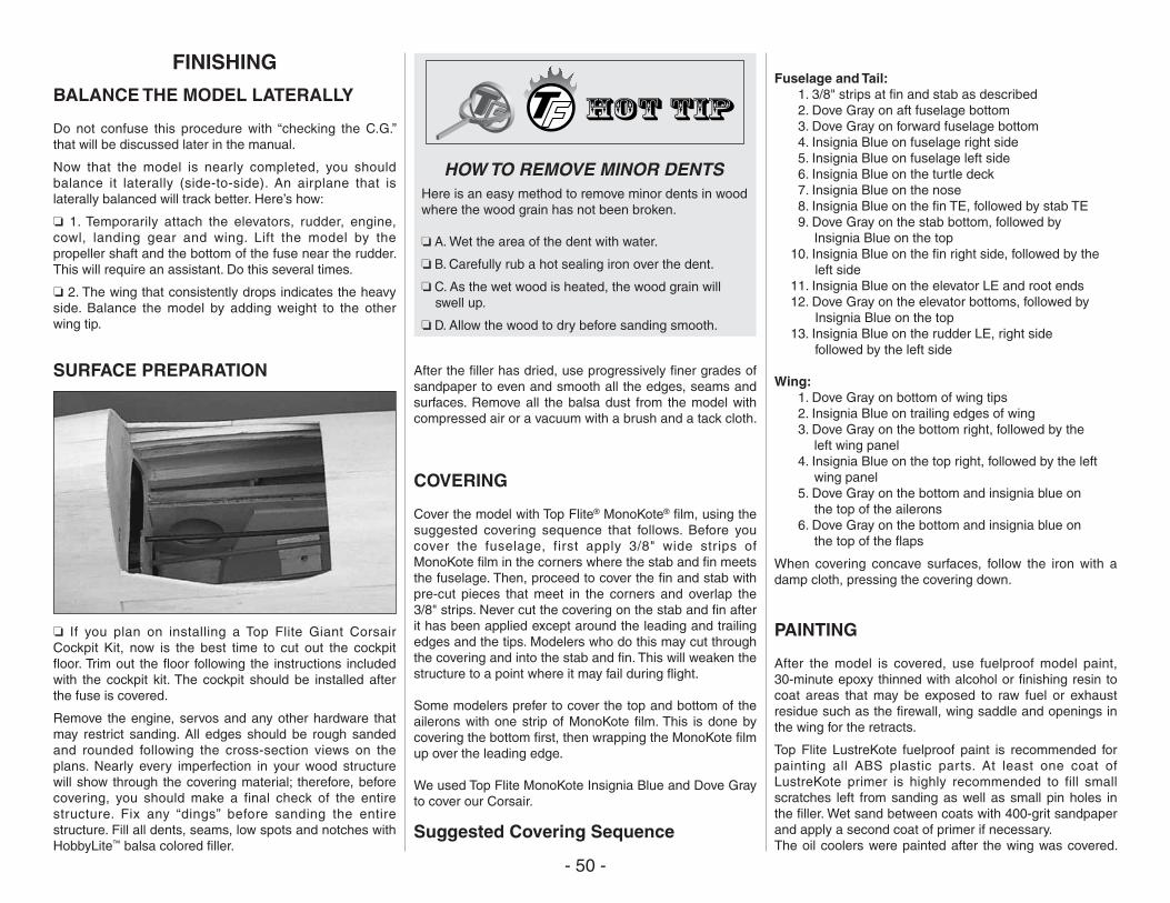
- 50 -
FINISHING
BALANCE THE MODEL LATERALLY
Do not confuse this procedure with “checking the C.G.” that will be discussed later in the manual.
Now that the model is nearly completed, you should balance it laterally (side-to-side). An airplane that is laterally balanced will track better. Here’s how:
❏ 1. Temporarily attach the elevators, rudder, engine, cowl, landing gear and wing. Lift the model by the propeller shaft and the bottom of the fuse near the rudder. This will require an assistant. Do this several times.
❏ 2. The wing that consistently drops indicates the heavy side. Balance the model by adding weight to the other wing tip.
SURFACE PREPARATION
❏ If you plan on installing a Top Flite Giant Corsair Cockpit Kit, now is the best time to cut out the cockpit floor. Trim out the floor following the instructions included with the cockpit kit. The cockpit should be installed after the fuse is covered.
Remove the engine, servos and any other hardware that may restrict sanding. All edges should be rough sanded and rounded following the cross-section views on the plans. Nearly every imperfection in your wood structure will show through the covering material; therefore, before covering, you should make a final check of the entire structure. Fix any “dings” before sanding the entire structure. Fill all dents, seams, low spots and notches with HobbyLite™ balsa colored filler.
HOW TO REMOVE MINOR DENTSHere is an easy method to remove minor dents in wood where the wood grain has not been broken.
❏ A. Wet the area of the dent with water.
❏ B. Carefully rub a hot sealing iron over the dent.
❏ C. As the wet wood is heated, the wood grain will swell up.
❏ D. Allow the wood to dry before sanding smooth.
After the filler has dried, use progressively finer grades of sandpaper to even and smooth all the edges, seams and surfaces. Remove all the balsa dust from the model with compressed air or a vacuum with a brush and a tack cloth.
COVERING
Cover the model with Top Flite® MonoKote® film, using the suggested covering sequence that follows. Before you cover the fuselage, first apply 3/8" wide strips of MonoKote film in the corners where the stab and fin meets the fuselage. Then, proceed to cover the fin and stab with pre-cut pieces that meet in the corners and overlap the 3/8" strips. Never cut the covering on the stab and fin after it has been applied except around the leading and trailing edges and the tips. Modelers who do this may cut through the covering and into the stab and fin. This will weaken the structure to a point where it may fail during flight.
Some modelers prefer to cover the top and bottom of the ailerons with one strip of MonoKote film. This is done by covering the bottom first, then wrapping the MonoKote film up over the leading edge.
We used Top Flite MonoKote Insignia Blue and Dove Gray to cover our Corsair.
Suggested Covering Sequence
Fuselage and Tail: 1. 3/8" strips at fin and stab as described 2. Dove Gray on aft fuselage bottom 3. Dove Gray on forward fuselage bottom 4. Insignia Blue on fuselage right side 5. Insignia Blue on fuselage left side 6. Insignia Blue on the turtle deck 7. Insignia Blue on the nose 8. Insignia Blue on the fin TE, followed by stab TE 9. Dove Gray on the stab bottom, followed by
Insignia Blue on the top 10. Insignia Blue on the fin right side, followed by the
left side 11. Insignia Blue on the elevator LE and root ends 12. Dove Gray on the elevator bottoms, followed by
Insignia Blue on the top 13. Insignia Blue on the rudder LE, right side
followed by the left side
Wing: 1. Dove Gray on bottom of wing tips 2. Insignia Blue on trailing edges of wing 3. Dove Gray on the bottom right, followed by the
left wing panel 4. Insignia Blue on the top right, followed by the left
wing panel 5. Dove Gray on the bottom and insignia blue on
the top of the ailerons 6. Dove Gray on the bottom and insignia blue on
the top of the flaps
When covering concave surfaces, follow the iron with a damp cloth, pressing the covering down.
PAINTING
After the model is covered, use fuelproof model paint, 30-minute epoxy thinned with alcohol or finishing resin to coat areas that may be exposed to raw fuel or exhaust residue such as the firewall, wing saddle and openings in the wing for the retracts.
Top Flite LustreKote fuelproof paint is recommended for painting all ABS plastic parts. At least one coat of LustreKote primer is highly recommended to fill small scratches left from sanding as well as small pin holes in the filler. Wet sand between coats with 400-grit sandpaper and apply a second coat of primer if necessary.The oil coolers were painted after the wing was covered.
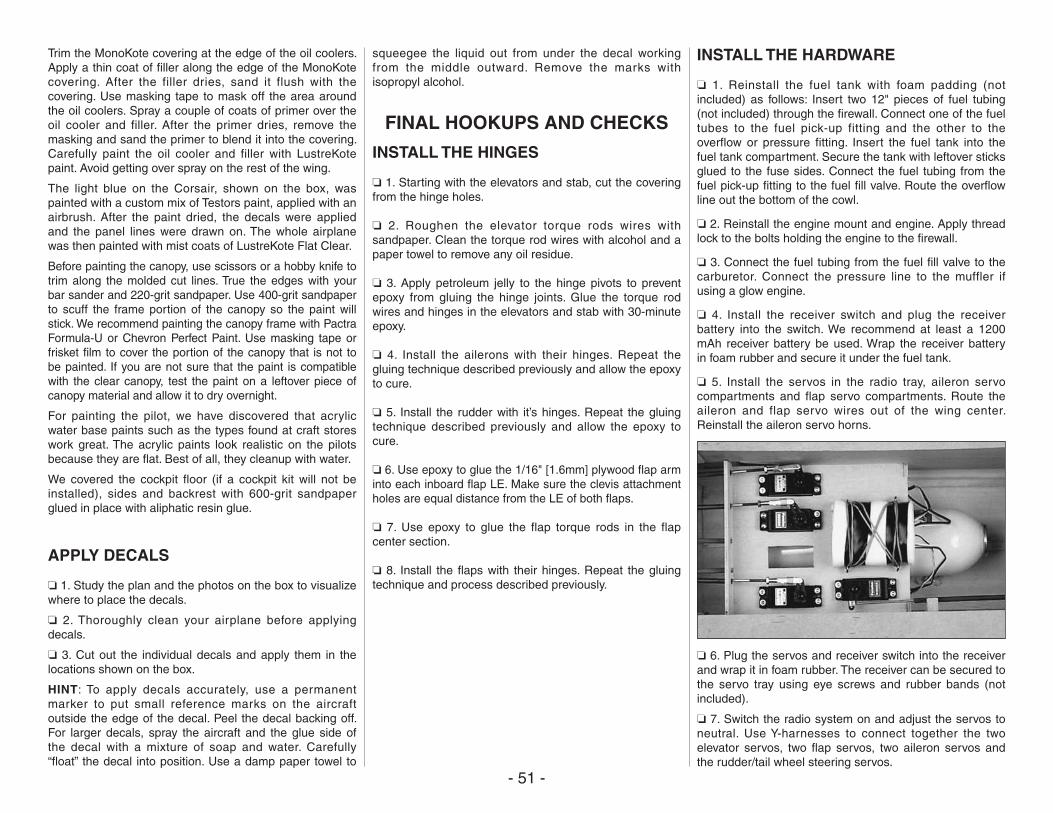
- 51 -
Trim the MonoKote covering at the edge of the oil coolers. Apply a thin coat of filler along the edge of the MonoKote covering. After the filler dries, sand it flush with the covering. Use masking tape to mask off the area around the oil coolers. Spray a couple of coats of primer over the oil cooler and filler. After the primer dries, remove the masking and sand the primer to blend it into the covering. Carefully paint the oil cooler and filler with LustreKote paint. Avoid getting over spray on the rest of the wing.
The light blue on the Corsair, shown on the box, was painted with a custom mix of Testors paint, applied with an airbrush. After the paint dried, the decals were applied and the panel lines were drawn on. The whole airplane was then painted with mist coats of LustreKote Flat Clear.
Before painting the canopy, use scissors or a hobby knife to trim along the molded cut lines. True the edges with your bar sander and 220-grit sandpaper. Use 400-grit sandpaper to scuff the frame portion of the canopy so the paint will stick. We recommend painting the canopy frame with Pactra Formula-U or Chevron Perfect Paint. Use masking tape or frisket film to cover the portion of the canopy that is not to be painted. If you are not sure that the paint is compatible with the clear canopy, test the paint on a leftover piece of canopy material and allow it to dry overnight.
For painting the pilot, we have discovered that acrylic water base paints such as the types found at craft stores work great. The acrylic paints look realistic on the pilots because they are flat. Best of all, they cleanup with water.
We covered the cockpit floor (if a cockpit kit will not be installed), sides and backrest with 600-grit sandpaper glued in place with aliphatic resin glue.
APPLY DECALS
❏ 1. Study the plan and the photos on the box to visualize where to place the decals.
❏ 2. Thoroughly clean your airplane before applying decals.
❏ 3. Cut out the individual decals and apply them in the locations shown on the box.
HINT: To apply decals accurately, use a permanent marker to put small reference marks on the aircraft outside the edge of the decal. Peel the decal backing off. For larger decals, spray the aircraft and the glue side of the decal with a mixture of soap and water. Carefully “float” the decal into position. Use a damp paper towel to
squeegee the liquid out from under the decal working from the middle outward. Remove the marks with isopropyl alcohol.
FINAL HOOKUPS AND CHECKS
INSTALL THE HINGES
❏ 1. Starting with the elevators and stab, cut the covering from the hinge holes.
❏ 2. Roughen the elevator torque rods wires with sandpaper. Clean the torque rod wires with alcohol and a paper towel to remove any oil residue.
❏ 3. Apply petroleum jelly to the hinge pivots to prevent epoxy from gluing the hinge joints. Glue the torque rod wires and hinges in the elevators and stab with 30-minute epoxy.
❏ 4. Install the ailerons with their hinges. Repeat the gluing technique described previously and allow the epoxy to cure.
❏ 5. Install the rudder with it’s hinges. Repeat the gluing technique described previously and allow the epoxy to cure.
❏ 6. Use epoxy to glue the 1/16" [1.6mm] plywood flap arm into each inboard flap LE. Make sure the clevis attachment holes are equal distance from the LE of both flaps.
❏ 7. Use epoxy to glue the flap torque rods in the flap center section.
❏ 8. Install the flaps with their hinges. Repeat the gluing technique and process described previously.
INSTALL THE HARDWARE
❏ 1. Reinstall the fuel tank with foam padding (not included) as follows: Insert two 12" pieces of fuel tubing (not included) through the firewall. Connect one of the fuel tubes to the fuel pick-up fitting and the other to the overflow or pressure fitting. Insert the fuel tank into the fuel tank compartment. Secure the tank with leftover sticks glued to the fuse sides. Connect the fuel tubing from the fuel pick-up fitting to the fuel fill valve. Route the overflow line out the bottom of the cowl.
❏ 2. Reinstall the engine mount and engine. Apply thread lock to the bolts holding the engine to the firewall.
❏ 3. Connect the fuel tubing from the fuel fill valve to the carburetor. Connect the pressure line to the muffler if using a glow engine.
❏ 4. Install the receiver switch and plug the receiver battery into the switch. We recommend at least a 1200 mAh receiver battery be used. Wrap the receiver battery in foam rubber and secure it under the fuel tank.
❏ 5. Install the servos in the radio tray, aileron servo compartments and flap servo compartments. Route the aileron and flap servo wires out of the wing center. Reinstall the aileron servo horns.
❏ 6. Plug the servos and receiver switch into the receiver and wrap it in foam rubber. The receiver can be secured to the servo tray using eye screws and rubber bands (not included).
❏ 7. Switch the radio system on and adjust the servos to neutral. Use Y-harnesses to connect together the two elevator servos, two flap servos, two aileron servos and the rudder/tail wheel steering servos.
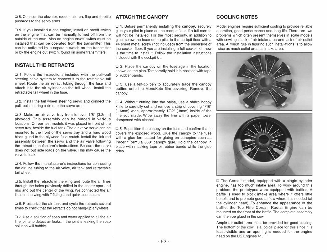
- 52 -
❏ 8. Connect the elevator, rudder, aileron, flap and throttle pushrods to the servo arms.
❏ 9. If you installed a gas engine, install an on/off switch on the engine that can be manually turned off from the outside of the cowl. Also an engine on/off switch must be installed that can be operated from the transmitter. This can be activated by a separate switch on the transmitter or by the engine cut switch, found on some transmitters.
INSTALL THE RETRACTS
❏ 1. Follow the instructions included with the pull–pull steering cable system to connect it to the retractable tail wheel. Route the air retract tubing through the fuse and attach it to the air cylinder on the tail wheel. Install the retractable tail wheel in the fuse.
❏ 2. Install the tail wheel steering servo and connect the pull–pull steering cables to the servo arm.
❏ 3. Make an air valve tray from leftover 1/8" [3.2mm] plywood. This assembly can be placed in various locations. On our test models it was placed in front of the servo tray, beside the fuel tank. The air valve servo can be mounted to the front of the servo tray and a hard wood block glued to the plywood fuse crutch. Install the link rod assembly between the servo and the air valve following the retract manufacturer’s instructions. Be sure the servo does not put side loads on the valve. This may cause the valve to leak.
❏ 4. Follow the manufacturer’s instructions for connecting the air line tubing to the air valve, air tank and retractable tail wheel.
❏ 5. Install the retracts in the wing and route the air lines through the holes previously drilled in the center spar and ribs and out the center of the wing. We connected the air lines in the wing with T-fittings and quick connectors.
❏ 6. Pressurize the air tank and cycle the retracts several times to check that the retracts do not hang-up anywhere.
❏ 7. Use a solution of soap and water applied to all the air line joints to detect air leaks. If the joint is leaking the soap solution will bubble.
ATTACH THE CANOPY
❏ 1. Before permanently installing the canopy, securely glue your pilot in place on the cockpit floor, if a full cockpit will not be installed. For the most security, in addition to glue, screw the base of the pilot to the cockpit floor with a #4 sheet metal screw (not included) from the underside of the cockpit floor. If you are installing a full cockpit kit, now is the time to install it. Follow the installation instructions included with the cockpit kit.
❏ 2. Place the canopy on the fuselage in the location shown on the plan. Temporarily hold it in position with tape or rubber bands.
❏ 3. Use a felt-tip pen to accurately trace the canopy outline onto the MonoKote film covering. Remove the canopy.
❏ 4. Without cutting into the balsa, use a sharp hobby knife to carefully cut and remove a strip of covering 1/16" [1.6mm] wide, approximately 1/32" (.8mm] inside of the line you made. Wipe away the line with a paper towel dampened with alcohol.
❏ 5. Reposition the canopy on the fuse and confirm that it covers the exposed wood. Glue the canopy to the fuse with a glue formulated for gluing on canopies such as Pacer “Formula 560” canopy glue. Hold the canopy in place with masking tape or rubber bands while the glue dries.
COOLING NOTES
Model engines require sufficient cooling to provide reliable operation, good performance and long life. There are two problems which often present themselves in scale models with cowlings: lack of air intake area and lack of air outlet area. A rough rule in figuring such installations is to allow twice as much outlet area as intake area.
❏ The Corsair model, equipped with a single cylinder engine, has too much intake area. To work around this problem, the prototypes were equipped with baffles. A baffle is used to block intake area where it offers little benefit and to promote good airflow where it is needed (at the cylinder head). To enhance the appearance of the baffle, the Top Flite Corsair Radial Engine can be mounted on the front of the baffle. The complete assembly can then be glued in the cowl.
Ample air outlet area must be provided for good cooling. The bottom of the cowl is a logical place for this since it is least visible and an opening is needed for the engine head on the US Engines 41.
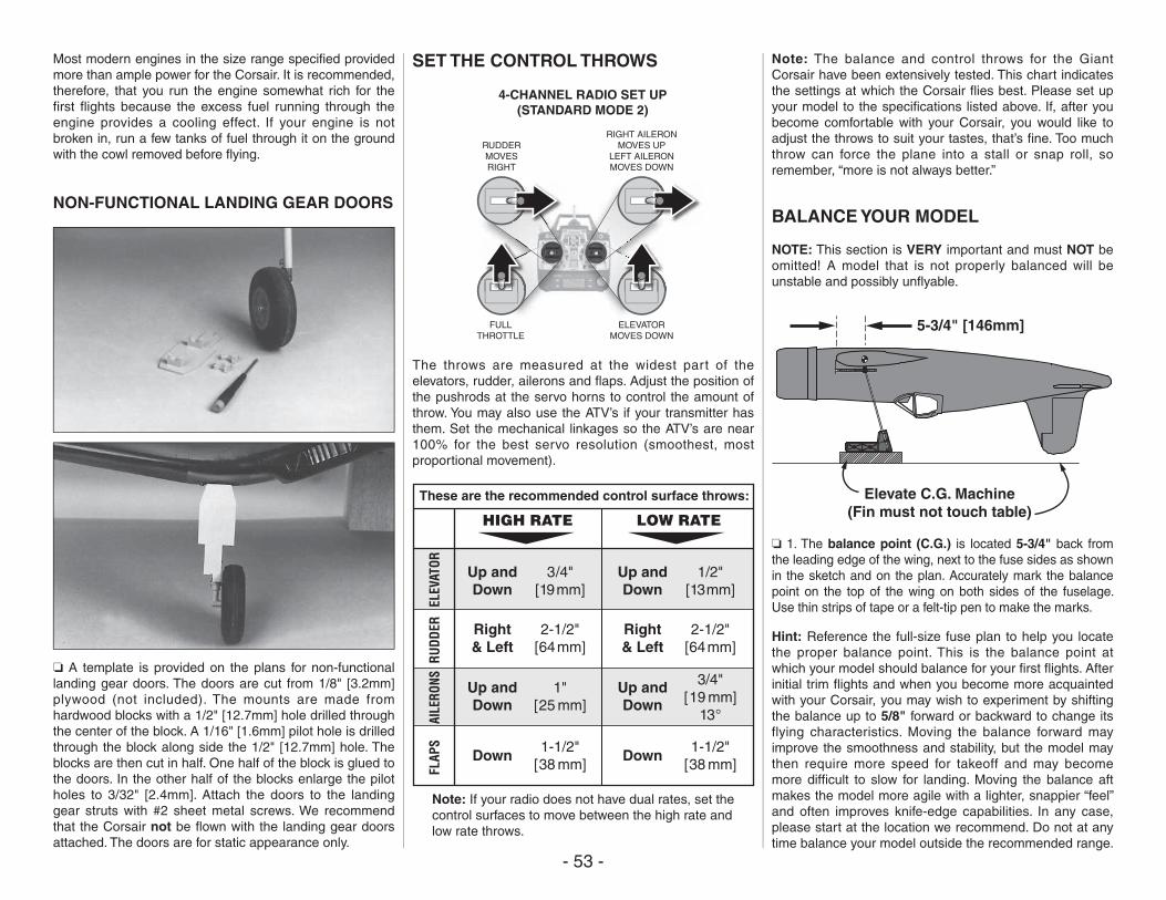
- 53 -
Most modern engines in the size range specified provided more than ample power for the Corsair. It is recommended, therefore, that you run the engine somewhat rich for the first flights because the excess fuel running through the engine provides a cooling effect. If your engine is not broken in, run a few tanks of fuel through it on the ground with the cowl removed before flying.
NON-FUNCTIONAL LANDING GEAR DOORS
❏ A template is provided on the plans for non-functional landing gear doors. The doors are cut from 1/8" [3.2mm] plywood (not included). The mounts are made from hardwood blocks with a 1/2" [12.7mm] hole drilled through the center of the block. A 1/16" [1.6mm] pilot hole is drilled through the block along side the 1/2" [12.7mm] hole. The blocks are then cut in half. One half of the block is glued to the doors. In the other half of the blocks enlarge the pilot holes to 3/32" [2.4mm]. Attach the doors to the landing gear struts with #2 sheet metal screws. We recommend that the Corsair not be flown with the landing gear doors attached. The doors are for static appearance only.
SET THE CONTROL THROWS
FULLTHROTTLE
RUDDERMOVESRIGHT
ELEVATORMOVES DOWN
RIGHT AILERONMOVES UP
LEFT AILERONMOVES DOWN
4-CHANNEL RADIO SET UP(STANDARD MODE 2)
The throws are measured at the widest part of the elevators, rudder, ailerons and flaps. Adjust the position of the pushrods at the servo horns to control the amount of throw. You may also use the ATV’s if your transmitter has them. Set the mechanical linkages so the ATV’s are near 100% for the best servo resolution (smoothest, most proportional movement).
2-1/2"[64mm]
3/4"[19mm]
These are the recommended control surface throws:
ELEV
ATOR
HIGH RATE LOW RATE
Up andDown
Up andDown
Up andDown
Down
1"[25 mm]
Up andDown
Down
3/4"[19 mm]
13°
1-1/2"[38 mm]
1-1/2"[38 mm]
Right& Left
Right& Left
2-1/2"[64mm]
RUDD
ERAI
LERO
NSFL
APS
1/2"[13mm]
Note: If your radio does not have dual rates, set thecontrol surfaces to move between the high rate andlow rate throws.
Note: The balance and control throws for the Giant Corsair have been extensively tested. This chart indicates the settings at which the Corsair flies best. Please set up your model to the specifications listed above. If, after you become comfortable with your Corsair, you would like to adjust the throws to suit your tastes, that’s fine. Too much throw can force the plane into a stall or snap roll, so remember, “more is not always better.”
BALANCE YOUR MODEL
NOTE: This section is VERY important and must NOT be omitted! A model that is not properly balanced will be unstable and possibly unflyable.
5-3/4" [146mm]
Elevate C.G. Machine(Fin must not touch table)
❏ 1. The balance point (C.G.) is located 5-3/4" back from the leading edge of the wing, next to the fuse sides as shown in the sketch and on the plan. Accurately mark the balance point on the top of the wing on both sides of the fuselage. Use thin strips of tape or a felt-tip pen to make the marks.
Hint: Reference the full-size fuse plan to help you locate the proper balance point. This is the balance point at which your model should balance for your first flights. After initial trim flights and when you become more acquainted with your Corsair, you may wish to experiment by shifting the balance up to 5/8" forward or backward to change its flying characteristics. Moving the balance forward may improve the smoothness and stability, but the model may then require more speed for takeoff and may become more difficult to slow for landing. Moving the balance aft makes the model more agile with a lighter, snappier “feel” and often improves knife-edge capabilities. In any case, please start at the location we recommend. Do not at any time balance your model outside the recommended range.
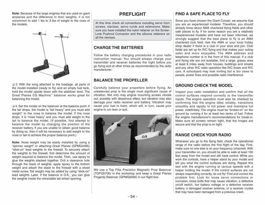
- 54 -
Note: Because of the large engines that are used on giant airplanes and the difference in their weights, it is not uncommon to add 1 lbs to 3 lbs of weight to the nose of the models.
❏ 2. With the wing attached to the fuselage, all parts of the model installed (ready to fly) and an empty fuel tank, hold the model upside down with the stabilizer level. The Great Planes CG Machine™ balancer works great for balancing the model.
❏ 3. Set the model on the balancer at the balance point. If the tail drops, the model is “tail heavy” and you must add weight* to the nose to balance the model. If the nose drops, it is “nose heavy” and you must add weight to the tail to balance the model. (If possible, first attempt to balance the model by changing the position of the receiver battery. If you are unable to obtain good balance by doing so, then it will be necessary to add weight to the nose or tail to achieve the proper balance point.)
Note: Nose weight may be easily installed by using a “spinner weight” or attaching Great Planes (GPMQ4485) “stick-on” lead weights to the firewall. To securely attach the weights to the firewall, first determine the amount of weight required to balance the model. Then, use epoxy to glue the weights stacked together. Drill a clearance hole through the stack of weights, apply epoxy to the bottom weight and attach the stack to the firewall with a sheet metal screw. Tail weight may be added by using “stick-on” lead weights. Later, if the balance is O.K., you can glue the weights inside the retractable tail wheel opening.
PREFLIGHT
At this time check all connections including servo horn screws, clevises, servo cords and extensions. Make sure you have installed the nylon retainer on the Screw-Lock Pushrod Connector and the silicone retainers on all the clevises.
CHARGE THE BATTERIES
Follow the battery charging procedures in your radio instruction manual. You should always charge your transmitter and receiver batteries the night before you go flying and at other times as recommended by the radio manufacturer.
BALANCE THE PROPELLER
Carefully balance your propellers before flying. An unbalanced prop is the single most significant cause of vibration. Not only may engine mounting screws vibrate out, possibly with disastrous effect, but vibration may also damage your radio receiver and battery. Vibration may cause your fuel to foam, which will, in turn, cause your engine to run lean or quit.
We use a Top Flite Precision Magnetic Prop Balancer (TOPQ5700) in the workshop and keep a Great Planes Fingertip Balancer (GPMQ5000) in our flight box.
FIND A SAFE PLACE TO FLY
Since you have chosen the Giant Corsair, we assume that you are an experienced modeler. Therefore, you should already know about AMA chartered flying fields and other safe places to fly. If for some reason you are a relatively inexperienced modeler and have not been informed, we strongly suggest that the best place to fly is an AMA chartered club field. Ask the AMA or your local hobby shop dealer if there is a club in your area and join. Club fields are set up for R/C flying and that makes your outing safer and more enjoyable. The AMA address and telephone number is in the front of this manual. If a club and flying site are not available, find a large, grassy area at least 6 miles away from houses, buildings and streets and any other R/C radio operation like R/C boats and R/C cars. A schoolyard may look inviting but is too close to people, power lines and possible radio interference.
GROUND CHECK THE MODELInspect your radio installation and confirm that all the control surfaces respond correctly to the transmitter inputs. The engine operation must also be checked by confirming that the engine idles reliably, transitions smoothly and rapidly to full power and maintains full power, indefinitely. The engine must be “broken-in” on the ground by running it for at least two tanks of fuel. Follow the engine manufacturer’s recommendations for break-in. Make sure all screws remain tight, that the hinges are secure and that the prop is on tight.
RANGE CHECK YOUR RADIOWhenever you go to the flying field, check the operational range of the radio before the first flight of the day. First, make sure no one else is on your frequency (channel). With your transmitter on, you should be able to walk at least 100 feet away from the model and still have control. While you work the controls, have a helper stand by your model and tell you what the control surfaces are doing. Repeat this test with the engine running at various speeds with a helper holding the model. If the control surfaces are not always responding correctly, do not fly! Find and correct the problem first. Look for loose servo connections or corrosion, loose bolts that may cause vibration, a defective on/off switch, low battery voltage or a defective receiver battery, a damaged receiver antenna, or a receiver crystal that may have been damaged from a previous crash.
- 55 -
ENGINE SAFETY PRECAUTIONS
Note: Failure to follow these safety precautions may result in severe injury to yourself and others.
Keep all engine fuel in a safe place, away from high heat, sparks or flames, as fuel is very flammable. Do not smoke near the engine or fuel; and remember that the engine exhaust gives off a great deal of deadly carbon monoxide.
Do not run the engine in a closed room or garage.
Get help from an experienced pilot when learning to operate engines.
Be sure to use safety glasses when starting or running engines.
Do not run the engine in an area of loose gravel or sand; the propeller may throw such material in your face or eyes.
Keep your face and body as well as all spectators away from the plane of rotation of the propeller as you start and run the engine.
Keep these items away from the prop: loose clothing, shirt sleeves, ties, scarfs, long hair or loose objects such as pencils or screwdrivers that may fall out of shirt or jacket pockets into the prop.
Use a “chicken stick” or electric starter to start the engine. Do not use your fingers to flip the propeller. Make certain the glow plug clip or connector is secure so that it will not pop off or otherwise get into the running propeller.
Make all engine adjustments from behind the propeller.
The engine gets hot! Do not touch it during or right after operation. Make sure fuel lines are in good condition so fuel will not leak onto a hot engine, causing a fire.
To stop a glow engine, cut off the fuel supply by closing off the fuel line or following the engine manufacturer’s recommendations. Do not use hands, fingers or any other body part to try to stop the engine. To stop a gasoline powered engine an on/off switch should be connected to the engine coil. Do not throw anything into the propeller of a running engine.
AMA SAFETY CODE (excerpts)
Read and abide by the following Academy of Model Aeronautics Official Safety Code:
GENERAL
1. I will not fly my model aircraft in sanctioned events, air shows, or model flying demonstrations until it has been proven to be airworthy by having been previously successfully flight tested.
2. I will not fly my model aircraft higher than approximately 400 feet within 3 miles of an airport without notifying the airport operator. I will give right of way to and avoid flying in the proximity of full-scale aircraft. Where necessary an observer shall be used to supervise flying to avoid having models fly in the proximity of full-scale aircraft.
3. Where established, I will abide by the safely rules for the flying site I use and I will not willfully and deliberately fly my models in a careless, reckless and/or dangerous manner.
7. I will not fly my model unless it is identified with my name and address or AMA number, on or in the model.
9. I will not operate models with pyrotechnics (any device that explodes, burns, or propels a projectile or any kind).
RADIO CONTROL
1. I will have completed a successful radio equipment ground check before the first flight of a new or repaired model
2. I will not fly my model aircraft in the presence of spectators until I become a qualified flier, unless assisted by an experienced helper.
3. I will perform my initial turn after takeoff away from the pit or spectator areas and I will not thereafter fly over pit or spectator areas, unless beyond my control.
4. I will operate my model using only radio control f requencies current ly a l lowed by the Federal Communications Commission.
IMAA SAFETY CODE (excerpts)
Definition: For the purpose of the following IMAA Safety Code, the term Giant Scale shall refer to radio controlled model aircraft, either scale or non-scale, which have a wingspan of 80 inches or more for monoplanes and 60 inches or more for multi-winged model aircraft and have a ramp weight (fueled and ready to fly) of 55 lbs or less.
Section 1.0: SAFETY STANDARD
1.1 Adherence to Code: This safety code is to be strictly followed.
1.2 The most current AMA Safety Code in effect is to be observed. However, the competition sections of the code may be disregarded.
Section 3.0: Safety Check
3.4 Flight Testing: All Giant Scale R/C aircraft are to have been flight tested and flight trimmed with a minimum of six flights before the model is allowed to fly at an IMAA Sanctioned event.
3.5 Proof of Flight: The completing and signing of the Declaration section of the Safety Inspection form by the pilot (or owner) shall document as fact that each aircraft has been successfully flight-tested and proven airworthy prior to an IMAA event.
Section 5.0: EMERGENCY ENGINE SHUT OFF (kill switch)
5.1 All magneto spark ignition engines must have a coil grounding switch on the aircraft to stop the engine. This will also prevent accidental starting of the engine. This switch shall be readily available to both pilot and helper. This switch is to be operated manually and without the use of the radio system.
5.2 Engines with battery power ignition systems must have a switch to turn off the power from the battery pack to disable the engine from firing. This will also prevent accidental starting of the engine. This switch shall be readily available to both pilot and helper. This switch shall be operated manually and without the use of the Radio System.
- 56 -
5.3 There must also be a means to stop the engine from the transmitter. The most common method is to close the carburetor throat completely using throttle trim, however, other methods are acceptable. This requirement applies to all glow/gas ignition engines regardless of size.
Section 6.0: RADIO REQUIREMENTS
6.1 All transmitters must be FCC type certified.
6.2 FCC Technician or higher-class license required for 6 meter band operation only.
Additional General Recommendations
Servo need to be of rating capable to handle the loads that the control surfaces impose upon the servos. Standard servos are not recommended for control surfaces. Servos should be rated heavy-duty. For flight-critical control functions a minimum of 45 inch/ounces of torque should be considered. This should be considered a minimum for smaller aircraft and higher torque servos are strongly encouraged for larger aircraft. The use of one servo for each aileron and one for each elevator half is strongly recommended. Use of duel servos is also recommended for larger aircraft.
On-board batteries shall be 1000 mAh up to 20 lbs, 1200 mAh to 30 lbs, 1800 mAh to 40 lbs. And 2000mAh over 40 lbs flying weight. The number and size of servos, size and loads on control surfaces and added features should be considered as an increase to these minimums. Batteries should be able to sustain power to the onboard radio components for a minimum of one hour total flying time before recharging.
Redundant and fa i l -safe bat ter y systems are recommended.
The use of anti-glitch devices for long leads are recommended.
There is no maximum engine displacement limit, as it is the position of this body that an underpowered aircraft presents a greater danger than an overpowered aircraft. However, the selection of engine size relative to airframe strength and power loading mandates good discretionary judgement by the designer and builder. Current AMA
maximums for engine displacement are 6.0 cu. in. for two-stroke and 9.6 cu. in. for four-stroke engines. These maximums apply only to AMA Sanctions concerning competition events (such as 511, 512, 515 and 520) and, as such, the maximums apply. All IMAA (non competition) events should be sanctioned as Class “C” events, in which these engine size maximums do not apply.
Generally, it is recommended that no attempt should be made to fly a radio controlled model aircraft with a gasoline engine in which the model aircraft weight would exceed twelve [12) pounds (underpowered) per cubic inch of engine displacement, or be less than five (5) pounds (overpowered) per cubic inch of engine displacement. Example: Using a 3 cu. in. engine, a model would likely be underpowered at an aircraft weight greater than 36 pounds. With the same engine, an aircraft weighing less than 15 pounds would likely be overpowered.
Servo arms and wheels should be rated heavy duty. Glass f i l led servo arms and control horns are highly recommended.
Control surface linkages are listed in order of preference:
1. Cable system (pull-pull). A til ler bar is highly recommended along with necessary bracing.
2. Arrow Shaft, fiberglass or aluminum, 1/4" or 5/16" O.D. bracing every six (6) to ten [10) inches is highly recommended.
3. Tube-in-tube (Nyrod). Bracing every few inches is highly recommended. Inner tube should be totally enclosed in outer tube.
4. Hardwood dowel, 3/8" O.D. bracing every six (6) to ten [10) inches is highly recommended.
Hinges should be rated heavy duty and manufactured for Giant Scale use primarily. Homemade and original design hinges are acceptable if determined to be adequate for the intended use.
Clevis (steel, excluding heavy-duty ball links) and attachment hardware should be heavy duty 4-40 threaded rod type. 2-56 threaded size rod is acceptable for some applications (e.g. throttle). Clevis is to have lock nuts and sleeve or spring keepers.
Propeller tips should be painted or colored in a visible and contrasting manner so as to increase the visibility of the propeller tip arc.
FLYING
The Top Flite Giant Corsair is a great-flying scale warbird that flies smoothly and predictably. The Corsair does not, however, possess the self-recovery characteristics of a primary R/C trainer and should only be flown by experienced RC Pilots.
CAUTION (THIS APPLIES TO ALL R/C AIRPLANES): If, while flying, you notice any unusual sounds, such as a low-pitched "buzz," this may indicate control surface flutter. Because flutter can quickly destroy components of your airplane, any time you detect flutter you must immediately cut the throttle and land the airplane! Check all servo grommets for deterioration (this may indicate which surface fluttered), and make sure all pushrod linkages are secure and free of play. If the control surface fluttered once, it probably will flutter again under similar circumstances unless you can eliminate the free-play or flexing in the linkages. Here are some things which can cause flutter: Excessive hinge gap; Not mounting control horns solidly; Poor fit of clevis pin in horn; Side-play of pushrod in guide tube caused by tight bends; Poor fit of Z-bend in servo arm; Insufficient glue used when gluing in the elevator joiner wire; Excessive play or backlash in servo gears; and Insecure servo mounting.
FUEL MIXTURE ADJUSTMENTS
A fully cowled engine may run at a higher temperature than an uncowled engine. For this reason, the fuel mixture should be richened so the engine runs at about 200 rpm below peak speed. By running the engine slightly rich, you will help prevent dead stick landings caused by overheating.
TAKEOFF
Takeoff on “high” rates if you have dual rates on your transmitter and with the flaps up - especially if you are taking off into a crosswind. For all models it is good practice to gain as much speed as the length of the runway will permit before lifting off. This will give you a safety margin in case the engine quits. When the plane has gained enough flying speed to safely lift off, gradually and smoothly apply up elevator and allow the model to climb at a shallow angle (do not yank the model off the ground into a steep climb!)
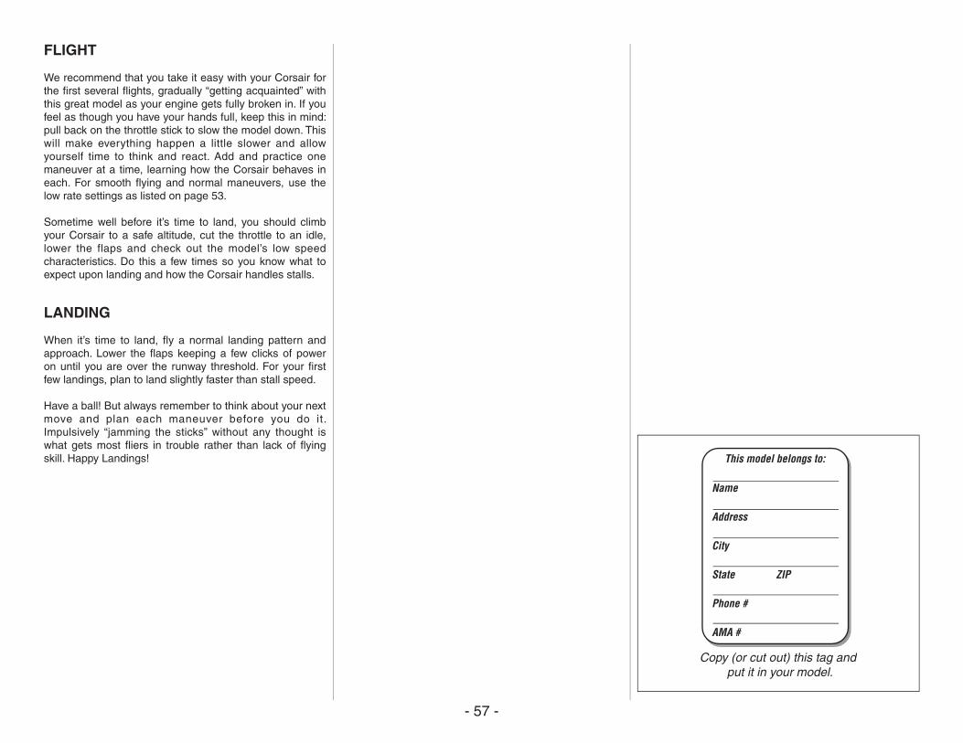
- 57 -
FLIGHT
We recommend that you take it easy with your Corsair for the first several flights, gradually “getting acquainted” with this great model as your engine gets fully broken in. If you feel as though you have your hands full, keep this in mind: pull back on the throttle stick to slow the model down. This will make everything happen a little slower and allow yourself time to think and react. Add and practice one maneuver at a time, learning how the Corsair behaves in each. For smooth flying and normal maneuvers, use the low rate settings as listed on page 53.
Sometime well before it’s time to land, you should climb your Corsair to a safe altitude, cut the throttle to an idle, lower the flaps and check out the model’s low speed characteristics. Do this a few times so you know what to expect upon landing and how the Corsair handles stalls.
LANDING
When it’s time to land, fly a normal landing pattern and approach. Lower the flaps keeping a few clicks of power on until you are over the runway threshold. For your first few landings, plan to land slightly faster than stall speed.
Have a ball! But always remember to think about your next move and plan each maneuver before you do it. Impulsively “jamming the sticks” without any thought is what gets most fliers in trouble rather than lack of flying skill. Happy Landings! This model belongs to:
Copy (or cut out) this tag and put it in your model.
Name
Address
City
State ZIP
Phone #
AMA #
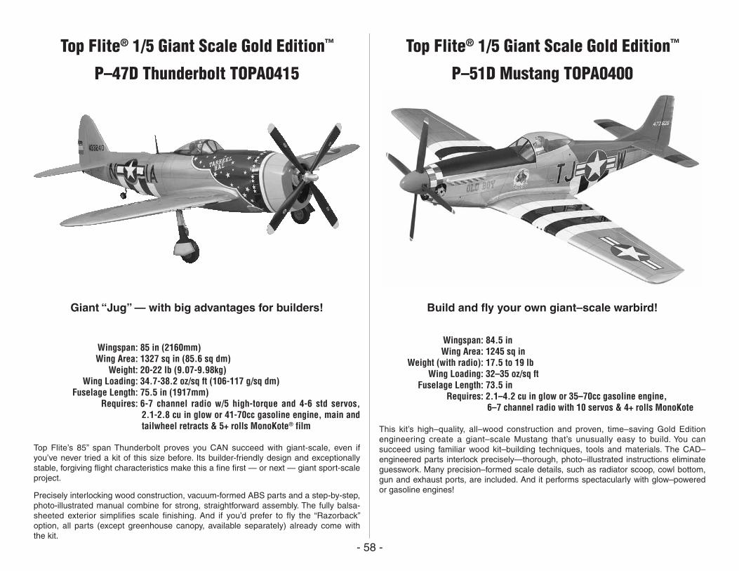
- 58 -
Build and fly your own giant–scale warbird!
Wingspan: 84.5 in Wing Area: 1245 sq in Weight (with radio): 17.5 to 19 lb Wing Loading: 32–35 oz/sq ft Fuselage Length: 73.5 in Requires: 2.1–4.2 cu in glow or 35–70cc gasoline engine,
6–7 channel radio with 10 servos & 4+ rolls MonoKote
This kit’s high–quality, all–wood construction and proven, time–saving Gold Edition engineering create a giant–scale Mustang that’s unusually easy to build. You can succeed using familiar wood kit–building techniques, tools and materials. The CAD–engineered parts interlock precisely—thorough, photo–illustrated instructions eliminate guesswork. Many precision–formed scale details, such as radiator scoop, cowl bottom, gun and exhaust ports, are included. And it performs spectacularly with glow–powered or gasoline engines!
Giant “Jug” — with big advantages for builders!
Wingspan: 85 in (2160mm) Wing Area: 1327 sq in (85.6 sq dm) Weight: 20-22 lb (9.07-9.98kg) Wing Loading: 34.7-38.2 oz/sq ft (106-117 g/sq dm) Fuselage Length: 75.5 in (1917mm) Requires: 6-7 channel radio w/5 high-torque and 4-6 std servos,
2.1-2.8 cu in glow or 41-70cc gasoline engine, main and tailwheel retracts & 5+ rolls MonoKote® film
Top Flite’s 85” span Thunderbolt proves you CAN succeed with giant-scale, even if you’ve never tried a kit of this size before. Its builder-friendly design and exceptionally stable, forgiving flight characteristics make this a fine first — or next — giant sport-scale project.
Precisely interlocking wood construction, vacuum-formed ABS parts and a step-by-step, photo-illustrated manual combine for strong, straightforward assembly. The fully balsa-sheeted exterior simplifies scale finishing. And if you’d prefer to fly the “Razorback” option, all parts (except greenhouse canopy, available separately) already come with the kit.
Top Flite® 1/5 Giant Scale Gold Edition™
P–51D Mustang TOPA0400
Top Flite® 1/5 Giant Scale Gold Edition™
P–47D Thunderbolt TOPA0415
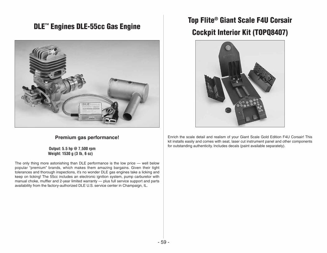
- 59 -
Premium gas performance!
Output: 5.5 hp @ 7,500 rpm Weight: 1530 g (3 lb, 6 oz)
The only thing more astonishing than DLE performance is the low price — well below popular “premium” brands, which makes them amazing bargains. Given their tight tolerances and thorough inspections, it’s no wonder DLE gas engines take a licking and keep on ticking! The 55cc includes an electronic ignition system, pump carburetor with manual choke, muffler and 2-year limited warranty — plus full service support and parts availability from the factory-authorized DLE U.S. service center in Champaign, IL.
Enrich the scale detail and realism of your Giant Scale Gold Edition F4U Corsair! This kit installs easily and comes with seat, laser cut instrument panel and other components for outstanding authenticity. Includes decals (paint available separately).
DLE™ Engines DLE-55cc Gas EngineTop Flite® Giant Scale F4U Corsair
Cockpit Interior Kit (TOPQ8407)