Embed Size (px)
Citation preview
48V DCDistribution
Rack
DOF159 MHz
Base Station
Channel Bank
Rack CR-5
FHPFilter
Duplexer
FHP Tx/Rx #1Motorola
FHP Tx/Rx #2Motorola
DVM6-45 MW
Repeater Rack CR-2
MAS Call Box Base Station
Rack CR-1
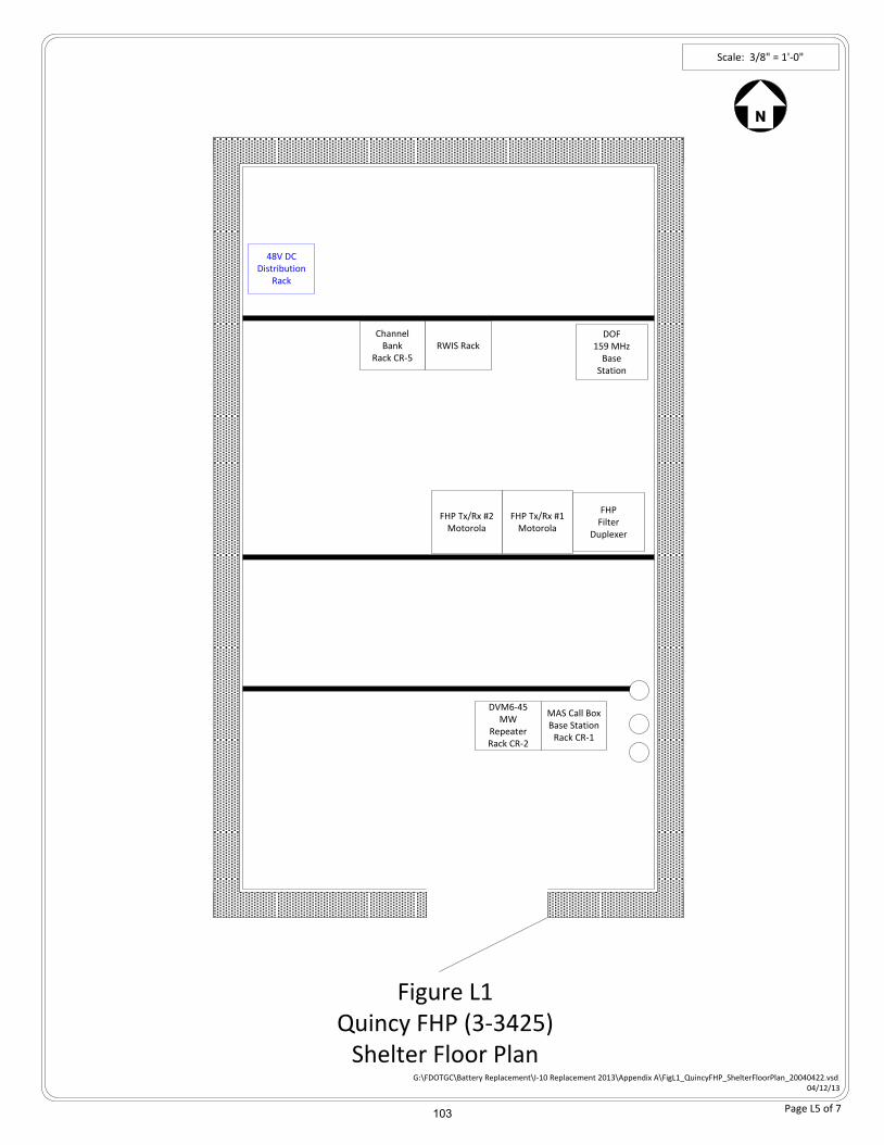
G:\FDOTGC\Battery Replacement\I-10 Replacement 2013\Appendix A\FigL1_QuincyFHP_ShelterFloorPlan_20040422.vsd04/12/13
Figure L1Quincy FHP (3-3425)
Shelter Floor Plan
Scale: 3/8" = 1'-0"
RWIS Rack
Page L5 of 7 103
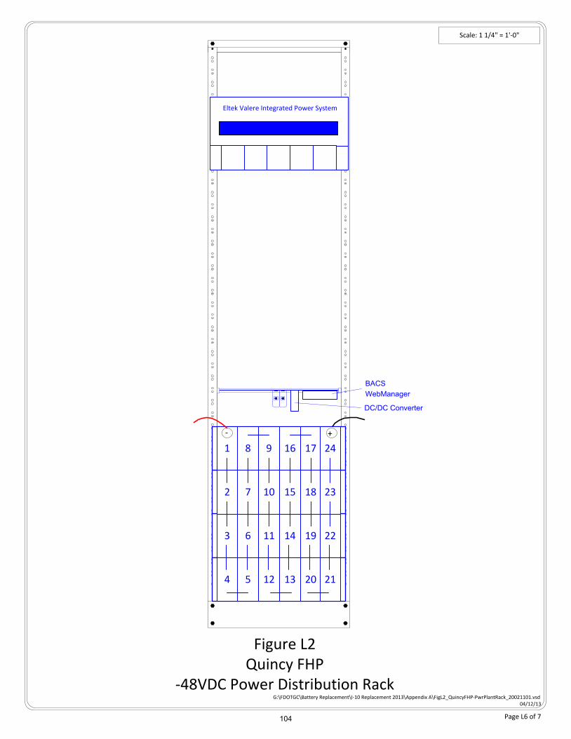
Scale: 1 1/4" = 1'-0"
Figure L2Quincy FHP
-48VDC Power Distribution Rack
Eltek Valere Integrated Power System
G:\FDOTGC\Battery Replacement\I-10 Replacement 2013\Appendix A\FigL2_QuincyFHP-PwrPlantRack_20021101.vsd04/12/13
Absolyte Battery Bank
Absolyte Battery Bank
Absolyte Battery Bank
Absolyte Battery Bank81 9 16 17 24
72 10 15 18 23
63 11 14 19 22
54 12 13 20 21
+-
Page L6 of 7
BACS
WebManager
DC/DC Converter
104
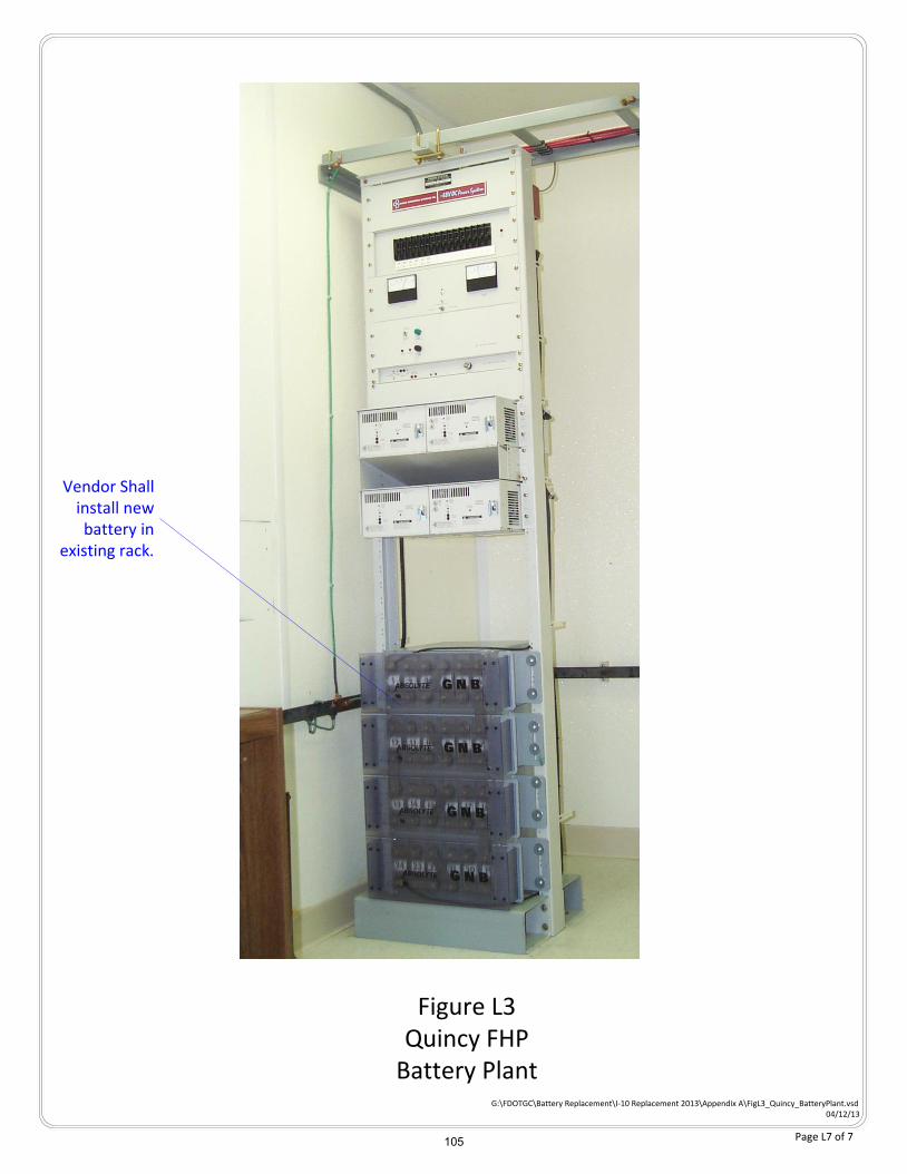
Figure L3Quincy FHP
Battery PlantG:\FDOTGC\Battery Replacement\I-10 Replacement 2013\Appendix A\FigL3_Quincy_BatteryPlant.vsd
04/12/13
Vendor Shall install new battery in
existing rack.
Page L7 of 7 105

FLORIDA DEPARTMENT OF TRANSPORTATION
I-10 BATTERY PLANT REPLACEMENT
Appendix M – Tallahassee FHP
106
FLORIDA DEPARTMENT OF TRANSPORTATION
I-10 BATTERY PLANT REPLACEMENT
Page M2 of 6
Appendix M – Table of Contents – Figures and Drawings
Figure M1 – Tallahassee FHP Shelter Floor Plan .................................................... M4 of 6
Figure M2 – Tallahassee FHP -48VDC Power Distribution Rack Profile .................. M5 of 6
Figure M3 – Tallahassee FHP Battery Plant Photo .................................................. M6 of 6
107
FLORIDA DEPARTMENT OF TRANSPORTATION
I-10 BATTERY PLANT REPLACEMENT
Page M3 of 6
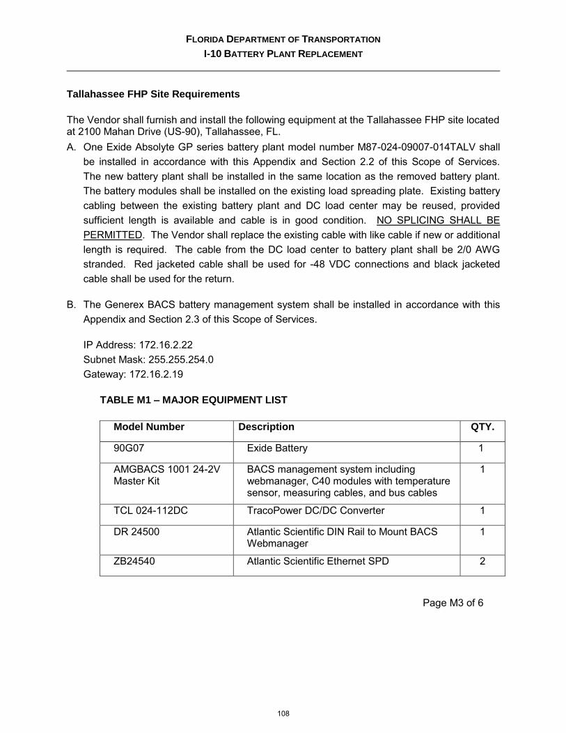
Tallahassee FHP Site Requirements
The Vendor shall furnish and install the following equipment at the Tallahassee FHP site located at 2100 Mahan Drive (US-90), Tallahassee, FL.
A. One Exide Absolyte GP series battery plant model number M87-024-09007-014TALV shall
be installed in accordance with this Appendix and Section 2.2 of this Scope of Services.
The new battery plant shall be installed in the same location as the removed battery plant.
The battery modules shall be installed on the existing load spreading plate. Existing battery
cabling between the existing battery plant and DC load center may be reused, provided
sufficient length is available and cable is in good condition. NO SPLICING SHALL BE
PERMITTED. The Vendor shall replace the existing cable with like cable if new or additional
length is required. The cable from the DC load center to battery plant shall be 2/0 AWG
stranded. Red jacketed cable shall be used for -48 VDC connections and black jacketed
cable shall be used for the return.
B. The Generex BACS battery management system shall be installed in accordance with this
Appendix and Section 2.3 of this Scope of Services.
IP Address: 172.16.2.22
Subnet Mask: 255.255.254.0
Gateway: 172.16.2.19
TABLE M1 – MAJOR EQUIPMENT LIST
Model Number Description QTY.
90G07 Exide Battery 1
AMGBACS 1001 24-2V Master Kit
BACS management system including webmanager, C40 modules with temperature sensor, measuring cables, and bus cables
1
TCL 024-112DC TracoPower DC/DC Converter 1
DR 24500 Atlantic Scientific DIN Rail to Mount BACS Webmanager
1
ZB24540 Atlantic Scientific Ethernet SPD 2
108
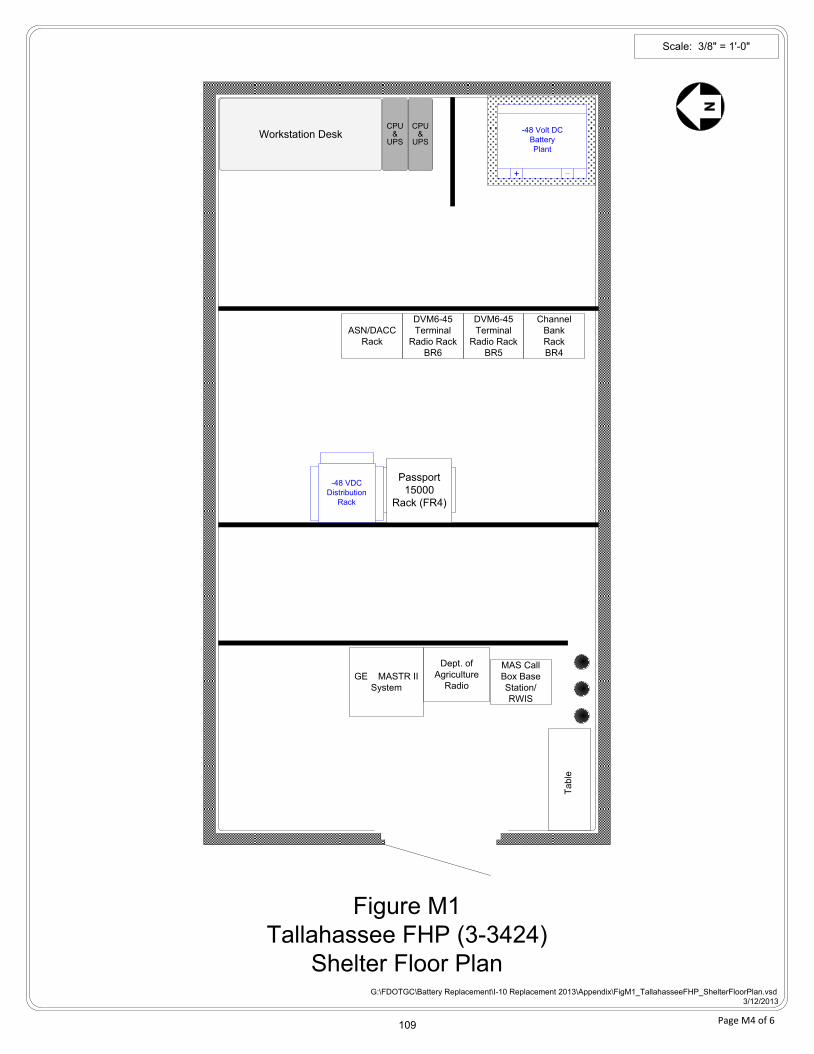
Figure M1
Tallahassee FHP (3-3424)
Shelter Floor PlanG:\FDOTGC\Battery Replacement\I-10 Replacement 2013\Appendix\FigM1_TallahasseeFHP_ShelterFloorPlan.vsd
3/12/2013
Scale: 3/8" = 1'-0"
GE MASTR II
System
Channel
Bank
Rack
BR4
DVM6-45
Terminal
Radio Rack
BR6
DVM6-45
Terminal
Radio Rack
BR5
MAS Call
Box Base
Station/
RWIS
Dept. of
Agriculture
Radio
Ta
ble
-48 Volt DC
Battery
Plant
+
Workstation DeskCPU
&UPS
CPU&
UPS
ASN/DACC
Rack
-48 VDC
Distribution
Rack
Passport
15000
Rack (FR4)
Page M4 of 6 109
G:\FDOTGC\Battery Replacement\I-10 Replacement 2013\Appendix A\FigM2_TallahasseeFHP_-48VDCPowerDistributionRack_20130109.vsd
04/12/13
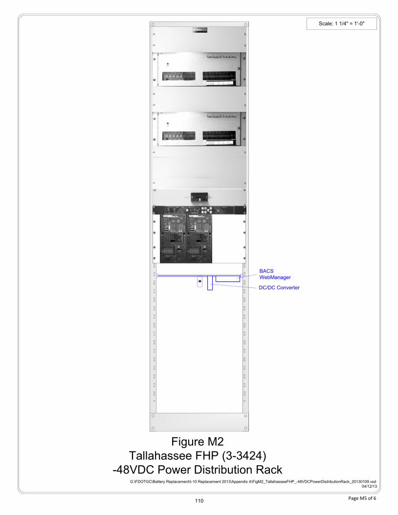
Scale: 1 1/4" = 1'-0"
Figure M2
Tallahassee FHP (3-3424)
-48VDC Power Distribution Rack
Page M5 of 6
BACS
WebManager
DC/DC Converter
110
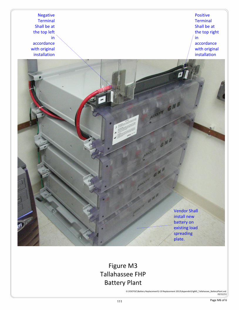
Figure M3Tallahassee FHP
Battery PlantG:\FDOTGC\Battery Replacement\I-10 Replacement 2013\Appendix\FigM3_Tallahassee_BatteryPlant.vsd
03/12/13
Vendor Shall install new battery on existing load spreading plate.
Positive Terminal Shall be at the top right in accordance with original installation
Negative Terminal
Shall be at the top left
in accordance
with original installation
Page M6 of 6 111

FLORIDA DEPARTMENT OF TRANSPORTATION
I-10 BATTERY PLANT REPLACEMENT
Appendix N – Monticello DOT
112
FLORIDA DEPARTMENT OF TRANSPORTATION
I-10 BATTERY PLANT REPLACEMENT
Page N2 of 7
Appendix N – Table of Contents – Figures and Drawings
Figure N1 – Monticello DOT Shelter Floor Plan........................................................ N5 of 7
Figure N2 – Monticello DOT -48VDC Power Distribution Rack Profile ...................... N6 of 7
Figure N3 – Monticello DOT Battery Plant Photo ..................................................... N7 of 7
113
FLORIDA DEPARTMENT OF TRANSPORTATION
I-10 BATTERY PLANT REPLACEMENT
Page N3 of 7
Monticello DOT Site Requirements
The Vendor shall furnish and install the following equipment at the Monticello DOT site located 0.5 miles north of US-19 and I-10 interchange at maintenance yard in Monticello, FL.
A. One Exide Absolyte GP series battery plant model number M87-024-05007-R19AALV shall
be installed in accordance with this Appendix and Section 2.2 of this Scope of Services.
The new battery plant shall be installed in the same location as the removed battery plant.
The Vendor shall replace the existing cable with 1/0 AWG stranded. Red jacketed cable
shall be used for -48 VDC connections and black jacketed cable shall be used for the return.
B. The Generex BACS battery management system shall be installed in accordance with this
Appendix and Section 2.3 of this Scope of Services.
IP Address: 172.16.68.22
Subnet Mask: 255.255.254.0
Gateway: 172.16.68.19
C. One Eltek Valere integrated power system shall be installed in accordance with this
Appendix and Section 2.3 of this Scope of Services.
IP Address: 172.16.68.20
Subnet Mask: 255.255.254.0
Gateway: 172.16.68.19
114
FLORIDA DEPARTMENT OF TRANSPORTATION
I-10 BATTERY PLANT REPLACEMENT
Page N4 of 7
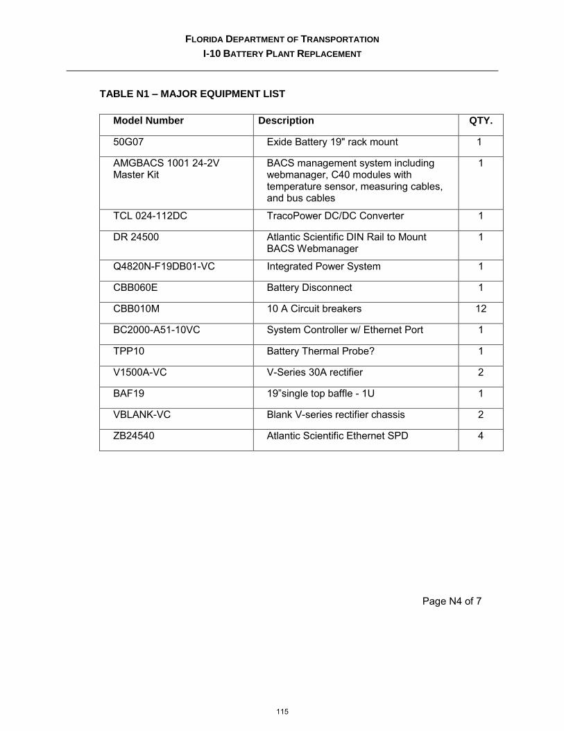
TABLE N1 – MAJOR EQUIPMENT LIST
Model Number Description QTY.
50G07 Exide Battery 19" rack mount 1
AMGBACS 1001 24-2V Master Kit
BACS management system including webmanager, C40 modules with temperature sensor, measuring cables, and bus cables
1
TCL 024-112DC TracoPower DC/DC Converter 1
DR 24500 Atlantic Scientific DIN Rail to Mount BACS Webmanager
1
Q4820N-F19DB01-VC Integrated Power System 1
CBB060E Battery Disconnect 1
CBB010M 10 A Circuit breakers 12
BC2000-A51-10VC System Controller w/ Ethernet Port 1
TPP10 Battery Thermal Probe? 1
V1500A-VC V-Series 30A rectifier 2
BAF19 19”single top baffle - 1U 1
VBLANK-VC Blank V-series rectifier chassis 2
ZB24540 Atlantic Scientific Ethernet SPD 4
115
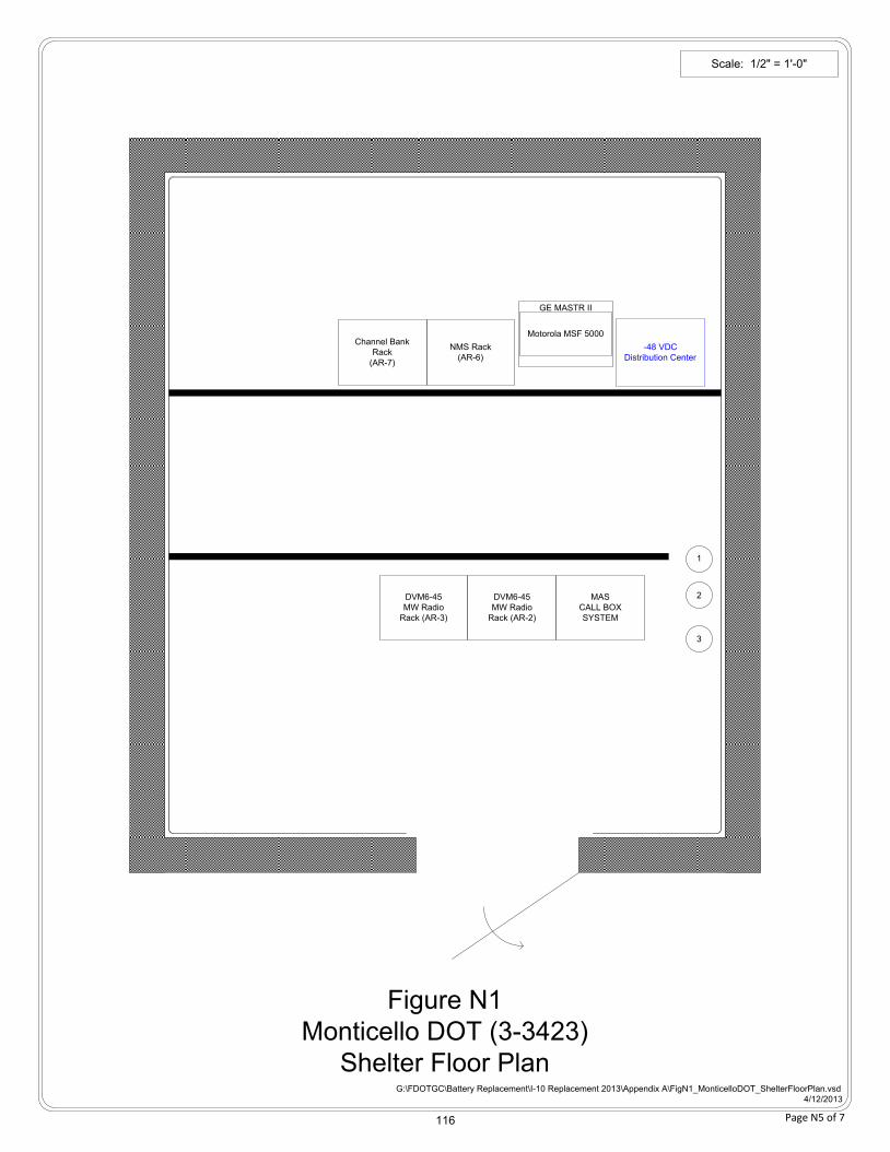
G:\FDOTGC\Battery Replacement\I-10 Replacement 2013\Appendix A\FigN1_MonticelloDOT_ShelterFloorPlan.vsd
4/12/2013
Figure N1
Monticello DOT (3-3423)
Shelter Floor Plan
Scale: 1/2" = 1'-0"
-48 VDC
Distribution Center
Motorola MSF 5000
DVM6-45
MW Radio
Rack (AR-2)
DVM6-45
MW Radio
Rack (AR-3)
Channel Bank
Rack
(AR-7)
NMS Rack
(AR-6)
3
2
1
MAS
CALL BOX
SYSTEM
GE MASTR II
Page N5 of 7 116
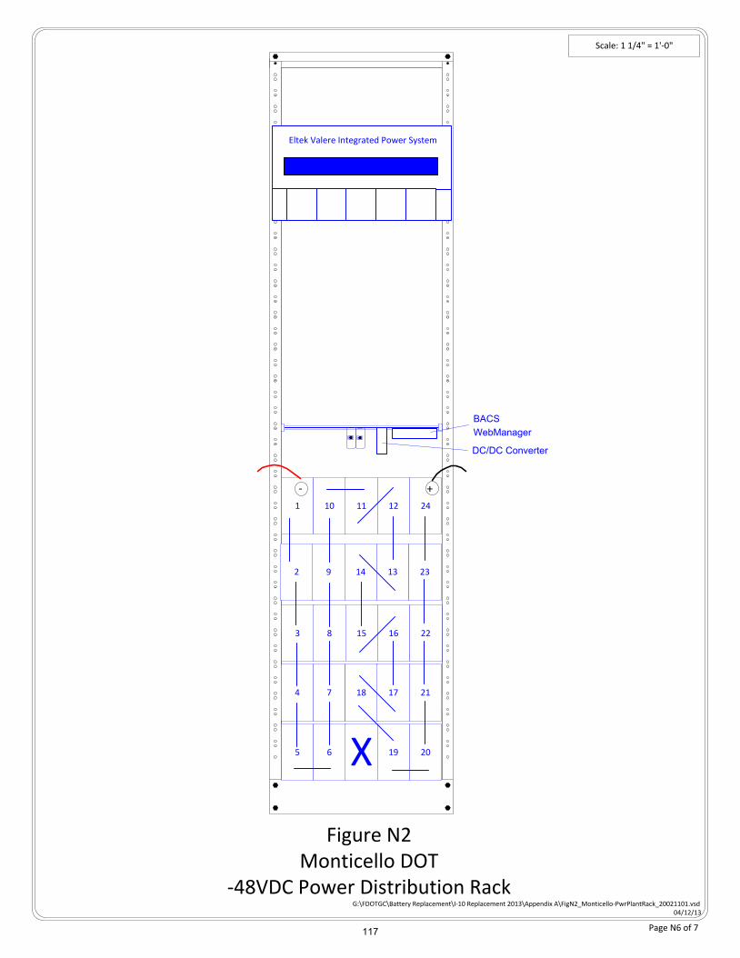
Scale: 1 1/4" = 1'-0"
Figure N2Monticello DOT
-48VDC Power Distribution Rack
Eltek Valere Integrated Power System
G:\FDOTGC\Battery Replacement\I-10 Replacement 2013\Appendix A\FigN2_Monticello-PwrPlantRack_20021101.vsd04/12/13
1 10 11 12 24
2 9 14 13 23
+
3 8 15 16 22
4 7 18 17 21
5 6 X 19 20
-
Page N6 of 7
BACS
WebManager
DC/DC Converter
117
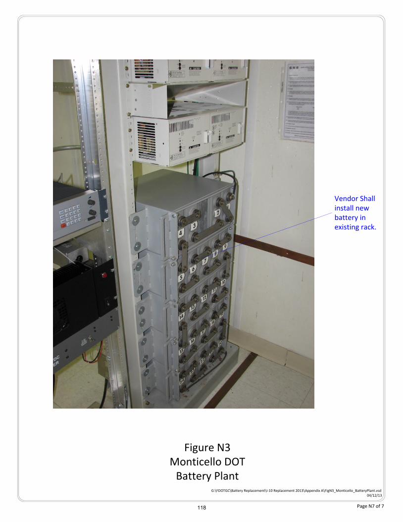
Figure N3Monticello DOT
Battery PlantG:\FDOTGC\Battery Replacement\I-10 Replacement 2013\Appendix A\FigN3_Monticello_BatteryPlant.vsd
04/12/13
Vendor Shall install new battery in existing rack.
Page N7 of 7 118

FLORIDA DEPARTMENT OF TRANSPORTATION
I-10 BATTERY PLANT REPLACEMENT
Appendix O – Greenville
119
FLORIDA DEPARTMENT OF TRANSPORTATION
I-10 BATTERY PLANT REPLACEMENT
Page O2 of 7
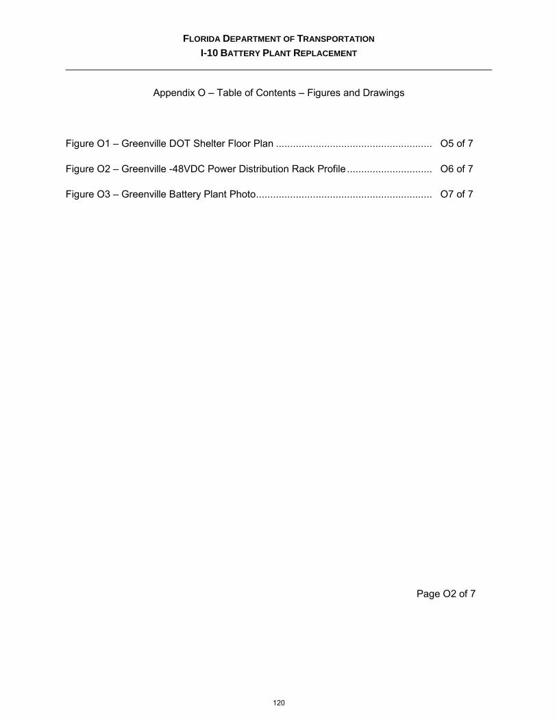
Appendix O – Table of Contents – Figures and Drawings
Figure O1 – Greenville DOT Shelter Floor Plan ....................................................... O5 of 7
Figure O2 – Greenville -48VDC Power Distribution Rack Profile .............................. O6 of 7
Figure O3 – Greenville Battery Plant Photo .............................................................. O7 of 7
120
FLORIDA DEPARTMENT OF TRANSPORTATION
I-10 BATTERY PLANT REPLACEMENT
Page O3 of 7
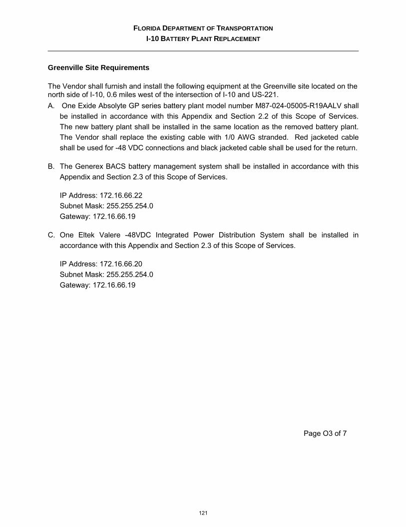
Greenville Site Requirements
The Vendor shall furnish and install the following equipment at the Greenville site located on the north side of I-10, 0.6 miles west of the intersection of I-10 and US-221.
A. One Exide Absolyte GP series battery plant model number M87-024-05005-R19AALV shall
be installed in accordance with this Appendix and Section 2.2 of this Scope of Services.
The new battery plant shall be installed in the same location as the removed battery plant.
The Vendor shall replace the existing cable with 1/0 AWG stranded. Red jacketed cable
shall be used for -48 VDC connections and black jacketed cable shall be used for the return.
B. The Generex BACS battery management system shall be installed in accordance with this
Appendix and Section 2.3 of this Scope of Services.
IP Address: 172.16.66.22
Subnet Mask: 255.255.254.0
Gateway: 172.16.66.19
C. One Eltek Valere -48VDC Integrated Power Distribution System shall be installed in
accordance with this Appendix and Section 2.3 of this Scope of Services.
IP Address: 172.16.66.20
Subnet Mask: 255.255.254.0
Gateway: 172.16.66.19
121

FLORIDA DEPARTMENT OF TRANSPORTATION
I-10 BATTERY PLANT REPLACEMENT
Page O4 of 7
TABLE O1 – MAJOR EQUIPMENT LIST
Model Number Description QTY.
50G05 Exide Battery 19" rack mount 1
AMGBACS 1001 24-2V Master Kit
BACS management system including webmanager, C40 modules with temperature sensor, measuring cables, and bus cables
1
TCL 024-112DC TracoPower DC/DC Converter 1
DR 24500 Atlantic Scientific DIN Rail to Mount BACS Webmanager
1
Q4820N-F19DB01-VC Integrated Power System 1
CBB060E Battery Disconnect 1
CBB010M 10 A Circuit breakers 6
BC2000-A51-10VC System Controller w/ Ethernet Port 1
TPP10 Battery Thermal Probe? 1
V1500A-VC V-Series 30A rectifier 2
BAF19 19”single top baffle - 1U 1
VBLANK-VC Blank V-series rectifier chassis 2
ZB24540 Atlantic Scientific Ethernet SPD 4
122
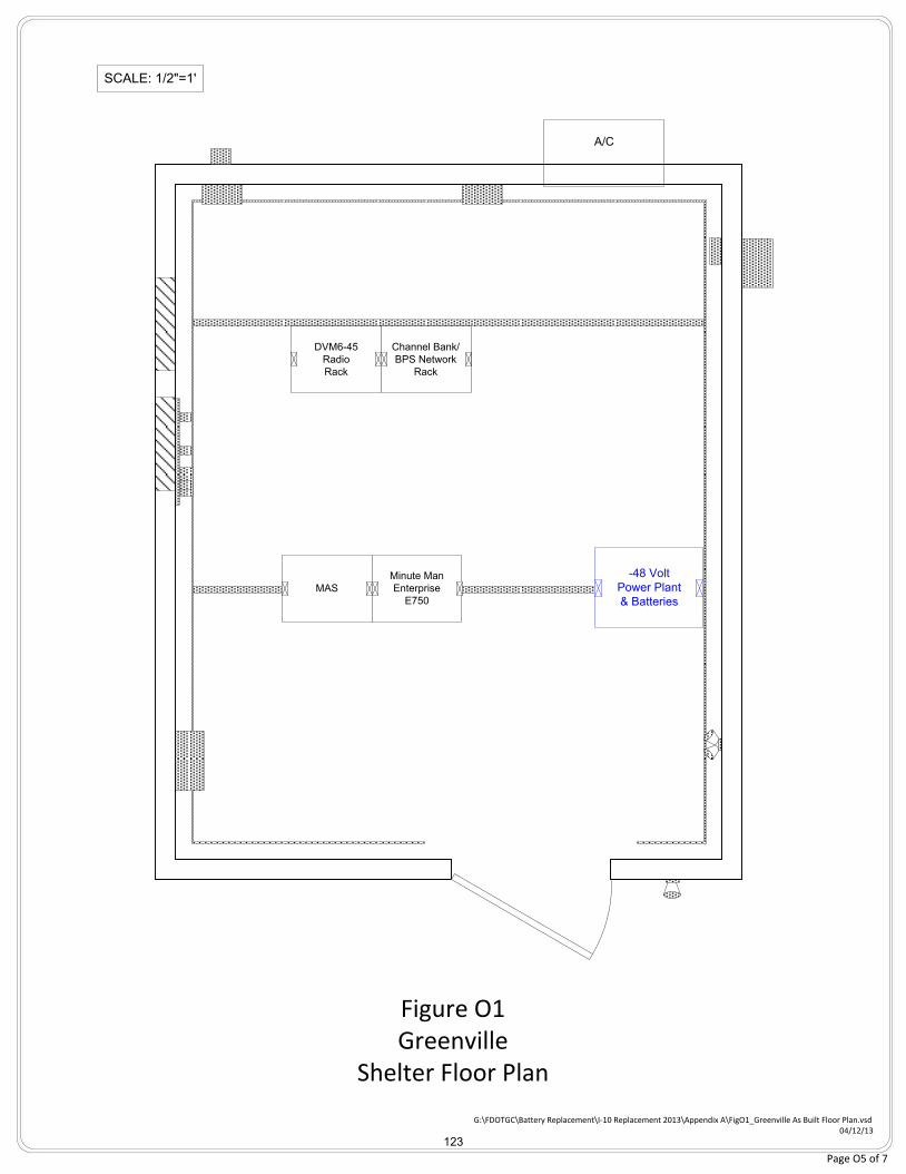
SCALE: 1/2"=1'
MAS
Minute Man
Enterprise
E750
A/C
Channel Bank/
BPS Network
Rack
DVM6-45
Radio
Rack
-48 Volt
Power Plant
& Batteries
Figure O1Greenville
Shelter Floor Plan
G:\FDOTGC\Battery Replacement\I-10 Replacement 2013\Appendix A\FigO1_Greenville As Built Floor Plan.vsd04/12/13
Page O5 of 7
123
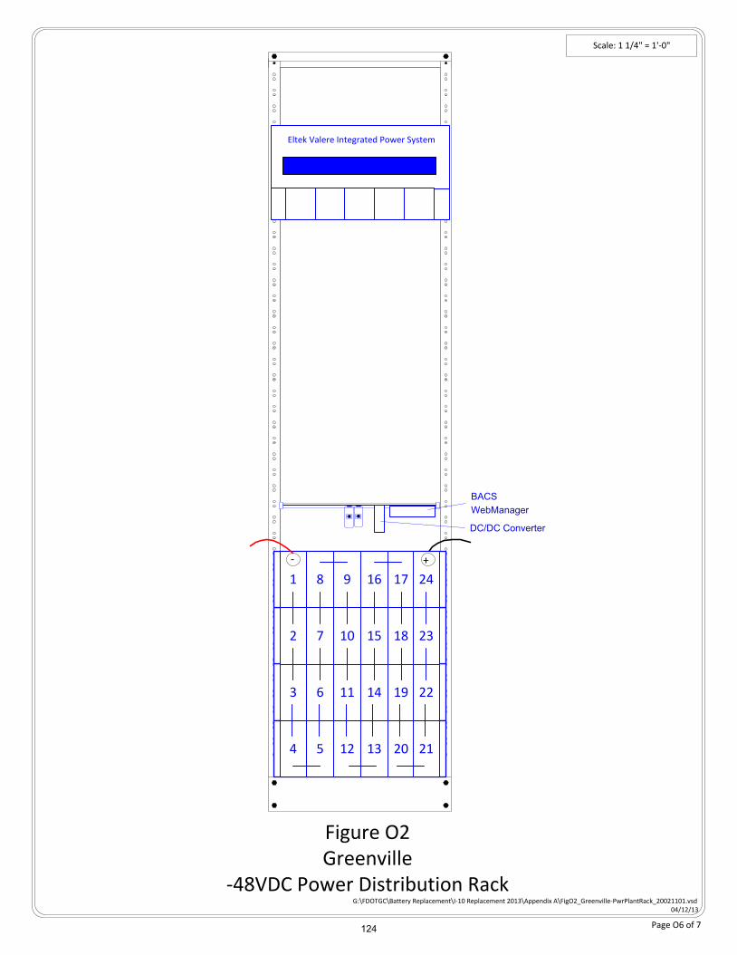
Scale: 1 1/4" = 1'-0"
Figure O2Greenville
-48VDC Power Distribution Rack
Eltek Valere Integrated Power System
G:\FDOTGC\Battery Replacement\I-10 Replacement 2013\Appendix A\FigO2_Greenville-PwrPlantRack_20021101.vsd04/12/13
Absolyte Battery Bank
Absolyte Battery Bank
Absolyte Battery Bank
Absolyte Battery Bank81 9 16 17 24
72 10 15 18 23
63 11 14 19 22
54 12 13 20 21
+-
Page O6 of 7
BACS
WebManager
DC/DC Converter
124
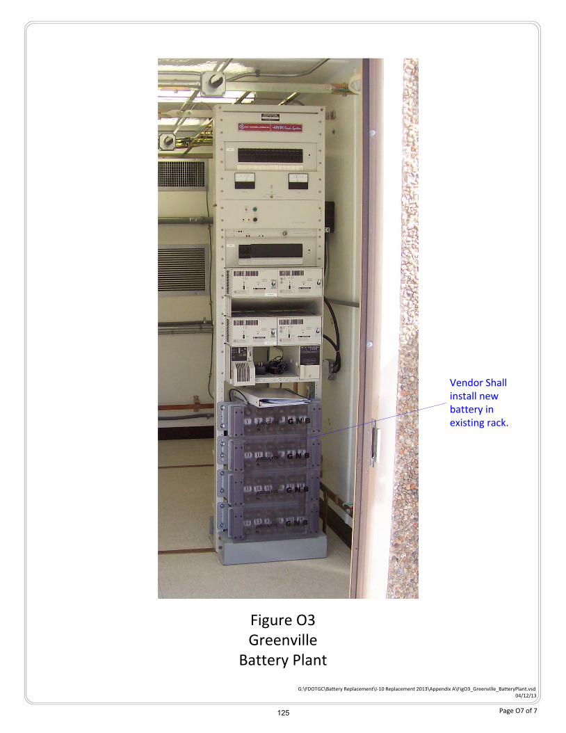
Figure O3Greenville
Battery Plant
G:\FDOTGC\Battery Replacement\I-10 Replacement 2013\Appendix A\FigO3_Greenville_BatteryPlant.vsd04/12/13
Vendor Shall install new battery in existing rack.
Page O7 of 7 125

FLORIDA DEPARTMENT OF TRANSPORTATION
I-10 BATTERY PLANT REPLACEMENT
Appendix P – Jacksonville FHP
126
FLORIDA DEPARTMENT OF TRANSPORTATION
I-10 BATTERY PLANT REPLACEMENT
Page P2 of 6
Appendix P – Table of Contents – Figures and Drawings
Figure P1 – Jacksonville FHP Shelter Floor Plan ..................................................... P4 of 6
Figure P2 – Jacksonville FHP -48VDC Power Distribution Rack Profile ................... P5 of 6
Figure P3 – Jacksonville FHP Battery Plant Photo……………………………………… P6 of 6
127


![valere smps gs150a[1]](https://img.pdfslide.us/doc/110x75/553c89db550346a43f8b4a48/valere-smps-gs150a1.jpg)