Embed Size (px)
DESCRIPTION
Ethernet Controller Install Guide
Citation preview

Page 1 of 22 Version 1.0
DO6000000231 April, 2007
BC2000, NIC-Series, XC-Series
Controller
Telnet Feature
24 x7 Installation and Technical Support
1-866-240-6614
Page 2 of 22 Version 1.0
DO6000000231 April, 2007
1 Purpose The purpose of this manual is to guide the user in connecting to the controller via Telnet, and issuing commands to the controller.
This document assumes that the user has already set the controller up onto a network and the controller has a known, proper IP address. For more information on connecting the controller to a network see “D0600000228 – BC2000 – JC2000-Series Web Interface”.
2 Connecting to the controller This section will guide you through establishing a Telnet connection with the controller. The example used in this manual, PuTTY, is available on the CD that comes with the controller unit. Any Telnet program will work in place of PuTTY.
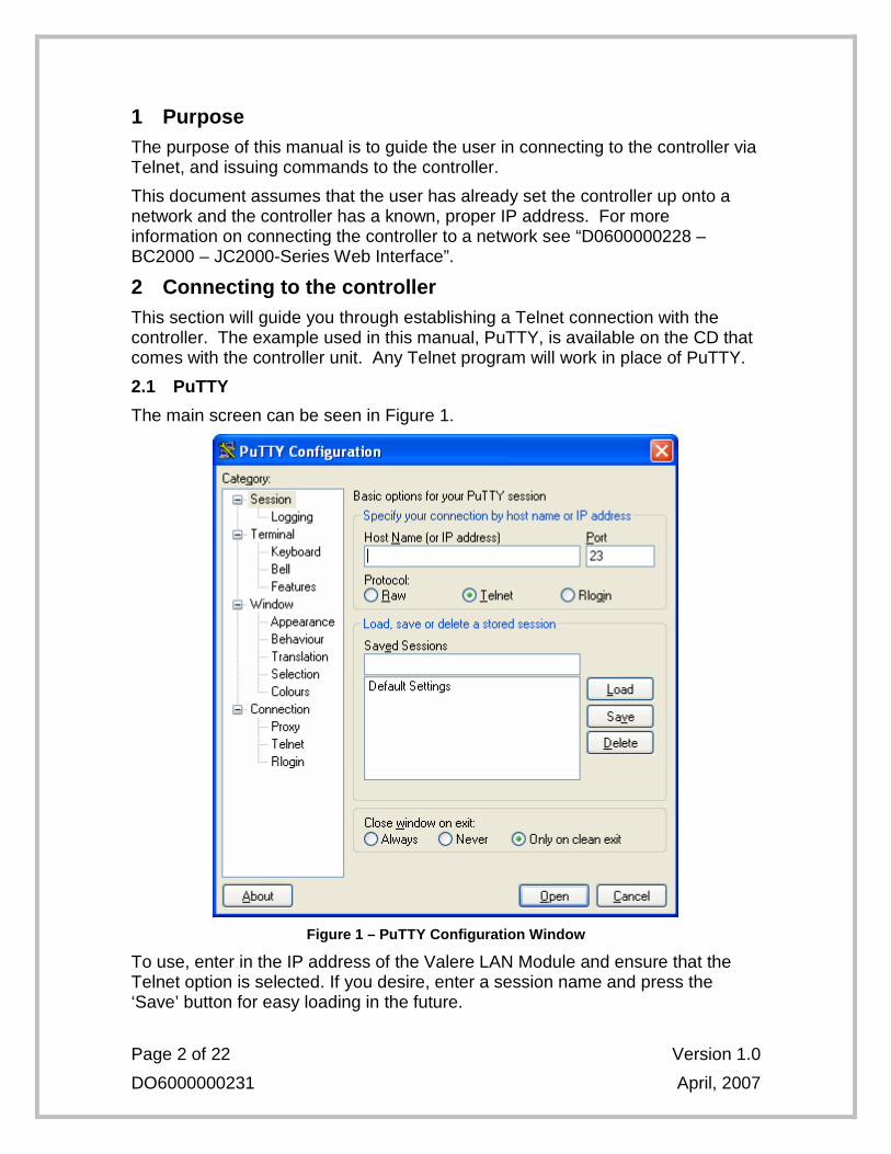
2.1 PuTTY
The main screen can be seen in Figure 1.
Figure 1 – PuTTY Configuration Window
To use, enter in the IP address of the Valere LAN Module and ensure that the Telnet option is selected. If you desire, enter a session name and press the ‘Save’ button for easy loading in the future.
Page 3 of 22 Version 1.0
DO6000000231 April, 2007
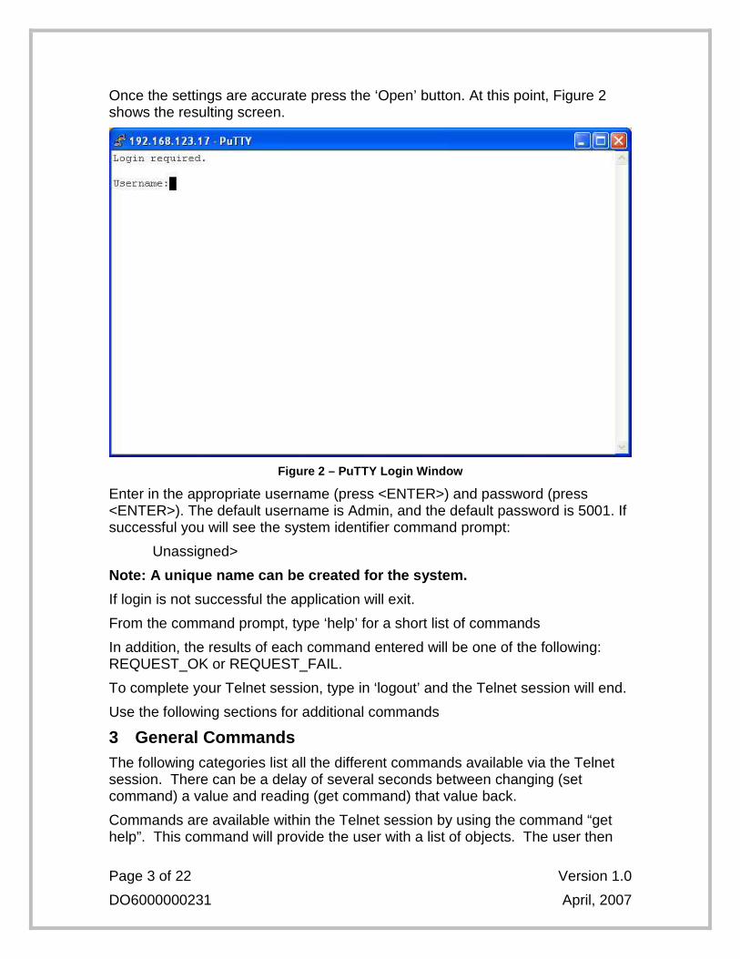
Once the settings are accurate press the ‘Open’ button. At this point, Figure 2 shows the resulting screen.
Figure 2 – PuTTY Login Window
Enter in the appropriate username (press <ENTER>) and password (press <ENTER>). The default username is Admin, and the default password is 5001. If successful you will see the system identifier command prompt:
Unassigned>
Note: A unique name can be created for the system.
If login is not successful the application will exit.
From the command prompt, type ‘help’ for a short list of commands
In addition, the results of each command entered will be one of the following: REQUEST_OK or REQUEST_FAIL.
To complete your Telnet session, type in ‘logout’ and the Telnet session will end.
Use the following sections for additional commands
3 General Commands The following categories list all the different commands available via the Telnet session. There can be a delay of several seconds between changing (set command) a value and reading (get command) that value back.
Commands are available within the Telnet session by using the command “get help”. This command will provide the user with a list of objects. The user then
Page 4 of 22 Version 1.0
DO6000000231 April, 2007
can use the object in the command “get object help” for a list of tokens for that object.
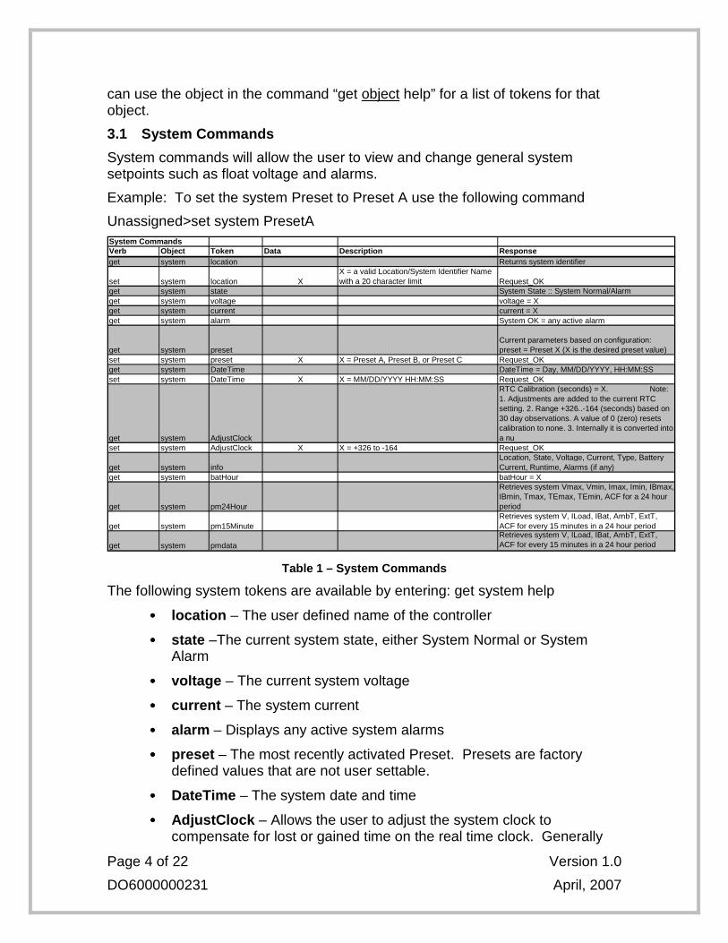
3.1 System Commands
System commands will allow the user to view and change general system setpoints such as float voltage and alarms.
Example: To set the system Preset to Preset A use the following command
Unassigned>set system PresetA System CommandsVerb Object Token Data Description Responseget system location Returns system identifier
set system location XX = a valid Location/System Identifier Name with a 20 character limit Request_OK
get system state System State :: System Normal/Alarmget system voltage voltage = Xget system current current = Xget system alarm System OK = any active alarm
get system presetCurrent parameters based on configuration: preset = Preset X (X is the desired preset value)
set system preset X X = Preset A, Preset B, or Preset C Request_OKget system DateTime DateTime = Day, MM/DD/YYYY, HH:MM:SSset system DateTime X X = MM/DD/YYYY HH:MM:SS Request_OK
get system AdjustClock
RTC Calibration (seconds) = X. Note: 1. Adjustments are added to the current RTC setting. 2. Range +326..-164 (seconds) based on 30 day observations. A value of 0 (zero) resets calibration to none. 3. Internally it is converted into a nu
set system AdjustClock X X = +326 to -164 Request_OK
get system infoLocation, State, Voltage, Current, Type, Battery Current, Runtime, Alarms (if any)
get system batHour batHour = X
get system pm24Hour
Retrieves system Vmax, Vmin, Imax, Imin, IBmax, IBmin, Tmax, TEmax, TEmin, ACF for a 24 hour period
get system pm15MinuteRetrieves system V, ILoad, IBat, AmbT, ExtT, ACF for every 15 minutes in a 24 hour period
get system pmdataRetrieves system V, ILoad, IBat, AmbT, ExtT, ACF for every 15 minutes in a 24 hour period
Table 1 – System Commands
The following system tokens are available by entering: get system help
•••• location – The user defined name of the controller
•••• state –The current system state, either System Normal or System Alarm
•••• voltage – The current system voltage
•••• current – The system current
•••• alarm – Displays any active system alarms
•••• preset – The most recently activated Preset. Presets are factory defined values that are not user settable.
•••• DateTime – The system date and time
•••• AdjustClock – Allows the user to adjust the system clock to compensate for lost or gained time on the real time clock. Generally
Page 5 of 22 Version 1.0
DO6000000231 April, 2007
the system runs for a 30 day period before the clocks are analyzed for lost or gained time.
•••• Info – Displays all system information
•••• batHour – Displays the battery hour. This feature is obsolete.
•••• pm24Hour – Displays the load history everyday for the past three (3) years
•••• pm15Minute – Displays the load history every 15 minutes for the last 24 hours
•••• pmdata – Displays the load history for every 15 minutes for the last 24 hours
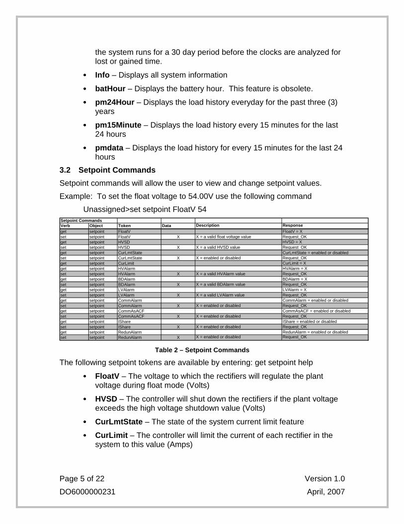
3.2 Setpoint Commands
Setpoint commands will allow the user to view and change setpoint values.
Example: To set the float voltage to 54.00V use the following command
Unassigned>set setpoint FloatV 54 Setpoint CommandsVerb Object Token Data Description Responseget setpoint FloatV FloatV = Xset setpoint FloatV X X = a valid float voltage value Request_OKget setpoint HVSD HVSD = Xset setpoint HVSD X X = a valid HVSD value Request_OKget setpoint CurLmtState CurLmtState = enabled or disabledset setpoint CurLmtState X X = enabled or disabled Request_OKget setpoint CurLimit CurLimit = Xget setpoint HVAlarm HVAlarm = Xset setpoint HVAlarm X X = a valid HVAlarm value Request_OKget setpoint BDAlarm BDAlarm = Xset setpoint BDAlarm X X = a valid BDAlarm value Request_OKget setpoint LVAlarm LVAlarm = Xset setpoint LVAlarm X X = a valid LVAlarm value Request_OKget setpoint CommAlarm CommAlarm = enabled or disabledset setpoint CommAlarm X X = enabled or disabled Request_OKget setpoint CommAsACF CommAsACF = enabled or disabledset setpoint CommAsACF X X = enabled or disabled Request_OKget setpoint IShare IShare = enabled or disabledset setpoint IShare X X = enabled or disabled Request_OKget setpoint RedunAlarm RedunAlarm = enabled or disabledset setpoint RedunAlarm X X = enabled or disabled Request_OK
Table 2 – Setpoint Commands
The following setpoint tokens are available by entering: get setpoint help
•••• FloatV – The voltage to which the rectifiers will regulate the plant voltage during float mode (Volts)
•••• HVSD – The controller will shut down the rectifiers if the plant voltage exceeds the high voltage shutdown value (Volts)
•••• CurLmtState – The state of the system current limit feature
•••• CurLimit – The controller will limit the current of each rectifier in the system to this value (Amps)
Page 6 of 22 Version 1.0
DO6000000231 April, 2007
•••• HVAlarm – The controller will issue a high voltage alarm if the plant voltage exceeds this value (Volts)
•••• BDAlarm – The controller will issue a battery-on-discharge alarm if the plant voltage falls below this value (Volts)
•••• LVAlarm – The controller will issue a low voltage alarm if the plant voltage falls below this value (Volts)
•••• CommAlarm – An alarm is set if any rectifier either stops communicating or is removed from the shelf. User action is required to clear the alarm from the front display.
•••• CommAsACF – Associates an AC failure alarm with the removal of a rectifier. This is most useful for a loss of AC power to all rectifiers.
•••• IShare – Displays the state of the current share (IShare) alarm. An alarm is set if the output current of any rectifier exceeds current sharing tolerances.
•••• RedunAlarm – Displays the state of the system redundancy (N+1) alarm. An alarm is set if the number of installed rectifiers will not support N+1 redundancy required by the load.
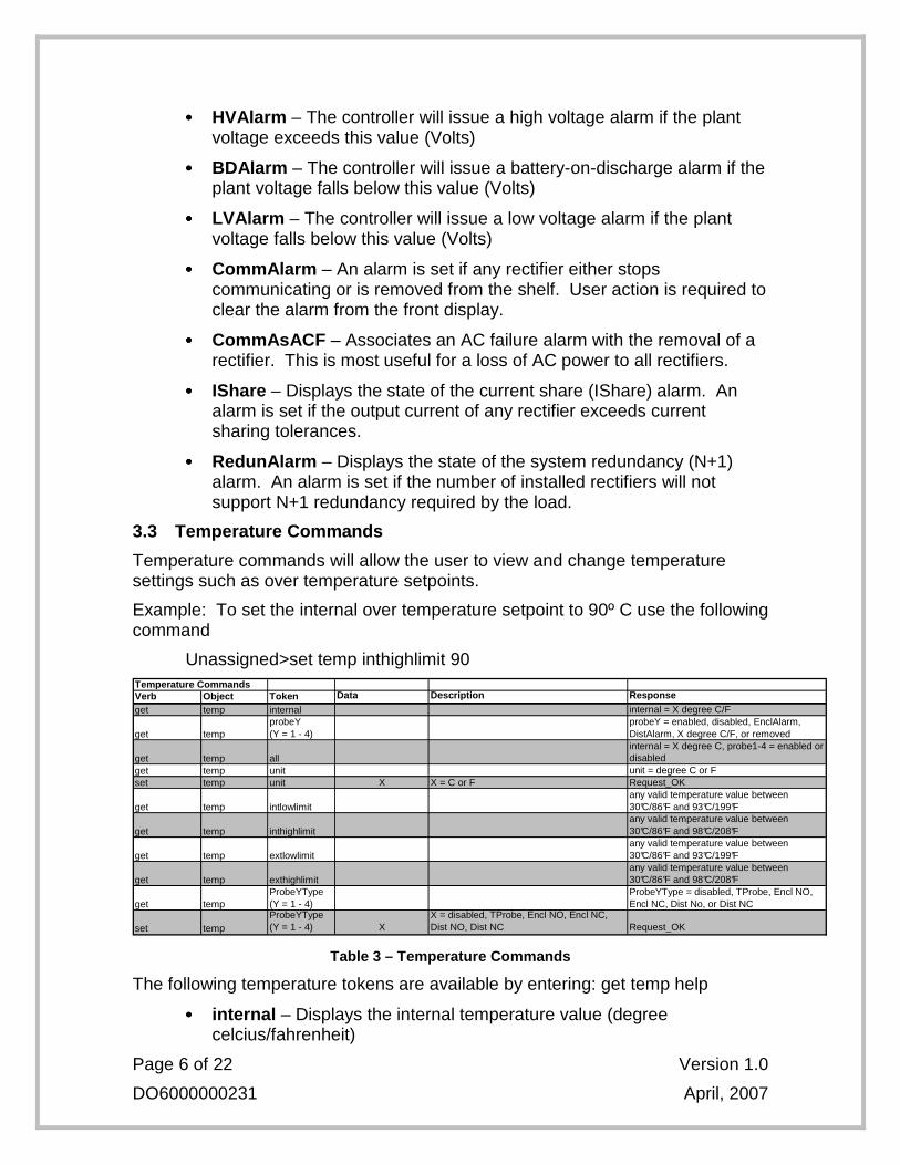
3.3 Temperature Commands
Temperature commands will allow the user to view and change temperature settings such as over temperature setpoints.
Example: To set the internal over temperature setpoint to 90º C use the following command
Unassigned>set temp inthighlimit 90 Temperature CommandsVerb Object Token Data Description Response
get temp internal internal = X degree C/F
get tempprobeY (Y = 1 - 4)
probeY = enabled, disabled, EnclAlarm, DistAlarm, X degree C/F, or removed
get temp allinternal = X degree C, probe1-4 = enabled or disabled
get temp unit unit = degree C or Fset temp unit X X = C or F Request_OK
get temp intlowlimitany valid temperature value between 30°C/86°F and 93°C/199°F
get temp inthighlimitany valid temperature value between 30°C/86°F and 98°C/208°F
get temp extlowlimitany valid temperature value between 30°C/86°F and 93°C/199°F
get temp exthighlimitany valid temperature value between 30°C/86°F and 98°C/208°F
get tempProbeYType (Y = 1 - 4)
ProbeYType = disabled, TProbe, Encl NO, Encl NC, Dist No, or Dist NC
set tempProbeYType (Y = 1 - 4) X
X = disabled, TProbe, Encl NO, Encl NC, Dist NO, Dist NC Request_OK
Table 3 – Temperature Commands
The following temperature tokens are available by entering: get temp help
•••• internal – Displays the internal temperature value (degree celcius/fahrenheit)
Page 7 of 22 Version 1.0
DO6000000231 April, 2007
•••• probeY – (Y = 1 - 4) Displays the external temperature values for selected probes 1, 2, 3, or 4 (degree celcius/fahrenheit)
•••• all – Displays all the external temperature values for probes 1 to 4 (degree celcius/fahrenheit)
•••• unit – The temperature unit (C or F) used for all temperature setpoints
•••• intlowlimit – The internal temperature value at which the controller will release an over temperature alarm
•••• inthighlimit – The internal temperature value at which the controller will trigger an over temperature alarm
•••• extlowlimit – The external temperature value at which the controller will release an over temperature alarm
•••• exthighlimit – The external temperature value at which the controller will trigger an over temperature alarm
•••• ProbeYType – (Y = 1 - 4) The type of the indicated input port: Probe1Type, Probe2Type, Probe3Type, or Probe4Type
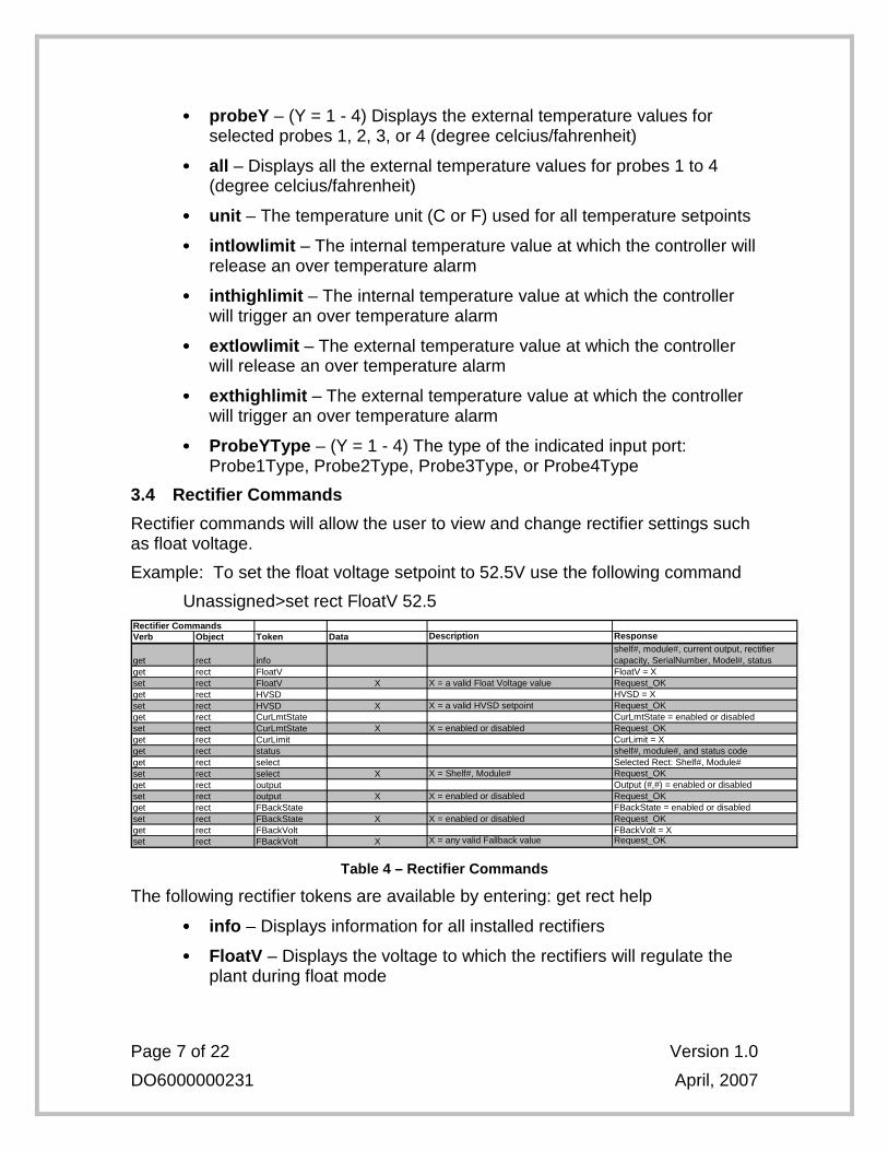
3.4 Rectifier Commands
Rectifier commands will allow the user to view and change rectifier settings such as float voltage.
Example: To set the float voltage setpoint to 52.5V use the following command
Unassigned>set rect FloatV 52.5 Rectifier CommandsVerb Object Token Data Description Response
get rect infoshelf#, module#, current output, rectifier capacity, SerialNumber, Model#, status
get rect FloatV FloatV = Xset rect FloatV X X = a valid Float Voltage value Request_OKget rect HVSD HVSD = Xset rect HVSD X X = a valid HVSD setpoint Request_OKget rect CurLmtState CurLmtState = enabled or disabledset rect CurLmtState X X = enabled or disabled Request_OKget rect CurLimit CurLimit = Xget rect status shelf#, module#, and status codeget rect select Selected Rect: Shelf#, Module#set rect select X X = Shelf#, Module# Request_OKget rect output Output (#,#) = enabled or disabledset rect output X X = enabled or disabled Request_OKget rect FBackState FBackState = enabled or disabledset rect FBackState X X = enabled or disabled Request_OKget rect FBackVolt FBackVolt = Xset rect FBackVolt X X = any valid Fallback value Request_OK
Table 4 – Rectifier Commands
The following rectifier tokens are available by entering: get rect help
•••• info – Displays information for all installed rectifiers
•••• FloatV – Displays the voltage to which the rectifiers will regulate the plant during float mode
Page 8 of 22 Version 1.0
DO6000000231 April, 2007
•••• HVSD – The controller will shutdown the rectifiers if the plant voltage exceeds this setpoint
•••• CurLmtState – Displays the state of the rectifier current limit feature
•••• CurLimit – The controller will limit the current of each rectifier to the current limit value
•••• status – The status code of all rectifiers installed
•••• select – The shelf# and module# of the rectifier currently selected for disabling the output
•••• output – The output status of the rectifier selected either enabled or disabled. Warning: Disabling the outputs of all rectifiers can cause loss of communication with the controller.
•••• FBackState – The status of the fallback feature. Fallback provides a safe voltage to which the rectifiers will output when they lose communication with the controller for more than one minute.
•••• FBackVolt – The voltage setpoint for the fallback feature
3.5 Low Voltage Disconnect (LVD) Commands
LVD commands will allow the user to view and change LVD settings such as LVD open voltage. An LVD contactor must be installed in the system for the commands to be useful.
Example: To set the LVD open voltage for disconnect1 to 42 V DC use the following command
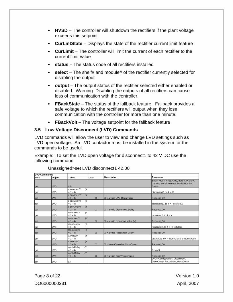
Unassigned>set LVD disconnect1 42.00 LVD CommandsVerb Object Token Data Description Response
get LVD info
Encl#, Mod#, Cnt1, Cnt2, Batt-V, Plant-V, Current, Serial Number, Model Number, Status
get LVDdisconnectY (Y = 1 - 4) disconnect1 to 4 = X
set LVDdisconnectY (Y = 1 - 4) X X = a valid LVD Open value Request_OK
get LVDdiscoDelayY (Y = 1 - 4) discoDelay1 to 4 = HH:MM:SS
set LVDdiscoDelayY (Y = 1 - 4) X X = a valid Disconnect Delay Request_OK
get LVDreconnectY (Y = 1 - 4) reconnect1 to 4 = X
set LVDreconnectY (Y = 1 - 4) X X = a valid reconnect value (V) Request_OK
get LVDrecoDelayY (Y = 1 - 4) recoDelay1 to 4 = HH:MM:SS
set LVDrecoDelayY (Y = 1 - 4) X X = a valid Reconnect Delay Request_OK
get LVDauxinputY (Y = 1 - 4) auxinput1 to 4 = NormClose or NormOpen
set LVDauxinputY (Y = 1 - 4) X X = NormClosed or NormOpen Request_OK
get LVDcontYRelay (Y = 1 - 4) Relay X
set LVDcontYRelay (Y = 1 - 4) X X = a valid contYRelay value Request_OK
get LVD allLVD# Configuration: Disconnect, DiscoDelay, Reconnect, RecoDelay
Page 9 of 22 Version 1.0
DO6000000231 April, 2007
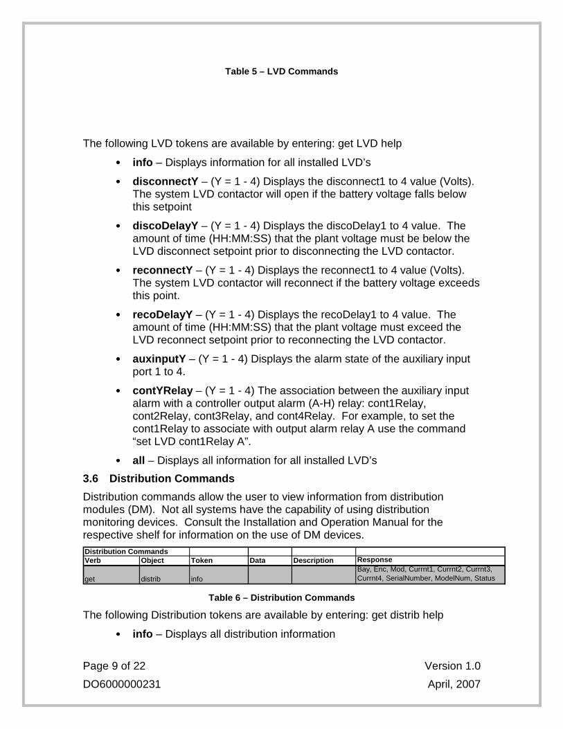
Table 5 – LVD Commands
The following LVD tokens are available by entering: get LVD help
•••• info – Displays information for all installed LVD’s
•••• disconnectY – (Y = 1 - 4) Displays the disconnect1 to 4 value (Volts). The system LVD contactor will open if the battery voltage falls below this setpoint
•••• discoDelayY – (Y = 1 - 4) Displays the discoDelay1 to 4 value. The amount of time (HH:MM:SS) that the plant voltage must be below the LVD disconnect setpoint prior to disconnecting the LVD contactor.
•••• reconnectY – (Y = 1 - 4) Displays the reconnect1 to 4 value (Volts). The system LVD contactor will reconnect if the battery voltage exceeds this point.
•••• recoDelayY – (Y = 1 - 4) Displays the recoDelay1 to 4 value. The amount of time (HH:MM:SS) that the plant voltage must exceed the LVD reconnect setpoint prior to reconnecting the LVD contactor.
•••• auxinputY – (Y = 1 - 4) Displays the alarm state of the auxiliary input port 1 to 4.
•••• contYRelay – (Y = 1 - 4) The association between the auxiliary input alarm with a controller output alarm (A-H) relay: cont1Relay, cont2Relay, cont3Relay, and cont4Relay. For example, to set the cont1Relay to associate with output alarm relay A use the command “set LVD cont1Relay A”.
•••• all – Displays all information for all installed LVD’s
3.6 Distribution Commands
Distribution commands allow the user to view information from distribution modules (DM). Not all systems have the capability of using distribution monitoring devices. Consult the Installation and Operation Manual for the respective shelf for information on the use of DM devices. Distribution CommandsVerb Object Token Data Description Response
get distrib infoBay, Enc, Mod, Currnt1, Currnt2, Currnt3, Currnt4, SerialNumber, ModelNum, Status
Table 6 – Distribution Commands
The following Distribution tokens are available by entering: get distrib help
•••• info – Displays all distribution information
Page 10 of 22 Version 1.0
DO6000000231 April, 2007
3.7 Converter Commands
Converter commands will allow the user to view and change settings for DC - DC converters.
Example: To set the converter output voltage to 54.00V use the following command
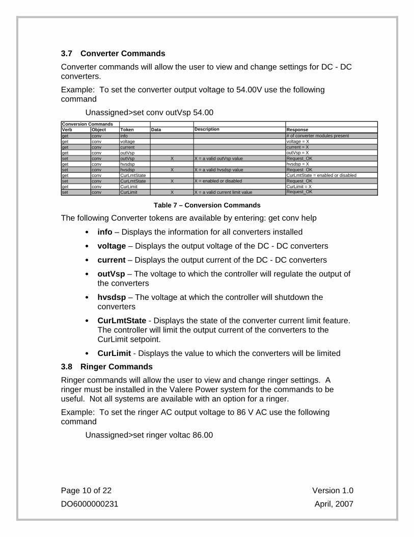
Unassigned>set conv outVsp 54.00 Conversion CommandsVerb Object Token Data Description Responseget conv info # of converter modules presentget conv voltage voltage = Xget conv current current = Xget conv outVsp outVsp = Xset conv outVsp X X = a valid outVsp value Request_OKget conv hvsdsp hvsdsp = Xset conv hvsdsp X X = a valid hvsdsp value Request_OKget conv CurLmtState CurLmtState = enabled or disabledset conv CurLmtState X X = enabled or disabled Request_OKget conv CurLimit CurLimit = Xset conv CurLimit X X = a valid current limit value Request_OK
Table 7 – Conversion Commands
The following Converter tokens are available by entering: get conv help
•••• info – Displays the information for all converters installed
•••• voltage – Displays the output voltage of the DC - DC converters
•••• current – Displays the output current of the DC - DC converters
•••• outVsp – The voltage to which the controller will regulate the output of the converters
•••• hvsdsp – The voltage at which the controller will shutdown the converters
•••• CurLmtState - Displays the state of the converter current limit feature. The controller will limit the output current of the converters to the CurLimit setpoint.
•••• CurLimit - Displays the value to which the converters will be limited
3.8 Ringer Commands
Ringer commands will allow the user to view and change ringer settings. A ringer must be installed in the Valere Power system for the commands to be useful. Not all systems are available with an option for a ringer.
Example: To set the ringer AC output voltage to 86 V AC use the following command
Unassigned>set ringer voltac 86.00
Page 11 of 22 Version 1.0
DO6000000231 April, 2007
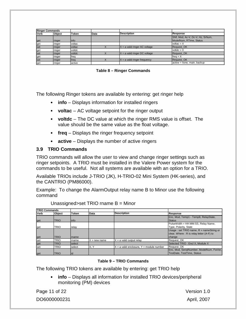
Ringer CommandsVerb Object Token Data Description Response
get ringer infoShlf, Mod, Ac-V, Dc-V, Hz, SrNum, ModelNum, RTime, Status
get ringer voltac voltac = Xset ringer voltac X X = a valid ringer AC voltage Request_OKget ringer voltdc voltdc = Xset ringer voltdc X X = a valid ringer DC voltage Request_OKget ringer freq freq = Xset ringer freq X X = a valid ringer frequency Request_OKget ringer active active = none, main, backup
Table 8 – Ringer Commands
The following Ringer tokens are available by entering: get ringer help
•••• info – Displays information for installed ringers
•••• voltac – AC voltage setpoint for the ringer output
•••• voltdc – The DC value at which the ringer RMS value is offset. The value should be the same value as the float voltage.
•••• freq – Displays the ringer frequency setpoint
•••• active – Displays the number of active ringers
3.9 TRIO Commands
TRIO commands will allow the user to view and change ringer settings such as ringer setpoints. A TRIO must be installed in the Valere Power system for the commands to be useful. Not all systems are available with an option for a TRIO.
Available TRIOs include J-TRIO (JK), H-TRIO-02 Mini System (HK-series), and the CANTRIO (PM86000).
Example: To change the AlarmOutput relay name B to Minor use the following command
Unassigned>set TRIO rname B = Minor TRIO CommandsVerb Object Token Data Description Response
get TRIO infoEnc, Mod, Temp1 - Temp8, RelayState, Status
get TRIO relayPulseWidth = HH:MM:SS, Relay Name, Type, Polarity, State
get TRIO rname
Usage : set TRIO name, R = nameString or clear, Where : R is relay letter (A-F) to change
set TRIO rname X = new name X = a valid output relay Request_OKget TRIO select Selected TRIO : Encl X, Module Xset TRIO select X, Y X = a valid enclosure, Y = module number Request_OK
get TRIO idEnc, Mod, SerialNumber, ModelNum, FwVer, TestDate, TestTime, Status
Table 9 – TRIO Commands
The following TRIO tokens are available by entering: get TRIO help
•••• info – Displays all information for installed TRIO devices/peripheral monitoring (PM) devices
Page 12 of 22 Version 1.0
DO6000000231 April, 2007
•••• relay – Displays the state of the output relays for all TRIOs installed
•••• rname – Displays the name assigned to the output alarm relays on a TRIO device
•••• select – Displays selected TRIO enclosure and module. A TRIO must be selected to display specific information concerning that TRIO.
•••• id – Displays the enclosure, module, serial number, model number, and status of the TRIOs
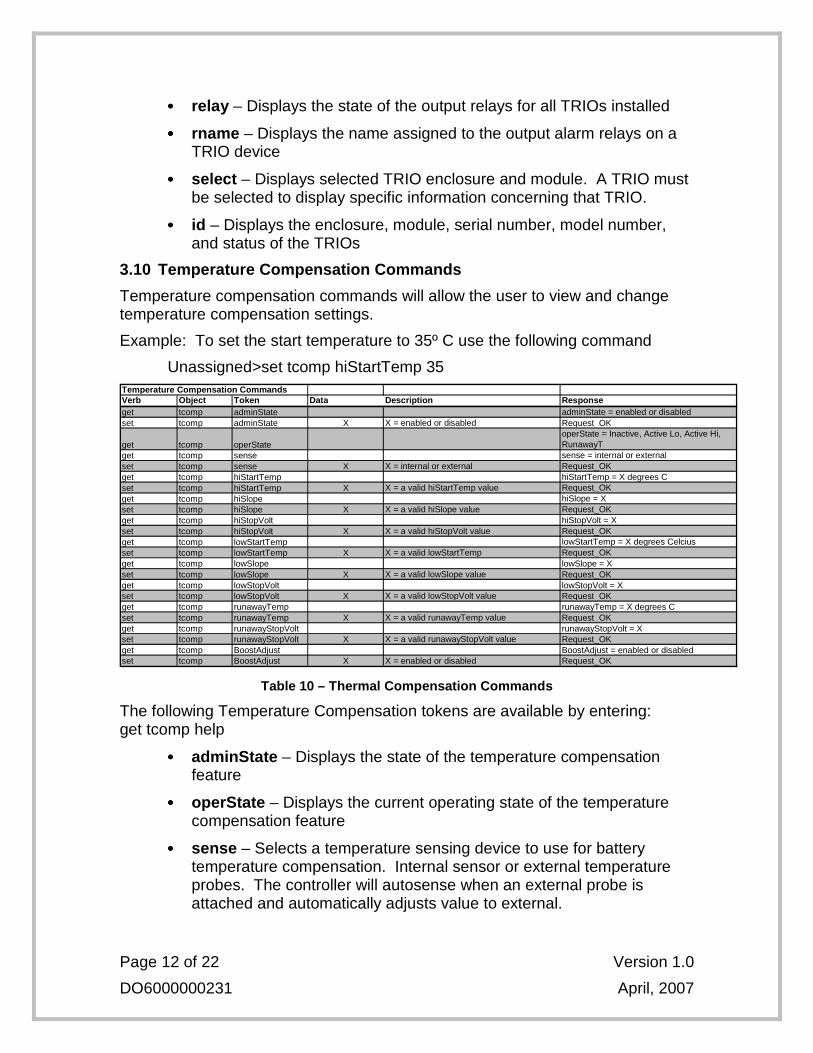
3.10 Temperature Compensation Commands
Temperature compensation commands will allow the user to view and change temperature compensation settings.
Example: To set the start temperature to 35º C use the following command
Unassigned>set tcomp hiStartTemp 35 Temperature Compensation CommandsVerb Object Token Data Description Responseget tcomp adminState adminState = enabled or disabledset tcomp adminState X X = enabled or disabled Request_OK
get tcomp operStateoperState = Inactive, Active Lo, Active Hi, RunawayT
get tcomp sense sense = internal or externalset tcomp sense X X = internal or external Request_OKget tcomp hiStartTemp hiStartTemp = X degrees Cset tcomp hiStartTemp X X = a valid hiStartTemp value Request_OKget tcomp hiSlope hiSlope = Xset tcomp hiSlope X X = a valid hiSlope value Request_OKget tcomp hiStopVolt hiStopVolt = Xset tcomp hiStopVolt X X = a valid hiStopVolt value Request_OKget tcomp lowStartTemp lowStartTemp = X degrees Celciusset tcomp lowStartTemp X X = a valid lowStartTemp Request_OKget tcomp lowSlope lowSlope = Xset tcomp lowSlope X X = a valid lowSlope value Request_OKget tcomp lowStopVolt lowStopVolt = Xset tcomp lowStopVolt X X = a valid lowStopVolt value Request_OKget tcomp runawayTemp runawayTemp = X degrees Cset tcomp runawayTemp X X = a valid runawayTemp value Request_OKget tcomp runawayStopVolt runawayStopVolt = Xset tcomp runawayStopVolt X X = a valid runawayStopVolt value Request_OKget tcomp BoostAdjust BoostAdjust = enabled or disabledset tcomp BoostAdjust X X = enabled or disabled Request_OK
Table 10 – Thermal Compensation Commands
The following Temperature Compensation tokens are available by entering: get tcomp help
•••• adminState – Displays the state of the temperature compensation feature
•••• operState – Displays the current operating state of the temperature compensation feature
•••• sense – Selects a temperature sensing device to use for battery temperature compensation. Internal sensor or external temperature probes. The controller will autosense when an external probe is attached and automatically adjusts value to external.
Page 13 of 22 Version 1.0
DO6000000231 April, 2007
•••• hiStartTemp – The temperature at which the controller activates the high temperature compensation feature
•••• hiSlope – The slope value at which the controller will reduce the float voltage per degree if high temperature compensation is active
•••• hiStopVolt – The minimum voltage to which the controller will reduce the plant voltage for high temperature compensation
•••• lowStartTemp – The temperature at which the controller activates the low temperature compensation feature
•••• lowSlope – The slope value at which the controller will increase the float voltage per degree if low temperature compensation is active
•••• lowStopVolt – The maximum voltage to which the controller will increase the plant voltage for low temperature compensation
•••• runawayTemp – The temperature at which the controller will activate the thermal runaway feature
•••• runawayStopVolt – The voltage to which the rectifiers will reduce for temperatures above the runaway temperature
•••• BoostAdjust – Displays the thermal compensation BoostAdjust status
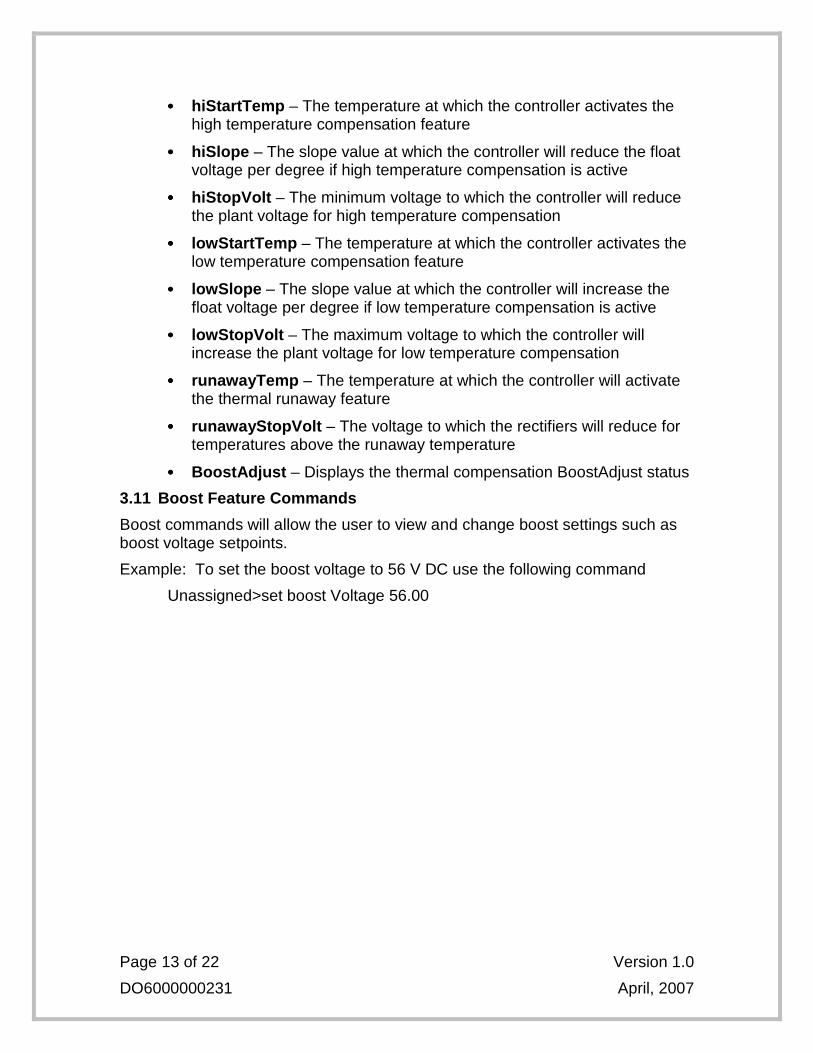
3.11 Boost Feature Commands
Boost commands will allow the user to view and change boost settings such as boost voltage setpoints.
Example: To set the boost voltage to 56 V DC use the following command
Unassigned>set boost Voltage 56.00
Page 14 of 22 Version 1.0
DO6000000231 April, 2007
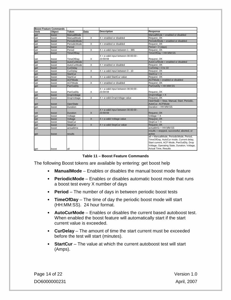
Boost Feature CommandsVerb Object Token Data Description Responseget boost ManualMode ManualMode = enabled or disabledset boost ManualMode X X = enabled or disabled Request_OKget boost PeriodicMode PeriodicMode = enabled or disabledset boost PeriodicMode X X = enabled or disabled Request_OKget boost Period Period = # (days)set boost Period X X = a valid input between 1 - 365 Request_OKget boost TimeOfDay TimeOfDay = HH:MM:SS
set boost TimeOfDay XX = a valid input between 00:00:00 - 23:59:59 Request_OK
get boost AutoCurMode AutoCurMode = enabled or disabledset boost AutoCurMode X X = enabled or disabled Request_OKget boost CurDelay CurDelay = 0 to 10set boost CurDelay X X = a valid input between 0 - 10 Request_OKget boost StartCur StartCur = Xset boost StartCur X X = a valid StartCur value Request_OKget boost ACFMode ACFMode = enabled or disabledset boost ACFMode X X = enabled or disabled Request_OKget boost PwrOutDly PwrOutDly = HH:MM:SS
set boost PwrOutDly XX = a valid input between 00:00:00 - 23:59:59 Request_OK
get boost DropVoltage DropVoltage = Xset boost DropVoltage X X = a valid DropVoltage value Request_OK
get boost OperStateOperState = Stop, Manual, Start, Periodic, AutoCur, ACFMode
get boost Duration Duration = HH:MM:SS
set boost Duration XX = a valid input between 00:00:00 - 23:59:59 Request_OK
get boost Voltage Voltage = Xset boost Voltage X X = a valid Voltage value Request_OKget boost StopCur StopCur = Xset boost StopCur X X = a valid StopCur value Request_OKget boost actualtime actualtime = HH:MM:SS
get boost resultsresults = stopped, successful, aborted, or active
get boost all
all = ManualMode, PeriodicMode, Period, TimeOfDay, AutoCur mode, Current delay, Start current, ACF Mode, PwrOutDly, Drop Voltage, Operating State, Duration, Voltage, Actual Time, Results
Table 11 – Boost Feature Commands
The following Boost tokens are available by entering: get boost help
•••• ManualMode – Enables or disables the manual boost mode feature
•••• PeriodicMode – Enables or disables automatic boost mode that runs a boost test every X number of days
•••• Period – The number of days in between periodic boost tests
•••• TimeOfDay – The time of day the periodic boost mode will start (HH:MM:SS). 24 hour format.
•••• AutoCurMode – Enables or disables the current based autoboost test. When enabled the boost feature will automatically start if the start current value is exceeded.
•••• CurDelay – The amount of time the start current must be exceeded before the test will start (minutes).
•••• StartCur – The value at which the current autoboost test will start (Amps).
Page 15 of 22 Version 1.0
DO6000000231 April, 2007
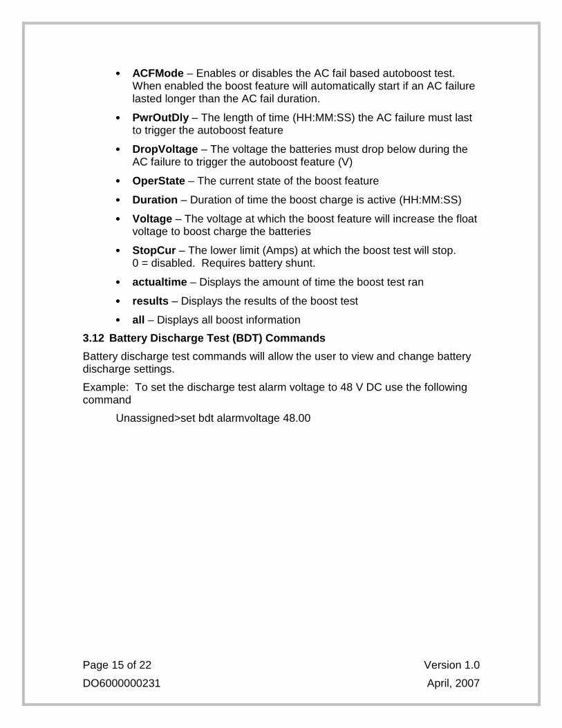
•••• ACFMode – Enables or disables the AC fail based autoboost test. When enabled the boost feature will automatically start if an AC failure lasted longer than the AC fail duration.
•••• PwrOutDly – The length of time (HH:MM:SS) the AC failure must last to trigger the autoboost feature
•••• DropVoltage – The voltage the batteries must drop below during the AC failure to trigger the autoboost feature (V)
•••• OperState – The current state of the boost feature
•••• Duration – Duration of time the boost charge is active (HH:MM:SS)
•••• Voltage – The voltage at which the boost feature will increase the float voltage to boost charge the batteries
•••• StopCur – The lower limit (Amps) at which the boost test will stop. 0 = disabled. Requires battery shunt.
•••• actualtime – Displays the amount of time the boost test ran
•••• results – Displays the results of the boost test
•••• all – Displays all boost information
3.12 Battery Discharge Test (BDT) Commands
Battery discharge test commands will allow the user to view and change battery discharge settings.
Example: To set the discharge test alarm voltage to 48 V DC use the following command
Unassigned>set bdt alarmvoltage 48.00
Page 16 of 22 Version 1.0
DO6000000231 April, 2007
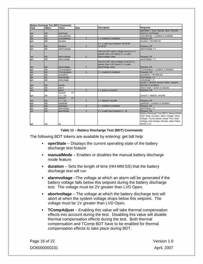
Battery Discharge Test (BDT) CommandsVerb Object Token Data Description Response
get bdt operStateoperState = Stop, Manual, Start, Periodic, AutoCur, ACFMode
get bdt manualMode manualMode = enabled or disabledset bdt manualMode X X = enabled or disabled Request_OKget bdt duration duration = HH:MM:SS
set bdt duration XX = a valid input between 00:00:00 - 23:59:59 Request_OK
get bdt alarmvoltage alarmvoltage = X
set bdt alarmvoltage X
Sets the BDT alarm voltage (must be 2 V greater than LVD Open) X = a valid alarmvoltage value Request_OK
get bdt abortvoltage abortvoltage = X
set bdt abortvoltage X
Sets the BDT abort voltage (must be 1V greater than LVD Open) X = a valid abortvoltage value Request_OK
get bdt TCompAdjust TCompAdjust = enabled or disabledset bdt TCompAdjust X X = enabled or disabled Request_OKget bdt actualtime actualtime = HH:MM:SSget bdt startvoltage startvoltage = Xget bdt endvoltage endvoltage = X
get bdt resultsresults = cleared, passed, failed, stopped, aborted, in progress
get bdt alarm Alarm State = active or inactiveset bdt alarm X X = active or inactive Request_OK
get bdtSchedY (Y = 1 - 12) SchedY = MM/DD, HH:MM
set bdtSchedY (Y = 1 - 12) X X = MM/DD, HH:MM Request_OK
get bdt oppMode oppMode = enabled or disabledset bdt oppMode X X = enabled or disabled Request_OKget bdt alarmDelay alarmDelay = Xset bdt alarmDelay X X = a valid input between 0 - 30 Request_OK
get bdt all
Battery Discharge Test (BDT): Manual Mode, Oper State, Duration, Alarm Voltage, Abort Voltage, Tcomp Adjust, Actual Time, Start Voltage, End Voltage, Results, Alarm State, Sched 1-12
Table 12 – Battery Discharge Test (BDT) Commands
The following BDT tokens are available by entering: get bdt help
•••• operState – Displays the current operating state of the battery discharge test feature
•••• manualMode – Enables or disables the manual battery discharge mode feature
•••• duration – Sets the length of time (HH:MM:SS) that the battery discharge test will run
•••• alarmvoltage –The voltage at which an alarm will be generated if the battery voltage falls below this setpoint during the battery discharge test. The voltage must be 2V greater than LVD Open.
•••• abortvoltage – The voltage at which the battery discharge test will abort at when the system voltage drops below this setpoint. The voltage must be 1V greater than LVD Open.
•••• TCompAdjust – Enabling this value will take thermal compensation effects into account during the test. Disabling this value will disable thermal compensation effects during the test. Both thermal compensation and TComp BDT have to be enabled for thermal compensation effects to take place during BDT.
Page 17 of 22 Version 1.0
DO6000000231 April, 2007
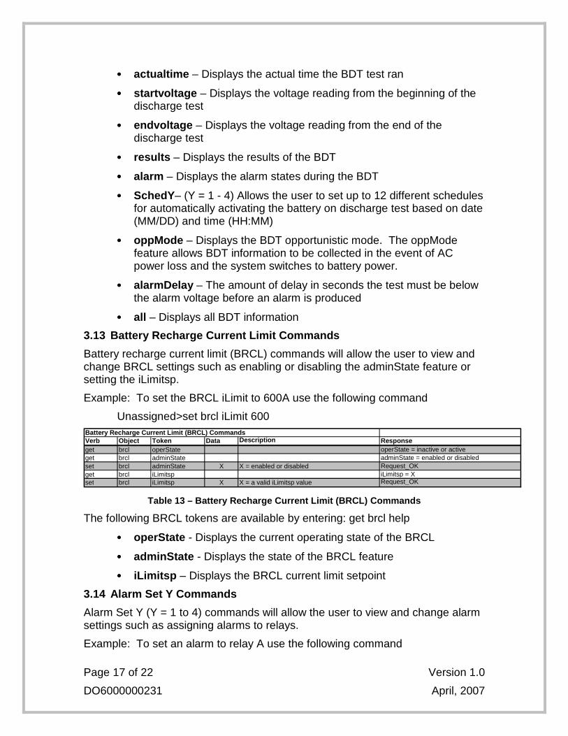
•••• actualtime – Displays the actual time the BDT test ran
•••• startvoltage – Displays the voltage reading from the beginning of the discharge test
•••• endvoltage – Displays the voltage reading from the end of the discharge test
•••• results – Displays the results of the BDT
•••• alarm – Displays the alarm states during the BDT
•••• SchedY – (Y = 1 - 4) Allows the user to set up to 12 different schedules for automatically activating the battery on discharge test based on date (MM/DD) and time (HH:MM)
•••• oppMode – Displays the BDT opportunistic mode. The oppMode feature allows BDT information to be collected in the event of AC power loss and the system switches to battery power.
•••• alarmDelay – The amount of delay in seconds the test must be below the alarm voltage before an alarm is produced
•••• all – Displays all BDT information
3.13 Battery Recharge Current Limit Commands
Battery recharge current limit (BRCL) commands will allow the user to view and change BRCL settings such as enabling or disabling the adminState feature or setting the iLimitsp.
Example: To set the BRCL iLimit to 600A use the following command
Unassigned>set brcl iLimit 600 Battery Recharge Current Limit (BRCL) CommandsVerb Object Token Data Description Responseget brcl operState operState = inactive or activeget brcl adminState adminState = enabled or disabledset brcl adminState X X = enabled or disabled Request_OKget brcl iLimitsp iLimitsp = Xset brcl iLimitsp X X = a valid iLimitsp value Request_OK
Table 13 – Battery Recharge Current Limit (BRCL) Co mmands
The following BRCL tokens are available by entering: get brcl help
•••• operState - Displays the current operating state of the BRCL
•••• adminState - Displays the state of the BRCL feature
•••• iLimitsp – Displays the BRCL current limit setpoint
3.14 Alarm Set Y Commands
Alarm Set Y (Y = 1 to 4) commands will allow the user to view and change alarm settings such as assigning alarms to relays.
Example: To set an alarm to relay A use the following command
Page 18 of 22 Version 1.0
DO6000000231 April, 2007
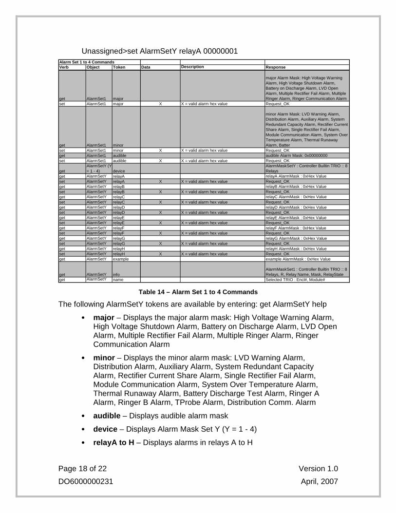
Unassigned>set AlarmSetY relayA 00000001 Alarm Set 1 to 4 CommandsVerb Object Token Data Description Response
get AlarmSet1 major
major Alarm Mask: High Voltage Warning Alarm, High Voltage Shutdown Alarm, Battery on Discharge Alarm, LVD Open Alarm, Multiple Rectifier Fail Alarm, Multiple Ringer Alarm, Ringer Communication Alarm
set AlarmSet1 major X X = valid alarm hex value Request_OK
get AlarmSet1 minor
minor Alarm Mask: LVD Warning Alarm, Distribution Alarm, Auxiliary Alarm, System Redundant Capacity Alarm, Rectifier Current Share Alarm, Single Rectifier Fail Alarm, Module Communication Alarm, System Over Temperature Alarm, Thermal Runaway Alarm, Batter
set AlarmSet1 minor X X = valid alarm hex value Request_OKget AlarmSet1 audible audible Alarm Mask: 0x00000000set AlarmSet1 audible X X = valid alarm hex value Request_OK
getAlarmSetY (Y = 1 - 4) device
AlarmMaskSetY : Controller Builtin TRIO :: 8 Relays
get AlarmSetY relayA relayA AlarmMask : 0xHex Valueset AlarmSetY relayA X X = valid alarm hex value Request_OKget AlarmSetY relayB relayB AlarmMask : 0xHex Valueset AlarmSetY relayB X X = valid alarm hex value Request_OKget AlarmSetY relayC relayC AlarmMask : 0xHex Valueset AlarmSetY relayC X X = valid alarm hex value Request_OKget AlarmSetY relayD relayD AlarmMask : 0xHex Valueset AlarmSetY relayD X X = valid alarm hex value Request_OKget AlarmSetY relayE relayE AlarmMask : 0xHex Valueset AlarmSetY relayE X X = valid alarm hex value Request_OKget AlarmSetY relayF relayF AlarmMask : 0xHex Valueset AlarmSetY relayF X X = valid alarm hex value Request_OKget AlarmSetY relayG relayG AlarmMask : 0xHex Valueset AlarmSetY relayG X X = valid alarm hex value Request_OKget AlarmSetY relayH relayH AlarmMask : 0xHex Valueset AlarmSetY relayH X X = valid alarm hex value Request_OKget AlarmSetY example example AlarmMask : 0xHex Value
get AlarmSetY infoAlarmMaskSet1 : Controller Builtin TRIO :: 8 Relays, R, Relay Name, Mask, RelayState
get AlarmSetY name Selected TRIO : Encl#, Module#
Table 14 – Alarm Set 1 to 4 Commands
The following AlarmSetY tokens are available by entering: get AlarmSetY help
•••• major – Displays the major alarm mask: High Voltage Warning Alarm, High Voltage Shutdown Alarm, Battery on Discharge Alarm, LVD Open Alarm, Multiple Rectifier Fail Alarm, Multiple Ringer Alarm, Ringer Communication Alarm
•••• minor – Displays the minor alarm mask: LVD Warning Alarm, Distribution Alarm, Auxiliary Alarm, System Redundant Capacity Alarm, Rectifier Current Share Alarm, Single Rectifier Fail Alarm, Module Communication Alarm, System Over Temperature Alarm, Thermal Runaway Alarm, Battery Discharge Test Alarm, Ringer A Alarm, Ringer B Alarm, TProbe Alarm, Distribution Comm. Alarm
•••• audible – Displays audible alarm mask
•••• device – Displays Alarm Mask Set Y (Y = 1 - 4)
•••• relayA to H – Displays alarms in relays A to H
Page 19 of 22 Version 1.0
DO6000000231 April, 2007
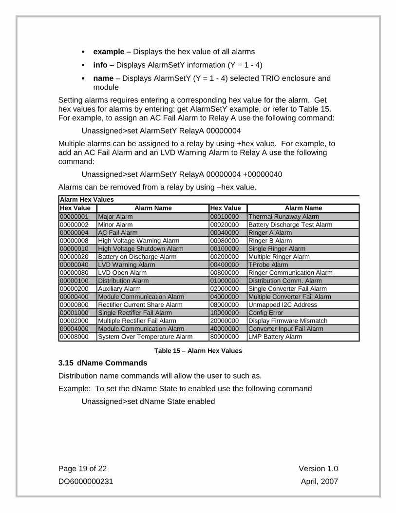
•••• example – Displays the hex value of all alarms
•••• info – Displays AlarmSetY information (Y = 1 - 4)
•••• name – Displays AlarmSetY (Y = 1 - 4) selected TRIO enclosure and module
Setting alarms requires entering a corresponding hex value for the alarm. Get hex values for alarms by entering: get AlarmSetY example, or refer to Table 15. For example, to assign an AC Fail Alarm to Relay A use the following command:
Unassigned>set AlarmSetY RelayA 00000004
Multiple alarms can be assigned to a relay by using +hex value. For example, to add an AC Fail Alarm and an LVD Warning Alarm to Relay A use the following command:
Unassigned>set AlarmSetY RelayA 00000004 +00000040
Alarms can be removed from a relay by using –hex value.
Hex Value Hex Value00000001 0001000000000002 0002000000000004 0004000000000008 0008000000000010 0010000000000020 0020000000000040 0040000000000080 0080000000000100 0100000000000200 0200000000000400 0400000000000800 0800000000001000 1000000000002000 2000000000004000 4000000000008000 80000000
Battery on Discharge Alarm
Minor AlarmAC Fail AlarmHigh Voltage Warning AlarmHigh Voltage Shutdown Alarm
Alarm Hex ValuesAlarm Name Alarm Name
Major Alarm
LVD Warning AlarmLVD Open AlarmDistribution AlarmAuxiliary AlarmModule Communication AlarmRectifier Current Share AlarmSingle Rectifier Fail AlarmMultiple Rectifier Fail AlarmModule Communication AlarmSystem Over Temperature Alarm
Thermal Runaway AlarmBattery Discharge Test AlarmRinger A AlarmRinger B AlarmSingle Ringer AlarmMultiple Ringer AlarmTProbe AlarmRinger Communication AlarmDistribution Comm. AlarmSingle Converter Fail AlarmMultiple Converter Fail AlarmUnmapped I2C AddressConfig ErrorDisplay Firmware MismatchConverter Input Fail AlarmLMP Battery Alarm
Table 15 – Alarm Hex Values
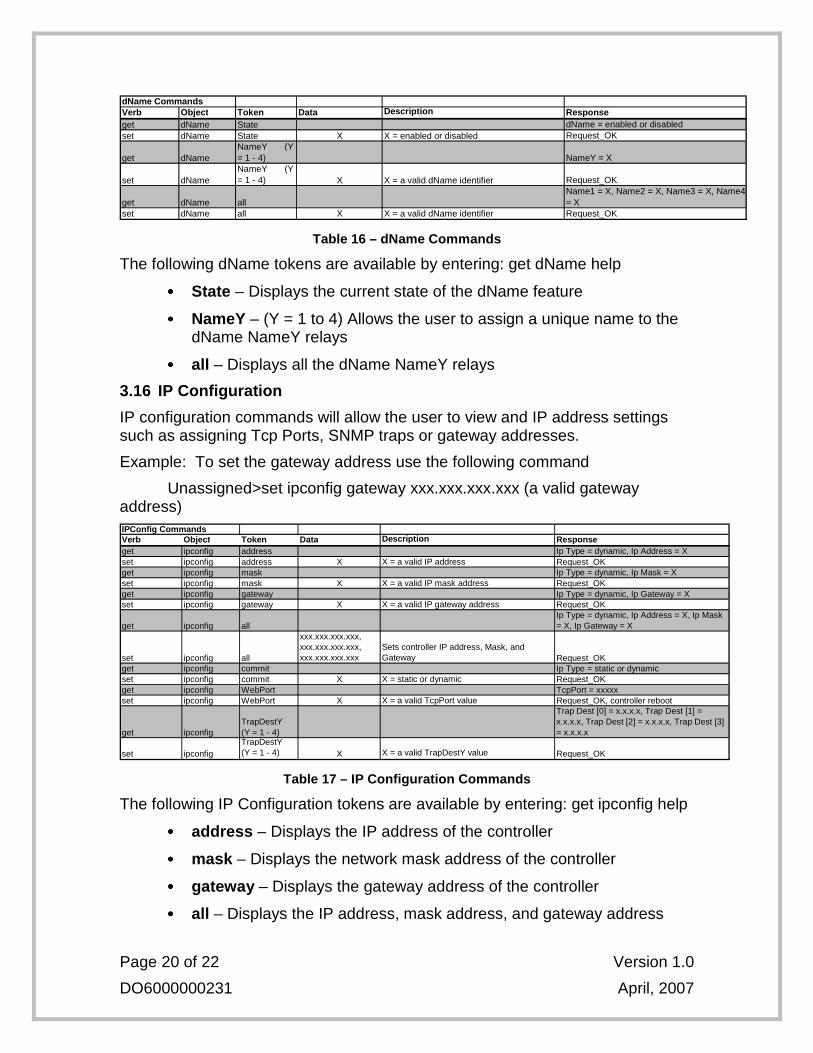
3.15 dName Commands
Distribution name commands will allow the user to such as.
Example: To set the dName State to enabled use the following command
Unassigned>set dName State enabled
Page 20 of 22 Version 1.0
DO6000000231 April, 2007
dName CommandsVerb Object Token Data Description Responseget dName State dName = enabled or disabledset dName State X X = enabled or disabled Request_OK
get dNameNameY (Y = 1 - 4) NameY = X
set dNameNameY (Y = 1 - 4) X X = a valid dName identifier Request_OK
get dName allName1 = X, Name2 = X, Name3 = X, Name4 = X
set dName all X X = a valid dName identifier Request_OK
Table 16 – dName Commands
The following dName tokens are available by entering: get dName help
•••• State – Displays the current state of the dName feature
•••• NameY – (Y = 1 to 4) Allows the user to assign a unique name to the dName NameY relays
•••• all – Displays all the dName NameY relays
3.16 IP Configuration
IP configuration commands will allow the user to view and IP address settings such as assigning Tcp Ports, SNMP traps or gateway addresses.
Example: To set the gateway address use the following command
Unassigned>set ipconfig gateway xxx.xxx.xxx.xxx (a valid gateway address) IPConfig CommandsVerb Object Token Data Description Responseget ipconfig address Ip Type = dynamic, Ip Address = Xset ipconfig address X X = a valid IP address Request_OKget ipconfig mask Ip Type = dynamic, Ip Mask = Xset ipconfig mask X X = a valid IP mask address Request_OKget ipconfig gateway Ip Type = dynamic, Ip Gateway = Xset ipconfig gateway X X = a valid IP gateway address Request_OK
get ipconfig allIp Type = dynamic, Ip Address = X, Ip Mask = X, Ip Gateway = X
set ipconfig all
xxx.xxx.xxx.xxx, xxx.xxx.xxx.xxx, xxx.xxx.xxx.xxx
Sets controller IP address, Mask, and Gateway Request_OK
get ipconfig commit Ip Type = static or dynamicset ipconfig commit X X = static or dynamic Request_OKget ipconfig WebPort TcpPort = xxxxxset ipconfig WebPort X X = a valid TcpPort value Request_OK, controller reboot
get ipconfigTrapDestY (Y = 1 - 4)
Trap Dest [0] = x.x.x.x, Trap Dest [1] = x.x.x.x, Trap Dest [2] = x.x.x.x, Trap Dest [3] = x.x.x.x
set ipconfigTrapDestY (Y = 1 - 4) X X = a valid TrapDestY value Request_OK
Table 17 – IP Configuration Commands
The following IP Configuration tokens are available by entering: get ipconfig help
•••• address – Displays the IP address of the controller
•••• mask – Displays the network mask address of the controller
•••• gateway – Displays the gateway address of the controller
•••• all – Displays the IP address, mask address, and gateway address
Page 21 of 22 Version 1.0
DO6000000231 April, 2007
•••• commit – Displays the state, either static or dynamic, of the IP address
•••• WebPort – Displays the Tcp port number being used for webpage access.
•••• TrapDestY – (Y = 1 to 4) Displays the IP address where the SNMP traps will be sent. Up to 4 addresses can be added.
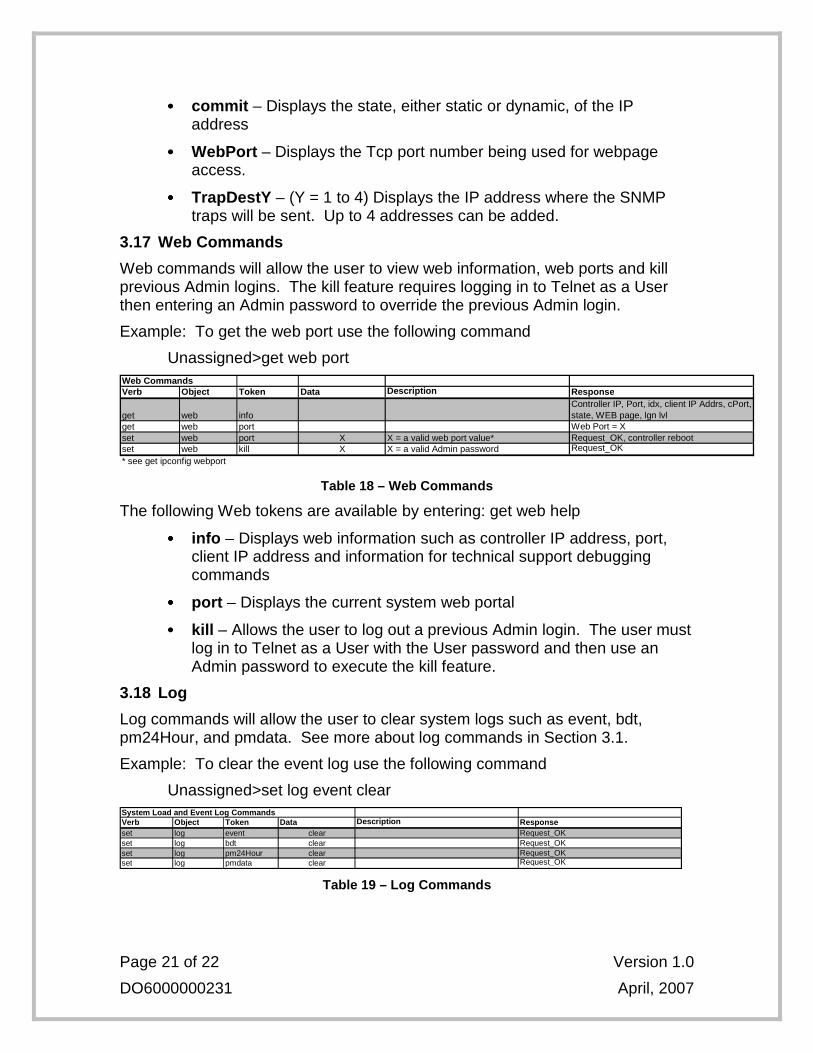
3.17 Web Commands
Web commands will allow the user to view web information, web ports and kill previous Admin logins. The kill feature requires logging in to Telnet as a User then entering an Admin password to override the previous Admin login.
Example: To get the web port use the following command
Unassigned>get web port Web CommandsVerb Object Token Data Description Response
get web infoController IP, Port, idx, client IP Addrs, cPort, state, WEB page, lgn lvl
get web port Web Port = Xset web port X X = a valid web port value* Request_OK, controller rebootset web kill X X = a valid Admin password Request_OK
* see get ipconfig webport
Table 18 – Web Commands
The following Web tokens are available by entering: get web help
•••• info – Displays web information such as controller IP address, port, client IP address and information for technical support debugging commands
•••• port – Displays the current system web portal
•••• kill – Allows the user to log out a previous Admin login. The user must log in to Telnet as a User with the User password and then use an Admin password to execute the kill feature.
3.18 Log
Log commands will allow the user to clear system logs such as event, bdt, pm24Hour, and pmdata. See more about log commands in Section 3.1.
Example: To clear the event log use the following command
Unassigned>set log event clear
Verb Object Token Data Description Responseset log event clear Request_OKset log bdt clear Request_OKset log pm24Hour clear Request_OKset log pmdata clear Request_OK
System Load and Event Log Commands
Table 19 – Log Commands

Page 22 of 22 Version 1.0
DO6000000231 April, 2007
The following Log tokens are available by entering: get log help
•••• event – Clears the event log
•••• bdt – Clears the Battery Discharge Test (BDT) log
•••• pm24Hour – Clears the pm24Hour log
•••• pmdata – Clears the pmdata log