Embed Size (px)
Citation preview

SCALAMAX Protocol LX-10 Series GatewaysDocument: IN-0000033-R01
by
For additional information, please contact uswww.teslights.com - [email protected]
Teslights Hybrid Lighting
SCALAMAX ProtocolLX-12D Gateway
Document Number: IN-0000033-R01Copyright Teslights, LLC2010-2020
Compliant
by
Page 2
SCALAMAX Protocol LX-10 Series GatewaysDocument: IN-0000033-R01
by
For additional information, please contact uswww.teslights.com - [email protected]
Index
Warning
This guide is for persons who have received training and are qualified to work with electricity and electrical metering equipment. All applicable national and local electrical codes and standards must be followed. Failure to follow proper procedures may result inserious bodily harm including death.
Disclaimer
The product described herein may be changed or enhanced from time to time. This information does not constitute commitments or representations by Teslights LLC, and is subject to change without notice.
Images shown are a representation only. They may not match exactly with the real equipment.
Warning ............................................................................................................................................................................................................... 2
Disclaimer ........................................................................................................................................................................................................... 2
1. Overview ........................................................................................................................................................................................................ 3
1.1. LX-12D Gateway concept .................................................................................................................................................. 3
1.2. LX-12 Gateway features ..................................................................................................................................................... 5
1.3 Block Diagram ......................................................................................................................................................................... 6
1.4 Connectors ............................................................................................................................................................................... 7
2. Technical Specifications ........................................................................................................................................................................... 8
3. Environmental data .................................................................................................................................................................................... 8
4. Dimensions .................................................................................................................................................................................................... 9
5. Approvals ....................................................................................................................................................................................................... 9
6. Installation guide ......................................................................................................................................................................................... 10
6.1. Single-phase / three-phase power input ..................................................................................................................... 10
6.2. Current transformers connection ................................................................................................................................. 10
6.3. RS-485 Connection ............................................................................................................................................................. 11
6.4 4G/LTE and GPS Antenna installation .......................................................................................................................... 12
6.5 Installation example LX-1x Gateway with an MR-4850 actuator ..................................................................... 12
7. Cautions and warnings.............................................................................................................................................................................. 13
8. Product Limited Warranty ...................................................................................................................................................................... 13
9. Release Dates ............................................................................................................................................................................................... 13

Page 3
SCALAMAX Protocol LX-10 Series GatewaysDocument: IN-0000033-R01
by
For additional information, please contact uswww.teslights.com - [email protected]
1. Overview
SCALAMAX family of “Industrial Internet of Things” Gateways are resourceful multifunction controllers, equipped to interface with different and fully instrumented networks, perform required protocol conversions, and enable remote access to exploit the full potential of industrial internet. All models are LINUX based, and range from low cost single core processors, to powerful quad core processors suitable to handle the most demanding memory and computing requirements.
The devices include powerful error correction techniques which provide maximum robustness integrating DES, 3DES and AES encryption functionality to guarantee total data security.
The Gateways are devices well suited to manage energy efficiency for many kind of power system, as it integrates a complete Class 1 Power Meter, and is accessible through various interfaces, whether wired or wireless.
The build in memory capacity can store and save up to two years of historical meter data, as well as event and status information.
The Gateways communicate through different interfaces with external devices and can serve as a bridge to a cloud based CMS (Central Management System) such as SCLAMAX “Smart Firefly” ® software.
In outdoor lighting applications, the Gateways are usually installed inside the electrical cabinet which provides power to all luminaires within its segment. Depending on the implemented communication interfaces, it handles “point to point” or “segment” control by means of additional devices called MR-48xx.
The LX-12D model has an integrated high resolution TFT display with capacitive touch panel with an easy and intuitive MMI (Man Machine Interface).
Figure 1: LX-12 Gateway with integrated display
1.1. LX-12D Gateway concept
Figure 1: LX-12 Gateway with integrated display
ETH
RS-485AB
CtsI1I2I3
U1U2U3N
SIM
28 / 03 / 2017 18:56:33
LX - 12Power Meter and Cabinet Controller
GPS
4G / LTE

Page 4
SCALAMAX Protocol LX-10 Series GatewaysDocument: IN-0000033-R01
by
For additional information, please contact uswww.teslights.com - [email protected]
Screenshots:
Figure 2: Screen showing power consumption for the past 24h
Figure 2: Screen showing power consumption for the past 24h and a certain period in time

Page 5
SCALAMAX Protocol LX-10 Series GatewaysDocument: IN-0000033-R01
by
For additional information, please contact uswww.teslights.com - [email protected]
1.2. LX-12 Gateway features
The LX-12 Series is a universal Gateway with different functions and interface capabilities.
The series consists of three models with common features and some specific ones for each model.
Every LX-1x Gateway has within the standard device the following features:
• 1 x RS-485 communications port.• 1 x Ethernet 10/100 Mbps Full-Duplex port and auto MDI/MDIX with RJ45 interface for IP connectivity to devices such as
computers, cameras, audio systems …• 1 x Real Time Clock (RTC) for independent time management even if the main power fails by means of the integrated battery.• 1 x Battery for keeping the RTC and for a save shut down of the system when the main power is removed.
Model specific options are:
• Class 1 Power Meter, for full monitoring of the power consumption of the whole system, enabling alarms and event driven processes to be activated in case of certain power states
• 4G/LTE modem, for remote access using cellular networks.
These are the LX-1x Series models:
DevicesFeature
Power Meter 4G / LTE
LX-10
LX-11 X
LX- 12 X X
Page 6
SCALAMAX Protocol LX-10 Series GatewaysDocument: IN-0000033-R01
by
For additional information, please contact uswww.teslights.com - [email protected]
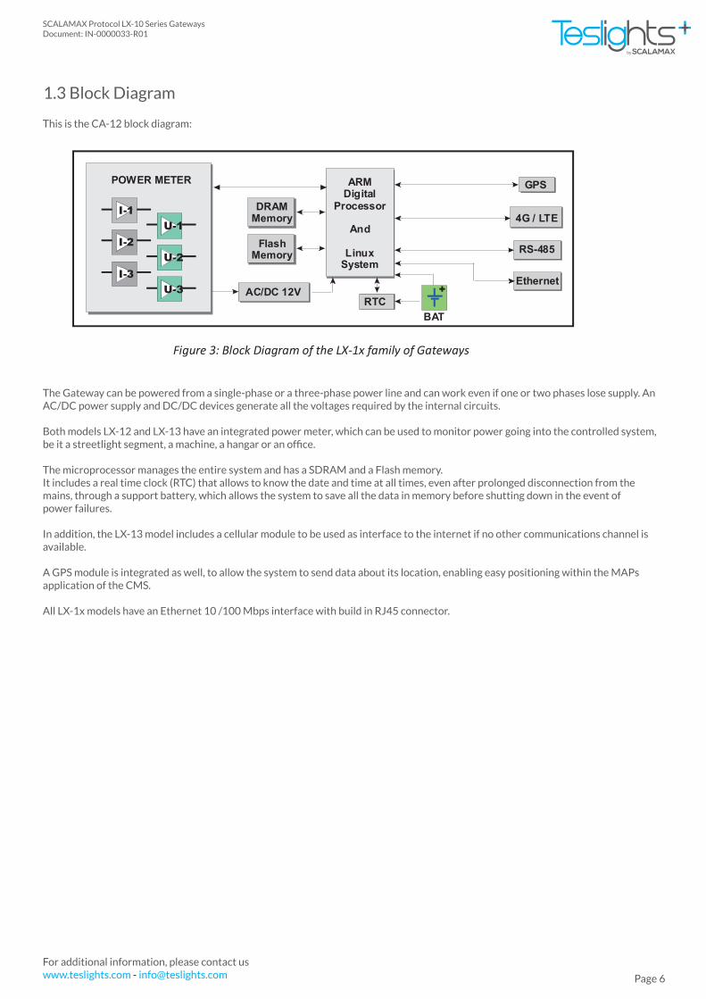
1.3 Block Diagram
This is the CA-12 block diagram:
The Gateway can be powered from a single-phase or a three-phase power line and can work even if one or two phases lose supply. An AC/DC power supply and DC/DC devices generate all the voltages required by the internal circuits.
Both models LX-12 and LX-13 have an integrated power meter, which can be used to monitor power going into the controlled system, be it a streetlight segment, a machine, a hangar or an office.
The microprocessor manages the entire system and has a SDRAM and a Flash memory.It includes a real time clock (RTC) that allows to know the date and time at all times, even after prolonged disconnection from the mains, through a support battery, which allows the system to save all the data in memory before shutting down in the event ofpower failures.
In addition, the LX-13 model includes a cellular module to be used as interface to the internet if no other communications channel is available.
A GPS module is integrated as well, to allow the system to send data about its location, enabling easy positioning within the MAPs application of the CMS.
All LX-1x models have an Ethernet 10 /100 Mbps interface with build in RJ45 connector.
I-2
I-3
I-1
U-2
U-3
U-1
POWER METER GPS
4G / LTE
RS-485
ARMDigital
Processor
And
LinuxSystem
AC/DC 12VRTC
BAT
+Ethernet
DRAMMemory
FlashMemory
Figure 3: Block Diagram of the LX-1x family of Gateways

Page 7
SCALAMAX Protocol LX-10 Series GatewaysDocument: IN-0000033-R01
by
For additional information, please contact uswww.teslights.com - [email protected]
1.4 Connectors
The equipment has the following connectors and terminal blocks:
Power line supply connector (5 pin terminal block) with the following inputs:
- Earth: Earth connection - Neutral: Neutral input - Phase 1: Phase 1 input - Phase 2: Phase 2 input - Phase 3: Phase 3 input
Current Transformers connector (6 pin terminal block) with the following inputs:
- CT Phase 3: Phase 3 current transformer input - CT Phase 2: Phase 2 current transformer input - CT Phase 1: Phase 1 current transformer input
RJ-45 connector. Ethernet port.
RS-485 connector (2 pin terminal block). Is an RS-485 interface to communicate with MODBUS devices such as the MR-4850 and MR-4859 actuators.
4G Antenna connector. SMA connector to plug a 4G antenna.
GPS Antenna connector. SMA connector to plug a GPS antenna.
SIM connector. Connector to insert a SIM card.

Page 8
SCALAMAX Protocol LX-10 Series GatewaysDocument: IN-0000033-R01
by
For additional information, please contact uswww.teslights.com - [email protected]
2. Technical Specifications
Input voltage range (1-phase) (VAC):Input frequency:Power factor:Maximum power consumption:
Throughput:MDI / MDIXFull Duplex
100 ~ 277 VAC50 ~ 60Hz> 0.8015 W
10 / 100 MbpsYesYes
Input
Ethernet
-25 ºC ~ 55ºC.-25 ºC ~ 85ºC.55 ºC
3. Environmental data
Usage for open type applications:
• IEC1 60529, IP-65.• Nema2, Type-1.
1. International Electrotechnical Commission, 3 Rue de Varembé, PO Box 131, CH-1211 Geneva 20, Switzerland2. National Electrical Manufacturers Association, 1300 North 17th Street, Rosslyn, VA 22209
Operating temperature range:Storage temperature range:Maximum temperature at the case:

Page 9
SCALAMAX Protocol LX-10 Series GatewaysDocument: IN-0000033-R01
by
For additional information, please contact uswww.teslights.com - [email protected]
These are the dimensions and the weight:
• Dimensions: 100 mm (Width) x 200 mm (Length*) x 30 mm (Height).• Weight: 900 g.
The Gateway has an IP20 aluminum enclosure which can be housed in an IP66 cabinetto provide additional protection.
Teslights LLC, certifies that the device meets the requirements of the following directives:
100
mm
200 mm
ETH
RS-485 AB
CtsI1I2I3
U1U2U3N
SIM
28 / 03 / 2017 18:56:33
LX - 12Power Meter and Cabinet Controller
GPS
4G / LTE
*NOTE: Length does not include the external connectors neither the 3G and GPS antennas
2006/95/CEEN60950-1: 2006+A11: 2009EN60529_ 1991+A1: 2000
2004/108/CE
EN55022:2006+A1:2007EN55024: 1998+A1:2001+A2:2003EN61000-3-2:2006EN61000-3-3: 2008EN61547: 1995+A1: 2000TGN17
4. Dimensiones y peso
5. Approvals

Page 10
SCALAMAX Protocol LX-10 Series GatewaysDocument: IN-0000033-R01
by
For additional information, please contact uswww.teslights.com - [email protected]
6. Installation guide
The Gateway is usually being installed in an electrical cabinet, and should only be accessible and manipulated by authorized technicians and persons.
Always remove power and unplug the power cord before working on the unit.
NOTE: The pictures in the following sections of the installation process may vary slightly from the supplied device. It could be a similar or an improved model.
6.1. Single-phase / three-phase power input
There’s a terminal block for the power voltage input (Earth, Neutral and Three-Phases).One wire for each power line will be used.
The European Union Low Voltage Regulation requires that all wires entering terminals to include wire ferrule terminals. They shall be well screwed at the terminal block, and make sure if you use stranded copper wires, no strand shall be loose to prevent short circuits.
Note: In the photo, the input voltage connector and the input current sensors one are shown.
Afterwards, connect the plugged into its mate.
6.2. Current transformers connection
For power metering, three current transformers are provided, which will be locked around the power wires at the entrance of the electrical cabinet, right after the main circuit breaker.
The outgoing wires of these transformers will be well screwed at the current sense (CTs) connector, as always, using wire ferrule terminals.
It is very important to locate the three sensors in the same metering direction, so current sense will be coherent. Otherwise, one sensor could be positive and other/s negative.
Page 11
SCALAMAX Protocol LX-10 Series GatewaysDocument: IN-0000033-R01
by
For additional information, please contact uswww.teslights.com - [email protected]
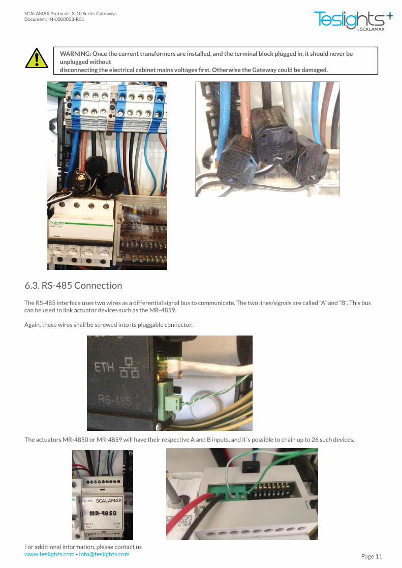
6.3. RS-485 Connection
The RS-485 interface uses two wires as a differential signal bus to communicate. The two lines/signals are called “A” and “B”. This bus can be used to link actuator devices such as the MR-4859.
Again, these wires shall be screwed into its pluggable connector.
WARNING: Once the current transformers are installed, and the terminal block plugged in, it should never be unplugged without disconnecting the electrical cabinet mains voltages first. Otherwise the Gateway could be damaged.
The actuators MR-4850 or MR-4859 will have their respective A and B inputs, and it´s possible to chain up to 26 such devices.

Page 12
SCALAMAX Protocol LX-10 Series GatewaysDocument: IN-0000033-R01
by
For additional information, please contact uswww.teslights.com - [email protected]
6.4 4G/LTE and GPS Antenna installation
6.5 Installation example LX-1x Gateway with an MR-4850 actuator
LX-1x family Gateways featuring 4G/LTE and GPS will be shipped with their respective antennas.
However, in some cases, the 4G coverage isn´t reliable, or metallic electrical cabinets are used, which attenuates RF signals. In such cases, the antenna can be replaced by higher gain models which can be attached outside the electrical cabinet.
The following picture illustrates how to connect an LX-1x GAteway to a MR-4850 in a three-phase electrical cabinet. The MR-4850 device controls the opening and closing of the output contactor to the streetlights.
The MR-4850 power supply is connected to the mains phase and neutral. Never connect it between two phases, as this voltage would destroy the device.
The coupling unit shown on the drawing is not used in the LX-1x family of Gateways.
CA13
Phas
e3
Phas
e2
Phas
e1
Neu
tral
Eart
h
CIRCUIT BREAKER
VOLT
AGE
INPU
TCU
RREN
TIN
PUT
RS-4
85PL
CSI
GNAL
3G
MR-4850
LINEIN
RELAYOUT
RS-485
P NN P
CONTACTOR
CONT
ROL
A B
AB
COUPLING UNIT
Page 13
SCALAMAX Protocol LX-10 Series GatewaysDocument: IN-0000033-R01
by
For additional information, please contact uswww.teslights.com - [email protected]
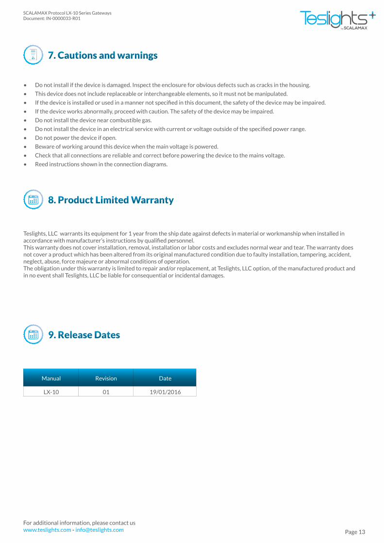
7. Cautions and warnings
8. Product Limited Warranty
9. Release Dates
Manual Revision Date
LX-10 01 19/01/2016
• Do not install if the device is damaged. Inspect the enclosure for obvious defects such as cracks in the housing.
• This device does not include replaceable or interchangeable elements, so it must not be manipulated.
• If the device is installed or used in a manner not specified in this document, the safety of the device may be impaired.
• If the device works abnormally, proceed with caution. The safety of the device may be impaired.
• Do not install the device near combustible gas.
• Do not install the device in an electrical service with current or voltage outside of the specified power range.
• Do not power the device if open.
• Beware of working around this device when the main voltage is powered.
• Check that all connections are reliable and correct before powering the device to the mains voltage.
• Reed instructions shown in the connection diagrams.
Teslights, LLC warrants its equipment for 1 year from the ship date against defects in material or workmanship when installed in accordance with manufacturer’s instructions by qualified personnel.This warranty does not cover installation, removal, installation or labor costs and excludes normal wear and tear. The warranty does not cover a product which has been altered from its original manufactured condition due to faulty installation, tampering, accident, neglect, abuse, force majeure or abnormal conditions of operation.The obligation under this warranty is limited to repair and/or replacement, at Teslights, LLC option, of the manufactured product and in no event shall Teslights, LLC be liable for consequential or incidental damages.