Embed Size (px)
Citation preview
8/20/2019 SCA-1 LPR Corrosion Rate Instrument Manual
http://slidepdf.com/reader/full/sca-1-lpr-corrosion-rate-instrument-manual 1/33
Model SCA-1 Corrater ®
Model SCA-1L Corrater ®
Corrosion MonitorUser Manual
ROHRBACK COSASCO SYSTEMS, INC.11841 E. Smith Avenue
Santa Fe Springs, CA 90670Tel: (562) 949-0123
(800) 635-6898Fax: (562) 949-3065
P/N 710514-Manual Rev.-B Serial Number:Revised: 11/3/04

8/20/2019 SCA-1 LPR Corrosion Rate Instrument Manual
http://slidepdf.com/reader/full/sca-1-lpr-corrosion-rate-instrument-manual 2/33
8/20/2019 SCA-1 LPR Corrosion Rate Instrument Manual
http://slidepdf.com/reader/full/sca-1-lpr-corrosion-rate-instrument-manual 3/33
CORROSOMETER®, CORRATER® are all registered trademarks of Rohrback Cosasco Systems Inc. Allrights reserved.
SCA-1/SCA-1L Corrater User Manual i

8/20/2019 SCA-1 LPR Corrosion Rate Instrument Manual
http://slidepdf.com/reader/full/sca-1-lpr-corrosion-rate-instrument-manual 4/33
SCA-1/SCA-1L Corrater User Manual ii
8/20/2019 SCA-1 LPR Corrosion Rate Instrument Manual
http://slidepdf.com/reader/full/sca-1-lpr-corrosion-rate-instrument-manual 5/33
Table of Contents
Chapter 1 Introduction ...................................................................................................................... 1
Chapter 2 Specifications .................................................................................................................. 3
Chapter 3 Installation ........................................................................................................................ 5
Chapter 4 Operation .......................................................................................................................... 9
Chapter 5 Maintenance................................................................................................................... 11
Chapter 6 Warranty ......................................................................................................................... 13
Chapter 7
SCA-1L Internal Data Logger Option ..........................................................................15
Appendix A Theory of Operation of CORRATER® Systems ......................................................19
Appendix B 2 Element Solution Resistivity Correction Curve ..................................................25
Appendix C Manufacturer’s Declaration of Conformity ............................................................. 27
SCA-1/SCA-1L Corrater User Manual iii

8/20/2019 SCA-1 LPR Corrosion Rate Instrument Manual
http://slidepdf.com/reader/full/sca-1-lpr-corrosion-rate-instrument-manual 6/33
SCA-1/SCA-1L Corrater User Manual iv
8/20/2019 SCA-1 LPR Corrosion Rate Instrument Manual
http://slidepdf.com/reader/full/sca-1-lpr-corrosion-rate-instrument-manual 7/33
Chapter 1
Introduction
1.0 GENERAL
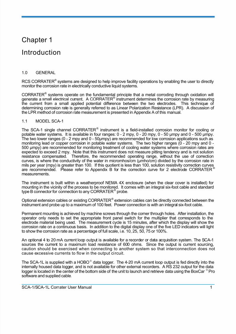
RCS CORRATER® systems are designed to help improve facility operations by enabling the user to directlymonitor the corrosion rate in electrically conductive liquid systems.
CORRATER® systems operate on the fundamental principle that a metal corroding through oxidation willgenerate a small electrical current. A CORRATER® instrument determines the corrosion rate by measuringthe current from a small applied potential difference between the two electrodes. This technique ofdetermining corrosion rate is generally referred to as Linear Polarization Resistance (LPR). A discussion ofthe LPR method of corrosion rate measurement is presented in Appendix A of this manual.
1.1 MODEL SCA-1
The SCA-1 single channel CORRATER® instrument is a field-installed corrosion monitor for cooling orpotable water systems. It is available in four ranges: 0 - 2 mpy, 0 - 20 mpy, 0 - 50 µmpy and 0 - 500 µmpy.The two lower ranges (0 - 2 mpy and 0 - 50µmpy) are recommended for low corrosion applications such asmonitoring lead or copper corrosion in potable water systems. The two higher ranges (0 - 20 mpy and 0 -500 µmpy) are recommended for monitoring treatment of cooling water systems where corrosion rates areexpected to exceed 2 mpy. Note that this instrument does not measure pitting tendency and is not solutionresistance compensated. Therefore, the recommended operating range, without the use of correctioncurves, is where the conductivity of the water in micromhos/cm (µmho/cm) divided by the corrosion rate inmils per year (mpy) is greater than 100. If this quotient is less than 100, solution resistivity correction curvesare recommended. Please refer to Appendix B for the correction curve for 2 electrode CORRATER®
measurements.
The instrument is built within a weatherproof NEMA 4X enclosure (when the clear cover is installed) formounting in the vicinity of the process to be monitored. It comes with an integral six-foot cable and standardtype B connector for connection to any CORRATER® probe.
Optional extension cables or existing CORRATER® extension cables can be directly connected between theinstrument and probe up to a maximum of 100 feet. Power connection is with an integral six-foot cable.
Permanent mounting is achieved by machine screws through the corner through holes. After installation, theoperator only needs to set the appropriate front panel switch for the multiplier that corresponds to theelectrode material being used. The measurement cycle is 15 minutes, after which the display will show thecorrosion rate on a continuous basis. In addition to the digital display one of the five LED indicators will lightto show the corrosion rate as a percentage of full scale, i.e. 10, 25, 50, 75 or 100%.
An optional 4 to 20 mA current loop output is available for a recorder or data acquisition system. The SCA-1sources the current to a maximum load resistance of 600 ohms. Since the output is current sourcing, caution should be exercised when connecting to another system so that interconnection does notcause excessive currents to flow in the output ci rcuit.
The SCA-1L is supplied with a HOBO® data logger. The 4-20 mA current loop output is fed directly into theinternally housed data logger, and is not available for other external recorders. A RS 232 output for the datalogger is located in the center of the bottom side of the unit to launch and retrieve data using the BoxCar ® Prosoftware and supplied cable.
SCA-1/SCA-1L Corrater User Manual 1
8/20/2019 SCA-1 LPR Corrosion Rate Instrument Manual
http://slidepdf.com/reader/full/sca-1-lpr-corrosion-rate-instrument-manual 8/33
Chapter 1 Introduction
1.3 SCA-1 MANUAL
This manual is intended to be a working guide to the installation and operation of a CORRATER® systembased on the SCA-1 instrument and two-electrode CORRATER® probes. Sections 2, 3 and 4 provide theuser with the basic information required to install and use the SCA-1 instrument. Section 5 containsmaintenance information, Section 6 contains the warranty and returned goods procedure, and Section 7contains some tips on using the Hobo® Data Logger and BoxCar ® Pro software.
SCA-1/SCA-1L Corrater User Manual 2
8/20/2019 SCA-1 LPR Corrosion Rate Instrument Manual
http://slidepdf.com/reader/full/sca-1-lpr-corrosion-rate-instrument-manual 9/33
Chapter 2
Specifications
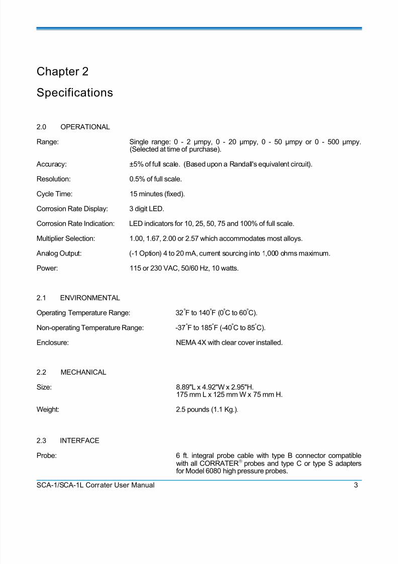
2.0 OPERATIONAL
Range: Single range: 0 - 2 µmpy, 0 - 20 µmpy, 0 - 50 µmpy or 0 - 500 µmpy.(Selected at time of purchase).
Accuracy: ±5% of full scale. (Based upon a Randall's equivalent circuit).
Resolution: 0.5% of full scale.
Cycle Time: 15 minutes (fixed).Corrosion Rate Display: 3 digit LED.
Corrosion Rate Indication: LED indicators for 10, 25, 50, 75 and 100% of full scale.
Multiplier Selection: 1.00, 1.67, 2.00 or 2.57 which accommodates most alloys.
Analog Output: (-1 Option) 4 to 20 mA, current sourcing into 1,000 ohms maximum.
Power: 115 or 230 VAC, 50/60 Hz, 10 watts.
2.1 ENVIRONMENTAL
Operating Temperature Range: 32ºF to 140ºF (0ºC to 60ºC).
Non-operating Temperature Range: -37ºF to 185ºF (-40ºC to 85ºC).
Enclosure: NEMA 4X with clear cover installed.
2.2 MECHANICAL
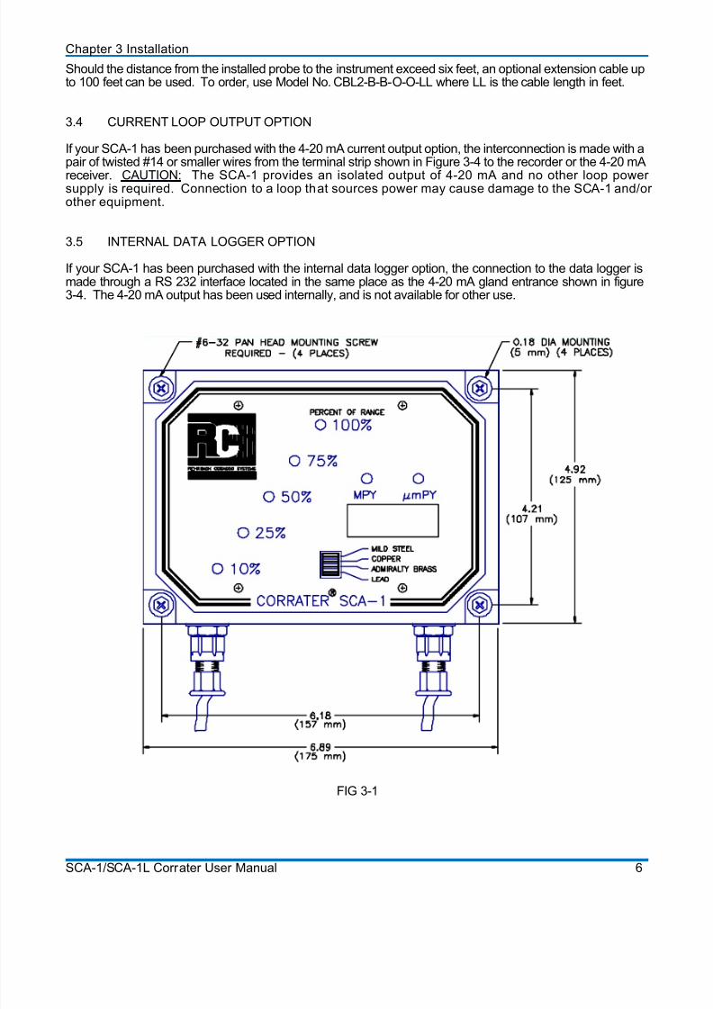
Size: 8.89"L x 4.92"W x 2.95"H.
175 mm L x 125 mm W x 75 mm H.
Weight: 2.5 pounds (1.1 Kg.).
2.3 INTERFACE
Probe: 6 ft. integral probe cable with type B connector compatiblewith all CORRATER® probes and type C or type S adaptersfor Model 6080 high pressure probes.
SCA-1/SCA-1L Corrater User Manual 3
8/20/2019 SCA-1 LPR Corrosion Rate Instrument Manual
http://slidepdf.com/reader/full/sca-1-lpr-corrosion-rate-instrument-manual 10/33
Chapter 2 Specifications
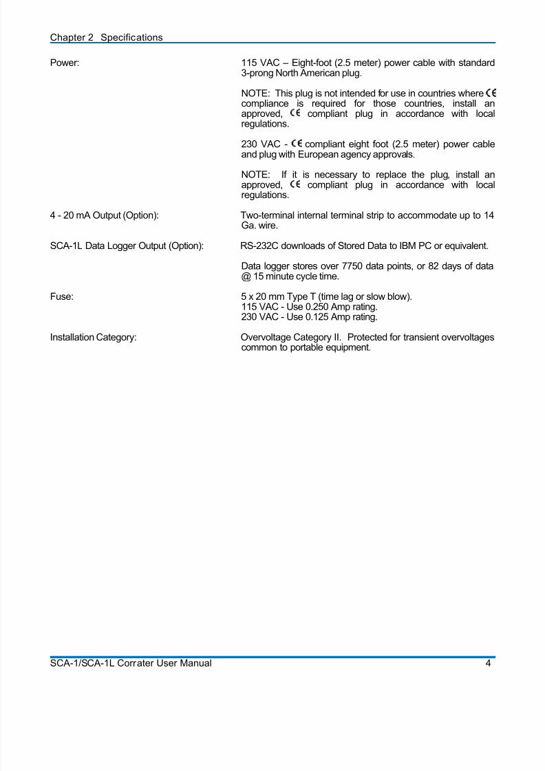
Power: 115 VAC – Eight-foot (2.5 meter) power cable with standard3-prong North American plug.
NOTE: This plug is not intended for use in countries wherecompliance is required for those countries, install anapproved, compliant plug in accordance with localregulations.
230 VAC - compliant eight foot (2.5 meter) power cableand plug with European agency approvals.
NOTE: If it is necessary to replace the plug, install anapproved, compliant plug in accordance with localregulations.
4 - 20 mA Output (Option): Two-terminal internal terminal strip to accommodate up to 14Ga. wire.
SCA-1L Data Logger Output (Option): RS-232C downloads of Stored Data to IBM PC or equivalent.
Data logger stores over 7750 data points, or 82 days of data@ 15 minute cycle time.
Fuse: 5 x 20 mm Type T (time lag or slow blow).115 VAC - Use 0.250 Amp rating.230 VAC - Use 0.125 Amp rating.
Installation Category: Overvoltage Category II. Protected for transient overvoltagescommon to portable equipment.
SCA-1/SCA-1L Corrater User Manual 4
8/20/2019 SCA-1 LPR Corrosion Rate Instrument Manual
http://slidepdf.com/reader/full/sca-1-lpr-corrosion-rate-instrument-manual 11/33
Chapter 3
Installation
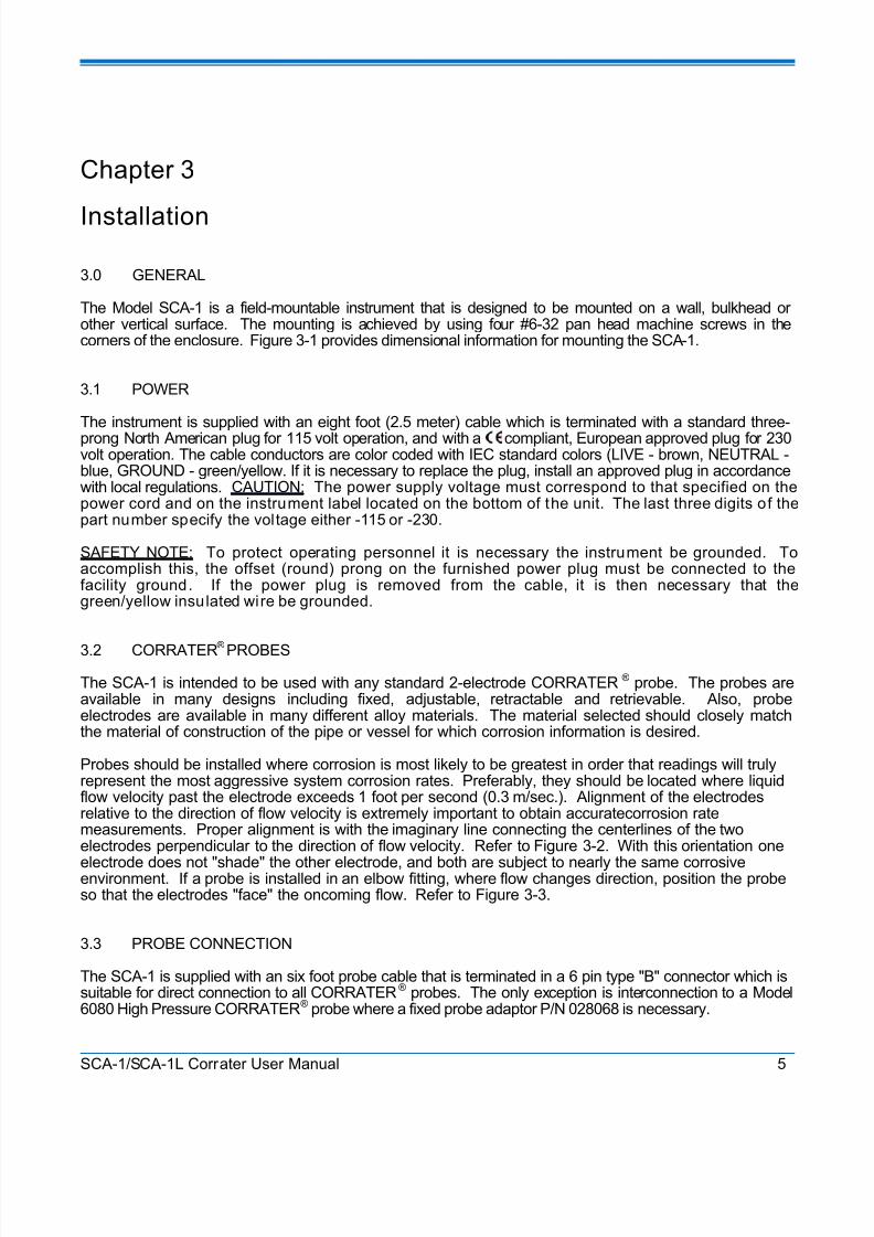
3.0 GENERAL
The Model SCA-1 is a field-mountable instrument that is designed to be mounted on a wall, bulkhead orother vertical surface. The mounting is achieved by using four #6-32 pan head machine screws in thecorners of the enclosure. Figure 3-1 provides dimensional information for mounting the SCA-1.
3.1 POWER
The instrument is supplied with an eight foot (2.5 meter) cable which is terminated with a standard three-prong North American plug for 115 volt operation, and with a compliant, European approved plug for 230volt operation. The cable conductors are color coded with IEC standard colors (LIVE - brown, NEUTRAL -blue, GROUND - green/yellow. If it is necessary to replace the plug, install an approved plug in accordancewith local regulations. CAUTION: The power supply voltage must correspond to that specified on thepower cord and on the instrument label located on the bottom of the unit. The last three digits of thepart number specify the voltage either -115 or -230.
SAFETY NOTE: To protect operating personnel it is necessary the instrument be grounded. Toaccomplish this, the offset (round) prong on the furnished power plug must be connected to thefacility ground. If the power plug is removed from the cable, it is then necessary that thegreen/yellow insulated wire be grounded.
3.2 CORRATER® PROBES
The SCA-1 is intended to be used with any standard 2-electrode CORRATER® probe. The probes areavailable in many designs including fixed, adjustable, retractable and retrievable. Also, probeelectrodes are available in many different alloy materials. The material selected should closely matchthe material of construction of the pipe or vessel for which corrosion information is desired.
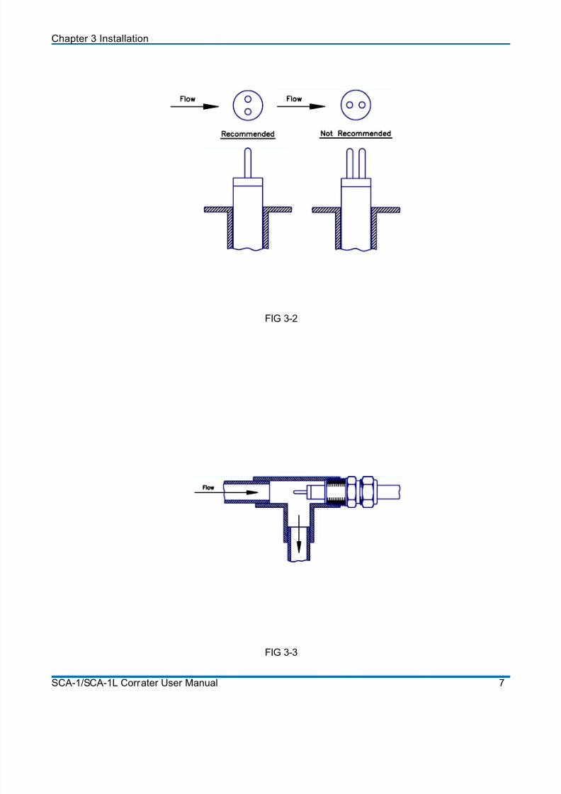
Probes should be installed where corrosion is most likely to be greatest in order that readings will trulyrepresent the most aggressive system corrosion rates. Preferably, they should be located where liquidflow velocity past the electrode exceeds 1 foot per second (0.3 m/sec.). Alignment of the electrodesrelative to the direction of flow velocity is extremely important to obtain accuratecorrosion ratemeasurements. Proper alignment is with the imaginary line connecting the centerlines of the twoelectrodes perpendicular to the direction of flow velocity. Refer to Figure 3-2. With this orientation one
electrode does not "shade" the other electrode, and both are subject to nearly the same corrosiveenvironment. If a probe is installed in an elbow fitting, where flow changes direction, position the probeso that the electrodes "face" the oncoming flow. Refer to Figure 3-3.
3.3 PROBE CONNECTION
The SCA-1 is supplied with an six foot probe cable that is terminated in a 6 pin type "B" connector which issuitable for direct connection to all CORRATER® probes. The only exception is interconnection to a Model6080 High Pressure CORRATER® probe where a fixed probe adaptor P/N 028068 is necessary.
SCA-1/SCA-1L Corrater User Manual 5
8/20/2019 SCA-1 LPR Corrosion Rate Instrument Manual
http://slidepdf.com/reader/full/sca-1-lpr-corrosion-rate-instrument-manual 12/33
Chapter 3 Installation
Should the distance from the installed probe to the instrument exceed six feet, an optional extension cable upto 100 feet can be used. To order, use Model No. CBL2-B-B-O-O-LL where LL is the cable length in feet.
3.4 CURRENT LOOP OUTPUT OPTION
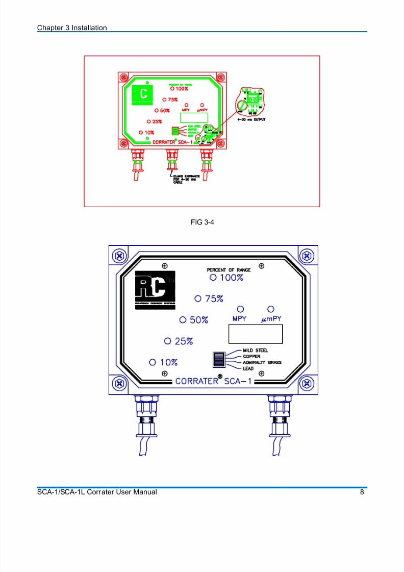
If your SCA-1 has been purchased with the 4-20 mA current output option, the interconnection is made with apair of twisted #14 or smaller wires from the terminal strip shown in Figure 3-4 to the recorder or the 4-20 mA
receiver. CAUTION: The SCA-1 provides an isolated output of 4-20 mA and no other loop powersupply is required. Connection to a loop that sources power may cause damage to the SCA-1 and/orother equipment.
3.5 INTERNAL DATA LOGGER OPTION
If your SCA-1 has been purchased with the internal data logger option, the connection to the data logger ismade through a RS 232 interface located in the same place as the 4-20 mA gland entrance shown in figure3-4. The 4-20 mA output has been used internally, and is not available for other use.
FIG 3-1
SCA-1/SCA-1L Corrater User Manual 6
8/20/2019 SCA-1 LPR Corrosion Rate Instrument Manual
http://slidepdf.com/reader/full/sca-1-lpr-corrosion-rate-instrument-manual 13/33
8/20/2019 SCA-1 LPR Corrosion Rate Instrument Manual
http://slidepdf.com/reader/full/sca-1-lpr-corrosion-rate-instrument-manual 14/33
Chapter 3 Installation
FIG 3-4
SCA-1/SCA-1L Corrater User Manual 8
8/20/2019 SCA-1 LPR Corrosion Rate Instrument Manual
http://slidepdf.com/reader/full/sca-1-lpr-corrosion-rate-instrument-manual 15/33
Chapter 4
Operation
4.0 GENERAL
The Model SCA-1 is intended for continuous corrosion monitoring of cooling water systems and thereforedoes not require operator actions for operation other than those required for setup.
4.1 INITIAL SETUP
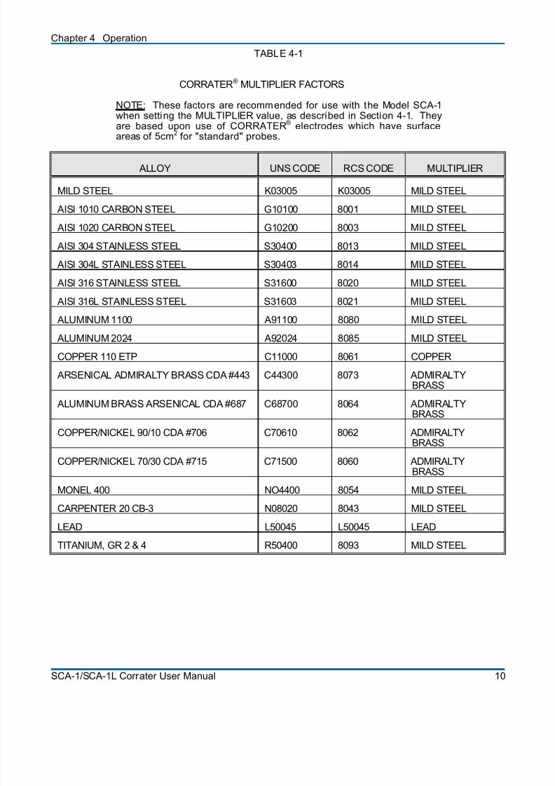
After installation, only the front panel DIP switch needs to be set for the multiplier for the alloy in use. Whenthe SCA-1 testing is completed at RCS, the multiplier is set to the MILD STEEL position. Please refer toTable 4-1 (see next page) for recommended multiplier selections. If an alternate selection is required,remove the clear cover from the SCA-1 and depress the RIGHT side of the appropriate multiplier selectionwith a pen or pencil point until it clicks. The remaining three switches should be depressed on the LEFT side. This is all that is required for the initial setup. NOTE: If the SCA-1 is powered when the multipl ier isselected, power must be interrupted for approximately 10 seconds for the change to be accepted.
4.2 STARTUP
Connect the CORRATER® probe to the SCA-1 and make sure the probe is properly inserted in the flow.Power can now be applied to the SCA-1 and the measurement cycle will be initiated. The first corrosion ratereading and percentage of full scale indication will be available after the first 15 minute measurement cycle.
The display and indicators will be updated every 15 minutes thereafter. Should the measured corrosion rateexceed the full scale of the range of the instrument, the display will show "or", indicating over range. After thecorrosion rate decreases to an in-range value, the display will return to showing the corrosion rate value inengineering units.
SCA-1/SCA-1L Corrater User Manual 9
8/20/2019 SCA-1 LPR Corrosion Rate Instrument Manual
http://slidepdf.com/reader/full/sca-1-lpr-corrosion-rate-instrument-manual 16/33
Chapter 4 Operation
TABLE 4-1
CORRATER® MULTIPLIER FACTORS
NOTE: These factors are recommended for use with the Model SCA-1when setting the MULTIPLIER value, as described in Section 4-1. Theyare based upon use of CORRATER® electrodes which have surface
areas of 5cm2
for "standard" probes.
ALLOY UNS CODE RCS CODE MULTIPLIER
MILD STEEL K03005 K03005 MILD STEEL
AISI 1010 CARBON STEEL G10100 8001 MILD STEEL
AISI 1020 CARBON STEEL G10200 8003 MILD STEEL
AISI 304 STAINLESS STEEL S30400 8013 MILD STEEL
AISI 304L STAINLESS STEEL S30403 8014 MILD STEEL
AISI 316 STAINLESS STEEL S31600 8020 MILD STEEL
AISI 316L STAINLESS STEEL S31603 8021 MILD STEEL
ALUMINUM 1100 A91100 8080 MILD STEEL
ALUMINUM 2024 A92024 8085 MILD STEEL
COPPER 110 ETP C11000 8061 COPPER
ARSENICAL ADMIRALTY BRASS CDA #443 C44300 8073 ADMIRALTYBRASS
ALUMINUM BRASS ARSENICAL CDA #687 C68700 8064 ADMIRALTY
BRASS
COPPER/NICKEL 90/10 CDA #706 C70610 8062 ADMIRALTYBRASS
COPPER/NICKEL 70/30 CDA #715 C71500 8060 ADMIRALTYBRASS
MONEL 400 NO4400 8054 MILD STEEL
CARPENTER 20 CB-3 N08020 8043 MILD STEEL
LEAD L50045 L50045 LEAD
TITANIUM, GR 2 & 4 R50400 8093 MILD STEEL
SCA-1/SCA-1L Corrater User Manual 10
8/20/2019 SCA-1 LPR Corrosion Rate Instrument Manual
http://slidepdf.com/reader/full/sca-1-lpr-corrosion-rate-instrument-manual 17/33
Chapter 5
Maintenance
5.0 INTRODUCTION
Routine maintenance on the SCA-1 is not required. There is no initial calibration or periodic calibrationrequired.
Probes, however, require regular maintenance and scheduled replacement in order to perform satisfactorily.Probes are covered in sections 5.2 for probe replacement, 5.3 for electrode cleaning, and 5.4 for electrodereplacement. If a problem with the SCA-1 is suspected, section 5.1 describes tests to verify proper operationof the instrument.
5.1 USER TEST
If a problem in the instrument is suspected, you may perform the following series of tests to verify operationof the instrument and isolate the fault: 1) Remove power from the instrument; 2) Remove the protectiveplastic cover, note the position of the multiplier switch, then change the switch to the mild steel selection; 3)disconnect the integral probe cable from the probe or probe extension cable and attach the test probe whichwas supplied with the instrument (Part No. 011001 for 2 MPY and 50 UMPY units, 011000-5 for 20 MPY and500 UMPY units) to the probe cable; restore power to the instrument and wait for the fifteen-minute readingcycle to be completed. If the reading agrees with the value printed on the test probe, then the problem isprobably in the extension cable, if used, or in the probe itself. NOTE: You must wait a full 15 minutes forthe instrument to complete a measurement cycle wi th the multiplier in the MILD STEEL setting.
If the instrument read the test probe correctly when attached directly and a probe-to-instrument extensioncable is in use, you may repeat the test with the test probe moved to the end of the extension cable and theinstrument reconnected to the extension cable. Again, the reading should agree with the reading of the testprobe when no cable is attached. If both of these tests pass, then the SCA-1, the cable, and all theconnectors are o.k. Any remaining problems are likely caused by the probe or the process itself. A foulingproblem, for example, can bridge the electrodes and yield readings that are off scale.
NOTE: Be sure to return the multiplier switch to its original position after testing.
5.2 PROBE REPLACEMENT
Although the SCA-1 will last indefinitely, the probes and probe elements that are used with it have a
very definite life span, and must be replaced on a regular basis. A probe element replacementschedule should be established with a criterion such as 1/32" (0.794 mm) loss of diameter.
5.3 ELECTRODE CLEANING
As supplied from the factory, CORRATER® electrodes have blasted surfaces and require no furthercleaning before they are used. However, should the electrodes become fouled with corrosion productsor other materials, they should be cleaned and polished to a dull shine with an emery cloth. Aftercleaning, the electrodes should be thoroughly degreased in a suitable solvent, and handled with a cleancloth or paper towel to prevent contamination.
SCA-1/SCA-1L Corrater User Manual 11
8/20/2019 SCA-1 LPR Corrosion Rate Instrument Manual
http://slidepdf.com/reader/full/sca-1-lpr-corrosion-rate-instrument-manual 18/33
Chapter 5 Maintenance
Electrodes should be replaced when the diameter is 1/32" (0.794 mm) less than the original. When installingnew or cleaned electrodes, handle them with a clean cloth or paper towel to avoid depositing anycontaminating oily film.
5.4 ELECTRODE REPLACEMENT
CORRATER
®
electrodes, when new, at 3/16" (4.76 mm) diameter by 1 1/4" (31.75 mm) long cylinders. Ascorrosion occures on the electrodes, their diameter decreases and at some point the reduced diameterbegins to significantly affect the accuracy of the corrosion readings. It is recommended that CORRATER®
electrodes be replaced when their diameter has been reduced to 5/32" (3.97 mm).
5.5 ELECTRODE PRETREATMENT
Pretreatment of the electrode is done in order to stabilize the instrument readings. Generally, a full strengthsample of the treatment chemical is used. The new electrodes are carefully placed into the solution for a 6-12 hour period and then threaded onto the probe and placed into service.
Because the electrodes have been saturated with the representative treatment solution, their equilibrationtime is lessened. The resulting data, generated from the readings, will show the corrosion trend earlier.
Without pretreatment, the equilibration time can be as much as one week.
5.6 CORRELATION WITH ELECTRODES AS COUPONS
Weigh the electrodes in the same manner as a coupon would be weighed, on a balance graduated to0.0001g before placing them in service. The coupon should be placed into service at the same time. After a30 or 60 day period, remove both, clean them and analyze them in the same manner. The readings from theinstrument integrated over a period of time, and the data from the electrodes and coupons should correlate.
SCA-1/SCA-1L Corrater User Manual 12
8/20/2019 SCA-1 LPR Corrosion Rate Instrument Manual
http://slidepdf.com/reader/full/sca-1-lpr-corrosion-rate-instrument-manual 19/33
Chapter 6
Warranty
6.0 SPECIAL WARRANTY POLICY FOR THE SCA-1 CORRATER®
This warranty applies to the following Rohrback Cosasco Systems equipment and systems sold in the UnitedStates by Rohrback Cosasco Systems.
SCA-1 CORRATER®
Subject to the conditions herein, Rohrback Cosasco Systems agrees, upon prompt notification, to correct
either by repair, or at its election, by replacement, any defect of material or workmanship which developswithin ninety (90) days after startup, or six (6) months from date of shipment to the original purchaser,whichever comes first, provided that an investigation and inspection by Rohrback Cosasco Systemsdiscloses that such defect developed under normal and proper use.
6.1 CONDITIONS
6.1.1 Rohrback Cosasco Systems will provide a field service engineer, if the customer requiresfield inspection, at non-reimbursable current standard rates plus all reasonable travel andliving expenses or,
6.1.2 All items claimed defective may be returned to Rohrback Cosasco Systems, or an authorizedfield service center, transportation charges prepaid, and will be returned to the customer with
the transportation charges collect.
6.1.3 Rohrback Cosasco Systems shall be released from all obligations under its Warranty if theinstrument or parts thereof are physically abused, damaged, lost, or are damaged byimproper installation, connections, start-up, application or for other reasons beyond thecontrol and responsibility of Rohrback Cosasco Systems. Further, Rohrback CosascoSystems shall be released from all obligations under its Warranty in the event repairs ormodifications are made by persons other than its own or authorized service personnel, unlesssuch repairs by others are made with written consent of Rohrback Cosasco Systems, orunless such repair is merely the installation or a new plug-in component or standardaccessory supplied by Rohrback Cosasco Systems for this purpose. What constitutesdamage covered or not covered under the conditions of this Warranty shall be determinedsolely by Rohrback Cosasco Systems, after Rohrback Cosasco Systems is in possession of
all facts it judges pertinent and pertinent and necessary to make such a determination.
6.1.4 Rohrback Cosasco Systems makes no Warranty concerning components or accessories(such as recorders or computers) not manufactured by it. However, in the event of the failureof any component or accessory not manufactured by Rohrback Cosasco Systems, RohrbackCosasco Systems will give reasonable assistance to the customer in obtaining from therespective manufacturer whatever adjustment is reasonable in the light of the manufacturer'sown Warranty. Except to the extent expressly stated in this agreement, Rohrback CosascoSystems makes no Warranty, express or implied (either in fact of by operation of law),statutory or otherwise; and except to the extent stated above, Rohrback Cosasco Systems
SCA-1/SCA-1L Corrater User Manual 13
8/20/2019 SCA-1 LPR Corrosion Rate Instrument Manual
http://slidepdf.com/reader/full/sca-1-lpr-corrosion-rate-instrument-manual 20/33
Chapter 6 Warranty
shall have no liability under Warranty, express or implied (either in fact or by operation of law),statutory or otherwise.
6.2 OTHER PRODUCTS
All other products, components, and accessories such as probes will be warranted in accordance with
the conditions printed on the reverse of Rohrback Cosasco Systems' standard quotation form.
SCA-1/SCA-1L Corrater User Manual 14
8/20/2019 SCA-1 LPR Corrosion Rate Instrument Manual
http://slidepdf.com/reader/full/sca-1-lpr-corrosion-rate-instrument-manual 21/33
Chapter 7
SCA-1L Internal Data Logger Option
7.0 GENERAL
As an option, the SCA-1 is provided with an internally mounted HOBO® H8 data logger to store the 4-20 mAoutput of the SCA-1.
The BoxCar ® Pro software must be used to configure and retrieve data from the data logger. The BoxCar ®
Pro User’s manual is supplied with the software, and is the primary reference for software operation. Thedetails provided below are meant as a guide to assist in the set up of the data logger and analysis of thedata.
HOBO® and BoxCar ® Pro are registered trademarks of Onset Computer Corporation.
7.1 Data Logger Power Supply
Three triple A (AAA) batteries are used to power the data logger inside the SCA-1. These batteries shouldprovide power to the data logger for a minimum of one year. When launching the data logger, a “fuel supply”gage on the PC screen indicates the power left in the battery. It is recommended that the batteries bereplaced when the fuel gage reads ¼ full.
To change the batteries, the following is recommended:
1) DISCONNECT POWER FROM THE SCA-1! 2) Remove the four corner screws and the then the cover on the unit.3) Remove the four face plate screws.4) Gently lift the faceplate out of the box.5) Turn face plate over, the batteries will be plainly visible.6) Replace batteries.7) Place faceplate back in position.8) Replace the four faceplate screws.9) Place the cover back on the unit, and install the four corner screws.
7.2 Data Logger Configuration
The Data Logger is configured using the BoxCar ®
Pro Software. Follow the HOBO®
H8 Quick Startdirections in the BoxCar ® Pro User’s manual. The following settings should be used during the launchsequence (Choose Launch From the Logger Pull Down Screen):
SCA-1/SCA-1L Corrater User Manual 15
8/20/2019 SCA-1 LPR Corrosion Rate Instrument Manual
http://slidepdf.com/reader/full/sca-1-lpr-corrosion-rate-instrument-manual 22/33
Chapter 7 SCA-1L Internal Data Logger Option
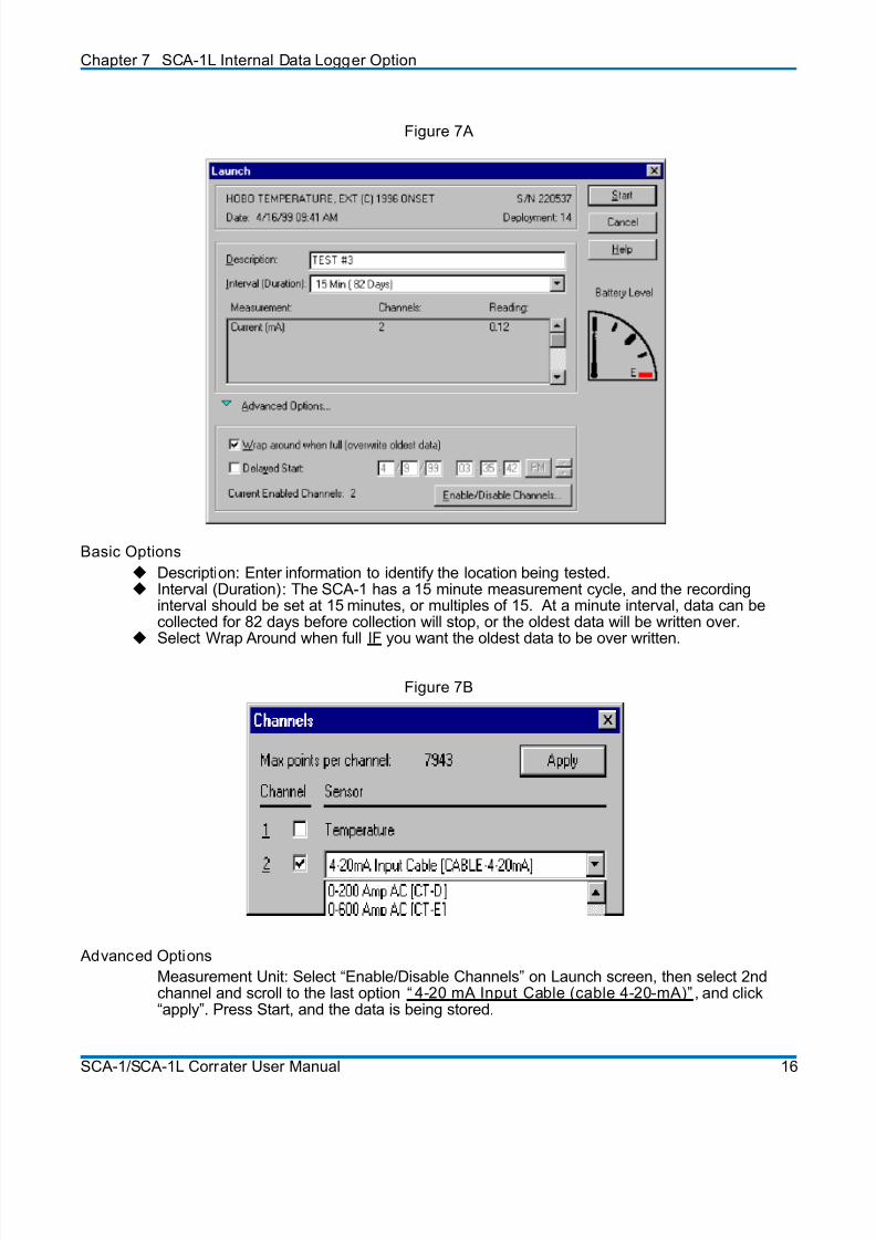
Figure 7A
B
asic Options
Description: Enter information to identify the location being tested. Interval (Duration): The SCA-1 has a 15 minute measurement cycle, and the recording
interval should be set at 15 minutes, or multiples of 15. At a minute interval, data can becollected for 82 days before collection will stop, or the oldest data will be written over.
Select Wrap Around when full IF you want the oldest data to be over written.
Figure 7B
Advanced Options
Measurement Unit: Select “Enable/Disable Channels” on Launch screen, then select 2ndchannel and scroll to the last option “ 4-20 mA Input Cable (cable 4-20-mA)” , and click“apply”. Press Start, and the data is being stored.
SCA-1/SCA-1L Corrater User Manual 16
8/20/2019 SCA-1 LPR Corrosion Rate Instrument Manual
http://slidepdf.com/reader/full/sca-1-lpr-corrosion-rate-instrument-manual 23/33
Chapter 7 SCA-1L Internal Data Logger Option
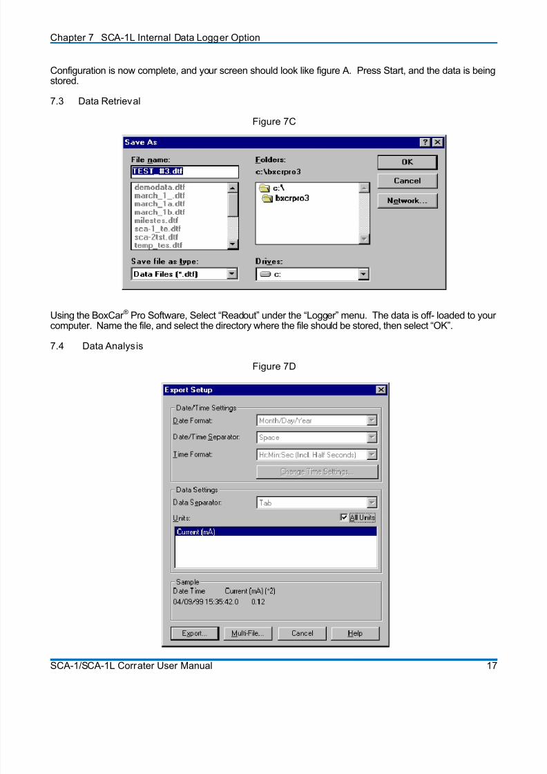
Configuration is now complete, and your screen should look like figure A. Press Start, and the data is beingstored.
7.3 Data Retrieval
Figure 7C
Using the BoxCar ® Pro Software, Select “Readout” under the “Logger” menu. The data is off- loaded to yourcomputer. Name the file, and select the directory where the file should be stored, then select “OK”.
7.4 Data Analysis
Figure 7D
SCA-1/SCA-1L Corrater User Manual 17
8/20/2019 SCA-1 LPR Corrosion Rate Instrument Manual
http://slidepdf.com/reader/full/sca-1-lpr-corrosion-rate-instrument-manual 24/33
Chapter 7 SCA-1L Internal Data Logger Option
The data can be scaled and labeled in Microsoft Excel® or Lotus 123®. To export the data to a spreadsheetprogram, choose “Export” under the “File Menu”, and select the appropriate software program. Next, click onthe “export” box, and enter the file name and destination folder. The file is exported as a tab delimited “.txt”file. This step must be done when the file is open in the Boxcar software.
Open the spreadsheet program, and then open the exported file. The exported file will have a “.txt” suffix,and you may need to select “all files”, after selecting open in the spreadsheet program.
After opening the file, follow the spreadsheet prompts of the import wizard choosing “Delimited” as theseparation type, and “Tab” as the delimiter.
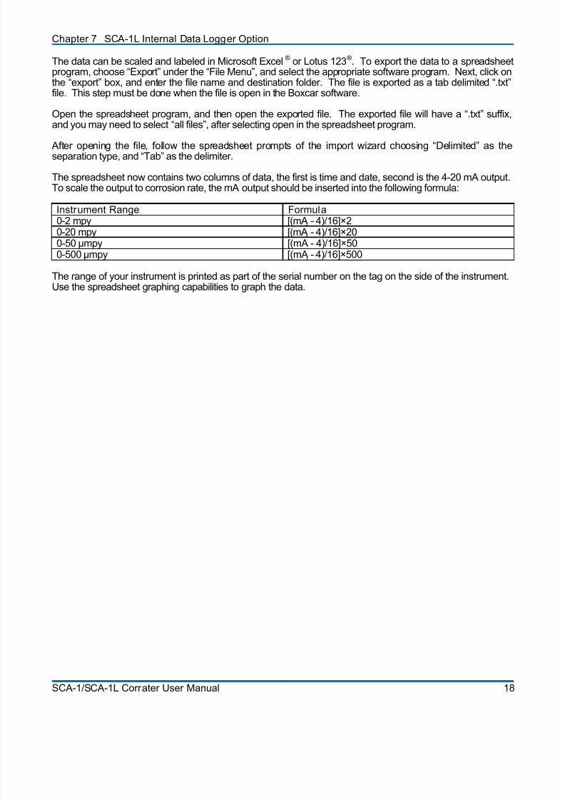
The spreadsheet now contains two columns of data, the first is time and date, second is the 4-20 mA output.To scale the output to corrosion rate, the mA output should be inserted into the following formula:
Instrument Range Formula0-2 mpy [(mA - 4)/16]×20-20 mpy [(mA - 4)/16]×200-50 µmpy [(mA - 4)/16]×500-500 µmpy [(mA - 4)/16]×500
The range of your instrument is printed as part of the serial number on the tag on the side of the instrument.Use the spreadsheet graphing capabilities to graph the data.
SCA-1/SCA-1L Corrater User Manual 18
8/20/2019 SCA-1 LPR Corrosion Rate Instrument Manual
http://slidepdf.com/reader/full/sca-1-lpr-corrosion-rate-instrument-manual 25/33
Appendix A
Theory of Operation of CORRATER®
Systems
THEORY OF OPERATION FOR THE POLARIZATION RESISTANCE METHOD OF CORROSIONRATE MEASUREMENT
Introduction
Corrosion is an electrochemical process generally occurring when a metal is in contact with an electricallyconductive liquid such as water solution.
At the interference between the metal and the liquid, the immediate corrosive reaction is that some metalatoms at the surface become positively charged and give up electrons into the metal and become positiveions (cations) in the liquid. Since the metal cannot accumulate electrons, a second immediate reaction mustsimultaneously take place. The metal must conduct electrons to some specie(s) in the liquid resulting ineither the neutralization of positive ions or the creation of negative ions (anions). The first reaction (whereelectrons enter the metal is "anodic" and is called oxidation, and the second reaction (where electrons leavethe metal) is "cathodic" and is called reduction. On a metal surface, the anodic and cathodic areas aregenerally microscopic in size, and are unstable in that they move around as local interfacial conditionschange.
An example of an anodic reaction, involving iron is:
Iron Oxidation Fe→ Fe+2 + 2e
Examples of cathodic reactions which occur are:
Hydrogen evolution 2H+ + 2e→ H2
Oxygen reduction 02 + 4H+ + 4e→ 2 H20or 02 + 2 H20 + 4e→ 4 0H-
As stated, the above are the immediate anodic and cathodic electrochemical reactions which occur.Subsequent reactions take place, for instance, ferrous ions may join with hydroxyl ions to form ferroushydroxide (Fe(0H)2). Several other ion products may also be formed, such as ferrous oxide (Fe0) and ferricoxide (Fe203), which are commonly referred to as "rust".
The rate of naturally occurring electrochemical oxidation (corrosion) is dependent upon a multitude of
parameters including metal composition, homogeneity, intergranular structure, surface finish, oxidationproducts, liquid temperature, pH, dissolved oxygen and other gasses, flow velocity, and certainly thechemical content and physical characteristics of the liquid itself.
The polarization resistance method of measuring corrosion rate comprises a means to measure the electrical(electron-ion interchange) resistance at the interface between a metal element of known surface area and aliquid, without significantly disturbing the natural conditions of that interface. The metal element, or the "testelement", which is inserted into the liquid must closely match the material of construction (pipe or vessel) forwhich the corrosion rate information is required. As will be shown, the measured interfacial resistance(herein called "polarization resistance") is an inverse function of the corrosion rate.
SCA-1/SCA-1L Corrater User Manual 19

8/20/2019 SCA-1 LPR Corrosion Rate Instrument Manual
http://slidepdf.com/reader/full/sca-1-lpr-corrosion-rate-instrument-manual 26/33
Appendix A Theory of Operation of Corrater ® Systems
The relationship among the Electrochemical Reactions, Corrosion Current, Polarization Resistance, andCorrosion Rate
Because the metal undergoing the corrosive (anodic) action cannot accumulate electrons, the amount ofcathodic reaction (electrons released) must exactly equal the amount of anodic reaction (electrons acceptedwhen the metal is in its natural state - not connected to an external source of current. In other words, at thenatural corrosion potential, Ecorr , the net reducing current, iR, must equal the net oxidizing current, i0. Thus:
iΟ i O at E corr iΟ i O at E corr
Also, by definition, the corrosion current, icorr , is equal to the net oxidizing current; thus, at the naturalcorrosion potential, Ecorr :
icorr iΟ iicorr iΟ i
Unfortunately, icorr , which is proportional to corrosion rate, cannot be directly measured. However, if a metaltest element of known surface area were inserted into a liquid, and another metal element were also insertedinto the liquid, an electrical current can be forced by external means between the test element to the other
element. When this is done, the potential of the test element is forced to a value other than Ecorr . Alsobecause of externally supplied electrons to or from the test element, iR is no longer equal to i0. Under thiscondition, a current, imeas, can be measured and
imeas iΟ i Oimeas iΟ i O
Depending upon the direction of the supplied current, the test element is made either more anodic or morecathodic.
The voltage change of the test element from Ecorr is called the polarization potential or overvoltage,∆ E; thus,
∆ E E app E corr ∆ E E app E corr
where Eapp is the voltage applied which was required to cause the measured current, imeas. If the polarizationpotential is kept small so as not to disturb significantly the natural corrosion process, the overvoltage, ∆ E, islinearly related to the measured current, imeas. Their ratio ∆ E/imeas is referred to as the "polarizationresistance", Rp, of the test element.
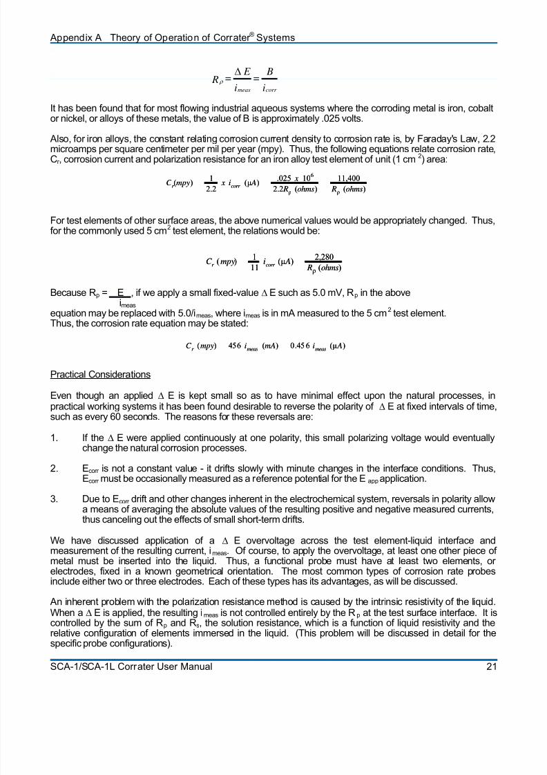
Theoretical work published by M. Stern and A.L. Geary in 1957 demonstrated that polarization resistance isrelated to corrosion current by this equation:
Rρ B
a B
c
2.3 icorr
( Ba Bc) Rρ
Ba B
c
2.3 icorr
( Ba Bc)
where Ba and Bc are the anodic and cathodic slopes of plots of the log of current vs. applied voltage,respectively, in the units of volts (per decade of current change). These slopes are usually referred to as"Tafel Slopes". Often the symbol "B" is used to represent the combined proportionality function. Thus,
Bc)+(Ba2.3
B B = B
ca
and
SCA-1/SCA-1L Corrater User Manual 20
8/20/2019 SCA-1 LPR Corrosion Rate Instrument Manual
http://slidepdf.com/reader/full/sca-1-lpr-corrosion-rate-instrument-manual 27/33
Appendix A Theory of Operation of Corrater ® Systems
i
B =
i
E = R
corr meas
∆ ρ
It has been found that for most flowing industrial aqueous systems where the corroding metal is iron, cobaltor nickel, or alloys of these metals, the value of B is approximately .025 volts.
Also, for iron alloys, the constant relating corrosion current density to corrosion rate is, by Faraday's Law, 2.2microamps per square centimeter per mil per year (mpy). Thus, the following equations relate corrosion rate,Cr , corrosion current and polarization resistance for an iron alloy test element of unit (1 cm2) area:
C r (mpy)
1
2.2 x icorr
(µ A) .025 x 10
6
2.2 Rρ (ohms)
11,400
Rρ (ohms)
C r (mpy)
1
2.2 x icorr
(µ A) .025 x 10
6
2.2 Rρ (ohms)
11,400
Rρ (ohms)
For test elements of other surface areas, the above numerical values would be appropriately changed. Thus,for the commonly used 5 cm2 test element, the relations would be:
C r (mpy) 1
11
icorr (µ A) 2,280
Rρ (ohms)
C r (mpy) 1
11
icorr (µ A) 2,280
Rρ (ohms)
Because Rp = E , if we apply a small fixed-value∆ E such as 5.0 mV, Rp in the aboveimeas
equation may be replaced with 5.0/imeas, where imeas is in mA measured to the 5 cm2 test element.Thus, the corrosion rate equation may be stated:
tions
C r (mpy) 456 i
meas (mA) 0.45 6 i
meas (µ A)C
r (mpy) 456 i
meas (mA) 0.45 6 i
meas (µ A)
Practical Considera
Even though an applied ∆ E is kept small so as to have minimal effect upon the natural processes, in
practical working systems it has been found desirable to reverse the polarity of ∆ E at fixed intervals of time,such as every 60 seconds. The reasons for these reversals are:
1. If the ∆ E were applied continuously at one polarity, this small polarizing voltage would eventuallychange the natural corrosion processes.
2. Ecorr is not a constant value - it drifts slowly with minute changes in the interface conditions. Thus,Ecorr must be occasionally measured as a reference potential for the Eapp application.
3. Due to Ecorr drift and other changes inherent in the electrochemical system, reversals in polarity allowa means of averaging the absolute values of the resulting positive and negative measured currents,thus canceling out the effects of small short-term drifts.
We have discussed application of a ∆ E overvoltage across the test element-liquid interface andmeasurement of the resulting current, imeas. Of course, to apply the overvoltage, at least one other piece ofmetal must be inserted into the liquid. Thus, a functional probe must have at least two elements, orelectrodes, fixed in a known geometrical orientation. The most common types of corrosion rate probesinclude either two or three electrodes. Each of these types has its advantages, as will be discussed.
An inherent problem with the polarization resistance method is caused by the intrinsic resistivity of the liquid.When a ∆ E is applied, the resulting imeas is not controlled entirely by the Rp at the test surface interface. It iscontrolled by the sum of Rp and Rs, the solution resistance, which is a function of liquid resistivity and therelative configuration of elements immersed in the liquid. (This problem will be discussed in detail for thespecific probe configurations).
SCA-1/SCA-1L Corrater User Manual 21
8/20/2019 SCA-1 LPR Corrosion Rate Instrument Manual
http://slidepdf.com/reader/full/sca-1-lpr-corrosion-rate-instrument-manual 28/33
Appendix A Theory of Operation of Corrater ® Systems
Two-electrode Probe
The metal elements (electrodes) in a two electrode probe are made of the same alloy (usually, from adjacentpieces of the same stock material) and to the same dimensions. The reason for closely matchingtheelectrodes is that they are both simultaneously functioning as test elements. After immersion into aflowing liquid system, the monitoring instrument measures the open-circuit potential, Eoc, between theelectrodes. (This voltage is the difference of their individual Ecorr values). To cause current to flow between
the electrodes, a fixed voltage is superimposed upon the Eoc value to cause a polarization potential acrossthe interface at each electrode - in the anodic direction at one electrode and in the cathodic direction at theother electrode. The resulting current is measured. After a waiting period of 60 seconds, the fixed voltagepolarity is reversed, and again the resulting current is measured over an identical waiting period. Thealgebraic difference of the two currents existing at the end of each waiting period is directly convertible into acorrosion rate reading, as described above. It should be noted that the superimposed fixed voltage is dividedbetween the interfaces at the two electrodes. For example, if 10 mV is superimposed, approximately 5 mVovervoltage is applied across each interface if the solution resistance, Rs, is negligible.
Because the open-circuit potential between the two "identical" electrodes is usually quite low, and alsobecause the measured current amplitudes in both directions are, in effect, averaged, it has been found thatlittle or nothing is gained by measuring Eoc and superimposing an activating voltage. Some instrumentationsystems take advantage of this knowledge and simply apply each polarity of the activating voltage directlyacross the two electrodes.
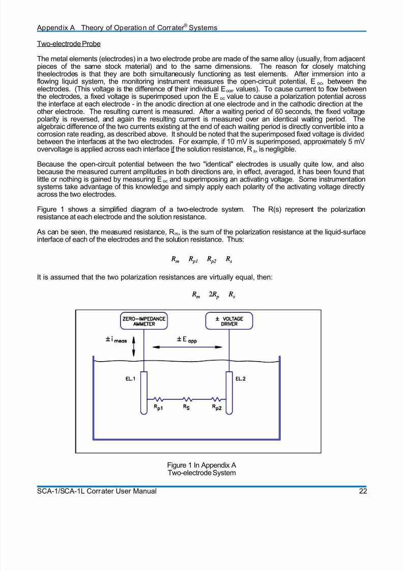
Figure 1 shows a simplified diagram of a two-electrode system. The R(s) represent the polarizationresistance at each electrode and the solution resistance.
As can be seen, the measured resistance, Rm, is the sum of the polarization resistance at the liquid-surfaceinterface of each of the electrodes and the solution resistance. Thus:
Rm R p1 R p2 Rs Rm R p1 R p2 Rs
It is assumed that the two polarization resistances are virtually equal, then:
Rm 2 R p Rs Rm 2 R p Rs
Figure 1 In Appendix ATwo-electrode System
SCA-1/SCA-1L Corrater User Manual 22
8/20/2019 SCA-1 LPR Corrosion Rate Instrument Manual
http://slidepdf.com/reader/full/sca-1-lpr-corrosion-rate-instrument-manual 29/33
Appendix A Theory of Operation of Corrater ® Systems
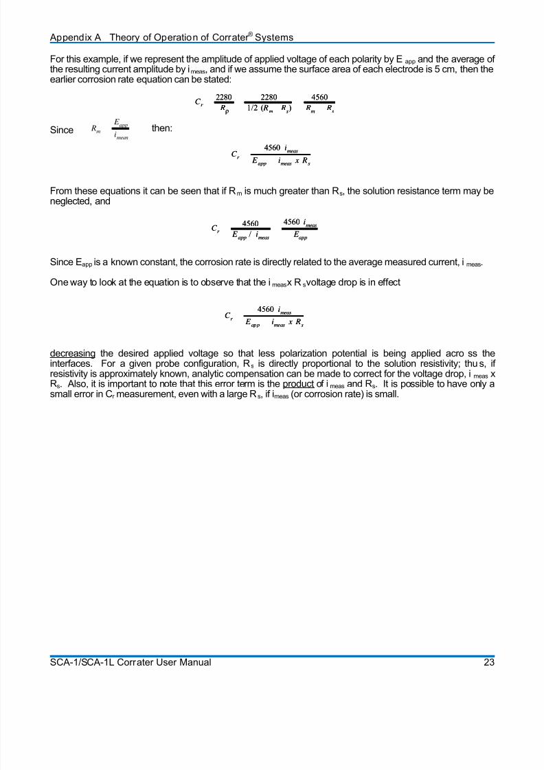
For this example, if we represent the amplitude of applied voltage of each polarity by Eapp and the average ofthe resulting current amplitude by imeas, and if we assume the surface area of each electrode is 5 cm, then theearlier corrosion rate equation can be stated:
ince
rom these equations it can be seen that if Rm is much greater than Rs, the solution resistance term may beeglected, and
Since E .
One way to look at the equation is to observe that the i x R voltage drop is in effect
decrea
C r
2280
Rρ
2280
1/2 ( Rm
Rs)
4560
Rm
Rs
C r
2280
Rρ
2280
1/2 ( Rm
Rs)
4560
Rm
Rs
C r
4560 imeas
E app imeas x Rs
C r
4560 imeas
E app imeas x Rs
r
S
Fn
C 4560
E app
/ imeas
4560 imeas
C E
appr
4560
E app
/ imeas
4560 imeas
E app
app is a known constant, the corrosion rate is directly related to the average measured current, imeas
meas s
C r
4560meas
E i x RC
r
i
app meas s
4560meas
E i x R
i
app meas s
Rm
E app
imean
then:
sing the desired applied voltage so that less polarization potential is being applied acrointerfaces. For a given probe configuration, Rs is directly proportional to the solution resistivity; thuresistivity is approximately known, analytic compensation can be made to correct for the voltage drop, i
ss thes, if
meas xRs. Also, it is important to note that this error term is the product of imeas and Rs. It is possible to have only asmall error in Cr measurement, even with a large Rs, if imeas (or corrosion rate) is small.
SCA-1/SCA-1L Corrater User Manual 23
8/20/2019 SCA-1 LPR Corrosion Rate Instrument Manual
http://slidepdf.com/reader/full/sca-1-lpr-corrosion-rate-instrument-manual 30/33
Appendix A Theory of Operation of Corrater ® Systems
SCA-1/SCA-1L Corrater User Manual 24
8/20/2019 SCA-1 LPR Corrosion Rate Instrument Manual
http://slidepdf.com/reader/full/sca-1-lpr-corrosion-rate-instrument-manual 31/33
Appendix B
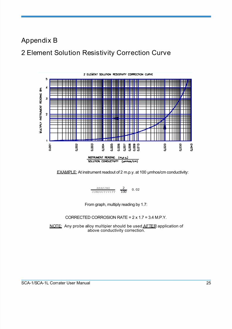
2 Element Solution Resistivity Correction Curve
EXAMPLE: At instrument readout of 2 m.p.y. at 100 µmhos/cm conductivity:
READING
CONDUCTIVITY
2
100 0. 02
From graph, multiply reading by 1.7:
CORRECTED CORROSION RATE = 2 x 1.7 = 3.4 M.P.Y.
NOTE: Any probe alloy multipier should be used AFTER application of
above conductivity correction.
SCA-1/SCA-1L Corrater User Manual 25
8/20/2019 SCA-1 LPR Corrosion Rate Instrument Manual
http://slidepdf.com/reader/full/sca-1-lpr-corrosion-rate-instrument-manual 32/33
Appendix B 2 Element Solution Resistivity Correct ion Curve
SCA-1/SCA-1L Corrater User Manual 26
8/20/2019 SCA-1 LPR Corrosion Rate Instrument Manual
http://slidepdf.com/reader/full/sca-1-lpr-corrosion-rate-instrument-manual 33/33
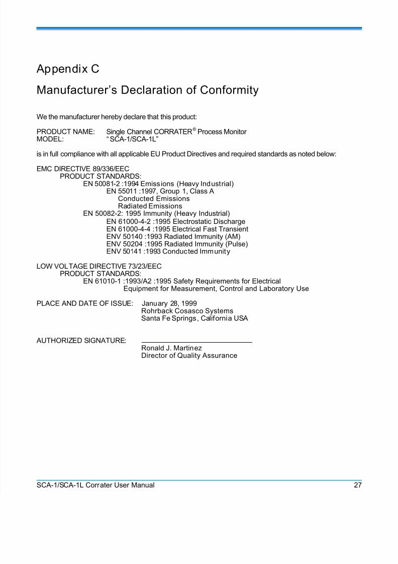
Appendix C
Manufacturer’s Declaration of Conformity
We the manufacturer hereby declare that this product:
PRODUCT NAME: Single Channel CORRATER® Process MonitorMODEL: “ SCA-1/SCA-1L”
is in full compliance with all applicable EU Product Directives and required standards as noted below:
EMC DIRECTIVE 89/336/EECPRODUCT STANDARDS:
EN 50081-2 :1994 Emissions (Heavy Industrial)EN 55011 :1997, Group 1, Class A
Conducted EmissionsRadiated Emissions
EN 50082-2: 1995 Immunity (Heavy Industrial)EN 61000-4-2 :1995 Electrostatic DischargeEN 61000-4-4 :1995 Electrical Fast TransientENV 50140 :1993 Radiated Immunity (AM)ENV 50204 :1995 Radiated Immunity (Pulse)ENV 50141 :1993 Conducted Immunity
LOW VOLTAGE DIRECTIVE 73/23/EECPRODUCT STANDARDS:
EN 61010-1 :1993/A2 :1995 Safety Requirements for ElectricalEquipment for Measurement, Control and Laboratory Use
PLACE AND DATE OF ISSUE: January 28, 1999Rohrback Cosasco SystemsSanta Fe Springs, California USA
AUTHORIZED SIGNATURE:Ronald J. MartinezDirector of Quality Assurance


![LPR 7320.1[1]](https://img.pdfslide.us/doc/110x75/577d36361a28ab3a6b927df7/lpr-732011.jpg)