Embed Size (px)
Citation preview
Manual No. 016-5033-052 Rev. B EC31812 08/18 1
SC1 TERRAGATOR B SERIES INSTALLATION GUIDE1. If SmarTrax™ is already installed on the machine, disconnect the SmarTrax ECU.
NOTE: Some of the SmarTrax cabling will need to be removed to install the SC1.
2. Install the SC1 (P/N 063-0174-009) on the mounting plate studs so the connectors are facing the short side of the SC1 mounting plate. Secure using the provided 1/4 - 20 nuts.
FIGURE 1. SC1 Mounting
3. Locate the SC1 mounting location on the right side of the seat base.
SC1 Mounting Plate
SC1
Mounting Hardware
Flange Bolts
Power/Can ECU Wakeup
2
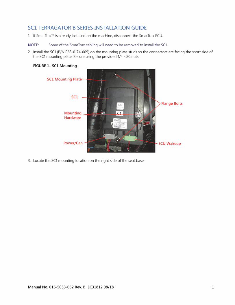
FIGURE 2. SC1 Mounting Location
4. Remove the two flange bolts on the right side of the seat base. 5. Install the SC1 Bracket using the flange bolts removed in the previous step.6. On the SC1 cable (P/N 115-0172-531), plug the gray power/can plug into mating receptacle on the SC1. 7. Plug the green ECU wakeup plug into the mating connector on the SC1. 8. On the outside of the cab, remove the exterior cable access panel.
FIGURE 3. Exterior Cable Access Panel
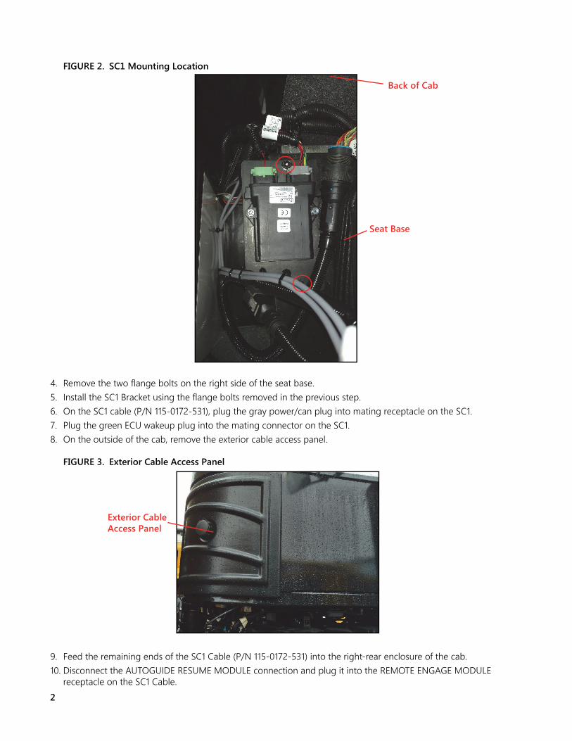
9. Feed the remaining ends of the SC1 Cable (P/N 115-0172-531) into the right-rear enclosure of the cab. 10. Disconnect the AUTOGUIDE RESUME MODULE connection and plug it into the REMOTE ENGAGE MODULE
receptacle on the SC1 Cable.
Seat Base
Back of Cab
Exterior Cable Access Panel
Manual No. 016-5033-052 Rev. B EC31812 08/18 3
FIGURE 4. REMOTE ENGAGE MODULE Connection
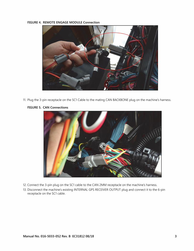
11. Plug the 3-pin receptacle on the SC1 Cable to the mating CAN BACKBONE plug on the machine’s harness.
FIGURE 5. CAN Connections
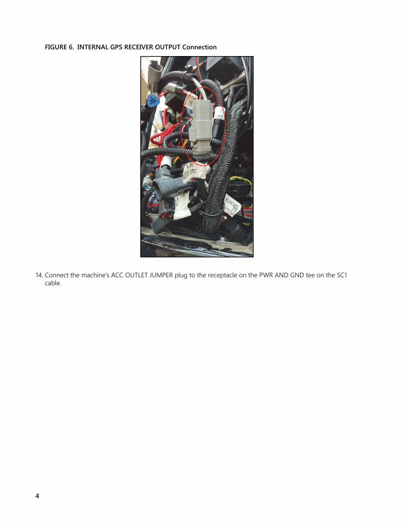
12. Connect the 3-pin plug on the SC1 cable to the CAN 2MM receptacle on the machine’s harness.13. Disconnect the machine’s existing INTERNAL GPS RECEIVER OUTPUT plug and connect it to the 6-pin
receptacle on the SC1 cable.
4
FIGURE 6. INTERNAL GPS RECEIVER OUTPUT Connection
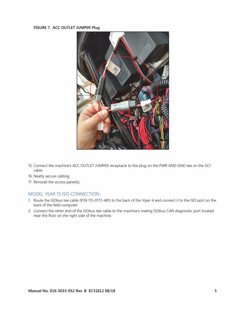
14. Connect the machine’s ACC OUTLET JUMPER plug to the receptacle on the PWR AND GND tee on the SC1 cable.
Manual No. 016-5033-052 Rev. B EC31812 08/18 5
FIGURE 7. ACC OUTLET JUMPER Plug
15. Connect the machine’s ACC OUTLET JUMPER receptacle to the plug on the PWR AND GND tee on the SC1 cable.
16. Neatly secure cabling.17. Reinstall the access panel(s).
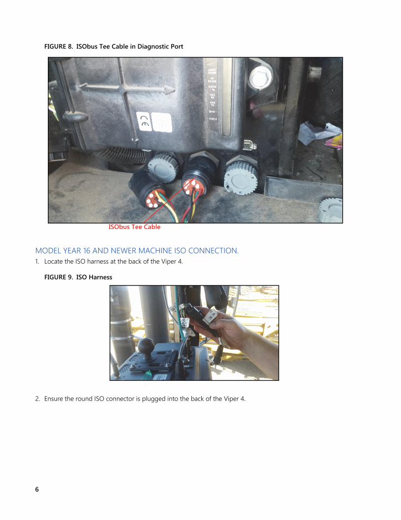
MODEL YEAR 15 ISO CONNECTION1. Route the ISObus tee cable (P/N 115-0172-481) to the back of the Viper 4 and connect it to the ISO port on the
back of the field computer. 2. Connect the other end of the ISObus tee cable to the machine’s mating ISObus CAN diagnostic port located
near the floor on the right side of the machine.
6
FIGURE 8. ISObus Tee Cable in Diagnostic Port
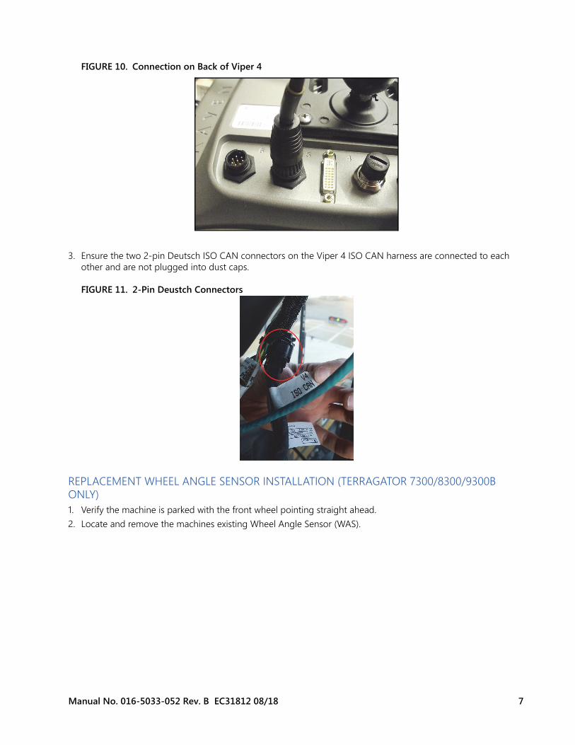
MODEL YEAR 16 AND NEWER MACHINE ISO CONNECTION. 1. Locate the ISO harness at the back of the Viper 4.
FIGURE 9. ISO Harness
2. Ensure the round ISO connector is plugged into the back of the Viper 4.
ISObus Tee Cable
Manual No. 016-5033-052 Rev. B EC31812 08/18 7
FIGURE 10. Connection on Back of Viper 4
3. Ensure the two 2-pin Deutsch ISO CAN connectors on the Viper 4 ISO CAN harness are connected to each other and are not plugged into dust caps.
FIGURE 11. 2-Pin Deustch Connectors
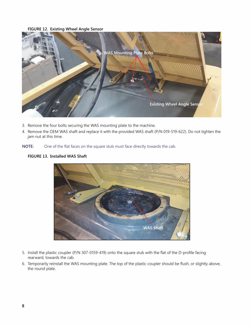
REPLACEMENT WHEEL ANGLE SENSOR INSTALLATION (TERRAGATOR 7300/8300/9300B ONLY)1. Verify the machine is parked with the front wheel pointing straight ahead.2. Locate and remove the machines existing Wheel Angle Sensor (WAS).
8
FIGURE 12. Existing Wheel Angle Sensor
3. Remove the four bolts securing the WAS mounting plate to the machine.4. Remove the OEM WAS shaft and replace it with the provided WAS shaft (P/N 019-519-622). Do not tighten the
jam nut at this time.
NOTE: One of the flat faces on the square stub must face directly towards the cab.
FIGURE 13. Installed WAS Shaft
5. Install the plastic coupler (P/N 307-0159-419) onto the square stub with the flat of the D-profile facing rearward, towards the cab.
6. Temporarily reinstall the WAS mounting plate. The top of the plastic coupler should be flush, or slightly above, the round plate.
Existing Wheel Angle Sensor
WAS Mounting Plate Bolts
WAS Shaft
Manual No. 016-5033-052 Rev. B EC31812 08/18 9
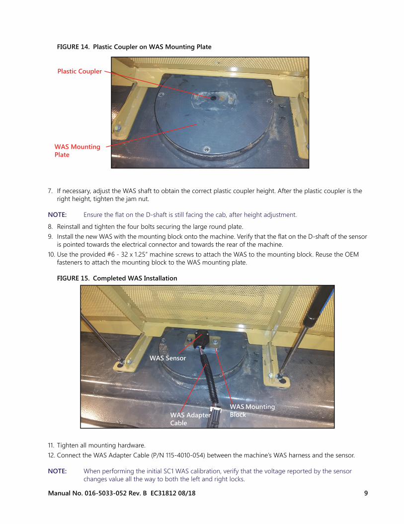
FIGURE 14. Plastic Coupler on WAS Mounting Plate
7. If necessary, adjust the WAS shaft to obtain the correct plastic coupler height. After the plastic coupler is the right height, tighten the jam nut.
NOTE: Ensure the flat on the D-shaft is still facing the cab, after height adjustment.
8. Reinstall and tighten the four bolts securing the large round plate.9. Install the new WAS with the mounting block onto the machine. Verify that the flat on the D-shaft of the sensor
is pointed towards the electrical connector and towards the rear of the machine.10. Use the provided #6 - 32 x 1.25” machine screws to attach the WAS to the mounting block. Reuse the OEM
fasteners to attach the mounting block to the WAS mounting plate.
FIGURE 15. Completed WAS Installation
11. Tighten all mounting hardware.12. Connect the WAS Adapter Cable (P/N 115-4010-054) between the machine’s WAS harness and the sensor.
NOTE: When performing the initial SC1 WAS calibration, verify that the voltage reported by the sensor changes value all the way to both the left and right locks.
Plastic Coupler
WAS Mounting Plate
WAS Sensor
WAS Adapter Cable
WAS Mounting Block
10
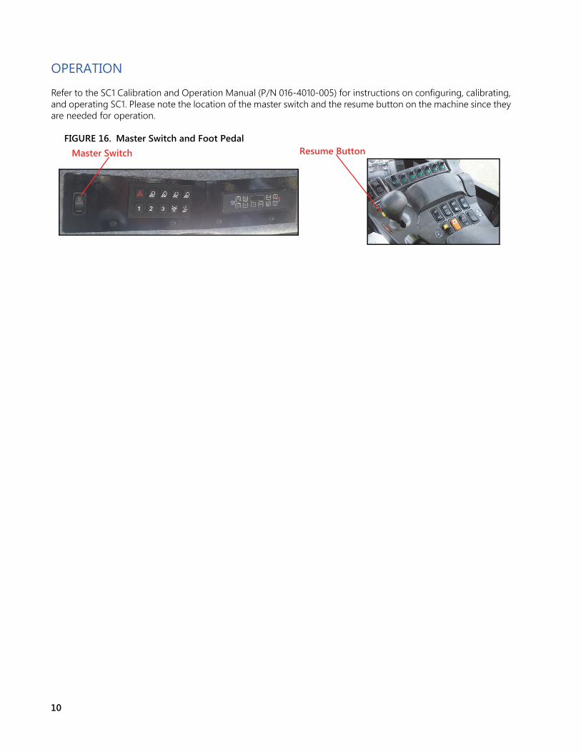
OPERATION
Refer to the SC1 Calibration and Operation Manual (P/N 016-4010-005) for instructions on configuring, calibrating, and operating SC1. Please note the location of the master switch and the resume button on the machine since they are needed for operation.
FIGURE 16. Master Switch and Foot Pedal Master Switch Resume Button
Manual No. 016-5033-052 Rev. B EC31812 08/18 11
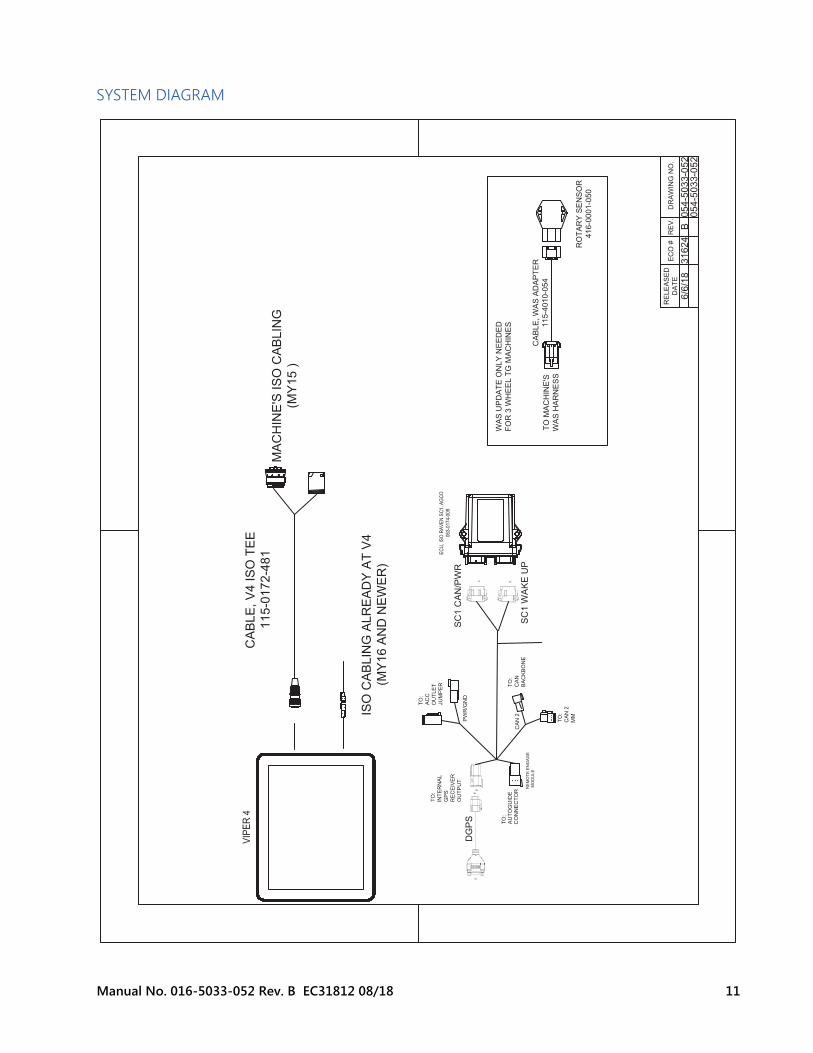
SYSTEM DIAGRAM
EC
O#
RE
LE
AS
ED
DA
TE
RE
V.
DR
AW
ING
NO
.
6/6
/18
31624
B054-5
033-0
52
054-5
033-0
52
J1
GRAY
J2
GREEN
J7
SC
1C
AN
/PW
R
SC
1W
AK
EU
P
DG
PS
VIP
ER
4
EC
U,IS
OR
AV
EN
SC
1,A
GC
O
06
3-0
17
4-0
09
CA
BLE
,V
4IS
OT
EE
11
5-0
17
2-4
81
MA
CH
INE
'SIS
OC
AB
LIN
G
(MY
15
)
ISO
CA
BLIN
GA
LR
EA
DY
AT
V4
(MY
16
AN
DN
EW
ER
)
TO
:
INT
ER
NA
L
GP
S
RE
CE
IVE
R
OU
TP
UT
CA
BLE
,W
AS
AD
AP
TE
R
115-4
010-0
54
TO
MA
CH
INE
'S
WA
SH
AR
NE
SS
RO
TA
RY
SE
NS
OR
416-0
001-0
50
WA
SU
PD
AT
EO
NLY
NE
ED
ED
FO
R3
WH
EE
LT
GM
AC
HIN
ES
J5
GR
AY
J6G
RA
Y
RE
MO
TE
EN
GA
GE
MO
DU
LE
TO
:A
UT
OG
UID
EC
ON
NE
CT
OR
PW
R/G
ND
CA
N2
TO
:
AC
C
OU
TLE
T
JU
MP
ER TO
:
CA
N
BA
CK
BO
NE
TO
:
CA
N2
MM

12