Embed Size (px)
Citation preview

S&C Power FusesTypes SM-4® andSM-5®
For use with SM Refill UnitsOutdoor Distribution (4.16 kV through 34.5 kV)
DESCRIPTIVE BULLETIN 242-30Page 1 of 18
October 16, 2000S&C ELECTRIC COMPANY
Supersedes Descriptive Bulletin 242-30 dated 7-12-93 ©2000

S & C E L E C T R I C C O M P A N Y
2
S&C Power Fuses—Type SM are especially suited forprotecting transformers, capacitor banks, and cables inoutdoor distribution substations on systems rated upthrough 34.5 kV. They offer the superior performancecharacteristics and reliability required to provide twofoldprotection—protection for the system upstream, and pro-tection for downstream equipment. Like other S&Cpower fuses, these fuses incorporate precision-engi-neered nondamageable silver or nickel-chrome fusibleelements. Consequently, the time-current characteristicsare precise and permanently accurate—assuring not onlyreliable and predictable performance, but also the contin-ued integrity of carefully engineered system coordinationplans. The precise time-current characteristics and non-damageability of these power fuses permit upstream pro-tective devices to be set for faster operation than may bepractical with other fuses or power circuit breakers. . .providing better system protection without compromis-ing coordination.
Type SM Power Fuses are offered withmaximum continuous current ratings of200, 300, 400, and 720 amperes . . . and areavailable with fault-interrupting ratingsfrom 28,000 amperes RMS asymmetrical at34.5 kV to 60,000 amperes RMS asymmet-rical at 4.16 kV. These power fuses areavailable in a variety of ampere ratings aswell, and in three different speeds: S&CStandard, Slow, and Coordinating. Thebroad selection of available ampere ratingsand speeds permits close fusing to achievemaximum protection and optimum coordi-nation.
Type SM Power Fuses may be operated (i.e., openedor closed when not carrying load) using a hookstick or auniversal pole equipped with a variety of fuse-handlingfittings. The SM-4 Power Fuse in the Disconnect VerticalStyle is available with an optional Loadbuster® attach-ment hook for full-load switching at full voltage. And,for convenience in fitting station layouts, Type SMPower Fuses are offered in three mounting configura-tions, as illustrated on pages 12 through 14.
Type SM Power Fuses are offered with a choice ofCypoxy® or porcelain station post insulators. Cypoxy isthe S&C trademark for S&C’s cycloaliphatic epoxy resinsystem. Cypoxy station post insulators are nontracking,self-scouring, nonweathering, and meet or exceed theelectrical and mechanical-strength requirements estab-lished in ANSI standard C29.9 (1983) for porcelain stan-dard-strength station post insulators.
Type SM Power Fuses Set the Standard forSystem and Equipment Protection
APPLICATION

3
The unique solid-material technique of fault interruptionwithin the refill unit of the Type SM Power Fuse pro-vides full-fault-spectrum protection. In protecting singletransformers, full-fault-spectrum protection means thatthe fuses will detect and interrupt all faults—large,medium, and small (even down to minimum melting cur-rent); whether the fault is on the primary or secondaryside; with line-to-line or line-to-ground voltage acrossthe fuse; whether the transformer is adjacent to the fuseor cable-connected to it from a remote location; andregardless of transformer winding connections. SMPower Fuses are capable of handling the full range oftransient recovery voltages associated with these condi-tions. And they develop a positive internal gap of highdielectric strength after circuit interruption, thus preclud-ing destructive reignitions when exposed to full systemvoltage—such as are experienced with current-limitingfuses after clearing under low recovery-voltage condi-tions.
The close fusing necessary to provide superior pro-tection for secondary-side faults is possible with SMPower Fuses because: they utilize silver or pretensionednickel-chrome fusible elements that are not damaged bytransient surges that may heat the element nearly to thesevering point; they are available in a variety of speedsthat provide time-current characteristics especiallysuited to protecting transformers for very low-magnitudefault currents; and because they possess substantial over-load capabilities and surge capacity more than adequateto withstand transformer magnetizing-inrush currents aswell as severe hot- and cold-load pickup currents. Closefusing with SM Power Fuses, coupled with the excep-tional low-current fault-interrupting performance,assures maximum protection for the transformer for abroad range of secondary-side fault currents, thus mini-mizing the life-shortening thermal and mechanicalstresses associated with prolonged transformer through-faults.
Superior to Current-Limiting FusesType SM Power Fuses have helically coiled silverfusible elements that are of solderless construction andare surrounded by air. Because of this construction, thefusible element is free from mechanical and thermalstress and confining support, and therefore is not subjectto damage—even by inrush currents that approach but donot exceed the fuse’s minimum melting time-currentcharacteristic curve. Current-limiting fuses, in contrast,
have fusible elements which consist of a number of veryfine diameter wires, or one or more perforated ornotched ribbons, surrounded by, and in contact with, afiller material such as silica sand. Because of this con-struction, current-limiting fuses are susceptible to ele-ment damage caused by current surges that approach thefuse’s minimum melting time-current characteristiccurve. This damage may occur in one or more of the fol-lowing ways:
� The fusible element may melt, but not completely sep-arate because the molten metal is constrained by thefiller material—resulting, possibly, in resolidificationof the element with a different cross-sectional area.
� One or more, but not all, of the parallel wires or rib-bons of the fusible element may melt and separate.
� The fusible element may break as a result of fatiguebrought about by current-cycling that can cause local-ized buckling from thermal expansion and contrac-tion.
Damage to fusible elements of current-limiting fuses,as described above, may shift or alter their time-currentcharacteristics, resulting in a loss of complete coordina-tion between the fuse and other downstream overcurrentprotective devices. Moreover, a damage current-limitingfuse element may melt due to an otherwise harmlessinrush current, but the fuse may fail to clear the circuitdue to insufficient power flow—with the fuse continuingto arc and burn internally due to load-current flow.
Because of the potential for damage to the fusible ele-ment from inrush currents, and because of the effects ofloading and manufacturing tolerances, current-limitingfuse manufacturers typically require that, when applyingsuch fuses, adjustments be made to the minimum melt-ing time-current characteristic curves. These adjustmentsare referred to as “safety zones” or “setbackallowances,” and range from 25% in terms of time to25% in terms of current. The latter can result in anadjustment of 250% or more in terms of time, dependingon the slope of the time-current characteristic curve atthe point where the safety zone or setback allowance ismeasured.
Furthermore, most current-limiting fuses inherentlyhave steep, relatively straight time-current characteristiccurves which, together with the required large safety-zone or setback-allowance adjustments, force the selec-tion of a current-limiting fuse ampere rating substan-
Transformer Protection with Type SM Power Fuses
S & C E L E C T R I C C O M P A N Y

4
S & C E L E C T R I C C O M P A N Y
tially greater than the transformer full-load current inorder to withstand combined transformer-magnetizingand load inrush currents, and also to coordinate with sec-ondary-side protective devices. The selection of suchlarge fuse ampere ratings results in reduced protectionfor the transformer and possible impairment of coordina-tion with upstream protective devices. Also, since high-ampere-rated current-limiting fuses typically require theuse of two or three lower-ampere-rated fuses connectedin parallel, increased cost and space requirements may beencountered.
Because S&C’s solid-material power fuses incorpo-rate fusible elements that are nondamageable, there’s noneed for “safety zones” or “setback allowances” . . .allowing closer fusing than is possible with other fuses.They are thus better able to protect the transformeragainst damage due to faults between the transformer andthe secondary-side protective device, and furthermore, tosupply backup protection in the event of incorrect func-tioning of the secondary-side protective device. In addi-tion, the ability to fuse closer to the transformer full-loadcurrent facilitates coordination with upstream protectivedevices by allowing them to have lower ampere ratingsand/or settings for faster response.
Another plus for Type SM Power Fuses derives fromthe fact that they are not “voltage critical,” and thereforemay be applied at any system voltage equal to or lessthan the rated voltage of the fuse. Current-limiting fuses,in contrast, can be applied only at system voltagesbetween 70% and 100% of the nameplate rating.Moreover, current-limiting fuses will often producesevere voltage surges during circuit interruption that cancause spurious operation—or even destruction—of surgearresters or failure of transformer insulation.
Cable Protection with Type SM Power FusesAn important consideration in planning underground dis-tribution systems is the protection of insulated cables.The primary concern in establishing such protection is toprevent the conductor temperature rise under short-cir-cuit conditions from exceeding the maximum allowabletemperature limits specified for the conductor insulation.This type of protection can be achieved by careful selec-tion of the conductor size and material, as well as bycareful selection of the types and characteristics of theupstream protective devices. There is no need forupstream protective devices to provide overload protec-tion for medium-voltage cables, since the cable sizes aretypically selected to carry the maximum anticipated levelof overload current on a continuous basis.
S&C Type SM Power Fuses located on riser poles orat cable-feeder terminations in distribution substationsprovide excellent protection for insulated cables becausethey are extremely fast operating, and because they areoffered in a wide selection of ampere ratings and perma-nently accurate and precise time-current characteristics. . . with these attendant benefits:
� The conductor temperature rise following a fault isminimized due to the fast operation of the fuse, per-mitting the use of conductors one or more sizessmaller than those required by slower operating circuitbreakers—resulting in considerable savings; and
� The upstream protective device can be set to operatefaster while still coordinating with the Type SM PowerFuse. Also, Type SM Power Fuses provide selectiveisolation of only faulted phases of three-phase feedersserving single-phase loads, unlike the undiscriminat-ing operation of circuit breakers which remove allthree phases from the system—even on single-phasefaults.
Circuit breakers (and their associated relays) are com-monly used where the reclosing capability of the circuitbreaker is an advantage, such as applications involving

S & C E L E C T R I C C O M P A N Y
5
overhead lines which have a relatively high incidence oftransient or temporary faults. This reclosing feature isneither useful nor desirable, however, on undergroundcable distribution systems where the conductors aredirect buried or enclosed in conduit. The incidence offaults on these systems is low, and the rare faults that dooccur are not transient and result in significant damagethat would only be compounded by an automatic reclos-ing operation.
Capacitor Bank Protection with Type SM Power FusesIn addition to transformer and cable protection, Type SMPower Fuses are suitable for group fusing of stationcapacitor banks, particularly where available fault cur-rents are high. These power fuses have a substantial con-tinuous peak-load capability which permits the use ofsmaller ampere ratings than would be possible with dis-tribution fuse links, other makes of power fuses, or cur-rent-limiting fuses—and without risking nuisance fuseoperations (“sneakouts”) due to capacitor bank inrush or
outrush currents. This close fusing with SM Power Fusesensures rapid isolation of faulted capacitor banks, pro-tecting the system from unnecessary outages.
Other Application ConsiderationsThe discharge of Type SM Power Fuses is nonconduct-ing—unlike the highly ionized blast of expulsion-typefuses that use fiber-lined fuse tubes. Consequently, it ispossible to make use of standard electrical clearances toground and between adjacent phases . . . a definite plusfor many station applications where space may be at apremium. (For recommended mounting clearances, referto the appropriate S&C Data Bulletin.) Moreover,because of the selection of mounting configurations,diverse station layouts can be accommodated using SMPower Fuses.
For additional detailed application recommendationsand technical information, including minimum meltingand total clearing time-current characteristics, preloadingand ambient temperature adjustment factors, and loadingcapabilities, consult your nearest S&C fusing specialist.

The Fusible ElementS&C Type SM Power Fuses possess the performancecharacteristics and quality that make them especiallysuitable for fault protection on 4.16-kV through 34.5-kVdistribution systems. The fuses are available in a widevariety of ampere ratings and time-current characteris-tics, permitting close fusing to achieve maximum protec-tion and optimum coordination. The initial and sustainedaccuracy of their melting time-current characteristicsassures that these fuses can be depended upon to operateexactly when they should and—equally important—notto operate when they shouldn’t. This permanent accuracyis achieved principally in the design and construction ofthe fusible element.
Nondamageable ConstructionS&C Power Fuses have silver or pretensioned nickel-chrome elements with these characteristics: (1) they are
drawn through precision dies to very accurate diameters,and (2) they are of solderless construction, brazed intotheir terminals. Their melting time-current characteristicsare precise, with only 10% total tolerance in melting cur-rent, compared to the 20% tolerance of many fuses (20%and 40% respectively, in terms of time). And their designand construction features assure that they will conform totheir time-current characteristics not only initially, but ona sustained basis . . . neither age, corrosion, or vibration,nor surges that heat the element nearly to the severingpoint, will affect the characteristics of S&C Power Fuses.
6
S & C E L E C T R I C C O M P A N Y
CONSTRUCTION AND OPERATION
Series of leversreduces springforce to correctamount for preten-sioning of fusibleelement
Lower terminal
Arcing rod
Fusible element ofnickel-chrome wire,pretensioned
Nondamageable low-current, nickel-chrome fusible ele-ment for SM Refill Units rated 1, 2, and 3E amperes. Inthese ratings, the nickel-chrome wire is too fine to with-stand the full force of the spring. An assembly of levers ineffect multiplies the tensile strength of the wire to permitthe desired pretensioning without jeopardizing the securityof the fusible element.

7
The construction features illustrated below make S&Cfusible elements nondamageable with these advantages:
1. Superior transformer protection. SM Power Fusesmake it possible to fuse close to the transformer full-load current, thus providing protection against abroad range of secondary-side faults.
2. Higher levels of service continuity. “Sneakouts”(unnecessary fuse operations) are eliminated.
3. Close coordination with other overcurrent protectivedevices . . . attainable because of the initial and sus-tained precision of the fusible elements, and becauseno “safety zones” or “setback allowances” need beapplied to the published time-current characteristicsto protect the element against damage.
4. Operating economies. There is no need to replaceunblown companion fuses on suspicion of damagefollowing a fuse operation.
Nondamageable nickel-chrome fusible element for SMRefill Units rated 5E and 7E amperes. When called upon tooperate, the pretensioned nickel-chrome wire weakensabruptly and separates before its cross-section changes.
Nondamageable silver fusible element for SM Refill Unitsrated 10E amperes and larger. These ratings employ the sil-ver-fusible-element, strain-wire construction, which is notdamaged by overloads or transient faults approaching theminimum melting current.
Fusible element ofsilver wire, helicallycoiled to absorbmechanical vibra-tion and thermalshock
Lower terminal
Arcing rod
Fusible element ofnickel-chrome wire,pretensionedSilver-brazed joints
Arcing rod
Strain wireSilver-brazedjoints
Lower terminal
S & C E L E C T R I C C O M P A N Y

8
S & C E L E C T R I C C O M P A N Y
The Refill UnitThe refill unit consists of a fusible element, arcing rods,and a solid-material arc-extinguishing medium containedwithin a filament-wound glass-epoxy tube.
The fusible element is connected at one end—througha current-transfer bridge—to the refill unit lower ferrule.At the other end, the fusible element is connected to themain arcing rod, which extends upward through the mainbore of the refill unit to the upper terminal.
The auxiliary arcing rod, of stainless steel, is threadedinto the upper terminal and extends downward through asmall-diameter stepped bore and through an opening inthe current-transfer bridge. No load current is carried bythis auxiliary rod since, at its small-diameter section, it isinsulated from the auxiliary arcing contact.
Upper terminal—for attachmentof spring-and-cable assembly
Fuse-tube plug—cemented toglass-epoxy tube
Outer tube—filament-woundglass-epoxy
Solid-material arc-extinguish-ing medium
Auxiliary arcing rod—stainlesssteel
Main arcing rod—silver-cladcopper; under moderate-to-highfault conditions arc is drawnthrough main bore
Stepped portion of auxiliarybore—large diameter delaysarc extinction until sufficient gapis attained to prevent reignitionin the main bore
Reduced section of auxiliaryarcing rod is insulated to pre-vent parallel load-current path
Auxiliary arcing contact—under low-fault conditions thearc is transferred to this pointand drawn into the auxiliarybore
Fusible element
Lower ferrule—magneformedonto glass-epoxy tube
Current-transfer bridge

9
Spring-and-cable assembly—stainless-steel spring provides high-speed elongationof arc within refill unit when fuse operates.Copper cable inside spring carries load (andfault) current
Refill Unit and Holder Assembly
SM Refill Unit—replaced aftera fault-clearing operation
Hexagonal clamping nut—locks refill unit in place
Pull-ring
Porcelain jacket
Silver-surfaced ferrule
Silver-surfaced ferrule
Lifting eye
Rain shield
SM-4 Holder1
1 SM-5 Holders are similar.
S & C E L E C T R I C C O M P A N Y

10
S & C E L E C T R I C C O M P A N Y
Fault Interruption in SM Refill UnitsFast, positive fault interruption is achieved in the SMPower Fuse refill unit—after the fusible element melts—by the high-speed elongation of the arc within one of thetwo bores, and by the efficient deionizing action of thegases liberated from the solid-material arc-extinguishingmedium. Elongation of the arc is accomplished by theaction of the spring-and-cable assembly housed withinthe holder. The illustrations which follow show how thearc is channeled into the bore better suited for interrup-tion of the particular magnitude of fault.
The main bore is sized to accommodate the arc (andgas generation) associated with faults ranging from1,000 to 60,000 amperes. For faults of 1,000 amperes orless, the small-diameter auxiliary bore provides intimatecontact between the arc and the arc-extinguishingmedium, to ensure positive arc extinction.
Regardless of fault level, the high rate of dielectricrecovery more than matches the transient-recovery-volt-age severity of any circuit where the SM is applied.
Low-FaultInterruption
Moderate-to-High-Fault Interruption
1 2
3a
3b

11
Low-Fault Interruption(Up to 1,000 Amperes)Overcurrent melts the silver fusible element, thentransfers to the strain wire, which volatilizesinstantly. Arcing is initiated as illustrated.
Both the main arcing rod and the auxiliary arcingrod are drawn upward by the spring-and-cableassembly in the fuse holder. After approximately¹⁄₈-inch travel, the lower (uninsulated) section of theauxiliary arcing rod engages the auxiliary contact,momentarily shorting out the arc.
Arcing is reinitiated in the small-diameter auxiliarybore when the tip of the auxiliary arcing rod travelsabout one inch (at which time the tip clears the aux-iliary contact).
The large-diameter section of the auxiliary boredelays arc extinction until a sufficient gap isattained to preclude reignition in the main bore.Moreover, the tip of the main arcing rod leads thetip of the auxiliary arcing rod by approximately oneinch—further ensuring that the arc will not transferback to the main bore.
After the auxiliary arcing rod has traveled aboutone-half stroke, sufficient deionization has occurredto extinguish the arc.
Moderate-to-High-Fault InterruptionOvercurrent melts the silver fusible element, thentransfers to the strain wire, which volatilizesinstantly. Arcing is initiated as illustrated.
Both the main arcing rod and the auxiliary arcingrod are drawn upward by the spring-and-cableassembly in the fuse holder. After approximately¹⁄₈-inch travel, the lower (uninsulated) section of theauxiliary arcing rod engages the auxiliary contact,momentarily shorting out the arc.
The auxiliary arcing rod—momentarily providingthe only current path for the moderate-to-high mag-nitude fault current—quickly melts at the reducedsection and separates from the one-inch arcing tip.Any arcing initiated in the auxiliary bore cannot per-sist because of the high-resistance (stainless-steel)path and quickly transfers to the lower-resistancemain arcing rod in the main bore.
The arc is lengthened as the main rod is drawnupward into the main bore. The large circumferenceof the main bore provides greater surface exposureof the arc-extinguishing medium to the heatingeffects of the arc, thereby enhancing the generationof arc-quenching deionizing gases.
After the main arcing rod has traveled about one-half stroke, sufficient deionization has occurred toextinguish the arc.
1
2
3a
4a
5a
1
2
3b
4b
5b
4a
4b
5a
5b
4b
4a 5a
5b
S & C E L E C T R I C C O M P A N Y

12
FUSE MOUNTINGS
S & C E L E C T R I C C O M P A N Y
SM-4 and SM-5 Power Fuses, Vertical Style
Disconnect (180° Opening) Vertical Style12(14.4-kV model illustrated, with Cypoxy3 station post insulators)
1 SM-4 Power Fuse shown; SM-5 Power Fuse is similar.
2 Complete mounting shown; live parts can be furnished separately.
3 Cypoxy is the S&C trademark for S&C’s cycloaliphatic epoxy resin sys-tem. Cypoxy is nontracking, self-scouring, nonweathering . . . there’s nevera compromise of insulation integrity.
Galvanizedformed-steelchannel base—³⁄₁₆-inch thick—hasmultiple mountingholes and slots tofacilitate installa-tion
Insulators . . . offered with achoice of S&C Cypoxy orporcelain station post insulators
Bronze two-hole terminalpad accepts a wide variety ofconnectors. (Parallel-mountedfuse employs aluminum terminalpads)
Fuse-holder latch—stainlesssteel with galvanized steel stop,provides positive, secure engage-ment of holder
Upper and lower mountingcontacts are copper, heavilysilver clad. Contacts are bifur-cated to provide four-point con-tact at each ferrule and arebacked up by a ¹⁄₄-inch thick gal-vanized steel yoke and stainless-steel loading springs to ensureminimum electrical resistance atcurrent-transfer points
Rain shield—gravity oper-ated—minimizes entry of waterwhen the holder is left hangingopen (which is not recom-mended for more than shortperiods of time)
Cast bronze hinge features broad guiding surfaces on innerfaces to provide positive self-guiding action for holder duringopening and closing; also features two-hole terminal pad whichaccepts a wide variety of connectors

Bronze pull-ring—large,easily accessible. . . pivots topry up latch
13
Parallel-MountedSM-5 Power Fuse2 (14.4-kV model illustrated)
AVAILABLE MOUNTING STYLES AND RATINGS
Style Fuse Type
Ratings
kV Amperes, RMS
Nom. Max BIL MaxInterrupting1111
(Sym.)
Disconnect180° Opening
Vertical
SM-4
7.214.42534.5
8.317.02738
95110150200
200E200E200E200E
15 60012 5009 4006 250
SM-5
7.27.2
14.414.42534.5
8.38.3
17.017.02738
9595
110110150200
400E720E�
400E720E�
300E300E
26 00026 00034 00025 00020 00017 500
1 Refer to tables on pages 17 and 18 for additional, detailedinformation on interrupting ratings.
� Parallel fuses.
Silver surfaced upperferrule
Porcelain jacket overglass-epoxy sleeve Holder—removable
assembly containingthe SM-4 or SM-5Refill Unit
Silver surfaced lowerferrule
S & C E L E C T R I C C O M P A N Y

14
S & C E L E C T R I C C O M P A N Y
Disconnect (90° Opening) Inverted Style1(14.4-kV model illustrated)
1 Complete mounting shown; live parts can be furnished separately.
2 Cypoxy is the S&C trademark for S&C’s cycloaliphatic epoxy resin sys-tem. Cypoxy is nontracking, self-scouring, nonweathering . . . there’s nevera compromise of insulation integrity.
SM-5 Power Fuses, Inverted Style
1 Refer to table on page 18 for additional, detailed information on inter-rupting ratings.
AVAILABLE MOUNTING STYLES AND RATINGS
Style Fuse Type
Ratings
kV Amperes, RMS
Nom. Max BIL MaxInterrupting1111
(Sym.)
Disconnect90° Opening
InvertedSM-5
7.214.42534.5
8.317.02738
95110150200
400E400E300E300E
26 00034 00020 00017 500
Holder—removableassembly containing theSM-5 Refill Unit.
Silver surfacedferrule
Galvanized formed-steel channelbase—³⁄₁₆-inch thick—has multiple mountingholes and slots to facilitate installation
Insulators . . . offeredwith a choice of S&CCypoxy2 or porcelainstation post insulators
Bronze two-holeterminal padaccepts a widevariety of connec-tors
Hinge- and latch-endmounting contacts arecopper, heavily silver clad.Contacts are bifurcated toprovide four-point contact ateach ferrule, and are backedup by a ¹⁄₄-inch thick galva-nized steel yoke and stain-less-steel loading springs, toensure minimum electricalresistance at current-transferpoints
Porcelain jacket overglass-epoxy sleeve
Rain shield—effectively covers exhaust end of holderto prevent entry of water
Cast bronze hingeprovides positive self-guiding action for holderduring opening and clos-ing; also features two-hole terminal pad whichaccepts a wide variety ofconnectors
Bronze pull-ring—large, easily accessible. . . pivots to disengagelatch mechanism
Bronze lifting eye—for installing or remov-ing holder
Silver surfacedferrule

15S & C E L E C T R I C C O M P A N Y
FUSE HANDLING
SM Power Fuses in the Disconnect 180° OpeningVertical and Disconnect 90° Opening Inverted Styleshave been designed such that opening and closing oper-ations can be performed using any station-class switchstick or a universal pole equipped with an appropriateS&C Handling Tool. Moreover, holders for disconnectstyle power fuses are equipped with a pull-ring and/orlifting eye to facilitate hot-stick handling for removaland replacement of the holder. These power fuses are notdesigned for live-switching duty (except in the specialcase detailed on the following page) and must not beopened under load. For a complete description of S&CHandling Tools for use with Type SM Power Fuses, referto S&C Descriptive Bulletin 851-30.
Note: Installation or removal of holders for TypeSM-4 Power Fuses rated 34.5 kV, and also for TypeSM-5 Power Fuses rated 25 kV and 34.5 kV, should beperformed by hand due to the substantial weight of theholders—but only after the fuse has been de-energizedand properly grounded in accordance with local operat-ing procedures.
Handling the Fuse Holder in Disconnect 180° Opening Vertical Style SM-4 Mountings Rated 25 kV andBelow
Opening the fuse. The operator uses astation prong to swing the SM fuseholder to the fully open position.
Removing the fuse. The operatorinserts the station prong into thelifting eye of the fuse holder, easesthe trunnions up and out of thehinge, and lowers the fuse holderto the ground.
S & C E L E C T R I C C O M P A N Y

16
S & C E L E C T R I C C O M P A N Y
Load Switching with Loadbuster®
Type SM-4 Power Fuses (Disconnect 180° OpeningVertical Style) may be operated with Loadbuster, S&C’sportable loadbreak tool, provided the mounting isequipped with an optional attachment hook. Loadbustermakes possible full-load switching at full voltage, aswell as switching of associated magnetizing and line-charging currents. No disconnects (isolators) or inter-rupter switches need to be installed in series with thefuse. Loadbuster switching of the SM-4 is illustrated atthe right.
Elimination of series disconnects and elimination ofthe need for an interrupting unit or mechanism at eachfuse result in greatly improved appearance and immedi-ate cost savings. Because the interrupting unit is in theLoadbuster tool—and only one Loadbuster is needed foreach appropriate truck—the advantages of low-cost, uni-versal load switching are available anywhere on the dis-tribution system. S&C Descriptive Bulletin 811-30 fullydescribes the Loadbuster concept.
ATTACH: Reach across the front of the SM-4 PowerFuse and attach Loadbuster’s anchor to the attach-ment hook on the fuse upper live parts; then, engageLoadbuster’s pull-ring hook with the fuse-holder pull-ring.
PULL: A firm, steady downward pull on Loadbuster—to its maximum extended length—opens the fuse inthe normal manner, as the current is diverted throughLoadbuster. At a predetermined point in the openingstroke, Loadbuster trips, breaking the circuit positively.
ROLL OFF: Loadbuster is disengaged by first remov-ing its anchor from the SM-4 attachment hook, whilemaintaining the engagement of the pull-ring of theholder and the Loadbuster pull-ring latch. Loadbusteris then used to guide the fuse holder to the fully openposition—after which Loadbuster is removed from thepull-ring with a simple “roll-off” motion.
Loadbuster operation of Type SM-4 Power Fuse (Disconnect 180° Opening Vertical Style) equipped withoptional Loadbuster attachment hook.
1
2
3
1
2
3
17
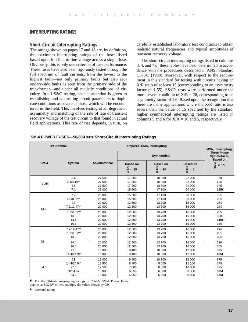
Short-Circuit Interrupting RatingsThe ratings shown on pages 17 and 18 are, by definition,the maximum interrupting ratings of the fuses listedbased upon full line-to-line voltage across a single fuse.Obviously, this is only one criterion of fuse performance.These fuses have also been rigorously tested through thefull spectrum of fault currents, from the lowest to thehighest fault—not only primary faults but also sec-ondary-side faults as seen from the primary side of thetransformer—and under all realistic conditions of cir-cuitry. In all S&C testing, special attention is given toestablishing and controlling circuit parameters to dupli-cate conditions as severe as those which will be encoun-tered in the field. This involves testing at all degrees ofasymmetry and matching of the rate of rise of transientrecovery voltage of the test circuit to that found in actualfield applications. This rate of rise depends, in turn, on
carefully established laboratory test conditions to obtainrealistic natural frequencies and typical amplitudes oftransient recovery voltage.
The short-circuit interrupting ratings listed in columns3, 4, and 7 of these tables have been determined in accor-dance with the procedures described in ANSI StandardC37.41 (1988). Moreover, with respect to the require-ment in this standard for testing with circuits having anX/R ratio of at least 15 (corresponding to an asymmetryfactor of 1.55), S&C’s tests were performed under themore severe condition of X/R = 20, corresponding to anasymmetry factor of 1.6. Based upon the recognition thatthere are many applications where the X/R ratio is lesssevere than the value of 15 specified by the standard,higher symmetrical interrupting ratings are listed incolumns 5 and 6 for X/R = 10 and 5, respectively.
SM-4 POWER FUSES—50/60-Hertz Short-Circuit Interrupting Ratings
kV, Nominal Amperes, RMS, InterruptingMVA, Interrupting,
Three-PhaseSymmetrical,
Based onSM-4 System Asymmetrical
Symmetrical
Based on Based on Based on
7.2�
2.42.4/4.16Y
4.87.2
27 50027 50027 50025 000
17 20017 20017 20015 600
18 80018 80018 80017 100
22 00022 00022 00020 000
70125145195�
14.4
7.24.8/8.32Y
127.2/12.47Y
25 00025 00020 00020 000
15 60015 60012 50012 500
17 10017 10013 70013 700
20 00020 00016 00016 000
195225260270
7.62/13.2Y13.814.416.5
20 00020 00020 00020 000
12 50012 50012 50012 500
13 70013 70013 70013 700
16 00016 00016 00016 000
285300310�
355
25
7.2/12.47Y7.62/13.2Y
13.8
20 00020 00020 000
12 50012 50012 500
13 70013 70013 700
16 00016 00016 000
270285300
14.416.523
14.4/24.9Y
20 00020 00015 00015 000
12 50012 5009 4009 400
13 70013 70010 30010 300
16 00016 00012 00012 000
310355375405�
34.5
2314.4/24.9Y
27.620/34.5Y
34.5
15 00013 90012 50010 00010 000
9 4008 7007 8006 2506 250
10 3009 5008 5006 8006 800
12 00011 10010 0008 0008 000
375375375375�
375�
XR---- 15=
XR---- 15=
XR---- 10=
XR---- 5=
� For the 50-hertz interrupting ratings of 7.2-kV SM-4 Power Fusesapplied at 8.32 kV or less, multiply the values shown by 0.9.
� Nominal rating
INTERRUPTING RATINGS
S & C E L E C T R I C C O M P A N Y

18
SM-5 POWER FUSES—50/60-Hertz Short-Circuit Interrupting Ratings
kV, Nominal Amperes, RMS, Interrupting1MVA, Interrupting,
Three-PhaseSymmetrical,1
Based onSM-5 System Asymmetrical
Symmetrical
Based on Based on Based on
4.16�2.4
2.4/4.16Y60 00060 000
37 50037 500
41 00041 000
48 00048 000
155270�
7.2
2.42.4/4.16Y
4.87.2
44 50044 50043 50041 500
28 00028 00027 00026 000
30 50030 50029 80028 500
35 60035 60034 80033 200
115200225325�
14.4(50/60-Hz ratings)
7.24.8/8.32Y
127.2/12.47Y
40 00040 00040 00040 000
25 00025 00025 00025 000
27 40027 40027 40027 400
32 00032 00032 00032 000
310360520540
7.62/13.2Y13.814.416.5
40 00040 00040 00040 000
25 00025 00025 00025 000
27 40027 40027 40027 400
32 00032 00032 00032 000
570600620�
715
14.4(60-Hz ratings)
7.24.8/8.32Y
127.2/12.47Y
55 00055 00055 00055 000
34 60034 60034 60034 600
34 60034 60034 60034 600
34 60034 60034 60034 600
430500720750
7.62/13.2Y13.814.4
54 00054 00054 000
34 00034 00034 000
34 00034 00034 000
34 00034 00034 000
780815850�
25
7.2/12.47Y7.62/13.2Y
13.814.4
32 00032 00032 00032 000
20 00020 00020 00020 000
21 90021 90021 90021 900
25 60025 60025 60025 600
430455480500
16.523
14.4/24.9Y
32 00032 00032 000
20 00020 00020 000
21 90021 90021 900
25 60025 60025 600
570795860�
34.5
2314.4/24.9Y
27.620/34.5Y
34.5
28 00028 00028 00028 00028 000
17 50017 50017 50017 50017 500
19 20019 20019 20019 20019 200
22 40022 40022 40022 40022 400
695755835
1000�
1000�
XR---- 15=
XR---- 15=
XR---- 10=
XR---- 5=
1 These ratings apply provided that mounting, holder, and refill unit arematched (identified by large arrow on nameplate or label). For interruptingratings applying to previous designs, see S&C Data Bulletin 201-190,page 4.
� Applies to 4.16-kV refill unit in 7.2-kV holder when applied in 7.2-kV
mounting, for systems rated 2.4 or 2.4/4.16Y kV. Note: For 7.2-kV coordi-nating speed refill unit in a 7.2-kV holder when applied in a 7.2-kV mount-ing, for systems rated 2.4 or 2.4/4.16Y kV, refer to ratings listed for 7.2-kVSM-5 Power Fuse
� Nominal rating.
S & C E L E C T R I C C O M P A N Y

Headquarters: 6601 N. Ridge Blvd., Chicago, IL 60626-3997 • Telephone: (773) 338-1000 • Fax: (773) 338-3657 • www.sandc.com
Offices Worldwide