Embed Size (px)
Citation preview

Rev. 1-0310
1
Table of Contents Introduction 2 SC-5 Electronic Stencil Machine Set Up 3 Computer Specifications 4 Stencil-CAD Software Installation 5 Cable/Port Setup & Cutting Preparation 9 Stencil-CAD Menu Icon Definitions 14 Cutting Your First Stencil 15 Stencil-CAD “Stencil” Font Previews 20 “Diagraph Symbol” Font Character Map 21 Frequently Asked Questions 22 LED Error Codes 24 Warranty Information 25 Notes 26

2
Introduction Thank you for purchasing the SC-5 Electronic Stencil Machine and/or Stencil-CAD software. Our systems and software are designed to simplify your job of creating, saving and cutting a wide variety of stencils and signs. The SC-5 Electronic Stencil Machine is made in the U.S.A. and is backed by a one year limited parts and labor warranty. The enclosed quick start instructions should give you all the help necessary to be able to have your machine and software up and running in no time.
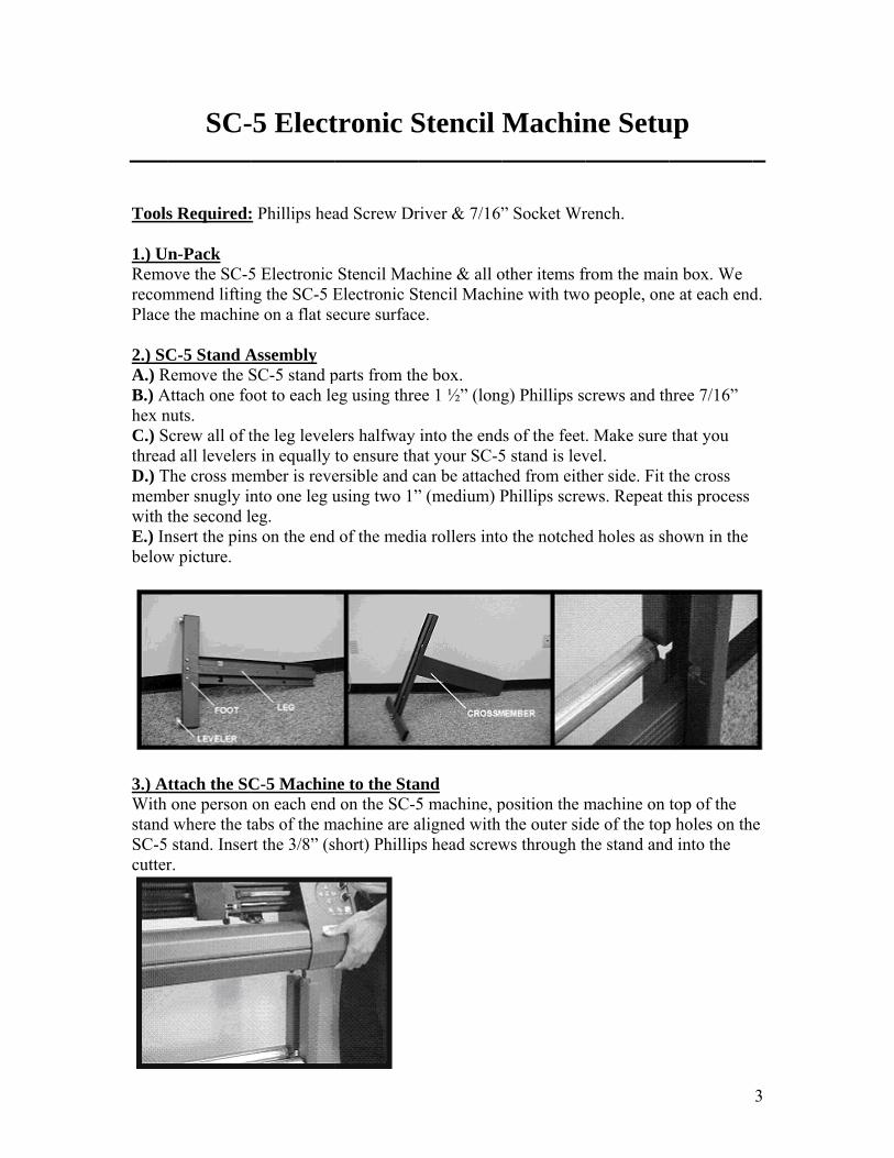
CAUTION: The SC-5 Stencil Machine is heavy and could cause injury if handled improperly. Two people are recommended to safely unpack & set up the SC-5 Electronic Stencil Machine.
Tools 1.) URemorecomPlace 2.) SCA.) RB.) Ahex nC.) SthreaD.) Tmembwith E.) Inbelow
3.) AWith standSC-5cutter
SC-
s Required:
Un-Pack ove the SC-5mmend liftine the machin
C-5 Stand ARemove the SAttach one fonuts. Screw all of td all levelers
The cross meber snugly inthe second lnsert the pinw picture.
Attach the SCone person
d where the t stand. Inserr.
-5 Elect
: Phillips hea
5 Electronic ng the SC-5 Ene on a flat se
Assembly SC-5 stand poot to each le
the leg levels in equally
ember is revento one leg ueg. s on the end
C-5 Machinon each end
tabs of the mrt the 3/8” (s
tronic S
ad Screw Dr
Stencil MacElectronic Secure surfac
parts from theg using thre
ers halfway to ensure thaersible and cusing two 1”
d of the medi
ne to the Stad on the SC-5machine are ashort) Phillip
Stencil
river & 7/16”
chine & all otencil Mache.
he box. ee 1 ½” (long
into the endat your SC-5
can be attach” (medium) P
ia rollers into
and 5 machine, paligned with ps head screw
Machin
” Socket Wr
other items frhine with two
g) Phillips sc
ds of the feet5 stand is levhed from eithPhillips scre
o the notche
position the mthe outer sid
ws through t
ne Setu
rench.
from the maio people, one
crews and th
. Make sure vel. her side. Fit tws. Repeat t
d holes as sh
machine on de of the tophe stand and
up
in box. We e at each end
hree 7/16”
that you
the cross this process
hown in the
top of the p holes on thd into the
3
d.
e
4
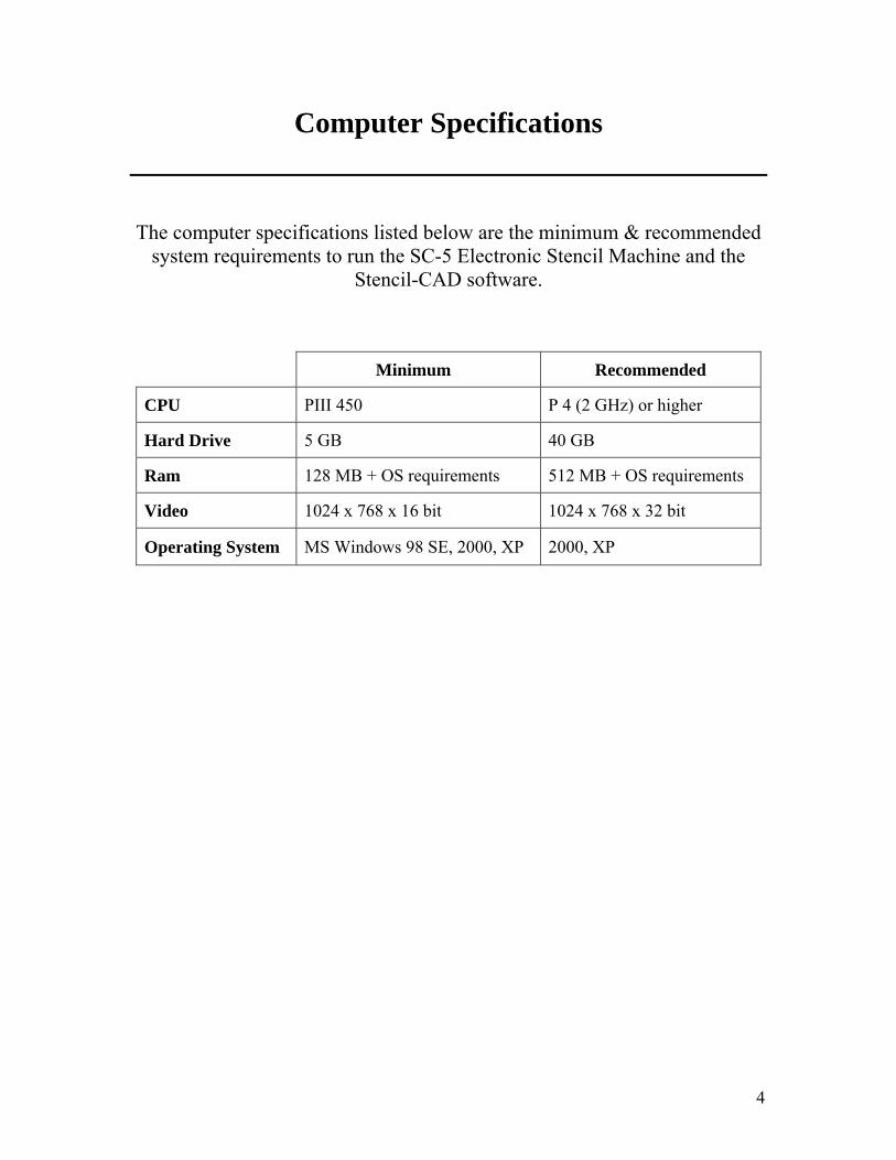
Computer Specifications
The computer specifications listed below are the minimum & recommended system requirements to run the SC-5 Electronic Stencil Machine and the
Stencil-CAD software.
Minimum Recommended
CPU PIII 450 P 4 (2 GHz) or higher
Hard Drive 5 GB 40 GB
Ram 128 MB + OS requirements 512 MB + OS requirements
Video 1024 x 768 x 16 bit 1024 x 768 x 32 bit
Operating System MS Windows 98 SE, 2000, XP 2000, XP
NOT 1.) PThe s 2.) Tappro
3.) Oproce 4.) AClick
St
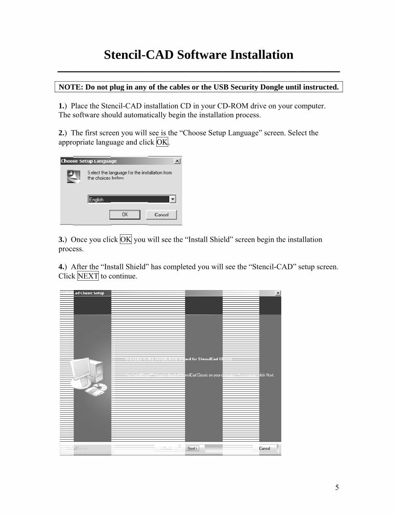
TE: Do not p
Place the Stensoftware sho
The first screopriate langu
Once you clicess.
After the “Insk NEXT to c
tencil-C
plug in any
ncil-CAD inould automat
een you will uage and clic
ck OK you w
stall Shield”continue.
CAD So
of the cable
nstallation CDtically begin
see is the “Cck OK.
will see the “
” has comple
oftware
es or the US
D in your CD the installat
Choose Setup
“Install Shie
eted you will
e Instal
SB Security
D-ROM drivtion process.
p Language”
eld” screen b
l see the “Ste
llation
Dongle unti
ve on your c.
” screen. Sel
begin the inst
encil-CAD”
il instructed
computer.
lect the
tallation
setup screen
5
d.
n.
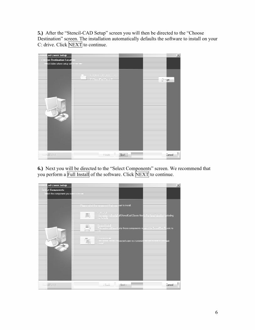
5.) ADestiC: dr
6.) Nyou p
After the “Steination” screrive. Click N
Next you wilperform a Fu
encil-CAD Seen. The inst
NEXT to con
l be directedull Install of
Setup” screetallation autontinue.
d to the “Selethe software
en you will thomatically de
ect Compone. Click NEX
hen be directefaults the s
ents” screenXT to contin
ted to the “Coftware to in
n. We recommnue.
Choose nstall on you
mend that
6
ur
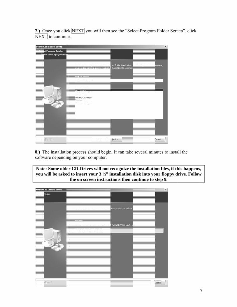
7.) ONEX
8.) Tsoftw Noteyou w
Once you clicXT to continu
The installatiware dependi
e: Some oldewill be aske
ck NEXT youe.
ion process sing on your c
er CD-Drived to insert y
the on scr
ou will then
should begincomputer.
ves will not ryour 3 ½” in
reen instruc
see the “Sel
n. It can take
recognize thnstallation d
ctions then c
lect Program
e several min
he installatiodisk into yo
continue to s
m Folder Scre
nutes to insta
on files, if thour floppy dstep 9.
een”, click
all the
his happensdrive. Follow
7
s, w
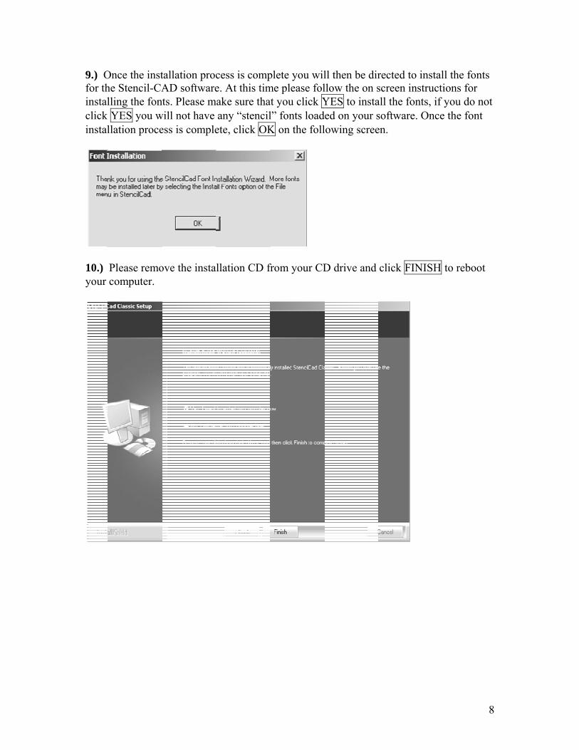
9.) Ofor thinstalclick instal
10.) your
Once the insthe Stencil-CAlling the fontYES you w
llation proce
Please remocomputer.
tallation procAD softwarets. Please ma
will not have ess is comple
ove the instal
cess is compe. At this timake sure thatany “stencil
ete, click OK
llation CD fr
plete you wilme please folt you click Yl” fonts loadeK on the foll
from your CD
ll then be dirllow the on sYES to instaed on your sowing scree
D drive and
rected to instscreen instruall the fonts, software. Onen.
click FINISH
tall the fontsuctions for if you do no
nce the font
H to reboot
8
s
ot
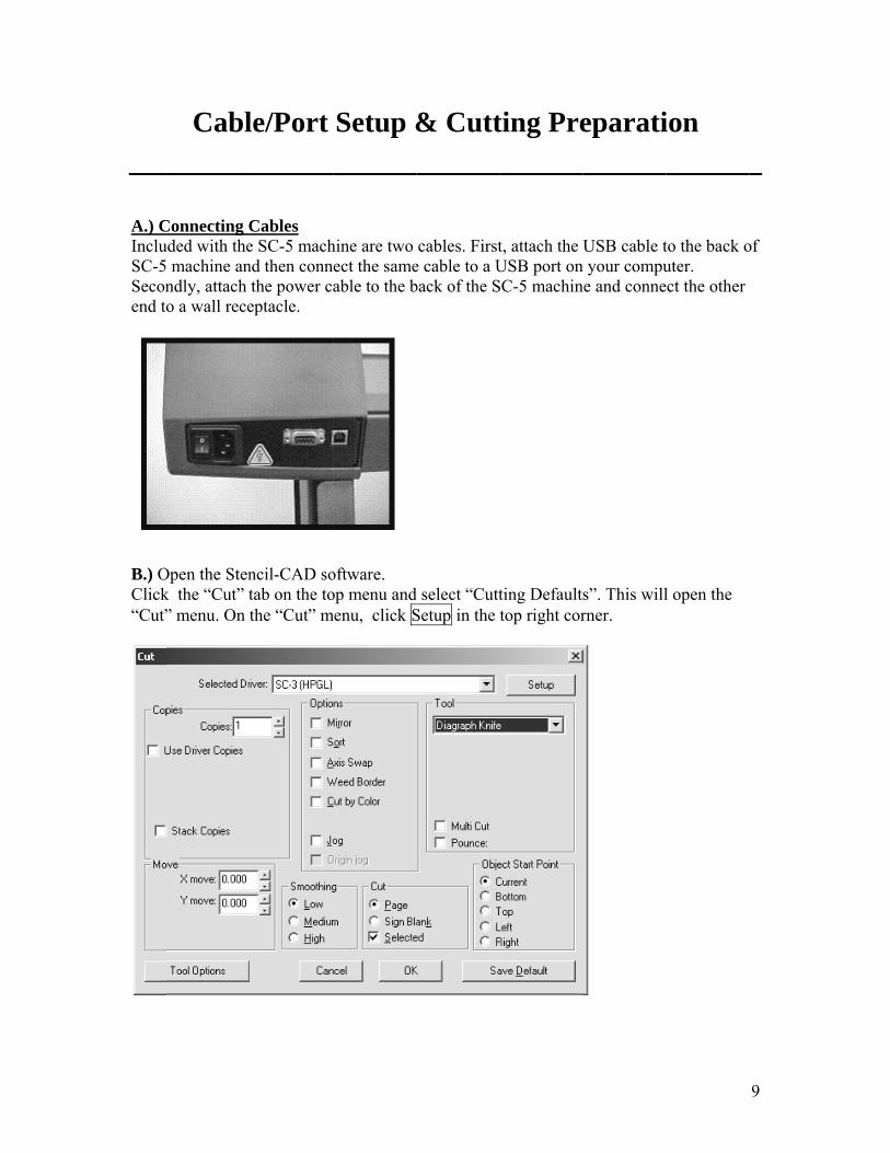
A.) CIncluSC-5Seconend to
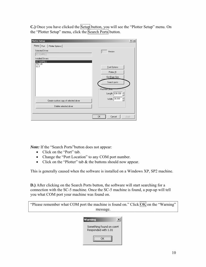
B.) OClick“Cut”
Cabl
Connecting Cuded with the machine anndly, attach o a wall rece
Open the Stenk the “Cut” t” menu. On t
le/Port
Cables e SC-5 machnd then connthe power c
eptacle.
ncil-CAD sotab on the tothe “Cut” m
Setup &
hine are two ect the sameable to the b
oftware. op menu and
menu, click S
& Cutt
cables. Firste cable to a Uback of the S
d select “CuttSetup in the
ting Pre
t, attach the USB port onSC-5 machin
ting Defaulttop right cor
eparati
USB cable tn your compune and conne
s”. This willrner.
ion
to the back outer. ect the other
l open the
9
of
C.) Othe “P
Note:
• • •
This D.) Aconneyou w “Plea
Once you havPlotter Setup
: If the “SeaClick on tChange thClick on t
is generally
After clickingection with twhat COM p
ase remembe
ve clicked thp” menu, cli
arch Ports”buthe “Port” tahe “Port Locthe “Plotter”
caused when
g on the Seathe SC-5 maport your ma
er what COM
he Setup buttck the Searc
utton does noab. cation” to an” tab & the b
n the softwa
rch Ports buachine. Onceachine was fo
M port the mm
ton, you wilch Ports butt
ot appear:
ny COM portbuttons shoul
are is installe
utton, the sofe the SC-5 mound on.
machine is foumessage.
l see the “Plton.
t number. ld now appe
ed on a Wind
ftware will stmachine is fou
und on.” Cli
lotter Setup”
ar.
dows XP, SP
tart searchinund, a pop-u
ick OK on th
1
” menu. On
P2 machine.
ng for a up will tell
he “Warning
0
g”
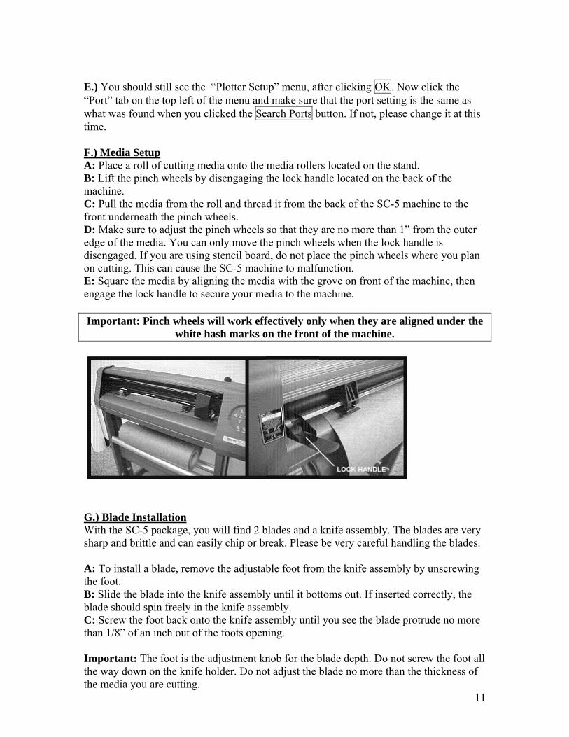
E.) Y“Portwhat time. F.) MA: PlB: LimachC: Pufront D: Medge disenon cuE: Sqengag Imp
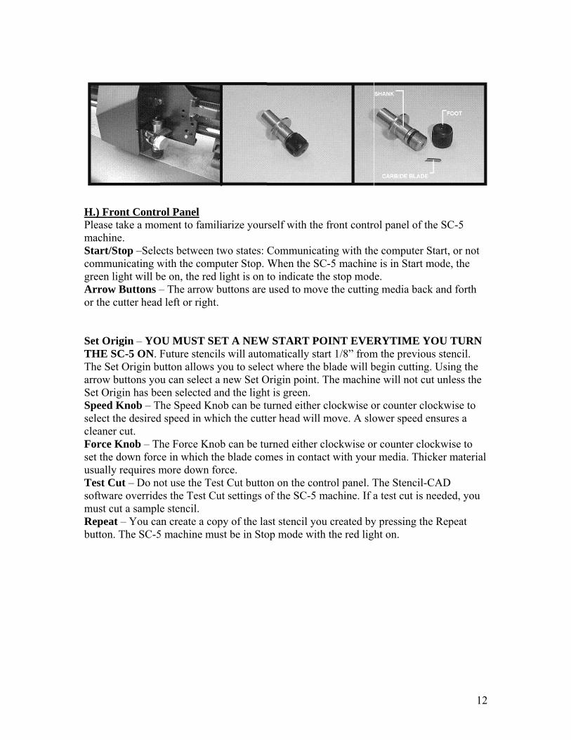
G.) BWith sharp A: Tothe foB: SlbladeC: Scthan Impothe wthe m
You should stt” tab on the was found w
Media Setuplace a roll ofift the pinch hine. ull the mediaunderneath
Make sure to of the media
ngaged. If youtting. This cquare the mege the lock h
ortant: Pinc
Blade Installthe SC-5 pa
p and brittle
o install a bloot. lide the bladee should spincrew the foo1/8” of an in
ortant: The way down onmedia you are
till see the “top left of th
when you cli
p f cutting medwheels by d
a from the rothe pinch whadjust the pia. You can o
ou are using can cause theedia by alignhandle to sec
ch wheels wwhite ha
lation ackage, you and can easi
lade, remove
e into the knn freely in thot back onto tnch out of th
foot is the adn the knife hoe cutting.
“Plotter Setuhe menu andicked the Se
dia onto the disengaging t
oll and threaheels. inch wheels only move thstencil boarde SC-5 mach
ning the medcure your me
will work effash marks o
will find 2 bily chip or br
e the adjustab
nife assemblyhe knife assemthe knife ass
he foots open
djustment knolder. Do no
up” menu, afd make sure earch Ports b
media rollerthe lock han
ad it from the
so that they he pinch whed, do not plahine to malfudia with the gedia to the m
fectively onlon the front
blades and a reak. Please
ble foot from
y until it botmbly. sembly untilning.
nob for the bot adjust the b
fter clicking that the port
button. If not
rs located onndle located o
e back of the
are no moreeels when thace the pinchunction. grove on fron
machine.
ly when theof the mach
knife assembe very care
m the knife a
ttoms out. If
l you see the
blade depth. blade no mo
OK. Now ct setting is tht, please chan
n the stand. on the back
e SC-5 mach
e than 1” fromhe lock handlh wheels whe
nt of the ma
y are alignehine.
mbly. The blaeful handling
assembly by
f inserted cor
blade protru
Do not screwore than the t
1
click the he same as nge it at this
of the
hine to the
m the outer le is ere you plan
achine, then
ed under the
ades are veryg the blades.
unscrewing
rrectly, the
ude no more
w the foot althickness of
1
s
n
e
y .
e
ll
H.) FPleasmachStartcommgreenArroor the Set OTHEThe SarrowSet OSpeeselectcleanForcset thusualTest softwmust Repebutto
Front Contrse take a momhine. t/Stop –Selemunicating wn light will bow Buttons –e cutter head
Origin – YOE SC-5 ON. FSet Origin buw buttons youOrigin has bed Knob – Tt the desired
ner cut. e Knob – Th
he down forclly requires mCut – Do no
ware overridecut a sample
eat – You can. The SC-5
rol Panel ment to fami
ects between with the combe on, the red– The arrow d left or right
OU MUST SFuture stencutton allowsu can select
een selected he Speed Kn
d speed in wh
he Force Knce in which tmore down fot use the Tees the Test Ce stencil.
an create a co5 machine m
iliarize your
two states: mputer Stop. d light is on tbuttons are
t.
ET A NEWcils will autos you to seleca new Set Oand the lightnob can be tuhich the cutt
nob can be tuthe blade comforce. est Cut buttoCut settings o
opy of the lamust be in Sto
rself with the
CommunicaWhen the SCto indicate thused to mov
W START POomatically stact where the
Origin point. t is green. urned either ter head will
urned either cmes in conta
on on the conof the SC-5 m
ast stencil yoop mode with
e front contr
ating with theC-5 machinehe stop modve the cutting
OINT EVERart 1/8” fromblade will bThe machin
clockwise omove. A slo
clockwise oract with your
ntrol panel. Tmachine. If a
ou created byh the red lig
ol panel of t
e computer Se is in Start m
de. g media bac
RYTIME Ym the previoubegin cuttingne will not cu
or counter clower speed e
r counter clor media. Thi
The Stencil-a test cut is n
y pressing thht on.
1
the SC-5
Start, or not mode, the
k and forth
YOU TURNus stencil. g. Using the ut unless the
ockwise to ensures a
ockwise to cker materia
CAD needed, you
he Repeat
2
N
e
al
13
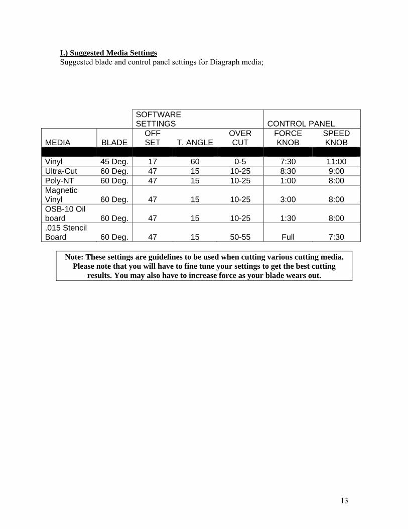
I.) Suggested Media Settings Suggested blade and control panel settings for Diagraph media;
SOFTWARE SETTINGS CONTROL PANEL
MEDIA BLADE OFF SET T. ANGLE
OVER CUT
FORCE KNOB
SPEED KNOB
Vinyl 45 Deg. 17 60 0-5 7:30 11:00 Ultra-Cut 60 Deg. 47 15 10-25 8:30 9:00 Poly-NT 60 Deg. 47 15 10-25 1:00 8:00 Magnetic Vinyl 60 Deg. 47 15 10-25 3:00 8:00 OSB-10 Oil board 60 Deg. 47 15 10-25 1:30 8:00 .015 Stencil Board 60 Deg. 47 15 50-55 Full 7:30
Note: These settings are guidelines to be used when cutting various cutting media.
Please note that you will have to fine tune your settings to get the best cutting results. You may also have to increase force as your blade wears out.
S
CMenu
M
T
Ton th
Fyou t
Tbetwe
S
Z
Z
Z
P
S
C
W
Po
D
Select Tools
Cut Tool Alu” Screen.
Measure To
Text Tools A
Text Compoe grid screen
Frame Textto type in a s
Text On Screen letters.
Spell Check
Zoom Tools
Zoom In
Zoom To Sig
Percentage Z
Shape Tools
Circle
Weed Borde
ower Weed
Decorative B
Sten
s Allows the
llows the use
ool Allows th
Allows the u
ose Allows tn.
t Compose set box size.
reen Kernin
k After the u
s Allows the
gn Blank
Zoom
s Allows the
Square
r Allows the
Border Sam
Border Allow
ncil-CA
user to selec
er to enter th
he user to m
user to custo
the user to ac
Same featur
ng Allows th
ser “selects
user to zoom
Zoom O
Zoom
user to crea
Polyg
e user to plac
me as Weed
ws the user t
AD Men
ct items on t
he “Cut Tool
measure any g
mize their fo
ccess the fon
res and the “
he user to ma
all” then spe
m in or out i
Out
m To Preview
ate the follow
on S
ce a weed bo
Border but w
to place bord
nu Icon
the grid scree
l Box” menu
given points
ont selection
nt settings an
Text Compo
anually set th
ell check the
in different w
Zo
w P
wing shapes.
Star
order around
with extra se
ders around
ns
en.
u and view th
on the grid
n
nd select the
ose” icon, bu
he spacing s
e file.
ways.
oom Selecte
an Object
Arrow
d the selected
ettings.
the selected
1
he “Cut
screen.
eir start point
ut also allow
ize in
ed Object
Fan
d file.
file.
4
t
ws
1.) SeThe g 2.) Oyour and th 3. MeStenc We ayou wand s 4.) TComprepre
et Origin Mgreen light sh
Open Stencildesktop. If yhen select th
edia Settingcil-CAD soft
are now readwill learn hosend your ste
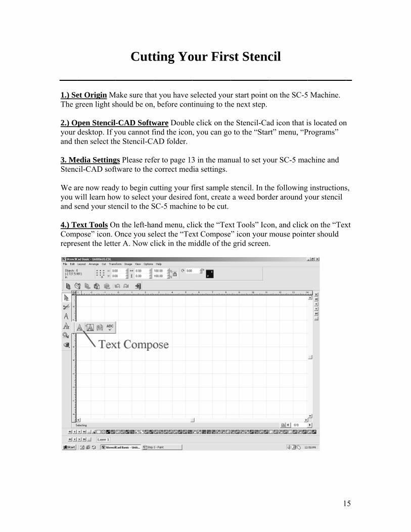
ext Tools Opose” icon. O
esent the lette
Cutt
Make sure thahould be on,
l-CAD Softwyou cannot fhe Stencil-CA
gs Please reftware to the
dy to begin cuw to select y
encil to the S
On the left-haOnce you seer A. Now c
ting Yo
at you have s, before cont
ware Doublefind the iconAD folder.
fer to page 13correct med
utting your fyour desired SC-5 machin
and menu, clelect the “Texlick in the m
our Firs
selected yourtinuing to th
e click on thn, you can go
3 in the mandia settings.
first sample font, create
ne to be cut.
lick the “Texxt Compose
middle of the
st Stenc
r start point he next step.
e Stencil-Cao to the “Star
nual to set yo
stencil. In tha weed bord
xt Tools” Ico” icon your
e grid screen
cil
on the SC-5
ad icon that irt” menu, “P
our SC-5 ma
he followingder around y
on, and clickmouse point.
1
5 Machine.
is located onPrograms”
achine and
g instructionsyour stencil
k on the “Texter should
5
n
s,
xt
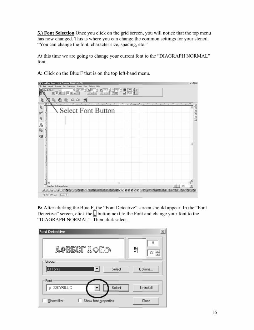
5.) Fohas n“You At thfont. A: Cl
B: AfDetec“DIA
ont Selectionow changedu can change
is time we a
lick on the B
fter clickingctive” screen
AGRAPH NO
on Once you d. This is whe the font, ch
are going to c
Blue F that is
g the Blue F, n, click the ↓ORMAL”. T
click on theere you can
haracter size,
change your
s on the top
the “Font D↓ button nexThen click se
e grid screenchange the c, spacing, etc
r current font
left-hand me
Detective” sct to the Font
elect.
n, you will nocommon settc.”
t to the “DIA
enu.
reen should t and change
otice that thetings for you
AGRAPH N
appear. In the your font to
1
e top menu ur stencil.
ORMAL”
he “Font o the
6

C: Nscree
D: Ohighlyou hYou c
6.) Wyour your board
ow type the en, except on
nce you havlight the texthave “Selectcan also sele
Weed Borderentire stencistencil from
d of any kind
Note:
word “Sampn the word “S
ve clicked ont on your gried” your steect your sten
rs The Weedil. A weed b
m the backingd, we do not
If you are u
ple” on yourSample”.
n the grid scrd screen. Wh
encil. In ordencil by going
d Border is aorder is prim
g of the materecommend
using stenci
r grid screen
reen, you wihen you seeer to cut out g to “Edit” th
a border thatmarily used oerial. Please d that you us
il board, ple
n, then click a
ll notice 9 smthe 9 small a stencil, it mhen “Select A
t is placed aron two ply mnote that if y
se a weed bo
ease skip ste
anywhere on
mall squaressquares, thismust first beAll” on the t
round the oumaterial so yoyou are usinrder with yo
eps A, B & C
1
n the grid
s that s means that e selected. top menu.
uter edge of ou can peel
ng stencil our stencils.
C.
7
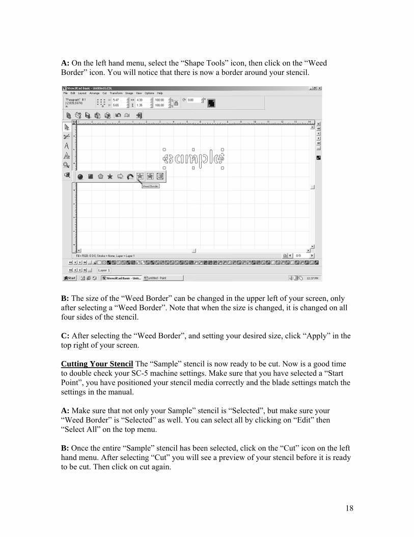
A: OBord
B: Thafter four s C: Atop ri Cuttito doPointsettin A: M“Wee“Sele B: Onhand to be
n the left haner” icon. Yo
he size of theselecting a “sides of the s
fter selectingight of your
ing Your Stuble check yt”, you have ngs in the ma
Make sure thaed Border” iect All” on th
nce the entirmenu. Aftercut. Then cl
nd menu, seou will notice
e “Weed Bo“Weed Bordstencil.
g the “Weedscreen.
tencil The “Syour SC-5 mpositioned y
anual.
at not only ys “Selected”he top menu
re “Sample” r selecting “lick on cut a
lect the “Shae that there i
order” can beder”. Note th
d Border”, an
Sample” stenmachine settinyour stencil m
our Sample”” as well. You.
stencil has bCut” you wi
again.
ape Tools” iis now a bor
e changed inat when the
nd setting yo
ncil is now rngs. Make sumedia correc
” stencil is “ou can select
been selectedill see a prev
icon, then clider around y
n the upper lesize is chang
our desired s
ready to be cure that youctly and the
Selected”, bt all by clicki
d, click on thview of your
ick on the “Wyour stencil.
eft of your scged, it is cha
size, click “A
cut. Now is au have selecte
blade setting
ut make sureing on “Edit
he “Cut” icostencil befo
1
Weed
creen, only anged on all
Apply” in the
a good time ed a “Start gs match the
e your t” then
on on the leftore it is ready
8
e
e
ft y

19
Checking Your Stencil After your “Sample” stencil has finished cutting, this would be a good time to tweak your settings. You want to look at your “Sample” stencil and decide if there are any setting changes that need to be made. Ask yourself the following questions to see if any changes need to be made. Q: Did my stencil cut all the way through my stencil board. A: If your stencil did NOT cut all the way through your stencil board, the blade needs to be adjusted. Turn the blade out of the foot holder no more than a ¼ of a turn, then re-cut your stencil. If you are still having problems cutting out the stencil completely, keep adjusting the blade until the stencil cuts out completely. Q: Did my stencil cut completely through the two ply material? “Examples of two ply materials are Ultra-Cut, Poly-NT and Vinyl.” A: When cutting two ply material, you do NOT want to cut all the way through the entire sheet. You only want to cut the top layer and scar the bottom, the bottom layer is just the backing for the material. If you are cutting all the way through the material, the blade needs to be adjusted. Turn the blade in to the foot holder no more than ¼ of a turn, then re-cut your stencil. If you are still cutting the entire piece of material, keep adjusting your blade until you only scar the backing of the material. Q: The blade cut all the way through the stencil board, but it seems to be cutting to deep? A: Yes, it is possible to cut the stencil board to deep. You can tell that you have cut the stencil board to deep, by looking at the cutting strip on your SC-5 machine. The cutting strip is a small thin strip of plastic that the blade comes into contact with while cutting your stencil. If you notice big gouges or deep cuts in the cutting strip, you have cut your stencil to deep. Turn the blade into the foot holder ¼ of a turn, and re-cut your stencil. Note: This User’s Guide is intended only as a starting point & general guideline for
setting up & operating your SC-5 stencil machine & Stencil-CAD software. Each machine will not use exactly the same settings every time a stencil is cut. There are just too many variables involved in the machine & software operation for that to be
true. Depending on the number of stencils the end-user cuts in a given day, it is possible that they would have to tweak the machine daily to get clean, consistent
cuts. Hands-on operation and playing with the settings is often times the best way to learn how to best use the SC-5 & Stencil-CAD system.
20
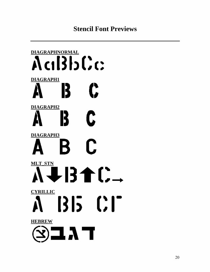
Stencil Font Previews
DIAGRAPHNORMAL
DIAGRAPH1
DIAGRAPH2
DIAGRAPH3
MLT_STN
CYRILLIC
HEBREW
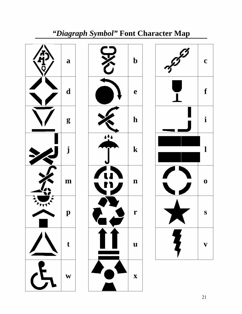
“Diag
a
d
g
j
m
p
t
w
agraph S
a
d
g
j
m
p
t
w
Symboll” Font
b
e
h
k
n
r
u
x
Chara
b
e
h
k
n
r
u
x
acter M
2
Map
v
21
c
f
i
l
o
s
v

22
Frequently Asked Questions
Q: I connected my USB Dongle before installing Stencil-Cad, and now Stencil-Cad cannot recognize the Dongle. A: Follow these instructions 1. From the Windows Start Menu, open the Control Panel 2. From the Control Panel under Windows ME & 98SE, double-click the Devices icon to display all of the hardware that has been connected to this workstation. Proceed to step 5. 3. From the Control Panel under Windows 2000 & XP, double-click the System icon. 4. From the Hardware tab, click the Device Manager button to display all of the hardware that has been connected to this workstation. 5. Within the Device Manager window, locate the USB device that is indentified as an unknown device, and then choose uninstall and delete the unknown USB device. 6. Close the Device Manager “and if necessary click OK to close the System Properties dialog”. 7. Disconnect the USB Dongle. 8. Place the Stencil-Cad program CD into the workstation CD-ROM drive. If prompted to choose a language, click cancel. 9. From the Start Menu, choose the Run item. 10. Form the Run dialog, click Browse and locate the file called “HINSTALL.EXE” which is on the Stencil-Cad CD. 11. After the “HINSTALL.EXE” file has been found, click within the edit file and type “-1” (space-minus-eye) after the file name. 12. Click OK to close the Run dialog and the USB dongle driver software will be reinstalled. 13. After the USB driver software has been reinstalled, reboot your computer Q: When I try to send a file to the SC-5 machine to be cut, I receive the following error message “Cannot Locate Security Device”? A: There are several solutions to this problem, please check all of the following. 1. Make sure the dongle is secured in the USB port. 2. Plug the dongle into another USB port, to make sure you do not have a USB problem with your computer. 3. Your password might be incorrect in your software. Check the Stencil-CAD settings in the top menu. 4. Drivers on your computer might need updated. “Windows XP SP2 only” Contact support to download or have new drivers e-mailed to you.

23
Q: When I send a file to the SC-5 machine to be cut, the screen shows bytes sent to the machine, but the SC-5 machine is not cutting? A: Make sure that you have set a start point on the SC-5 machine, the green light should be on. If that does not help, your “COM Port” settings could be wrong in your software. Please refer to page 10 to change the COM Port settings. Q: There seems to be an over cut on my stencils, or small swirl marks at the connecting points? A: The “Speed” knob on the SC-5 machine might be set too high. Lower the “Speed” setting and re-cut your stencil. Also make sure that you have a sharp blade installed, a dull or chipped blade can cause cutting problems. If you are still having problems, select “Cut” then “Tool Options” on the top menu, and make sure that the “Blade Off-Set” is set to .047. Q: How do I cut multiple copies of a stencil? A: When you are ready to cut your stencil, select “Cut” on the top menu, and change the “Repeat” number. Q: When the SC-5 machine is cutting a stencil, it stops in the middle of cutting the stencil? A: See LED Codes Chart Q: Can I install Stencil-CAD on multiple computers? A: No, Stencil-CAD is made for stand-alone computers only and cannot be networked. Q: I do not have any of the “Stencil” fonts installed into my software? A: The “Stencil” fonts are installed with the software during the installation. To install the fonts, click “File” on the top menu, then “Install”, then select “Font”. Make sure that CADLINK.VEF is checked. Click the “Search Now” button and then “Install All”.
24
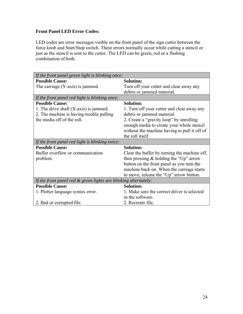
Front Panel LED Error Codes: LED codes are error messages visible on the front panel of the sign cutter between the force knob and Start/Stop switch. These errors normally occur while cutting a stencil or just as the stencil is sent to the cutter. The LED can be green, red or a flashing combination of both. If the front panel green light is blinking once: Possible Cause: Solution: The carriage (Y-axis) is jammed. Turn off your cutter and clear away any
debris or jammed material. If the front panel red light is blinking once: Possible Cause: Solution: 1. The drive shaft (X-axis) is jammed. 2. The machine is having trouble pulling the media off of the roll.
1. Turn off your cutter and clear away any debris or jammed material. 2. Create a “gravity loop” by unrolling enough media to create your whole stencil without the machine having to pull it off of the roll itself.
If the front panel red light is blinking twice: Possible Cause: Solution: Buffer overflow or communication problem.
Clear the buffer by turning the machine off, then pressing & holding the “Up” arrow button on the front panel as you turn the machine back on. When the carriage starts to move, release the “Up” arrow button.
If the front panel red & green lights are blinking alternately: Possible Cause: Solution: 1. Plotter language syntax error. 1. Make sure the correct driver is selected
in the software. 2. Bad or corrupted file. 2. Recreate file.

25
Warranty Information
Seller and Manufacturers only obligations shall be: To repair or replace at no charge any part of the machine proved to be defective within one year of the purchase date. When such a defect occurs labor will be covered for 180 days after the purchase date. That the SC-5 Stencil Machine has been used in accordance with the user’s guide and that it has not been tampered with, abused, used for purposes other than those described in this guide, or used to cut materials that are not purchased from Diagraph MSP or a Diagraph Distributor. This warranty only covers the SC-5 Stencil Machine and Stencil-CAD software and not the user’s computer systems or input devices connected to the computer.

26
Notes
________________________________________________________________________________________________________________________________________________________________________________________________________________________________________________________________________________________________________________________________________________________________________________________________________________________________________________________________________________________________________________________________________________________________________________________________________________________________________________________________________________________________________________________________________________________________________________________________________________________ ________________________________________________________________________________________________________________________________________________________________________________________________________________________________________________________________________________________________________________________________________________________________________________________________________________________________________________________________________________________________________________________________________________________________________________________________________________________________________________________________________________________________________________________________________________________________________________________________________________________ ________________________________________________________________________________________________________________________________________________________________________________________________________________________________________________________________________________________________________________________________________________________________________________________________________________________________________________________________________________________________________________________________________________________________________________________________________________________________________________________________________________________________________________________________________________________________________________________________________________________ ________________________________________________________________________________________________________________________________________________________________________________________________________________________________________________________________________________________________________________________________________________________________________________________________________________________________________________________________________________________________________________________________________________________________________________________________